

Page 1
E-M-HW4v3-F2-020_10
Rotronic AG
Bassersdorf, Switzerland
Document code
Unit
HW4 software version 3: Device Manager
HC2-AW-USB Water Activity Probe
Instruction Manual
Document Type
Page
1 of 12
Document title
HW4 Software version 3
Device Manager
HC2-AW-USB Water Activity Probe
© 2011; Rotronic AG E-M-HW4v3-F2-020_10
Page 2

E-M-HW4v3-F2-020_10
Rotronic AG
Bassersdorf, Switzerland
Document code
Unit
HW4 software version 3: Device Manager
HC2-AW-USB Water Activity Probe
Instruction Manual
Document Type
Page
2 of 12
Document title
Table of contents
1 ORGANIZATION OF THE HW4 MANUALS ....................................................................................... 3
2 OVERVIEW ......................................................................................................................................... 4
3 DEVICE MANAGER ............................................................................................................................ 4
3.1 Device Manager Menu Bar ................................................................................................................ 5
3.2 Device Information ............................................................................................................................. 8
3.3 Settings .............................................................................................................................................. 9
3.4 Alarm ................................................................................................................................................10
3.5 RH Sensor Status .............................................................................................................................11
4 DOCUMENT RELEASES.................................................................................................................. 12
© 2011; Rotronic AG E-M-HW4v3-F2-020_10
Page 3

E-M-HW4v3-F2-020_10
Rotronic AG
Bassersdorf, Switzerland
Document code
Unit
HW4 software version 3: Device Manager
HC2-AW-USB Water Activity Probe
Instruction Manual
Document Type
Page
3 of 12
Document title
HW4 Manuals
Contents
HW4 Main Book
General software description
Installation, start-up and settings
Device connection methods
Functions common to all devices used with HW4
Device Specific Functions 1
(separate book for each device type or model)
Legacy devices (original HygroClip technology):
o HygroLog NT data logger
o HygroFlex 2, HygroFlex 3 and M3 transmitters
o HygroLab 2 and HygroLab 3 bench indicators
o HygroPalm 2 and HygroPalm 3 portable indicators
o HygroClip DI digital interface
o HygroClip Alarm programmable logic
o HygroStat MB
Device Manager (device configuration) and other device
specific functions
Probe Adjustment 1
Humidity and temperature adjustment function common to
all legacy devices (original HygroClip technology)
Device Specific Functions 2
(separate book for each device type or model)
Devices based on the AirChip 3000 technology:
o HygroClip 2 (HC2) probes
o HF3 transmitters and thermo-hygrostats
o HF4 transmitters
o HF5 transmitters
o HF6 transmitters
o HF7 transmitters
o HL20 and HL21 data loggers
o HP21, HP22 and HP23 hand-held indicators
o HygroLab C1 table-top indicator
o LOG-RC Wireless Data Loggers
o Custom designed OEM products
Device Manager (device configuration) and AirChip 3000
functions
Probe Adjustment 2
Humidity and temperature adjustment function common to
all devices based on the AirChip 3000 technology
Data Recording Function
Data recording function common to all devices based on the
AirChip 3000 technology
1 ORGANIZATION OF THE HW4 MANUALS
The HW4 manuals are organized in separate books so as to limit the size of the individual documents. A list
of the HW4 manuals is provided in document E-M-HW4v3-DIR
Both the HW4 manuals (software) and device specific manuals (hardware) are available on the HW4 CD.
The manuals can also be downloaded from several of the ROTRONIC web sites.
© 2011; Rotronic AG E-M-HW4v3-F2-020_10
Page 4
E-M-HW4v3-F2-020_10
Rotronic AG
Bassersdorf, Switzerland
Document code
Unit
HW4 software version 3: Device Manager
HC2-AW-USB Water Activity Probe
Instruction Manual
Document Type
Page
4 of 12
Document title
HW4 Functional Modules
for the HC2-AW-USB
Usage
Device Manager
o HC2-AW-USB probe: user configurable settings
o AirChip 3000 user functions: enable and configure
2 OVERVIEW
This section of the HW4 manual covers only the following HW4 module:
o The Data Logging module is common to all probes and instruments based on the AirChip 3000
technology and is separately described in the HW4 manual E-M-HW4v3-DR-001
o The Probe Adjustment module is used calibrate and adjust the probe humidity and temperature signals.
This module is common to all probes and instruments based on the AirChip 3000 technology and is
separately described in the HW4 manual E-M-HW4v3-A2-001
o HW4 functions that are not device dependent are covered in the HW4 manual E-M-HW4v3-Main.
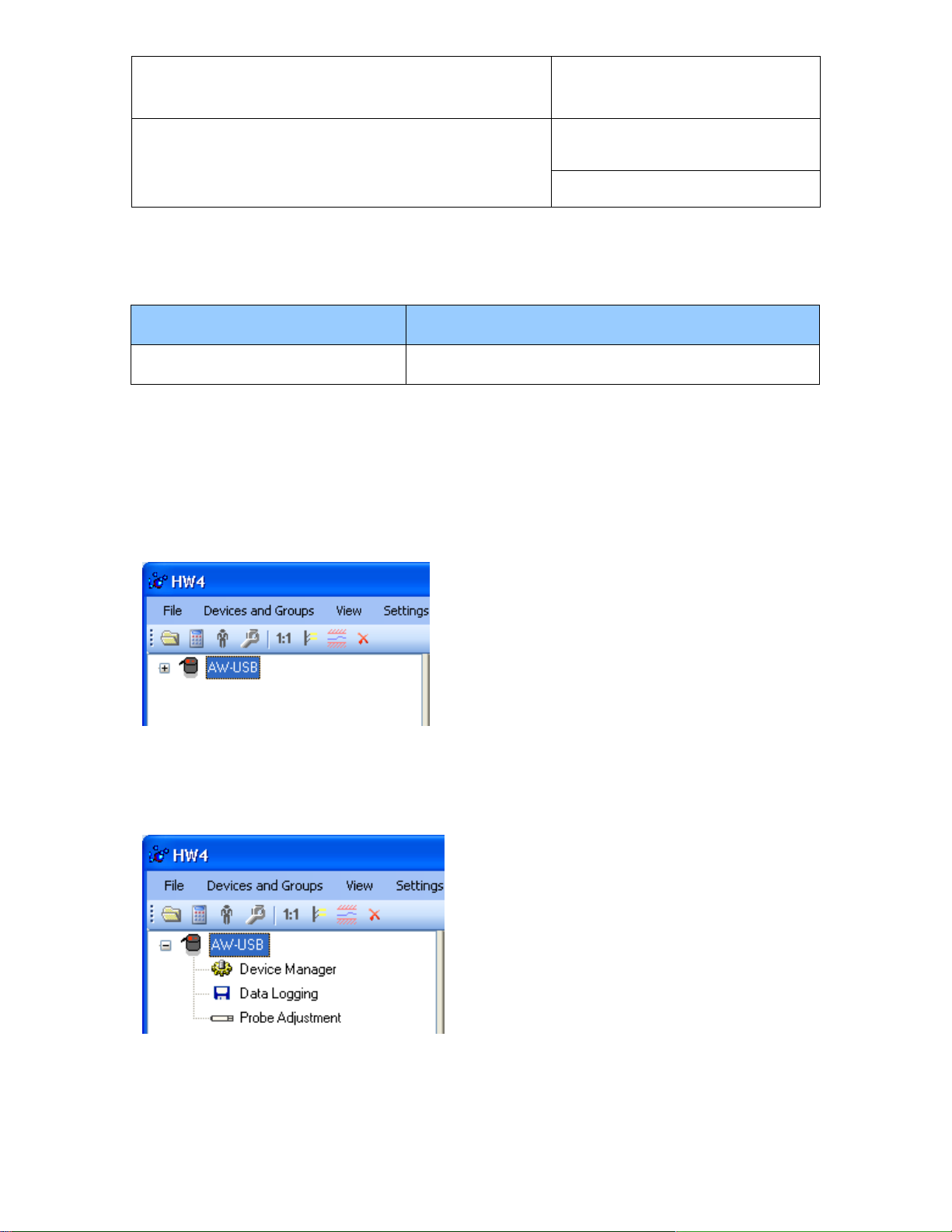
When HW4 has detected a HC2-AW-USB probe, the probe
appears as an icon in the left pane of the HW4 main
screen. Click on the + sign to the left of the probe icon to
display a list of the available functional modules.
3 DEVICE MANAGER
Device Manager is used to configure the HC2-AW-USB probe and to enable, configure and access the
AirChip 3000 functions.
© 2011; Rotronic AG E-M-HW4v3-F2-020_10
To select the Device Manager module, click on it with
the left mouse button. HW4 opens the Device Manager
form.
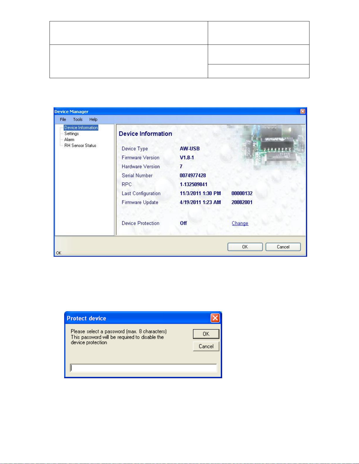
Device Manager automatically interrogates the probe
and downloads its current configuration.
Page 5

E-M-HW4v3-F2-020_10
Rotronic AG
Bassersdorf, Switzerland
Document code
Unit
HW4 software version 3: Device Manager
HC2-AW-USB Water Activity Probe
Instruction Manual
Document Type
Page
5 of 12
Document title
The different sub-forms that are available within Device Manager are listed in a tree located on the left pane
of the Device Manager form. To select a sub-form, click on it with the left mouse button.
3.1 Device Manager Menu Bar
The Device Manager menu bar is located at the top of the form.
File
The file menu is used to save to the PC, or to retrieve from the PC, the configuration settings of the HC2AW-USB probe. The settings are saved in an XML file with the extension DAT. Saving the configuration
settings to a file is useful for several reasons:
- provides a backup when the probe configuration has been changed in error
- provides a means of quickly configuring a replacement probe in the exact same manner as the
original probe when the original probe is defective
- provides a means of quickly configuring a number of identical probes
● Open: opens the device configuration folder specified in HW4 Global Settings - File Locations Tab -
and displays all available probe and device configuration files (extension DAT). Select the appropriate
file and click on Open in the explorer form. The contents of the configuration file are loaded to the
Device Manager form. Review the contents of the Device Manager sub-forms. Click on the Device
Manager OK button to write the configuration settings to the probe or click on the Cancel button to leave
the probe unchanged.
© 2011; Rotronic AG E-M-HW4v3-F2-020_10
Page 6

E-M-HW4v3-F2-020_10
Rotronic AG
Bassersdorf, Switzerland
Document code
Unit
HW4 software version 3: Device Manager
HC2-AW-USB Water Activity Probe
Instruction Manual
Document Type
Page
6 of 12
Document title
● Save As: saves the current configuration to an XML file with the extension DAT) in the device
configuration folder specified in HW4 Global Settings - File Locations Tab. If so desired, any directory
and any file type may be specified.
● Close: exits Device Manager
© 2011; Rotronic AG E-M-HW4v3-F2-020_10
Page 7

E-M-HW4v3-F2-020_10
Rotronic AG
Bassersdorf, Switzerland
Document code
Unit
HW4 software version 3: Device Manager
HC2-AW-USB Water Activity Probe
Instruction Manual
Document Type
Page
7 of 12
Document title
Tools
● Firmware Update: This tool is used to update the firmware of the HC2-AW-USB probe after downloading
a new firmware file from the ROTRONIC website to your PC. Firmware files are given a name that shows
both to which device the file applies and the version number of the firmware. All firmware files have the
extension HEX. The ROTRONIC website will publish firmware updates as required.
The tool opens a form that allows you to specify the folder where the firmware update file is located and to
select the file. Click on OPEN to start the update process.
IMPORTANT: the probe must be powered during the entire process. Loss of power when the probe is being
updated may have unexpected results and prevent future operation of the probe.
● Generate Protocol: generates a Device Configuration Protocol. This text file is automatically saved in the
folder specified in HW4 Global Settings - File Locations Tab. If so desired, any directory and any file type
may be specified. This action is not recorded in the User Event file.
Help:
● HW4 Help: Opens HW4 Help
● About HW4: Displays the version number and ID number of HW4
© 2011; Rotronic AG E-M-HW4v3-F2-020_10
Page 8
E-M-HW4v3-F2-020_10
Rotronic AG
Bassersdorf, Switzerland
Document code
Unit
HW4 software version 3: Device Manager
HC2-AW-USB Water Activity Probe
Instruction Manual
Document Type
Page
8 of 12
Document title
3.2 Device Information
● Device Protection: This function is used to prevent unauthorized access to critical functions such as
probe configuration changes, probe adjustment, etc. For a description, see document E-IN-HW4v2.1Main
To protect the probe, click on the underlined link next to Device Protection. HW4 opens the following
form where a password can be entered (maximum 8 characters):
Click on the Device Manager OK button to write the new protection settings to the probe.
FORGOT THE PASSWORD? - Power down the probe. After powering up the probe, you have about
one minute to use the default password !resume! (include the exclamation marks). After one minute the
default password is no longer accepted.
© 2011; Rotronic AG E-M-HW4v3-F2-020_10
Page 9

E-M-HW4v3-F2-020_10
Rotronic AG
Bassersdorf, Switzerland
Document code
Unit
HW4 software version 3: Device Manager
HC2-AW-USB Water Activity Probe
Instruction Manual
Document Type
Page
9 of 12
Document title
3.3 Settings
Device Name: As far as possible use a unique device name (maximum 12 characters)
Humidity: enter here the letters to be used for Water Activity
Temperature: Left click on the arrow to the right of the text box and select the temperature
engineering unit (˚C or ˚F).
Calculation: Left click on the arrow to the right of the text box and select from the following: No
calculation, Dew Point or Frost Point
Limit humidity to 1.000 Aw: typically, the humidity sensor gives a reading slightly above 1.000 Aw
when condensation occurs at the surface of the sensor. Check this box to limit the maximum value of
humidity to 1.000 Aw
Generate Humidity Fixed Value / Generate Temperature Fixed Value: place a check mark in these
boxes to make the HC2-AW-USB probe generate fixed humidity and temperature values instead of
the actual measurements.
The fixed values must be with the following limits: -999.99 and 9999.99
© 2011; Rotronic AG E-M-HW4v3-F2-020_10
Page 10

E-M-HW4v3-F2-020_10
Rotronic AG
Bassersdorf, Switzerland
Document code
Unit
HW4 software version 3: Device Manager
HC2-AW-USB Water Activity Probe
Instruction Manual
Document Type
Page
10 of 12
Document title
Use of the HC2-AW-USB probe as a simulator serves the purpose of verifying the digital signal transmission
after completing an installation. Whenever the humidity and/or temperature signal is set to a fixed value, this
is reported on the HW4 main screen (current Values tab) as shown below. The fixed value is shown in red
when the probe is not selected.
3.4 Alarm
Alarm conditions can be defined for water activity, temperature and the calculated parameter. Values that
are below the low alarm value or above the high alarm value will trigger an alarm. The value specified for the
alarm function hysteresis is used for both the low and the high alarm.
All versions of HW4 will show an out-of-limits value alarm in red on the monitor screen. In addition, HW4
Professional can be configured (HW4 global settings - Alarm settings tab) to display an alarm table and
generate a report whenever an out-of-limits condition occurs.
© 2011; Rotronic AG E-M-HW4v3-F2-020_10
Page 11

E-M-HW4v3-F2-020_10
Rotronic AG
Bassersdorf, Switzerland
Document code
Unit
HW4 software version 3: Device Manager
HC2-AW-USB Water Activity Probe
Instruction Manual
Document Type
Page
11 of 12
Document title
Sensor Test Interval
Enter the desired time interval for the automatic sensor test
(minutes). Recommended value: 60
Test sensor only above
The RH sensor will be tested only when the measured humidity
value is equal to or higher than the value entered in this text box.
Default value: 60 (may be changed by factory)
Note: a different test is used to detect major sensor problems
such as an open circuit or a short circuit. This test is not affected
by the settings entered in this form.
Not available
The sensor has not been tested. Verify the RH sensor test settings (Device
Manager menu bar > Tools). The sensor will not be tested as long as the current
value of %RH is below the value entered in the box labeled “Test above [%RH}”
3.5 RH Sensor Status
For a description of the RH sensor test function see document E-T-AC3000-DF-V1
The sensor test function uses the settings entered in the form shown below.
After each test, the sensor status is reported as Good, SQ-Tuned or Bad.
Automatic Sensor Test: place a check mark in this box to enable the automatic RH sensor test.
Depending on the test result, the RH sensor status is reported as follows:
© 2011; Rotronic AG E-M-HW4v3-F2-020_10
Page 12

E-M-HW4v3-F2-020_10
Rotronic AG
Bassersdorf, Switzerland
Document code
Unit
HW4 software version 3: Device Manager
HC2-AW-USB Water Activity Probe
Instruction Manual
Document Type
Page
12 of 12
Document title
Good
The sensor error is less than the correction threshold value. The correction offset
(SQ) for sensor drift correction is automatically set to zero
SQ-Tuned
The sensor error is equal or larger than the correction threshold value but less
than the defective threshold. A correction (SQ) is automatically added to the value
measured by the sensor. The correction (SQ) is calculated based on the %RH
currently measured by the sensor and on the coefficients A, B and C (RH sensor
test settings).
Bad
The sensor error is equal or larger than the defective threshold value
Release
Software Ver.
Date
Notes
_10
3.1.0
Nov. 9, 2011
Original release
The probe issues a digital alarm only when both of the following conditions are met: (a) the %RH
measured prior to the test is at least equal to the value entered in Tools > RH Sensor Test Settings >
Test above [%RH] box and (b) the humidity sensor test returns the result “Bad”. The text “Bad Sensor
Alarm” appears in red on the HW4 main screen. HW4 Professional can be configured (HW4 global
settings - Alarm settings tab) to display an alarm table and generate a report whenever a device alarm
condition occurs.
Check Humidity Sensor Now: this link works only when the probe is configured with the automatic
RH sensor test function enabled and when the measured value of humidity is above the limit
entered in the RH Sensor Test Settings form. When both conditions are met, click on this link to
manually run a humidity sensor test and eventually have the probe apply a correction to the
humidity output signal
4 DOCUMENT RELEASES
© 2011; Rotronic AG E-M-HW4v3-F2-020_10
 Loading...