

Page 1
E-M-HC2-accessories_24
Document code Unit
Rotronic AG
Bassersdorf, Switzerland
Accessories and Parts
for probes, indicators and transmitters
Document title
Accessories and Parts
for probes, indicators and transmitters
Instruction Manual
Document Type
Page
1 of 23
© 2009-2010; Rotronic AG E-M-HC2-accessories_23
Page 2

E-M-HC2-accessories_24
Document code Unit
Rotronic AG
Bassersdorf, Switzerland
Accessories and Parts
for probes, indicators and transmitters
Document title
Instruction Manual
Page
2 of 23
Document Type
Table of contents
1
Configuration and communication software .................................................................................... 3
Service cables for transmitters and indicators ................................................................................. 3
2
Supply voltage adapters for the HC2 probes .................................................................................... 4
3
Extension cables for the HC2 probes ................................................................................................ 5
4
Standard passive cables .................................................................................................................. 5
4.1
Passive cables and connectors for OEM applications ...................................................................... 6
4.2
Cables with digital signal booster ..................................................................................................... 7
4.3
5 Digital interface adapters for the HC2 probes .................................................................................. 8
USB adapter ..................................................................................................................................... 8
5.1
RS-232 adapter ................................................................................................................................ 8
5.2
Ethernet adapter ............................................................................................................................... 8
5.3
RS-485 and Modbus adapters .......................................................................................................... 9
5.4
6
Digital interface adapter for the HC2-S3C0 probe .......................................................................... 11
USB adapter ................................................................................................................................... 11
6.1
7 RS-485 converters and junction boxes ........................................................................................... 12
7.1
USB / RS-485 converter ................................................................................................................. 12
Ethernet / RS-485 converter ........................................................................................................... 14
7.2
7.3
Junction box for RS-485 netw or ks .................................................................................................. 17
8 Mounting hardware ........................................................................................................................... 19
8.1
Mounting hardware for through-wall probe installation ................................................................... 19
Mounting hardware for transmitter enclosure ................................................................................. 20
8.2
9
Calibration accessories .................................................................................................................... 20
Dust filters ......................................................................................................................................... 21
10
10.1
Spare filters .................................................................................................................................... 21
Dust filter part s ............................................................................................................................... 22
10.2
11
Maximum temperature limit for connectors, cables and adapters ............................................... 23
Document releases ........................................................................................................................... 23
12
© 2009-2010; Rotronic AG E-M-HC2-accessories_23
Page 3
E-M-HC2-accessories_24
Document code Unit
Rotronic AG
Bassersdorf, Switzerland
Accessories and Parts
for probes, indicators and transmitters
Document title
Instruction Manual
Page
3 of 23
Document Type
1 Configuration and comm unication software
The ROTRONIC HW4 software (version 2.1.0 or higher) allows configuring the AirChip 3000 probes and
instruments.
HW4 is compatible with Windows XP, Vista and NT4 with SP6a or higher. For more details see separate
instruction manual provided with the software.
Order Code Description
HW4-E
HW4-P
HW4 software, Standard Edition ( single user)
HW4 Professional Edition, ERES regulations compliant (FDA / GAMP), multi user
2 Service cables for transmitters and indicator s
Order Code Description
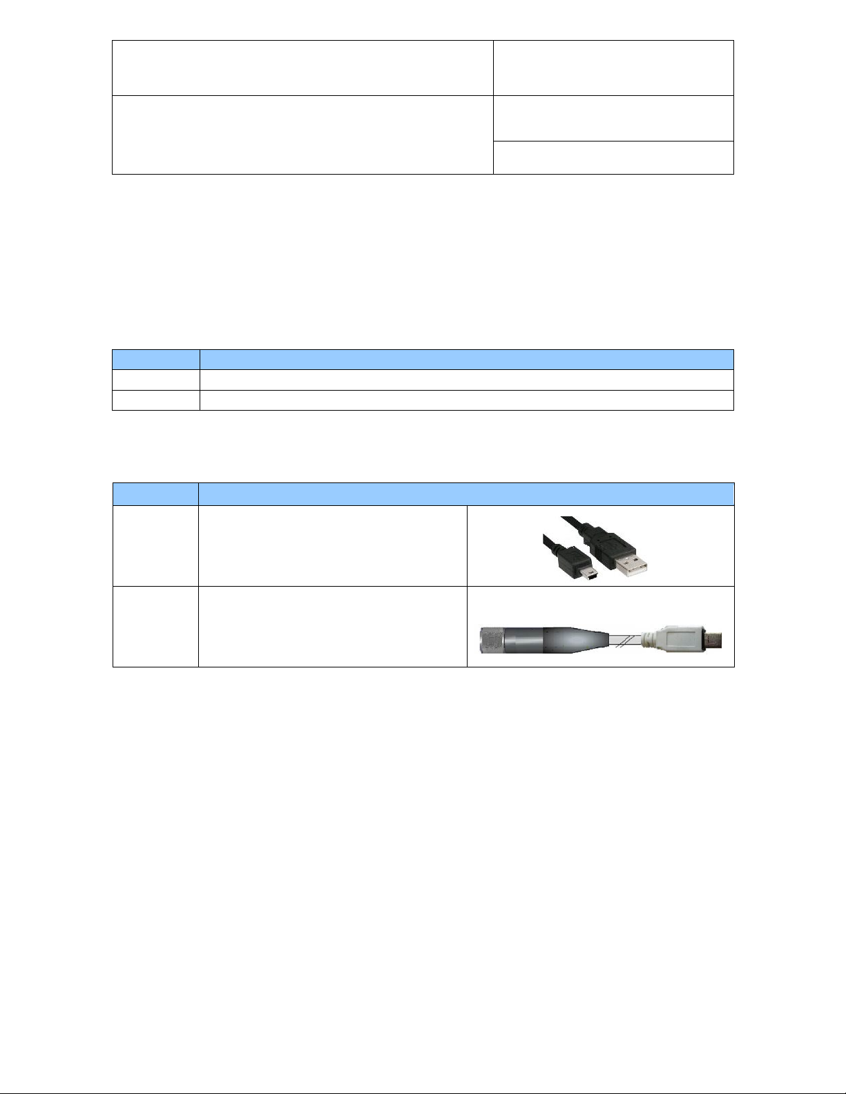
AC3006
Mini-USB service connector (UART) to a PC
USB port. Cable electronics convert UART
interface to USB interface. Approximate
length: 1.7 m
Mini-USB service connector (UART) to 7-pin
AC2001
Notes:
o The active electronic circuit of cable AC3006 is powered directly from the USB port (PC or hub). Both
o Prior to using cable AC3006 the ROTRONIC USB driver must be installed on the PC (available from
probe connector of the HP23 hand-held
calibrator or other instrument w ith display and
keypad. Approximate length: 1.7 m
the AC3006 and AC2001 do not provide power to the transmitter or indicator and these must be
powered separately.
the HW4 CD or from www.rotronic-humidity.com). For installation instructions see document
E-M-HW4v3-Main (§ 7.3).
© 2009-2010; Rotronic AG E-M-HC2-accessories_23
Page 4
E-M-HC2-accessories_24
Female connector (black) with built-in voltage
1 m (3.2 ft) cable with tinned ends
Female connector (white) with built-in voltage
1 m (3.2 ft) cable with tinned ends
Specifications
Supply voltage to adapter
5…24 VDC / 5…16 VAC
Supply voltage to probe
3.3 VDC
Current consumption (includes HC2 probe)
< 4 mA
Wire color
Name
Function
Humidity: 0…1 V = 0…100%RH (default)
Document code Unit
Rotronic AG
Bassersdorf, Switzerland
Accessories and Parts
for probes, indicators and transmitters
Document title
3 Supply voltage adapters for the HC2 probes
Order Code Description
E2-01XX-ACT
E2-02XX-ACT S ame as E2-01XX-ACT with 2m (6.5 ft) cable
E2-05XX-ACT S ame as E2-01XX-ACT with 5m (16.4 ft) cable
E3-01XX-ACT
E3-02XX-ACT S ame as E3-01XX-ACT with 2m (6.5 ft) cable
E3-05XX-ACT S ame as E3-01XX-ACT with 5m (16.4 ft) cable
regulator for HC2 probes.
regulator for HC2 probes.
See: Wiring color code
Instruction Manual
Page
4 of 23
Document Type
Green VDD (+) VDC + or VAC Phase
Grey GND Power ground and digital signal ground
Red RXD UART
Blue TXD UART
White Out 1 analog (+)
Brown Out 2 analog (+) Temperature : 0…1V = -40…60°C (default)
Yellow AGND (-) Analog signal ground
Shielded cables with tinned ends: the shield is ended as a non-insulated wire connected to GND at the
connector level
NOTES:
or calculated parameter
© 2009-2010; Rotronic AG E-M-HC2-accessories_23
Page 5
E-M-HC2-accessories_24
Same as E2-F3A with white cable. Use with
the HC2-S3 probe
Document code Unit
Rotronic AG
Bassersdorf, Switzerland
Accessories and Parts
Instruction Manual
for probes, indicators and transmitters
Document title
Page
o The electronic circuit of the adapter generates a small amount of heat. For this reason, do not place
the adapter directly under the probe. Depending on the application, using a passive cable to
separate the adapter and the HC2-S or HC2-S3 probe is recommended to prevent heat transfer from
the adapter to the probe and obtain the best measurement accuracy.
o See also: Maximum temperature limit for connectors, cables and adapters
5 of 23
4 Extension cables for the HC2 probes
4.1 Standard passive cables
Order Code Description
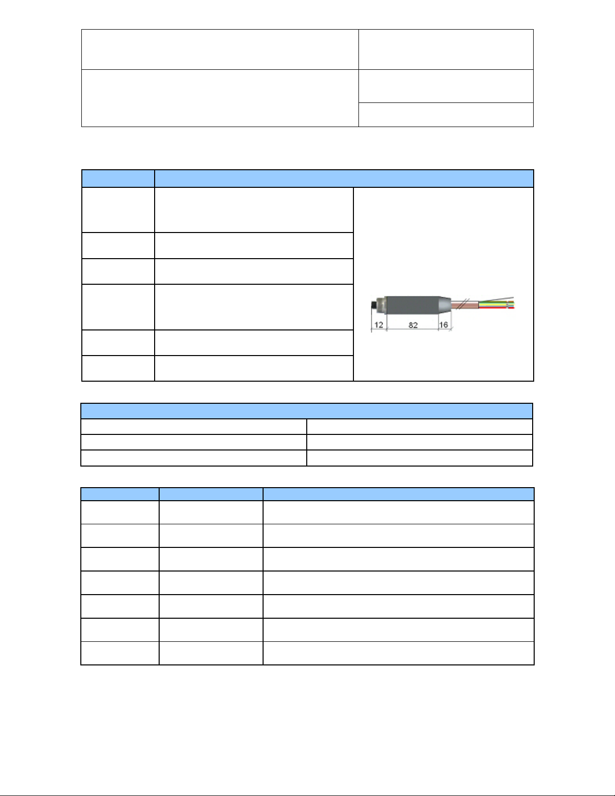
E2-F3A
E3-F3A
0.3 m (1 ft) extension cable (black) HC2 to
instrument with standard 7-pin female / male
connectors and wall mounting bracket for the
HC2-S probe
Document Type
1 m (3.2 ft) extension cable (black) HC2 to
E2-01A
E3-01A Same as E2-01A with white cable
instrument with standard 7-pin female / male
connectors. Barrel length 82 mm (3.2”)
2 m (6.5 ft) extension cable (black) HC2 to
E2-02A
E3-02A Same as E2-02A with white cable
E2-05A
E3-05A Same as E2-05A with white cable
Order Code Description
E2-02AS Same as E2-02A, but with short barrel
E3-02AS Same as E3-02A, but with short barrel
NOTES:
o Al l white cables use PUR insulation (sunlight resistant)
o See also: Maximum temperature limit for connectors, cables and adapters
instrument with standard 7-pin female / male
connectors
5 m (16.4 ft) extension cable (black) HC2 to
instrument with standard 7-pin female / male
connectors
© 2009-2010; Rotronic AG E-M-HC2-accessories_23
Page 6
E-M-HC2-accessories_24
See: Wiring color code
Wire color
Name
Function
Document code Unit
Rotronic AG
Bassersdorf, Switzerland
Accessories and Parts
for probes, indicators and transmitters
Document title
Page
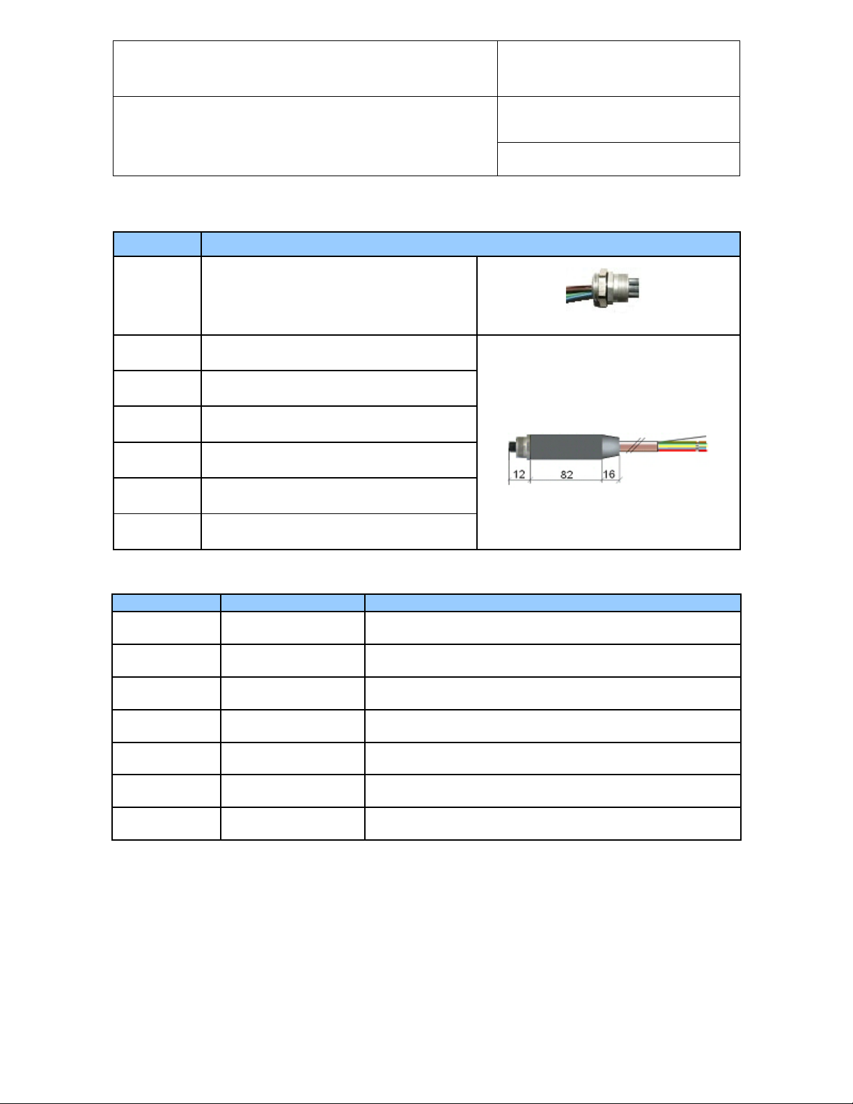
4.2 Passive cables and connectors for OEM applications
Order Code Description
E2-XX
E2-01XX
E2-02XX Same as E2-01XX with 2m (6.5 ft) cable
E2-05XX Same as E2-01XX with 5m (16.4 ft) cable
E3-01XX
E3-02XX Same as E3-01XX with 2m (6.5 ft) cable
E3-05XX Same as E2-01XX with 5m (16.4 ft) cable
Female connector for panel mount with 7
wires (0.3 m / 1ft), tinned ends
Female connector (black), 1 m (3.2 ft) cable
with tinned ends
Female connector (white), 1 m (3.2 ft) cable
with tinned ends
See: Wiring color code
Instruction Manual
Document Type
6 of 23
See also: Maximum temperature limit for connectors, cables and adapters
Green VDD (+) 3.2 to 5 VDC
Grey GND Power and digital signal
Red RXD UART
Blue TXD UART
White Out 1 analog (+) Humidity 0…100%RH (default) or calculated parameter
Brown Out 2 analog (+) Temperature -40…60°C (default)
Yellow AGND (-) Analog signal ground
Shielded cables with tinned ends: the shield is ended as a non-insulated wire connected to GND at the
connector level
© 2009-2010; Rotronic AG E-M-HC2-accessories_23
Page 7
E-M-HC2-accessories_24
connect the two terminal boxes.
Wire color
Description
White
RS485_N_Tx
Blue
RS485_P_Tx
Brown
RS485_N_Rx
Red
RS485_P_Rx
Green
VDD (+) / 3.3 VDC
Gray
GND
white
White
Blue
Brown
Red
Green
Gray
max. 100 m / 330 ft
Probe side
Transmitter side
Document code Unit
Rotronic AG
Bassersdorf, Switzerland
Accessories and Parts
for probes, indicators and transmitters
Document title
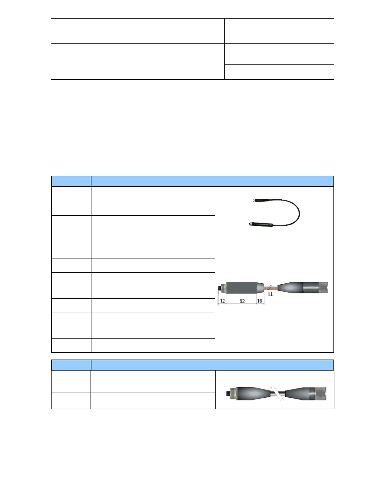
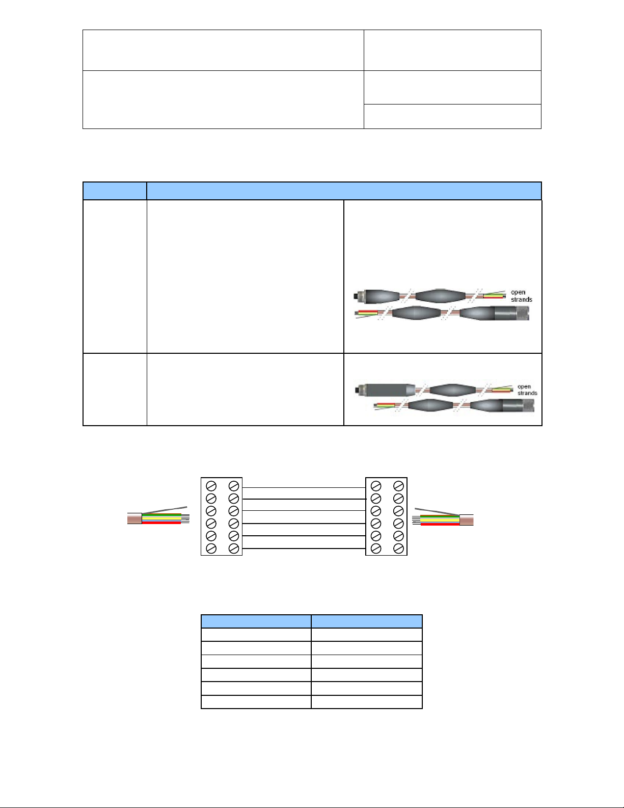
4.3 Cables with digital signal booster
Order Code Description
Active digital signal booster set
Allows connecting a HC2 probe to a
transmitter over a distance of up to 100 m
(330 ft). The probe analog signals are not
transmitted by the AC3003.
AC3003
AC3003-L
Open strands with tinned ends designed for
connection via two customer supplied
terminal boxes. The strands are to be wired
in parallel, e.g. 1:1
Use a shielded cable with twisted pairs to
Same as AC3003, but with long barrel on
probe side.
Instruction Manual
Document Type
Page
7 of 23
NOTE:
Power consumption: 4.8 mA
o See also: Maximum temperature limit for connectors, cables and adapters
© 2009-2010; Rotronic AG E-M-HC2-accessories_23
Page 8
E-M-HC2-accessories_24
UART to USB adapter cable
Power is provided by USB port
UART to RS232 adapter cable
Requires AC adapter mod. AC1207 (9VDC)
Document code Unit
Rotronic AG
Bassersdorf, Switzerland
Accessories and Parts
for probes, indicators and transmitters
Document title
Instruction Manual
Page
8 of 23
Document Type
5 Digital interface adapters for the HC2 probe s
NOTE:
o Supply voltage to the probe: 3.3 VDC ± 0.1 VDC
o See also: Maximum temperature limit for connectors, cables and adapters
5.1 USB adapter
Order Code Description
AC3001
IMPORTANT:
o Prior to using cable AC3001, the ROTRONIC USB driver must be installed on the PC. Both the driver
and the in stallation instructions (document E-M-HW4v3-Main) are located on the HW4 CD.
Connects HC2 probe to PC running HW4
5.2 RS-232 adapter
Order Code Description
AC3002
Connects HC2 probe to PC running HW4
5.3 Ethernet adapter
Order Code Description
UART to Ethernet (TCP/IP) adapter
Connects HC2 probes to Ethernet network
AC3005
IMPORTANT:
o Prior to using cable AC3005, the TCP/IP settings of the cable must be configured by the user to be
compatible with the local area network. Detailed instructions are provided separately in documents
E-M-HW4v3-Main and E-M-TCPIP-Conf. Devices with an Ethernet interface are shipped with a Device
Configuration Certificate that provides information about the factory configuration settings.
Power supply options:
AC adapter mod. AC1207 (9VDC)
or PoE (IEEE 802.3af compliant)
© 2009-2010; Rotronic AG E-M-HC2-accessories_23
Page 9

E-M-HC2-accessories_24
Female connector (black) for HC2 probes with
See note below
Specifications
Supply voltage to adapter
5.0…28 VDC
Supply voltage to probe
3.3 VDC
Current consumption (includes HC2 probe)
10 mA typical
Wire color
Name
Function
Document code Unit
Rotronic AG
Bassersdorf, Switzerland
Accessories and Parts
for probes, indicators and transmitters
Document title
5.4 RS-485 and Modbus adapters
Order Code Description
1 m (3.2 ft) cable (4 wires with tinned ends):
Powers the HC2 probe and allows connecting
E2-01XX-MOD
E2-02XX-MOD Same as E2-01XX-MOD with 2m (6.5 ft) cable
E2-05XX-MOD Same as E2-01XX-MOD with 5m (16.4 ft) cable
the probe to either a RS-485 network or a
Modbus network, depending on the
communication protocol used by the probe
Instruction Manual
Page
9 of 23
Document Type
RS-485 specifications Baud rate : 19200
Green VDD (+) Power supply +
Grey GND Power and digital signal
Red RXD RS-485 bi-directional TX+ / RX +
Blue TXD RS-485 bi-directional TX- / RX -
NOTE: The electronic circuit of the adapter generates a small amount of heat. For this reason, do not place
the adapter directly under the probe. Depending on the application, using a passive cable to separate the
adapter and the HC2-S or HC2-S3 probe is recommended to prevent heat transfer from the adapter to the
probe and obtain the best measurement accura cy .
Parity : none
Data bits : 8
Stop bits : 1
© 2009-2010; Rotronic AG E-M-HC2-accessories_23
Page 10

E-M-HC2-accessories_24
Document code Unit
Rotronic AG
Bassersdorf, Switzerland
Accessories and Parts
for probes, indicators and transmitters
Document title
Instruction Manual
Page
10 of 23
Document Type
Networking notes:
o A Modbus network and a RS-485 network are physically identical but cannot be mixed due to the
difference between the communicatio n pr otoc ol s.
o The internal configuration of the HC2 probe determines which communication protocol (RO-ASCII or
Modbus) will be used by the combination of probe and adapter. RO-ASCII is the factory default
communication protocol for the HC2 probe and is automatically used whenever the probe is interrogated
by the HW4 software.
The protocol used by the probe when not communicating with HW4 can be changed between RO-ASCII
and Modbus with the HW4 software > Device Manager. After interrogating or configuring the probe with
HW4, cycle power to the probe to enable the selected protocol.
o When connecting the probe to a RS-485 network be sure that the probe is configured to use the RO-ASCII
protocol.
o RS-485 Compatibility: the RO-ASCII protocol is not compatible with the protocol used by the previous
generation of ROTRONIC products. Do not connect legacy products and the adapter / HC2 probe
combination to the same RS-485 multi-drop network.
o Within a RS-485 network, the combination of HC2 probe and adapter is always seen as a slave. The RS-
485 address is that of the HC2 probe. The factory default is address 0. The master is another ROTRONIC
device with an interface combination such as RS-485 and USB or RS-485 and TCP/IP.
Please note that each device connected to a RS-485 networ k , includ ing the ma ster dev ice , must have a
unique address. As long as the factory default address of the HC2 probe (0) has not been changed, the
HW4 software will automatically change the address of the probe to the next available address at the time
that the probe is added as a slave to a RS-485 network monitored by HW4.
The RS-485 address of the HC2 probe can also be changed manually with the HW4 software Device
Manager.
o Each adapter can be powered either by an individual voltage source or centrally powered from the network
with a single voltage source. In the case of a network that both provides power and transmits data, a
shielded cable with two twisted pairs is required for the main bus.
o User to supply all necessary connecting hardware such as T-connection box, terminal box, etc.
o Prior to using the adapter, we strongly recommend consulting the following documents:
E-M-HW4v3-Main, E-M-HW4v3-F2-001 and E-M-AC3000-CP
© 2009-2010; Rotronic AG E-M-HC2-accessories_23
Page 11

E-M-HC2-accessories_24
UART to USB adapter cable
separately
Separate power supply for probe
Document code Unit
Rotronic AG
Bassersdorf, Switzerland
Accessories and Parts
for probes, indicators and transmitters
Document title
Instruction Manual
Page
11 of 23
Document Type
6 Digital interface adapte r for the HC2-S3C0 probe
6.1 USB adapter
Order Code Description
Connects HC2-S3C0 probe to PC running
HW4 (this cable is supplied with a terminal
block which allows connecting the probe)
AC3001-XX
IMPORTANT:
o Prior to using cable AC3001-XX, the ROTRONIC USB driver must be installed on the PC. Both the driver
and the in stallation instructions (document E-M-HW4v3-Main) are located on the HW4 CD.
Power for the adapter electronics is provided
by USB port
Power to the probe must be supplied
Note : the maximum cable length for transmitting the digital signal to and from the probe UART interface
(RX and TX) is 5 meters.
© 2009-2010; Rotronic AG E-M-HC2-accessories_23
Page 12

E-M-HC2-accessories_24
Allows connecting up to 64 RS-485 slave
require a power supply.
Wire color
Function
Red
TX+ / RX+ (RS-485 bidirectional)
Blue
TX- / RX- (RS-485 bidirectional)
Green
V+ (optional connection)
Drain (shield)
GND (optional connection)
Document code Unit
Rotronic AG
Bassersdorf, Switzerland
Accessories and Parts
Instruction Manual
for probes, indicators and transmitters
Document title
Page
12 of 23
7 RS-485 converters and junction boxes
7.1 USB / RS-485 converter
Use the AC3010 converter with:
o HF45
o HF53 with digital option
o HF55
o HF65
o HF8 with RS-485 port
IMPORTANT:
1) Do not use the AC3010 with legacy devices or with the HygroLog HL-NT
2) Prior to using the AC3010, the ROTRONIC USB driver must be installed on the PC (available from
the HW4 CD or from www.rotronic-humidity.c om). For installation instructions see document
E-M-HW4v3-Main (§ 7.3).
Order Code Description
Document Type
AC3010
devices to a USB port The AC3010 itself
does not count as a device on the RS-485
network and does not have a RS-485 address
The AC3010 converter cable is powered
directly from the USB port and does not
© 2009-2010; Rotronic AG E-M-HC2-accessories_23
Page 13

E-M-HC2-accessories_24
Addr. 1
V +
GND
USB port (PC)
TX- / RX-
Separate
Addr. 1
240 Ω
V +
RS-485 Main Data Line (max. 100 m / 330 Ft)
Addr. n
TX- / RX-
Document code Unit
Rotronic AG
Bassersdorf, Switzerland
Accessories and Parts
for probes, indicators and transmitters
Document title
Instruction Manual
Page
13 of 23
Document Type
7.1.1 Powering the networked devices from the RS-485 main data line
Depending on the model, the devices connected to a RS-485 network can be powered from the main data line
as opposed to each device being powered separately. Please check the instruction manual of each device
The AC3010 offers the following options to power devices from the main data line:
a) Power directly from the USB port
Cable AC3010 has two wires (V+ and GND) that can be used to power the networked devices directly from
the USB port (5 VDC, 100 mA). In addition to the limit of 100 mA, the length of the main data line should not
exceed 100 m / 330 Ft.
Cable AC3010
Master Substitute
Does not have an
address
TX+ / RX+
GND
USB port (PC)
240 Ω
b) Power from a separate voltage source
When the networked devices are not powered from the USB port, the length of the main data line can be up to
1000 m / 3300 Ft.
Cable AC3010
Master Substitute
Does not have an
address
TX+ / RX+
RS-485 Main Data Line (max. 1000 m / 3300 Ft)
240 Ω
Addr. n
240 Ω
Voltage
Source
.
© 2009-2010; Rotronic AG E-M-HC2-accessories_23
Page 14

E-M-HC2-accessories_24
VDC external power supply.
Document code Unit
Rotronic AG
Bassersdorf, Switzerland
Accessories and Parts
for probes, indicators and transmitters
Document title
Instruction Manual
Page
14 of 23
Document Type
7.1.2 RS-485 network design and installation
Please follow the instructions provided in doc ume nt E-DV04-RS485.01
o Limit the RS-485 network to a single main data line (one segment)
o Terminate each end of the main data line with a 240 Ohm resistor. Termination resistors should be placed
only at the extreme ends of the data line, and no more than two terminations should be placed in any
single segment of an RS-485 network
o The total length the T connections should be included in the limit set for the main data line
(100 m or 1000 m)
o Do not connect more than 64 devices to the same main data line
o Each device connected to the RS-485 network should be given a unique address (1 to 64)
7.2 Ethernet / RS-485 converter
Use with:
o Any AirChip 3000 device that has a RS-485 port
o Docking stations for the HygroLog HL-NT
o Any legacy device that has a RS-485 port
IMPORTANT:
1) Use of the AC3011 requires a PC with the HW4 software version 2.4.0 or higher. The HW4 software
includes an Ethernet Configuration Tool that can be used to make the TCP/IP settings of the AC3011
converter compatible with the LAN to which the HW4 PC is connected For add itio nal information see
documents E-M-HW4v3-Main (§ 7.4 and § 11.2) and IN-E-TCPIP-Conf.
2) The AC3011 converter allows mixing both AirChip 3000 and legacy devices within the same RS-485
network as long as all devices use the same Baud rate (19200)
Order Code Description
AC3011
Allows connecting up to 64 RS-485 slave
devices to an Ethernet port (PC or LAN).
The AC3011 has an IP address but no RS485 address and does not count as one of the
devices on the RS-485 networ k.
The AC3011 converter requires a 12 to 24
© 2009-2010; Rotronic AG E-M-HC2-accessories_23
Page 15

E-M-HC2-accessories_24
Specifications
slave devices when mA rating is sufficient)
Current consumption (AC3011 only)
85 mA typical
Temperature operating range
-40…85°C
RS-485 specifications
Baud rate : 19200
Stop bits : 1
Terminal Block K1 (Power)
Function
K1-1
GND: Supply voltage (-) to AC3011
K1-2
V + :Supply voltage (+) to AC3011 – 12 to 24 VDC
K1-3
Earth Ground : Safety ground
Terminal Block K3 (RS-485)
Function
K3-4
D - : TX- / RX- (RS-485 bidirectional)
K3-3
D +: TX+ / RX+ (RS-485 bidirectional)
K3-2
GND: Supply voltage (-) to RS-485 data line (optional)
K3-1
V + : Supply voltage (+) to RS-485 data line – 12 to 24 VDC (optional)
Document code Unit
Rotronic AG
Bassersdorf, Switzerland
Accessories and Parts
for probes, indicators and transmitters
Document title
Instruction Manual
Page
15 of 23
Document Type
Supply voltage to AC3011 converter 12…24 VDC (can be used to power the RS-485
Parity : none
Data bits : 8
7.2.1 RJ-45 Connector and terminal blocks
The RJ-45 connector is accessible without having to open the AC3011 enclosure.
© 2009-2010; Rotronic AG E-M-HC2-accessories_23
Page 16

E-M-HC2-accessories_24
Addr. n
V +
GND
Ethernet
D+
D-
V +
GND
Voltage
Source
Addr. 1
V +
GND
Addr. n
Separate
Ethernet
D-
GND
V +
Voltage
Source
RS-485 Main Data Line (max. 1000 m / 3300 Ft)
RS-485 Main Data Line (max. 1000 m / 3300 Ft)
Document code Unit
Rotronic AG
Bassersdorf, Switzerland
Accessories and Parts
for probes, indicators and transmitters
Document title
Instruction Manual
Page
16 of 23
Document Type
7.2.2 Powering the networked devices from the RS-485 main data line
Depending on the model, the devices connected to a RS-485 network can be powered from the main data line
as opposed to each device being powered separately. Please check the instruction manual of each device
The AC3011 offers the following options to power devices from the main data line:
a) Power from the same source as the AC3011
This option can be used only when the mA rating of the power supply used for the AC3011 is sufficient to
power both the AC3011 and the networked devices.
AC3011
Converter
No RS-485
Address
240 Ω
Addr. 1
b) Power from a separate voltage source
AC3011
Converter
No RS-485
Address
D+
Voltage
Source
240 Ω
.
240 Ω
240 Ω
© 2009-2010; Rotronic AG E-M-HC2-accessories_23
Page 17

E-M-HC2-accessories_24
RJ45
Dimensions in mm
Document code Unit
Rotronic AG
Bassersdorf, Switzerland
Accessories and Parts
for probes, indicators and transmitters
Document title
Instruction Manual
Page
17 of 23
Document Type
7.2.3 RS-485 network design and installation
Please follow the instructions provided in doc ume nt E-DV04-RS485.01
o Limit the RS-485 network to a single main data line (one segment)
o Terminate each end of the main data line with a 240 Ohm resistor. Termination resistors should be placed
only at the extreme ends of the data line, and no more than two terminations should be placed in any
single segment of an RS-485 network
o The total length the T connections should be included in the limit set for the main data line
(100 m or 1000 m)
o Do not connect more than 64 devices to the same main data line
o Each device connected to the RS-485 network should be given a unique address (1 to 64)
7.2.4 Dimensional drawings
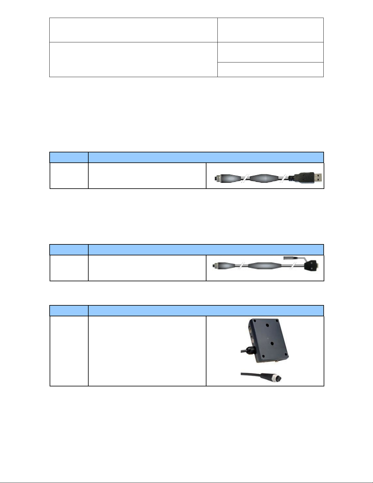
7.3 Junction box for RS-485 networks
The AC3021 is a wall mounted junction box designed to facilitate the connection of devices to a RS-485 main
data line.
Order Code Description
AC3021
Passive junction box for RS-485 networks,
designed for wall mounting
© 2009-2010; Rotronic AG E-M-HC2-accessories_23
Page 18

E-M-HC2-accessories_24
Specifications
Temperature limits
-40…85°C
jumper
Connection type
T2 or T3
Document code Unit
Rotronic AG
Bassersdorf, Switzerland
Accessories and Parts
for probes, indicators and transmitters
Document title
Instruction Manual
Page
18 of 23
Document Type
Built-in resistor for terminating main data line 240 Ohm, can be connected or disconnected with a
7.3.1 Principle diagram
Junction box AC3021 allows the following connections:
D +: TX+ / RX+ (RS-485 bidirectional)
D - : TX- / RX- (RS-485 bidirectional)
V + : Supply voltage (+) via RS-485 data line
GND: Supply voltage (-) via RS-485 data line
Shield: RS-485 data line shield
© 2009-2010; Rotronic AG E-M-HC2-accessories_23
Page 19

E-M-HC2-accessories_24
Document code Unit
Rotronic AG
Bassersdorf, Switzerland
Accessories and Parts
for probes, indicators and transmitters
Document title
Page
8 Mounting hardware
8.1 Mounting hardware for through-wall probe installation
Order Code Description
Mounting flange with compression fitting for
(15 mm / 0.6” diameter probe).
AC5005
AC5001
Use for though wall installation of the HF4
type D
Maximum temperature 100 °C (212°F)
Sleeve for adapting a 15 mm / 0.6” diameter
probe to a 25 mm / 1.0 “ diameter throughwall mounting hole (HF42 and HF43 type D,
vertical mounting position)
Facilitates the replacement of older products
with a 25 mm probe diameter
Instruction Manual
Document Type
19 of 23
Order Code Description
AC1303-M
AC1304-M
AC1305
AC1306
Compression fitting for 15 mm (1.0”) diameter
probes. Maximum temperature 200 °C (392°F)
Compression fitting for 25 mm (0.6”) diameter
probes. Maximum temperature 200 °C (392°F)
Flange for AC1303-M – nickel coated stee l
Diameter: 80 mm (3.1”)
Flange for AC1304-M – nickel coated stee l
Diameter: 80 mm (3.1”)
© 2009-2010; Rotronic AG E-M-HC2-accessories_23
Page 20

E-M-HC2-accessories_24
Document code Unit
Rotronic AG
Bassersdorf, Switzerland
Accessories and Parts
for probes, indicators and transmitters
Document title
Instruction Manual
Page
20 of 23
Document Type
8.2 Mounting hardware for transmitter enclosure
Use with:
o HF4
o HF5
o HF6
Order Code Description
DIN-rail mounting kit consisting of 2 clamps
that attach to the back of the enclosure with
AC5002
the screws provided.
DIN-rail (35 mm / 1 3/8”) not included
9 Calibration accessories
Order Code Description
EA00-SCS 0.5 %RH humidity std, SCS cert., pack of 5
EA05-SCS 5 %RH humidity std, SCS cert., pack of 5
EA10-SCS 10 %RH humidity std, SCS cert., pack of 5
EA20-SCS 20 %RH humidity std, SCS cert., pack of 5
EA35-SCS 35 %RH humidity std, SCS cert., pack of 5
EA50-SCS 50 %RH humidity std, SCS cert., pack of 5
EA65-SCS 65 %RH humidity std, SCS cert., pack of 5
EA80-SCS 80 %RH humidity std, SCS cert., pack of 5
EA95-SCS 95 %RH humidity std, SCS cert., pack of 5
ER-15 Calibration device for 15mm diameter probes
ER-05 Calibration device for 5mm diameter probes
EM-G Calibration device for type ‘IE’ probes
For instructions regarding the ROTRONIC humidity standards and calibration devices see document
E-M-CalBasics.
© 2009-2010; Rotronic AG E-M-HC2-accessories_23
Page 21

E-M-HC2-accessories_24
Document code Unit
Rotronic AG
Bassersdorf, Switzerland
Accessories and Parts
for probes, indicators and transmitters
Document title
10 Dust filters
10.1 Spare filters
Order Code Use with Slotted cap Filter insert
NSP-PCB-PE
NSP-PCB-WM
NSP-PCB-TF
NSP-PCW-PE
NSP-PCW-WM
NSP-PCW-TF
NSP-PCG-PE
NSP-PCG-WM
NSP-PCG-TF
Order Code U se with Filter Material
HC2-S
HF4
HF6 wall mount
HP21
HC2-S3
HF3
Polycarbonate,
black
Polycarbonate,
white
Polycarbonate,
grey
Polyethylene
Wire mesh
Teflon
Polyethylene
Wire mesh
Teflon
Polyethylene
Wire mesh
Teflon
Instruction Manual
Document Type
Page
21 of 23
ET-Z10
Order Code Use with Description
SP-T05
HC2-HP28
HC2-HP50
H2C-C05 Teflon filter
Sintered steel
© 2009-2010; Rotronic AG E-M-HC2-accessories_23
Page 22

E-M-HC2-accessories_24
Document code Unit
Rotronic AG
Bassersdorf, Switzerland
Accessories and Parts
for probes, indicators and transmitters
Document title
10.2 Dust filter parts
Order Code Use with Description
HC2-HK
NSP-ME
SP-MSB15
SP-M15
HC2-HP
HC2-IC
HF6 duct / cable
HC2-IM
HC2-IE
HF7
NSP-ME
SP-MSB15
Filter base Nickel plated brass
HC2 thread
Filter Cartridge not included
Filter base Nickel plated brass
HC1 thread
Filter Cartridge not included
Wire mesh filter cartridge
Use with NSP-ME or SP-MSB15
Instruction Manual
Document Type
Page
22 of 23
SP-S15
SP-T15
NSP-ME
SP-MSB15
NSP-ME
SP-MSB15
Sintered steel filter cartridge
Use with NSP-ME or SP-MSB15
Teflon filter cartridge
Use with NSP-ME or SP-MSB15
© 2009-2010; Rotronic AG E-M-HC2-accessories_23
Page 23

E-M-HC2-accessories_24
Added AC3011 converter and AC3001-XX UART to USB
adapter cable
Document code Unit
Rotronic AG
Bassersdorf, Switzerland
Accessories and Parts
for probes, indicators and transmitters
Document title
Instruction Manual
Page
23 of 23
Document Type
11 Maximum temperature limit for connectors, cables and
adapters
• Cables and wiring: 70°C (158°F)
• All probe side connectors: 100 °C (212 °F)
• All other connectors (USB, mi ni-USB, D-Sub 9 or RJ45: 70°C (158°F)
NOTES:
o Probe side connectors have a maximum temperature limit of 100 °C so as to permit full immersion of the
HC2-S probe into a hot environment. However the cable itself should not be subjected to temperature
higher than 70 °C.
o Operating temperature limits of all electronic circuits used for cables and adapters: -40…85 °C
(-40…185 °F)
12 Document releases
Doc. Release Date Notes
_20 Apr.11, 2009 Original release
_21 Feb. 23, 2010
_22 Mar. 16, 2010 Added AC3021 junction box for RS-485 networks
_23 Jun. 18, 2010 Updated document for HW4 Software v.3
_24 Feb. 14, 2013 Added power consumption of AC3003
© 2009-2010; Rotronic AG E-M-HC2-accessories_23
 Loading...