

Page 1
IN-E-DS-U4WEB-V1_14
Document code Unit
Rotronic AG
Bassersdorf, Switzerlan d
Docking station DS-U4WEB with web
server version 1: instruction manual
Document title
Instruction Manual
Document Type
Page
1 of 15
Docking Station DS-U4WEB with web server version 1
Instruction Manual
© 2007; Rotronic AG IN-E-DS-U4WEB-V1_14
Page 2

IN-E-DS-U4WEB-V1_14
Document code Unit
Rotronic AG
Bassersdorf, Switzerlan d
Docking station DS-U4WEB with web
server version 1: instruction manual
Document title
Instruction Manual
Document Type
Page
2 of 15
Table of contents
1 Overview ................................................................................................................................ 3
Description ............................................................................................................................ 3
2
Connector identification ...................................................................................................... 3
2.1
Probe inputs ........................................................................................................................ 4
2.2
Logical inputs (on / off) ....................................................................................................... 5
2.3
Pin-out diagrams ................................................................................................................ 5
2.4
Operating limits ................................................................................................................... 5
2.5
Installation ............................................................................................................................. 6
3
ROTRONIC device configuration certificate ...................................................................... 7
4
Baud rate compatibility requirements ................................................................................ 8
5
Configuration of the internal Eth ernet module .................................................................. 8
6
Other configuration settings ................................................................................................ 9
7
Web Server .......................................................................................................................... 10
8
Web Server pages and files ............................................................................................. 10
8.1
Additional informat ion ....................................................................................................... 13
8.2
Performing a flash update .................................................................................................. 14
9
Document releases ............................................................................................................. 15
10
Applicability:
This manual is valid for docking stations with firmware version 1.4 or higher, a nd with web server
version 1.0 or higher. Changes to the last digit of the version number reflect minor changes that
do not affect the manner in which the instrument should be operated.
© 2007; Rotronic AG IN-E-DS-U4WEB-V1_14
Page 3
IN-E-DS-U4WEB-V1_14
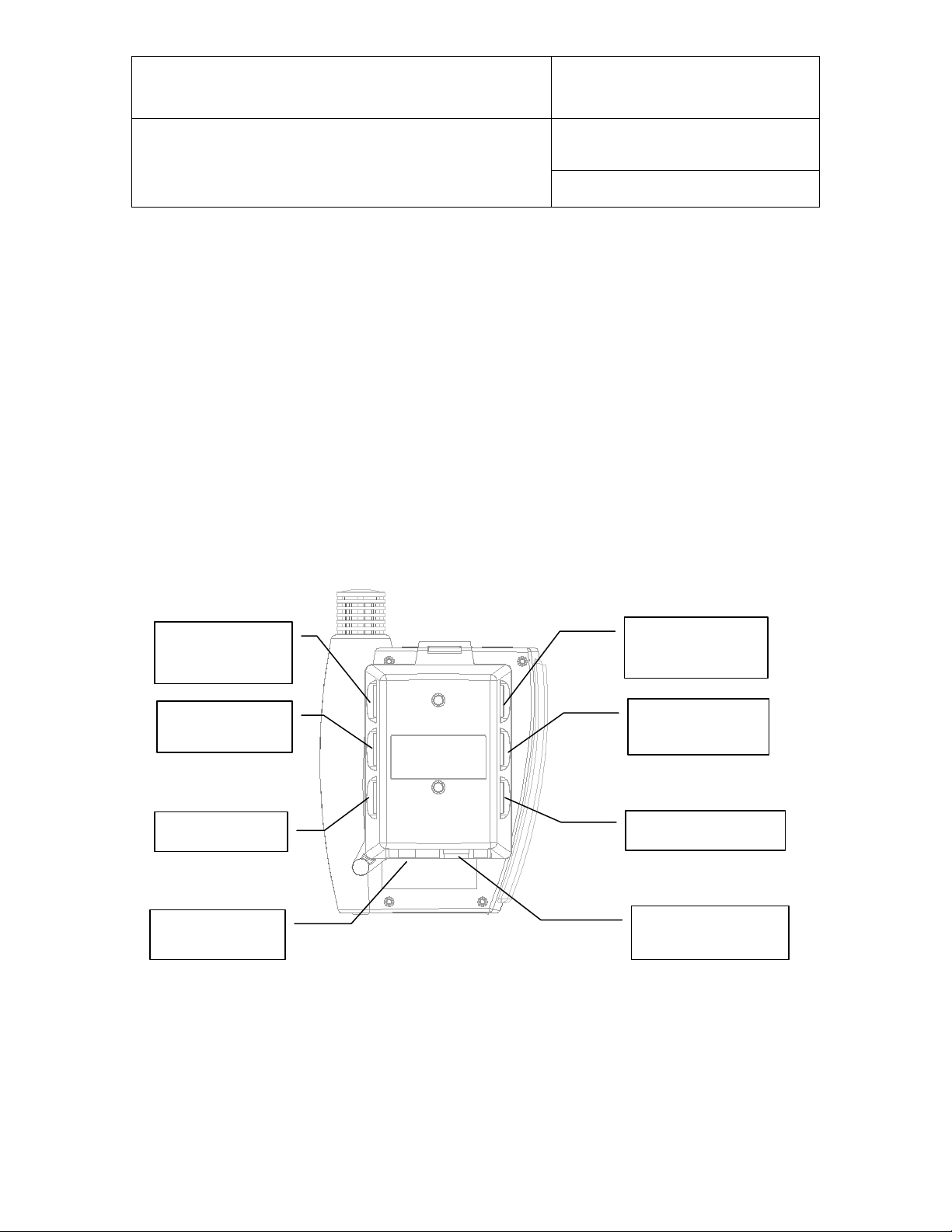
Probe input 4
Probe input 5
Logical inputs
Probe input 6
RJ45
Not Used
12VDC Power
Document code Unit
Rotronic AG
Bassersdorf, Switzerlan d
Docking station DS-U4WEB with web
server version 1: instruction manual
Document title
Instruction Manual
Document Type
Page
3 of 15
1 Overview
Docking station model DS-U4WEB allows connection of the HygroLog NT data logger to an
Ethernet local area network (TCP/IP) and communication with a PC with the ROTRONIC HW4
software installed. This docking station has 4 probe inputs and 2 digital inputs that can be used to
monitor a contact.
The DS-U4WEB also features a Web Server that can be accessed directly from a standard web
browser just like any web site by typing the IP address of the docking station. This Web Server
can display current measurement data, schedule recording by the data logger, download log files
and configure both the data logger and docking station from any PC, even a PC on which the
HW4 software has not been installed. The Web Server can also generate a number of XML
pages which allow data integration into other applications.
2 Description
2.1 Connector identification
(+) center
Probe input 7
© 2007; Rotronic AG IN-E-DS-U4WEB-V1_14
Page 4

IN-E-DS-U4WEB-V1_14
Document code Unit
Rotronic AG
Bassersdorf, Switzerlan d
Docking station DS-U4WEB with web
server version 1: instruction manual
Document title
Instruction Manual
Document Type
Page
4 of 15
2.2 Probe inputs
Depending on the model of docking station, the signals from up to 4 additional probes can be
processed by the HygroLog NT. These probes can be either HygroClip digital probes or analog
probes (including pres sur e pr obes) . An y input used tog ether with an ana lo g probe s houl d be
configured with the ROTRONIC HW4 software. Detailed configuration instructions are provided in
document IN-E-DS-Aconf_10.doc.
HygroClip probes
An adapter cable is required to connect a probe to inputs 4, 5, 7 and 7 of the docking station. Use
cable MOK-02-B5 (or similar) for probes with a 5-pi n DAT-05 connector. Use cable T7-03-B5 (or
similar) for probes with a 7-pin T7 connector.
Analog and pressure probes
The probe inputs of a docking station can be configured to accept an analog probe. Analog
probes cannot be used with the probe inputs of the HygroLog NT and these inputs are designed
for use with the HygroClip probes only. An analog probe can be used to measure with the
HygroLog NT a parameter other than humidity or temperature. For example, an analog pressure
probe may used to provide the value of barometric pressure required for the calculation of
parameters such as the wet bulb temperature, mixing ratio or enthalpy.
The following requirements and restrictions apply to analog probes:
● ROTRONIC analog humidity-temperature probes with the standard temperature output signal of
– 0.5…2.0 V = -50…200°C: because the HygroLog NT cannot read a negative voltage signal,
temperature measurement is generally limited to values above freezing.
● Third-party analog probes: single channel probes (one signal), voltage output signal within the
range of 0 to 2.5 VDC, supply voltage: 7.6…9 VDC (direct from the HygroLog NT battery) or 12
VDC when using an AC adapter, maximum current consumption: 10 mA.
Docking station model DS-U4-4-20 accepts up to four 3-wire single channel analog probes with
a 4-20 mA current output signal. Each probe input uses an internal 150 Ohm resistor to convert
4…20 mA to 600…3000 mV (nominal). The HW4 software allows a 2-point adjustment of the
mA to mV conversion to compensate for the tolerance on the 150 Ohm resistor (use Device
Manager in HW4). The probes are powered by the docking station (supply voltage: 7.6…9
VDC (direct from HygroLog NT battery) or 12 VDC when using an AC adapter, maximum
current draw: 10 mA / probe). It is also possible to use a 2-wire single channel probe but in that
case only one probe can be connected to the docking station (use any of the two probe inputs).
Connecting two 2-wire probes at the same time would create a current loop and result in
erroneous measurements.
● Resolution is limited by the 10-bit A/D converter used for the analog inputs. This converter
provides a theoretical maximum of 1024 counts for an input voltage span of 2.5 VDC. In theory,
this gives a resolution of 2.5 / 1024 = 0.00244 V. In practice, it is not possible to get 100% of
the counts from an A/D converter and the actual resolution should be about 0.0027 V (typical).
For example, if a probe with a temperature signal of 0...1V = 0…100°C is being used, the
signal resolution will be about 100 x 1 x 0.0027 = 0.27°C
© 2007; Rotronic AG IN-E-DS-U4WEB-V1_14
Page 5
IN-E-DS-U4WEB-V1_14
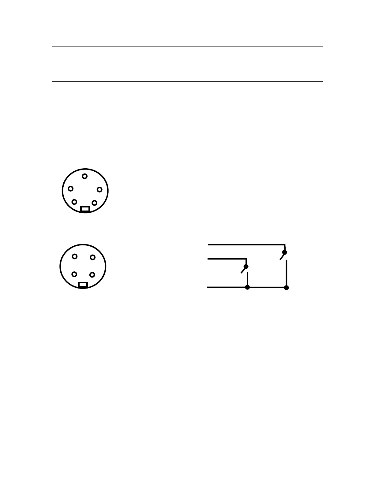
4
2
1
1: + 3.5 VDC
1
2
GND: not used (eventually use for a shield)
+3.5 V
Note: an internal pull-down resistor sets
3
4
2
Inputs 4, 5, 6 and 7 - solder side of matching male connector
1: not used
Document code Unit
Rotronic AG
Bassersdorf, Switzerlan d
Docking station DS-U4WEB with web
server version 1: instruction manual
Document title
Instruction Manual
Document Type
Page
5 of 15
2.3 Logical inputs (on / off)
Several models of docking station allow the HygroLog NT to process up to 2 logical inputs.
Typically this is used to monitor a relay contact, a door contact, etc.
2.4 Pin-out diagrams
2: power (DC+)
3: GND (docking station) / analog (-)
4: DIO
5: analog signal (+)
1
Logical inputs - solder side of matching male connector
5
3
2: Input 1
3: Input 2
4: GND
each input to 0 when the contact is open.
Logical Thresholds: logical 1: ≥ 2.8 VDC, logical 0: ≤ 0.7 VDC
2.5 Operating limits
The docking station operating limits are the same as for the HygroLog NT data logger:
HygroLog NT without display:
● -10…50°C with the factory supplied alkaline batt ery
● -30…70°C with a lithium battery or an external AC adapter
HygroLog NT with display:
● -10…50°C with the factory supplied alkaline battery
● -10…60°C with a lithium battery or an external AC adapter
The HygroClip probes have generally wider operating limits (see individual probe specifications).
© 2007; Rotronic AG IN-E-DS-U4WEB-V1_14
Page 6

IN-E-DS-U4WEB-V1_14
To mount the docking station to a wall, use
so as to match the
[B]
[B]
[A]
Document code Unit
Rotronic AG
Bassersdorf, Switzerlan d
Docking station DS-U4WEB with web
server version 1: instruction manual
Document title
3 Installation
the two holes shown on the right. The
HygroLog NT can then be attached to the
docking station as explained below.
To attach the HygroLog NT to the
docking station:
Place the HygroLog NT on the
docking station
two areas [A]. Press lightly one
against the other and secure the
assembly with threaded pin [B].
Instruction Manual
Document Type
Page
6 of 15
When the docking station is
mounted on a wall, a small
padlock (not shown) may be put
through pin [B] to prevent removal
of the HygroLog NT from the
docking station.
© 2007; Rotronic AG IN-E-DS-U4WEB-V1_14
Page 7

IN-E-DS-U4WEB-V1_14
DHCP or Static Address
Static
IP Address
192.168.1.1
Subnet Mask
255.255.255.0
Default Gateway
192.168.1.0
TCP Port
2101
MAC Address
00:40:9D:28:2D:2A
Firmware Release (device)
1.4
Serial Port Configuration Prof ile
TCP Sockets
Basic Serial Settings
Baud Rate
57600
Data Bits
8 Parity
None
Stop Bits
1 Flow Control
None
Document code Unit
Rotronic AG
Bassersdorf, Switzerlan d
Docking station DS-U4WEB with web
server version 1: instruction manual
Document title
Instruction Manual
Document Type
Page
7 of 15
4 ROTRONIC device configuration certificate
ROTRONIC docking stations with an Ethernet interface (both wired and wireless) are shipped
with a Device Configuration Certificate that provides information about the factory configuration
settings, in particular the TCP/IP settings. See example below:
Setting Value
Note: the Baud rate setting of the DS-U4WEB internal Ethernet module cannot be changed and
is always 57600 bps. Consequently, any HygroLog NT used with this docking station should also
be set to a Baud rate of 57600 bps to enable communication between the logger and docking
station.
© 2007; Rotronic AG IN-E-DS-U4WEB-V1_14
Page 8

IN-E-DS-U4WEB-V1_14
Document code Unit
Rotronic AG
Bassersdorf, Switzerlan d
Docking station DS-U4WEB with web
server version 1: instruction manual
Document title
Instruction Manual
Document Type
Page
8 of 15
5 Baud rate compatibility requirements
The default factory Baud rate for both the HygroLog NT and docking stations with Ethernet
interface is 57600 bps.
Devices with mismatched Baud ra te will not communicate together. A Baud rate mismatch
can become an issue when an existing da ta log ger is u sed wit h a new docking station.
Prior to using an existing data logger with a new docking station, you should verify that the Baud
rate of the data logger is set to 57600 bps. On a data logger with display and keypad, the Ba ud
rate can be displayed by using the keypad: MENU > Instrument.
The Baud rate settings of the HygroLog NT can only be changed with the Device Manager
function (Digital Interface tab) available from within the HW4 software. Depending on the
situation, you may have to use a docking station with either an RS-232 (COM port) or USB
interface to connect the logger to the HW4 PC. Communication between the HygroLog NT and a
docking station with either RS-232 or USB interface is not affected by the baud rate of the data
logger.
6 Configuration of the internal Ethernet module
• Place a HygroLog NT on the docking station. Use an AC adapter to power both the data
logger and docking station.
IMPORTANT: Prior to using a new docking station with a previously configured data logger,
you should verify the Baud rate used by the data logger and, if necessary, use HW4 Device
Manager to change the Baud rate of the data logger to the factory standard of 57600 bps.
• Prior to connecting the docking station to the local area network, please read the Dev ice
Configuration Certificate supplied with the docking station as well as document
IN-E-TCPIP-Conf_11. This document provides detailed instruction for configuring the internal
Ethernet (TCP/IP) module of the docking station to make it compatible wit h your local area
network.
Notes:
• The utility Finder.exe is provided on the HW4 software CD. This utility can be used to
discover the internal Ethernet module of the DS-U4WEB docking station and changing its
TCP/IP settings. To start Finder.exe, double click on the file with the mouse. The following
password is required: Netsilicon
• The internal Ethernet module of the DS-U4WEB is not compatible with the Digi Device
Discovery utility mentioned in document IN-E-TCPIP-Conf_11
• Configuration of the TCP/IP settings can also be done with the docking station Web Server
(provided that the TCP/IP settings of the DS-U4WEB are compatible with the LAN to which
the docking station is attached and the IP address of the DS-U4WEB is known).
© 2007; Rotronic AG IN-E-DS-U4WEB-V1_14
Page 9

IN-E-DS-U4WEB-V1_14
Document code Unit
Rotronic AG
Bassersdorf, Switzerlan d
Docking station DS-U4WEB with web
server version 1: instruction manual
Document title
Instruction Manual
Document Type
Page
9 of 15
7 Other configuration settings
Either the HW4 software or the Web Server can be used to configure both the HygroLog NT data
logger and docking station. Unlike HW4, the Web Server does not generate an authent icate d
configuration protocol. For this reason, using HW4 should be the preferred configuration method.
With the exception of the TCP/IP settings and other settings of the docking station internal
Ethernet module, all configuration data is retained in the HygroLog NT non-volatile memory. In
particular, no input configuration data is retained in the docking station proper. Therefore, it is
important to observe the following:
• Prior to configuring the data logger and docking station with the HW4 software, we strongly
recommend enabling HW4 to generate and save protocols (see below). After using Device
Manager in HW4 to configure the data logger and docking station, print the configuration
protocol for your records. This protocol includes information that will eventually be usef ul
such as serial number and firmware version of the data logger, serial number and firmware
version of the docking station as well as detailed configuration settings (logger and docking
station).
• Search for the data logger with HW4 and use Device Manager to configure both the data
logger and any available probe or logical input of the docking station as required by the
intended application.
© 2007; Rotronic AG IN-E-DS-U4WEB-V1_14
Page 10

IN-E-DS-U4WEB-V1_14
Document code Unit
Rotronic AG
Bassersdorf, Switzerlan d
Docking station DS-U4WEB with web
server version 1: instruction manual
Document title
• Avoid separating a matched pair of data logger and docking station, especially when analog
probes are used with the docking station.
Instruction Manual
Document Type
Page
10 of 15
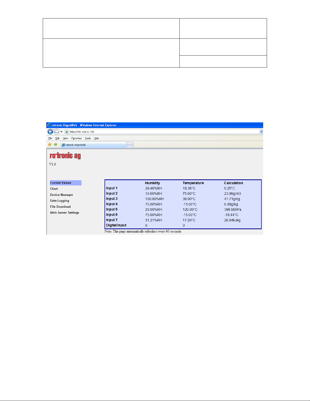
8 Web Server
Just like any web site, the docking station Web Server can be accessed with a standard web
browser, simply by typing the docking station IP address. Example: http://192.168.57.29
The Web Server navigator gives direct access to the following screens:
The contents of each screen are self explanatory and similar to the equivalent screens in the
HW4 software.
Note regarding the Chart page:
Depending on the communication speed with the DS-UAWEB docking station, Internet Explorer
may stop downloading the Chart page and display the following message box. When this
happens, click on the No button to proceed.
8.1 Web Server pages and files
The Web Server feature both HTML pages and XML files.
Any of the following pages and files can be directly opened simply by typing the full page or file
name after the Web Server IP address as illustrated in the following example:
http://192.168.1.83/Recording.xml
© 2007; Rotronic AG IN-E-DS-U4WEB-V1_14
Page 11

IN-E-DS-U4WEB-V1_14
Document code Unit
Rotronic AG
Bassersdorf, Switzerlan d
Docking station DS-U4WEB with web
server version 1: instruction manual
Document title
HTML Description
Home.htm
(Current Values)
Messwerte.htm
Probes.htm
Humi1 ... Humi7
(no extension)
Temp1 … Temp7
(no extension)
Calc1 … Calc7
(no extension)
Rotronic Logo, firmware version, page navi gat or and current
measurement data for the inputs selected in the Web Server Settings
page. Automatic refresh rate: 60 seconds.
This page is similar to Home.htm without Rotronic logo, firmware
version and page navigator. Automatic refresh rate: 60 seconds.
Displays the current measurement data for all inputs (selected or not)
as unformatted text. (HTML)
Current humidity value for specified input (incl. unit) in text format
Current temperature value for specified input (incl. unit) in text format
Current calculated parameter value for specified input ( inc l. u nit) in t ex t
format
Instruction Manual
Document Type
Page
11 of 15
MesswerteChart.htm
Properties.htm
FreeFlash.htm
Recording.htm
Displays a bar graph for the parameter selected in the page header
table. The most recent 500 values (at the time the page was opened)
are displayed in the graph, based on the graph interval selected under
Settings. Bring the mouse cursor over the chart to see a data cursor
that displays the value, date and time of one data point at a time.
- Automatic scale
- No zoom function
- No automatic refresh
Note: the data underlying the chart is held in the docking station
volatile memory as opposed to the flash memory card of the data
logger. This data is lost when power is removed from the docking
station or when clicking on the apply button in the Web Server Settings
page.
Displays the current configuration settings for both the data logger and
docking station. The settings can be changed from this page.
Displays the amount of free memory available on the data logger flash
card
Displays the current settings of the data logger recording function. The
settings can be changed from this page
© 2007; Rotronic AG IN-E-DS-U4WEB-V1_14
Page 12

IN-E-DS-U4WEB-V1_14
Document code Unit
Rotronic AG
Bassersdorf, Switzerlan d
Docking station DS-U4WEB with web
server version 1: instruction manual
Document title
HTML Pages Description
Displays a table showing a directory of the files currently present in the
data logger flash card.
To display a file (text files only) direct l y within Inter net Ex plor er , left
click on the file
Download.htm
To save a file to disk, right click on the file in the table and select Save
Target As…
- Download speed is limited to about 5kB/sec
- File download cannot be cancelled
„Filename.xls“ Direct download of a file (applies to text files only)
„Filename“
(no extension)
Displays the contents of a file content in the browser (applies to text
files only)
Page
Instruction Manual
Document Type
12 of 15
Displays the current configuration settings of the Web Server (IP
Address, Passwords, etc.). Use this page to change these settings.
Settings.htm
WARNING: clicking on “Apply” erases all data from the docking station
volatile memory, even when no change has been made to the settings.
XML Files Description
Measurement.xml
Properties.xml
Recording.xml
Most recent measurement data (including alarm data) for the currently
selected inputs. The digital inputs are not included in this file.
Current configuration settings for both the data logger and docking
station (read only)
Displays the current settings of the data logger recording function
(read only)
All data present in the docking station volatile memory for the current
Records1.xml
day (starts at 00:00 am) and for the currently selected inputs. The
digital inputs are not included in this file.
All data present in the docking station volatile memory for the previous
Records2.xml
days and for the currently selected inputs. The digital inputs are not
included in this file. Note that this file is empty when there is no data
from previous days.
© 2007; Rotronic AG IN-E-DS-U4WEB-V1_14
Page 13

IN-E-DS-U4WEB-V1_14
Document code Unit
Rotronic AG
Bassersdorf, Switzerlan d
Docking station DS-U4WEB with web
server version 1: instruction manual
Document title
Instruction Manual
Document Type
Page
13 of 15
8.2 Additional information
• The Web Server graph data is lost when power is turned off.
• When the IP address of the data logger is accesses via Internet, be cautious when
synchronizing the data logger time and date with your PC since you may not be in the same
time zone as the data logger.
• After synchronizing the data logger time and date with the PC, go to Web Server Settings and
click on “Apply”. This erases all data from the docking station volatile memory and prevents
potential conflict between the old and new time.
• Except for the log file header, HW4 is required to read the data from any downloaded log file
in binary (LOG) format.
• HW4 is required to view the data from any downloaded log file in graphic form.
• The data logger cannot be interrogated or writt en to du ring a file do wnlo ad. Me as u rement
data displayed by the Web Server is not updated.
• Direct connection via TCP Port 2101: to maintain compatibility with HW4, connectivity with
the data logger is possible using the TCP Protocol. This function cannot be disabled or
password protected.
• RS-485 network: not supported, with or withou t HW4.
© 2007; Rotronic AG IN-E-DS-U4WEB-V1_14
Page 14

IN-E-DS-U4WEB-V1_14
Document code Unit
Rotronic AG
Bassersdorf, Switzerlan d
Docking station DS-U4WEB with web
server version 1: instruction manual
Document title
Instruction Manual
Document Type
Page
14 of 15
9 Performing a flash update
Whenever an update is available, a flash update of the docking station internal Ethernet module
can be done as explained below:
• Be sure to have the IP address of the docking station available (example: 192.168.5.76)
• Place a HygroLog NT on the docking station and keep the docking station powered during
the entire flash update process
• Download a copy the update file (example: dsu4web_vxx.bin) to the root directory of your
PC hard drive (C:\)
• In Windows XP, click on START > All Programs > Accessories > Command Prompt
• In Command Prompt, type CD \ (changes the directory to the root of drive C)
• At the command prompt C:\ type the following sequence of commands as indicated in bold
characters below (any text in italics denotes a PC answer):
C:\>ftp 192.168.5.76
Connected to 192.168.5.76
220 NET+OS 6.3 FTP server ready
User (192.168.5.76:(none)): (none) - note: include the brackets
230 User (none) logged in
ftp> bin
200 Type set to I.
ftp> put dsu4web_vxx.bin (use the actual bin file name)
200 PORT command Ok.
150 About to open data connection.
226 Transfer complete (this answer may take some time to appear)
FTP: 385940 Bytes sent in 1.58Seconds 244.58 Kbytes/sec.
ftp> quit
221 Goodbye.
• C:\>exit (closes Command Prompt and return to Windows)
© 2007; Rotronic AG IN-E-DS-U4WEB-V1_14
Page 15

IN-E-DS-U4WEB-V1_14
Provisory release 1
Web server firmware: v1.0 RC7
Web server firmware: v1.0
Added logical threshold specifications for the docking station
logical inputs
Document code Unit
Rotronic AG
Bassersdorf, Switzerlan d
Docking station DS-U4WEB with web
server version 1: instruction manual
Document title
• Wait a few seconds to allow the docking station to go through an automatic reboot. Keep the
docking station powered for at least 2 to 3 minutes.
Note: to exit the ftp function at any time and return to the command line prompt, type bye.
Instruction Manual
Document Type
Page
15 of 15
10 Document releases
Release Date Notes
_10 Feb. 08, 2007
_11 Feb. 19, 2007
_12 Feb. 20, 2007
Docking station firmware: v1.4
Provisory release 2
Docking station firmware: v1.4
Web server firmware: v1.0 RC8
Final release
Docking station firmware: v1.4
_13 May 3, 2007 Made minor editorial changes
_14 Feb. 10, 2009
© 2007; Rotronic AG IN-E-DS-U4WEB-V1_14
 Loading...