

Page 1
Dokument
IMA 211
Rev 1 Page
1 (4)
+
~
3
1
5
6
2
7
4
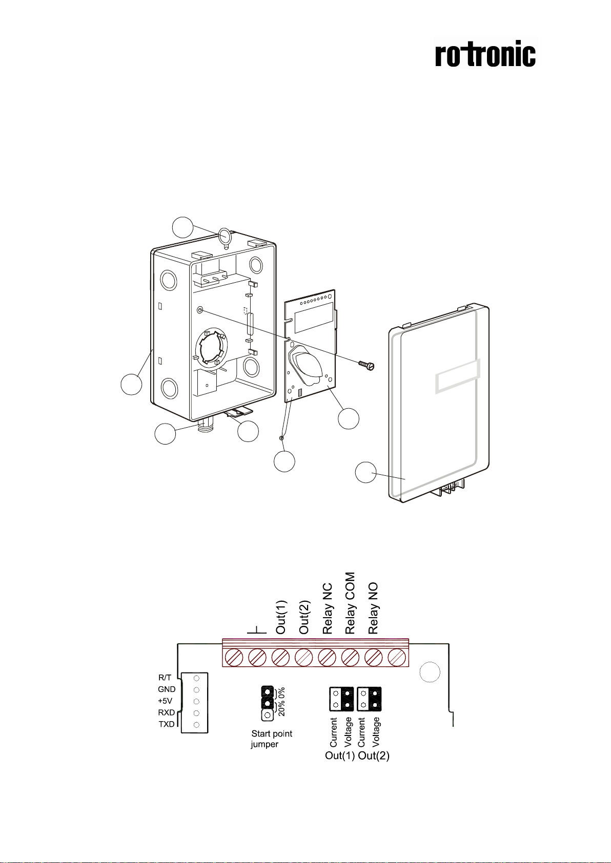
Installation manual
CF8-W-Disp-GH
CO2 transmitter with relay for use in
greenhouses
1 Back plate 5 Snap-in lid
2 PCB (mounted in the box at delivery) 6 Lid locking screw (not shown)
3 PG7 Cable entry bushing 7 Temperature sensor
4 Attachment loop
Terminals and jumpers on CF8-W-Disp-GH. The darker positions are default settings
Page 2
Dokument
IMA 211
Rev 1 Page
2 (4)
Connection
Function
Electrical Data
Remarks
Power (+)
(-)
24 VAC/DC+ (+-20%),
2W without output load
Out(1)
Analogue
0-10 VDC or 0-20 mA,
According to positions o f
See note 2!
5
Normally
relay
Contact free relay
Triggered by register
8
Not used
~
~
Electrical con nections
The power supply has to be connected to and . is considered as
system ground. If the analogue output is connected to a controller the same ground
reference has to be used for the CF8-W-Disp-GH unit and for the control system!
Unless different transformers are used, special precautions need to be taken.
PLEASE NOTE! The CF8-W-Disp-GH
signal ground is not galvanically
separated from the CF8-W-Disp-GH
power supply!
NOTE!
The same ground reference has
to be used for the CF8-W-Disp-GH
unit and for the control system!
Connect the power after mounting. The
analogue output should be connected before
measuring.
Terminal
Out(2)
6
7
Power ground
Output 1 (+)
Analogue
Output 2 (+)
closed relay
Relay COM
Normally open
3W
24 VAC/DC-
2-10 VDC or 4-20 mA,
0-10 VDC or 0-20 mA,
2-10 VDC or 4-20 mA
minimum load 1mA/5V
rated load 0,5A/125VA C ;
1A/24VDC
See note 1!
OUT1 and start point
jumpers.
See note 2!
According to positio ns o f
OUT2 and start point
jumpers.
OUT(3)
Table 1: Electrical connections
Page 3

Dokument
IMA 211
Rev 1 Page
3 (4)
Note 1: The ground terminal is used as negative power supply DC input or AC
phase ground G0 (halfwave rectifier).
Note 2:
CF8-W-Disp-GH can deliver a voltage or a current loop for OUT1 and OUT2.
To change between voltage and current output mode the hardware jumpers are
used. There is one jumper for OUT1 and one for OUT2, so that one output can be a
voltage output and the other a current output. Both, voltage output and current
output, can have start points 0 % (0-10 VDC or 0-20mA) or 20% (2-10 VDC or 420mA). The same start point is used for both outputs. See the function manual.
If for some reason the PCB must be removed it must be handed carefully
and protected from electrostatic discharge! Normally, removing the PCB is
not required.
Never feed more than one cable through each cable entry bushing.
The lid can be locked with the screw at the bottom of the sensor box.
Page 4

Dokument
IMA 211
Rev 1 Page
4 (4)
85 (3,35)
9,5 (0,37) 142 (5,59)
40 (1,57)
85 (3,35)
38 (1,5)
177 (7,0)
 Loading...