

Page 1
Dokument
IMA 213
Rev 1 Page
1 (3)
Installation manual
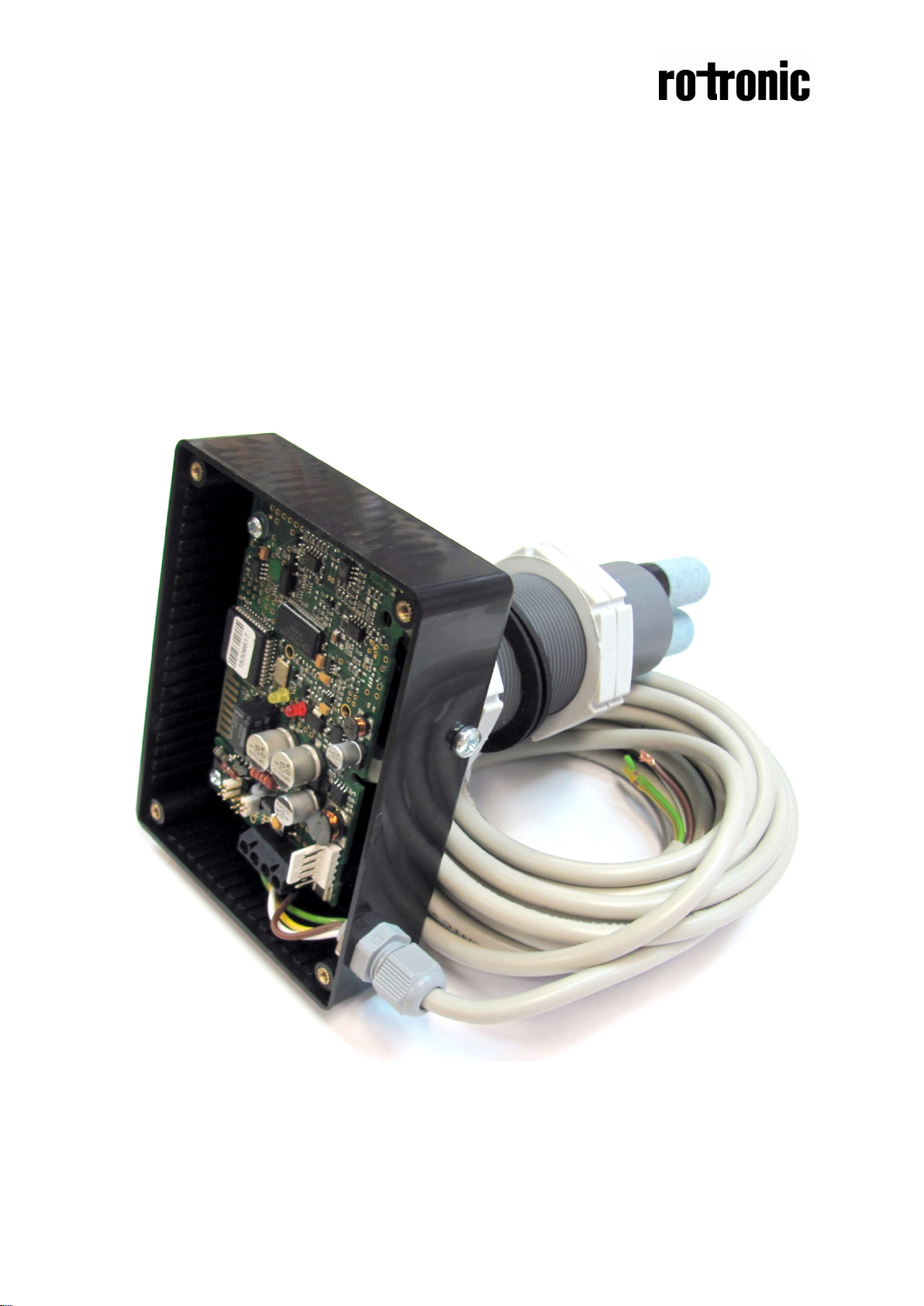
CF8-D/W-IN
General
The CF8-D/W-IN is used to measure the carbon dioxide concentration inside incubators.
Page 2
Dokument
IMA 213
Rev 1 Page
2 (3)
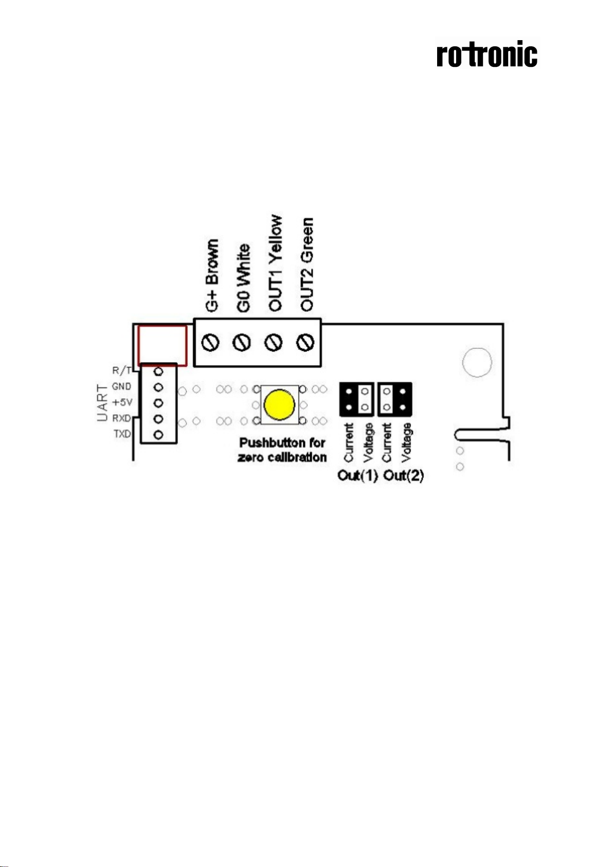
Figure 1. Terminals and jumpers on CF8-D/W-IN. The darker positions are default settings. The push
button is for forcing a manual zero point calibration if the sensor does not enter the automatic zero
calibration mode just by flowing zero gas.
Page 3

Dokument
IMA 213
Rev 1 Page
3 (3)
Terminal
G+
Power (+)
24 VAC/DC+ (+-20%), 3W
Brown
See note 1!
OUT 1
Analogue Output 1 (+)
4-20 mA or 2-10VDC
Yellow
Electrical con nections
The power supply has to be connected to G+ and G0. G0 is considered as s ystem ground. The sam e
ground reference has to be used for the CF8-D/W-IN unit and for any connected device! Unless
different transformers are used, special precautions need to be taken.
PLEASE NOTE!
The signal ground is not galvanically separated from
the CF8-D/W-IN power supply!
The same ground reference has to be used for the
CF8-D/W-IN unit and for any connected device!
If possible keep the sensor powered up after mounting
in order to avoid condensation. Connect the analogue
output before measuring.
When the installation is complete an automatic zero
point calibration (AZC) must be done. An automatic
zero point calibration (AZC) must be done at least once
a year according to warranty limitatio ns.
Connection
G0
OUT 2
Note 1: The ground terminal is us ed as negative power supply DC input or AC phas e ground G0
(halfwave rectifier). The signal ground is the same as power ground G0 (permitting a ”3-wire”
configuration). A single transformer may be used for the entire system.
Function
Power ground (-)
Analogue Output 2 (+)
Table I. Electrical terminal connections for CF8-D/W-IN
Electrical Data
24 VAC/DC
0-10mA or 0-5VDC
Remarks
2W without output load
White
According to positions of
OUT1 jumper. See note 2
and 3!
Green
According to positions of
OUT2 jumper. See note 2
and 3!
Note 2: CF8-D/W-IN can deliver both a voltage or a current loop for OUT1/OUT2. To change between
voltage and current output mode the hardware jumper s are used. There is one jumper for OUT1 and
one for OUT2, so that one output can be a voltage output and the other a current output.
Note 3: During start up the unit may deliver up to 10 VDC or 20 mA for up to half a second.
 Loading...