

Page 1
Dokument
UMA 148
Rev 1 Page
1 (6)
User manual
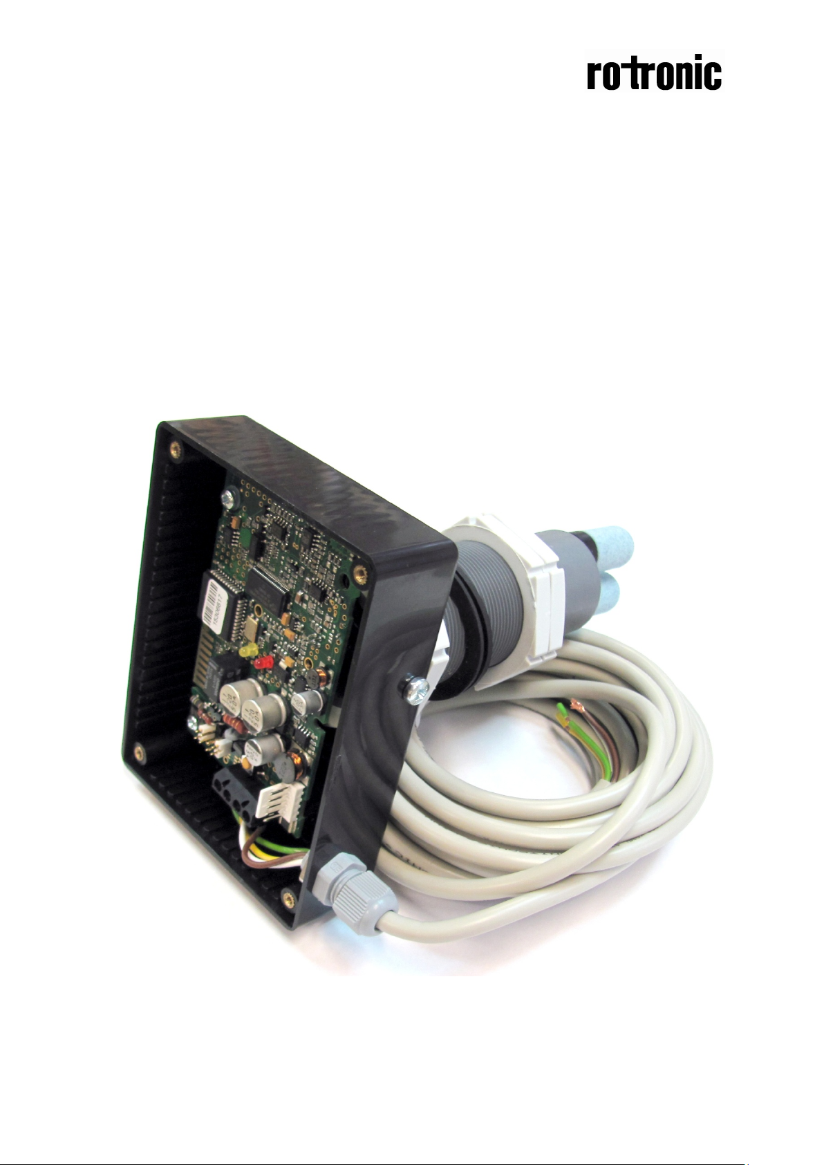
CF8-D/W-IN
General
The sensor CF8-D/W-IN is used to measure the carbon dioxide concentration inside incubators.
All functions can be modified from a PC with the communication cable.
Page 2
Dokument
UMA 148
Rev 1 Page
2 (6)
output range for OUT1. See note 1
output range for OUT2 See note 1.
Functional description
This part describes t he function of the configurati on of CF8-D/W-IN. Pleas e note that the two outputs
may completely or partly have other functions. These functions may be reprogrammed after the
installation. To be sure that every unit is correctly programmed, in accordance to the actual
application, a check by a PC and the standard UIP software (version 4.0 or higher) is necessary.
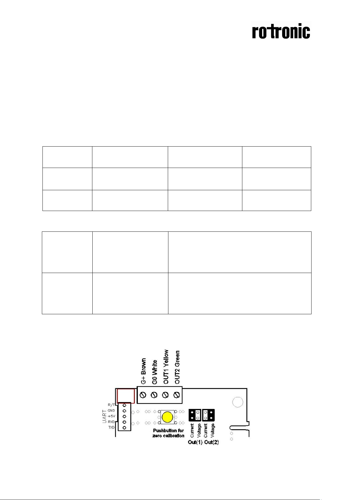
OUT1 and OUT2 are used for the measuring signal of carbon dioxide concentration.
OUT1 = measuring signal of carbon dioxide concentration
OUT2 = measuring signal of carbon dioxide concentration
Terminal
OUT1
Standard configuration
4-20mA
Standard settings *
0-3 % CO
2
Standard function
Measuring signal
OUT2
0-5VDC
0-2 % CO2
Measuring signal
Table I. Default configuration of CF8-D/W-IN
OUT1
OUT2
Current
Voltage
Current
Voltage
Connection in position “Current” provides 4-20mA
output range for OUT1. See note 1
Connection in position “Voltage” provides 2-10VDC
Connection in position “Current” provides 0-10mA
output range for OUT2. See note 1
Connection in position “Voltage” provides 0-5VDC
Table II. Configuration jumpers for
CF8-D/W-IN
Note 1: During start up the unit may deliver up to 10 VDC or 20 mA for up to half a second.
Page 3
Dokument
UMA 148
Rev 1 Page
3 (6)
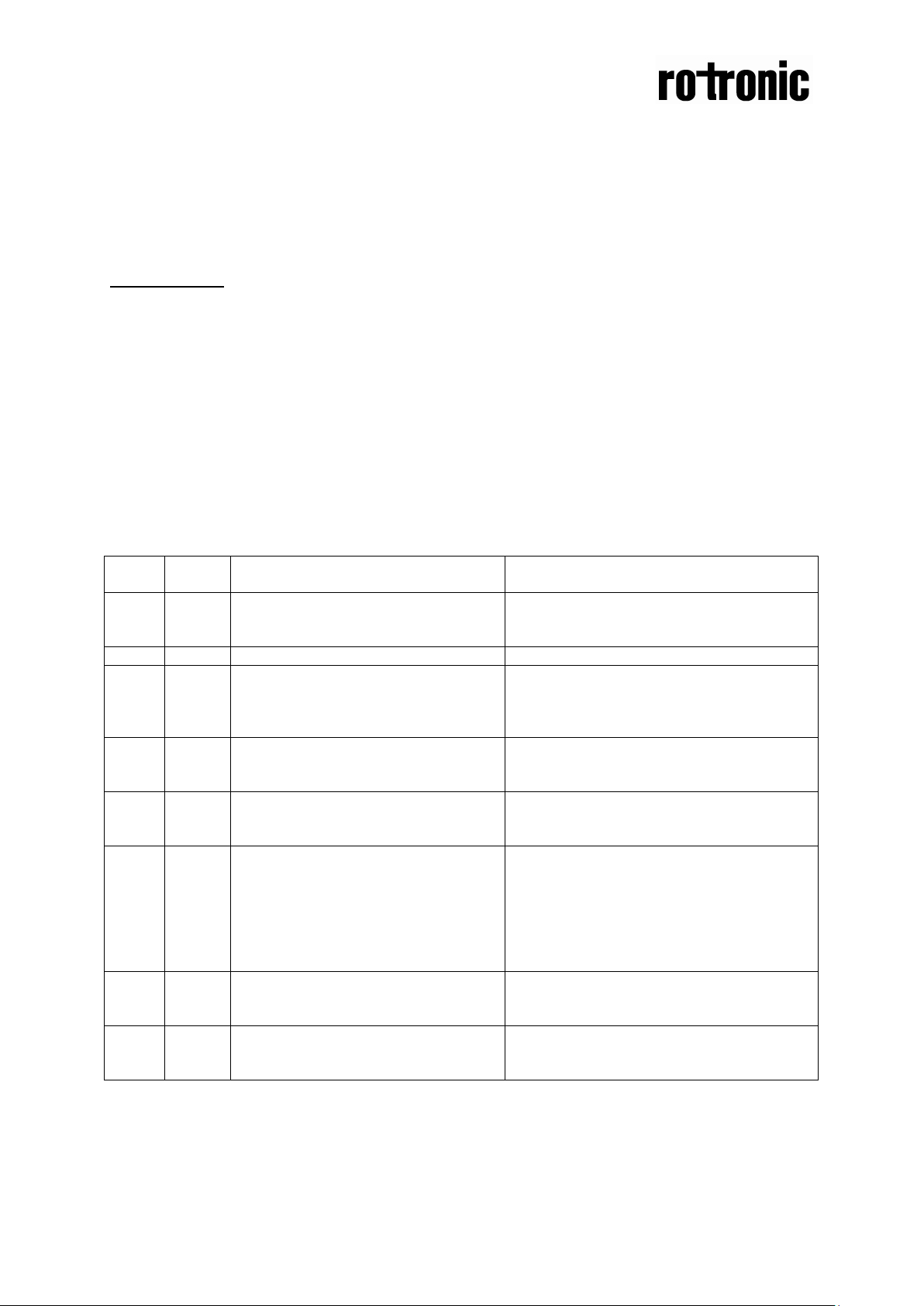
Bit #
Error
code
Error description
Suggested action
0
N/A
Fatal Error
Push buttons are not operating.
Try to restart sensor by power OFF/ON.
1
2
Reserved
2
4
Algorithm Error.
Try to restart sensor by power OFF/ON.
Contact local distributor
3
8
Output Error
calculation and generation.
Check connections and loads of outputs.
software version 4.0 and higher.
4
16
Self Diagnostic Error.
calibration or sensor replacement.
Check detailed self diagnostic status with
Contact local distributor
5
32
Out Of Range Error
error disappearance.
Try sensor in fresh air.
6
64
Memory Error
operations.
Check detailed settings and configuration
7
128
Warm Up state
failure. Resets after restart sequence.
If it doesn’t disappear in half a minute,
Functional test of CF8-D/W-IN
The unit has two LED’s -one yellow and one red. These LED’s indicate the status of the controller.
Yellow LED - ”Call for maintenance” is lit, if an error flag is set or the measurement is out of range.
The yellow LED flashes in series during Automatic Zero Point Calibration.
Red LED - ”Relay active” is lit for eight minutes when a zero point calibration has been executed.
PLEASE NOTE!
The sensor accuracy is defined at continuous operation.
Self diagnostics
The system contains complete self diagnostic procedures. A full system test is executed automatically
every time the power is turned on. For CF8-D/W-IN the internal voltage regulators and outputs are
checked. In addition, constantly during operation, the sensor probes are checked against failure by
checking the valid dynamic measurement ranges. These different system checks return error bytes to
the system RAM. If any error is detected, the yellow LED will be li t until the error has vanished and the
error flag is reset. “Warm up” and “Out of Range” are the only bits that are reset automatically after
return to normal state. All other error bits have to be reset manually after return to normal state by
power off and restart.
Descriptions of the different codes are listed below.
Yellow LED continuously flashes.
Indicate wrong EEPROM
configuration.
Detected errors during output signals
May indicate the need of zero
Accompanies most of other errors.
Can also indicate overload or failures
of sensors and inputs.
Resets automatically after source of
Non fatal error during memory
Is always set after power up or power
Contact local distributor
Check detailed settings and configuration
with UIP software version 4.0 and higher.
Check detailed status of outputs with UIP
UIP software version 4.0 and higher.
Check detailed status of measurements
with UIP software version 4.0 and higher.
See Note 1!
with UIP software version 4.0 and higher.
check power stability.
Note 1. Any probe is out of range. Occurs, for instance, during over exposure of CO2 sensor, in which
case the error code will automatically reset when the measurement values return to normal. Could
also indicate the need of zero point calibrat ion.
Remark: If several errors are detected at the same time the different error code numbers will be
added together into one single error code!
Page 4

Dokument
UMA 148
Rev 1 Page
4 (6)
Automatic Zero Point Calibration
The CF8-D/W-IN sensors have a function for easy automatic zero point calibration. The calibration
should be done after installation and at least once every year. The calibration can be done on site. It is
only necessary to connect the zero gas without any further action required from the operator, but to
check the verification signal offered from the system.
1. Unscrew one of the filters from the sensor housing and replace it with a hose nippl e.
2. Connect the zero gas to the nipple. The sensor automatically enters phase 1 of the calibration
procedure when the CO
during calibration.
3. When the calibration starts the yellow LED starts to flash. The sensor continues the procedure
until the readings of the sensor are stable enough and are below the limit of Automatic Zero Point
Calibration. If the conditions are not good enough for calibration within eight minutes the sensor
returns to normal measuring operation without calibration.
4. When the calibration is successfully executed the yellow LED flashes four times, pauses and
flashes another four times for an eight minutes acknowledgement period, phase 2. During the
acknowledgement period the relay is closed and the red LED is lit.
5. Remove the zero gas during the acknowledgement period. The sensor returns to norm al
measuring mode as soon as the calibration is ready. The yellow LED continues flashing, the red
LED is lit and the relay is closed independent of gas removal.
The zero gas can be generated by passing air through the chemical absorber in the service bag
F0005 or by using nitrogen in a gas bottle. Not more than three minutes shall pass before the yellow
LED starts to flash. If the yellow LED does not start to flash the zero gas is not good enough or the
sensor is not stable enough. Wait ten minutes before another attempt to calibrate the sensor.
If the sensor does not enter phase 1 even if the conditions are good push the push button on the PCB
until the red LED is lit to force a manual zero point calibration. Push the push button for at least ten
seconds.
concentration drops sharply. See figure 2. Do not remove the zero gas
2
Page 5

Dokument
UMA 148
Rev 1 Page
5 (6)
is reached
800
700
Normal
measurement
Phase 1 Check
calibration conditions
Phase 2 Acknowledgement period
600
Zero gas
Yellow LED
500
flashes
Automatic Zero
Point Calibration
400
ppm CO2
300
200
100
Calibration is executed The yellow
LED flashes four times The red LED
is lit The relay is closed
0
0 50 100 150 200 250 300 350
Time seconds
Figure 2. An example of Automatic Zero Point Cal ibra t ion
The Automatic Zero Point Calibration should be executed after installation and at least once a
year.
Trouble shooting
The yellow LED does not start to flash. The sensor does not enter calibration mode within three
minutes.
1. The absorber of the zero gas bag is not fresh. Remove the old absorber and refill the bottle with
fresh. The absorber is corrosive! Be careful and wear eye protection goggles.
2. The flow of the zero gas is too small or air is leaking into the sensor. The gas flow must be about
0,5 l/min.
3. Push the push button on the PCB for ten seconds (until the red LED is lit) to force manual zero
point calibration. Please check the gas before pushing the push button since the calibration is
executed even if the gas is not good enough.
Contact the dealer if the sensor still does not enter the calibration mode.
Page 6

Dokument
UMA 148
Rev 1 Page
6 (6)
This product is in accordance with the
EMC Directive 89/336/EEC and the
Low Voltage Directive 73/23/E EC inclu di ng
amendments by the CE-marking Directive
93/68/EEC
The product fulfils the following demands:
EN50081-1, EN55011(B)
EN50082-2, EN61000-4-2,-3,-4,-5, Level3
 Loading...