

Page 1
Dokument
Rev Page
1 (7)
User manual
CF5
CO2 / temperature transmitter
General
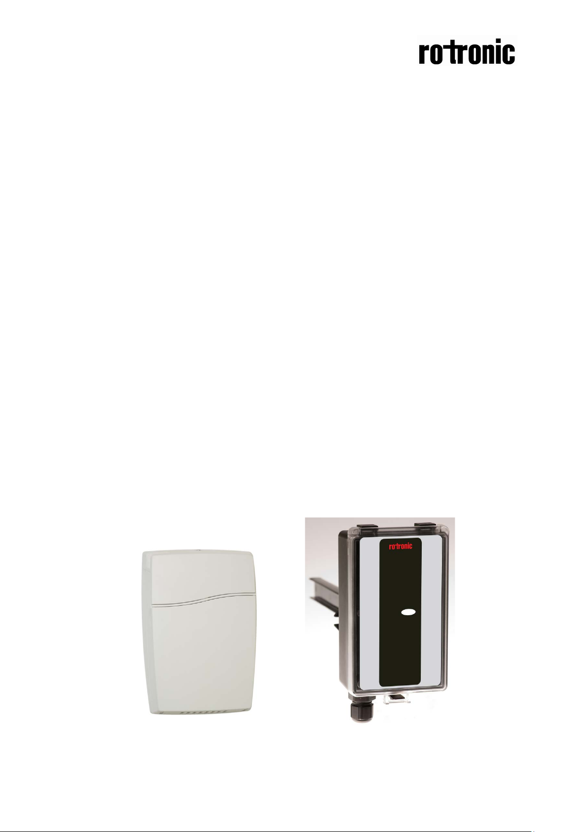
The IAQ-sensor product CF5 is used to measure indoor air carbon dioxide
concentration and temperature in rooms. The CF5 is available both with and without
display, (LCD). Both are available for wall mounting as well as for duct mounting.
The unit is designed for connecting to Direct Digital Control (DDC). The linear output
functions are pre-programmed as CO2 and temperature transmitters with jumper
selected outputs 0-10 V / 2-10 V / 0-20 mA / 4-20 mA. The measuring ranges can be
modified from a PC (Windows) and use of the software UIP (version 4.3 or higher)
together with the RS232 communication cable.
Figure 1 CF5 for wall mounting and duct mounting
Page 2
Dokument
Rev Page
2 (7)
Output
sensor
this sensor
Configuration
Output Range
Formula for calculation
0-50 oC
Temperature value in oC = Volt/10*50
0-50 oC
Temperature value in oC = (Volt –2)/8*50
0-50 oC
Temperature value in oC = (mA-4)*50/16
a-b c–d
Value = (reading-a)/(b-a)*(d-c)+c
a = lowest value of the configuration
d = highest value of the range
Terminal
Out(1)
Out(2)
Default
0-10VDC
0-10VDC
Table I. Default output configurations for CF5
Default Output
Range
0-2000 ppm CO2
0-50 oC
Outputs of this
Formulas for calculati on of out put values
0-10 VDC
2-10 VDC
0-2000 ppm CO
0-2000 ppm CO
CO2 value = Volt/10*2000
2
CO2 value = (Volt –2)/8*2000
2
Output Range of
4-20 mA
0-2000 ppm CO
CO2 value = (mA-4)*2000/16
2
b = highest value of the configuration
c = lowest value of the range
Table II. Calculation of CO2 value and temperature value for CF5
Output Configurations
The sensors/controllers are supplied from the factory (unless otherwise ordered) with
0...10VDC linear outputs for Out(1) and Out(2) (see Table I). If other options are
needed for the application, the output jumpers have to be configured before the unit
is powered up. Each jumper selection is independent from the others, except for the
“Start point selection” jumper, which affects both Out(1) and Out(2) linear outputs.
Alternative measuring ranges of the outputs can be selected with the software UIP
(version 4.3 or later).
Page 3
Dokument
Rev Page
3 (7)
0%
Jumper top position provides 0Vdc or 0mA start point for Out(1), Out(2)
NOTE! The start point jumper is missing on some models!
Current
Connection in position “Current” provides 0/4-20mA output range for Out(1).
configured in voltage outputs mode.
Current
Connection in position “Current” provides 0/4-20mA output range for Out(2).
configured in voltage outputs mode.
Jumper Position Function
Start
point
selection
jumper
Out(1)
Out(2)
20%
Voltage
Voltage
(0-20mA or 0-10V).
Jumper bottom position provides 2Vdc or 4mA start point for Out(1), Out(2) (4-
20mA or 2-10V).
Current output is not recommended for temperature measurements
Connection in position “Voltage” provides 0/2-10VDC output range for Out(1).
Please note! Temperature measurements accuracy is valid only for units
Current output is not recommended for temperature measurements
Connection in position “Voltage” provides 0/2-10VDC output range for Out(2).
Please note! Temperature measurements accuracy is valid only for units
Table II. Configuration jumpers for CF5
Self-diagnostics
The system contains complete self-diagnostic procedures. A full system test is
executed automatically every time the power is turned on. In addition, constantly
during operation, the sensor probes are checked against failure by checking the valid
dynamic measurement ranges. All EEPROM updates, initiated by the sensor itself, as
well as by external connections, are checked by subsequent memory read back and
data comparisons. These different system checks return error bytes to the system
RAM. The error codes are available by connecting a PC with a special RS232 cable
connected to the UART port slide connector. The error codes are shown in the
software UIP (version 4.3 or later). Warm up and Out of Range are the only bits that
are reset automatically after return to normal state. All other error bits have to be
reset manually after return to normal by power off/on.
The yellow LED flashes if an error has been detected. If a fatal error has been
detected the yellow LED is lit.
Page 4

Dokument
Rev Page
4 (7)
Bit #
Error
code
Error description
Suggested action
0
N/A
Fatal Error
Try to restart sensor by power
OFF/ON. Contact local distributor
1
2
Reserved
2
4
Algorithm Error.
Try to restart sensor by power
3
8
Output Error
Check connections and loads of
4
16
Self-Diagnostic Error.
Check detailed self-diagnostic status
5
32
Out Of Range Error
Try sensor in fr esh ai r .
6
64
Memory Error
Check detailed settings and
7
128
Warm Up state
If it doesn’t disappear in half a
Error code and action plan
Indicate wrong EEPROM
configuration.
Detected errors during output
signals calculation and
generation.
May indicate the need of zero
calibration or sensor
replacement.
Accompanies most of other
errors. Can also indicate
overload or failures of sens or s
and inputs.
Resets automatically after
source of error disappearance.
OFF/ON.
Check detailed settings and
configuration with UIP software
version 4.3 and higher.
Contact local distributor.
outputs.
Check detailed status of outputs
with UIP software version 4.3 and
higher.
with UIP software version 4.3 and
higher.
Contact local distributor
Check connections of temperature
and relative humidity probe.
Check detailed status of
measurements with UIP software
version 4.3 and higher.
See Note 1!
Non-fatal error during memory
operations.
Is always set after power up or
power failure. Resets after
restart sequence.
Note 1. Any probe is out of range. Occurs, for instance, during over exposure of CO2 sensor, in which
case the error code will automatically reset when the measurement values return to normal. C ould
also indicate the nee d of ze ro po int c al ibrat io n. If the CO2 readings are nor mal , a n d s ti ll the er ror c o de
remains, the temperature sensor can be defect or the connections to it are broken.
configuration with UIP software
version 4.3 and higher.
minute, check power stability.
Page 5

Dokument
Rev Page
5 (7)
Gas inlet
Gas inlet
Remark: If several errors are detected at the same time the different error code numbers will be
added together into one single error code!
PLEASE NOTE! The sensor accuracy is defined at continuous operation (at
least 3 weeks after installatio n )
Maintenance
The CF5 is basically maintenance free. An internal self-adjusting calibration function
takes care of normal long term drift associated to the CO2 sensor. To secure the
highest accuracy, a time interval of five years is recommended between CO2
calibrations, unless some special situations have occurred. A zero calibration can be
performed by use of pure nitrogen or air that has passed through a chemical
absorber and a PC together with the UIP software version 4.3 (or higher). The
Service bag can be used to produce carbon dioxide free air. The software can be
free downloaded from www.rotronic.com. The RS23 2-cable and the zero calibration
bag can be ordered from Rotronic. The cable is to be connected to the UART port
slide connector (see Fig. 5). For change of control parameters and re-calibration
(CO2 and temperature) this PC tool has to be used. The check can be done on site
without interfering with the ventilation system.
This is for sensors with measuring ranges between 0-3000 ppm and 0-4%:
When a zero calibration shall be executed a plastic tube with 2,2 mm outer diameter
and 0,8 mm inner diameter shall be inserted in marked holes of the sensor. Plastic
tubing is connected to the tube. The gas flow should be between 0,3 and 1,0 l/min.
Figure 2 Part of the PCB with holes for gas inlets marked.
Duct mounting
If for some reason the printed circuit board (PCB) needs to be removed, special
precaution must be taken in order not to damage the temperature probe in the
sampling tube. When putting the PCB back in the protective housing, the probe must
be gently positioned in the sampling tube.
Page 6

Dokument
Rev Page
6 (7)
+
~
Figure 3 The CF5 printed circuit board with CO2 sensors for measuring ranges 0-3000p pm, 0-10% and
0-25%. PCBs with long temperature sensors are for duct mounting. The start point jumper is not
mounted on some models.
Figure 4 The CF5 for duct mounting. The temperature probe is the black body in the sampling tube.
Figure 5 Terminals and jumpers on CF5. The darker positions are default settings. The start point
jumper is not mounted on some models.
Page 7

Dokument
Rev Page
7 (7)
This product is in accordance with the
EMC 2004/108/EC, 92/31/EEG
including amendments by the CE-marking Directive 93/68/EEC
The product fulfils the following demands:
EN 61000-4-2 level 2,
EN 61000-4-3 level 2,
EN 61000-4-4 level 4,
EN 61000-4-6,
EN 61000-4-8 level 4,
EN 55022 class B
 Loading...