

Page 1
Dokument
IMA 212
Rev 1 Page
1 (4)
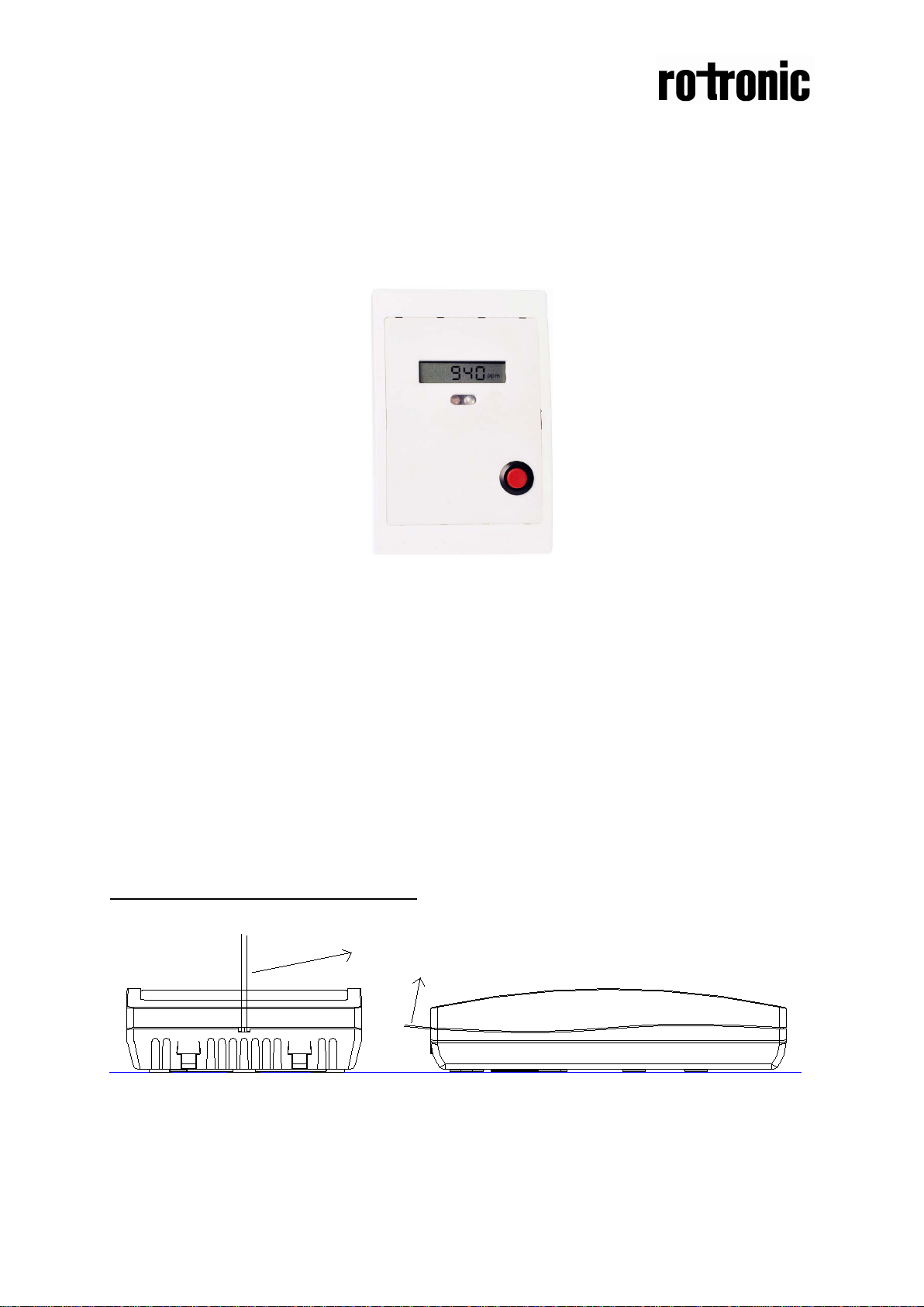
Front
Wall
Insert screw driver
Push upwards to open
Front
Wall
Installation manual
CF3-W-US-Disp-FLI
CO2 transmitter and alarm
CF3-W-US-Disp-FLI
General
The alarm product CF3-W-US-Disp-FLI is designed to measure carbon dioxide (CO2)
in rooms. Option - Disp displays the measured CO2 value in ppm (parts-per-million)
on the LCD. LEDs are lit to give an overview of the CO2 value.
An acoustic alarm sounds when the CO2 value is above 1400ppm. The acoustic
alarm can be silenced with a push button on the side of the instrument.
The units are designed for connecting to Direct Digital Control (DDC) with 0-10V
signal inputs.
To open the wall mounted housing
Figure 1. Closed housing seen from the top and the side. The housing is opened by inserting
a screw driver and pushing to the front side of the housing. The locking hooks will then be
released.
Page 2
Dokument
IMA 212
Rev 1 Page
2 (4)
128,4(5,06)
85(3,34)
32,7(1,29)
30(1,18)30(1,18)
30(1,18)
30(1,18)
52,5(2,07)
30(1,18)
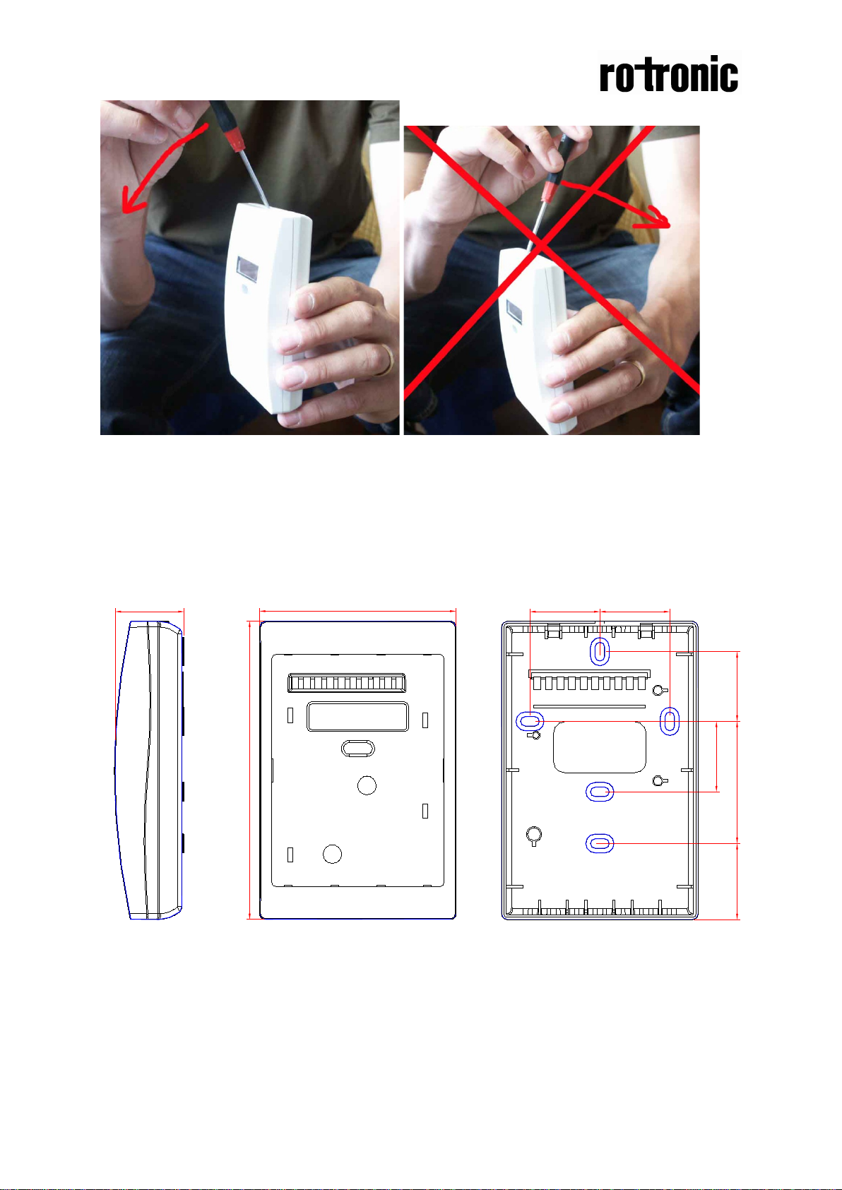
Figure 2. Closed housing seen from the side. Figure 3. Closed housing seen from the side.
The housing is opened by inserting a screw Never push to the right. The locking hooks
driver and pushing left (to the front side). may break and the housing is damaged
The locking hooks will then be released.
Dimensions
Figure 3. The dimensions of the sensor in mm and (inches)
Page 3

Dokument
IMA 212
Rev 1 Page
3 (4)
Terminal
Function
Electrical data
Remarks
+~
Power (+)
Power ground (-)
24 VAC/DC+ (+-20%),
24 VAC/DC-
System voltage reference
OUT1
Analogue output
acoustic alarm
0-10 VDC
0-2000 ppm CO2
for 30 minutes.
LED Colour
Electrical data
Remarks
Green
0VDC
10VDC
Lit between 0-800 pp m CO2
Yellow
0VDC
10VDC
Lit between 800-14 00 ppm CO2
Red
0VDC
10VDC
Lit above 1400 ppm CO2. Buzzer sounds.
Electrical connections
The power supply has to be connected to +~ and . is considered as system
ground. The same ground reference has to be used for the CF3-W-US-Disp-FLI unit
and for the DDC/signal receiver.
PLEASE NOTE! The same ground reference has to be
used for the CF3-W-US-Disp-FLI unit and for the control
system!
OUT2
1 (+)
Silences the
Table I. Connections of the main terminal of CF3-W-US-Disp-FLI
Table II. The LEDs
2W
A push on the push button
silences the acoustic alarm
Self-diagnostics
The system contains complete self-diagnostic procedures that are executed
automatically when the sensor is in operation. Sensors with display show a wrench if
an error is found. The wrench is shown during the first seconds after power up and if
the measuring range is exceeded.
Maintenance
The CF3-W-US-Disp-FLI is basically maintenance free in normal environments
thanks to the built-in self-correcting ABC algorithm.
PLEASE NOTE! The sensor accuracy is defined at continuous operation (at
least 3 weeks after installatio n )
Electronic products should be disposed of via a suitable recycling centre.
Page 4

Dokument
IMA 212
Rev 1 Page
4 (4)
Figure 3. The
CF3-W-US-Disp-FLI PCB
Figure 4. The upper part of the
CF3-W-US-Disp-FLI PCB seen from the back with the
jumper in voltage (default) and current position
 Loading...