

Page 1
Dokument
IMA 203
Rev 1 Page
1 (4)
Front
Wall
Insert screw driver
Push upwards to open
Front
Wall
Installation manual
CF3-W-US, CF3-W-US-Disp
CO2 transmitter
CF3-W-US CF3-W-US-Disp
General
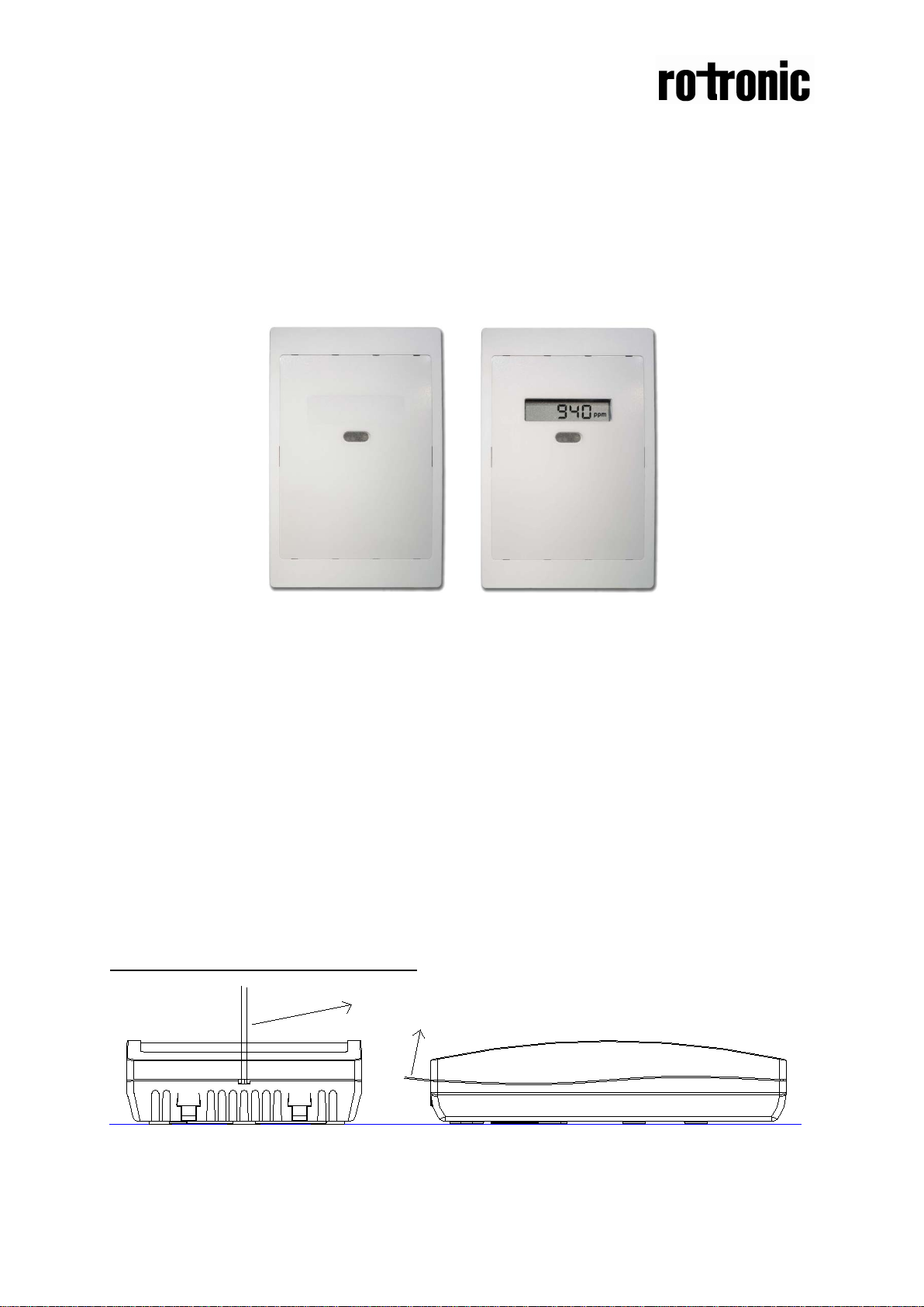
The IAQ-sensor product CF3-W-US (sensor for wall mounting) is designed to
measure carbon dioxide (CO2) in rooms. Option - Disp displays the measured CO2
value in ppm (parts-per-million) on the LCD.
The units are designed for connecting to Direct Digital Control (DDC). The two
parallel signal outputs OUT1 (0-10 V) and OUT2 (2-10 V or 4-20 mA) give linear
signals corresponding to the measuring range.
The OUT2 output also indicates the status by setting the output voltage to 1 V or
current to 2 mA when the sensor self-diagnostics detects any error.
To open the wall mounted housing
Figure 1 Closed housing seen from the top and the side. The housing is opened by inserting a screw
driver and pushing to the front side of the housing. The locking hooks will then be released.
Page 2
Dokument
IMA 203
Rev 1 Page
2 (4)
128,4(5,06)
85(3,34)
32,7(1,29)
30(1,18)30(1,18)
30(1,18)
30(1,18)
52,5(2,07)
30(1,18)
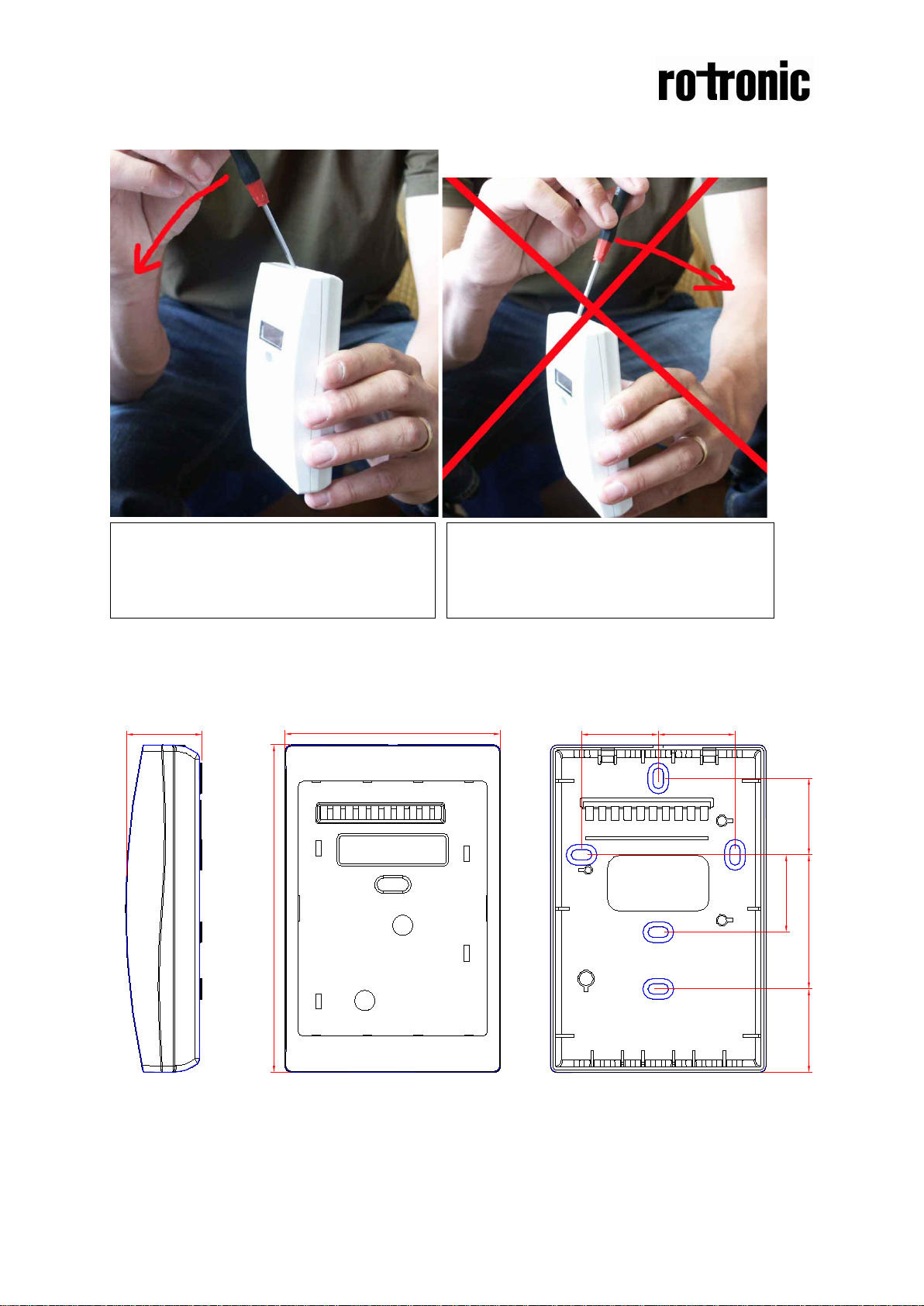
Figure 3 Closed housing seen from the side
Figure 2 Closed housing seen from the side
The housing is opened by inserting a screw
driver and pushing left (to the front side).
The locking hooks will then be released.
Never push to the right. The locking hooks
may break and the housing is damaged.
Dimensions
Figure 4 The dimensions of the sensor in mm and (inches)
Page 3

Dokument
IMA 203
Rev 1 Page
3 (4)
Terminal
Function
Electrical data
Standard settings
Settings of
Power (+)
24 VAC/DC+
OUT(1)
Analogue
0-10 VDC
0-2000 ppm CO2
READY
~
~
Electrical connections
The power supply has to be connected to and . is considered as system
ground. The same ground reference has to be used for the CF3-W-US unit and for the
DDC/signal receiver.
PLEASE NOTE! The same ground reference has to be
used for the
CF3-W-US unit and for the control s ystem !
this sensor
OUT(2)
output 1 (+)
output 2 (+)
(+-20%), 2W
Power
24 VAC/DC-
ground (-)
Analogue
2,0…10,0 VDC or
4,0 … 20,0 mA
0,9…1,6 VDC or
1.5 to 2,5 mA
0 VDC or 0mA
Table I. Connections of the main terminal of CF3-W-US
System voltage
reference
0-2000 ppm CO
Status = ERROR
Status = NOT
2
Figure 5 The CF3-W-US PCB seen from the front and the back. The OUT2 jumper is in the default
position (voltage)
Page 4

Dokument
IMA 203
Rev 1 Page
4 (4)
Configuration jumper for OUT2 output
The output OUT2 can be used as a voltage or current output. The output is
configured by the jumper on top of the PCB. The configuration of the output can be
changed by moving the jumper to the desired position. The output has to be
reconfigured before the unit is powered up.
Figure 6 The upper part of the CF3-W-US PCB seen from the back with the jumper in voltage (default)
and current position
Self-diagnostics
The system contains complete self-diagnostic procedures that are executed
automatically when the sensor is in operation. Sensors with display show a wrench if
an error is found. The wrench is shown during the first seconds after power up and if
the measuring range 2000 ppm is exceeded. The output OUT2 indicates the same
information by setting the output to 1 V or 2 mA.
PLEASE NOTE!
The sensor accuracy is defined at continuous operation (at least 3 weeks after
installation)
 Loading...