

Page 1
Dokument
IMA 201
Rev 2 Page
1 (4)
Press here to open.
Installation manual
CF3-W-EU, CF3-W-EU-Disp
CO2 transmitter
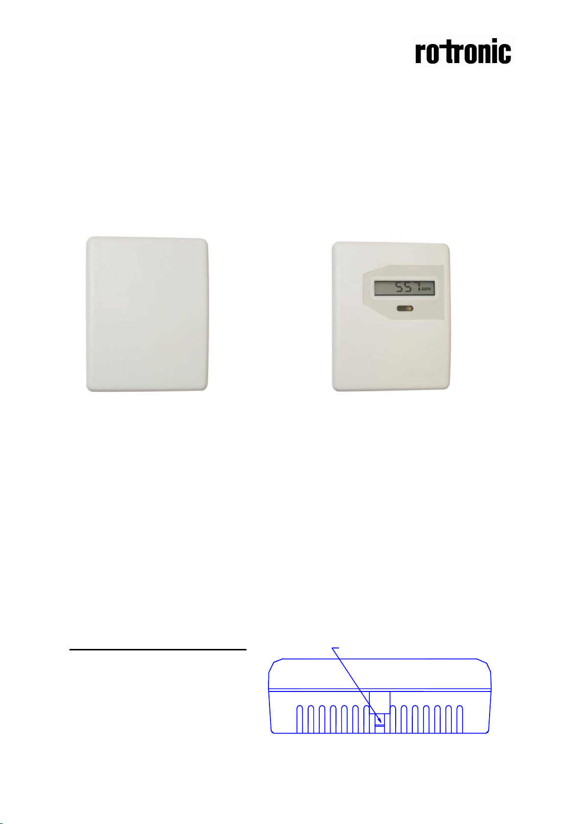
CF3-W-EU CF3-W-EU - Disp
General
The IAQ-sensor product CF3-W-EU (sensor for wall mounting) is designed to
measure carbon dioxide (CO2) in rooms. Option - TR is prepared for temperature
measurements by the resistive temperature probe mounted by the user. The
temperature probe is potential free (floating). Option - Disp displays the measured
CO2 value in ppm (parts-per-million) on the LCD.
The units are designed for connecting to Direct Digital Control (DDC) with 0-10V or
2-10V signal inputs. The two parallel signal outputs OUT1 (0-10V) and OUT2 (2-10V
or 4-20 mA) give linear signal voltages or currents corresponding to the measuring
range.
The output OUT2 also indicates the status by setting the output voltage to 1V or the
output current to 2 mA when the sensor self-diagnostics detects any error.
To open the wall mounted housing
Figure 1. Closed housing seen from
above. The housing is opened by
pressing a screw driver on the locking
hook. The locking hook is then
released.
Page 2
Dokument
IMA 201
Rev 2 Page
2 (4)
Terminal
Function
Electrical data
Remarks
Remarks
this sensor
Power (+)
ground (-)
24 VAC/DC+
reference
Out(1)
Analogue
0-10 VDC
0 VDC or 0mA
0-2000 ppm CO2
Status = NOT READY
~
~
Option display
+
~
Electrical connections
The power supply has to be connected to and . is considered as system
ground. The same ground reference has to be used for the CF3-W-EU unit and for the
DDC/signal receiver.
PLEASE NOTE!
The same ground refere nce has to be used for the CF3-W-
EU
unit and for the control s ystem!
Out(2)
Power
output 1 (+)
Analogue
output 2 (+)
Table I. Connections of the main terminal of CF3-W-EU
(+-20%), 2W
24 VAC/DC-
2,0-10,0 VDC or
4,0-20,0 mA
0,9-1,6 VDC or
1.5-2,5 mA
Standard settings
System voltage
0-2000 ppm CO
2
Status = ERROR
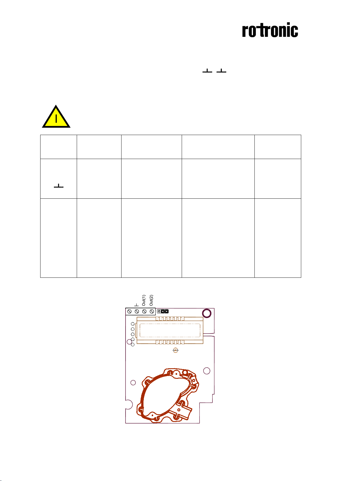
Settings of
Figure 2. PCB with jumper to configure OUT2 for current output 4-20mA or voltage output 210VDC
Page 3
Dokument
IMA 201
Rev 2 Page
3 (4)
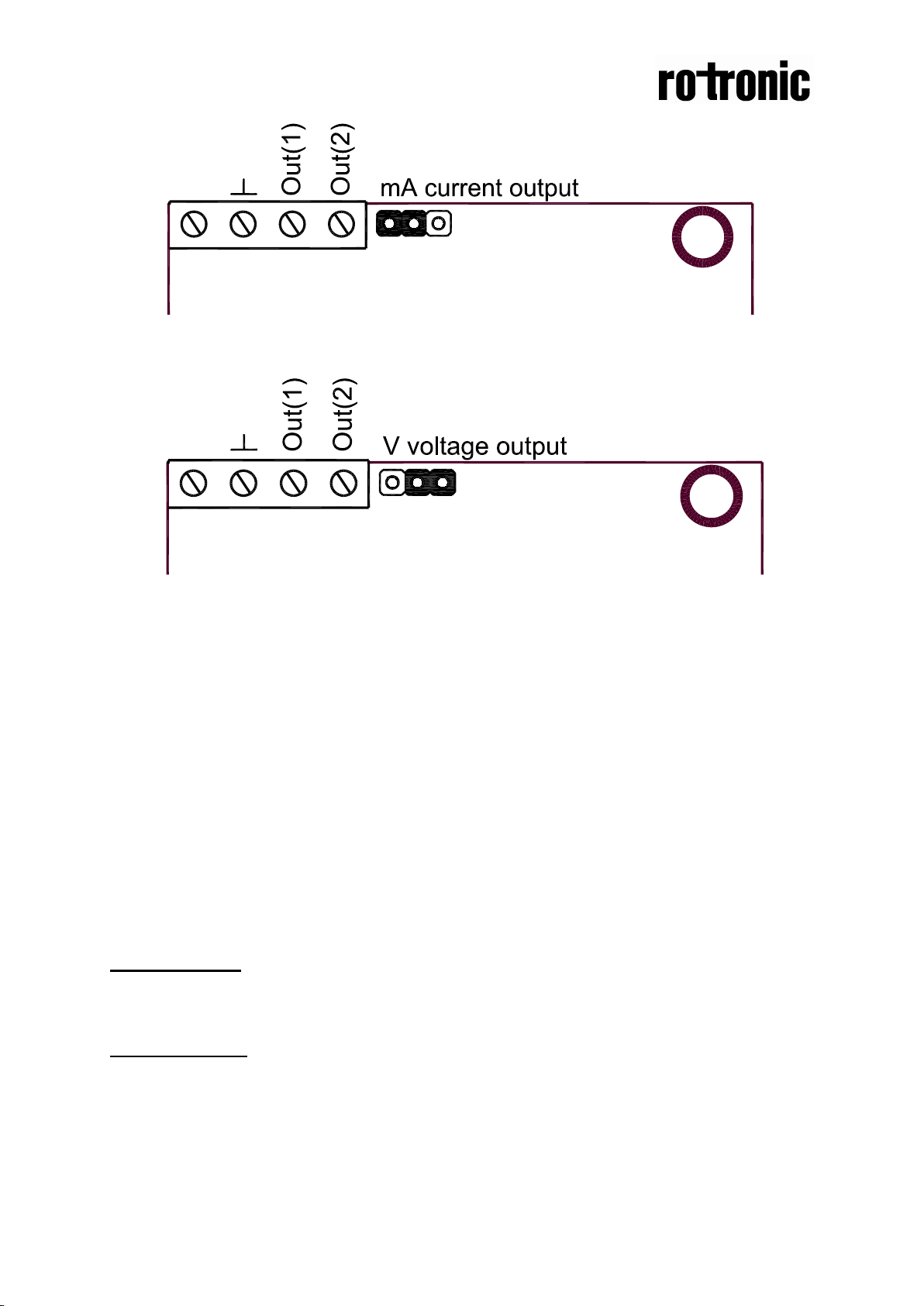
+
~
+
~
Figure 3. Enlarged picture of the PCB with the jumper set to current output (left position)
Figure 4. Enlarged picture of the PCB with the jumper set to voltage output (right position)
Self-diagnostics
The system contains a complete self-diagnostic procedure that is executed
automatically when the sensor is in operation. The yellow LED is lit if an error is
found. Sensors with display show a wrench if an error is found. The wrench is shown
and the yellow LED is lit during the first seconds after power up and if the measuring
range exceeded. They are automatically turned off when the sensor returns to normal
operation. The output OUT2 indicates the same information by setting the output
voltage to 1V or 2 mA.
Maintenance
The CF3-W-EU is basically maintenance free in normal environments thanks to the
built-in self-correcting ABC algorithm.
PLEASE NOTE!
The sensor accuracy is defined at continuous operation (at least 3 weeks after
installation)
PLEASE NOTE! Electronic products should be disposed of via a suitable
recycling centre.
Page 4

Dokument
IMA 201
Rev 2 Page
4 (4)
80(3,15)
28(1,10)
30(1,18)
60(2,36)
4(0,16)
4(0,16)
30(1,18)
100(3,94)
Dimensions
Figure 5. The dimensions of the sensor in mm and (inches)
Mounting of the sensor onto the wall
Please use screws with screw head diameter less than 7,5 mm (0,295 inches) and
screw head height less than 2,4 mm (0,094 inches).
 Loading...