

Page 1
Dokument
IMA 204
Rev 2 Page
1 (7)
Installation manual
CF3-D, CF3-D-Disp
Figure 1 The sensor
General
The IAQ-sensor product CF3-D (for mounting in ventilation duc ts) is designed to
measure carbon dioxide (CO2). Option - TR is prepared for temperature
measurements by the resistive temperature probe mounted by the user. Option -Disp
displays the measured CO2 value in ppm (parts-per-million) on the LCD.
The units are designed for connecting to Direct Digital Control (DDC) with 0-10V or
2-10V signal inputs. The two parallel signal outputs Out(1) (0-10V) and Out(2) (2-10V
or 4-20 mA) give linear signal voltages or currents corresponding to the measuring
range.
The output OUT(2) also indicates the status by setting the output voltage to 1V or the
output current to 2 mA when the sensor self-diagnostics detects any error.
Page 2
Dokument
IMA 204
Rev 2 Page
2 (7)
1
2
1
2
3
4
5
6
7
9
8
10
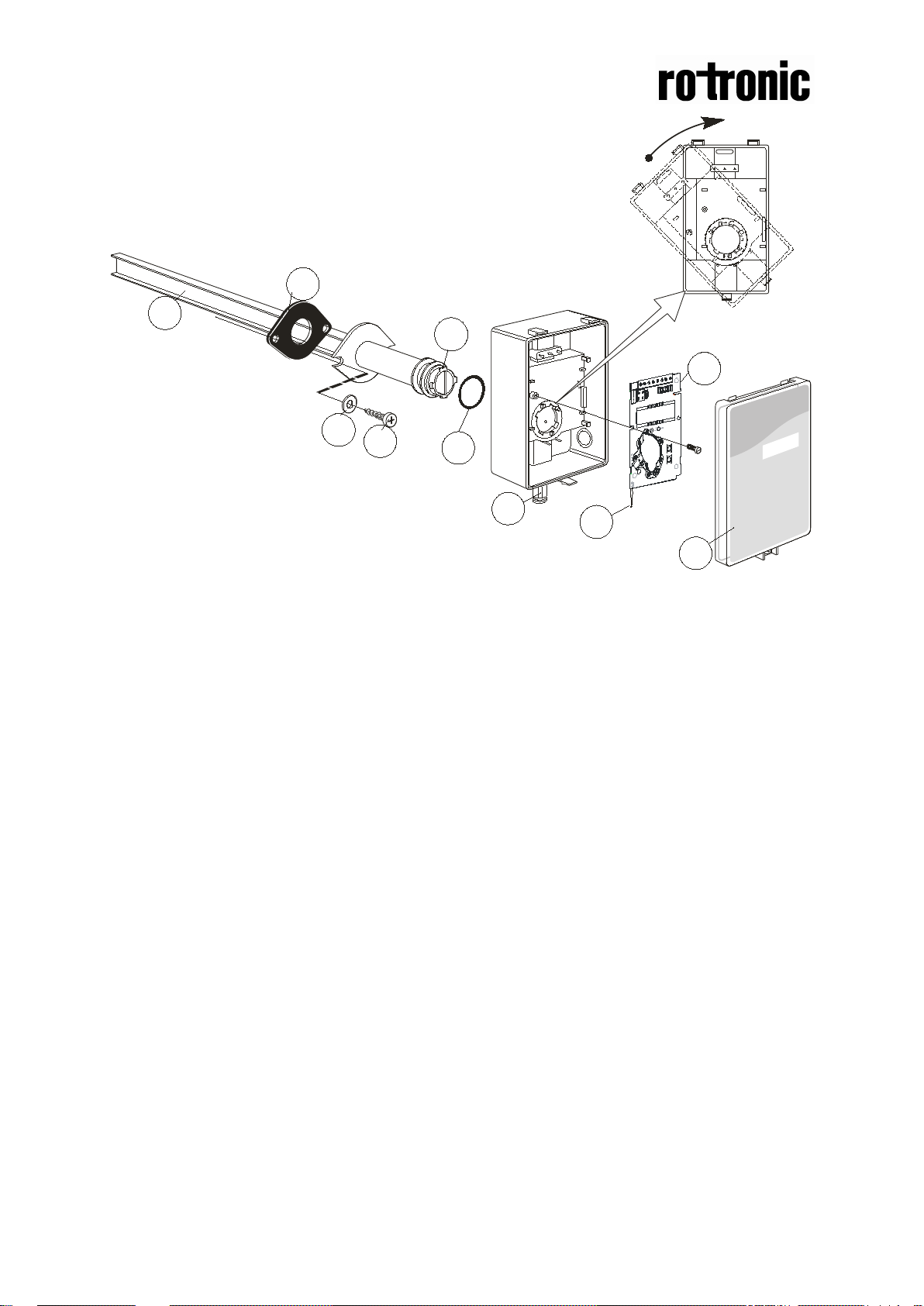
Figure 2 Parts of the CF3-D for duct mounting
1 Sampling probe 6 O-ring 29,2x3,53 (Factor y mount ed in box )
2 Sealing gasket 7 PCB (Factory supplied mounted in box)
3 Largest locking nob 8 Snap-in lid
4 2 washers 9 PG9 cable entry bushing
5 2 screws
Page 3
Dokument
IMA 204
Rev 2 Page
3 (7)
10
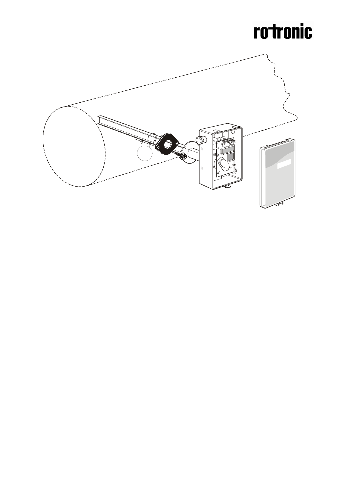
Mounting of CF3-D on to the duc t.
Figure 3 Mounting of the sensor to the ventilation duct
10 Hole with 25 mm diameter
11 Temperature sensor with 110 mm cable mounted in the sampling probe
Mounting Instruction
Since there might be a substantial pressure difference in duct mounting applications,
it is essential to avoid ambient air from suction into the duct mounting box. For
correct function it is indispensable that the sealing of the box cover, the cable entry
bushings, the cable feed through and the duct entrance are absolutely tight. The duct
entrance may need extra sealing paste in order to prevent leakage. The PCB must
be handed carefully and protected from electrostatic discharge.
1) Electrical cable ent ry: The box has a factory mounted cable entry bushing in
dimension PG9. Never feed more than one cable through each cable entry
bushing, or else gas might leak through!
2) Mounting the tube: Drill a hole (10) with 25 mm diameter (or 1 inch) for the
sampling probe and two holes with 4 mm diameter for the screws (5) into the air
duct and mount the tube (1) with the gasket (2). The sampling probe should be
mounted with the largest locking knob on top. The unit can be mounted with the
air coming from the left or right.
3) Attaching the sensor box is made to the sampling probe by a snap-in bayonet
fitting. Orient the box onto the sampling probe so that the box upside is on the
same side as the largest locking knob (3). When the probe is fitted into the
notches of the box, then turn the box clockwise until stop (see Figure 1). Position
1 indicates open where the box can be removed from the sampling probe. In
position 2 the box is locked to the probe.
Page 4

Dokument
IMA 204
Rev 2 Page
4 (7)
Terminal
Function
Electrical data
Remarks
Remarks
Power (+)
(-)
24 VAC/DC+ (+-
reference
Out(1)
Analogue
0-10 VDC
0-2000 ppm CO2
READY
~
~
Electrical connections
The power supply has to be connected to and . is considered as system
ground. The same ground reference has to be used for the CF3-D unit and for the
DDC/signal receiver.
PLEASE NOTE!
The same ground reference ha s to be used f or t he
unit and for the control system!
CF3-D
Out(2)
Power ground
output 1 (+)
Analogue
output 2 (+)
Table I. Connections of the main terminal of CF3-D
20%), 2W
24 VAC/DC-
2,0…10,0 VDC or
4,0 … 20,0 mA
0,9…1,6 VDC or
1.5 to 2,5 mA
0 VDC or 0mA
Standard
settings
System voltage
0-2000 ppm CO
2
Status = ERROR
Status = NOT
Settings of
this sensor
Page 5

Dokument
IMA 204
Rev 2 Page
5 (7)
Option display
+
~
+
~
+
~
Figure 4 PCB with jumper to configure OUT2 for current output 4-20mA or voltage output 2-10VDC
Figure 5 Enlarged picture of the PCB with the jumper set to current output (left position)
Figure 6 Enlarged picture of the PCB with the jumper set to voltage output (right position)
Self-diagnostics
The system contains a complete self-diagnostic procedure that is executed
automatically when the sensor is in operation. Sensors with display show a wrench if
an error is found. The wrench is shown during the first seconds after power up and if
the measuring range is exceeded. The output Out(2) indicates the same information
by setting the output voltage to 1V or 2 mA.
Page 6

Dokument
IMA 204
Rev 2 Page
6 (7)
Maintenance
The CF3-D is basically maintenance free in normal environments thanks to the built-
in self-correcting ABC algorithm.
PLEASE NOTE!
The sensor accuracy is defined at continuous operation (at least 3 weeks after
installation)
PLEASE NOTE! Electronic products should be disposed of via a suitable
recycling centre.
Page 7
Dokument
IMA 204
Rev 2 Page
7 (7)
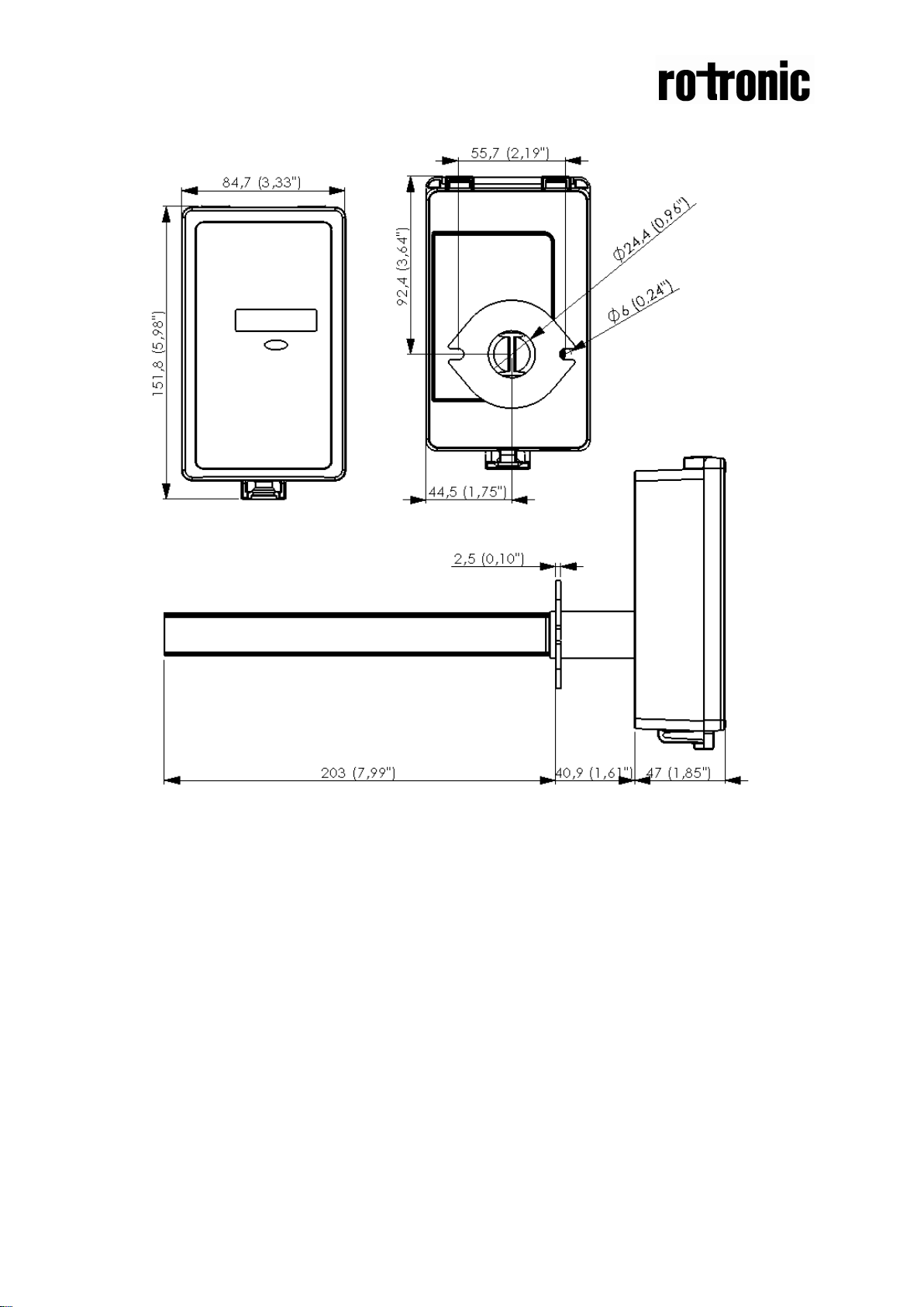
Dimensions
Figure 7 The dimensions of the sensor in mm and (inches)
 Loading...