

Page 1
E-M-AwTherm-V1.1
Rotronic AG
Bassersdorf, Switzerland
Document Type
Document code Unit
AwTherm: Water Activity at Controlled Temperature
Document title
Instruction Manual Version 1.1
© 2009-2010; Rotronic AG E-M-AwTherm v1.1
Instruction Manual
Page 2

E-M-AwTherm-V1.1
Rotronic AG
Bassersdorf, Switzerland
Advisory Notice
Document Type
Document code Unit
AwTherm: Important notice before first use
Document title
Contents of the Standard Supply Package:
• AwTherm stabilised temperature water activity meter with either PS-14 or PS-40 sample
cup holder
• HW4-P-Quick-V3 software code sticker
• MicroUSB cable for connection to HW4
• MicroUSB memory stick including HW4 and User Manual
• Power cables for UK or US/EU/CH
© 2009-2010; Rotronic AG E-M-AwTherm v1.1
Page 3

E-M-AwTherm-V1.1
Rotronic AG
Bassersdorf, Switzerland
Table of Contents
Document Type
Document code Unit
AwTherm: Table of Contents
Document title
1 Scope of Document ................................................................................................................ 1
1.1 Introducing the AwTherm ...................................................................................................... 1
1.2 Measuring Technology ........................................................................................................... 1
1.3 Calibration .............................................................................................................................. 1
2 Setting up the AwTherm ........................................................................................................ 2
2.1 Physical Location .................................................................................................................... 2
2.2 Electrical Supply ..................................................................................................................... 2
2.3 AwTherm Assembly ............................................................................................................... 4
2.4 Sample cup size ...................................................................................................................... 5
3 AwTherm Operation .............................................................................................................. 6
3.1 Switching On .......................................................................................................................... 6
3.2 AwTherm Interface ................................................................................................................ 7
3.2.1 Basic Navigation ........................................................................................................ 8
3.2.2 Main Menu ................................................................................................................ 9
3.2.3 AwTherm Settings ................................................................................................... 10
3.2.4 Setting the AwTherm Set Point Temperature ......................................................... 13
3.3 Making Measurements ........................................................................................................ 14
3.3.1 Starting a measurement run ................................................................................... 16
3.3.2 AwE Mode ............................................................................................................... 17
3.3.3 AwQ Mode .............................................................................................................. 18
3.4 Switching off the AwTherm ................................................................................................. 19
3.5 Preparing the Unit for Transit or Storage ............................................................................ 20
4 Sample preparation ............................................................................................................. 21
4.1 Protection from environment .............................................................................................. 21
4.2 Sample size and temperature equilibration time ................................................................ 21
4.3 Best Practices ....................................................................................................................... 21
4.3.1 Precondition samples to measurement temperature ............................................ 21
4.3.2 Avoid condensation................................................................................................. 21
4.3.3 Define procedures ................................................................................................... 22
5 PC Software ......................................................................................................................... 22
5.1 HW4 ..................................................................................................................................... 22
5.2 HW4 Support ........................................................................................................................ 22
6 Servicing and Maintenance .................................................................................................. 23
6.1 AwTherm Calibration ........................................................................................................... 23
6.1.1 Remove measuring head for calibration ................................................................. 23
6.1.2 Calibrate in Hygrogen2 ............................................................................................ 26
6.2 AwTherm Cleaning ............................................................................................................... 26
6.2.1 External surfaces ..................................................................................................... 26
6.2.2 Filter ........................................................................................................................ 26
6.2.3 Chamber .................................................................................................................. 27
6.3 Annual Servicing of AwTherm .............................................................................................. 28
6.4 Firmware Updates ................................................................................................................ 29
A1: AwTherm / Screen Messages ................................................................................................. 31
A2: AwTherm Specifications ........................................................................................................ 32
A3: AwTherm Order Codes .......................................................................................................... 33
© 2012; Rotronic AG E-M-AwTherm v1.1
Page 4

E-M-AwTherm-V1.1
Rotronic AG
Bassersdorf, Switzerland
Table of Contents
Document Type
Document code Unit
AwTherm: Table of Contents
Document title
A4: AwTherm Environmental Conditions ..................................................................................... 33
A5: Electrical Specifications ......................................................................................................... 33
A6: Battery disposal and replacement ......................................................................................... 34
B1: AwTherm Warranty Statement .............................................................................................. 35
B2: Manufacturer & Service Centre Contact Information .............................................................. 36
© 2012; Rotronic AG E-M-AwTherm v1.1
Page 5

E-M-AwTherm-V1.1
Rotronic AG
Bassersdorf, Switzerland
Instruction Manual for Software
Version 1.1
Document Type
Document code Unit
AwTherm: Water Activity at Controlled Temperature
Document title
Page 1
1 Scope of Document
This instruction manual refers to AwTherm running software version Aw-v1.00. To determine the
software version your instrument is running please refer to the Device Info screen as shown in
Section 3.2.1. Updates are available on www.awtherm.com
. This manual refers to the operation,
care and maintenance of the instrument itself, and best practices when making measurements.
For theory, background and further information on water activity, please refer to
www.awtherm.com.
1.1 Introducing the AwTherm
AwTherm is a temperature controlled water activity station – used for determining the water
activity of a sample, maintained at a known temperature. Water activity, which is used as a
measure of product consistency, is a parameter that is strongly dependent on temperature, and so
for consistent, repeatable measurements, it is vital to maintain known and stable thermal
conditions.
AwTherm is based on the same technology as the Rotronic HygroGen2 temperature and humidity
calibration suite of instruments which manipulate forced air to create highly stable thermal
conditions with minimal gradients within the measurement environment.
1.2 Measuring Technology
AwTherm uses a Rotronic HygroClip2 series probe to control and measure conditions.
1.3 Calibration
Calibration is an essential part of any reliable measurement process. AwTherm has a removable
measuring head which can be removed entirely (see Section 6.1.1) for calibration of both Aw and
Temperature parameters against references traceable to National Standards, using for example a
HygroGen2 temperature and humidity calibration system. The removed head is attached to the
HygroGen2 or a PC running Rotronic HW4 software (see section 5) using a special cable (not
supplied). Alternatively, the Aw parameter only can be calibrated in situ using Rotronic Calibration
Salts and adjusted using HW4 running on a PC connected to the AwTherm via its micro USB port.
© 2012; Rotronic AG E-M-AwTherm v1.1
Page 6

E-M-AwTherm-V1.1
Rotronic AG
Bassersdorf, Switzerland
Instruction Manual for Software
Version 1.1
Document Type
Document code Unit
AwTherm: Water Activity at Controlled Temperature
Document title
Page 2
2 Setting up the AwTherm
2.1 Physical Location
To ensure correct operation please ensure that:
1. The unit is level and stable;
2. There is at least 15 mm clearance underneath and at least 100 mm at the back of the unit
to enable adequate air flow;
2.2 Electrical Supply
Power Isolation
The unit is supplied with a mains cord set. The unit should be disconnected from the electrical
supply before the unit is moved, cleaned or has water added or removed.
Earthing
This unit must be earthed. Provision for the safety earth is made through the electrical mains
connection (Figure 2, item 5) to which all parts of the unit requiring earthing are internally
connected. An earthed electrical supply is required.
Earth Leakage Current
Due to RF filtering there is an earth leakage current, within the limits specified in EN 610101:2001. This may affect mains power circuits protected by Residual Current Device (RCD) or
Ground Fault Detector (GFD) type circuit breakers (particularly if used in multiples or with other
equipment with an earth leakage current on the same supply circuit).
Over Current Protection
To protect the internal circuitry against excess currents, the mains supply to the unit must be
connected with the mains cord set provided with the unit and to an appropriate mains supply.
Voltage Rating
The unit is designed to work within the limits of a 110-230 VAC 50-60 Hz mains supply with voltage
fluctuations up to ± 10% of the nominal voltage. The unit is rated impulse withstand (over voltage)
category II of IEC 60364-4-443. Where occasional voltage transients over 2.5 kV are expected or
measured, it may be necessary that the power installation to the unit includes a transient limiting
device.
© 2012; Rotronic AG E-M-AwTherm v1.1
Page 7

E-M-AwTherm-V1.1
Rotronic AG
Bassersdorf, Switzerland
Instruction Manual for Software
Version 1.1
Document Type
Document code Unit
AwTherm: Water Activity at Controlled Temperature
Document title
Page 3
Mains Filtration
If there is risk of power spikes or breaks, it is recommended that an Uninterruptable Power Supply
(UPS) is used to provide continued power and mains filtration. This should be rated according to
the AwTherm power specifications (see Appendix A5: Electrical Specifications) and the time
required to run/shutdown during power outage.
Conductive Pollution
The unit is rated Pollution Degree 2 and must not be operated in environments where conductive
pollutants (for example carbon) may enter the unit (this includes excessive moisture ingress).
© 2012; Rotronic AG E-M-AwTherm v1.1
Page 8
E-M-AwTherm-V1.1
Rotronic AG
Bassersdorf, Switzerland
Instruction Manual for Software
Version 1.1
Document Type
1) Lid
14) Screen
Document code Unit
AwTherm: Water Activity at Controlled Temperature
Document title
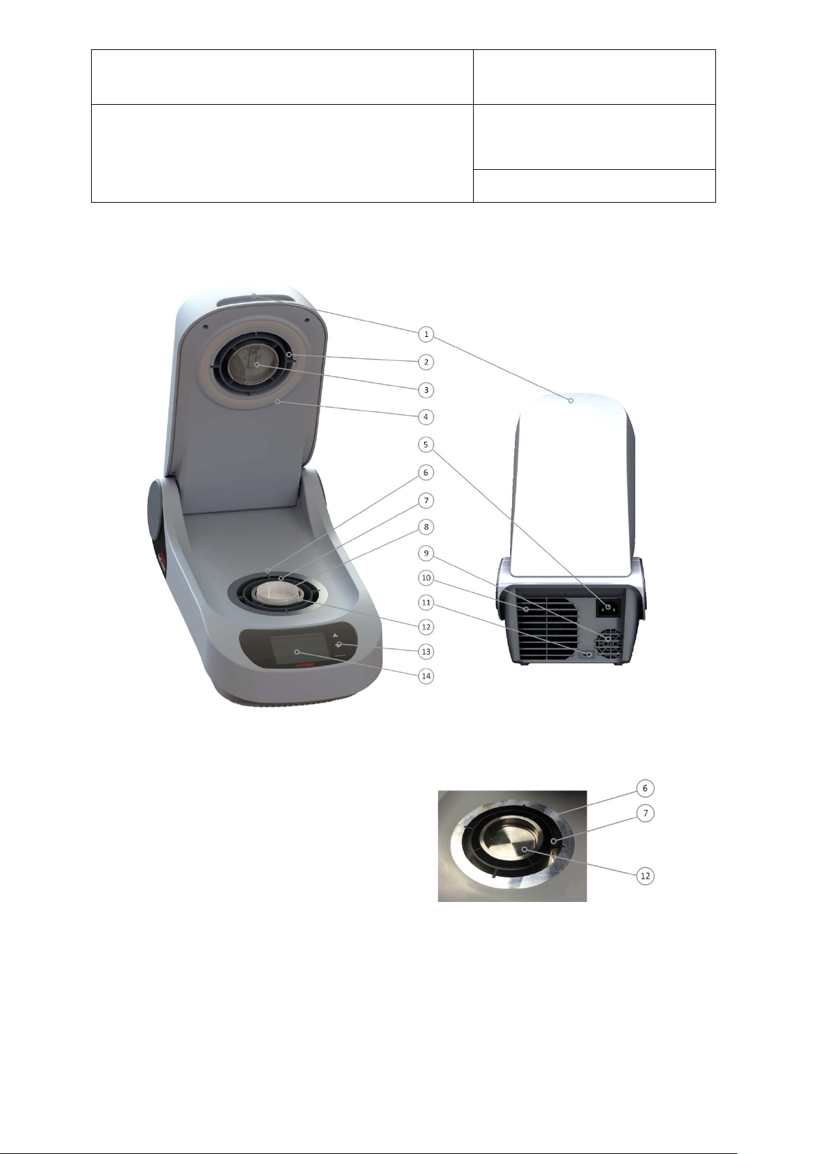
2.3 AwTherm Assembly
Page 4
Figure 2-1 - AwTherm Assembly (with lid open, front and rear view)
2) Removable measuring head
3) Sensor
4) Rubber seal
5) Electrical mains connection
6) Heat pump
7) Air flow sleeve
8) Sample cup
9) PSU fan outlet Heat pump fan outlet
Figure 2-2 Sample Chamber
10) Heat pump fan outlet
11) Micro USB port
12) Sample cup holder (PS14 or PS40)
13) Touch buttons
© 2012; Rotronic AG E-M-AwTherm v1.1
Page 9
E-M-AwTherm-V1.1
Rotronic AG
Bassersdorf, Switzerland
Instruction Manual for Software
Version 1.1
Document Type
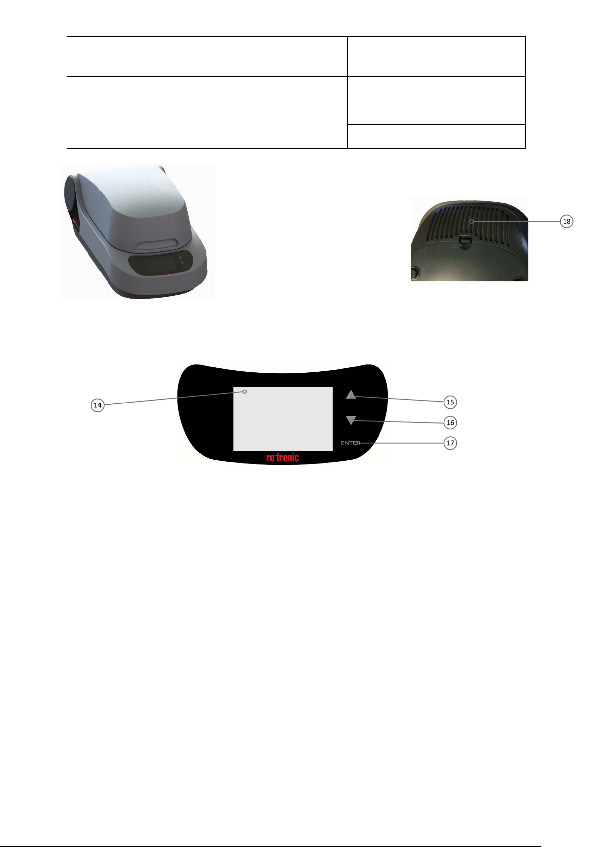
Figure 2-3 AwTherm Assembly (lid closed)
Figure 2-4 Removable filter (heat pump fan)
Figure 2-5 AwTherm Touch Interface
Document code Unit
AwTherm: Water Activity at Controlled Temperature
Document title
Page 5
15) Touch Button (up)
16) Touch button (down)
17) Touch button (ENTER)
18) Removable heat pump fan filter
2.4 Sample cup size
AwTherm is available in either PS14 (14mm depth) or PS40 (40mm depth) sample cup holder sizes.
Alternative sample cup holders are available as accessories (see Section A3: AwTherm Order
Codes).
Note that sample equilibrium time is dependent on the sample space, and so the selection of
sample cup size should be the smaller PS14 size where possible. For example powders and liquids
would merit selecting the smaller PS14 size; samples that are impractical for this size, e.g. large
seeds and pet foods, would merit the larger PS40 sample cup.
© 2012; Rotronic AG E-M-AwTherm v1.1
Page 10
E-M-AwTherm-V1.1
Rotronic AG
Bassersdorf, Switzerland
Instruction Manual for Software
Version 1.1
Document Type
Document code Unit
AwTherm: Water Activity at Controlled Temperature
Document title
Page 6
3 AwTherm Operation
3.1 Switching On
1. Ensure the electrical mains supply is correctly plugged in and switched on.
2. Switch the unit on by pressing the ENTER button once.
3. The fans within the unit will switch on giving an immediate audible indication the unit is
powered.
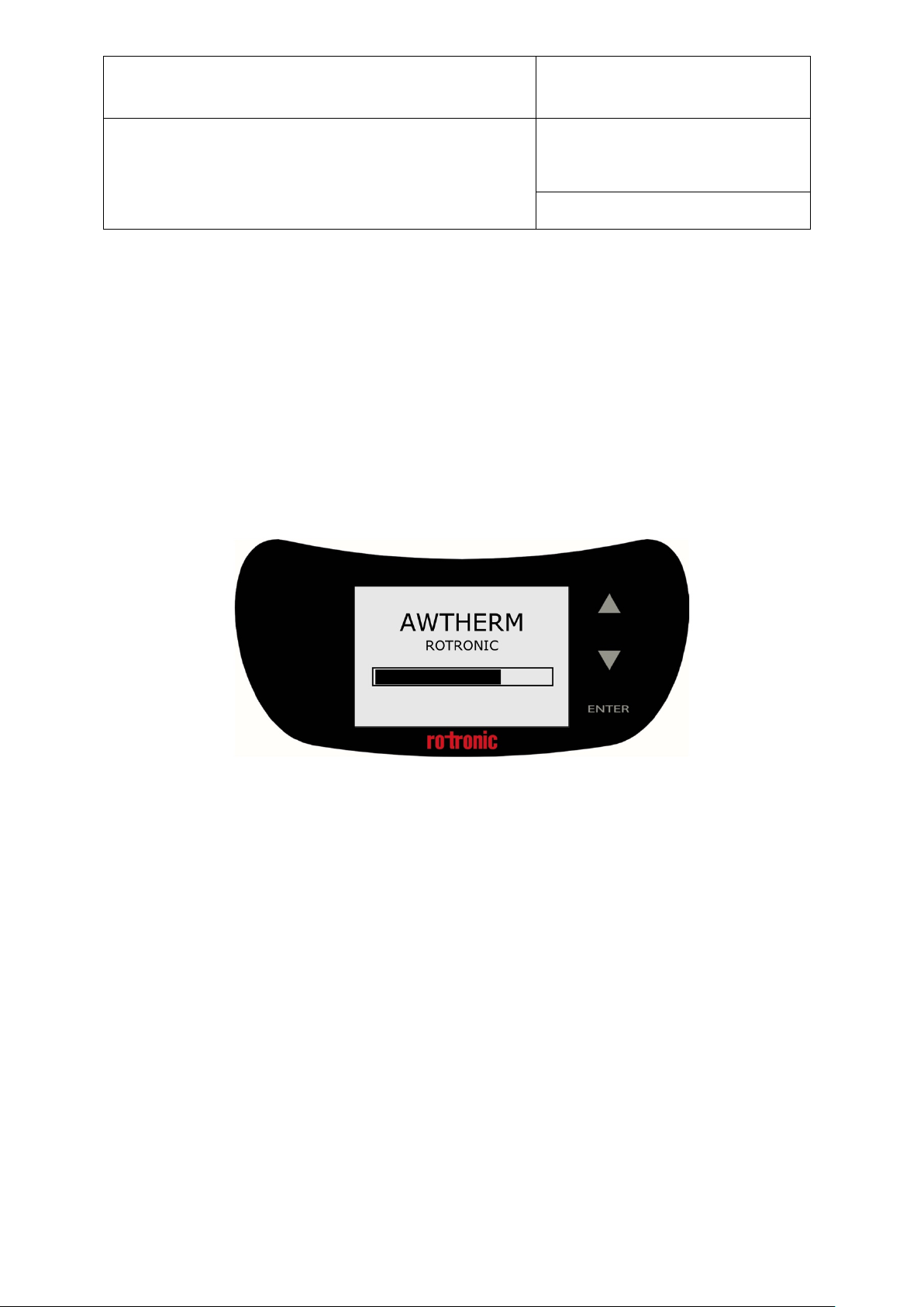
4. The loading screen will display (Figure 3-1)
5. The controller will power up and display the Top Level screen (as shown in Figure 3-2).
Figure 3-1 Boot screen
On power up:
• The temperature set-point defaults to the last set value.
• The temperature control defaults to automatic mode (controlling the temperature).
© 2012; Rotronic AG E-M-AwTherm v1.1
Page 11
E-M-AwTherm-V1.1
Rotronic AG
Bassersdorf, Switzerland
Instruction Manual for Software
Version 1.1
Document Type
Document code Unit
AwTherm: Water Activity at Controlled Temperature
Document title
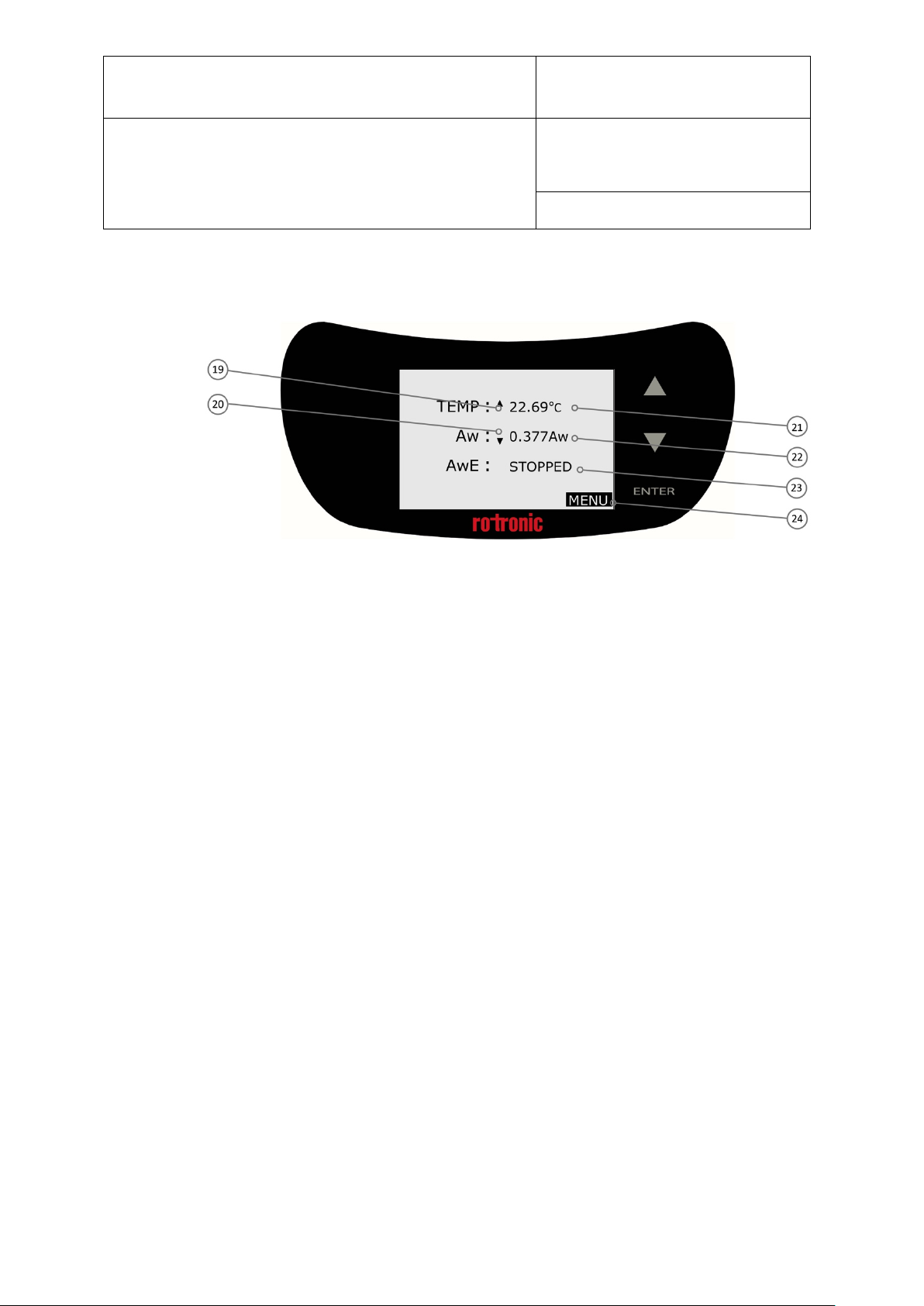
3.2 AwTherm Interface
Figure 3-2 AwTherm Top Level Screen
19) Temperature trend indication
20) Aw trend indication
21) Temperature field
22) Live Aw reading
23) Status field
24) MENU
Page 7
© 2012; Rotronic AG E-M-AwTherm v1.1
Page 12
E-M-AwTherm-V1.1
Rotronic AG
Bassersdorf, Switzerland
Instruction Manual for Software
Version 1.1
Document Type
Document code Unit
AwTherm: Water Activity at Controlled Temperature
Document title
Page 8
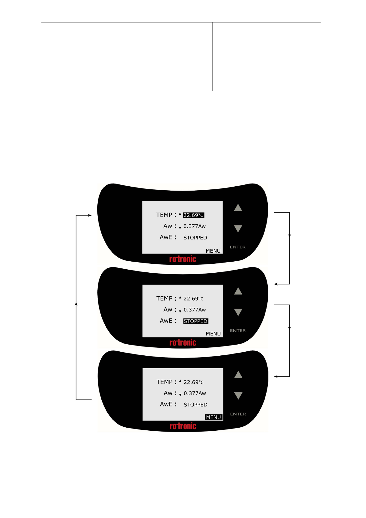
3.2.1 Basic Navigation
The AwTherm interface consists of a Top Level Screen with 3 fields which can be manipulated: (set
point) temperature, status, and device settings (Menu). Pressing the up or down arrow scrolls
through each of these, highlighting each one in turn. To select one, press the ENTER button. The
field will flash, and the functionality activated.
Figure 3-3 Basic Function Navigation
© 2012; Rotronic AG E-M-AwTherm v1.1
Page 13

E-M-AwTherm-V1.1
Rotronic AG
Bassersdorf, Switzerland
Instruction Manual for Software
Version 1.1
Document Type
Document code Unit
AwTherm: Water Activity at Controlled Temperature
Document title
Page 9
3.2.2 Main Menu
There are a number of AwTherm system and program settings that can be configured. To access
the settings, select MENU and press the ENTER button.
Figure 3-4 Access Device Settings Menu
NB For all menus and sub-menus, to return to the previous screen, scroll down to the RETURN
field and press the ENTER button.
© 2012; Rotronic AG E-M-AwTherm v1.1
Page 14

E-M-AwTherm-V1.1
Rotronic AG
Bassersdorf, Switzerland
Instruction Manual for Software
Version 1.1
Document Type
Document code Unit
AwTherm: Water Activity at Controlled Temperature
Document title
Page 10
Any adjustable parameter can be selected using the UP/DOWN and ENTER touch buttons in the
same manner as described for basic menu navigation. The parameter can be adjusted using the
UP/DOWN buttons and set by pressing the ENTER button.
Please note, by pressing and holding the up or down arrow keys, the speed of any numeric
incrementation will increase (autoscroll).
3.2.3 AwTherm Settings
i) Device Info displays the serial numbers of the unit itself, the AirChip Sensor and the firmware
version that the AwTherm is running.
Figure 3-5 Device Info
ii) Device Settings; Enable or disable temperature control (on by default), disable the Trend
Indication for temperature (19) and Aw (20) as shown in Figure 6, and configure the Aw measuring
mode: AwE or Aw-Quick (see section , below). Touch buttons can be set to make an audible sound
when activated, contrast adjusted (default optimal setting is 35%), and touchpad sensitivity
adjusted – from a value from 0-5. Please note, if touch pad has poor responsivity, try each
individual setting in turn until best results achieved.
Figure 3-6 Device Settings
© 2012; Rotronic AG E-M-AwTherm v1.1
Page 15

E-M-AwTherm-V1.1
Rotronic AG
Bassersdorf, Switzerland
Instruction Manual for Software
Version 1.1
Document Type
Document code Unit
AwTherm: Water Activity at Controlled Temperature
Document title
Page 11
iii) Time/Date Settings; Date and time can be set and displayed on the AwTherm (off by default).
Time/date is only displayed for convenience and is not used a part of data logging and therefore is
not crucial to the operation of the instrument. Data logging is performed using Rotronic HW4
software running on an external PC (see Section 5.1).
Please note the date format [DD/MM/YYYY] is fixed and cannot be changed.
Figure 3-7 Time/date Settings
iv) AwE Settings; the AwE Tolerance, Temperature tolerance, and process complete audible beep
volume can be configured here. Further details regarding AwE measurement mode are found in
Section
3.3.2.
Figure 3-8 AwE Settings
© 2012; Rotronic AG E-M-AwTherm v1.1
Page 16

E-M-AwTherm-V1.1
Rotronic AG
Bassersdorf, Switzerland
Instruction Manual for Software
Version 1.1
Document Type
Document code Unit
AwTherm: Water Activity at Controlled Temperature
Document title
Page 12
v) AwQ Settings; the Aw-Quick dwell time and temperature tolerance, and process complete
audible beep volume can be configured here. Further details regarding AwQ measurement mode
are found in Section
3.3.3.
Figure 3-9 AwQ Settings
vi) Service; the AwTherm firmware can be updated via this menu using a Micro USB drive inserted
into the Micro USB port (11) on the rear of the AwTherm.
Select the Update Firmware field and change the NO to YES using the up or down arrow keys and
press ENTER. Further details about updating the firmware are found in Section 6.4. There is also an
indication of the internal CMOS battery condition.
© 2012; Rotronic AG E-M-AwTherm v1.1
Figure 3-10 Service
Page 17

E-M-AwTherm-V1.1
Rotronic AG
Bassersdorf, Switzerland
Instruction Manual for Software
Version 1.1
Document Type
Document code Unit
AwTherm: Water Activity at Controlled Temperature
Document title
Page 13
3.2.4 Setting the AwTherm Set Point Temperature
Figure 3-11 AwTherm Top Level Screen
With the Temperature Control parameter turned on (Section 3.2.3), and the lid (1) closed, the
AwTherm will control the temperature of the sample chamber environment (12). The heat pump
(6) controls the temperature of the air which is circulated through the airflow sleeve (7) around
the outside the walls of the sample chamber.
To set the temperature, from the Top Level screen (Figure 3-11), use the up and down arrows to
select the Temperature parameter. Press ENTER; the temperature parameter will flash (Figure 3-
12) and the label will change to SP (set point).
Use the UP/DOWN touch buttons to adjust the value to the desired temperature and press ENTER
to accept it.
© 2012; Rotronic AG E-M-AwTherm v1.1
Figure 3-12 Select Temperature parameter
Page 18

E-M-AwTherm-V1.1
Rotronic AG
Bassersdorf, Switzerland
Instruction Manual for Software
Version 1.1
Document Type
Document code Unit
AwTherm: Water Activity at Controlled Temperature
Document title
Page 14
Figure 3-13 Define new Set Point Temperature
AwTherm will now control the temperature of the chamber to the new temperature. The time it
takes for the chamber to reach the temperature will depend on the ambient conditions, and the
initial and set point temperatures. Depending on the magnitude of the temperature change
required, the instrument will slightly overshoot, before coming back and stabilising. The Trend
Indicator (19) will show whether the unit is heating or cooling. When stable (to within the defined
AwE/AwQ temperature tolerance – see Section 3.3) the Trend Indicator will display up and down
indicators simultaneously.
Note that the chamber will reach a stable set point temperature before the sample, depending on
the initial temperature of the sample. See Sample Preparation: best practices and operational
considerations (Section 4.3) below for further details and advice.
3.3 Making Measurements
AwTherm features two modes for measuring water activity.
● AwE mode:
In this mode AwTherm monitors the stability of both temperature and humidity. The
measurement is automatically ended as soon as both humidity and temperature reach
equilibrium. The natural (or static) equilibration of most products typically requires from 15 to 60
minutes and can take as long as a couple of hours.
© 2012; Rotronic AG E-M-AwTherm v1.1
Page 19

E-M-AwTherm-V1.1
Rotronic AG
Bassersdorf, Switzerland
Instruction Manual for Software
Version 1.1
Document Type
Document code Unit
AwTherm: Water Activity at Controlled Temperature
Document title
Page 15
● AwQuick mode:
In the AwQuick mode, AwTherm uses an algorithm to project the full equilibrium value (water
activity) of the measured product. The measurement is automatically ended and typically requires
typically about 5 minutes. AwTherm performs the following tasks:
1) The value of the humidity signal is constantly monitored
2) The stability of the temperature signal is constantly monitored
3) After an initial period of time (dwell time), AwTherm uses the humidity data to project the end
value of the equilibration process (water activity). The measurement ends automatically as soon
as the projected Aw value is stable.
With the dwell time set to 4 minutes, measurements typically require about 5 minutes. When
temperature conditions are stable (both at the product and probe), the measurement obtained
with the AwQuick mode is generally within ± 0.005 aw of the measurement that would be
obtained by waiting for full equilibration (AwE mode).
Aw mode can be selected in Device Settings as described above (Section 3.2.3). Load your sample
into the instrument, following the guidelines as outlined in Section 4.
© 2012; Rotronic AG E-M-AwTherm v1.1
Page 20

E-M-AwTherm-V1.1
Rotronic AG
Bassersdorf, Switzerland
Instruction Manual for Software
Version 1.1
Document Type
Document code Unit
AwTherm: Water Activity at Controlled Temperature
Document title
Page 16
3.3.1 Starting a measurement run
To start a measurement run, at the Top Level screen, select the status field and press ENTER.
Figure 3-14 Select status field
Then use the UP/DOWN touch buttons to and select START, and then press ENTER.
The measurement run will now begin.
At the end of the run, the AwTherm will sound an audible beep (if so configured, see Section 3.2.3)
and hold the values on the screen, displaying FINISHED in the status field.
The following section describes the operation of each mode, AwE and AwQ as a flowchart.
© 2012; Rotronic AG E-M-AwTherm v1.1
Figure 3-15 Select START and press ENTER
Page 21

E-M-AwTherm-V1.1
Rotronic AG
Bassersdorf, Switzerland
Instruction Manual for Software
Version 1.1
Document Type
Document code Unit
AwTherm: Water Activity at Controlled Temperature
Document title
3.3.2 AwE Mode
Page 17
Figure 3-16 AwE process flowchart
© 2012; Rotronic AG E-M-AwTherm v1.1
Page 22

E-M-AwTherm-V1.1
Rotronic AG
Bassersdorf, Switzerland
Instruction Manual for Software
Version 1.1
Document Type
Document code Unit
AwTherm: Water Activity at Controlled Temperature
Document title
3.3.3 AwQ Mode
Page 18
Figure 3-17 AwQ process flowchart
© 2012; Rotronic AG E-M-AwTherm v1.1
Page 23

E-M-AwTherm-V1.1
Rotronic AG
Bassersdorf, Switzerland
Instruction Manual for Software
Version 1.1
Document Type
Document code Unit
AwTherm: Water Activity at Controlled Temperature
Document title
Page 19
3.4 Switching off the AwTherm
To turn off AwTherm, press and hold the ENTER touch button until the Shutting Down screen
appears and the progress bar has completed.
To cancel the shutdown process at any time, simply stop pressing the ENTER touch button.
Figure 3-18 Shutting Down screen
DO NOT switch off at the wall before the AwTherm has shutdown.
DO NOT switch off at the back of the AwTherm before it has shutdown.
© 2012; Rotronic AG E-M-AwTherm v1.1
Page 24

E-M-AwTherm-V1.1
Rotronic AG
Bassersdorf, Switzerland
Instruction Manual for Software
Version 1.1
Document Type
Document code Unit
AwTherm: Water Activity at Controlled Temperature
Document title
3.5 Preparing the Unit for Transit or Storage
If the AwTherm needs to be shipped, always use the original double-layer cardboard and
foam packaging.
Page 20
© 2012; Rotronic AG E-M-AwTherm v1.1
Page 25

E-M-AwTherm-V1.1
Rotronic AG
Bassersdorf, Switzerland
Instruction Manual for Software
Version 1.1
Document Type
Document code Unit
AwTherm: Water Activity at Controlled Temperature
Document title
Page 21
4 Sample preparation
4.1 Protection from environment
Fundamentally any sample will try to come into equilibrium with its environment, so it is vitally
important to keep samples as protected from the ambient environment as possible – to avoid its
water activity changing before loading into the instrument. This is best achieved by placing the
sample in a Rotronic PS14 or PS40 sample cup with a lid in place until the sample is ready to be
placed in the instrument and its lid closed.
This is particularly important if the sample is chilled as vapour may condense on the sample, and
render any measurement invalid.
4.2 Sample size and temperature equilibration time
Adequate time should be allowed for the sample to reach temperature in order to make a valid
measurement. The time taken depends on the size, weight, and specific heat capacity of the
sample. Difficulties in knowing the sample has reached the required temperature throughout are
mitigated by consistency in procedures and practices as described in the following sections.
4.3 Best Practices
4.3.1 Precondition samples to measurement temperature
If the samples being tested are part of a process, if at all possible, make measurements at the
temperature that the sample comes out of the process, and minimize the time taken to load the
sample into the AwTherm.
4.3.2 Avoid condensation
If your sample is chilled below ambient or you need to make measurements at low temperatures,
there is a risk of condensation forming. Condensation can form on chilled samples or on the inside
of the AwTherm when the lid is open. As a guide in normal laboratory conditions, condensation
can form on surfaces that are <15°C. It may be necessary to place the AwTherm in a cooler (drier)
environment to prevent this occurring
© 2012; Rotronic AG E-M-AwTherm v1.1
Page 26

E-M-AwTherm-V1.1
Rotronic AG
Bassersdorf, Switzerland
Instruction Manual for Software
Version 1.1
Document Type
Document code Unit
AwTherm: Water Activity at Controlled Temperature
Document title
Page 22
4.3.3 Define procedures
Water activity is a qualitative measurement of product consistency, and so to record useful data, it
is vitally important to make measurements in a consistent way. Define procedures: dwell times,
tolerances, etc, and be consistent with their implementation.
5 PC Software
5.1 HW4
AwTherm is bundled with ROTRONIC HW4 logging software which can be loaded on any PC
running a Windows OS. Once installed simply connect the AwTherm to a PC via the MicroUSB port
with the supplied cable.
HW4 features include:
• Instrument configuration
• Data acquisition
• Measurement display and graphing
• Calibration and adjustment
For further details on the AwTherm operation from within HW4, please refer to the HW4
documentation http://www.rotronic.co.uk/productattachments/index/download?id=949
5.2 HW4 Support
Support for HW4 is available via email. Please contact support@rotronic.ch including your full
contact details, the AwTherm serial number and HW4 product key, and a description of your query
or problem. You will receive a response within a maximum of two working days.
© 2012; Rotronic AG E-M-AwTherm v1.1
Page 27

E-M-AwTherm-V1.1
Rotronic AG
Bassersdorf, Switzerland
Instruction Manual for Software
Version 1.1
Document Type
Document code Unit
AwTherm: Water Activity at Controlled Temperature
Document title
Page 23
6 Servicing and Maintenance
6.1 AwTherm Calibration
A unique feature of the AwTherm is the ability to remove the entire head to calibrate both the Aw
and temperature sensors.
Alternatively, AwTherm can be calibrated in-situ for Aw using Rotronic calibration salts.
6.1.1 Remove measuring head for calibration
© 2012; Rotronic AG E-M-AwTherm v1.1
Page 28

E-M-AwTherm-V1.1
Rotronic AG
Bassersdorf, Switzerland
Instruction Manual for Software
Version 1.1
Document Type
Document code Unit
AwTherm: Water Activity at Controlled Temperature
Document title
Page 24
© 2012; Rotronic AG E-M-AwTherm v1.1
Page 29

E-M-AwTherm-V1.1
Rotronic AG
Bassersdorf, Switzerland
Instruction Manual for Software
Version 1.1
Document Type
Document code Unit
AwTherm: Water Activity at Controlled Temperature
Document title
Page 25
© 2012; Rotronic AG E-M-AwTherm v1.1
Page 30

E-M-AwTherm-V1.1
Rotronic AG
Bassersdorf, Switzerland
Instruction Manual for Software
Version 1.1
Document Type
Document code Unit
AwTherm: Water Activity at Controlled Temperature
Document title
Page 26
6.1.2 Calibrate in Hygrogen2
To minimise AwTherm downtime, alternative measuring heads can be fitted in place of the
existing head while it is being calibrated. To order spare heads, see Appendix A3: AwTherm Order
Codes.
6.2 AwTherm Cleaning
Prior to cleaning, the unit should be disconnected from the electrical mains supply.
6.2.1 External surfaces
The external surfaces of the AwTherm may be cleaned with a lint-free cloth dampened with a mild
soap solution. Care must be taken not to allow fluids into any of the apertures on the unit.
The fan inlet filter can be cleaned using a vacuum cleaner to remove any particulates.
6.2.2 Filter
© 2012; Rotronic AG E-M-AwTherm v1.1
Page 31

E-M-AwTherm-V1.1
Rotronic AG
Bassersdorf, Switzerland
Instruction Manual for Software
Version 1.1
Document Type
Document code Unit
AwTherm: Water Activity at Controlled Temperature
Document title
Page 27
6.2.3 Chamber
Periodically it is recommended that the internal surfaces of the AwTherm chamber. The bottom
half can be removed and placed in a dishwasher.
© 2012; Rotronic AG E-M-AwTherm v1.1
Page 32

E-M-AwTherm-V1.1
Rotronic AG
Bassersdorf, Switzerland
Instruction Manual for Software
Version 1.1
Document Type
Document code Unit
AwTherm: Water Activity at Controlled Temperature
Document title
Page 28
6.3 Annual Servicing of AwTherm
The unit does not require routine user maintenance beyond that described in this Section.
Under no circumstance should the unit be opened by personnel unauthorised by the
manufacturer. Doing so will void the manufacturer’s warranty, and expose potentially
dangerous electrical hazards.
© 2012; Rotronic AG E-M-AwTherm v1.1
Page 33

E-M-AwTherm-V1.1
Rotronic AG
Bassersdorf, Switzerland
Instruction Manual for Software
Version 1.1
Document Type
Document code Unit
AwTherm: Water Activity at Controlled Temperature
Document title
Page 29
6.4 Firmware Updates
To update the AwTherm firmware, select the Service menu, as described in Section 3.2.3 (vi), and
change the default ‘NO’ to ‘YES’ and press ENTER to continue.
The AwTherm will ask for a pen drive. Insert a micro USB stick loaded with the desired firmware in
its root directory. The firmware will be a file called “AW_image.hex”
Select ‘YES’ and press ENTER to continue. The AwTherm will restart.
© 2012; Rotronic AG E-M-AwTherm v1.1
Page 34

E-M-AwTherm-V1.1
Rotronic AG
Bassersdorf, Switzerland
Instruction Manual for Software
Version 1.1
Document Type
Document code Unit
AwTherm: Water Activity at Controlled Temperature
Document title
The AwTherm will verify the firmware image and re-flash its memory.
Page 30
The software will start as normal. You can then check the new software version in Device Info as
detailed in Section 3.2.3(i).
© 2012; Rotronic AG E-M-AwTherm v1.1
Page 35

A1: AwTherm / Screen Messages
Should the AwTherm fail to communicate with the sensor head, a Hardware Diagnostic page will
display.
Page 36

General
Device type
Temperature-stabilized water-activity measure
ment
Operating conditions
1..40 °C (34..107 °F)
Measurement range
0.005…1.000 aw
±0.1 °C (±0.18 °F)
Power supply
110..230 V / 50..60 Hz
Display
8-line LCD with touch operation
Sample sizes
Variable (14 mm / 40 mm)
Technical Information
Current Consumption
≤
2 A Temperature-control range
0..60 °C (32..140 °F)
Temperature stability
±0.01 °C/min (±0.018 °F/min)
Chamber-temperature gra
dient
<0.1 °C (<0.18 °F)
Firmware update
Via USB port
Functions
HW4-compatible
Yes (v 3.6.0 and higher)
aw-Quick function
Yes
Interface
Micro USB
ROTRONIC humidity standards (via HW4)
Trend indicator
Yes
Probes
Sensor
HYGROMER® IN-1
Maintenance / Calibration
Annual calibration (recommended)
Long-Term Stability
<0.01 aw/year
Temperature sensor
Pt100, DIN 1/3 Class B
Approval / Conformity
Standards
ISO 21807
IEC/ EN 61010-1:2010
IP protection
IP21
Housing / Mechanical parts
Housing material
PC / ABS
Housing dimensions
400 x 180 x 180 mm
AwT-PS40: Ø46 x 40 mm
Weight
4200 g
A2: AwTherm Specifications
Accuracy
Calibration / Adjustment
±0.005 aw
Aw & Temperature:
HG2-S (probe removed with AwT-CAL)
Aw:
CE / EMC
Sample container holder dimensions
EMC 2004/108/EC
AwT-PS14: Ø46 x 14 mm
Page 37

AW-Therm
AwTherm-PS14
AwTherm Body incl. Standard AwT-MHS and AwT-PS14
AwTherm-PS40
AwTherm Body incl. Standard AwT-MHS and AwT-PS40
AW-Therm SET
AwTherm-SET
AwTherm Body incl. Standard AwT-MHS and AwT-PS14 AND AwT-PS40
AWTherm Measuring Heads
AwT-MHS
AwTherm measurement head standard
AWTherm sample container holder
AwT-PS14
AwTherm sample holder for PS14 (ordered separately), depth 14mm
AwT-PS14
AwTherm sample holder for PS40 (ordered separately), depth 40mm
Sample container
PS-14
Pack of 100 sample containers for AwT-PS14
PS-40
Pack of 100 sample containers for AwT-PS40
A3: AwTherm Order Codes
A4: AwTherm Environmental Conditions
This standard applies to equipment designed to be safe at least under the following
conditions:
• For indoor use only
• Altitude up to 2000 m
• Ambient temperature 5°C to 40°C
• Maximum relative humidity 80 % for temperatures up to 31 °C decreasing
linearly to 50 % Relative Humidity at 40 °C
• Pollution degree 2
A5: Electrical Specifications
• Input voltage is from 90VAC to 264VAC; Auto Ranging
• Input Frequency range from 47Hz to 63Hz
• Input current is 3.5A at 100VAC or 1.5A at 240VAC
• Power inlet IEC socket
Page 38

A6: Battery disposal and replacement
Batteries must not be disposed of as ordinary refuse. Please use a local battery
recycler.
Replacement batteries are available from Rotronic. These are Lithium rechargeable
batteries and must only be replaced with the same type. The replacement battery
will be supplied with plastic tweezers; do not use a metal tool to remove the
battery as this will cause a short circuit. Be sure to insert the new battery using the
correct polarity as shown.
Use of a non-rechargeable battery, or incorrectly inserting the battery could lead to
explosion.
Page 39

B1: AwTherm Warranty Statement
ROTRONIC will grant a warranty for the AwTherm for a period of 24 months from the date of
delivery in respect of any evidenced faulty workmanship and materials. The warranty period is
extended by a further 24 months when the unit is serviced at a ROTRONIC approved service centre
24 months after the date of supply. Should the instrument be proven not to meet the published
specifications or to be contrary to contract upon inspection, the customer shall grant ROTRONIC
the opportunity hereunder of repairing the fault by returning the unit carriage paid to ROTRONIC.
Should the supply or delivery of any improvement or replacement not prove possible, the
customer may choose between having the purchase price reduced or in demanding the contract of
sale to be rescinded (conversion). Damage resulting from natural wear and tear, an act of God or
non compliance with the operating instructions shall be excluded from the warranty as well as
mechanical interference by the customer or by third parties with plant and equipment of
ROTRONIC without its written permission. No liability will be accepted for defects, damage or
injury caused due to installation not carried out in accordance with the manufacturer’s installation
instructions.
The instrument maintains a record of the usage and this may only be reset by an authorised
service centre; this will determine the warranty period granted.
Page 40

Manufacturer/UK Service
Switzerland Service Centre:
USA Service Centre:
Germany Service Centre :
France Service Centre:
China Service Centre:
B2: Manufacturer & Service Centre Contact Information
Centre :
Rotronic Instruments (UK) Ltd
Crompton Fields
Crompton Way
Crawley RH10 9EE
United Kingdom
Phone : +44(0)1293 571000
Fax : +44(0)1293 571008
www.rotronic.co.uk
instruments@rotronic.co.uk
Rotronic Messgeräte GmbH
Einsteinstrasse 17-23
76275 Ettlingen
Deutschland
info@rotronic.de
www.rotronic.de
Phone +49 7243 383 250
Fax +49 7243 383 260
Rotronic AG
Grindelstrasse 6
CH-8303
Bassersdorf
Switzerland
Phone +41 1 838 1144
Fax +41 1 837 0073
www.rotronic.ch
humidity@rotronic.ch
Rotronic s.a.r.l.
56, bd de Courcerin,
F-77183 Croissy Beaubourg
France
humidite@rotronic.fr
www.rotronic.fr
Phone +33 160 95 07 10
Fax +33 160 17 12 56
Rotronic Instrument Corp.
Suite 150
135 Engineers Road
Hauppauge, NY 11788,
USA
Phone +1 631 427 38 98
Fax +1 631 427 39 02
sales@rotronic-sa.com
www.rotronic-usa.com
Rotronic Shanghai
Representative Office
2B,Zao Fong Universe Building
No.1800 Zhong Shan West
Road,
200233 Shanghai
China
info@rotronic.cn
www.rotronic.cn
Phone +86 40 08162018
Fax +86 10 82254374
 Loading...