

Page 1

MODEL RTO FILLED SYSTEM
TEMPERATURE RECORDERS,
RPO PRESSURE RECORDERS &
RECORDERS CONTROLLERS
(ELECTRICAL CONTROL)
Instruction Manual
Introduction 1
Specification 1
Description of Operation 1
Receipt of Recorder 1
Dimensions and Fixing 2
Installation 2
Mounting 2
Access to Recorder 2
Electrical Connections 2
Process Connections 3
Operation 4
Fitting a Chart 4
Inking System 4
Set Point Adjustment 4
Zero Adjustment 5
Start-up Check 5
Start-up Procedure 5
Calibration 6
Maintenance 8
Replacing a Filled System 8
Replacing a Pressure System 8
Fault Finding 9
Spares List 10
The chart drive and control system on this system may be operated from
a mains voltage supply.
The mains must be switched off before any mechanical adjustments
(other than of the set pointer) or carrying out any maintenance or fault
finding procedures.
When making electrical adjustments observe the warning notes in the
text.
Page 2

Accuracy +/- 1 % FSD.
Ambient -20°C to +50°C
Chart Drive Synchronous electric, battery or mechanical
spring wound. 24 hour or 7 day.
(Other rotations on request).
Inking System Disposable fibre tipped pens.
Single pen: red. Two pen: red and blue.
Three pen: red, blue and green
Case Glass filled polyester resin.
Protection rated to IP55.
Window Acrylic.
Power Supply 200 to 250 volts, 50 Hz (60Hz available);
100 to 110 volts, 50 Hz (60Hz available).
Instruments without electrical control require no
power supply provided that a clockwork drive is
fitted.
Battery operated chart drives require 1.5 volt 'C'
type cell.
Electrical Alarm and Control
Contact Rating 0.1A at 250v A.C. (non inductive)
(when fitted) 0.01A at 250v D.C. (non inductive)
Relay contact 10A at 250v 50Hz.
rating: (when fitted)5A at 415v 50Hz.
Contact
Adjustment Range2% to 100%
Weight
(approx.) Single pen: 6.5kg (14.25 Ib)
Two pen: 7 kg (15.5 Ib)
Three pen: 7.5 kg (16.75 Ib)
Portable single pen: 8.6 kg (19 Ib)
The above weight includes 3 metres (10 ft)
of capillary. For each additional 3 metres add
0.25 kg (0.5 Ib).
Mounting Suitable for surface or panel mounting.
(Pipe mounting and portable options available)
For instruments fitted with Temperature Systems
Measuring Element
Rototherm thermal bourdon tube temperature
compensated.
Capillary Microbore stainless steel tube with 3mm
diameter stainless steel cover (type C1) as
standard, other capillaries are available.
Bulb and Stem Stainless Steel BS970 316 S16.
Fittings Compression gland (adjustable).
stainless steel 8S970 316 (1/2" BSP is
standard). Other BSP NPT API etc. are
available on request.
(Suitable for pressures up to 3.5 Bar).
For Instruments Fitted with Pressure Systems
Measuring Element
Stainless Steel or Phosphor Bronze Bourdon
tube or pressure capsule as applicable.
Connection
Standard 3/8" BSP male with nut and tail pipe suitable for
6.35mm (0.25") outside diameter tube or 3/8"
inside diameter tube.
Portable 3/8" BSP male with nut and tail pipe suitable for
6.35mm (0.25") outside diameter tube or 3/8"
inside diameter tube.
Receiver type 1/4" BSP female.
input 3-15 p.s.i.
(0.2 - 1 Bar)
The RTO and RPO series of instruments are designed to measure,
record and control process variables such as temperature,
pressure and humidity. A maximum of three measuring systems
can be provided in each instrument; a fluid expansion/gas
expansion system is used for temperature recording, a wet and
dry bulb system for humidity and a bourdon or diaphragm
capsule for pressure measurement. The measured values are
continuously recorded on a calibrated circular chart which is
rotated at a constant speed by a mechanical or electrical clock.
Control of the process variable is provided electrically.
Temperature Recorder
As the temperature rises, the fluid in the thermometer bulb
expands and partially uncoils the Bourdon tube fitted inside the
instrument. This movement is transferred by a mechanical linkage to
the pen arm which records the temperature on a calibrated chart.
Humidity Recorder - Wet and Dry Bulb
The relative humidity can be obtained from the temperatures
measured by the wet and dry bulb thermometer using hygrometric or
psychrometric tables.
Pressure Recorder
On medium and high pressure ranges an increase in pressure
partially uncoils a Bourdon tube fitted inside the instrument. This
movement is transferred by mechanical linkage to the pen arm
which records the pressure on a calibrated chart.
A capsule stack is fitted for low pressure ranges and the expansion
of the system resulting from an increase in pressure is transferred
by a mechanical linkage to the pen arm.
For vacuum range a contraction of the capsule stack results from
an increase in vacuum and this movement is transferred by a
mechanical linkage to the pen arm.
The temperature recorder complete with a packet of charts, case
keys and pen packs is dispatched in a protective casing which
should be preferably replaced after inspection, as protection until the
instrument is ready for installation.
The spare pen pack(s) are inside the protective case. The case
keys are attached to the bottom right hand mounting stud.
When fitted the capillary tubing between the bulb and recorder
is coiled for despatch purposes. Immediately prior to installation,
this tubing must be uncoiled carefully in order to avoid twisting or
kinking
To assist with inspection, a label attached on the inside face of
the case door states the instrument serial number, chart number,
ranges of each pen and the rotation speed of the chart drive. If
the chart drive is electrical the supply voltage is stated.
SPECIFICATIONS
1
INTRODUCTION
Description of Operation
Receipt of Recorder
Page 3
Ideally the site chosen should be free from dust, corrosive
fumes, vibration and extremes of temperature.
The instrument is suitably compensated against normal
ambient temperature variations.
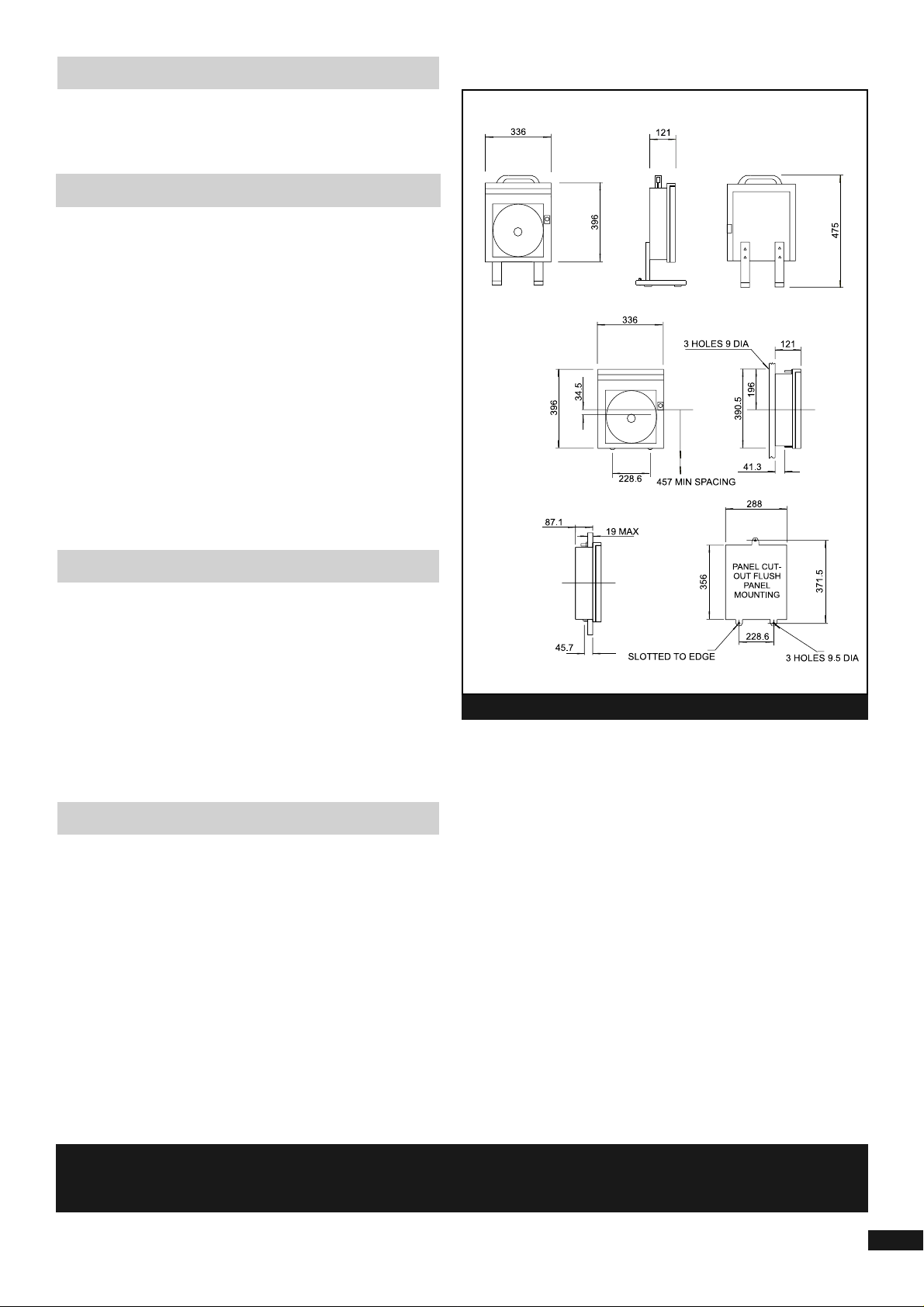
The recorder may be surface or flush panel mounted.
For surface mounting, remove the screws holding the three
brackets at the rear of the case, reverse and refit the brackets
with their ends projecting from the edges of the case.
The bracket with the keyhole slot must remain at the top of
the case.
Drill three holes in the mounting surface, of the size and at
the centres given in Fig. 1. Fit a screw (max. major diameter
6.35mm(0.25 inch)) in the top hole.
Locate the instrument on this screw and fit two smaller screws
through the remaining brackets.
For Flush Panel Mounting, make a panel cut-out to the
dimensions given in Fig 1. Drill the holes and slot to the cut-out
edge as shown. Remove the nuts and washers from the studs
projecting from behind the case flange, pass the recorder
through the cut-out and refit the washers and nuts to secure the
instrument.
To open the instrument door press the plunger of the door lock
and pull the door forward from the right. As the door is opened
the pen lifter raises the pen (or pens) away from the chart.
Remove the cotton thread that secures the pens to the pen lifter
for transit purposes.
To make electrical connections and to set contacts, remove the
chart plate by loosening the three retaining screws and carefully
lift out the chart plate via the finger hole (care is necessary to
avoid pen lifter interference with pens and control pointers).
Pull the bottom edge clear of the instrument and lower the chart
plate from behind.
Before making any electrical connections to the instrument
switch off the mains supply to be connected.
All electrical connections are made to terminal blocks in the
lower part of the case behind the chart plate.
Insert the leads through the cable glands in the underside of the
case and make connections shown on the terminal labels or the
wiring diagram supplied.
It is important to select the correct supply voltage connection.
The live line should be switched and fused with a 2 Amp fuse.
The mains supply should be earthed and connected at the
appropriate terminal within the recorder.
Alarm systems should have an independent power supply to
safeguard alarm operation in the event of mains failure.
ALARM SYSTEMS SHOULD HAVE AN INDEPENDANT POWER SUPPLY TO
SAFEGUARD ALARM OPERATION IN THE EVENT OF A MAINS FAILURE
2
Installation
Mounting
Access to Recorder
Electrical Connection
Fig. 1
all dimensions are in mm
Page 4
To avoid confusion on instruments with more than one
measuring system, capillary connections to the instruments are
- marked with the same colours as the inks used for the
corresponding pens.
Capillary Tubing
The tubing between the bulb and recorder should be routed so
that it is not subjected to large temperature changes and should be
supported in cleats. Bends must not be less than 25mm(1 inch) in
radius and under no circumstances must the tubing be cut.
Where the tubing is likely to be exposed to an extreme corrosive
atmosphere, the exterior should be treated with corrosion resistant
paint.
Immersion Types
The instrument bulb should be located where it is subject to the true
temperature of the measured medium. Temperature gradient within
the medium must be allowed for, and with bulbs allowing variable
depth of immersion (compression gland type), the bulb position
should be varied experimentally until the optimum position is found.
The full length of the sensitive portion must at all time be immersed
in the medium, but direct contact with the source of heat to the
medium must be avoided.
When securing the bulb in its location, it should be prevented from
twisting.
Where a pocket is supplied, this should be securely installed before
the bulb is inserted. It may be that the thermal response of a
pocketed bulb is improved by filling the intervening space with a
medium such as oil.
Capillary Type Bulb
This type of bulb should be installed by means of its end brackets
and to allow maximum circulation of air or gas around it, the coil
should be extended to a length of 610mm (2ft) or such that the
interval between the adjacent turns does not exceed 12.5mm (0.5
inch).
Any extension beyond this length may affect the zero reading at
the recorder. The bulb must be kept free of moisture.
Install the sensing elements (bulbs) where the humidity is to be
measured as described for temperature measuring instruments.
The wet bulb (red pen system) is kept moist by a fabric covering,
forming a wick which dips into a constant level water bath.
A distilled water supply tank should be connected to the inlet
feed pipe with a head of between 1 and 6 metres.
Use 0.25" (6.35mm) o.d. or 3/8"(9.5mm) bore solid drawn copper
tubing that has been well annealed cleaned and pressure test before
soldered into or over the tail pipe.
The solder joint and other joints in the pipeline must be secure and
leak proof. The use of PTFE tape is recommended for all thread
connections. Ensure that the sealing washer is in place when
assembling the tail pipe to the instrument connector.
A suitable seal must be inserted in the system if the medium
under pressure is liable to have a corrosive action on the
pressure element.
Gauge and Absolute Pressure Controllers.
It is recommended that a needle valve be installed in the pressure
line close to the instrument to enable pressures to be admitted
gradually. It can also be used to damp out any pressure pulsations.
A second needle valve, situated between the damping valve a
the controller, can be arranged to vent the instrument to enable
the zero to be checked.
This valve must not be fitted where steam or corrosive gases or
liquids are present.
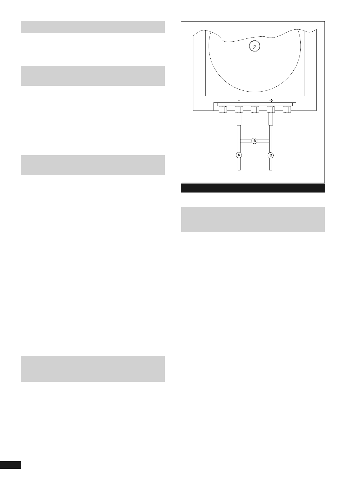
Differential Pressure Controllers
There are two pipes to each differential pressure measuring unit.
Connect the lower pressure to the (-) connector and the high
pressure to the (+) connector. Three needle valves should be
installed close to the controller, one isolating valve in each pressure
line and one balancing valve as arranged in figure 2.
3
PROCESS CONNECTIONS
FOR INSTRUMENTS FITTED WITH
TEMPERATURE SYSTEMS
LOCATION OF BULB
(DETECTING ELEMENT)
PROCESS CONNECTIONS - HUMIDITY
MEASURING ELEMENTS
(WET AND DRY BULBS)
Fig. 2
PROCESS CONNECTIONS -
FOR INSTRUMENTS FITTED WITH
PRESSURE SYSTEMS
Page 5

For Recorders Fitted with an Electrical Chart Drive
Release the chart clamp as shown in figure 3. Fit the chart onto
the spindle of the clamp and rotate the chart until the pen tip is on
the correct time line. Lower the chart clamp and press it firmly
to ensure that the locating pips pierce the chart.
Place the chart beneath the outer chart clips.
The writing system uses the fibre pen capsules.
A recess on the capsule fits onto the pen arm and the pen capsules
are easily replaced when the ink is exhausted. To fit a capsule, pull
the arm gently clear of its mountings, slide off the used capsule and
replace it with a new one of the appropriate colour.
Where there are two or more measuring systems, different colour
inks are used to distinguish the traces. The fibre tip is protected by a
plastic cap, which should be removed by pulling in line with its
length, gripping the end only and gently twisting.
Do not bend. The upper pen (red) has a long fibre Tip compared to
the lower pen (blue) which has a short fibre tip.
On instruments fitted with a third measuring system, the third pen
(green) has the longest fibre tip.
All recorders and recorder controllers are fitted with disposable
fibre tipped pens. These pens slide onto the pen arms.
The recorder pen arm is removable from the pen mechanism see
fig. 4. It is advisable to remove the pen arm from the mechanism of
recorders when fitting new pens because of the possibility of undue
forces being applied to the mechanism thus causing a possible error
shift.
Recorder controller pen arms are fixed to the mechanism and
must remain in situ when changing pens.
For instruments fitted for Temperature Systems
Disconnect Mains Power Supply
For low alarm set point slacken the lock nut securing the low contact
adjustment screw and screw the adjustment until the moving contact
just makes contact with the low contact at the point required, the set
point. Re-tighten the lock nut.
For high alarm set point, slacken the lock nut, securing the high
contact adjustment screw and screw the adjustment until the moving
contact just makes contact with the low contact at the point required,
the set point. Re-tighten the lock nut.
Note: For the low alarm, unscrewing the adjustment reduces the
set point and for the high alarm, unscrewing the
adjustment increases the set point
Note: After making any zero adjustments to instruments fitted
with control or alarm contacts the set point operating point must
be checked and adjusted as described in the section.
Zero Adjustment - temperature recorders and wet and dry bulb
humidity instruments see Fig 6.
All instruments are calibrated against reference standards before
despatch but should be checked in case of slight disturbance
during transit. Immerse a standard thermometer with a bulb and
check the readings. If adjustment is necessary open the door and
rotate the small knurled nut in Fig 6. to bring the pen
to the correct reading.
4
FITTING A CHART
INKING SYSTEM
Fig. 3
Fig. 4 Pen Arm / Ink Cartridge Fitting / Removal
Fig. 5. Alarm Contact Adjustment
SET POINT ADJUSTMENT (Fig. 5)
ZERO ADJUSTMENT (TEMPERATURE)
OPERATION
Page 6

For instruments fitted with Pressure Systems
Disconnect Mains Power Supply
For low alarm set point slacken the lock nut securing the low contact
adjustment screw and screw the adjustment until the moving contact
just makes contact with the low contact at the point required, the set
point. Re-tighten the lock nut.
For high alarm set point, slacken the lock nut, securing the high
contact adjustment screw and screw the adjustment until the moving
contact just makes contact with the low contact at the point required,
the set point. Re-tighten the lock nut.
Note: For the low alarm, unscrewing the adjustment reduces the
set point and For the high alarm, unscrewing the
adjustment increases the set point
Gauge Pressure
Vent the recorder to the atmosphere and check the reading of the
pen on the chart. If the pen does not read zero, adjust by means of
the zero nut (4 or 12).
Absolute Pressure
If the range covers atmospheric pressure, the accuracy can be
checked by venting the instrument to the atmosphere and checking
the reading against an accurate barometer.
If the range does not cover atmospheric pressure, a pressure
within this instrument range, measured against a standard pressure
gauge should be applied to the instrument.
Any adjustment is made by the zero nut (4 or 12).
Differential Pressure (Flg. 2)
To obtain a zero reading, open balance valve B and close isolating
valves A and C.
Before putting the recorder into operation make the
following checks to ascertain that it is correctly
installed and operational.
1. The pen(s) operate freely, write clearly on the chart and
pass each other without touching.
2. Measuring elements are correctly installed.
3. Measuring elements are indicating correctly.
If not, refer to zero adjustment.
4. Ensure that, in case of instruments with mechanical
clocks, the clock is running and that the correct electrical
connections have been made in instruments fitted with
electrical clocks.
5. Fit a new chart with its edge under the guide clips, set it to
the correct time line and clamp the centre fixing device
The procedure in the following paragraphs are for single pen or
dual pen instruments.
Refer to figure 7 for mechanism detail.
With the chart plate removed, cut a segment of chart and place on
the chart clarnp. Set the desired value pointer (1 or 2) to the
required value by means of the setting knob (3 or 4).
Move the actual value pen (5 or 6) until it just makes contact
with the switch arm (7).
Move the actual value pen (5 or 6) to the required deviation above
the desired value pointer (1 or 2) and adjust the high contact (9 or
10) until it just makes contact with the switch arm (7).
Low contact is set by moving the actual value pen (5 or 6) to the
required deviation below the desired value pointer (1 or 2) and
adjusting the low contact screw (8 or 11) until it just makes contact
with the switch arm (7).
Warning
Before adjusting the Contact Differential with the insulated spanner
provided, ensure that the mains supply is isolated and use a
continuity tester to establish switching points.
Be sure that all steps in the start-up check have
been completed.
1. Switch on the mains supply to the recorder.
2. Adjust set point on desired alarm/control value
(if applicable).
3. Switch on mains supply to external electric alarm/control
systems (if applicable).
5
SET POINT ADJUSTMENT
ZERO ADJUSTMENT (Fig. 6)
START-UP CHECK
Fig. 5. Alarm Contact Adjustment
CONTACT DIFFERENTIAL ADJUSTMENT FOR
TEMPERATURE AND PRESSURE RECORDERS
START-UP PROCEDURE
Page 7

Three adjustments are provided for calibration purposes:-
"Zero Adjustment" - to correct the lowest reading
"Range Adjustment" - to correct highest reading
"Scale Form Adjustment" - to correct midpoint reading
Warning
Unless the range is such that the same liquid can be used in all
baths the bulb should be wiped dry when transferring from one bath
to another.
This is particularly important when a "wide span" range; for example
0 to 450°C, where the "low point" bath would hold water and the
"high point" bath fusible salts. In such a case, it is dangerous to
insert a bulb wet with water into the salts bath.
Note
In transferring from one temperature to another there will be a
short time lag before the bulb reaches the bath temperature.
This will vary according to the range. Also, transferring a "cold"
bulb to a hot bath will affect the temperature of the bath liquid
until the thermostat has corrected for this.
Therefore, always check the bath temperature against a certified
test thermometer before taking a reading of the pen position
and making adjustments. This also applies when taking an Ice
point or that of the boiling water in baths not thermostatically
controlled.
Ice Point
The bulb should be immersed in a bath of clean crushed ice with a
large percentage of free water. The ice must not contain any salt or
other contaminant and the bulb should be cleaned before immersion. It is good practice to check the temperature with a mercury-inglass thermometer.
Boiling Point of Water
The boiling point of water varies with the barometric pressure and a
mercury-in-glass thermometer should be used to check the actual
temperature of the bath.
The bulb must not be allowed to come into contact with the heating
source.
In the following paragraphs,
the operation numbers refer to Fig 8.
1. Adjust zero nut (4 or 14) until the range adjustment screw
(5 or 6) is at right angles to the screwed link (7 or 8).
Ease the pen arm boss (12) from the pen arm spindle
taper and set the pen to the centre line of the chart.
Press the boss firmly on the taper when positioned. When
making this adjustment, do not turn the pen arm boss on
its taper except against the slightest friction, or the pen
arm retaining prongs will be bent.
2. Immerse the bulb in the low temperature bath, allow
sufficient time for the bulb to attain the bath temperature
and adjust the zero nut (4 or 14) until the pen arm
registers the temperature shown on the test thermometer.
3. Transfer the bulb to the high temperature bath, allow
sufficient time for the bulb to attain the bath temperature
and note the position of the pen.
4. If the pen rests below the correct line, halve the error by
adjusting the ranging screw (5 or 6) anticlockwise. If the
pen rests above the line, adjust the ranging screw (6)
clockwise to bring the pen to the top of the chart.
5. Return the bulb to the low temperature bath and adjust the
zero nut (4 or 14) to bring the pen to the correct line.
6. Check the top point and if still in error, repeat steps 4
and 5 until the bottom points are correct.
7. Transfer the bulb to the midpoint bath. If the pen reads
correctly, the instrument can be put into service. If there is
an error note its magnitude and proceed to step 8.
8. Ease the pen arm boss (12) from the spindle taper and set
the pen approximately 8 times the value of of the error on
the opposite side of the mid-chart line.
Press the boss firmly on the taper.
This adjustment is not possible on instruments fitted
with differential contact mechanisms as the pen boss
is factory set.
9. Return the bulb to the low temperature bath and adjust the
zero nut (4 or 14) to bring the pen to the correct value on
the scale.
10. Transfer the bulb to the midpoint bath. If not correct,
repeat step 8 (the multiple of 8 is a value, which in most
cases, will correct the midpoint error). However it may be
varied according to the results obtained.
11. Test the high temperature and if necessary, repeat steps
4, 5 and 8.
12. When all points are correct, remove the pen arm as
Fig. 4, position a centre punch in the hole in the centre
of the pen arm boss (12) and with a 4 ounce hammer
lightly applied, fix the boss on the spindle spear.
13. Replace the pen arm and return the instrument to service.
FOR INSTRUMENTS FITTED WITH
TEMPERATURE SYSTEMS
FOR INSTRUMENTS FITTED WITH
TEMPERATURE SYSTEMS
CALIBRATION
6
Page 8

In the following paragraphs,
the operation numbers refer to Fig 8.
1. Adjust zero nut (4 or 14) until the range adjustment screw
(5 or 6) is at right angles to the screwed link (7 or 8). Ease
the pen arm boss (12) from the pen arm spindle taper and
set the pen to the centre line of the chart. Press the boss
firmly on the taper when positioned. When making this
adjustment, do not turn the pen arm boss on its taper
except against the slightest friction, or the pen arm
retaining prongs will be bent.
2. With no pressure on the element, adjust the zero nut
until the pen registers zero on the chart.
3. Apply top range pressure to the element and note the
position of the pen. This may be short of the point.
4. If the pen rests below the correct line, halve the error by
adjusting the ranging screws (5 or 6) anticlockwise.
If the pen rests above the line, adjust the ranging screw
(6) clockwise to bring the pen to the top of the chart.
5. Open the connection to atmosphere and adjust the zero
nut (4 or 14) to bring the pen to zero on the chart.
6. Check the top point as step 3 and if still in error, repeat
steps 4 and 5 until the bottom points are correct.
7. Apply mid range pressure to the elements. If the pen
reads
correctly, the instrument can be put into service. If there is
an error note its magnitude and proceed to step 8.
8. Ease the pen arm boss (12) from the spindle taper and set
the pen approximately 8 times the value of the error on
the opposite side of the mid-chart line.
Press the boss firmly on the taper.
This adjustment is not possible on instruments fitted
with differential contact mechanisms as the pen boss is
factory set.
9. Open the connection to atmosphere and adjust the
zero-nut (4 or14) to bring the pen to zero on the chart.
10. Apply midpoint pressure to the element. If not correct,
repeat step 8 (the multiple of 8 is a value, which in most
cases, will correct midpoint error. However, it may be
varied according to the results obtained).
11. Test the top point as step 3, and if necessary repeat
from step 4 to step 6.
12. When all points are correct, remove the pen arm as
Fig 4, position a centre punch in the hole in the centre of
the pen arm boss (12) and with a 4 ounce hammer, lightly
applied, fix the boss on the spindle spear.
13. Replace the pen arm and return the instrument to service.
The recorder is fully compensated for changes in ambient
temperature.
The linkage between the Bourdon tube element and pen mechanism
incorporates bimetallic washers which expand or contract for
increase and decrease of ambient temperature.
To protect the pen mechanism in the event that the measured
variable goes significantly outside the span of the instrument,
the connecting link(s) incorporate "overload" springs.
The overload spring is used if the measured variable is likely to go
significantly above the maximum chart reading. Under these
conditions the movement of the Bourdon tube drives into the spring
allowing the pen mechanism to rest against the top point stop.
Under normal operation where the pen records within the instrument
range the spring is fully extended.
General
• Keep the instrument clean and treat with care.
• Where there is a risk of corrosion, the bulb should be inspected
periodically.
• If corrosion is evident, it should be removed, if possible by
non-abrasive treatment.
• Any contamination on the bulb should be removed.
Caution
Before removing the bulb or pocket, ensure that the plant is shut
down and the bulb is not under any pressure.
Zero Adjustment (For temperature Systems)
If a careful check against a known and steady temperature shows
the pen reading to be in error this can be corrected by means of the
zero nut (4 or 12) shown in Fig 6.
Other Adjustments
If the zero error found above is large, the top value of the range
should be checked after the zero error has been corrected. A
small error in the span can be corrected by adjusting the ranging
screw (6) clockwise to shorten the range or anticlockwise to
lengthen the range. If the error is large, the measuring element
is suspect and should be renewed.
7
FOR INSTRUMENTS FITTED WITH
TEMPERATURE SYSTEMS
Fig. 7
INSTRUMENT COMPENSATION
OVERLOAD PROTECTION SPRING
INSTRUMENT COMPENSATION
Page 9

Removal of a faulty system (Fig 6)
1. If an electronic clock is fitted, switch off and disconnect the
mains supply.
2. Remove the bulb from its location and remove the
instrument to a clean work bench.
3. Open the recorder door and remove the pen(s) and chart
plate.
4. If the lower system of a duplex instrument is faulty,
unscrew the zero nut (12) and remove compensation
washers (11) from the link (8), noting the number and
arrangement. (these items will be required for the new
systems). Remove the two Bourdon securing screws (9)
and slide the Bourdon, including overload spring assembly
(10) off the screwed link (8).
5. If the upper system is faulty remove the two Bourdon
securing screws (5) and slide the Bourdon, including
overload spring assembly (2) off the screwed link (1).
Leave the zero adjustment nut (4) and compensation
washers (3) on the link (these will be required for the
new system).
6. Slacken the lock nut on the system adaptor (14) and
remove the outlet plate securing screws (13), draw the
outlet plate away from the case, taking care not to
damage the second system of a duplex instrument.
7. Unscrew the lock nut (14) and remove the system from
the outlet plate, passing the capillary through the slot.
Pass the Bourdon through the case aperture and the
gasket (15).
Removal of a Faulty System.
1. If an electric clock is fitted, switch off and disconnect the
mains supply.
2. Disconnect the pressure input and remove the recorder to
a clean workbench.
3. Open the recorder door and remove the chart plate.
If the upper system is a Bourdon, unscrew adaptor lock
nut (14) and carefully remove adaptor from outlet plate. If
the system is a diaphragm assembly, unscrew 1/8" BSP
nut from adaptor on the outlet plate (16).
4. For lower systems, unscrew zero nut (12), remove the
securing screws (9) and slide the pressure element,
including overloading spring assembly (10), off the
screwed link (8).
5. For upper systems, remove the two screws (5) and slide
the pressure element including overload spring assembly
(2) off the screwed link (1).
1. Slide the overload spring assembly on the pressure
element over the screwed link and secure the element
with two screws.
If a lower system, screw the zero nut (12) on to the
screwed link.
2. If a Bourdon system, insert the adaptor into the outlet
plate and secure with the lock nut (14). If a diaphragm
unit, connect the nut and nipple (16) to the adaptor on the
outlet plate.
3. Cut a segment of the recorder chart and with suitable
rigid backing clamp in position ready for calibration.
Support the case in a vertical position.
4. Connect suitable pressure test equipment to the input
connector.
8
REPLACING A FILLED SYSTEM
REPLACING A PRESSURE SYSTEM
FITTING A NEW SYSTEM
Fig. 8
MAINTENANCE
Page 10

Recorder pen inaccurate or gives no indication
Probable Cause Measuring element broken; capillary plugged or
broken
Action Check element / capillary; replace system if
necessary
Probable Cause Damaged linkage in recorder
Action Repair and re-connect if possible; replace
linkage if necessary
Probable Cause Recorder out of calibration, measuring element
damaged
Action Set-up and recalibrate
Probable Cause Pen boss disengaged from mechanism spindle
Action Refer to calibration & Fig 8
No record or poor trace on chart
Probable Cause Pen not inking
Action Fit new capsule
Probable Cause Pen tension insufficient
Action Re-tension pen arm
Probable Cause Pen trace unsatisfactory
Action Re-tension pen arm; replace ink capsule
Chart not rotating (mechanical clock)
Probable Cause Clock unwound
Action Rewind, replace if broken (refer to spares page)
Probable Cause Clock over-wound
Action Replace clock
Chart not rotating (electric clock)
Probable Cause Mains supply disconnected
Action Connect mains supply to instrument
Probable Cause Chart not secured in chart clamp assembly
Action Fit new chart and secure
Probable Cause Chart not secured in chart clamp assembly
Action Tighten Clamp
Probable Cause Chart clamp assembly loose
Action Re-tighten chart clamp assembly; replace if
broken (refer to spares page)
FAULT FINDING
9
AFTER CARRYING OUT THE FAULT FINDING,
THE PROBLEM IS STILL EVIDENT, CONTACT
BRITISH ROTOTHERM OR YOUR LOCAL AUTHORISED
BRITISH ROTOTHERM DISTRIBUTOR FOR SPARES
INFORMATION AND TECHNICAL SUPPORT
AND ADVICE
Page 11

10
Note
For replacement of measuring systems the instrument serial number must be supplied and in the case of instruments
which have more than one measuring system, the position of the system.
Measuring system Quote instrument serial number for replacement
Chart Quote number on chart supplied or range and rotation
Pen Arm (red) 23985-11
Pen Arm (blue) 23984-11
Pen Arm (green) 23985-11
Pen Pack (red) PK2
Pen Pack (blue) PK1
Pen Pack (green) PK4
Chart Clamp Assembly 28279-04 (for instruments fitted with an electrical clock)
Link Assembly (100mm) (inc. zero nut) 19152-04
Link Assembly (150mm) (inc. zero nut) 19153-04
Overload Spring Assembly 18916-04
Recorder Case & Door Assembly 25524-04
Door Lock & Keys (2) 24834-11
Door Window 16622-51
Cable Gland (Nylon) 16381-11
Terminal Block (12 way) 16378-11
Platinum Contact Assembly 19904-04
10 Amp Relay (11 Pin)
24V 27494-11
240V 24979-11
110V 23951-11
Electric Clock Quote RTO chart speed, voltage & frequency
Battery Chart Drive 24 Hour Rotation 27190-11
Battery Chart Drive 7 Day Rotation 27173-11
Battery Chart Drive Chart Mount 29804-52
Mechanical / Battery Chart Drive Chart Knob 17404-52
Mechanical Chart Drive Chart Mount 17405-52
Mechanical Chart Drive 1 hour 28938-11
Mechanical Chart Drive 8 hour 28762-11
Mechanical Chart Drive 12 hour 24062-11
Mechanical Chart Drive 24 hour 24063-11
Mechanical Chart Drive 7 day 24065-11
Mechanical Chart Drive 28 day 28731-11
Mechanical Chart Drive 24 hour / 7 day 28937-11
Bimetal Compensation Washer Normal 24773-51
Bimetal Compensation Washer Reverse 29168-51
6" Wick wet & Dry Bulb System 100016
For instruments fitted with Pressure Systems
3/8 inch BSP Gland Nut Brass 16692-51
3/8 inch BSP Gland Nut St/Steel 17599-51
3/8 inch BSP Tail piece Brass 16992-51
3/8 inch BSP Tail piece St/Steel 17600-51
3/8 inch BSP Fibre Washer 16695-11 16695-11
SPARES LIST
THE LIST CONTAINS PARTS CONSIDERED NECESSARY UNDER
NORMAL SERVICING CONDITIONS. FOR INFORMATION CONCERNING FURTHER
SPARES PLEASE CONTACT THE MANUFACTURER
Page 12

British Rototherm Co. Ltd.,
Kenfig Industrial Estate, Margam,
Port Talbot, West Glamorgan SA13 2PW
United Kingdom
Telephone: +44 (0) 1656 740 551
Facsimile: +44 (0) 1656 745 915 / 741 275
E-mail: sales@rototherm.co.uk
Web site: www.rototherm.co.uk
© British Rototherm Co. Ltd., 2002. E&OE.
RTORPOMan 07/02
ISO 9001
Certificate No. FM11958
 Loading...