

Page 1

RTH100 Series
Temperature & Humidity Recorder
& Recorder/Controllers
Instruction Manual
British Rototherm Co. Ltd.,
Kenfig Industrial Estate, Margam,
Port Talbot, SA13 2PW,
United Kingdom
Telephone: +44 (0) 1656 740 551
Facsimile: +44 (0) 745 915/741 275
E-mail: sales@rototherm.co.uk
We Site: www.rototherm.co.uk
Issue 12/03
Page 2
RTH100 Series Temperature & Humidity Recorder
Instruction Manual
Page 1
1
Contents
Page
Introduction
Operation 1
Control Circuit 1
Recorder Specification 2
Installation
Mounting the Recorder 3
Commissioning
Access to Instrument 5
Electrical Connections 5
Fitting a Chart 6
Inking System 6
Contact Differential 7
Accuracy Adjustments 8
Zero Adjustment 8
Maintenance 8
Spare Parts 8
Introduction
The RTH100 Series of temperature and humidity circular chart recorders uses the proven design combination of bimetallic coil and
hygroscopic membrane for the direct measurement of temperature and humidity.
Air is drawn through the instrument and over the sensing elements by an electrically driven fan. Expansion, or contraction, of the
bimetallic coil, due to temperature change causes pen movement by direct linkage. Similarly, a change in humidity causes extension or contraction of the hygroscopic membrane and direct linkage again causes movement of the second pen.
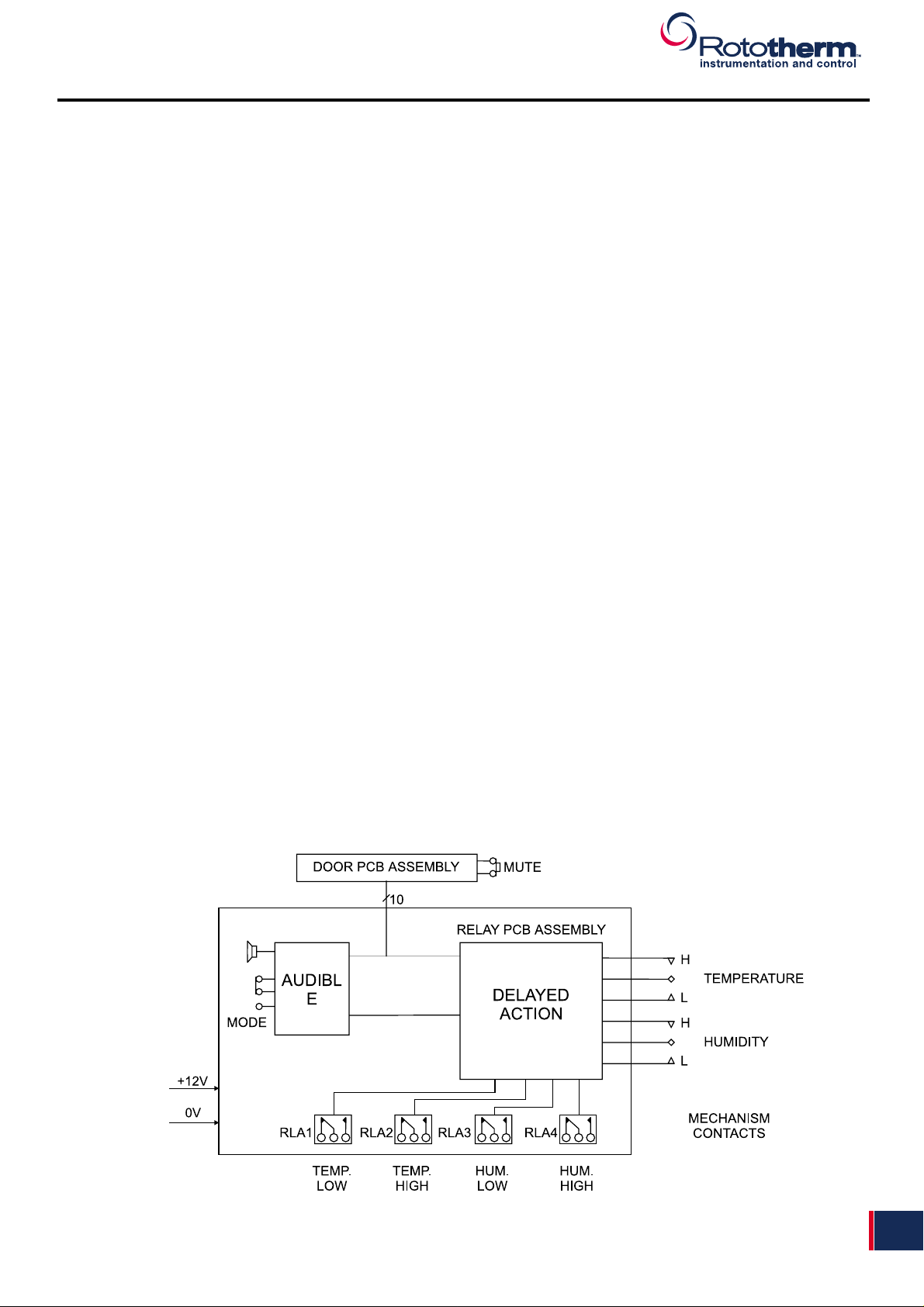
The RTH100 Series range comprises of recorders and recorder controllers as either temperature, humidity or combination instruments. Controllers can be supplied with up to four separate alarm contacts set by reference to a setting pointer adjustable over the
full chart range. Each alarm contact operates and independent output relay providing single pole changeover, voltage free, output
contacts. High and low alarm points for temperature and humidity are indicated by illumination of red LED’s positioned above the
viewing window in the upper part of the recorder door. All control instruments are fitted with an audible alarm indication of set points,
silenced in operation by pressing the switch located
Fig 1. Operation - Control / Alarm Circuit
Page 3

RTH100 Series Temperature & Humidity Recorder
Instruction Manual
Page 2
2
Specifications
Range
Temperature: 0º to 40º or 20º to 100ºF
Humidity: 20 to 100% RH (see notes)
Measuring System
Temperature: Bi-metallic coil
Humidity: Hygroscopic membrane
Accuracy
Temperature: ±1% of the chart range
Humidity: ±2% within the limits 30 to 85% RH and 1º to 40ºC
Chart
Diameter: 240 mm diameter
Drive: Electrical motor
24 hour or 7 day rotation as standard 3 hour, 6 hour, 12 hour and 28 day on application
Outputs and Set Points
Number of set points: Up to 4 set point adjustment by setting pointer against chart graduation
Number of output relays: Up to 4
Relay contacts: Double pole changeover
Switched voltage max.: 30Vdc/277Vac
Switched current max.: 10A
Switched load max.: 150W/1660VA
Insulation, contact to earth: 2kV
Power Supplies
Voltage requirements: 110V or 230V 50/60 Hz
Power requirements: <20VA
Insulation, contact to earth: 2kV
Environmental Data
Storage temperature limits:
Temperature instruments: -10º to +50ºC
Temperature/humidity inst.: 0º to 40ºC
Storage humidity limits
Temperature instruments: 0 to 90%RH
Temperature/humidity inst.: 20 to 85% RH
Casing Glass filled resin case with lockable hinged door with perspex window (polycarbonate to
special order)
Mounting
Ambient sampling Wall or flush panel or portable*
Remote sampling Wall
Note When panel mounting, a suitable air circulation must be provided to the duct intake and the inlet and outlet ports must not be restricted.
* Free standing portable version available (ambient sampling type only)
Weight 6.5 Kg approx.
Sampling Type Total sampling line length is restricted to 1 metre max (20mm OD)
Where the temperature difference between sample air and case exceeds ±5ºC then the sample line must
be thermally insulated
Should the RH go above 85% RH it is possible that water droplets may form on the element. This may
have a temporary or permanent affect on the calibration.
Page 4

RTH100 Series Temperature & Humidity Recorder
Instruction Manual
Page 3
3
Alarm/Control Relays.
In recorder-controller versions of the RTH100 Series two single-pole changeover delayed-action relays are fitted for each pen.
These relays may be used either to activate an alarm should the recorder's pens move above or below the range of normal indication, or to connect the instrument to a closed-loop temperature or humidity control system.
For each pen, one relay is associated with the adjustable low contact of the mechanism (item 8 or 1 1 in figure 6) and a second relay
with the high contact (item 9 or 10). The status of the mechanism contacts is indicated by the light-emitting diodes (LEDs) mounted in the door of the instrument. The relays are designed to be failsafe and are energised when the actual value pen lies within the
contact limits of the desired value pointer (This is the 'normal' or 'non-alarm' condition; the mechanism contacts will be open and the
LEDs extinguished). It should be noted that the normally-open (NO) and normally-closed (NC) labelling, carried on the relay cover
plate and reproduced in figure 3, refers to the relay contact connections with power applied to the instrument and the pens within
their mechanism contact limits.
Each alarm/control relay is rated as follows:Contact arrangement : Single-pole changeover
Switched voltage max. : 30 Vdc / 277 Vac
Switched current max. : 10 A
Switched load max. : 150 W /1660 VA
When switching inductive loads it is recommended that an R-C protection network be wired in parallel with the relay contacts to
reduce arcing.
Audible Alarm.
Closure of the high or low mechanism contact on either pen will cause an audible alarm to sound. This alarm may be silenced in
one of two ways according to the setting of the mode switch which is located on the relay printed circuit board beneath the chart
plate.
Mode 1 : Permanent Silence.
In Mode 1 the alarm will be permanently silenced when the light-emitting diode (LED) built into the mute switch is illuminated.
Pressing the mute push-button will turn the LED on or off. When not silenced, the audible alarm will sound for as long as the pen
remains outside the contact limits.
Mode 2 : Temporary Silence.
In Mode 2 an audible alarm caused by either pen moving outside the contact limits may be silenced temporarily by pressing the
mute push-button. The mute switch LED will be illuminated to acknowledge that the alarm has been silenced. The alarm will only
be silenced while the pen remains outside contact limits: the temporary silence will be cancelled automatically when the pen returns
to within limits and the alarm will sound again should the pen subsequently move outside limits once more.
If an alarm caused by one of the two pens is temporarily silenced, the second pen will still cause the alarm to sound if it too also
moves outside its contact limits. Pressing the mute push button once more will silence the second alarm.
Installation
Ideally the site chosen should be free from dust, corrosive fumes, vibration and extremes of temperature.
Mounting the Controller
The controller may be surface or flush panel mounted.
For surface mounting, remove the screws holding the three brackets at the rear of the case, reverse and refit brackets with there
ends projecting from the edges of the case. The bracket with the keyhole slot must remain at the top of the case.
Drill three holes in the panel (or wall), of the size and at the centres given in Fig. 2 below.
Fit a screw of maximum diameter 6.35 mm (1/4") in the top hole. Locate the instrument on this screw and fit two similar screws
through the other two brackets to secure.
For flush panel mounting, make a cut out to the dimensions given in Fig. 2. Drill three holes and slot two to the cut-out edge as
shown.
Remove the nuts and washers from the studs projecting from behind the case flange, pass the instrument through the cut-out
and refit the washers and nuts to secure the instrument.
Page 5

RTH100 Series Temperature & Humidity Recorder
Instruction Manual
Page 4
4
Fig 2. Outline Dimensions and Fixing Details
Portable Mounting
Surface Mounting
Flush Panel Mounting
All dimensions are in mm
Page 6

RTH100 Series Temperature & Humidity Recorder
Instruction Manual
Page 5
5
Access to Instrument
To open the instrument door press the plunger of the door lock and pull the door forward from the right. As the door is opened the
pen lifter raises the pen ( or pens) away from the chart. Remove the thread that secures the pens to the pen lifter for transit purposes.
To make electrical connections and to set contacts remove the chart plate by loosening the three retaining screws and carefully lift
out the chart plate via the finger hole ( care is necessary to avoid pen lifter interference with pens and control pointers ). Pull the
bottom edge clear of the instrument and lower the chart plate from behind the pens. If the instrument already has a chart fitted this
will need to be removed ( see Fig. 4.).
Electrical Connections
BEFORE MAKING ANY CONNECTIONS TO THE INSTRUMENT ENSURE MAINS SUPPLY CABLE HAS
BEEN ISOLATED FROM THE MAINS SUPPLY
All electrical connections are made to terminal blocks in the lower part of the case behind the chart plate.
Mains Supply and Relay Connections
Insert mains supply cable (isolated) through cable gland in the underside of the case and connect to either the stand alone terminal block for recorders or the power supply board terminal block for controllers. A three core cable switched and fused 5 Amp should
be used. Set the voltage selector switch ( adjacent to the transformer) to the required voltage.
Insert relay connection cables through cable glands and connect to relay board terminals, having first removed the relay cover see
Fig. 3.
RELAY CONNECTING CABLES SHOULD ONLY BE CONNECTED AFTER CONTACT DIFFERENTIAL
SETTINGS HAVE BEEN CARRIED OUT ( See page 6.).
Fig 3. Mains Supply & Relay Connections
Page 7

RTH100 Series Temperature & Humidity Recorder
Instruction Manual
Page 6
6
Fitting a Chart
Release the clamp as shown in Fig. 4. Fit the chart onto the spindle of the clamp and rotate the chart until the pen tip is on the correct time line. Lower the chart clamp and press it firmly to ensure that the locating pips pierce the chart. Place the chart beneath the
outer chart clips.
Fig 4. Fitting a Chart
Inking System
All recorders and recorder controllers are fitted with disposable fibre tipped pens. These pens slide onto the pen arms. The recorder
pen arm is removable from the pen mechanism see Fig. 5. It is advisable to remove the pen arm from the mechanism of recorders
when fitting new pens because of the possibility of undue forces being applied to the mechanism thus causing a possible error shift.
Recorder controller pen arms are fixed to the mechanism and must remain in situ when changing pens.
The under side of the pen cartridge contains a recess which engages with the pen arm. The pen is pushed fully along the arm until
the stop is reached. This operation needs care so as to not bend the pen arm and so cause a pen tension problem.
Fig 5. Replacing Pen Arm from Mechanism
Page 8

RTH100 Series Temperature & Humidity Recorder
Instruction Manual
Page 7
7
Contact Differential
The procedure in the following paragraphs are for a single pen or dual pen instruments.
Refer to Fig. 6. below for mechanism detail.
With the chart plate removed, cut a segment of chart and place on to the chart clamp. Set the desired value pointer (1 or 2) to the
required value by means of the setting knob (3 or 4).
Move the actual value pen (5 or 6) until it just makes contact with the switch arm (7).
Note: The contact point can be determined by observing the LED's in the instrument door
The mains supply needs to be connected and switched on and the insulation spanner supplied must be
used (the mechanism contacts carry 12 volts).
Move the actual value pen (5 or 6) to the required deviation above the desired value pointer (1 or 2) and adjust the high contact (9
or 10) until it just makes contact with the switch arm (7) as indicated by the high alarm LED in the instrument door.
Low contact is set by moving the actual value pen (5 or 6) to the required deviation below the desired value pointer (1 or 2) and
adjusting the low contact screw (8 or 11) until it just makes contact with the switch arm (7) as indicated by the low alarm LED in the
instrument door.
Fig 6. Recorder Mechanism
Page 9

RTH100 Series Temperature & Humidity Recorder
Instruction Manual
Page 8
8
Adjustments
The instrument is calibrated and factory set against traceable standards before despatch. The only adjustment available is zero
adjustment see Fig's. 7 and 8.
Temperature and Humidity accuracy can be checked by the use of Thermometers or Whirling Hygrometers.
Zero Adjustment
If a careful check against a known and steady conditions shows the pen reading to be in error, this can be corrected by means of
the zero nut (Z).
Fig 7. Temperature Arrangement
Fig 8. Humidity Arrangement
Remote and Re-entry
Remote and re-entry models are calibrated under working conditions and are factory set against traceable standards before
despatch. The only adjustment available is zero adjustment see Fig's 7 and 8.
No adjustment should be made to the recorder unless it has been running for a period of at least 3
hours. This period of time ensures that the internal temperature of the recorder case has stabilised and
the true environmental conditions are being recorded.
Maintenance
Keep the instrument clean and treat with care. If the instrument is being used in dusty environments it is advisable to periodically
check if dust and particles are accumulating around the direct linkage arrangement. If there is an accumulation in these areas, it
should be removed with either a low pressure air line or a fine brush.
In the event of heavy contamination of dust it is also advisable to remove the sensing element cover and carefully remove the contamination from the hygroscopic membrane and bimetallic coil. A check on calibration as detailed on page 7 is advisable.
Spare Parts
Description Part Number
Relay Board Assembly - Single Control 29442-04
Relay Board Assembly - Double Control 29251-04
Power Supply Board 29233-04
Pen Pack-Red 28676-11
Pen Pack-Blue 28677-11
Charts Reference number on chart
 Loading...