

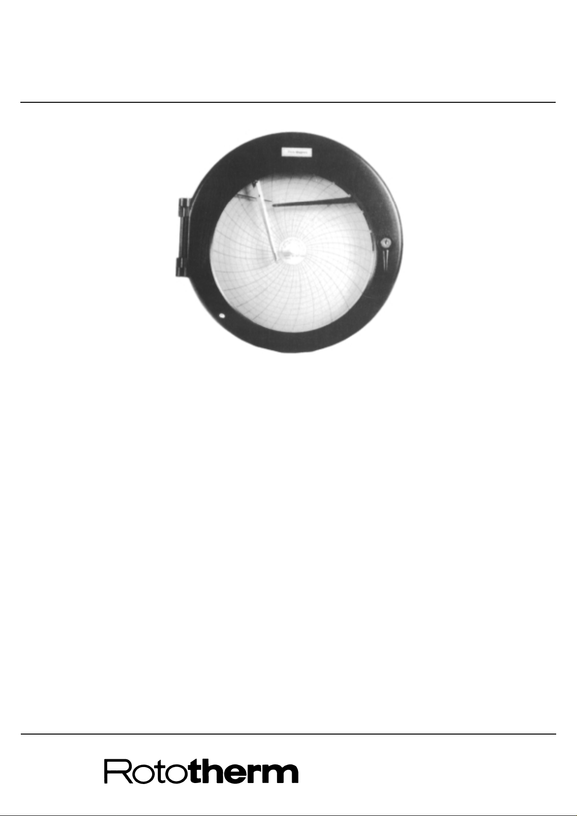
C105 Circular Case Recorder
Operating Instructions
instrumentation and control
The chart drive and control system on this instrument may be operated from a mains voltage supply. The mains must
be switched off before making any mechanical adjustments other than of the set pointers or carrying out any
maintenance or fault finding procedures. When making electrical adjustments observe the warning notes in the text.
INTRODUCTION 2
Identification 2
Specification 3
INSTALLATION 4
Mounting 4
Access to Recorder 5
Process Connections 5
Electrical Connections 5
OPERATION 6
Mechanical Clock 6
Fitting a Chart 6
Set Pointer Adjustment 6
Inking System 6
Zero Adjustment 7
Start-up Check 7
Start-up Procedure 7
Description of Operation 8
Electrical alarm/control system 10
Programme Control 10
MAINTENANCE 11
Cutting a programme cam 11
Pen Adjustment 11
Calibration 11
Servicing 12
Wet and Dry Bulb Water Bath 13
SPECIAL INSTRUCTIONS & DIAGRAMS 14
FAULT FINDING 15
SPARES LIST 15 & 16
Page No. Page No.
CONTENTS
Fig. 1.
2
INTRODUCTION
The C105 series of instruments is designed to measure, record and control process variables such as
temperature, pressure and humidity. A maximum of two measuring systems is provided in each
instrument; a fluid expansion type or bimetallic system is used for temperature recording, a hygroscopic
element or a wet and dry bulb system for humidity and a Bourdon tube or diaphragm for pressure
measurement. The measured values are continuously recorded on a calibrated circular chart which is
rotated at a constant speed by a mechanical or electric clock. Control of the process variable is provided
electrically.
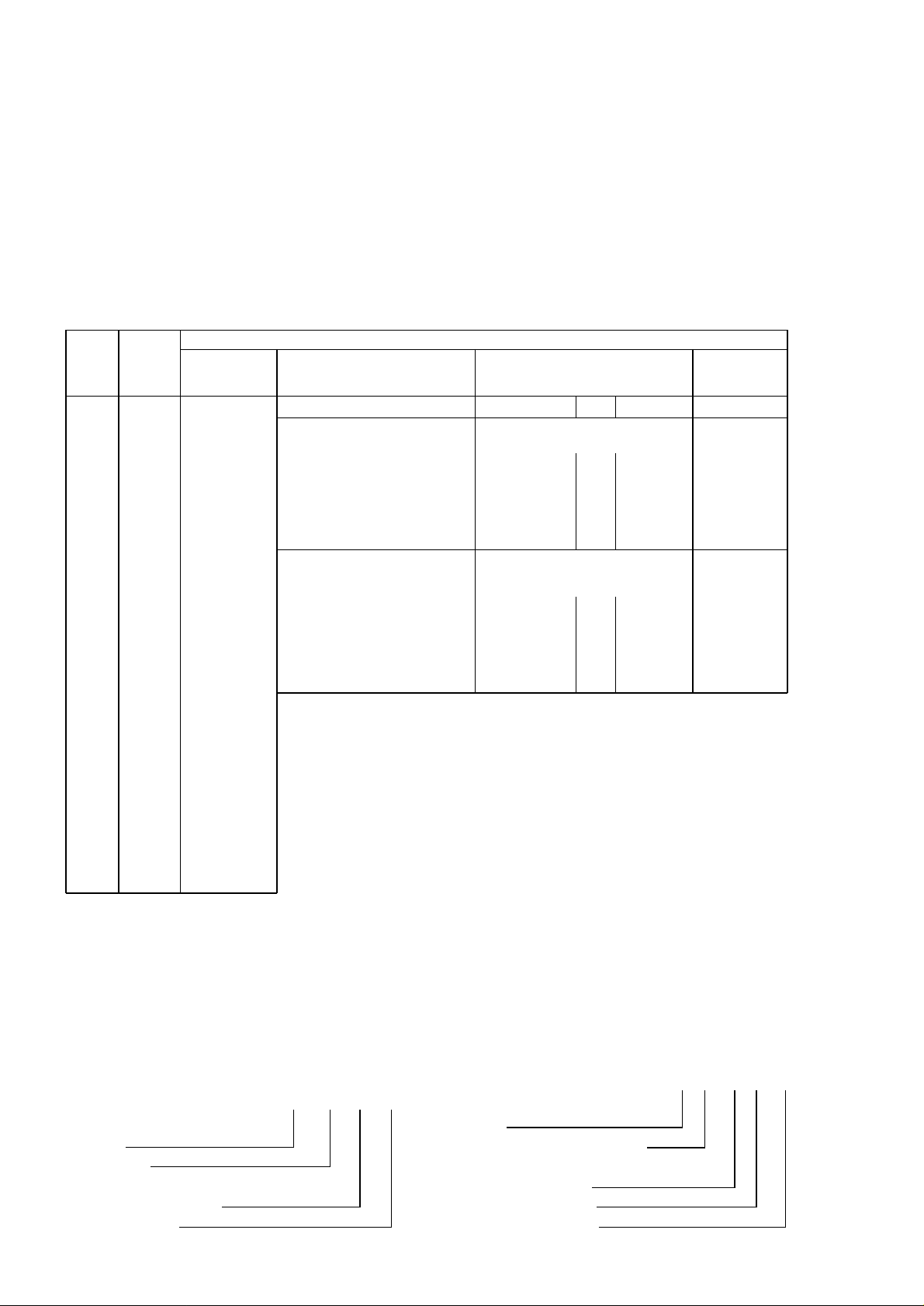
Basic
Type
Number
C10
Recorder
with
105mm
pen
travel
on
circular
chart
5 One
pen
6 Two
pen
1 T emperature
(Fluid
expansion
system)
2 Pressure
(‘C’ Spring–
316 st.steel)
3 Pressure
(Spiral
Bourdon –
phosphor
bronze)
4 Pressure
(Spiral
Bourdon –
321 st.steel)
5 Pressure
Capsule
Stack –
beryllium
copper)
6 Pressure
(Diaphragm
Stack –
beryllium
copper)
7 Relative Humidity
(Goldbeater skin)
– External
9 Pressure
(Coiled Tube –
316 st.steel
No. of
Measuring
Points
Programme
Control Cam
(Single Pen
only)
Measured
Variable
Each Pen
Alarm or Control Mode Set Points
No. 1 No. 2 Nos. 3 & 4
17 Record only – – – – –
Electric Alarm/Control Position of Pen in relation to
with Relay Output Set Point when Relay is energised
00 Two Step Above – None, or any – or C
01 Two Step Below – combination – or C
05 Three Step Below Below applicable –
06 Three Step Above Above to Set Points –
09 High-low Above Below No. 1 & 2 –
03 Double 2 Step Above/Above – – or C
04 Double 2 Step Below/Below – – or C
Contact Action at Set Point
Electric Alarm/Control when Pen moves towards
Contacts only – no Relay outside of Chart
60 Two Step –Contact Mode C Make – – or C
61 Two Step –Contact Mode A Break – None, or any – or C
65 Three Step –Contact Mode AA Break Break combination –
66 Three Step –Contact Mode CC Make Make applicable –
69 High-Low –Contact Mode CA Make Break to Set Points –
63 Double 2 Step –Contact Mode D Make/Make – No. 1 & 2 – or C
64 Double 2 Step –Contact Mode B Break/Break – – or C
Notes:
Code No. is built up thus:
Single Pen C105/1 1 63 C
One Pen
Temperature
Double 2 Step –
Contacts only (no relay)
Programme Cam
Two Pen C106/3 00/1 17
Two Pens
No. 1 Pen – Pressure (Bourdon)
– 2 Step Elec. Alarm
with Relay
No. 2 Pen – Temperature
– Record only
(
(
(

3
Specification
General:
Chart diameter 255mm
Writing width 105mm
Intrinsic error ± 1% span maximum (±2% R.H. for hygroscopic
membrane system)
Operating temperature limits –10
o
to +50oC Except for
Operating humidity limits 0 to 80% R.H. humidity recorders
Zero error due to ambient temp. variations ±0.05% span/
o
C typical
Chart speeds 1 rev every 12 hours, 24 hours or 7 days
Chart drive Synchronous electric motor or mechanical clock
Power supply voltage and frequency 200/250V or 100/120V, 50 or 60Hz
Mounting Wall or panel
Temperature measuring instruments:
Measuring systems Fluid expansion
Maximum length capillary 30m
Minimum span 40
o
C
Maximum span 500
o
C
Span limits – 30
o
C to +600oC
Pressure measuring instruments:
Measuring system Capsule stack, Bourdon tube or coiled tube
Minimum span 0 to 1 bar vacuum or pressure.
Maximum span 1200 bar
Span limits –1 bar to 1200 bar
Connection size Ranges up to 40 bar: a inch B.S.P.) with nut and tail
Ranges over 40 bar: 2 inch B.S.P.) piece for 8mm tube
Humidity measuring instruments:
Measuring systems Sensitive hygroscopic membrane and fluid filled system
for temperature measurement, or wet and dry bulb fluid
expansion systems.
Spans 20 to 100% R.H. (hygroscopic membrane);
0 to 40
o
C (fluid filled systems)
Operating temperature limits 0 to 40
o
C
Operating humidity limits 30 to 85% R.H.
Maximum length of capillary
(wet and dry bulb system) 30m (each bulb)
Electric alarm or control:
Instrument contacts 20mA inductive or 30mA non-inductive load max.
Contact action Make above or below set point as required
Relays Delayed action double pole change-over, 5A, 240V
50Hz non-inductive load, as standard
(Refer to wiring Diagram, p.14).
Relay action Energised above or below set point as required.
Overall dimensions 350mm wide; 137mm deep; 350mm high
(Temp & R.H. 582mm high)
Panel cut-out 318mm diameter
Maximum panel thickness 25mm
Weight 10kg
667788
4
INSTALLATION
Mounting
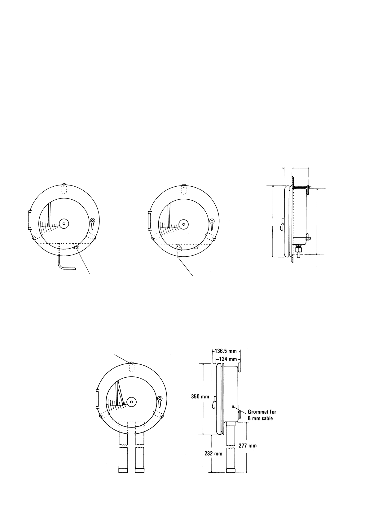
The instrument can be wall or panel mounted using the same fixing brackets. Do not install near any very hot
apparatus, e.g. ovens, steam pipes or flues. Mount the recorder vertically in a position free from vibration and
excessive temperature.
For panel mounting remove the fixing screws and rotate the fixing brackets so that the instrument can be inserted
in the hole in the panel. Return the brackets to their original position and insert the fixing screws. Tighten the
screws until they bear against the back of the panel.
Hygroscopic measuring instruments have external measuring elements requiring a clearance of 240mm below the
case, and must be wall mounted.
Temperature Recorder
Temperature and Relative Humidity Recorder
Wall Mounting
Pressure Recorder
Panel Mounting
41 mm
83 mm
350 mm
Panel
cut-out
dia. 318 mm
Cable gland for
w” conduit
a” or 2” B.S.P. union with nut,
and tailpiece
Three holes at 120º on 340 mm p.c.d.
to take 6.4 mm diam. screws
for wall mounting
Fig. 2.

5
Access to Recorder
To open the door, unlock, and turn the latch anticlockwise. As the door is opened the pen lifter raises the pen (or
pens) away from the chart. Remove the chart (see page 6).
If the instrument is connected to the mains, switch off the mains supply before dismantling further.
For access to the terminal blocks remove the lower plastic plate from behind the chart by undoing the one
retaining screw.
For access to the relays and measuring systems, first remove the chart. Unhook the pens from their mounting
(see Fig. 3.). Remove the three screws from the outside edge of the chart plate. (The pen lifter is secured by one
of these screws and must also be removed). Lower the chart plate carefully. The chart motor is mounted on the
back of the chart plate and if the motor is an electric one it remains connected to the terminal block in the lower
part of the case.
When replacing the chart plate reverse the above procedure. The coil on the pen lifter should be against the side
of the case when the retaining screw is tightened.
Process Connections
To avoid confusion on instruments with more than one measuring system, setting pointers are labelled and
Bourdon tube capillary connections to the instrument are painted with the same colours as the inks used for the
corresponding pens.
Process connections – temperature measuring instruments:
Install the sensing element (bulb) of the instrument in the apparatus where the temperature is to be measured.
The circulation around this element should be good and it should not be too close to any heating or cooling coil or
other controlling medium. Fasten the capillary tubing at frequent intervals to rigid supports avoiding sharp bends
of less than 50mm. radius anywhere along its length. The tubing must not touch or run close to any hot apparatus
and should take the path least subject to temperature variation. If the temperature source is likely to move or
vibrate allow one or two coils of 100mm. diameter of the capillary tube to eliminate stress of the tubing.
If the atmosphere around the capillary tube is likely to be corrosive, paint the tube with anti-corrosive paint and
ensure this is maintained.
Process connections – pressure measuring instruments:
Connect the Bourdon tube sensing element to the measuring point on the apparatus using pressure tubing of the
same or similar material as the Bourdon tube and of sufficient pressure rating. Slope the run of the tubing so that
any condensate is drained away from the instrument and does not affect the accuracy of measurement. For
measurement of steam pressure or other hot vapours, form a condensate trap below the instrument.
Process connections – humidity measuring instruments (wet and dry bulb):
Install the sensing elements (bulbs) where the humidity is to be measured as described for temperature
measuring instruments. The wet bulb (red pen system) is kept moist by a fabric covering, forming a wick which
dips into a constant level water bath. Adistilled water supply tank should be connected to the inlet feed pipe with
a head of between 1 and 6 metres.
It is important to install the bulbs in a position where the air speed is 3.6 metres per second or more. Below this
speed inaccuracies of bulb depression may occur. The air should pass over the bulbs in such a direction that the
water evaporating from the wet bulb does not pass over the dry bulb. The water must be kept clean and free from
impurities. The temperature of the bath and all piping must not fall below 0
o
C. See also page 13.
Electrical Connections
Before making any connections to the instrument switch off the mains supply to be connected.
All electrical connections are made to terminal blocks in the lower part of the case behind the lower section of the
chart plate.
Insert the leads through the cable gland in the underside of the case (see Fig. 2.) and make the connections as
shown on the terminal labels or Wiring Diagram (page 14). The live line should be switched and fused with a 2
amp fuse. If the instrument is mounted on an insulated panel the case should be earthed.

6
OPERATION
Mechanical Clock
To wind the mechanical clock first remove the chart as described below.
This exposes the clock key, which is permanently fitted in the front recess of the clock moulding.
To wind the clock turn the key clockwise. Do not overwind.
Fitting a Chart (Spider Clamp)
Unscrew the milled head on the centre of the clock
spindle until the spider retracts. Remove the chart. Fit
the new chart over the spider head onto the locating
boss. Rotate the chart until the pen tip coincides with the
correct time line and clamp by screwing down the milled
head. On a two-pen instrument the outer (red) pen,
should be set on the correct time line.
Fitting a Chart (Lever Clamp) – Fig 2(a)
Release the clamp as shown. Remove the old chart. Fit
the new chart on the spindle and rotate the chart until
the pen tip is on the correct time line. Lower the chart
clamp and press on it firmly to ensure that the locating
pips pierce the chart.
Set Pointer Adjustment
To set the desired alarm/control point slacken the
clamping knob at the right-hand end of the setting
pointer (Fig. 5), position the pointer on the desired value
and re-tighten the clamp.
Inking System
The pen is tied during transit, but if dislodged it can be
simply reassembled as shown. The pen arm is forked,
one prong being pointed, the other curved. The pointed
prong fits into a conical hole in screw S and curved one
into the V shaped groove V. The pen is held in position
by a spring X and hook Y. On the rear pen the hook Y
faces towards the rear.
The writing system uses fibre pen capsules. Adovetail
on the capsule fits into a slot at the end of the pen arm
and the capsules are easily replaced when the ink is
exhausted. To fit a capsule, pull the pen arm gently clear
of its mountings S and V and unhook it from instrument.
Slide off the used capsule and replace it with a new one
of the appropriate colour. Where there are two
measuring systems, different coloured inks are used to
distinguish the traces. The fibre tip is protected by a
plastic cap, which should be removed by pulling in line
with its length, gripping the end only and gently twisting.
Do not bend. The front pen (red) has a long fibre tip and
the rear pen (green) a short tip.
Place the spring X over the hook Y and gently pull the
pen arm to locate it in its mountings S and V. Take care
not to bend the pen arm.
In some instruments, (supplied to special order only) fibre pen capsules are not used and each pen reservoir
must be filled with ink using the dropper supplied in the ink bottle. Each pen should be cleaned occasionally by
drawing the edge of a piece of stiff paper through it. If it becomes dirty or greasy remove the pen arm and wash
the pen methylated spirits.
Fig. 2(a) Chart Lever Clamp
Fig. 3
Release
Pen arm
Plastic cap
Capsule dovetail
Dovetail slot
Capsule
Pull and
twist
Clamp

7
Zero adjustment
NOTE: After making any zero adjustment to instruments fitted with control or alarm contacts the relay operating
point must be checked and adjusted as described on page 10.
Zero adjustment – temperature recorders and wet and dry bulb humidity instruments:
All instruments are calibrated against a standard thermometer before despatch but should be checked in case of
slight disturbance during transit. Immerse a standard thermometer with the bulb and check the readings. If
adjustment is necessary open the door and rotate the small knurled screw S (in Fig. 3.) to bring the pen to the
correct reading.
Zero adjustment – pressure recorders:
Use a reliable pressure gauge to check the readings and
adjust, if necessary, as for the temperature recorder.
Zero adjustment – temperature and humidity recorders:
Check the temperature reading against a standard mercury-in-
glass thermometer and the humidity reading against a whirling
hygrometer using hygrometric tables to relate humidity to wet
and dry thermometer readings.
Hygrometric tables are compiled by the Meteorological Office
and obtainable from H.M. Stationery Office. Alternatively use
the Psychrometric tables by C.F. Marvin (issued by U.S.
Department of Commerce Weather Bureau) and obtainable
from C.F. Casella & Co. Ltd., Regent House, Brittania Walk,
London N.1.
The zero setting may be adjusted using screw S (Fig. 3). If the
humidity reading requires more correction than that provided
by S, screw J, accessible through the bottom of the guard,
may be adjusted (Fig. 4).
In a bimetallic temperature measuring system the linkages and
zero adjustments are the same as for the hygroscopic
measuring system.
Start-up Check
Before putting the controller into operation make certain it is correctly installed and operational by checking that:
1. The pens operate freely, write cleanly on the chart and can pass each other without touching.
2. Measuring elements are correctly installed.
3. Measuring systems are indicating correctly. If not refer to Zero Adjustment, above.
4. On electrical controllers:
Relays are energised above or below set point as required. If they are not, see Changing the Control Action,
page 10.
5. If a mechanical clock is fitted check that it is wound up (see Mechanical Clock, page 6).
Start-up procedure
Be sure that all steps in the start-up check have been completed.
1. Switch on mains supply to recorder.
2. Position setting pointers on desired alarm/control values.
3. Switch on mains supply to external electric alarm/control systems.
Fig. 4
Linearity adjustment
Ratio arm
Screw J
Hygroscopic
membrane
Pivots

Description of Operation
Temperature recorder (see Fig. 5.)
As the temperature rises, the fluid in the thermometer bulb expands and partially uncoils the spiral Bourdon tube
fitted inside the instrument. This movement is transferred by a mechanical linkage to the pen arm which records
the temperature on a calibrated chart.
Pressure recorder
On medium and high pressure ranges an increase in pressure partially uncoils a Bourdon tube fitted inside the
instrument. This movement is transferred by a mechanical linkage to the pen arm which records the pressure on a
calibrated chart.
A capsule stack or diaphragm system is fitted for low pressure ranges and the expansion of the system resulting
from an increase in pressure is transferred by a mechanical linkage to the pen arm.
8
Fig. 5
Bourdon tube
Set-up spring
Linearity adjustment
Ratio arm pivot
Control unit
Drive link
striker pin
Coarse zero adjustment
Compensator
Setting pointers
Control arm
Terminal block
Relays
Control unit
fixing screws
Setting pointer
clamp
9
Temperature and humidity recorder (see Fig. 4)
The air circulates around a strip of animal tissue (Goldbeater skin) the length of which varies with the relative
humidity. The membrane is mounted under light spring tension and is connected by means of a bell crank lever
and linkage to a pen arm which records the humidity on a calibrated chart. Temperature is measured by a fluid
filled system which is mounted to the left of the humidity element and mechanically linked to a second pen arm.
Humidity recorder – wet and dry bulb
The relative humidity can be obtained from the temperatures measured by the wet and dry bulb thermometer
using hygrometric or psychrometric tables.
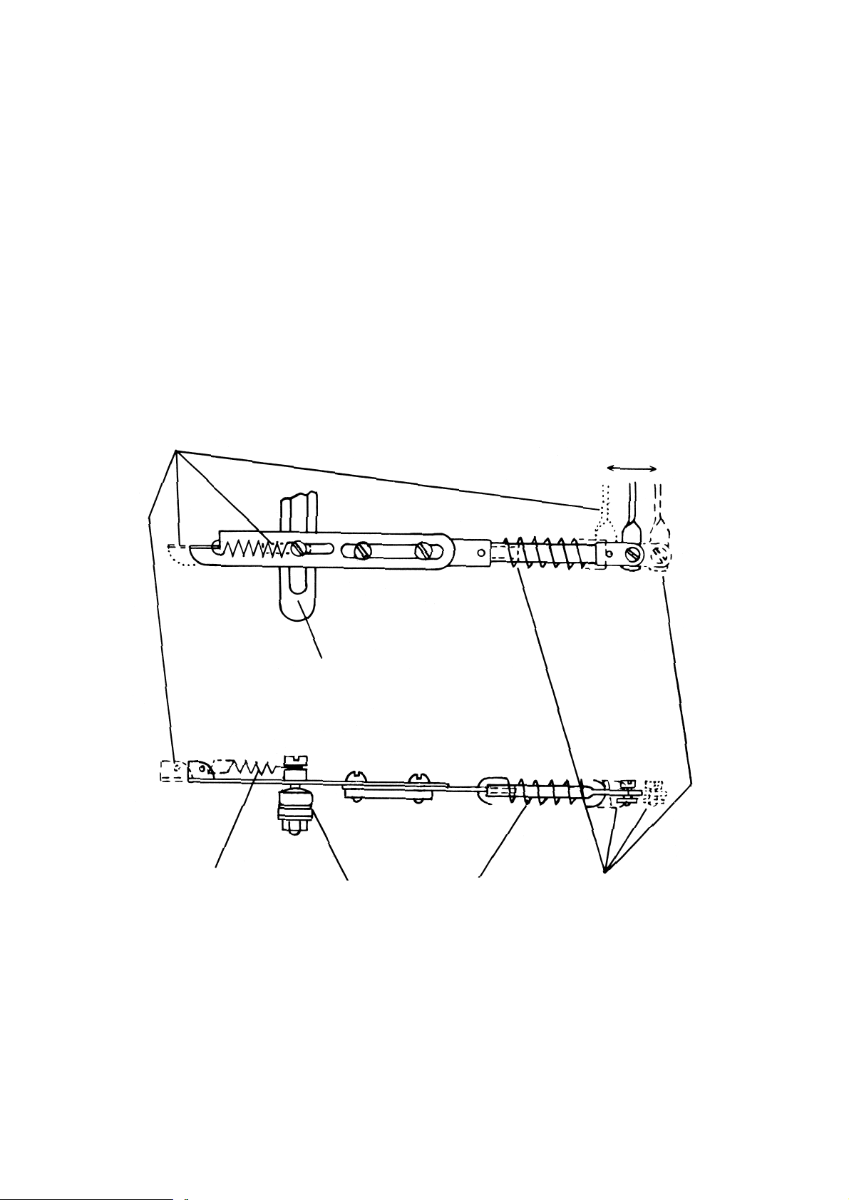
Set up and Overload Protection Springs
To protect the pen mechanics if the measured variable goes significantly outside the span of the instrument the
connecting link may incorporate “set up” and/or “overload” springs (see Fig. 6.).
The set up spring (also shown in Fig. 5.) is used if the measured variable is liable to go significantly below the
chart zero reading, e.g. on a temperature recorder calibrated 100–600
o
C where the measuring element is subject
to normal ambient temperatures during transit. Under these conditions the movement of the Bourdon tube
compensator extends the spring allowing the pen mechanism to rest against the zero stop.
The overload spring is used if the measured variable is liable to go significantly above the maximum chart
reading. Under these conditions the movement of the Bourdon tube compensator extends the spring allowing the
pen mechanism to rest against the top point stop.
Fig. 6
Overload action
Movement of Bourdon Tube compensator
Overload spring
Ratio arm pivot
Set up spring
Set up action

Electrical alarm/control system
Each relay is switched by a contact mounted on an arm linked to the setting pointer which makes or breaks with a
contact attached to the recording pen linkage when the pen reaches the set point (see Fig. 5.). The striker is fixed
relative to the pen arm and a spring loaded contact is fitted to the setting pointer linkage. One set of changeover
contacts is available for external connection for each set point. The contacts are usually labelled “normally closed”
(NC), “common” (C) and “normally open”
(NO) where normally means that no current
is flowing through the relay coil. Refer to
page 14 for any special wiring information.
On wet and dry bulb humidity controllers in
addition to standard control contacts for the
dry temperature a contact may be fitted on
the dry bulb pen linkage so that the wet
bulb depression may be controlled.
Alarm systems should have an independent
power supply to safeguard alarm operation
in the event of mains failure.
Adjusting the relay operating point
If the measured value indication is correct and the relay operates at a value other than that shown by the setting
pointer, the error may be corrected as follows. Move the setting pointer to the indicated value. Switch off the
electrical supply to the recorder and remove the chart, pens and upper chart plate. Slacken the two nylon screws
on the control unit (see Figs. 5 and 7) and slide it along the control arm until the sprung contact just touches the
fixed contact. Re-tighten the screws and replace the chart plate etc. Check the relay now operates at the desired
set point.
Changing the Control Action
Switch off the electrical supply to the recorder and remove the chart, pens and upper chart plate.
To change the relay action from energised below set point (E.B.) to energised above set point (E.A.) or vice-versa
the control unit incorporating the spring loaded contact should be unscrewed from the control arm and a unit with
the contact spring loaded in the reverse direction fitted in its place (see Fig. 7). Adjust the relay operating point as
described above. Tighten the screws and replace the chart plate etc.
Programme Control
Programming is provided by a shaped transparent cam
driven by the chart motor and linked by a cam follower
to a control unit inside the instrument case. The control
unit continually operates external regulating equipment
in accordance with the configuration of the cam. The
measuring system monitors and records the process
variable as in the basic C105 instrument.
The programming cam is mounted over the chart directly
on to the chart drive shaft. The cam follower is a pivoted
arm with a roller lightly sprung against the edge of the
cam at one end and a linkage to the internal control unit
at the other. The cam follower is deflected as the cam
rotates and actuates the electrical control unit. All cams
are interchangeable.
10
Fig. 7. Electrical Control Contacts
Fig. 8
Sprung contact
E.A.
E.B.
Striker pin
Slots for fixing screws
Part no. 15321–80
Cam follower
Programme cam
Cam clamp nut
Chart
Part no. 15321–79

11
MAINTENANCE
Cutting a programme cam
The required programme should be drawn on to a spare recorder chart and transferred using carbon paper or a
similar method to the paper covering on the cam blank. Mark on this trace significant points of the programme
where the process state is important. Mark drilling centres on the radii of these programme points exactly 3mm
out from the points. Drill through with a 6mm drill. Join up the programme points using a saw, and smooth off the
profile between the points.
A cam cut in this way will only provide a programme which is an approximation to the requirement owing to
variations in the distance between the cam-follower and the pen at different positions on the chart. If required,
precise programme cams can be supplied to customers’ specifications.
Fitting a new pen arm
Refer to the SPARES LIST, page 15 for the part numbers of the two pen arms. Make sure the correct replacement
arm (front or rear pen) is obtained. Follow the fitting instructions outlined under Inking System, page 6.
After fitting a new arm check the pen indication on the chart near the zero end of the range. See Zero Adjustment,
page 7.
Pen Adjustment
The pen lifter must be below the arm before the clock is
started. If the pen is bent, the effective length of the pen
arm will be altered so that the pen will not record the
correct time at all temperatures. If when the chart is
stationary the time increases as the pen moves towards
the outside of the chart, the pen arm is too long, and
vice versa, see Fig. 9. The error can be corrected by
careful straightening of the pen or by bowing the pen
arm slightly. Adjust the pressure if necessary by bending
the hook Y in Fig. 3.
Instruments with more than one pen are adjusted in the
same way as those with only one. Each pen is adjusted
independently. The mounting for the pen arm closest to
the chart (the green pen) is reversed and the fibre tip nib
is shorter so that each pen can move freely across the
other’s path. Only the red pen will indicate the correct
time; the green pen being set to record 4mm in advance
of the red.
Calibration – Temperature or Pressure System; Wet and Dry Bulb Relative Humidity System
Switch off the electrical supply to the recorder.
Make sure all pivots and linkages are free moving and adjust as follows:
Allow recorder to stabilise with measuring element in a low temperature (or pressure) just above scale
minimum. Pen should record within ±1% of span of correct value. If necessary adjust zero screw S, Fig. 3.
If pen is significantly out of line with cockpiece, i.e. more than about 5 angular degrees, adjust screw S to
line up pen with cockpiece. Loosen the coarse zero adjustment screw holding the serrated compensator
carrier, Fig. 5. and adjust pen to record true value, making a fine adjustment on screw S after the coarse
zero adjustment screw has been re-tightened.
Allow the recorder to stabilise with measuring element in high temperature (or pressure) just under scale
maximum. Pen should record within ±1% of span of correct value. If not, adjust by moving the link
connecting the compensator arm to the ratio arm on the cockpiece, see Fig. 5. In order to move the link,
loosen the nut at the back of the ratio arm pivot. Raising the pivot will increase the pen movement and
lowering the pivot will reduce the movement. Re-tighten after adjustment.
Repeat steps 1 and 2 until no further adjustment is necessary.
1.
2.
3.
Fig. 9
Decrease length
Red pen arm too long
Red pen trace correct
Green pen trace correct
Red pen arm too short
Length of bow
Increase length

12
Calibration – Relative Humidity System (hygroscopic membrane)
Switch off the electrical supply to the recorder.
During manufacture the measuring element is calibrated in atmospheres of known equivalent relative humidity.
These atmospheres are generated by specific salt solutions at constant temperature in apparatus which is unlikely
to be available to the average instrument user.
Calibration checks can be made without salt solution by using a Whirling Hygrometer and comparing the pen
record with figures obtained from psychrometric tables (see page 7) in various ambient relative humidities, taking
care to allow the recorder time to stabilise at each reading.
Make sure all pivots and linkages are free moving and adjust as follows:
Allow the recorder to stabilise with the measuring element in a low ambient R.H. Pen should record within
±2% R.H. of correct value. If not, adjust zero screw J Fig. 4, in the mounting of the humidity element.
Allow the recorder to stabilise with the measuring element in a high ambient R.H. Pen should record within
±2% R.H. of correct value. If not, adjust by moving the position of the link pivot on the cockpiece ratio arm,
Fig. 4. In order to move the link loosen the nut at the back of the pivot. Raising the pivot will increase the
pen movement and lowering the pivot will reduce the movement. Re-tighten after adjustment.
Repeat steps 1 and 2 until pen records within ±2% of true R.H. at both positions on chart.
Linearity Adjustments to the measuring systems
Linearity adjustments are only likely to be needed if a measuring element has been replaced. Switch off the
electrical supply to the recorder. Follow the appropriate calibration procedure making an additional calibration
check at approximately centre span after the instrument has been adjusted to record correctly at high and low
readings. If necessary, slightly adjust the length of the connecting link (see Figs. 4 and 5). To gain access to the
connecting link remove the chart, pens and upper chart plate as described under Access to Recorder. After
adjusting the length of the link replace the chart plate, etc. recalibrate at high and low readings and then repeat
the centre span calibration check. Continue to make adjustments in this order until the record at all three points is
within specification.
Servicing – General
Every six months lubricate metal bearings using a good quality molybdenised clock oil, such as Moebius 8040/35
clock oil. Do not use this lubricant on any nylon parts. Wipe off any excess lubricant with a clean lint free cloth.
Oiling the mechanical clock
After a long period of operation the clock should be oiled. The complete clock can be detached by unscrewing the
three fixing screws when the chart plate is removed. Use a high grade of clock oil. (This operation should only be
carried out by a suitably experienced person).
1.
2.
3.

13
Wet and Dry Bulb Water Bath
The wick should be changed frequently, the period between changes depending on the surrounding atmosphere.
In wood drying kilns, etc., the wick should be renewed once a week but in clean atmospheres, e.g. offices, it can
be left as long as three weeks. The water must be kept clean and free from impurities.
Fig. 10. Wet and Dry Bulb Water Bath
298.5 mm
Bulb clamp
Dry bulb
Wet bulb
with wick covering
Mounting holes
13.5 mm dia.
127 mm
130 mm
A.
B.
Water bath
Inlet union
Note: Water supply maximum pressure 6 metre head.
231.5 mm
Overflow union
Optimum air flow direction
For capillary entry from the
right mount clamp Ausing
holes B

14
SPECIAL INSTRUCTIONS & DIAGRAMS

15
FAULT FINDING
Recorder pen is inaccurate or gives no indication
1. Measuring element broken; capillary plugged or broken on temperature recorder.
Check elements or capillary and replace as necessary.
2. Disconnected linkage in recorder.
Re-connect or repair as necessary.
3. Recorder out of calibration, measuring element not damaged.
Check and calibrate if necessary, pages 11 and 12.
No record on chart
1. Pen not inking.
Fit new pen capsule, page 6.
2. Chart drive motor stopped.
Rewind, page 6. Replace if broken.
3. Chart clamp broken.
Replace by new assembly.
Poor Control – Electrical
1. Faulty relay.
Replace relay.
2. Friction in measuring system.
Correct action of measuring system.
3. Lack of electrical power in circuit being controlled.
Increase power rating of control equipment.
4. Power in circuit being controlled too high.
Decrease power rating of control equipment.
SPARES LIST
Description Part Number Reference
Chart Quote the number on the chart
supplied or duration and range. Fig. 1
Chart clamp assembly (not programme controllers) 15321/608 Fig. 2(a)
Chart drive motor – electrical (assembled on moulding) Quote chart speed voltage and mains
frequency .
Chart drive motor – mechanical Quote chart speed and specify
“mechanical”.
Circlip – setting pointer spindle 600353
Electrical Control with spring contact on the Control Arm:
Spring contact assembly-relay energized below set point 15321 / 79 (min. type A) Fig. 7
Spring contact assembly-relay energized above set point 15321 / 80 (max. type C) Fig. 7
Striker contact pin 19 s.w.g. silver wire Figs. 5 & 7
Hinge 15 / 240 Fig. 1
Hinge – pin 15 / 243
Hinge – screw 15 / 211
Hinge – spring 15 / 220
Key for lock FA558
Lock with spring washer and catch 22656 / 142 Fig. 1
Pen arm – green (rear position) 15321 / 328 (stamped 8 on pen arm) Figs. 1 & 3
Pen arm – red (front position) 15321 / 327 (stamped 7 on pen arm) Figs. 1 & 3
Pen capsule – green P105M/0302 (pack of 5) Fig. 3
Pen capsule – red P105M/0301 (pack of 5) Fig. 3
Pen lifter 15 / 277

16
SPARES LIST (continued)
Description Part Number Reference
Pressure Recorders:
Tailpiece St/St 2” BSP 22251 / 9
Tailpiece St/St a” BSP 17600 / 01
Tailpiece Brass 2” BSP 22251 / 22
Tailpiece Brass a” BSP 16992 / 51
Nut St/St 2” BSP 22251 / 10 Fig. 2
Nut St/St a” BSP 17599 / 01
Nut Brass 2” BSP 22251 / 20
Nut St/St a” BSP 16692 / 01
Fibre washer 2” BSP 22 / 745
Fibre washer a” BSP 22 / 746
Programme Controllers:
Chart carrier 17271 / 26
Chart clamp nut 17271 / 27
Cam clamp nut 17271 / 6 Fig. 8
Cam blank 17271 / 29
Relay (electrical) – 5 amp 87294
3 amp 600492
Setting pointer clamp nut 15321 / 245
Stud – panel mounting 100013 Fig. 2
Temperature and Humidity Recorders:
Element guard 22 / 401
Wick for Wet & Dry Bulb Water Bath 100016 Fig. 10
Window glass 15 / 204
Window perspex 15 / 204C
Zero screw ‘S’ 15 / 228 Fig. 3
Made Up kits:
Relay type 2400 (Part No. 600169) is no longer available as a spare part and is
replaced by one of the following relay kits.
Single relay replacement:
(200/250V, 50 or 60 Hz supply) 15321 / 542 / 1
(100/120V, 50 or 60 Hz supply) 15321 / 542 / 2 Refer to
Double relay replacement: Service Aid
(200/250V, 50 or 60 hz supply) 15321 / 543 / 1 No. 15321 / 545
(100/120V, 50 or 60 Hz supply) 15321 / 543 / 2
For information on other Spare Parts or Kits contact British Rototherm.
678
6644774488
6447448
We reserve the right to amend specification without notice
© The British Rototherm Company Limited 1990.
The British Rototherm Company Limited
Margam, Port Talbot, West Glamorgan U.K. SA13 2PW
Telephone: (01656) 740551
Fax: (01656) 745915
E-Mail: rototherm@rototherm.co.uk
Distributor
HP • (01656) 788038
15321-524/1
R. 0390
 Loading...