

rotork YT-3700, YT-3750 Product Manual
SMART POSITIONER PRODUCT MANUAL
YT-3700 / 3750
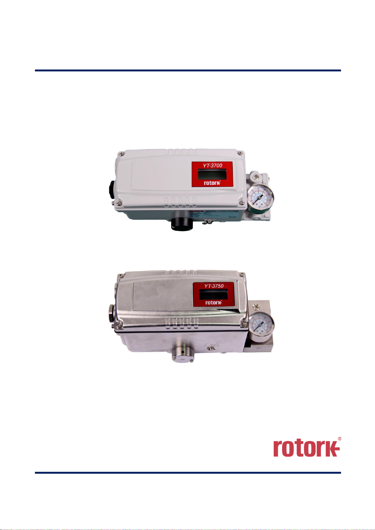
YT-3700
YT-3750
Rotork YTC Limited
VERSION 1.03

Smart Positioner
YT-3700 / 3750 Product Manual
Ver. 1.03 2
Contents
1 Introduction .................................................................................................................................................5
1.1 General Information for the users .........................................................................................................5
1.2 Manufacturer Warranty .........................................................................................................................5
1.3 Explosion Proof Warning (Only for Intrinsic safety type positioners) ....................................................6
2 Product Description ...................................................................................................................................7
2.1 General .................................................................................................................................................7
2.2 Main Features and Functions ...............................................................................................................7
2.3 Label Description ..................................................................................................................................8
2.4 Product Code ..................................................................................................................................... 13
2.5 Product Specification ......................................................................................................................... 14
2.6 Specification of Digital In, Digital out ................................................................................................. 15
2.7 Certifications ...................................................................................................................................... 16
2.8 Parts and Assembly ........................................................................................................................... 18
2.9 Product Dimension ............................................................................................................................ 20
2.9.1 YT-3700 ......................................................................................................................................... 20
2.9.2 YT-3750 ......................................................................................................................................... 20
3 Installation ................................................................................................................................................ 21
3.1 Safety ................................................................................................................................................. 21
3.2 Tools for installation ........................................................................................................................... 21
3.3 Linear positioner Installation .............................................................................................................. 22
3.3.1 Linear positioner Installation of Standard lever type...................................................................... 22
3.3.2 Safety ............................................................................................................................................. 22
3.3.3 Standard lever type positioner Installation Steps .......................................................................... 23
3.4 Rotary positioner Installation ............................................................................................................. 26
3.4.1 YT-3700R / 3750R Components ................................................................................................... 26
3.4.2 Rotary Bracket Information ............................................................................................................ 27
3.4.3 Rotary positioner Installation Steps ............................................................................................... 28
4 Connection - Air ....................................................................................................................................... 29
4.1 Safety ................................................................................................................................................. 29
4.2 Supply Pressure Condition ................................................................................................................ 29
4.3 Piping Condition ................................................................................................................................. 29
4.4 Connection – Piping with actuator ..................................................................................................... 30
4.4.1 Single acting actuator .................................................................................................................... 30
4.4.2 Double acting actuator ................................................................................................................... 30
5 Connection – Power ................................................................................................................................ 31
5.1 Safety ................................................................................................................................................. 31
5.2 Connection ......................................................................................................................................... 32
5.2.1 Standard Terminals ....................................................................................................................... 32
5.2.2 Terminals with micro-limit switch option ........................................................................................ 34

Smart Positioner
YT-3700 / 3750 Product Manual
Ver. 1.03 3
5.2.3 Terminals with proximity Limit Switch option ................................................................................. 35
5.3 Ground ............................................................................................................................................... 35
6 Adjustments ............................................................................................................................................. 36
6.1 Limit Switch Adjustment ..................................................................................................................... 36
6.2 A/M switch adjustment ....................................................................................................................... 37
6.3 Orifice Installment .............................................................................................................................. 38
6.3.1 Plate type Orifice Installment ......................................................................................................... 38
7 Optional Sub-PCB Installment ................................................................................................................ 39
7.1 Installation steps ................................................................................................................................ 39
8 Auto Calibration and PCB Operation ..................................................................................................... 41
8.1 Warning .............................................................................................................................................. 41
8.2 LCD display and buttons .................................................................................................................... 41
8.2.1 LCD display and symbols .............................................................................................................. 41
8.2.2 Button and function ........................................................................................................................ 42
8.3 Menu levels ........................................................................................................................................ 43
8.4 RUN Mode Monitor ............................................................................................................................ 44
8.5 Configuration and Operation .............................................................................................................. 45
8.6 Calibration (CALIb) ............................................................................................................................ 49
8.6.1 Acting Type (SINGLE / dOUBLE) .................................................................................................. 49
8.6.2 Auto Calibration 1 (AUTO 1) .......................................................................................................... 50
8.6.3 Auto Calibration 2 (AUTO 2) .......................................................................................................... 50
8.6.4 Travel Zero (TVL ZERO) and Travel end (TVL ENd) .................................................................... 51
8.7 Manual Operation (MAN OPER)........................................................................................................ 52
8.7.1 Manual Operation by Set position (MAN SP) ................................................................................ 52
8.7.2 Manual Operation by MV (MAN MV) ............................................................................................. 53
8.8 Control Parameters (CTL PARM) ...................................................................................................... 54
8.8.1 Dead Band (dEAdbANd) ................................................................................................................ 54
8.8.2 Forward P parameter (KP UP) and reverse P parameter (KP dN) ................................................ 55
8.8.3 Forward Integral time parameter (TI UP) and reverse Integral time parameter (TI dN) ................ 55
8.8.4 Forward D parameter (Kd UP) and reverse D parameter (Kd dN) ................................................ 56
8.8.5 Auto Dead band Mode (AUTO db) ................................................................................................ 56
8.8.6 Performance Mode (PER) ............................................................................................................. 57
8.9 Input Configuration(IN CFG) .............................................................................................................. 58
8.9.1 Signal Direction (SIG NORM / REVS) ........................................................................................... 58
8.9.2 Split Range Mode (SPLIT) ............................................................................................................. 59
8.9.3 Custom Split Range Zero (CST ZERO) ......................................................................................... 59
8.9.4 Custom Split Range End (CST ENd) ............................................................................................. 60
8.9.5 Valve flow Characterization Curves (CHAR) ................................................................................. 60
8.9.6 User Set Characterization 5 Points (U5) ....................................................................................... 61
8.9.7 User Set Characterization 21 Points (U21) ................................................................................... 62

Smart Positioner
YT-3700 / 3750 Product Manual
Ver. 1.03 4
8.9.8 Tight Shut Open (TSHUT OP) ....................................................................................................... 63
8.9.9 Tight Shut Close (TSHUT CL) ....................................................................................................... 64
8.9.10 Target Position Ramp Up Rate (RAMP UP) and Target Position Ramp Down Rate (RAMP dN)
65
8.9.11 Digital Input Function (dIF) ........................................................................................................ 67
8.9.12 Digital Input Logic (dI LOGIC) .................................................................................................... 67
8.10 Output Configuration (OUT CFG) ...................................................................................................... 68
8.10.1 Position Transmitter Direction (PTM NORM / REVS) ................................................................ 68
8.10.2 Position Transmitter Zero / End (PTM ZERO / ENd) ................................................................. 69
8.10.3 HART Feedback Direction (HT NORM / REVS) ........................................................................ 70
8.10.4 Back Calculation (bACKCAL oFF / on) ...................................................................................... 71
8.10.5 Digital Output Function (dOF) .................................................................................................... 72
8.10.6 Digital Output Logic (dO LOGIC HI / Lo) ................................................................................... 73
8.10.7 Analog Output Function (AOF) .................................................................................................. 74
8.10.8 Analog Output Logic (AO LOGIC Lo / HI) .................................................................................. 75
8.11 Device Configuration (dEV CFG)....................................................................................................... 76
8.11.1 Action Setting (ACT) .................................................................................................................. 76
8.11.2 Linear Interpolation (ITP oFF / on)............................................................................................. 77
8.11.3 Lock of Parameters (Write Protect, W UNLOCK / LOCK) ......................................................... 77
8.11.4 Actual Position View Mode (View Mode, VI NORM / REVS) .................................................... 78
8.11.5 Polling address setting (POL AddR) .......................................................................................... 78
8.11.6 Factory Reset (dEFAULT oFF / on) ........................................................................................... 79
8.11.7 Positioner Self-Test (SELFTEST) .............................................................................................. 80
8.12 Diagnosis Mode (dIAGNd) ................................................................................................................. 81
8.12.1 Default Alarm Settings ............................................................................................................... 81
8.12.2 Process Status (PS) .................................................................................................................. 83
8.12.3 Device Status (dS) ..................................................................................................................... 84
8.12.4 View Monitoring Counts (VI CNTS) ........................................................................................... 86
8.12.5 Diagnostic Limit Configuration (LIMT CFG) ............................................................................... 87
8.12.6 Reset Alarm Status (RST ALRM oFF / on) ................................................................................ 88
8.12.7 View Event Log (EVT LOG) ....................................................................................................... 89
8.12.8 Partial Stroke Test Record (View PST Result Record, PST RSLT) .......................................... 90
8.12.9 PST Configuration (PST CFG) .................................................................................................. 91
8.12.10 Run PST (PST NOW) ................................................................................................................ 92
8.12.11 Periodic PST Test (PST Schedule, PST SCHd oFF / on) ......................................................... 93
8.13 Position information (INFO) ............................................................................................................... 94
8.14 Status and Alarm Code ...................................................................................................................... 96
9 Main Software Map .................................................................................................................................. 99

Smart Positioner
YT-3700 / 3750 Product Manual
Ver. 1.03 5
1 Introduction
1.1 General Information for the users
Thank you for purchasing Rotork YTC Limited products. Each product has been fully inspected after
its production to offer you the highest quality and reliable performance. Please read the product
manual carefully prior to installing and commissioning the product.
➢ Installation, commissioning, and maintenance of the product may only be performed by trained
specialist personnel who have been authorized by the plant operator accordingly.
➢ The manual should be provided to the end-user.
➢ Factory Mutual approved Intrinsically Safe and Non-Incendive units must be Installed Per
drwg SKC_XXXXX_XXXXXX.pdf
➢ CSA approved Intrinsically Safe and Non-Incendive units must be Installed Per drwg SKC-
XXXX.pdf
➢ The manual can be altered or revised without any prior notice. Any changes in product’s
specification, design, and/or any components may not be printed immediately but until the
following revision of the manual.
➢ When the manual refers to “Valve Zero / Zero” means the final valve position upon pneumatic
pressure has been fully exhausted from positioner’s OUT1 port. For example, the valve zero
position may differ between linear direct and reverse actions. (DA/RA)
➢ The manual should not be duplicated or reproduced for any purpose without prior approval from
Rotork YTC Limited, Gimpo-si, South Korea.
➢ In case of any other problems that are not stated in this manual, please make immediate contact
to Rotork YTC Limited.
➢ Positioner is an accessory of the control valve, so please make sure to read the applicable
instruction manual of the control valve prior to installation and operation.
1.2 Manufacturer Warranty
➢ For the safety, it is important to follow the instructions in the manual. Manufacturer will not be
responsible for any damages caused by user’s negligence.
➢ Any modifications or repairs to the product may only be performed if expressed in this manual.
Injuries and physical damages caused by customer’s modifying or repairing the product without
a prior consultation with Rotork YTC Limited will not be compensated. If any alterations or
modifications are necessary, please contact Rotork YTC Limited directly.
➢ The warranty period of the product is (18) months from the date of shipment unless stated
otherwise. Date of shipment can be checked by providing the LOT NO. or SERIAL NO. to us.
➢ Manufacturer warranty will not cover products that have been subjected to abuse, accidents,
alterations, modifications, tampering, negligence, misuse, faulty installation, lack of reasonable
care, repair or service in any way that is not contemplated in the documentation for the product,
or if the model or serial number has been altered, tampered with, defaced or removed; damages

Smart Positioner
YT-3700 / 3750 Product Manual
Ver. 1.03 6
that occurs in shipment, due to act of God, failure due to power surge, or cosmetic damage.
Improper or incorrectly performed maintenance will void this limited warranty.
➢ For detailed warranty information, please contact the corresponding local Rotork YTC Limited
office or main office in South Korea.
1.3 Explosion Proof Warning (Only for Intrinsic safety type positioners)
Please ensure the unit is being used and installed in conformity with local, regional, and national
explosion proof within the proper safety barrier environment.
➢ Refer to “2.7 Certifications”
➢ Explosion proof type of cables and gaskets should be used, when explosion gases are present
at the installation site.
➢ Positioner has 2 ports for power connection. Explosion proof type wires and packing should be
used. Blind plug is required when any port is not being used.
➢ Ring terminal with surface area of more than 1.25mm2 with M4 spring washer should be used to
connect the power.
➢ For external ground terminal, ring terminal with surface area of more than 5.5mm2 should be
used.
➢ Wiring in these applications shall utilize appropriate methods for Class I, Division 2 / Zone 2
➢ Substitution of components may impair intrinsic safety.
➢ Substitution of components may impair suitability for Class I, Division 2.
➢ EXPLOSION HAZARD. Do not connect or disconnect wiring unless all sources of power have
been removed or the area is known to be non-hazardous.
(French) RISQUE D'EXPLOSION. Ne pas raccorder ou débrancher le câblage à moins Toutes
les sources d'énergie ont été enlevées ou la zone est connue pour être non dangereux.
➢ The enclosure of model YT-3700 contains aluminum, which is considered to constitute a
potential risk of ignition when subjected to impact or friction. Care must be used during
installation in locating this equipment to prevent impact or friction
➢ Some of the enclosure parts are made of non-metallic materials. To prevent the risk of
Electrostatic sparking, clean the enclosure only with a damp cloth.
➢ The product must be installed in such a manner as to minimize the risk of impact or friction with
other metal surfaces.
➢ For Intrinsically Safe installations, the product must be connected to suitably rated intrinsically
safe equipment, and must be installed in accordance with applicable intrinsically safe installation
standards.

Smart Positioner
YT-3700 / 3750 Product Manual
Ver. 1.03 7
2 Product Description
2.1 General
YT-3700 / 3750 series Smart Valve Positioner accurately controls valve stroke in response to an input
signal of 4~20mA from the controller. Built-in micro-processor optimizes the positioner’s performance
and provides unique functions such as Auto-Calibration, PID Control, and HART Protocol
Communications.
2.2 Main Features and Functions
➢ LCD display enables users to monitor the positioner status.
➢ User will easily understand the method of using 4 buttons because it work same in all versions of
firmware interfaces.
➢ When unexpected situation like momentary blackout happens, our positioner boot-time only take
0.5 second and this can minimize the travel of valve which consequentially increase the safety of
system.
➢ Positioner operates normally even there are sudden changes in supply pressure and / or high
vibration environment.
➢ The method of Auto Calibration is very simple.
➢ As an advantage of having very low air consumption, It could greatly reduce operating costs in
large-scale plants.
➢ It is compatible with most of controllers.
➢ Orifices can be installed even in the field to minimize the hunting occurrence and optimize
operating conditions.
➢ Various information about positioner can be processed by HART communication.
➢ Valve system becomes more stable by outputting analog feedback signal.
➢ Different valve characteristics can be adjusted – Linear, Quick Open, Equal Percentage, and
User Set which user can make 5 or 21 points characterizations.
➢ Tight Shut – Close and Shut - Open can be set.
➢ PID parameters can be adjusted in the field without any additional communicator.
➢ A/M switch can be used to direct supply air to the actuator or to manually operate the positioner
or valve without any signal.
➢ Split range 4~12mA or 12~20mA can be set.
➢ Operating temperature for positioners is -30 ~ 85℃ or -40 ~ 85℃ (Please check certified
explosion proof temperature)
➢ Hand calibration function can set Zero point or End point manually.
➢ It has IP66 protection grade.
➢ Epoxy polyester powder coating resists the corrosion process. (except YT-3750).
➢ Maintenance of the positioner is easy because of modularized inner structure.
➢ SIL2 certified.(For more information, see SIL Safety Instruction on homepage)

Smart Positioner
YT-3700 / 3750 Product Manual
Ver. 1.03 8
2.3 Label Description
• MODEL : Indicates the model number and additional options.
• EXPLOSION PROOF : Indicates certified explosion proof grade.
• INGRESS PROTECTION : Indicates enclosure protection grade.
• INPUT SIGNAL : Indicates input signal range.
• OPERATING TEMP. : Indicates the allowable operating temperature.
• SUPPLY PRESSURE : Indicates the supply pressure range.
• SERIAL NUMBER : Indicates unique serial number.
• YEAR.MONTH : Indicates manufactured year and month.
• INTRINSIC SAFETY / NONINCENDIVE : Indicates intrinsic safety explosion proof grade.
• AMBIENT TEMP. : Indicates the allowable ambient temperature for explosion proof.
• Ui, Ii, Pi, Ci, Li : Indicates the allowable electrical data in the certificate.
ATEX: Ui = 28 V, Ii = 93 mA, Pi = 651 mW, Ci = 0.6 nF, Li = 10 μH
FM: Ui = xx V, Ii = xx mA, Pi = xxx mW, Ci = x.xx nF, Li = xx μH
You can also see the details in the certificate.
※ Precautions
Be careful not to apply volatile solvent (hardener of instant adhesive, acetone, WD-40, etc.) to
the sticker nameplate. Printed contents may be erased.
Fig. L-1: YT-3700 Non-explosion proof

Smart Positioner
YT-3700 / 3750 Product Manual
Ver. 1.03 9
Fig. L-2: YT-3700 Intrinsic safety type (ATEX, IECEx, KCs, NEPSI)
Fig. L-3: YT-3700 Intrinsic safety type (FM, CSA)
Fig. L-4: YT-3700 Non-explosion proof (TRCU)

Smart Positioner
YT-3700 / 3750 Product Manual
Ver. 1.03 10
Fig. L-5: YT-3700 Intrinsic safety type (TRCU)
Fig. L-6: YT-3700 Intrinsic safety type (INMETRO)
Fig. L-7: YT-3750 Non-explosion proof

Smart Positioner
YT-3700 / 3750 Product Manual
Ver. 1.03 11
Fig. L-8: YT-3750 Intrinsic safety type (ATEX, IECEx, KCs, NEPSI)
Fig. L-9: YT-3750 Intrinsic safety type (FM, CSA)
Fig. L-10: YT-3750 Intrinsic safety type (TRCU)

Smart Positioner
YT-3700 / 3750 Product Manual
Ver. 1.03 12
Fig. L-11: YT-3750 Intrinsic safety type (INMETRO)

Smart Positioner
YT-3700 / 3750 Product Manual
Ver. 1.03 13
2.4 Product Code
YT-3700 / 3750 1 2 3 4 5 6 7 8
1 Motion Type
L :
R :
Linear
Rotary
2 Acting type
S :
D :
Single
Double
3 Explosion Proof
N :
i :
A :
E :
Non-Explosion
ATEX, IECEx, KCs, NEPSI, INMETRO :
Ex ia IIC T5/T6 Gb, Ex ia IIIC T100℃/T85℃ Db, IP66
FM & CSA :
Class I, Division 1&2 Groups ABCD T5/T6
Class II, Division 1&2 Groups EFG T100℃/T85℃; Class III
Class I, Zone 0, AEx ia IIC T5/T6,
Ex ia IIC T5/T6 Ga; Ex tb IIIC T100℃/T85℃ Db
Intricsic safety for TRCU
4 Lever Type
Linear
0 :
1 :
2 :
10 ~ 40 mm (Standard type)
20 ~ 100 mm (Standard type)
90 ~ 150 mm (Standard type)
Rotary
5 :
Namur
5 Conduit - Air
Connection Type
1 :
2 :
3 :
4 :
5 :
G 1/2 – Rc 1/4
G 1/2 – 1/4 NPT (YT-3750 is available for No. 2 ONLY)
G 1/2 – G 1/4
M20x1.5P – 1/4 NPT
1/4 NPT – 1/4 NPT
6 Communication
2 :
HART Communication
7 Option
0 :
1 :
4 :
5 :
None
+ 4 to 20 mA feedback
+ 4 to 20 mA feedback + Limit Switch Mech. (not available with NCS )
+ 4 to 20 mA feedback + Limit Switch Mech. (not available with NCS )
※ DI/DO cannot be included at Limit Switch options
8 Operating Temp.
(Non-explosion proof)
S :
L :
A :
-30℃ ~ 85℃ (-22℉ ~ 185℉, except TRCU explosion proof)
-40℃ ~ 85℃ (-40℉ ~ 185℉)
-55℃ ~ 85℃ (-67℉ ~ 185℉, only TRCU expolsion proof)

Smart Positioner
YT-3700 / 3750 Product Manual
Ver. 1.03 14
2.5 Product Specification
Model
YT-3700
YT-3750
Housing Material
Aluminum Die-casting
Stainless Steel 316
Motion Type
Linear
Rotary
Linear
Rotary
Acting Type
Single / Double
Input Signal
4~20mA DC
Minimum Current Signal
3.8mA
Supply Pressure
0.14 ~ 0.7 MPa (1.4 ~ 7 bar)
Stroke
10 ~ 150 mm
55 ~ 110°
10 ~ 150 mm
55 ~ 110°
Impedance
Max. 500Ω @ 20mA DC
Air Connection
Rc 1/4 or 1/4 NPT or G 1/4
1/4 NPT
Gauge Connection
Rc 1/8 or 1/8 NPT
1/8 NPT
Conduit Entry
G 1/2 or 1/2 NPT or M20x1.5P
G 1/2
Ingress Protection
IP66, Type 4X(FM)
Explosion Proof
1. Non-Explosion
2. ATEX, IECEx, KCs, NEPSI, TRCU, INMETRO:
Ex ia IIC T5/T6 Gb, Ex ia IIIC T100℃/T85℃ Db, IP66
3. FM & CSA:
Class I, Division 1&2 Groups ABCD T5/T6
Class II, Division 1&2 Groups EFG T100℃/T85℃; Class III
Class I, Zone 0, AEx ia IIC T5/T6,
Ex ia IIC T5/T6 Ga; Ex tb IIIC T100℃/T85℃ Db
Operating
Temperature
Standard Type
-30℃ ~ 85℃ (-22℉ ~ 185℉, except TRCU explosion proof)
Low Temp. Type
-40℃ ~ 85℃ (-40℉ ~ 185℉)
Arctic Temp. Type
-55℃ ~ 85℃ (-67℉ ~ 185℉, only TRCU explosion proof)
Ambient Temperature
Of Explosion proof
T5
-40℃ ~ 60℃ (-40℉ ~ 140℉)
TRCU : -55℃ ~ 60℃ (-67℉ ~ 140℉)
T6
-40℃ ~ 40℃ (-40℉ ~ 104℉)
TRCU : -55℃ ~ 40℃ (-67℉ ~ 104℉)
Linearity
±0.5% F.S.
Hysteresis
±0.5% F.S.
Sensitivity
±0.2% F.S.
Repeatability
±0.3% F.S.
Flow Capacity
70 LPM (Sup.=0.14 MPa)
Air Consumption
Below 2 LPM (Sup.=0.14 MPa @ idle)
Output Characteristic
Linear, Quick Open, EQ%, User Set
Vibration
No Resonance up to 100Hz @ 6G
Humidity
5-95% RH @ 40℃
Communication
HART Communication (Rev. 7)
Feedback Signal (Option)
4~20mA (DC 9~28V)
Digital In/Out
Detail spec. refer to 2.6.
※ N/A at Limit switch options.
Weight
2 kg (4.4 lb)
5.1 kg (11.2 lb)
Painting
Epoxy Polyester Powder Coating
-
Tested under ambient temperature of 20°C, absolute pressure of 760mmHg, and humidity of 65%.
Please contact Rotork YTC Limited for detailed testing specification.

Smart Positioner
YT-3700 / 3750 Product Manual
Ver. 1.03 15
2.6 Specification of Digital In, Digital out
1) Digital In
• Control voltage : 0 ~ 5V DC Logical switching state "0"
11 ~ 28V DC Logical switching state "1"
• Current Max. 4mA
2) Digital Out
• Supply voltage 5 ~ 28V DC
• Current < 1mA, Switching state logical "0"
• Current > 2.2mA, Switching state logical "1"

Smart Positioner
YT-3700 / 3750 Product Manual
Ver. 1.03 16
2.7 Certifications
※ All certifications below are posted on Rotork YTC Limited homepage(www.ytc.co.kr).
➢ KCs (Korea, Pending)
Type : Intrinsic safety
Rating : Ex ia IIC T5/T6, Ex iaD T100℃/T85℃, IP66
Certification No. : XX-KA2BO-XXXXX(YT-3700)
XX-KA2BO-XXXXX(YT-3700+LS(Dry contact))
XX-KA2BO-XXXXX(YT-3700+LS(Non-contact))
XX-KA2BO-XXXXX(YT-3750)
XX-KA2BO-XXXXX(YT-3750+LS(Dry contact))
XX-KA2BO-XXXXX(YT-3750+LS(Non-contact))
XX-KA2BO-XXXXX(YT-3703)
XX-KA2BO-XXXXX(YT-3701)
Ambient temperature : -40 ~ +60℃ (T5/T100℃), -40 ~ +40℃ (T6/T85℃)
➢ ATEX
Type : Intrinsic safety
Rating : II 2G Ex ia IIC T5/T6 Gb, II 2D Ex ia IIIC T100℃/T85℃ Db, IP6X
Certification No. : EPS 19 ATEX 1 145 X
Ambient temperature : -40 ~ +60℃ (T5), -40 ~ +40℃ (T6)
➢ IECEx
Type : Intrinsic safety
Rating : Ex II 2G Ex ia IIC T5/T6 Gb, Ex II 2D Ex ia IIIC T100℃/T85℃ Db, IP6X
Certification No. : IECEx EPS 19.0069X
Ambient temperature : -40 ~ +60℃ (T5/T100℃), -40 ~ +40℃ (T6/T85℃)
➢ NEPSI (Pending)
Type : Intrinsic safety (Only YT-3700/3750)
Rating : Ex ia IIC T5/T6
Certification No. : GYJXX.XXXXX
➢ TRCU (Pending)
Type : Intrinsic safety
Rating : 1Ex ia IIC «T6 ... T5» Gb X, Ex ia IIIC «T85 ° C ... T100 ° C» Db X
Certification No. : RU C-KR.MЮXX.B.XXXXX
Ambient temperature : -55 ~ +60℃ (T5/T100℃), -55 ~ +40℃ (T6/T85℃)
➢ FM (Pending)
Rating : Class I, Div 1, Groups ABCD
Class I, Zone 0 AEx ia IIC
Class II/III, Div 1, Groups EFG
Class I, II, III, Div 2, Groups ABCDEFG
NEMA Type 4X, IP66
Certificate No.: FMXXUSXXXXX
Ambient temperature : -40 to +60℃(T5), -40 to +40℃(T6)

Smart Positioner
YT-3700 / 3750 Product Manual
Ver. 1.03 17
➢ CSA (Pending)
Type : Intrinsic safety
Rating : Class I, Division 1&2 Groups ABCD T5/T6
Class II, Division 1&2 Groups EFG T100℃/T85℃
Class III
Ex ia IIC T5/T6 Ga
Ex tb IIIC T100℃/T85℃ Db
IP66
Certificate No.: CSA XX.XXXXXXXX
Ambient temperature : -40 to +60℃(T5), -40 to +40℃(T6)
➢ INMETRO(Brazil, Pending)
Type : Intrinsic safety
Rating : Ex ia IIC T5/T6 Gb, Ex ia IIIC T100℃/T85℃ Db, IP66
Certification No. : DNV XX.XXXX X
Ambient temperature : -40 ~ +60℃ (T5), -40 ~ +40℃ (T6)
➢ SIL2 (in a redundant structure up to SIL 3, Pending)
Intended application : Safety function is defined as to move into fail-safe-position, when
signal to positioner is interrupted.
Certification No. : XXX/V XXX.XX/XX
➢ Electromagnetic Compatibility (EMC)
- EMC directive 2014/30/EC from April 2016
- EC Directive for CE conformity marking

Smart Positioner
YT-3700 / 3750 Product Manual
Ver. 1.03 18
2.8 Parts and Assembly
Fig. 2-1: Exploded view of standard type positioner
1. Base Cover 7. Base body
2. PCB Cover 8. Pilot Block
3. Main PCB 9. Auto Manual Switch
4. Torque Motor 10. Feedback Lever
5. Main Shaft(for NCS) 11. Gauge Block
6. Pilot

Smart Positioner
YT-3700 / 3750 Product Manual
Ver. 1.03 19
Fig. 2-2: Exploded view of limit switch type positioner
1. Base Cover 8. Potentiometer
2. PCB Cover 9. Base body
3. Main PCB(limit switch type) 10. Pilot Block
4. Torque Motor 11. Auto Manual Switch
5. Cam assembly 12. Feedback Lever
6. Pilot 13. Gauge Block
7. Main Shaft(potentiometer type).

Smart Positioner
YT-3700 / 3750 Product Manual
Ver. 1.03 20
2.9 Product Dimension
2.9.1 YT-3700
Fig. 2-3: YT-3700L Fig. 2-4: YT-3700R+LS
2.9.2 YT-3750
Fig. 2-5: YT-3750L Fig. 2-6: YT-3750R+LS

Smart Positioner
YT-3700 / 3750 Product Manual
Ver. 1.03 21
3 Installation
3.1 Safety
When installing a positioner, please ensure to read and follow safety instructions.
➢ Any input or supply pressures to valve, actuator, and / or to other related devices must be turned
off.
➢ Use bypass valve or other supportive equipment to avoid entire system “shut down”.
➢ Ensure there is no remaining pressure in the actuator.
➢ The positioner has a vent cover to exhaust internal air and drain internal condensation water.
When installing the positioner, make sure the vent cover must be facing downward. Otherwise,
the condensation water could cause damages to PCB.
Fig. 3-1: The correct positions of a vent cover
※ Installed in accordance with the National Electrical Code(NEC), ANSI/NFPA 70, or
CEC Part 1 as applicable.(FM approved product)
3.2 Tools for installation
➢ Hex key set for hex socket cap bolts
➢ (+) & (-) Screw drivers
➢ Spanners for hexagonal-head bolts

Smart Positioner
YT-3700 / 3750 Product Manual
Ver. 1.03 22
3.3 Linear positioner Installation
Linear positioner should be installed on linear motion valves such as globe or gate type which uses
spring return type diaphragm or piston actuators.
3.3.1 Linear positioner Installation of Standard lever type
Fig. 3-2: Installation of linear positioner example
Before proceeding with the installation, ensure following components are available.
➢ Positioner
➢ Feedback lever and lever spring
➢ M6 nut and spring washer (fastening feedback lever to a main shaft)
➢ Bracket, bolts and washers for positioner or sensor – not supplied with the positioner
➢ Connection bar – not supplied with the positioner
3.3.2 Safety
Proper bracket must be made in order to adapt the positioner on the actuator yoke.
Please consider following important points when a bracket is being designed.
➢ Positioner’s feedback lever must be vertical to the valve stem at 50% of the valve stroke.
➢ The connection bar of the actuator clamp for the feedback lever should be installed in such a
way that the valve stroke length coincides with the corresponding figure in “mm” marked on the
feedback lever. Improper setting may cause poor linearity

Smart Positioner
YT-3700 / 3750 Product Manual
Ver. 1.03 23
3.3.3 Standard lever type positioner Installation Steps
1. Assemble the positioner or remote sensor with the bracket made in previous step by fastening
the bolts.
Fig. 3-3: Linear positioner, bracket, actuator
2. Attach the positioner with the bracket to the actuator yoke
– DO NOT TIGHTEN THE BRACKET COMPLETELY.
3. Connect connection bar to the actuator clamp. The hole gap on the feedback lever is 6.5mm so
the connection bar’s outer diameter should be less than 6mm.
4. Connect an air-filter regulator to the actuator temporarily. Supply enough air pressure to the
actuator in order to position the valve stroke at 50% of the total stroke.
Fig. 3-4: YT-3700L / 3750L

Smart Positioner
YT-3700 / 3750 Product Manual
Ver. 1.03 24
5. Insert the connection bar between the feedback lever and lever spring. The connection bar must
be located upward from the lever spring as shown below left figure. If it is located downward from
the lever spring as shown below right figure, the connection bar or the lever spring will be worn
out quickly because of excessive strong tension.
Fig. 3-5: Proper way to insert connection bar between feedback lever and lever spring
6. Check if feedback lever is vertical to the valve stem at 50% of the valve stroke. If it is not
vertical, adjust the bracket or the connection bar to make vertical. Improper installation may
cause poor linearity.
Fig. 3-6: Feedback lever and valve stem

Smart Positioner
YT-3700 / 3750 Product Manual
Ver. 1.03 25
7. Check the valve stroke. The stroke numbers are engraved on the feedback lever of the
positioner. Position the connection bar at the number on the feedback lever which corresponds
with the desired valve stroke. To adjust, move the bracket, the connection bar or both.
※ The effective linear lever angle is 60 degree.
Stroke : 75mm
Stroke : 45mm
Fig. 3-7: Feedback lever and location of the connection bar
8. After installing the positioner, operate the valve from 0% to 100% stroke by using direct air to the
actuator. On both 0% and 100%, the feedback lever should not touch the lever stopper, which is
located on the backside of the positioner. If the feedback lever touches the stopper, the
positioner should be installed further away from center of the actuator.
Fig. 3-8: Feedback lever should not touch lever stopper on 0% ~ 100% valve stroke.
9. After the installation, tighten all of the bolts on the bracket and the connection bar.
Smart Positioner
YT-3700 / 3750 Product Manual
Ver. 1.03 26
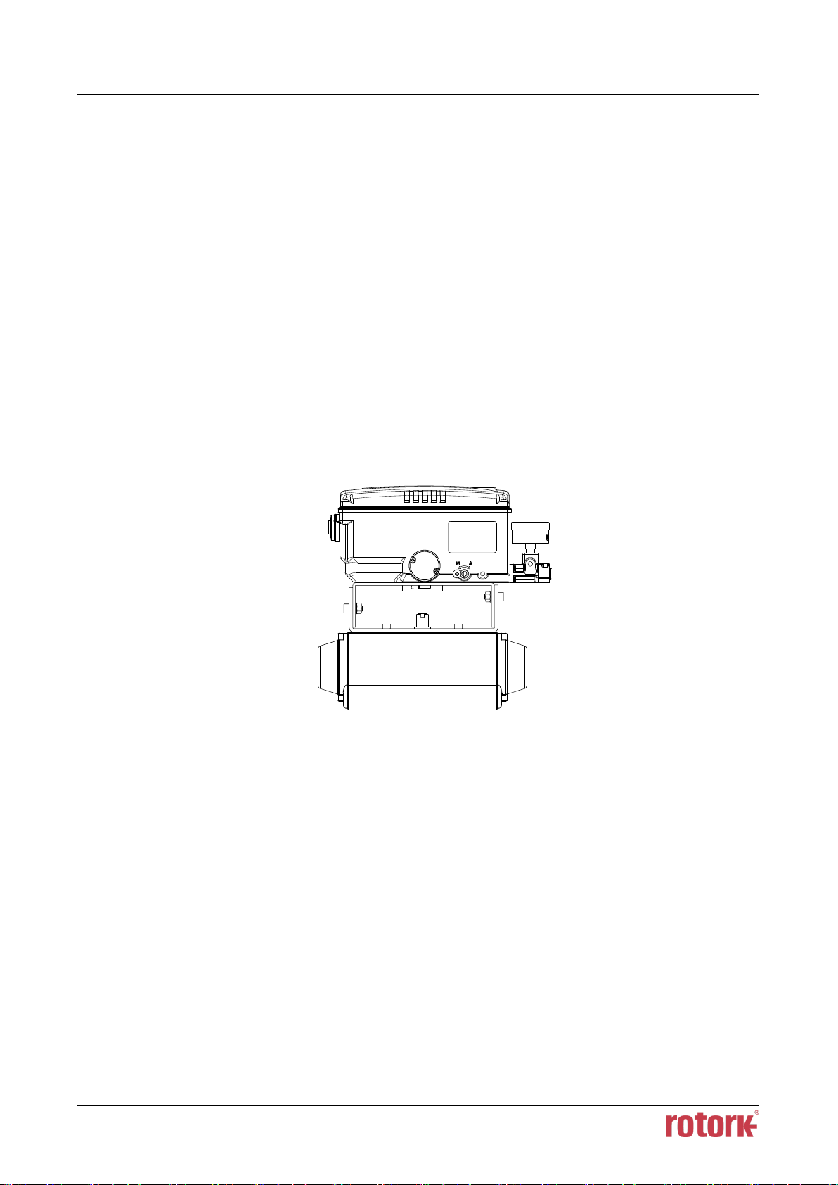
3.4 Rotary positioner Installation
Rotary positioner should be installed on rotary motion valve such as ball or butterfly type which uses
rack and pinion, scotch yoke or other type of actuators which its stem rotates 90 degrees. Before
proceeding with the installation, ensure following components are available.
3.4.1 YT-3700R / 3750R Components
➢ Positioner
➢ Rotary bracket set (2 pieces)
➢ 4 pcs x wrench headed bolts (M6 x 1P x 10L) : For the positioner and the upper bracket
➢ 4 pcs x wrench headed bolts (M6 x 1P x 15L) : For the brackets
➢ 4 pcs x M6 nuts : For the brackets
➢ 4 pcs x M6 spring washers : For the brackets
➢ Bolts and washers to attach bracket to actuator – not supplied with the positioner
Fig. 3-9: Installation of rotary positioner example

Smart Positioner
YT-3700 / 3750 Product Manual
Ver. 1.03 27
3.4.2 Rotary Bracket Information
The rotary bracket set (included with the positioner) contains two components. The bracket is
designed to fit onto the actuator with 20mm, 30mm and 50mm stem height (H) according to VDI/VDE
3845 standard. Please refer to below table how to adjust the height of the bracket.
Actuator stem
height (H)
Markings of bolt holes
A-L
B-L
A-R
B-R
20mm
H : 20
H : 20, 30
H : 20
H : 20, 30
30mm
H : 30
H : 20, 30
H : 30
H : 20, 30
50mm
H : 50
H : 50
H : 50
H : 50
Fig. 3-10: Brackets and positioner

Smart Positioner
YT-3700 / 3750 Product Manual
Ver. 1.03 28
Fig. 3-11: Actuator stem Height Fig. 3-12: Exploded Brackets
3.4.3 Rotary positioner Installation Steps
1. Please check the actuator’s stem height and adjust the brackets by referring to the above bracket
table.
2. Attached the brackets onto the actuator. It is recommended to use spring washer so the bolts will
not be loosen from vibration.
3. Set rotation position of the actuator stem at 0%. For single acting actuator, it is easy to check 0%
point by supplying no pressure to the actuator. For double acting actuator, check actuator
stem’s rotation direction – clockwise or counter-clockwise - by supplying pressure to the actuator.
4. Attach the positioner to the bracket. Setting alignment of center of main shaft of the positioner
and center of the actuator’s stem is very important. Poor alignment of the main shaft and the
actuator’s stem decreases the positioner’s durability due to unnecessary forces on the main shaft.
Fig. 3-13: Main shaft center alignment
5. Tighten the positioner and the bracket with bolts after checking the positioner’s position.

Smart Positioner
YT-3700 / 3750 Product Manual
Ver. 1.03 29
4 Connection - Air
4.1 Safety
➢ Supply pressure should be clean and dry air – avoiding moisture, oil and dust.
➢ Always recommended to use air filter regulator (i.e. YT-200 series).
➢ Rotork YTC Limited has not tested positioner’s operation with any other gases other than
clean air. Please contact Rotork YTC Limited for any questions.
4.2 Supply Pressure Condition
➢ Dry air with dew point of at least 10℃ lower than ambient temperature.
➢ Avoid from dusty air. Use 5 micron or smaller filter.
➢ Avoid oil.
➢ Comply with ISO 8573-1 or ISA 7.0.01.
➢ Supply pressure range is 0.14 ~0.7 MPa (1.4 ~ 7 bar)
➢ Set air filter regulator’s pressure level 10% higher than actuator’s spring range pressure.
4.3 Piping Condition
➢ Ensure inside of pipe is clean of obstructions.
➢ Do not use pipeline that is squeezed or shows any type of damamges.
➢ Pipeline should have more than 6mm of inner diameter (10mm outer diameter) to maintain flow
rate.
➢ The length of pipeline system should not be extremely long. Longer pipeline system may affect
flow rate due to the friction inside of the pipeline.

Smart Positioner
YT-3700 / 3750 Product Manual
Ver. 1.03 30
4.4 Connection – Piping with actuator
4.4.1 Single acting actuator
Singe acting type positioner is set to use only OUT1 port. OUT1 port of positioner should be
connected with supply port of actuator when using spring return actuator of single acting type.
Fig. 4-1: Single acting linear actuator Fig. 4-2: Single acting rotary actuator
4.4.2 Double acting actuator
Double acting type positioner is set to use OUT1 and OUT2 port. As input signal increases, the
supply pressure will be supplied through OUT1 port.
Fig. 4-3: Double acting linear actuator Fig. 4-4: Double acting rotary actuator
 Loading...