

Page 1
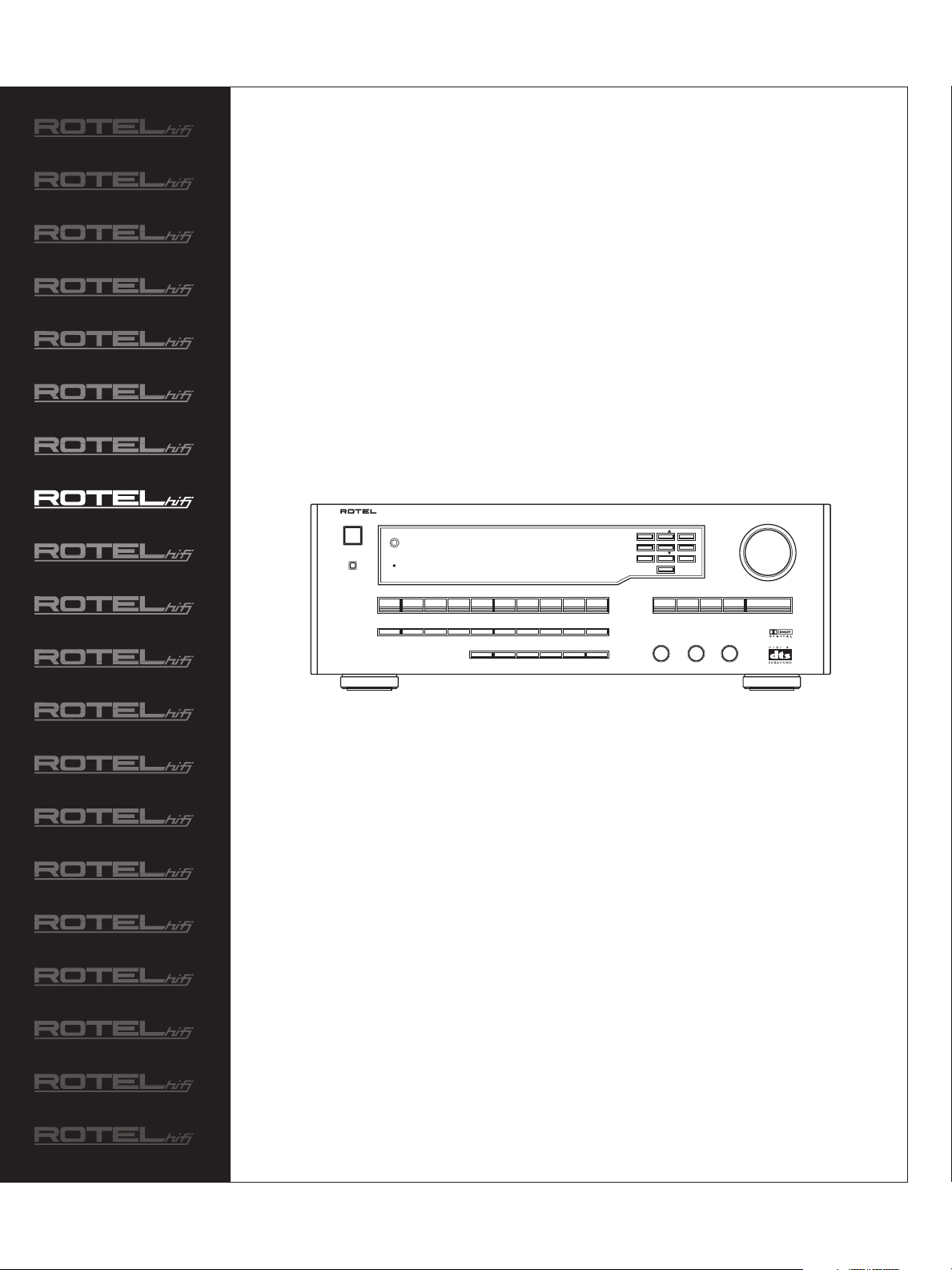
RTC-965
SURROUND SOUND
TUNER PREAMPLIFIER
SURROUND SOUND TUNER PREAMPLIFIER RTC-965
POWER
STANDBY
REMOTE SENSOR
STANDBY
TAPE 2
MONITORTAPE 1TUNERPHONO VIDEO 3CD
DYNAMIC
RANGESTEREO3 STEREOPRO-LOGIC
SUBWOOFER+–REAR
VIDEO 2VIDEO 1
SPEAKER
MODEMENU
AUX/
VIDEO 4
VIDEO 5
5.1 CH
VIDEO
VIDEO 1
INPUTDSP
LABELS
REC
CENTER
+–
+–
1 2 3
4 BACK 5 6 ENTER
7 8 9
0
FREQUENCY
DIRECTMEMORY MONO BAND < TUNING >
BASS
TREBLE BALANCE
Owner’s Manual
MASTER VOLUME
Page 2
CAUTION
RISK OF ELECTRIC SHOCK
DO NOT OPEN
CAUTION: TO REDUCE THE RISK OF ELECTRIC SHOCK, DO
NOT REMOVE COVER. NO USER-SERVICEABLE PARTS INSIDE.
REFER SERVICING TO QUALIFIED SERVICE PERSONNEL.
APPLICABLE FOR USA, CANADA OR WHERE
APPROVED FOR THE USAGE
CAUTION: TO PREVENT ELECTRIC SHOCK, MA TCH WIDE BLADE
OF PLUG TO WIDE SLOT. INSERT FULLY.
ATTENTION: POUR EVITER LES CHOCS ELECTRIQUES,
INTRODUIRE LA LAME LA PLUS LARGE DE LA FICHE
DANS LA BORNE CORRESPONDANTE DE LA PRISE ET
POUSSER JUSQU AU FOND.
This symbol is to alert the user to the
presence of uninsulated dangerous
voltages inside the product's enclosure
that may constitute a risk of electric shock.
This symbol is to alert the user to important
operating and maintenance (service)
instructions in this manual and literature
accompanying the product.
WARNING:
There are no user serviceable parts inside. Refer all servicing to qualified service personnel.
WARNING:
To reduce the risk of fire or electric shock, do not expose the unit to moisture
or water. Do not allow foreign objects to get into the enclosure. If the unit is
exposed to moisture, or a foreign object gets into the enclosure, immediately
disconnect the power cord from the wall. Take the unit to a qualified service
person for inspection and necessary repairs.
Read all the instructions before connecting or operating the component. Keep
this manual so you can refer to these safety instructions.
Heed all warnings and safety information in these instructions and on the
product itself. Follow all operating instructions.
Clean the enclosure only with a dry cloth or a vacuum cleaner.
You must allow 10 cm or 4 inches of unobstructed clearance around the unit. Do
not place the unit on a bed, sofa, rug, or similar surface that could block thenotdmatiit ookcasof ficabinet,re. ncl73(oubock the)Tjt ratst do oure. Icabinetbol isust TDphe poolopections.
Page 3
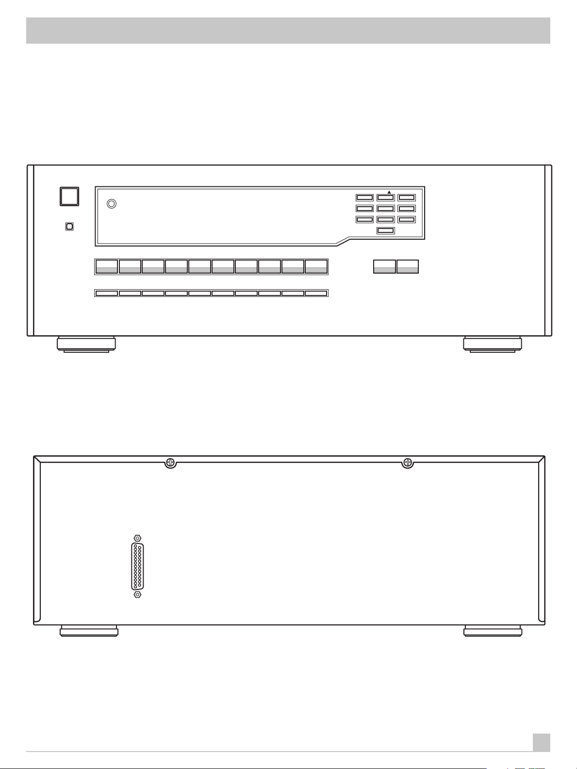
Figure 1: Controls and Connections
REMOTE SENSOR
RTC-965
1 2 3
4 BACK 5 6 ENTER
7 8 9
0
3
Page 4
SURROUND SOUND TUNER PREAMPLIFIER RTC-965
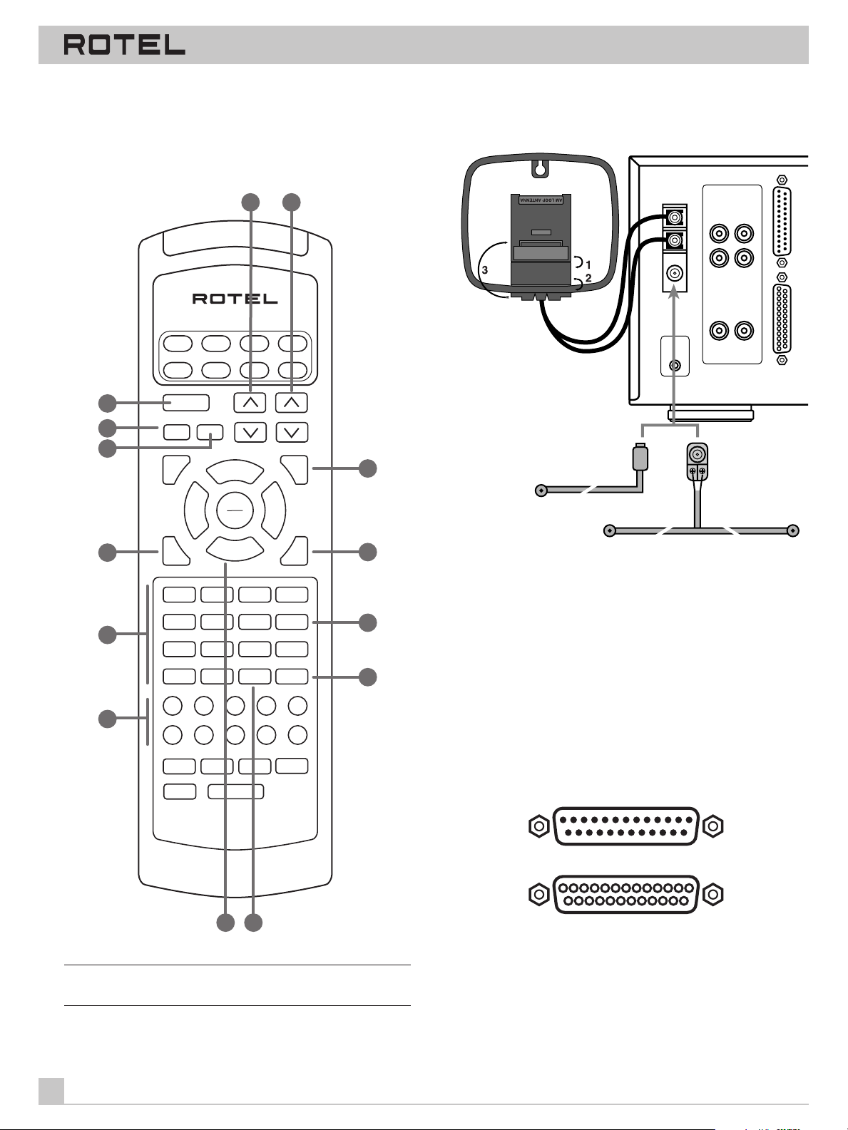
Figure 2: Remote Control
AUD
SATCDTV
43
44
45
46
47
POWER
BAND
MUTE
T / V
SURROUND + ON SCREEN
GUIDE
TRACK – TRACK +
SEARCH –
UP DOWN
RECALL
OPN/CLS SUR-DELAY
1 2 3
DISC 1 DISC 2 DISC 3 PROG
4 5 6
DISC 4 DISC 5 DISC 6 TIME [REVIEW]
7 8 9
10 0 ENTER
PAUSE
C. DELAY
PLAY
SEL
STOP
DYNAMIC
41
TAPE
VOL
VCR
42
DVD
CBL
CH
MENU
SEARCH +
PRE
MOVIE FILT
5.1 CH
SELECT
CLEAR [SCAN]
BACK
RANDOM [REPEAT]>10
Figure 3: Antenna Connections
ANTENNA
LR
CENTER
PREOUT
FRONT
REAR
SUB
WOOFER
PREOUT
5.1 CH OUTPUT
5.1 CH INPUT
AM
LOOP
FM
75Ω
REMOTE
EXT IN
49
CH
50
51
52
48
CD TUNER VIDEO 4
VIDEO 1
M 1 M 2 M 3
[SHIFT]
LIGHT
AUX/V5
VIDEO 2 VIDEO 3TAPE 1 TAPE 2
PHONO
M 4
RR-939
5354
NOTE: See PROGRAMMING THE RR-939. Audio code for RTC-965
is code 001.
4
Figure 4: DB25 Connector Pin Assignments
1312111098765432
2524232221201918171615114
123456789101112
14151617181920212223241325
1 left front
2 center
3 right front
4 subwoofer
5 left surround
6 rear surround
+
+
14 left front GND
15 center GND
+
16 right front GND
+
17 subwoofer GND
+
18 left surround GND
+
19
right surround GND
Page 5
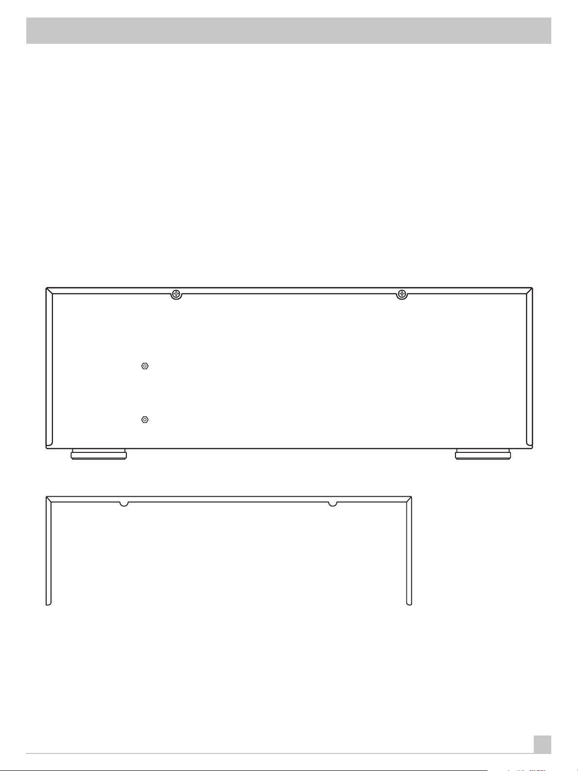
Figure 5: Output Connections
RTC-965
5
Page 6
SURROUND SOUND TUNER PREAMPLIFIER RTC-965
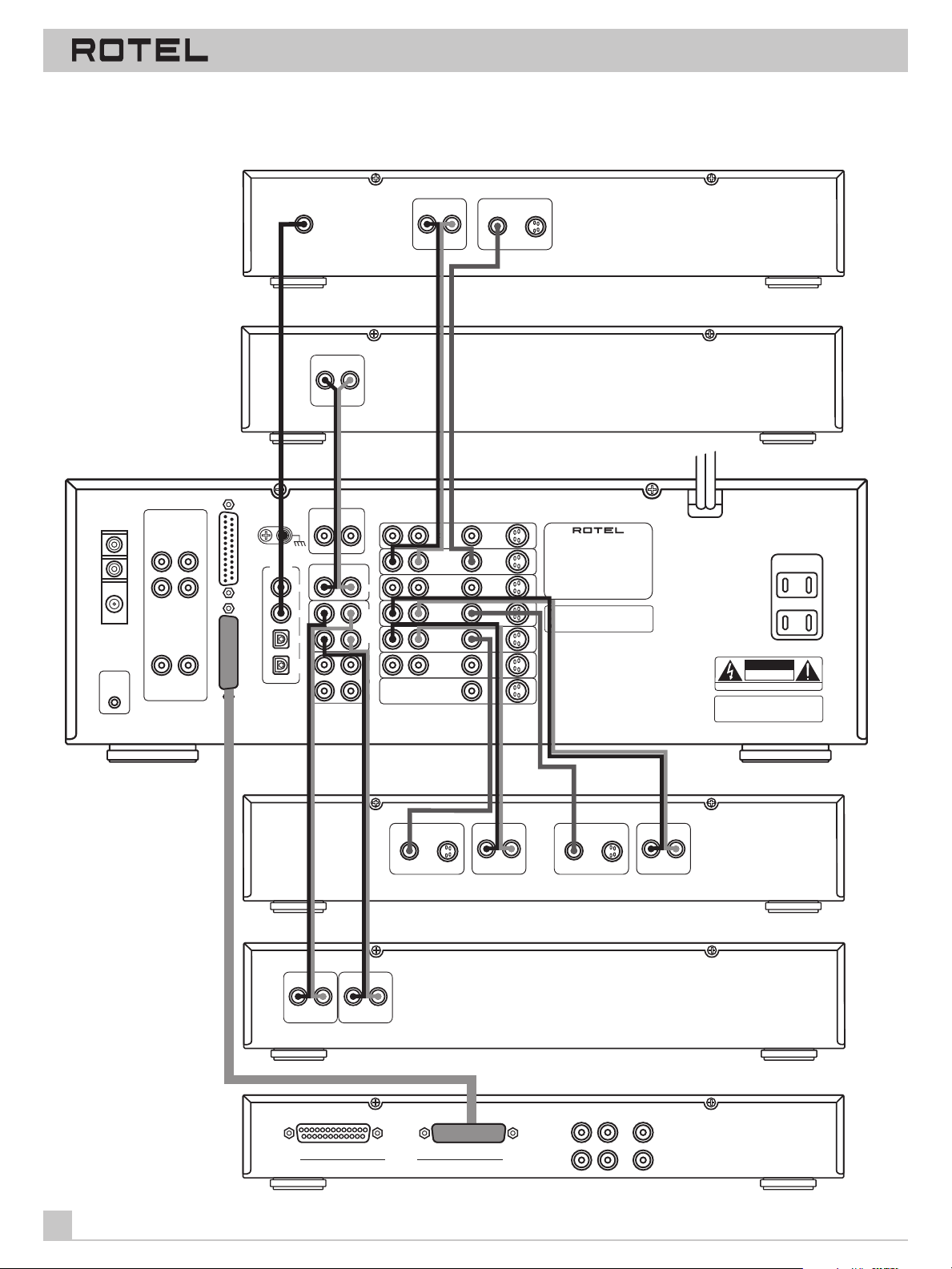
Figure 6: RCA Input Connections
DVD PLAYER
AM
LOOP
FM
75Ω
ANTENNA
REMOTE
EXT IN
LR
FRONT
REAR
CENTER
PREOUT
SUB
WOOFER
PREOUT
GND
DIGITAL INPUT
VIDEO
5.1 CH OUTPUT
5.1 CH INPUT
DIGITAL OUT
2
3
4
AUX
5
ANALOG OUTPUT
L
R
PHONO
LR
LR
CD
IN
TAPE1
OUT
IN
TAPE 2
MON
OUT
AUDIO OUT
L
VIDEO 4
VIDEO 3
VIDEO 2
VIDEO 1
PLAY
VIDEO 1
AUX/
VIDEO 5
TV MONITOR
VIDEO OUT
S-VIDEOCOMPOSITE
R
CD PLAYER
ROTEL RTC-965
AC
S-VIDEOCOMPOSITELR
SURROUND SOUND
TUNER PREAMPLIFIER
MODEL NO. RTC-965
RTC-965
WARNING:TO REDUCE THE RISK OF FIRE
OR ELECTRICAL SHOCK, DO NOT EXPOSE
THIS EQUIPMENT TO RAIN OR MOISTURE.
REC
INPUT
SWITCHED
100W MAX
CAUTION
RISK OF ELECTRIC SHOCK
DO NOT OPEN
AVIS:
RISQUE DE CHOC ELECTRIQUE–NE PAS OUVRIR
WARNING:TO REDUCE THE RISK OF FIRE
OR ELECTRICAL SHOCK, DO NOT EXPOSE
THIS EQUIPMENT TO RAIN OR MOISTURE.
VCR
L
AUDIO OUT
R
VIDEO IN
L
S-VIDEOCOMPOSITE
R
AUDIO IN
S-VIDEOCOMPOSITE
VIDEO OUT
CASSETTE RECORDER
L
R
L
R
LINE OUTPUT
REC INPUT
OUTBOARD DECODER
FRONT REAR
L
5.1 CH
OUTPUTINPUT
R
6
CENTER
SUBWOOFER
Page 7
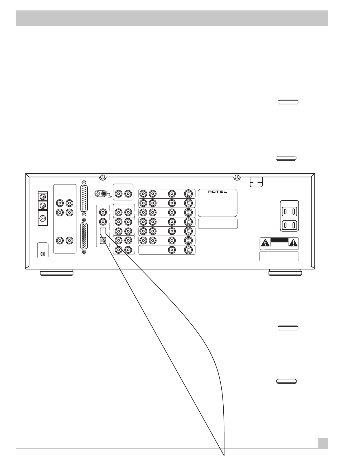
Figure 7: S-Video Input Connections
RTC-965
AM
LOOP
FM
75Ω
ANTENNA
REMOTE
EXT IN
CENTER
PREOUT
FRONT
REAR
SUB
WOOFER
PREOUT
DIGITAL INPUT
VIDEO
5.1 CH INPUT
GND
AUX
2
3
4
5
PHONO
LR
LR
TAPE1
OUT
TAPE 2
MON
OUT
S-VIDEOCOMPOSITELR
VIDEO 4
VIDEO 3
CD
IN
IN
VIDEO 2
VIDEO 1
PLAY
VIDEO 1
AUX/
VIDEO 5
TV MONITOR
REC
SURROUND SOUND
TUNER PREAMPLIFIER
MODEL NO. RTC-965
RTC-965
WARNING:TO REDUCE THE RISK OF FIRE
OR ELECTRICAL SHOCK, DO NOT EXPOSE
THIS EQUIPMENT TO RAIN OR MOISTURE.
SWITCHED
100W MAX
CAUTION
RISK OF ELECTRIC SHOCK
DO NOT OPEN
AVIS:
RISQUE DE CHOC ELECTRIQUE–NE PAS OUVRIR
WARNING:TO REDUCE THE RISK OF FIRE
OR ELECTRICAL SHOCK, DO NOT EXPOSE
THIS EQUIPMENT TO RAIN OR MOISTURE.
7
Page 8
SURROUND SOUND TUNER PREAMPLIFIER RTC-965
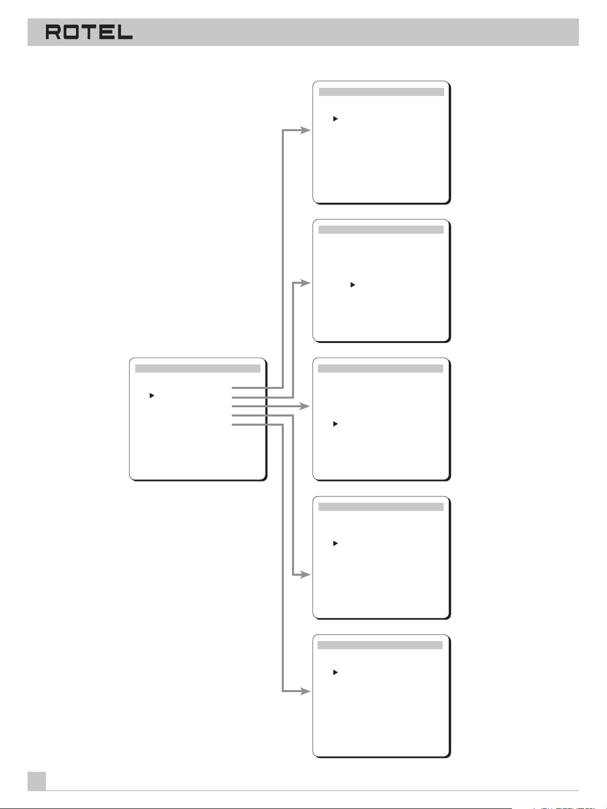
Figure 8: On-Screen Menus
INPUT SELECTOR
Video: DVD
Audio: TUNER
Video REC: DVD
Audio REC: TUNER
5.1Ch Input: OFF
Input Source: AUTO
DOWN–selection ENTER–change
BACK-return MENU-screen off
SURROUND MODE
Mode: DOLBY PRO LOGIC
Delay Time
CENTER: ____
REAR: 20ms
BASS LEVEL: +10dB
DOWN–select ENTER/VOL–change
BACK-return MENU-screen off
MAIN MENU
Input Selector
Surround Mode
Test Tone
Tone/Balance
Setup Menu
DOWN–selection ENTER–change
BACK-return MENU-screen off
TEST TONE
Front - L
Center 0dB
Front - R
Rear - R 0dB
Rear - L -5dB
Subwoofer 0dB
DOWN–selection VOLUME–change
BACK-return MENU-screen off
TONE / BALANCE
Bass : +10dB
Treble : +10dB
Balance : L 10
DOWN–selection VOLUME–change
BACK-return MENU-screen off
SETUP MENU
Front: LARGE
Rear: SMALL
Center: LARGE
Subwoofer: YES
Dynamic Range: OFF
Menu Display: SCREEN
DOWN–selection ENTER–change
BACK-return MENU-screen off
8
Page 9
RTC-965
○○ ○○○○○○○○○○○○○○○○○○○○○○○○○○○○○○○
Contents
Figure 1: Controls and Connections 3
Figure 2: Remote Control 4
Figure 3: Antenna Connections 4
Figure 4: DB25 Connector Pin Assignments 4
Figure 5: Output Connections 5
Figure 6: RCA Input Connections 6
Figure 7: S-Video Input Connections 7
Figure 8: On-Screen Menus 8
About Rotel _________________________________________ 10
Getting Started _____________________________________ 10
RTC-965 Key Features 10
Unpacking 10
Placement 10
Front Panel: Basic Controls ___________________________ 10
1
Power Switch
Remote Sensor
Front Panel Display
Master Volume Control
Tone Controls
Balance Control
and Standby Switch 2
3
4
6 41
21
22
SUBWOOFER/REAR/CENTER +/– Buttons
MEMORY Button
19
Front Panel: Input Selection/Recording Controls _______ 11
Input Source Buttons
5.1 CH Input
15
VIDEO 1 REC Button
7
51
17
Front Panel: Surround Sound Controls ________________ 12
11
8
9
54
12
PRO LOGIC Button
3 STEREO Button
DSP Button
10
STEREO Button
DYNAMIC RANGE Button
Front Panel: Tuning Controls _________________________ 13
24
BAND Button
TUNING Button
NUMERIC Keypad: Station Presets
FREQUENCY DIRECT Button
MONO Button
25 42
23
45
5 47
20
Front Panel: Configuration Controls __________________ 14
13
16
14
49
VIDEO LABEL Button
SPEAKER MODE Button
MENU Button
18
43
11
11
11
11
11
11
11
11
11
12
12
12
12
12
13
13
13
13
13
14
14
14
14
15
RR-939 Remote Control ______________________________ 15
Programming the RR-939 16
POWER Button
VOLUME Buttons
TUNING Button
INPUT SOURCE Buttons
5.1 Button
BAND Button
NUMERIC Buttons
DYNAMIC Button
43
41
42
48
51
45
47
54
MUTE Button (remote only)
MENU button
49
44
16
16
16
16
16
16
16
16
16
16
Rear Panel Connections: Overview ___________________ 17
Rear Panel: Audio Source Connections ________________ 17
30
Phono Inputs
CD Inputs
and Phono Ground
31
Tape Inputs and Outputs
38
29
17
17
17
Rear Panel: Video Source Connections ________________ 17
VIDEO 1 Inputs/Outputs
VIDEO 2 – 5 Inputs
Digital Inputs
32
37
5.1 Channel Audio Input
32
36
17
18
18
18
Rear Panel Output Signal Connections ________________ 18
TV Monitor Output
RCA Preamp Outputs
39
27
5.1 CHANNEL Preamp Outputs
28
18
18
18
Rear Panel Antenna Connections _____________________ 19
AM Loop Antenna
FM Wire Antenna
26
35
19
19
Rear Panel AC Power Connections ____________________ 19
AC Input
AC Convenience Outlets
40
33
Remote External Sensor Jack
34
19
19
19
On-Screen Display / Configuration ____________________ 19
Navigation Buttons
41 46
49 50 52
53
20
MAIN Menu 20
INPUT SELECTOR Menu 21
SURROUND MODE Menu 21
TEST TONE Menu 22
TONE/BALANCE Menu 22
SETUP Menu 23
RTC-965 Specifications_______________________________ 23
9
Page 10
SURROUND SOUND TUNER PREAMPLIFIER RTC-965
○○ ○○○○○○○○○○○○○○○○○○○○○○○○○○○○○○○
About Rotel
A family whose passionate interest in music led them to manufacture high fidelity components of uncompromising quality founded
Rotel over 30 years ago. Through the years that passion has remained undiminished and the family goal of providing exceptional
value for audiophiles and music lovers regardless of their budget,
is shared by all Rotel employees.
The engineers work as a close team, listening to, and fine tuning
each new product until it reaches their exacting musical standards. They are free to choose components from around the world
in order to make that product the best they can. You are likely to
find capacitors from the United Kingdom and Germany, semi conductors from Japan or the United States, while toroidal power
transformers are manufactured in Rotel’s own factory.
Rotel’s reputation for excellence has been earned through hundreds of good reviews and awards from the most respected reviewers in the industry, who listen to music every day. Their
comments keep the company true to its goal - the pursuit of
equipment that is musical, reliable and affordable.
All of us at Rotel, thank you for buying this product and hope it will
bring you many hours of enjoyment.
•
Comprehensive digital and analog input and output connections
for audio and video sources, including digital inputs, composite
video inputs and S-Video inputs
•
AM/FM tuner with 30 station presets, direct access tuning, and
auto-tuning.
•
Programmable remote control to operate the RTC-965 and up to
seven other components.
Unpacking
Remove the unit carefully from its packing. Look for the handheld
remote control and other accessories. Save the packing and box
as it will protect the RTC-965 if you move or need to return it for
maintenance.
Placement
Place the RTC-965 on a solid, dry, level surface away from direct
sunlight, excessive heat, high humidity, or strong vibrations.
Make sure the RTC-965 is close to the other components in your
audio/video system and, if possible, place it on its own shelf. This
will make initial cable routing, hookup, and any subsequent system changes easier. It also minimizes potential interference or
heat buildup from other components.
○○ ○○○○○○○○○○○○○○○○○○○○○○○○○○○○○○○
Getting Started
Thank you for purchasing the Rotel RTC-965 Surround Sound
Tuner Preamplifier. The RTC-965 is four products in one:
1. A digital audio/video processor designed to decode Dolby
®
Logic
analog surround signals plus Dolby Digital® and DTS® digi-
tal surround sound signals
2. A full-featured audio/video control center for analog and digital
source components
3. A high-quality AM/FM tuner.
RTC-965 Key Features
•
Rotel’s Balanced Design Concept combines advanced circuit
board layout, comprehensive parts evaluation, and extensive listening tests for superior sound and long term reliability.
•
Dolby® Pro Logic® decoding for analog sources
•
Dolby Digital® and DTS® decoding for 5.1 channel digital sources
•
5.1 channel input for outboard adaptor and future upgradeabilty
®
Pro
Make sure there is enough room behind the RTC-965 for easy
hookup. Remember, you are connecting many other components
to this unit and you’ll probably need more space than you think.
Don’t stack other objects (components or other items) on top of
the RTC-965. Don’t let water fall into the RTC-965 as this could
damage delicate circuitry.
○○ ○○○○○○○○○○○○○○○○○○○○○○○○○○○○○○○
Front Panel: Basic Controls
We suggest you look over the RTC-965’s front and rear panels before you start connecting other components to it. The following
explanations will help you get familiar with the units connections,
features, and controls, with number references corresponding to
the illustrations at the front of this manual.
Most functions are duplicated on the front panel and on the
handheld remote control shipped with your unit. A few may be
available only on one or the other. When two reference numbers
appear, one refers to the location of the button on the front panel,
the other to the location of the button on the handheld remote
control.
Note: Front panel controls and displays used for tuning the AM/
FM receiver are described in the next section of this manual.
•
User friendly ON-SCREEN DISPLAY with programmable labels for
video components.
10
Page 11
RTC-965
Power Switch 1 and Standby Switch 2
The RTC-965 has two pushbuttons for powering on and off. The
POWER switch completely shuts down all of the circuitry, similar
in effect to removing the power cord from the AC outlet. The
STANDBY switch deactivates the unit, but preserves power to
some circuits such as those that store memorized circuits. When
in STANDBY mode, a front panel STANDBY LED indicator lights.
The STANDBY Switch is duplicated on the RTC-965's remote.
In normal operation, use the STANDBY switch to deactivate the
unit when you are finished listening and leave the POWER switch
ON at all times. This will preserve memory functions.
Note: The STANDBY switch also controls the rear panel AC convenience outlets. When the RTC-965 is in STANDBY mode, the AC
outlet is also off. When the RTC-965 is fully functional, the AC outlet is live.
Remote Sensor
This sensor receives infrared signals from the handheld remote
control. Make sure you do not accidentally block this sensor with
cables or accessories.
Front Panel Display
3
4
43
SUBWOOFER/REAR/CENTER +/– Buttons
These three pairs of buttons are used to adjust the output level of
the subwoofer channel, the rear surround speakers, and the center channel speaker.
To change the output volume of the subwoofer, press the
SUBWOOFER + or – buttons. To change the output volume of the
rear surround channels press the REAR + or – buttons. To adjust
the output of the center channel, press the CENTER + or – button.
Note: The same adjustments can also be made using the ONSCREEN MENU system and test tones during system setup.
MEMORY Button
The MEMORY button is used to confirm and memorize various settings in the setup and operation of the RTC-965, including tuner
station presets and video source labels. Its use is described in detail in the relevant sections below.
○○ ○○○○○○○○○○○○○○○○○○○○○○○○○○○○○○○
19
18
Front Panel: Input Selection/ Recording Controls
The large fluorescent display in the upper portion of the RTC-965
provides status information used in operating the AM/FM receiver
(such as station frequency display, band, preset memory, etc.).
Master Volume Control 6
The MASTER VOLUME control adjusts the level of all output channels simultaneously. Rotate the control clockwise to increase the
volume. Rotate counterclockwise to decrease the volume. MASTER VOLUME buttons are also available on the RTC-965's
handheld remote control.
When you adjust the volume, a digital readout will appear in the
RTC-965 front panel display and an indication of the new setting
will appear on your TV monitor.
Tone Controls
BASS and TREBLE controls increase and decrease the audio
signal’s low and high frequency content respectively. Rotate
clockwise to increase output in the respective frequency range
and counterclockwise to reduce it. The center detent removes
each control from the audio path for maximum signal integrity. The
front panel display and an ON-SCREEN DISPLAY will show tone
control settings as you adjust them.
Balance Control
Turn the BALANCE control clockwise to increase the output level
of the right channel speakers. Turn counterclockwise to increase
the output level of the left channel speakers. The center detent
position removes the control from the circuit and provides equal
output from both left and right channels.
21
22
41
Input Source Buttons
Ten large front panel buttons directly select an audio or video input source (such as a CD player, the built-in tuner, a tape recorder,
video sources, etc.) for listening. Push any of these buttons (or the
duplicates on the handheld remote) to select the desired source.
You will hear this source and, if you have selected a video source,
see its picture on your TV monitor.
Both the front panel display and the ON-SCREEN DISPLAY will
show the current source selection. These labels can be customized to match your components (see the VIDEO LABEL button below).
Note: Four video inputs accept analog audio/video signals and
digital signals including Dolby Digital and DTS surround material.
If a digital signal is present when the source is selected, the digital input is automatically activated and the proper surround
choice enabled – unless the automatic sensing has been overridden for that input in the setup procedure described in the section
on System Configuration. If no digital signal is present or if the
auto sensing has been disabled, the analog inputs are selected.
TAPE MONITOR INPUTS: Two of the INPUT SOURCE buttons have
a special function. The TAPE 1 and TAPE 2 MONITOR buttons activate the analog inputs of a tape monitor loop consisting of a pair
of outputs and a matching set of inputs. Traditionally, this tape
monitor loop has been used to play a tape deck connected to
these inputs or for real time monitoring of a recording in progress
on an audio tape deck. Alternatively, the tape monitor loop could
be used to pass a signal to a graphic equalizer and listen to the
processed signal by pressing the corresponding TAPE MONITOR
button. An indicator appears in the front panel display when TAPE
2 MONITOR is activated.
7
11
Page 12
SURROUND SOUND TUNER PREAMPLIFIER RTC-965
5.1 CH Input 15
This button overrides all other inputs (both analog and digital) and
directly connects an external digital adaptor to the RTC-965’s
MASTER VOLUME control and outputs. This allows the RTC-965 to
remain the central controller for even the most advanced audio/
video systems and provides an upgrade path to future software
standards. When activated, all of the RTC-965’s inboard Dolby processing is bypassed. An indicator appears in the front panel display and the ON-SCREEN DISPLAY when the 5.1 CH input is
activated.
The 5.1 CH button is duplicated on the handheld remote control.
VIDEO 1 REC Button
The RTC-965 permits recording from any source connected to the
VIDEO 2 through 5 inputs to a VCR connected to the VIDEO 1 outputs while allowing simultaneous listening to another input
source. To select a VIDEO INPUT SOURCE for recording, press the
VIDEO 1 REC button. Each time you press the button, one of the
VIDEO INPUT sources will be shown in the front panel display and
selected for recording. For example, the first time you press the
button, VIDEO 2 will be displayed as the recording source, a second press of the button will display VIDEO 3, and so on until you
have cycled through VIDEO 4 and AUX/VIDEO 5 as well. Stop
when you reach the input you wish to record from and its signal
will be available to record on a VCR connected to the VIDEO 1 outputs. Remember, this selection is independent of the listening
source. While recording, you may still select an audio source (for
example, the CD or the TUNER input) for listening.
51
17
Note: The RECORD function requires analog signals. Thus, if you
are using a digital connection from a CD player or DVD for listening, you should also connect an analog signal for recording. See
the section on Rear Panel Input Connections.
ery time you play a stereo CD or listen to a stereo FM broadcast.
To the contrary, many people find that they prefer one of the other
surround modes. We have provided a note with each surround
mode description suggesting when the setting may be appropriate
along with alternative settings.
As a general rule, we recommend using PRO LOGIC mode for all
sources labeled Dolby Pro Logic. Beyond that, use whatever settings sound best to you in your room with your system.
Note: Some users understandably find the choice of surround
modes overwhelming, particularly until they have had a chance to
live with the system and experiment for a while. Others simply
prefer “set it and leave it” convenience. In both cases, we recommend PRO LOGIC mode as a satisfactory choice for virtually any
source material.
PRO LOGIC Button
Provides proper playback decoding and processing for any Dolby
Pro Logic encoded surround sound material, whether it be a music CD, videotape, videodisc, conventional stereo TV broadcast, or
radio broadcast. It also can be used successfully to create additional ambience in 2-channel musical source material. Front, center, and rear speakers are activated and an indicator lights in the
front panel display when the PRO LOGIC button is pressed.
8
Note: Many users will find that leaving the RTC-965 in the PRO
LOGIC mode offers the most satisfactory performance and convenience for all source materials. It provides automatic decoding of
analog surround sound material. It allows automatic selection
(unless overridden) of digital processing when a Dolby Digital or
DTS source is played. In addition, it provides satisfying surroundsound ambience with musical sources.
○○ ○○○○○○○○○○○○○○○○○○○○○○○○○○○○○○○
Front Panel: Surround Sound Controls
The RTC-965 is equipped to properly decode Dolby® Pro Logic®,
Dolby Digital
as synthesizing several different ambience simulations for musical source material.
Dolby Digital and DTS activation are fully automatic (unless the
auto sensing is disabled during system setup). When a digital signal encoded with either of these surround signals is detected, the
RTC-965 automatically activates the proper decoding. In most
cases, the RTC-965 will also recognize a digital signal encoded
with Dolby Pro Logic for automatic processing.
Additionally, five small buttons allow manual control of the surround sound/ambience settings as described below. Keep in mind
that there are no right or wrong settings. Just because a mode is
labelled STEREO does not mean that you must use this mode ev-
12
®
, and DTS® surround sound source material as well
3 STEREO Button
Provides the proper playback of Dolby Pro Logic source material
on systems that have front and center speakers, but lack rear surround speakers. Adds the rear channel signals to the front speakers for a larger, more ambient sound than conventional stereo. An
indicator lights in the front panel display to show that this mode
has been activated.
DSP Button
This button activates digital synthesis of four different ambience
modes (MUSIC 1: THEATER, MUSIC 2: HALL, MUSIC 3: STADIUM,
and MUSIC 4: CHURCH) which simulate different acoustic environments and are primarily used to recreate ambience when listening to music sources and/or other sources that lack surround
sound encoding.
These four modes vary in the length and type of delay used for the
rear surround channel signals. Experiment to find a setting which
is most pleasing for a particular recording or broadcast. Press the
button to activate the DSP mode. Each subsequent press of the
button will step forward to the next mode in the following order:
MUSIC 1 > MUSIC 2 > MUSIC 3 > MUSIC 4. An indicator lights in
the front panel display when DSP mode has been activated.
10
9
Page 13
RTC-965
○○ ○○○○○○○○○○○○○○○○○○○○○○○○○○○○○○○
Note: As a general rule, the DSP modes provide more exaggerated ambience effects than playing the same recording in PRO
LOGIC mode, which provides a subtle ambience synthesis on musical recordings. You may prefer PRO LOGIC as your “everyday”
setting, experimenting with the more spectacular DSP modes for
particular recordings or effects.
STEREO Button
Activates conventional 2-speaker stereo direct bypass mode with
no surround sound or other processing. This is “pure” stereo, using the front left and front right speakers only, with no surround
channels and no center channel.
When used with Dolby Digital or DTS source material, the STEREO
button engages a “downmix” feature which combines all of the
available channels and sends them to the front speakers only. The
spatial effects of surround sound are lost, but all of the information on the original recording will be heard in 2-channel stereo.
11
Note 1: We provide the STEREO mode as an alternative for those
who want to hear the recording in its original two-channel form,
as if it were being played over a conventional 2-speaker stereo
system. Conversely, many listeners find that they prefer the additional ambience from multi-speaker surround sound processing of
2-channel music recordings. We suggest PRO LOGIC mode for
subtle ambience synthesis or the DSP modes for more spectacular effects. Use the setting that sounds best to you.
DYNAMIC RANGE Button 12
Today’s digital sources are capable of extremely high dynamic
range (the difference between the softest and loudest sounds). In
some cases, the available dynamic range may tax amplifiers and/
or speakers. In other cases, it may be desirable to reduce the dynamic range, for example, when listening at low volume levels.
Pressing the DYNAMIC RANGE button steps through the three
available dynamic range settings:
• OFF (no compression/full dynamic range)
• MID (moderate compression)
• MIN (maximum compression/minimum dynamic range).
54
Front Panel: Tuning Controls
The RTC-965 features a digital synthesized AM/FM tuner with 30
station presets. Operation of the tuning functions involves the use
of the numeric buttons immediately to the left of the MASTER
VOLUME knob and five buttons directly below the MASTER VOLUME knob as described below.
BAND Button 24
The BAND button selects whether the tuner is in AM or FM mode.
Press the button to toggle back and forth between AM and FM. A
corresponding indicator will light at the left portion of the front
panel display to confirm your choice and the currently tuned station frequency will be shown.
TUNING Button 25
This is a rocker switch used to change the station frequency up or
down. The TUNING button gives you a choice of two tuning methods: manual and automatic.
To tune manually, press the button quickly and release to increase or decrease the station frequency to the next available
setting, whether or not there is a station broadcasting on that frequency. Use a succession of quick button presses to reach the
desired station.
To tune automatically, press and hold the TUNING button for approximately one second. An AUTO indicator will appear in the
front panel display and the tuner will begin automatically scanning up or down through the frequencies until the next available
station is detected. If this is not the desired station, repeat the automatic tuning procedure to find the next station. Weak stations
will be skipped during auto tuning.
Several indicators in the front panel display assist tuning. A large
display shows the tuned frequency and increases or decreases
during tuning. A signal strength indicator shows the strength of
the incoming signal. A TUNED indicator lights when a sufficiently
strong signal is received. A ST indicator lights when a stereo FM
signal is received.
NUMERIC Keypad: Station Presets 5
45
42
47
An indicator lights on the front panel display to show the current
selection.
Note: The DYNAMIC RANGE feature is only available in Dolby
Digital. It is inactive at all other times.
The RTC-965 can store up to 30 station presets for recall at any
time using the NUMERIC keypad. To memorize a station:
1. Tune to the desired station, either AM or FM.
2. Press the MEMORY button on the front panel of the RTC-965. A
MEMORY indicator will flash for five seconds in the display.
3. While the MEMORY indicator is flashing, press the number of
the preset where you wish to store the station frequency. For example, to memorize the station as preset 3, press the 3 button. To
memorize preset 15, press the 1 button followed by the 5 button.
4. A previously stored frequency is erased from memory when a
new frequency is memorized for the same preset number.
13
Page 14
SURROUND SOUND TUNER PREAMPLIFIER RTC-965
To tune to a previously memorized station, just press the preset
number on the NUMERIC keypad. For example, to tune to preset 3,
press the 3 button. To tune to preset 15, press the 1 button and
then press the 5 button.
Note: If the TUNER is not already the selected INPUT SOURCE, selecting a station preset will automatically switch to the TUNER input and tune the memorized station.
The NUMERIC keypad buttons can also be used for direct access
tuning (see below). In addition, four of the buttons (
ENTER) are used in navigating the ON-SCREEN MENU system.
FREQUENCY DIRECT Button
If you know the frequency of the desired station, you may tune it
directly using the FREQUENCY DIRECT button and the NUMERIC
keypad.
1. Press the FREQUENCY DIRECT button to change the NUMERIC
keypad from station preset to Direct Access mode. The station
frequency in the front panel display will change to a series of four
bars, representing the digits of a station frequency, with the first
bar flashing.
2. Enter the first digit of the station frequency using the NUMERIC
keypad. The digit will appear in the frequency display and the second bar will flash. Enter the remaining digits of the frequency.
Note that in FM mode, pressing 1 will enter 10 as the digit in the
frequency display. When all of the digits have been entered, the
tuner will automatically tune to the displayed station frequency.
Examples: FM87.50MHz Press: 8 > 7 > 5 > 0
FM101.90MHz Press: 1 > 1 > 9 > 0
AM1610kHz Press: 1 > 6 > 1 > 0
20
/ BACK /
○○ ○○○○○○○○○○○○○○○○○○○○○○○○○○○○○○○
Front Panel: Configuration Controls
VIDEO LABEL Button
You may customize the labels of the VIDEO INPUT SOURCE buttons so that the names of your particular components are displayed in the front panel display and the ON-SCREEN DISPLAY
when selected. For example, you could choose to have DVD displayed in place of VIDEO 2. Labels may be up to 9 characters long.
Inputs that can be relabelled are VIDEO 1, VIDEO 2, VIDEO 3,
VIDEO 4, and AUX/VIDEO 5. To relabel the video inputs:
1. Select the VIDEO INPUT you wish to relabel.
2. Press and hold the VIDEO LABEL button for 3 seconds. The 9
segments of the front panel display turn to bars, each representing one available character. The first bar blinks.
3. Press the TUNING < > buttons repeatedly to step backwards or
forwards through the available characters until you find the first
letter or character in the desired name. Available characters include the 26 letters of the alphabet, the numbers 0 – 9, and nine
special characters. When the desired character is displayed,
press the MEMORY button to move to the next character in the
display. The next segment in the display will blink.
4. Repeat step 3 above until you have entered all nine characters
in the desired video label, including “blanks” for unused characters. As soon as you press the MEMORY button following the ninth
character, the new label will be stored.
SPEAKER MODE Button
16
14
MONO Button
The MONO button changes the FM mode from stereo reception to
mono reception. In stereo mode, a stereo signal will be heard if
the station is broadcasting a stereo signal and there is sufficient
signal strength. A stereo indicator will light in the front panel display. In mono mode, a mono signal will be heard even if the station
is broadcasting a stereo signal.
23
Note: Switching to mono mode can be a useful way to improve the
reception of weak or distant FM signals. Less signal strength is
required for clean mono reception than for stereo reception.
Home theater speaker systems vary considerably in their size and
performance, particularly in their bass output. For this reason,
today’s surround sound processors feature elaborate logic which
can send thunderous bass information from movie soundtracks to
the speaker(s) best able to handle it – subwoofers and/or large
speakers. For optimum surround sound performance, it is necessary to tell the RTC-965 what speakers your system includes and
what type they are.
The following configuration instructions refer to LARGE and
SMALL speakers. The size refers more to the bass performance of
the speaker than its physical size. A full-range speaker that has
extended bass response is considered LARGE. A compact
minispeaker with limited bass response or power handling is considered SMALL.
While understanding the terms LARGE and SMALL is useful, it is
probably more important to understand what these different
speaker types mean in terms of
help determine how you should configure your system. As a gen-
eral rule, the system will redirect bass information away from
SMALL speakers and send it to the LARGE speakers and/or the
SUBWOOFER in your system.
system
performance. This will
14
Page 15
RTC-965
Things become a little more complex in systems with a subwoofer.
For example, the system will generally not redirect bass information away from a LARGE speaker to the subwoofer. Thus, the de-
cision you often need to make when faced with a choice of LARGE
or SMALL is whether you want the particular speaker to play the
deep bass or whether you would prefer that the deep bass be sent
to the subwoofer. If you have invested in a subwoofer for your
system, you might decide to send all of the bass to it, regardless
of how capable the other speakers in the system may be. In this
case, you would tell the RTC-965 that all of your speakers are
SMALL, without regard to how big they may actually be.
An alternative configuration for setting up front SMALL speakers
with a subwoofer would be to follow the speaker manufacturer’s
instructions, wiring the SMALL speakers to the subwoofer’s
crossover and then connecting the subwoofer directly to the front
speaker connection terminals. In this arrangement, the speakers
would be classified as LARGE and the subwoofer setting would be
OFF for all surround modes. No information will be lost during
playback because the system knows to redirect the bass information to the front LARGE speakers. This configuration may be optimal for many users as it can improve the way the bass integrates
into the listening room and ensure correct satellite speaker operation by using the speaker manufacturer’s own crossovers.
The following speaker options are available:
FRONT SPEAKERS (small/large): This menu setting determines
what kind of main front left and right speakers you are using. Use
the LARGE setting if your main left and right speakers are full
range designs with good bass response capability. If you are using minispeakers, use the SMALL setting.
Note 3: Dolby Digital and DTS modes are automatically activated
based on software codes; there is no manual mode setting. Therefore, to use one of these modes for configuring the speaker settings, play a Dolby Digital or DTS digital recording to activate
these modes and then press the SPEAKER MODE button to configure the speakers.
There are two ways to configure your speaker system. One is the
ON-SCREEN MENU system (described later in this manual). The
other method uses the front panel SPEAKER MODE button:
1. Select the Dolby Pro Logic surround mode with the front panel
buttons or by playing a Dolby Digital or DTS digital source.
2. Press and hold the SPEAKER MODE button for at least 2 seconds to activate the FRONT speaker configuration. An indicator
will appear in the front panel display.
3. Quickly press the SPEAKER MODE button in succession to
toggle through the available options for the FRONT speakers
(large/small). The selection will appear in the front panel display.
4. When the correct size configuration for your FRONT speakers
appears, press the MEMORY button to store the setting. This will
automatically take you to the configuration options for the next
type of speaker, for example, the CENTER speaker.
5. Repeat steps 3 and 4, pressing the SPEAKER MODE button
quickly in succession until you reach the desired setting and then
confirm the selection by pressing the MEMORY button. Continue
until you have set the proper configuration for all speakers.
CENTER SPEAKER (small/large/none): Use the LARGE position
(not available with SMALL front speakers) if your system’s center
channel speaker is capable of full-range, extended bass response. Use the SMALL position if your center channel speaker
has more limited low frequency capability, or if you prefer that the
bass be sent to the subwoofer. Select the NONE setting if your
system does not have a center channel speaker.
REAR SPEAKERS (small/large/none): If your rear surround speakers are capable of sustained low frequency output, select the
LARGE setting (not available with SMALL front speakers). If your
rear speakers have limited bass capability or if you would prefer
that the bass go to a subwoofer, use the SMALL setting. If your
system has no rear surround speakers, select the NONE setting
(surround information will be added to the front speakers).
SUBWOOFER (yes/no): Use the YES setting if your system has a
subwoofer. If your system does not have a subwoofer, select NO.
Note 1: Speaker configuration need only be done one time. The
configuration will apply to all surround modes.
Note 2: The available options during the configuration procedure
may vary depending on the current surround mode setting. For
this reason, select one of the surround modes, either Dolby Pro
Logic or Dolby Digital, before setting the speaker configuration.
Once complete, you can check the current settings at any time by
briefly pushing the SPEAKER MODE button repeatedly to toggle
through the various speaker settings.
MENU Button 13
Activates the ON-SCREEN MENU system for system setup and
configuration. See the section detailing the operation of the ONSCREEN MENU system below. Press the button to activate the
menu system.
○○ ○○○○○○○○○○○○○○○○○○○○○○○○○○○○○○○
49
RR-939 Remote Control
The RTC-965 includes a handheld remote control that does far
more than operate the RTC-965. The RR-939 is a full-function programmable remote control that can operate up to 8 audio/video
components.
A separate manual, included with the remote, gives detailed information on programming and using the RR-939 to replace all of the
remote controls in your system. This section is intended to provide
only that information which pertains to the use of the RR-939 to
operate the RTC-965.
15
Page 16
SURROUND SOUND TUNER PREAMPLIFIER RTC-965
Note: Many functions duplicate the RTC-965 front panel controls
and are listed here only for your reference. Please refer to the
previous Front Panel Controls section of this manual if you need
additional information.
To operate the RTC-965 with the remote, make sure that the AUDIO mode is active by pressing the AUD button on the remote before you start. If it is active, pressing command keys on the RR-939
will cause the AUDIO button to flash red. Once the AUDIO mode is
active, it will stay active unless you press one of the other DEVICE
buttons to control a different component.
Programming the RR-939
The RR-939 is programmed from the factory to operate the RTC-
965. Should the AUDIO command set on your RR-939 not operate
the RTC-965, it’s possible that the programming has been inadvertently changed. To reprogram the remote to operate the RTC-965
(Audio Code = 001):
1. Press the AUDIO button at the top of the remote while simulta-
neously pressing the MUTE button and hold both for at least one
second. The AUDIO button will light in red for 20 seconds, indicating that you have entered the program mode. The next step must
be done within this 20 second period, or the RR-939 will revert to
its standard operating mode.
To tune manually, press the button quickly and release to increase or decrease the station frequency to the next available
setting, whether or not there is a station broadcasting on that frequency. Use a succession of quick button presses to reach the
desired station.
To tune automatically, press and hold the TUNING button for approximately one second. The tuner will begin automatically scanning up or down until the next available station is detected. Weak
stations will be skipped during auto tuning.
INPUT SOURCE Buttons
Two rows of buttons duplicate the function of the ten INPUT
SOURCE buttons on the front panel. Select an input source by
pressing the appropriate button. The AUX 1 and AUX 2 buttons
correspond to the front panel VIDEO 4 and VIDEO 5 buttons.
5.1 Button
Duplicates the 5.1 CH button on the front panel. Selects the 5.1
Channel input, overriding any other source selection.
BAND Button
Duplicates the AM/FM button on the front panel. Toggles between
AM and FM modes.
51
45
48
2. Use the NUMERIC buttons to enter the 3-digit code (001) for the
RTC-965 – press 0, then 0, then 1. The AUDIO button will flash
each time you enter a digit.
3. Store the code number by pressing the corresponding AUDIO
button again. The button will blink twice to confirm the storage of
the code in memory.
POWER Button
Duplicates the function of the STANDBY switch on the front panel.
Press to activate the RTC-965. Press again to deactivate. The main
POWER button on the front panel must be in the ON position for
the remote standby function to operate.
VOLUME Buttons
A pair of buttons which duplicate the function of the front panel
volume control. Press VOLUME UP to increase the volume and
press VOLUME DOWN to decrease the volume.
TUNING Button
A pair of buttons used to change the station frequency up or down
and duplicating the front panel TUNING button.
43
41
42
NUMERIC Buttons
Ten numeric buttons, labeled 0 through 9, duplicate the function of
the NUMERIC keypad on the front panel. Selects memorized station presets.
DYNAMIC Button
Duplicates the DYNAMIC RANGE button on the front panel. Selects from three available dynamic range settings.
MUTE Button (remote only)
Push this button once to reduce all output levels to 0 – in other
words, to turn the sound off. A flashing mute indication will appear in the front panel and on-screen displays. Press the MUTE
button again to restore previous volume levels.
MENU button
Duplicates the function of the front panel MENU button. Push this
button to turn on the ON-SCREEN MENU system. If the menu system is already visible, push this button to cancel the Display.
47
54
44
49
Note: The RTC-965 ON-SCREEN DISPLAY will automatically be
turned off following 20 seconds without any control activity.
16
Page 17
RTC-965
○○ ○○○○○○○○○○○○○○○○○○○○○○○○○○○○○○○
Rear Panel Connections: Overview
The RTC-965 provides rear panel connections for five video
sources, three audio sources, and a phono input for use with a
turntable. These connections include standard RCA audio inputs
and outputs, composite video inputs and outputs, S-Video inputs
and outputs, plus digital inputs (coaxial/RCA jack and optical).
The RTC-965 includes a full complement of RCA preamp outputs
for use with external amplifiers. In addition, a pair of video output
(composite and S-Video) connect the unit to your TV monitor.
The RTC-965 also includes 25-pin 5.1 channel input and output
connections, a remote IR sensor connection, and antenna connections.
Note: DO NOT plug any system component into an AC source until
system hookup is complete and you are confident that all component-to-component connections have been properly made.
All video cables should have a 75 ohm impedance rating. Although conventional audio interconnects will pass a video signal,
their construction and limited bandwidth impose a performance
penalty because, in part, they do not adhere to the 75 ohm standard. The S/PDIF digital audio interface standard specifies a 75
ohm transmission line and all good digital cables adhere to this
requirement. Because the video and S/PDIF standards are so
close, you can use a video cable for digital audio data transmission. We strongly advise that you NOT substitute a conventional
analog audio interconnect cable for either digital or video.
When making signal connections, make sure that you always
preserve proper channel consistency, i.e. connect LEFT channels
to LEFT channel jacks and RIGHT channels to RIGHT channel
jacks. All RCA-type connections on the RTC-965 follow these stan-
dard color codes:
Left channel audio = RCA jack with white inset
Right channel audio = RCA jack with red inset
Composite video = RCA jack with yellow inset
○○ ○○○○○○○○○○○○○○○○○○○○○○○○○○○○○○○
Rear Panel: Audio Source Connections
CD Inputs
Connect the left and right analog outputs from a CD player to the
RCA input jacks labeled CD.
Tape Inputs and Outputs
The RTC-965 provides two sets of audio tape deck connections labeled TAPE 1 and TAPE 2. Each set has a pair of inputs and a pair
of record outputs that allow you to record on either tape deck.
Connect the left and right analog outputs from an audio tape deck
to the TAPE 1 IN input jacks. Connect the TAPE 1 OUT output jacks
to the INPUTS on the audio tape deck.
Connect a second tape deck to the TAPE 2 connections – the outputs of the tape deck to the IN jacks on the RTC-965 and the OUT
jacks on the RTC-965 to the inputs on the second tape deck.
○○ ○○○○○○○○○○○○○○○○○○○○○○○○○○○○○○○
31
38
Rear Panel: Video Source Connections
There are groups of connections for up to five video source components. Each group includes a pair of RCA analog audio inputs, a
composite video input, and an alternative S-Video input. One
group, VIDEO 1, also includes a set of record outputs (in the same
formats) for sending audio and video signals to a VCR.
VIDEO 1 Inputs/Outputs
Connect your VCR to the VIDEO 1 group of inputs and outputs. This
set of connections allows recording.
Connect the analog audio outputs of the VCR to the VIDEO 1 PLAY
left and right RCA audio jacks. Connect the VIDEO 1 REC left and
right RCA audio output jacks to the analog audio line inputs on the
VCR.
If you have decided to use composite video connections in your
system, connect the RCA composite video output of the VCR to the
RCA composite video input labeled VIDEO 1 PLAY. If you prefer to
use S-Video connections, connect the S-Video output of the VCR
to the VIDEO 1 PLAY S-Video input.
Hookup the VIDEO 1 REC video output (either RCA composite or SVideo) to the video line recording input on your VCR.
32
Connect your audio-only source components to these RCA inputs
and outputs:
Phono Inputs 30 and Phono Ground
Connect the left and right output cables of a turntable to this pair
of RCA inputs. Connect the ground wire from your turntable to the
phono ground lug, labeled GND.
29
17
Page 18
SURROUND SOUND TUNER PREAMPLIFIER RTC-965
VIDEO 2 – 5 Inputs
These four sets of audio/video inputs allow connection of four additional video components such as a play-only VCR, DVD player,
LaserDisc player, or DSS satellite receiver.
Connect the RCA analog audio outputs of the first video component to the left and right RCA analog audio inputs labeled VIDEO 2.
Then, connect either the RCA composite video or S-Video output
of the video source to the corresponding RCA composite or SVideo connection labeled VIDEO 2.
Repeat for additional video components, using VIDEO 3, VIDEO 4,
and AUX./VIDEO 5.
32
Note: Any of the video source inputs may also be used for an audio-only source. Simply omit the video connection.
Digital Inputs
The RTC-965 features a complete D/A conversion capability which
accepts digital input signals from source components such as CD
players, satellite TV receivers, and 5.1 channel Dolby Digital or
DTS signals from DVD and Laser Disc players. The D/A automatically senses and adjusts to the correct sampling rates.
37
○○ ○○○○○○○○○○○○○○○○○○○○○○○○○○○○○○○
Rear Panel Output Signal Connections
This section of the manual provides complete information on the
audio and video signal output connections on the rear panel of the
RTC-965. These are used for routing the output signals to television monitors, audio amplifiers, and recording devices. For convenience, each topic begins with an overview of the particular
connection, followed by detailed hookup instructions.
TV Monitor Output
The video output of the RTC-965 sends the video signal to your TV
monitor. Both RCA composite and S-Video connectors are provided. Simply connect the TV MONITOR output, either RCA composite or S-Video, to an input on your television monitor. Whatever
input source is selected on the RTC-965 will appear on screen.
RCA Preamp Outputs
The RTC-965 provides a set of RCA preamp audio outputs: one for
a powered subwoofer and five more (FRONT LEFT/FRONT RIGHT/
CENTER/RIGHT REAR/LEFT REAR) that allow you to use external
amplifiers in place of one or more of the built-in amps.
39
27
These digital inputs are available for VIDEO 2 (coaxial), VIDEO 3
(coaxial), VIDEO 4 (optical), and AUX/VIDEO 5 (optical).
To use the digital inputs, connect the appropriate cable (optical or
coaxial) from the digital output of your source component to the
corresponding DIGITAL INPUT on the RTC-965. Make sure that if
you have connected the analog signals from a source to VIDEO 2,
that you also connect its digital output to VIDEO 2, etc.
Even when using digital connections, you should still make the
analog input connections described above. The analog connection is necessary should you wish to record from that source component to an audio tape deck or VCR.
5.1 Channel Audio Input
This female DB25 25-pin input connects six discrete channels of
analog information from an outboard processor in a single cable.
Many external adaptors provide a choice of RCA or DB25 outputs.
We suggest that you use a DB25-to-DB25 cable to reduce the
number of cables and to insure proper channel-to-channel continuity. If your external adaptor does not have a DB25 output, you
will need to purchase a multi-RCA to DB25 adaptor cable from
your authorized Rotel dealer. Make sure to observe proper channel continuity. See Figure 4 for DB25 pin assignments.
36
To hook up a powered subwoofer, connect a standard RCA audio
cable from the SUBWOOFER OUTPUT jack to the input on the
subwoofer’s power amp.
To hook up the RCA main audio outputs, connect a standard audio
cable from each output to the input of the amplifier channel that
will power the corresponding speaker. In a full home theater system using external amplifiers for all channels, you will need to
make six different connections corresponding to the six speakers
(left front, center front, right front, left surround, right surround,
and subwoofer).
It is important to make sure that you have the correct output connected to the proper amplifier channel (front right, left rear, etc.).
Take your time.
5.1 CHANNEL Preamp Outputs
As an alternative to the RCA preamp outputs, the RTC-965 also
provides a male DB25 multi-pin output connector which carries all
six output channels in a single cable. The DB25 output connector
provides exactly the same signal as the RCA outputs, but is more
convenient for use with Rotel, or other, multichannel amplifiers
equipped with a matching DB25 input. Choose whichever is most
convenient for your system hookup.
To use the DB25 output connections, simply connect a female-tomale DB25 audio cable from the output of the RTC-965 to the
matching input on the multichannel power amplifier. See Figure 4
at the front of this manual for DB25 pin assignments.
28
18
Page 19
○○ ○○○○○○○○○○○○○○○○○○○○○○○○○○○○○○○
Rear Panel Antenna Connections
The RTC-965 requires two antennas to receive radio signals, one
for AM and one for FM (MW and LW in some countries). Most users will get acceptable reception using the indoor antennas which
are supplied with the RTC-965. Instructions for hooking up these
antennas follow.
RTC-965
Note: To use an outdoor antenna, connect its 75 ohm coax lead
wire (or 300 ohm twin-conductor wire and 300 ohm to 75 ohm
adaptor) to the FM 75
tenna, only after a professional contractor has installed the antenna system in accordance with local electrical codes.
○○ ○○○○○○○○○○○○○○○○○○○○○○○○○○○○○○○
Ω
connector in place of the indoor wire an-
Note: If you are located a considerable distance from the radio
transmitters, you may choose to use outdoor antennas to improve
reception. Outdoor antenna systems can be dangerous if they are
not properly grounded and should always be installed by a professional contractor familiar with the electrical code requirements in
your local area.
AM Loop Antenna
The RTC-965 includes a plastic loop antenna to receive AM radio
signals. Remove this antenna from the box and locate it near the
RTC-965. It can be tacked to a wall, using the mounting tab provided. Alternatively, you can fold the center portion of the antenna
to form a tabletop stand.
Connect the 300 ohm twin-conductor wire from the loop antenna
to the pair of screw terminals labeled AM LOOP, attaching one
wire to each terminal. It does not matter which wire attaches to
which terminal, but make sure that the connections are solid and
that the two wires do not touch.
You may need to rotate or otherwise reorient the antenna to find
the best position.
Note: To use an outdoor antenna, connect its 300 ohm twin-conductor wire to the terminals in place of the loop antenna, only after a professional contractor has installed the antenna system in
accordance with local electrical codes.
FM Wire Antenna
26
35
Rear Panel AC Power Connections
AC Input
Your RTC-965 is configured at the factory for the proper AC line
voltage in the country where you purchased it (USA version: 115
volts/60Hz or European version: 230 volts/50Hz). The AC line configuration is noted on a decal on the back of your unit.
Plug the attached power cord into an appropriate AC wall outlet.
AC Convenience Outlets
Two outlets let you plug AC cords from source components or
other accessories into the back of the RTC-965 so that they will be
turned on and off automatically. The outlets are powered whenever the RTC-965 is fully active. They are off when the RTC-965 is
in STANDBY mode.
Note: The rear panel AC outlets are only available on 115 Volt versions of the RTC-965 and not available on 230 Volt models.
Remote External Sensor Jack
This 3.5 mm mini-jack receives command codes from industrystandard infrared receivers (Xantech, etc.) via hard-wired connections. This feature could prove useful when the unit is installed
in a cabinet and the front-panel sensor is blocked. Consult your
authorized Rotel dealer for information on these external repeaters and the proper wiring of a jack to fit the mini-jack receptacle.
40
33
34
The RTC-965 includes a wire antenna to receive FM signals. In
many countries (including the USA), this antenna is a T-shaped
twin-conductor 300Ω antenna. Remove this antenna from the box
and connect its two conductors to the two screw terminals on the
supplied 300Ω to 75Ω adaptor. Connect the coax plug on the converter to the FM 75Ω antenna connector on the RTC-965.
For best reception, unfold the T-shaped wire antenna. There are
eyelets at both ends of the T, which allow tacking the antenna to a
wall, if desired. Experiment with positioning for best reception.
In some countries, the RTC-965 may be supplied with a single wire
FM antenna terminated by a 75Ω coax connector. If your unit is
supplied with this antenna, connect it directly to the FM 75Ω antenna connector.
○○ ○○○○○○○○○○○○○○○○○○○○○○○○○○○○○○○
On-Screen Display / Configuration
The RTC-965 features two on-screen systems to help operate the
system. The first consists of simple status displays that appear on
the TV screen whenever primary settings (Volume, Input, etc.) are
changed. These status displays are self-explanatory.
A more comprehensive ON-SCREEN MENU system is available at
any time by pressing the MENU button on the front panel or the
remote control. This system includes intuitive menus that guide
you through the setup and operation of virtually every function
and setting of your RTC-965.
19
Page 20
SURROUND SOUND TUNER PREAMPLIFIER RTC-965
SAT TV VCR CBL
Navigation Buttons 41 46 49 50 52
POWER
CH
T / V
PAUSE
C. DELAY
PLAY
SEL
STOP
DYNAMIC
VOL
MENU
SEARCH +
PRE
MOVIE FILT
5.1 CH
SELECT
CLEAR [SCAN]
BACK
RANDOM [REPEAT]>10
CH
BAND
MUTE
SURROUND + ON SCREEN
GUIDE
TRACK – TRACK +
SEARCH –
UP DOWN
RECALL
OPN/CLS SUR-DELAY
1 2 3
DISC 1 DISC 2 DISC 3 PROG
4 5 6
DISC 4 DISC 5 DISC 6 TIME [REVIEW]
7 8 9
10 0 ENTER
41
VOLUME
49
MENU
50
DOWN
46
UP
53
ENTER
52
BACK
53
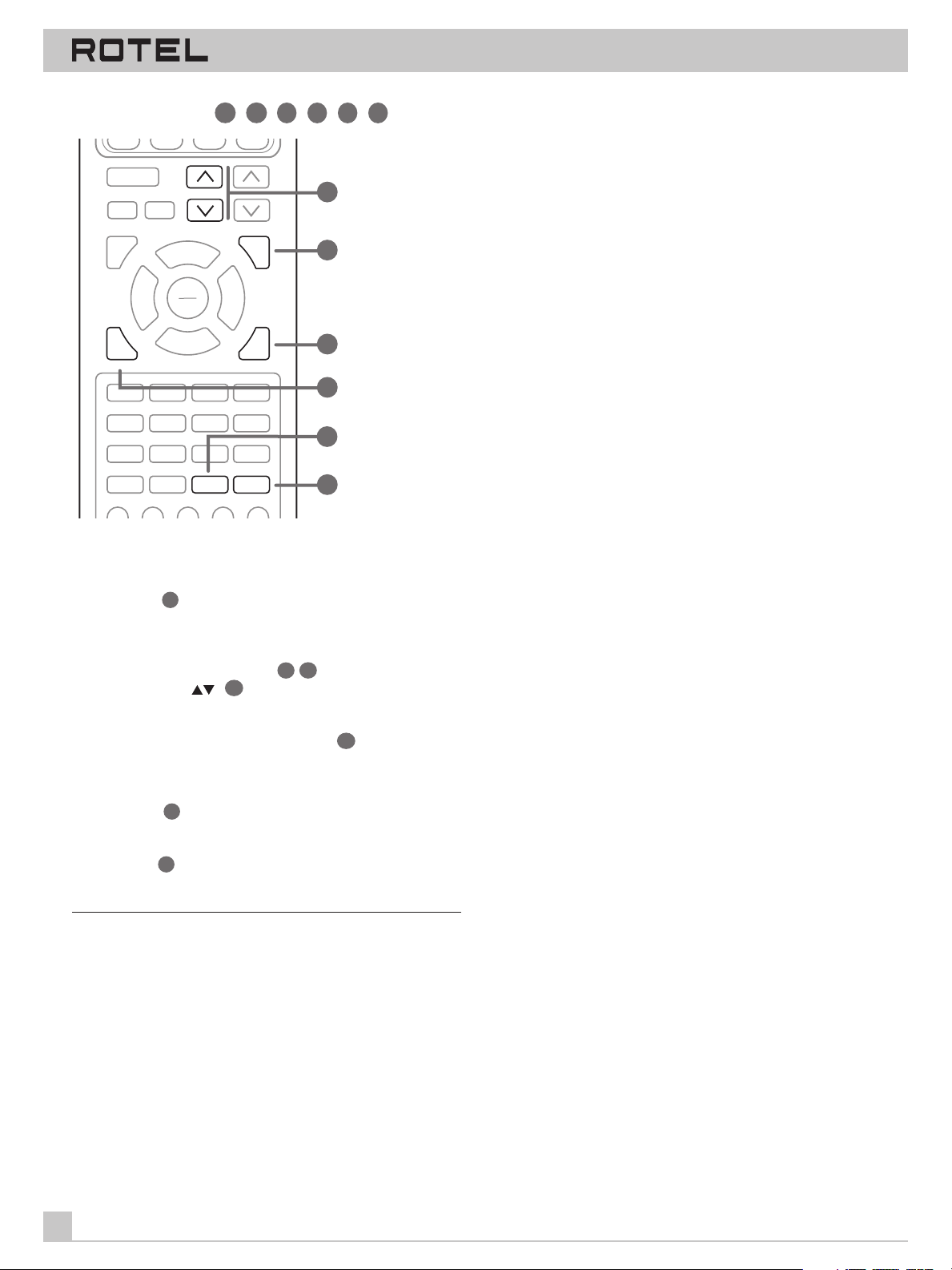
The following buttons are used to navigate the ON-SCREEN MENU
system:
MENU Button:
49
To display the MAIN screen. All other menus
are reached from this menu. If a menu is already visible, push this
button to cancel the Display.
50
DOWN/UP remote control buttons
front panel buttons (
) 5: To move up and down in the lists
46
or NUMERIC Keypad
that appear on the ON-SCREEN MENU system.
VOLUME DOWN/UP remote control Buttons:
41
To change the
current settings for a selected menu choice on some menus in the
ON-SCREEN MENU system.
ENTER Button:
53
To toggle through available settings for a se-
lected menu choice on some menus.
BACK Button:
on an ON-SCREEN MENU and return to the previous menu.
52
The BACK button is used to cancel a selection
Note: There is no need to memorize these buttons. A brief help
20
Page 21
RTC-965
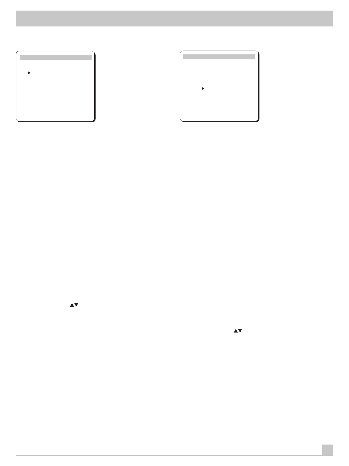
INPUT SELECTOR Menu
INPUT SELECTOR
Video: DVD
Audio: TUNER
Video REC: DVD
Audio REC: TUNER
5.1Ch Input: OFF
Input Source: AUTO
DOWN–selection ENTER–change
BACK-return MENU-screen off
The INPUT SELECTOR menu provides status information and configuration options for the source inputs. This screen is available
from the MAIN menu. The screen displays the following status information:
VIDEO: the currently selected video source
AUDIO: the currently selected audio source
VIDEO REC: the currently selected source for VIDEO 1 REC outputs
AUDIO REC: the currently selected source for audio recording,
cannot be independently changed
5.1 CH INPUT: whether or not the 5.1 channel input is active
INPUT SOURCE: AUTO or ANALOG. With the AUTO setting (the
factory default), the selected input source will check first to see if
there is a signal present at the digital inputs. If so, it will play the
digital signal, automatically activating DOLBY DIGITAL or DTS surround processing depending on the source. If no digital signal is
present, the analog inputs will be automatically enabled for that
source. With the ANALOG setting, the automatic sensing is disabled and the system will always revert to the analog inputs. A
digital signal will be ignored even if present and there will be no
DOLBY DIGITAL or DTS processing. Generally, this setting should
be left in the default AUTO mode unless you wish to override the
digital inputs for some reason.
Change any setting by moving the cursor to the desired line using
the UP/DOWN buttons on the remote or the NUMERIC Keypad
front panel buttons (
tons. Return to the MAIN menu by pressing the BACK button. Turn
off the ON-SCREEN DISPLAY by pressing MENU.
), adjust the setting using the ENTER but-
SURROUND MODE Menu
SURROUND MODE
Mode: DOLBY PRO LOGIC
Delay Time
CENTER: ____
REAR: 20ms
BASS LEVEL: +10dB
DOWN–select ENTER/VOL–change
BACK-return MENU-screen off
The SURROUND MODE menu provides status information and
configuration options pertaining to the surround operation. This
screen is available from the MAIN menu. The screen displays the
following status information:
MODE: the currently selected surround sound mode (PRO LOGIC,
DSP, 3-STEREO, etc.) Remember that Dolby Digital and DTS are
automatically enabled based on source material encoding and,
therefore, no setting is required.
DELAY TIME (center): the current delay setting for the center
channel speaker; only available in Dolby Digital mode
DELAY TIME (rear): the current delay setting for the rear surround
speakers
BASS LEVEL: Increases or decreases the level of the bass information for the selected surround mode. You can set one bass level
for theater surround modes and one bass level for music modes
(DSP and STEREO). Unlike the front panel bass control, these settings are memorized and engaged automatically each time a music or theater surround mode is selected.
In many systems, the factory delay settings will be satisfactory.
However, delay times may need to be adjusted depending on the
relative distance from the listening position to the front and rear
speakers so that you do not hear, for example, an explosion in a
soundtrack start in the rear of the room instead of the front. Increase the relative delay to the rear speakers if they are located
closer to the seating area than the front speakers.
Change a setting by moving the cursor to the desired line using
the UP/DOWN buttons on the remote or the NUMERIC Keypad
front panel buttons (
mote button. Return to the MAIN menu by pressing the BACK button. Cancel the ON-SCREEN DISPLAY by pressing the MENU
button.
), adjust the setting using the ENTER re-
21
Page 22
SURROUND SOUND TUNER PREAMPLIFIER RTC-965
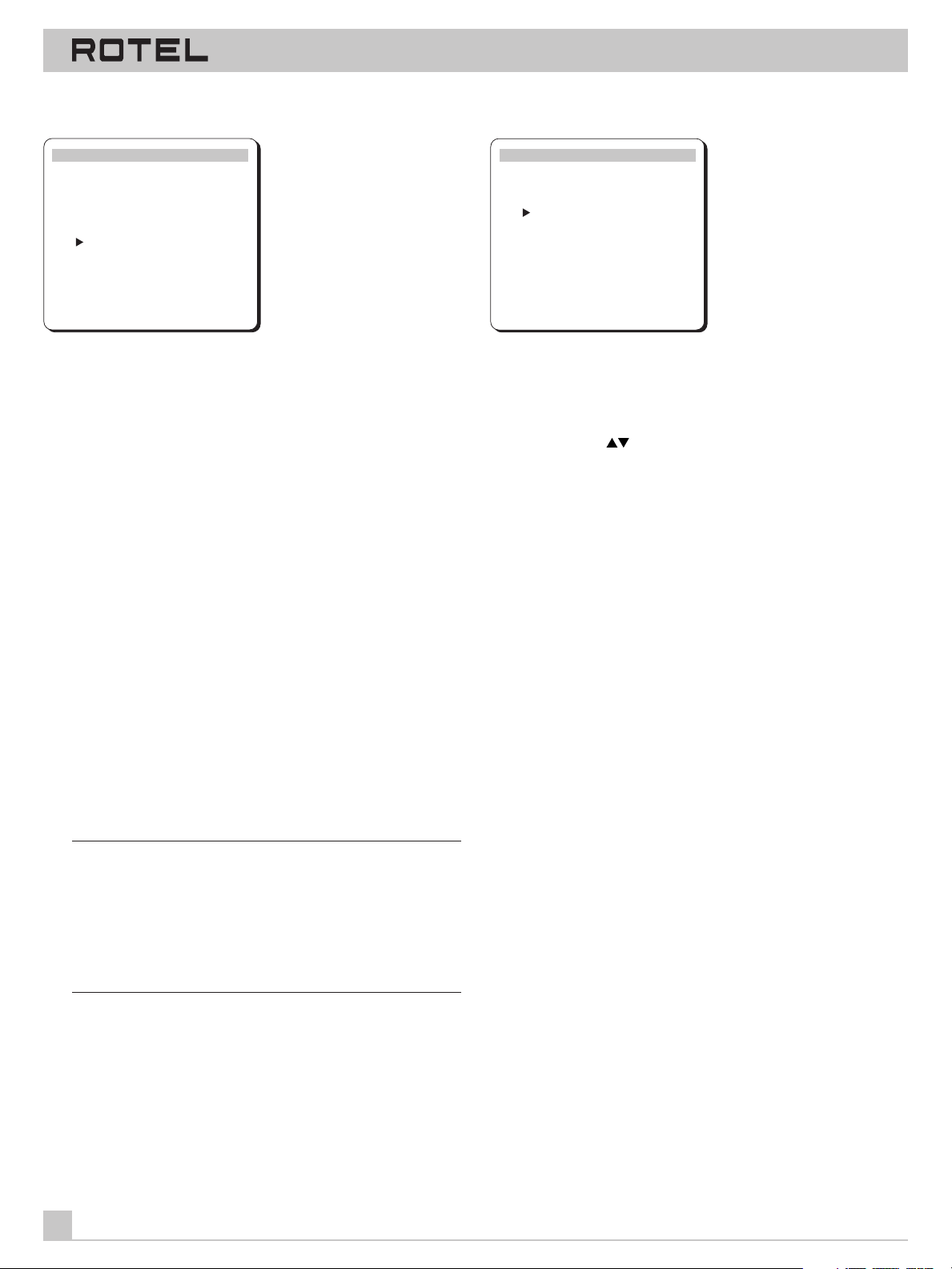
TEST TONE Menu
TEST TONE
Front - L
Center 0dB
Front - R
Rear - R 0dB
Rear - L -5dB
Subwoofer 0dB
DOWN–selection VOLUME–change
BACK-return MENU-screen off
This menu is used to set equal volume levels for all speakers
(front, center, rear, and subwoofer) for proper surround sound reproduction. To access this menu and perform the test tone calibration you must be in one of the surround modes. To do this,
press any of the MODE buttons except STEREO. Then, enter the
ON-SCREEN MENU system and select TEST TONE from the MAIN
menu to reach this screen.
When you enter the TEST TONE menu, you will hear a test tone
coming from the highlighted speaker. Highlight different speakers
by moving the cursor to the desired line using the UP/DOWN buttons on the remote. The test tone will shift accordingly to the selected speaker.
TONE/BALANCE Menu
TONE / BALANCE
Bass : +10dB
Treble : +10dB
Balance : L 10
DOWN–selection VOLUME–change
BACK-return MENU-screen off
This menu duplicates the functions of the front panel TREBLE,
BASS, and BALANCE controls and provides a method of changing
them with the remote control. Select a line in the menu using the
UP/DOWN buttons on the remote or the NUMERIC Keypad front
panel buttons (
DOWN remote buttons. Return to the MAIN menu by pressing the
BACK button. Cancel the ON-SCREEN DISPLAY by pressing
MENU.
), then adjust the setting using the VOL UP/
While seated in the normal listening location, switch the test tone
to the various speakers. Using the front speakers as a fixed reference (there is no adjustment for the front), listen to hear if the
center speaker or the rear speakers are noticeably louder or quieter than the front speakers. If so, adjust the speaker’s volume
levels up or down to match the front speakers using the VOL UP/
DOWN remote buttons. Continue switching among the speakers
and adjusting until the center speaker and both of the rear speakers sound as loud as the front speakers.
Return to the MAIN menu by pressing the BACK button. Cancel
the ON-SCREEN DISPLAY by pressing MENU.
Note to Perfectionists: This calibration will be more accurate if
you use a sound pressure level (SPL) meter to measure the output
of each speaker instead of relying on your ear. SPL meters are
available from electronics stores, or your authorized Rotel dealer
may loan you one. Set the meter to its SLOW response time with
C-weighting and be sure to hold it away from your body. The goal
is to adjust each speaker so that the meter provides the same
reading for each of the speakers in your system.
22
Page 23
RTC-965
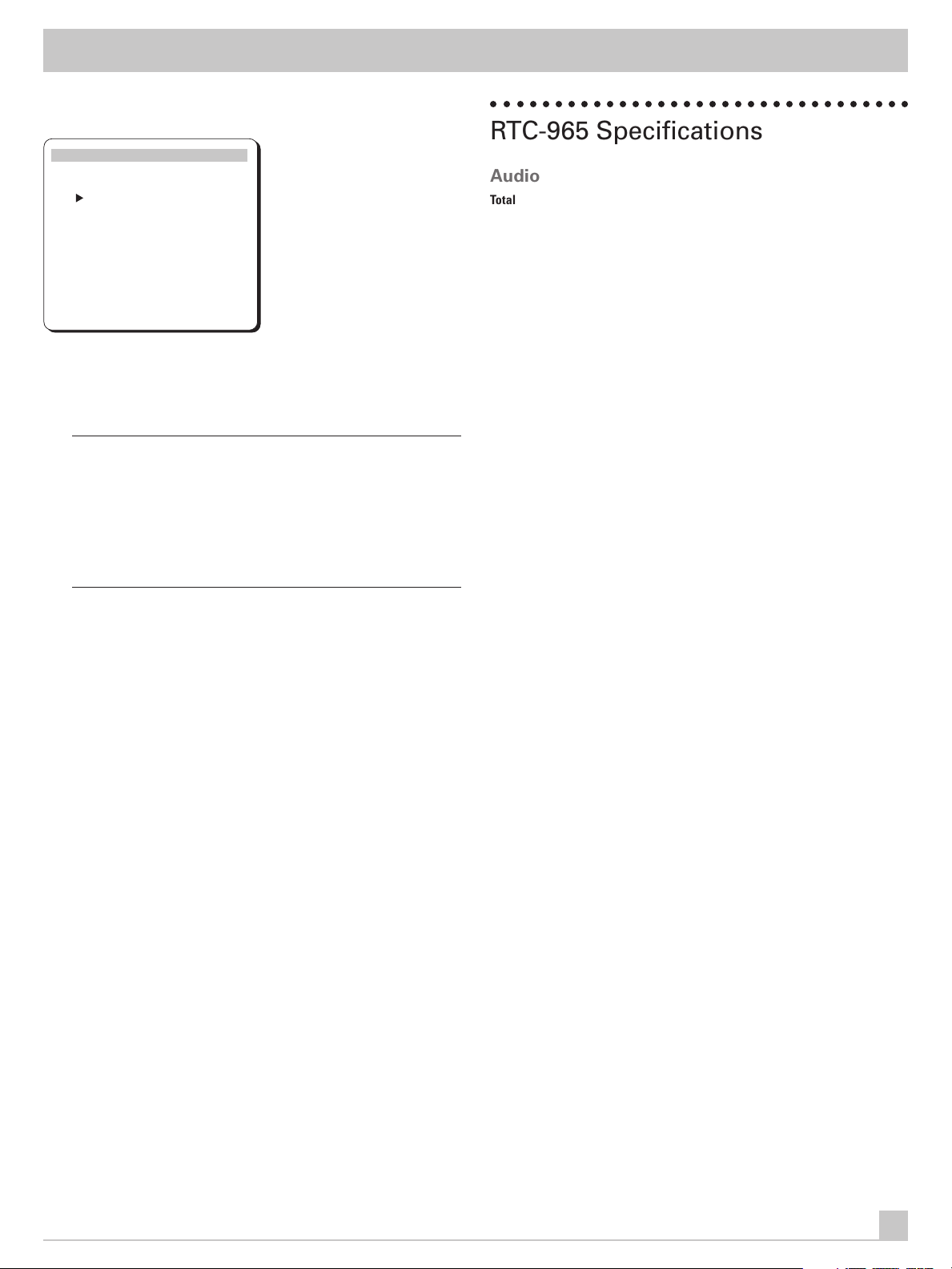
SETUP Menu
SETUP MENU
Front: LARGE
Rear: SMALL
Center: LARGE
Subwoofer: YES
Dynamic Range: OFF
Menu Display: SCREEN
DOWN–selection ENTER–change
BACK-return MENU-screen off
The SETUP menu provides status information and configuration
options for a variety of system parameters. Some of these settings
duplicate the function of front panel controls.
Note 1: See the discussion of speaker configuration under the
SPEAKER MODE button heading in the Front Panel Controls section of the manual. Detailed instructions for choosing speaker
types are presented there.
Note 2: Speaker configuration must be performed for each surround mode.
Note 3: Some options described below will not be available in
some surround modes and some system configurations.
FRONT: whether the front speakers are LARGE (full bass response) or SMALL (limited bass output)
REAR: whether the rear speakers are LARGE, SMALL, or NONE
CENTER: whether the center speaker is LARGE, SMALL, or NONE
SUBWOOFER: whether there is a subwoofer in the system: YES or
NO
DYNAMIC RANGE: whether the dynamic range compression is
turned OFF (full dynamic range/no compression), MID (moderate
dynamic range/moderate compression), or MIN (minimum dynamic range/maximum compression). Only available in Dolby Digital mode.
MENU DISPLAY: determines whether status information will appear on screen when volume, input, or other selections are made
– choices are SCREEN (display on) or OFF (display off).
Change any setting by moving the cursor to the desired line using
the UP/DOWN buttons on the remote, change the setting by
pressing the ENTER button to step through the choices. Return to
the MAIN menu by pressing the BACK button. Cancel the ONSCREEN DISPLAY by pressing MENU.
○○ ○○○○○○○○○○○○○○○○○○○○○○○○○○○○○○○
RTC-965 Specifications
Audio
Total Harmonic Distortion: <0.03%
Intermodulation Distortion (60 Hz: 7 kHz): <0.03%
Frequency Response (line level): 10 Hz - 70 kHz, ± 3 dB
Signal to Noise Ratio (IHF “A” weighted): 92 dB (Stereo)
70 dB (Dolby Digital)
Input Sensitivity/Impedance
Line Level: 200 mV/47 kohms
Phono Input: 3.5 mV/47 kohms
Tone Controls (Bass/Treble): ±8 dB at 100 Hz/10 kHz
Video
Frequency Response: 3 Hz-10 MHz, ± 3 dB
Signal to Noise Ratio: 45 dB
Input Impedance: 75 ohms
Output Impedance: 75 ohms
Output Level: 1 volt
FM Tuner
Usable Sensitivity: 14.2 dBf
Signal to Noise Ratio: 70 dBf
Harmonic Distortion: 0.3%
Stereo Separation (1 kHz): 45 dB
Output Level (mono): 550 mV, ± 100 mV
Antenna Input: 75 ohms unbalanced
AM Tuner
Sensitivity: 500 µV/m
Signal to Noise Ratio: 40 dBf
Output Level: 150 mV, ± 30 mV
Antenna Input: Loop Antenna
General
Power Consumption: 40 watts
Power Requirements (AC): 120 volts, 60 Hz (USA version)
230 volts, 50 Hz (European version)
Weight: 6.9 Kg/15.2 lb.
Dimensions (W x H x D): 450 x 158 x 303 mm
173/4" x 61/4" x 12"
All specifications are accurate at the time of printing.
Rotel reserves the right to make improvements without notice.
Rotel and the Rotel HiFi logo are registered trademarks of The Rotel Co, Ltd., Tokyo, Japan.
DTS is a registered trademark of Digital Theater Systems.
Manufactured under license from Dolby Laboratories Licensing Corporation. “Dolby”, “Pro Logic”, and
the double-D symbol are trademarks of Dolby Laboratories Licensing Corporation. Confidential unpublished works © 1992 – 1997 Dolby Laboratories, Inc. All rights reserved.
23
Page 24
RTC-965
SURROUND SOUND TUNER PREAMPLIFIER
The Rotel Co. Ltd.
10-10 Shinsen-Cho
Shibuya-Ku
Tokyo 150-0045
Japan
Phone: +81 3-5458-5325
Fax: +81 3-5458-5310
Rotel of America
54 Concord Street
North Reading, MA 01864-2699
USA
Phone: +1 978-664-3820
Fax: +1 978-664-4109
Rotel Europe
Meadow Road
Worthing, West Sussex BN11 2RX
England
Phone: +44 (0)1903 524 813
Fax: +44 (0)1903 524 831
Rotel Deutschland
Kleine Heide 12
D-33790 Halle/Westf.
Germany
Phone: +49 05201-87170
Fax: +49 05201-73370
082 OMRTC-965D 070799
 Loading...