

Page 1

Quality Uncompromised
®
Technical
DVD PLAYER
RDV-985
Manual
Table of Contents
Specification......................................1
Information........................................2~17
Block Diagrams.................................18~22
Schematic Diagram ..........................23~33
PCB Assembly..................................34~36
Parts List...........................................37~47
Specifications
General
Readable Discs: DVD VIDEO, Audio CD, VIDE CD, SUPER VIDEO CD
Video Fomat: PAL or NTSC selectable
Video Output
VIDEO OUT (pin jack): 1.0 Vp-p (75 ohms)
S-VIDEO OUT (S jack):
Y Output: 1.0 Vp-p (75 ohms)
C Output: 286 mVp-p (75 ohms)
Horizontal Resolution: 500 Lines
Signal to Noise Ratio: 65 dB
Audio Output
ANALOG OUT (pin jack): 2.0 Vrms (10 kohms)
DIGITAL OUT (optical): - 21 to -15 dBm (peak)
Audio Characteristics
Frequency Response:
CD: (sampling frequency 44.1 kHz): 2 Hz to 20 kHz
DVD (sampling frequency 48 kHz): 2 Hz to 22 kHz
DVD (sampling frequency 96 kHz): 2 Hz to 44 kHz
Dynamic Range:
16 bit: More than 100 dB
20 bit: More than 108 dB
24 bit: More than 108 dB
Wow and Flutter: Unmeasurable (less than
Total Harmonics Distortion: Less than 0.002%
Physical
Power Requirements:
USA Version: AC 120V, 60 Hz
European Version: AC 230V, 50 Hz
Power Consumption: 23 W (POWER ON), 2 W (STANBY mode)
Weight: 4.7 kg (10.4 lbs)
Dimensions (W x H x D): 445 x 112 x 338 mm
1/2 x 47/16 x 135/16 inch
17
±
0.002%)
THE ROTEL CO., LTD.
SHINSEN-BLD. 4F 10-10 SHINSEN-CHO, SHIBUYA-KU,
TOKYO 150-0045, JAPAN
Serial. NO.
Beginning
Y-356A-0109/W
Page 2
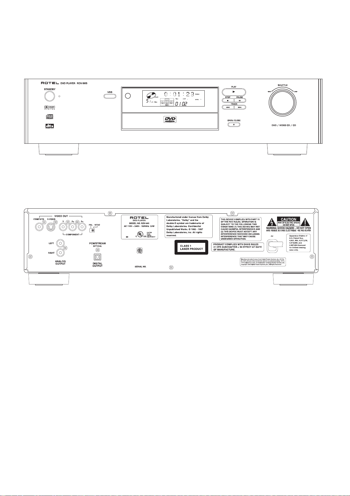
Appearance
2
Page 3
Main Adjustment
3
Adjustment and confirmation matter
(1) Auto adjustment method
If microprocessor (IC401, IC402, IC714, IC716) or servo board (LEA10047) is replaced, initialize
the D VD player in the following matter:
ref. separate sheet.
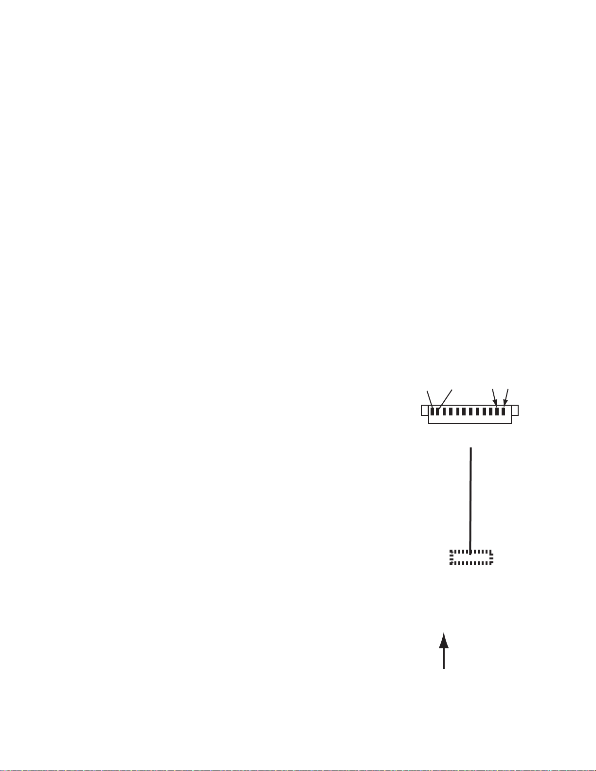
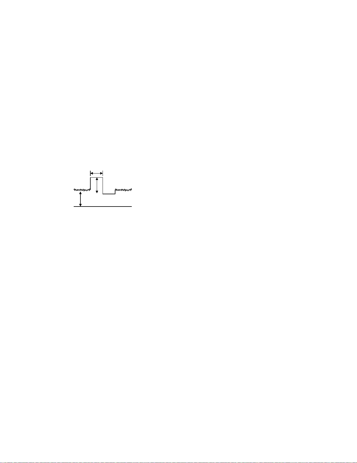
(2) Confirmation of DVD RF level
1.The oscilloscope is connected between "1"(RFOP) of
CN104 and "2"(GND).
2.Reproduction of the test disc ( VT-502)
made by JVC.
3.It is confirmed that RF LEVEL is 350mVp-p 150mVp-p.
4.When there is disorder in the waveform road cuts etc,
test disk is exchanged and measured.
+
-
(3) Confirmation of CD jitter level and RF level
1. The CD jitter meter is connected between "11"(GND)
of CN104 and "12"(FLTOUT).
The RF level is observed at the same time.
2.The first test disk(CTS-1000) made of JVC is reproduced.
3.It is confirmed that RF LEVEL is 360 100mVp-p.
5. When there is disorder in the waveform road cuts
etc, test disk is exchanged and measured.
+
-
GNDGNDFLTOUT
12 ~ 1
CN104
Servo control P.C.B
LEA20001
DVD SERVO CONTROL PWB
"1""2""11""12"
RFOP
FRONT SIDE
Page 4
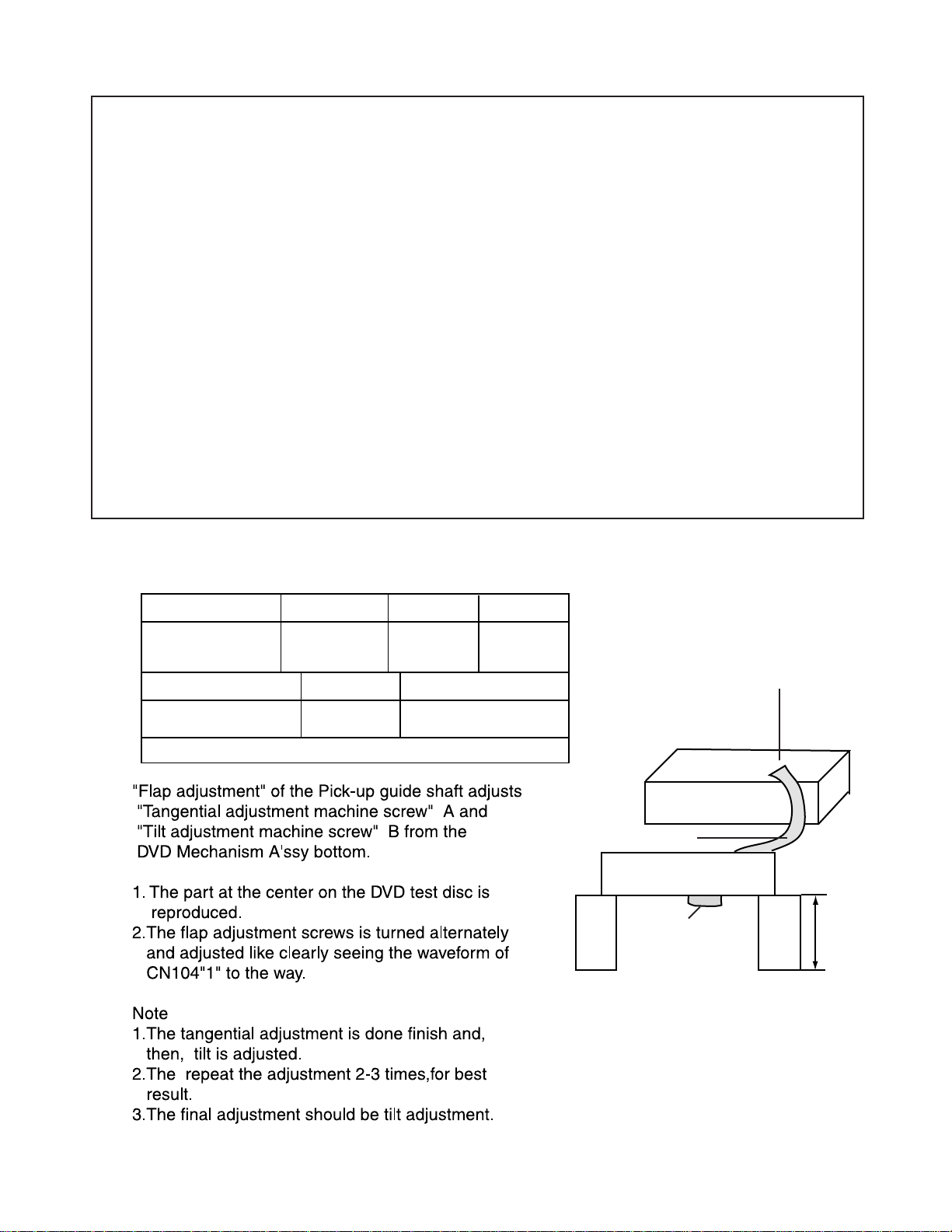
(4)Flap adjustment of the Pick-up guide shaft
4
Attention !!
RDV-985 is adjusted from issue machine because of the FL display on the way.
Please go in the adjustment method before changes according to the following procedures.
Measurement
CN104 pin"1"
GND:CN104 pin"2"
Measurement machine
Oscilloscope
General tool : Hex-head wrench(2mm)
Adjustment point
Refer to Fig.2
connections
Refer to Fig.1
Mode
Reproduction
part
Extension cord No.
QUQ110-3740AM
Disc
VT-502
Extension Cord
DVD Mechanism A'ssy
CN11 of
Stand
Connection PWB
CN101 of DVD Servo Control PWB
RDV-985
Stand
200mm
Fig.1
Page 5

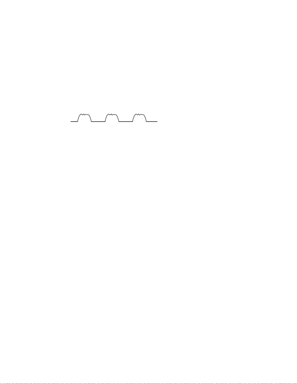
Confirmation after adjustment.
5
Confirm to reproduce video CD and CD after
the DVD test disc is adjusted and to find abnormality.
B
Fig.2
A
A
(5) About keeping the disc
As for the DVD test disc, plane accuracy is demanded.Please note the keeping place on the disc.
1. Please do not put the disc directly on the work desk etc. after uses .
2.T o keep the planarity of the disc, politely handle ,and please put in a special case and keep
the disc v ertically after uses .
Please k eep keeping the disc in a cool place where direct sunshine and the air-conditioning
wind do not dr ive.
3.When the disc cur ves,an accurate adjustment cannot be done.
Please e xchange for a new test disc and adjust optics.
4Other discs might not be ab le to be reproduced when adjusting on a curved disc.
Point of adjustment
* Please execute the static electricity protection measures before starting the
adjustment.
* When the following parts are exchanged,optical adjustment "Adjust the flap of the disc motor"
is necessary.
1.The disc motor w as exchanged.
2.The laser pic k up was exchanged.
3.The tr averse motor unit was exchanged.
Note
Additionally , please adjust the flap of the disc motor when the picture quality deterioration is
seen .The basic adjustment though, is unnecessar y for part exchange in the traverse.
An optical adjustment in the laser pick up cannot be done.
Please adjust the flap of the disc motor after e xchanging the laser pick up.
* When the traverse unit is exchanged, the adjustment is basically unnecessary.
Page 6
Check points for each error
6
(1) Spindle start error
*Defective spindle motor
Are there 10ohms resistance between each pin of CN101 "29~31"?
(The power supply is turned off and measured.)
*Hall element: Is sine wave output between CN101 "23" and "24", between "25" and "26",
and between "27" and "28" during rotation?
In either case, replace the mechanical unit.
*Defective spindle driver (IC251)
Is a driving wave output from CN101 "29~31" ?
During
rotation
Is IC251 "9" at "H" level (START)?
Servo IC --- Is control signal sent to the motor driver ?
IC201 "95" : Duty is 50% during stop, but varies during rotation (greatly varies at start).
--- If not sent, pattern or servo IC (IC201) is defective.
R259 : approx 2.5V during stop, but varies during rotation (greatly varies at start).
--- of not sent, pattern or servo IC (IC201) is defective.
Is FG input to servo IC ?
Observe FG wave from IC201 "89". --- If not output, pattern, IC251 or IC201 is defective.
(2) Disc Detection, Distinction error (no disc, no REFNV)
* Laser is defective.
* Front End Processor is defective (IC101).
* APC circuit is defective. --- Q101.
* Pattern is defective. --- Lines for CN101 "15" and "17".
Lines for between IC201 "2" and IC101 "2"(LDONA),
between IC201 "3" and IC101 "1" (LDONB).
* Servo IC is defective (IC201).
* Is signal sent to IC201(servo)"71" AS2 ?
* IC101 --- For signal from IC101 to IC301, is signal output from IC101 "88" (RFAS1) and
IC101 "69" REENV ?
Page 7
(3) Traverse movement NG
7
* For automatic adjustment, traverse movement occurs only when the position is changed to retry
judging the disc type after the 1st judgment resulted in an error. Therefore, traverse movement
rarely occurs because, in most cases, disc judgment at the current position (1st time judgment)
is executed successfully. (Of course, NG rarely occurs in this step.)
Note: 1st time judgment of disc type resulted in NG. --- The re-judgment of disc type may not be
successful. Therefore, after removing the cause of traverse movement, re-execute automatic
adjustment and confirm that no problem exists.
* Check point
a)During stop
Whether 50% duty pulse is output to R273
Whether between R274 and C271 is at approx. 2.5VDC
Offset voltage between CN101 "34" and "35" (scores mV if exists)
b)When tray is opened or closed
Check by oscilloscope whether a rectangular wave signal is output from CN101 "34" or "35".
50msec
2.5V
Approx.
500mV
GND
If checking a) or b) resulted in NG, IC201 maybe defective.
(4) Focus ON NG
* Is FE output ? --- Pattern, IC101
* Is FCDRV signal sent ? (R286) --- Pattern, IC301
* Is driving voltage sent ?
CN101 "20", "21" --- If NG, pattern, driver, mechanical unit (with the power turned off, measure the
resistance between CN101 "20" and "21").
* Does CN101 "7"(SRF1) become "H" and is the focus drawing in done?
--- Mechanical unit (laser power too low), IC101(defective gain)
--- Moreover, It is thought that abnormality is found in the disk.
* Mechanical unit is defective.
(5) Tracking ON NG
* When the tracking loop cannot be drawn in, IC201 "39" (/TRON) does not become "L".
* Mechanical unit is defective.
Because the under mentioned adjustment value is abnormal, it is not possible to draw in normally.
* Periphery of driver (IC271)
Constant or IC it self is def ective.
(When passing without becoming abnor mal while adjusting the following.)
* Servo IC (IC201)
When improper ly adjusted due to defective IC.
[F ocus position rough adjustment]
[Phase diff erence cancellation rough adjustment]
[T racking balance adjustment]
Page 8

(6) Spindle CLV NG
8
* When the spindle cannot be shifted to CLV Servo, does not become "H" between IC301 "69"
and IC201"37".
* IC201 Is signal output from CN103 "1" (RFOP)?
* IC201 Is signal output from CN103 "11" (DSLIP)?
* IC201 Is signal output from CN103 "6" to "9" (binary-coded clock and data)?
* IC201 Is "39" (/TRON) at "L" level ?
* IC301 "74" to "76" --- Is signal output to IC201 "24", "25", "28" (In case of only CD).
(Serial communication of rotation information)
* Spindle motor driver is defective.
Even when one of the three phases is defective, item (1) may be passed.
--- Check the second item in (1) above.
* C260 to C263 Defective soldering
If noise eliminating capacitors are not properly soldered, noise may ride on the waveform.
* Besides, the undermentioned cause is thought though specific of the cause is difficult because various
factors are thought.
Mechanism is defective.(jitter)
IC101, IC201.
(7) Address read NG
* Besides, the undermentioned cause is thought though specific of the cause is difficult because various
factors are thought.
Mechanism is defective. (jitter)
IC201, IC301, IC401.
The disc is dirty or the wound has adhered.
(8) Between layers jump NG (double-layer disc only)
* When the focus flight is generated when jumps between layers.
Because all adjustments for L1 layer must be successful, this error may rarely be due to a
circuit defect.
* Crosstalk might occur from tracking to focus system. (See (11) ) --- Replace the mechanical unit.
* Driver surroundings.
* Defect of constant and IC.
* For double-layer discs, after checking CLV on layer L1, jumps to layer L0 after mode changes to FG.
Then tracking is turned off, and adjustments are executed from the focus position coarse adjustment
in order.
* When the jump between layers is done on the single-layer disk, the disk distinction error is thought.
--- The laser power is low (RF level is confirmed by CN102 "1" (RFOP)).
--- AS1, AS2, REFNV Is the signal sent to between IC101 and IC201 ?
Page 9
(9) Neither picture nor sound is output
9
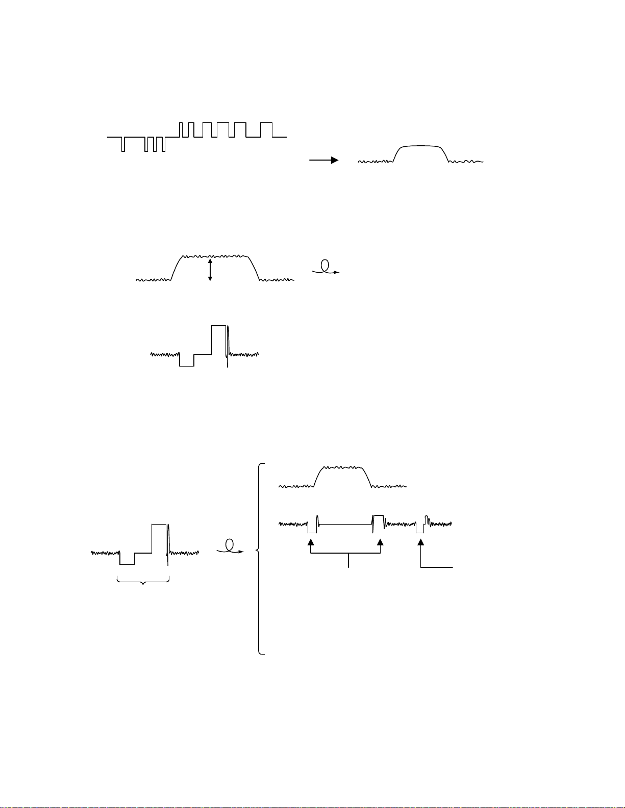
* Cannot search
a) Can the feed system be driven?
Chec k the waveform of TRSDRV signal (R273). --- Waveform between R274 and C271.
Search results in a change of duty
(three v alues with 2.5V at the center)
(The figure is e xaggerated.)
Chec k the waveform of CN101 "1" and "2". --- After the driver (IC271)
Approx.
2.5V
For short-distance search, the waveform
becomes roundish, not trapezoidal, and
voltage is low.
b) Is kick available?
Chec k the TRDRV signal waveform from R289.
Chec k the waveform of CN101 "22" and "23" --- After the driver (IC271)
Although diff ers in amplitude and DC offset, the waveform is similar to that of R289
Long-distance seek
Feed
Tracking
Kick pulse (fine seek) is
inserted after longdistance seek.
(Not one)
Kick pulse
Acceleration pulse at start;
deceleration pulse at stop
(each one)
(In the direction of search,
opposite to this figure)
Hold (DC) during feed
Page 10
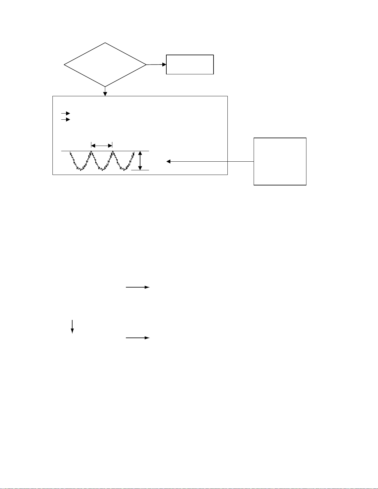
(10) Picture is distorted or abnormal sound occurs at intervals of several seconds.
10
Does JITOUT
change periodically?
(2V or more in peak
value, except
during kick)
YES
Feed system is defective (drive gain is defective: too large).
Check the waveform according to a) in (9).
Play back a simple disc with no angle change.
OK when the following waveform appears at intervals
of several seconds.
5~10Sec.
1~1.2V
Some system other
NO
than servo may be
defective.
If this voltage is too
high (2V or more, for
example), feed motor
may be defective, or
the mechanical unit
has seized.
(11) Others (unusual events experienced to date)
* Problem occurs with double-layer discs although no problem occurs with single-layer DVD.
(Error occurs, or search becomes unstable and takes longer.)
Crosstalk might occur from tracking to focus system.
--- When FE was observed during search (skip, etc.), it was found that a wave resembling TE
with an amplitude of 200mVp-p was riding on FE.
--- Mechanical unit was replaced.
* Error frequently occurred in the outer part of discs although no error occurred in the inner part.
--- Mechanical unit was replaced because tilt seemed to be defective.
(12) CD During normal playback operation
a) Is TOC reading normal?
NO
Please refer to "Servo Volume" flow.
Displays total time
for CD-DA.
Shifts to double-speed
mode for V-CD.
b)Playback possible?
YES
NO
*--:-- is displayed during FL serch.
According to [*Cannot serch ] for DVD(9), check the feed
and tracking systems.
*No sound is output although the time is displayed.(CA-DA)
*DAC, etc, other than servo.
*The passage of time is not stable, or picture is abnormal.(V-CD)
*The wound of the disc and dirt are confirmed.
(13) Others
V-CD : Frequent occurrence of error in inside and outer.
(Even the disk without the wound : when generated.)
Waveform observation
--- Is the oscillation frequency of about 700~900Hz output?
(Borrow a pertinent disk for the complaint for the combination with the disk.)
--- Exchanges mechanism for the mechanism resonance.
Page 11
Precautions for Service
11
Handling of Traverse Unit and Laser Pickup
1. Do not touch any peripheral element of the pickup or the actuator.
2. The traverse unit and the pickup are precision devices and therefore must not be subjected to
strong shoc k.
3. Do not use a tester to examine the laser diode. (The diode can easily be destroyed by the
inter nal power supply of the tester.)
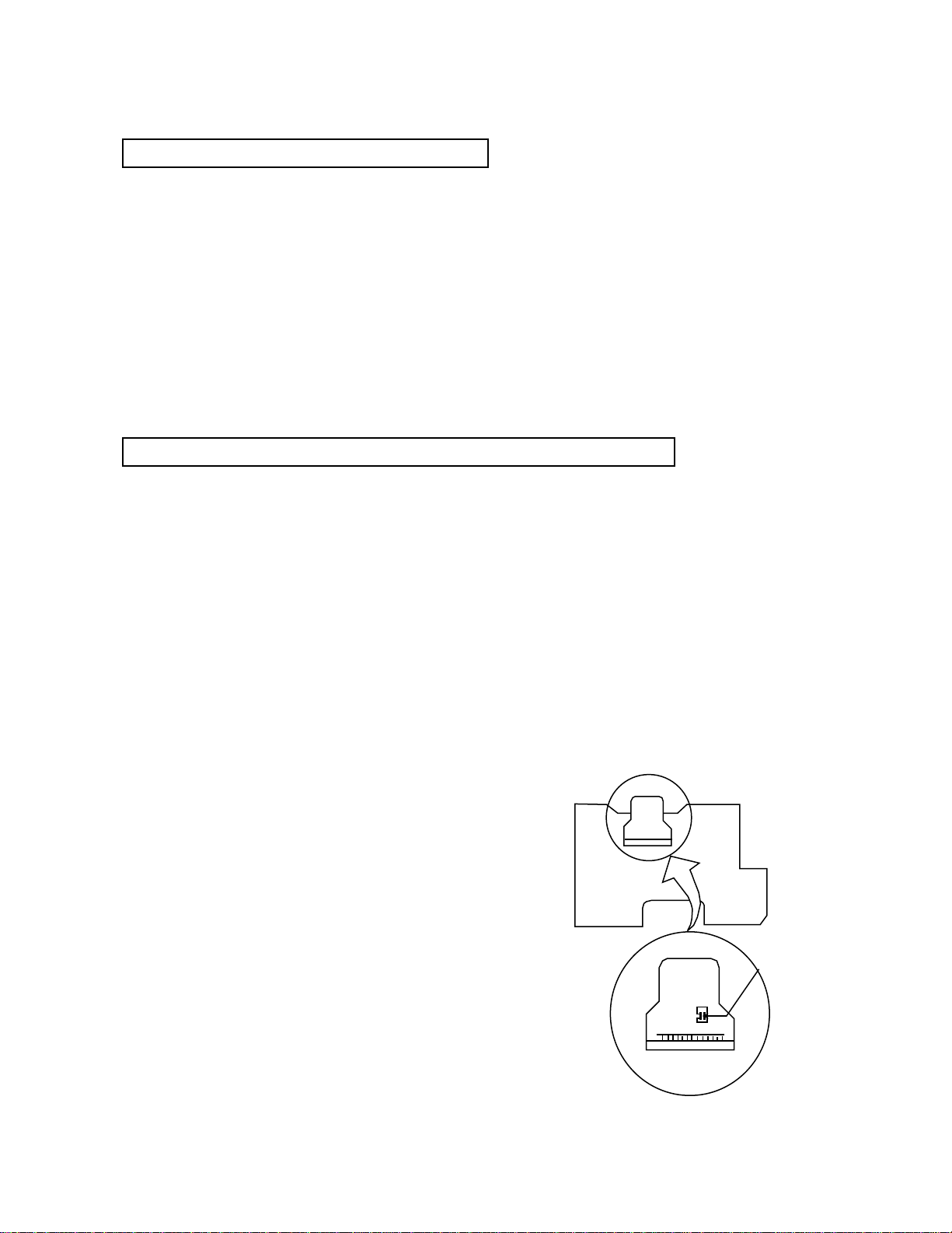
4. To replace the traverse unit, pull out the metal short pin for protection from charging.
5. When replacing the pickup, after mounting a new pickup, remove the solder on the short land
which is pro vided at the center of the flexible wire to open the circuit.
6. Half-fixed resistors for laser power adjustment are adjusted in pairs at shipment to match the
char acteristics of the optical block.
Do not change the setting of these half-fix ed resistors for laser power adjustment.
Destruction of Traverse Unit and Laser Pickup by Static Electricity
Laser diodes are easily destroyed by static electricity charged on clothing
or the human body . Before repairing peripheral elements of the traverse
unit or pic kup, be sure to take the following electrostatic protection:
1. Wear an antistatic wrist wrap.
2. With a conductive sheet or a steel plate on the workbench on which
the traverse unit or the pick up is to be repaired, ground the sheet
or the plate.
3. After removing the flexible wire from the connector (CN101),
short-circuit the flexible wire by the metal clip.
4. Short-circuit the laser diode by soldering the land which is provided
at the center of the flexible wire for the pickup.
After completing the repair , remove the solder
to open the circuit.
Short-circuit
Page 12
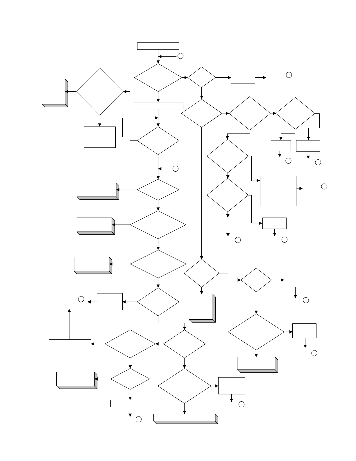
Troubleshooting
1.Power-on processing
12
Connect to outlet.
A
to
Micro-
computer
Volume.
NO
POWER switch of
processing is OK.
to Power Supply
Does
the lamp
goes out when
remote control
box is turned
ON?
YES
Check S867
(power switch)
and the line
to IC714.
Power-on
Volume.
P.STAND-BY
indicating lamp
Press POWER switch.
NO
indicating lamp
YES
NO
voltage applied at each
lights up?
YES
STANDBY
goes out?
Does FL
light up?
NO
Correct
lead
of FL?
YES
NO YES
fuse is blown
IC953"1" at
approx.5.6V?
YES
B
F901
Voltage of
YES
Replace
F901.
NO
NO
wave detected on
the anode side of
Does the
oscillation wave
come out to
IC901"3"?
NO
Does the
DC voltage(input
AC 1.4V) come out to
D901 output side
NO
Replace
D901.
Return to A
and recheck.
Is the AC
D953?
NO
YES
YES
Return to A
and recheck.
YES
Connecting wires
to the soldered
part of the pins of
T902(transformer)
and anode of T902
is examined.
Replace
Return to A
and recheck.
Is energizing
of "cathode of D953"
and "pin1 of IC953"
YES
Replace
D953.
Return to A
and recheck.
IC901.
normal?
NO
Repair the
wiring.
Return to A
and recheck.
Return to A
and recheck.
to Power Supply
Return to B
and recheck.
Repair the wiring.
To Microcomputer
Volume.
Volume.
Check
IC831,R843
and C833.
between IC831"13"
and IC714"76" OK?
NO
NO
NO
Is connection
YES
Voltage
of CN831"19"
at +5V?
YES
Replace IC831.
Return to B
and recheck
Correct voltage
applied to IC831
(FL driver)?
YES
Oscillating
wave output from
IC831"20"?
YES
NONO
of IC831"14"-"16" and
IC714"2" to "4" OK?
To Microcomputer Volume.
of IC953"3"
computer
Voltage
of IC831"13"
(P.ON RESET)
at +5V?
YES
Is connection
YES
Voltage
at 5 V?
to
Micro-
Volume.
YES
NO
NO
OK between IC953"3"
Repair the
wiring.
Return to B
and recheck.
Is IC953
hot?
YES
Continuity
and IC714"16",
"62" and "99"?
OK
To Microcomputer
Volume.
NO
NG
Replace
IC953.
Return to A
and recheck.
Repair the
wiring.
Return to A
and recheck.
Page 13
2. Power Supply Volume
13
With all the wiring removed, check unit power board.
(1) Remove all flat wires and wire assemblies which are connected to CN801, CN805, CN806.
(2) Short -circuit CN805"4" (POWER ON:B168) and "5" (B5V:B167). (Set each regulator to ON.)
(3)
The load resistance is connected between CN805"5"(B5V:B167) and "8,9"(D.GND:B164).
(4) Connect to the outlet and check the voltage at each part.
(For the voltage specification, see the wiring diagram.)
* If the load resistance is not connected, the voltage is not output to "B167".
Then restore the connection of CN801, CN805, CN806 and check voltage.
(1) Remove the wire short -circuiting CN805"4" and "5".
(2) Remove the load resistance.
(3) Restore the connection of CN801, CN805, CN806.
(4) Connect to the outlet.
(5) Turn the POWER switch on and check the voltage at each part.
If voltage abnormally drops when CN801, CN805, CN806 are connected (load is connected) though the voltage
was at the normal level when CN801, CN805, CN806 were disconnected(load is connected), or if the protective
element (fuse, etc.) is opened, the load which is supplied power may be defective or the wiring may be
short-circuited.
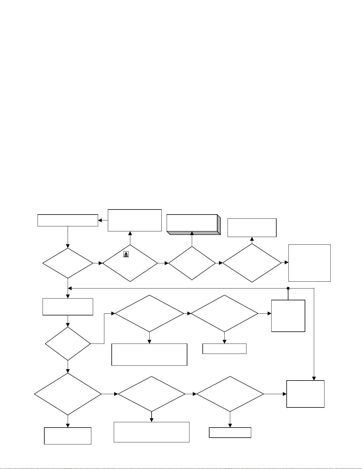
3. Open/Close Operation
Press OPEN/CLOSE key
Does the tray
smoothly open?
YES
Press in by hand
when fully opened.
Ejected
Does the tray
retreat?
YES
Voltage
between CN102"4"
and "5" at 0V when
tray ends
retreating?
OPEN/CLOSE
operation is OK.
NO
NO
Check S835 (OPEN/
CLOSE) and the
wiring to IC714.
YES
of
the remote control
box functions
normally?
CN102"1" at 0V when
tray opening operation
Check the connection between
CN102 and mechanical unit.
Check the mechanical unit.
CN102"3" at 0V when
Check the connection between
CN102 and mechanical unit.
Check the mechanical unit.
NO
Voltage of
ends?
NO
Voltage of
tray closing
ends?
NO
To Microcomputer
Volume.
NO
Voltage
of IC401"52"
at 0V?
YES
YES
IC401"52" at 0V when
tray opening operation
Check IC251 and
the periphery.
YES
Voltage of
Replace IC401.
IC401"51" at 0V when
tray closing
Replace IC401
voltage applied
between CN102"4"
and "5"?
ends?
YES
Voltage of
ends?
YESYES
Any
NO
NO
YES
Check the
connection
of CN102"1"
and
IC401"52"
NO
Check the
connection
between CN102
and mechanical
unit. Check the
mechanical unit.
Check the
connection of
CN102"3" and
IC401"51".
Page 14

4. Microcomputer Volume
14
Processing of Each Microcomputer
* IC714 System microcomputer (sub-microcomputer)
After powering on, this microcomputer is continuously activated to control keys and remote control
signals.
According to key operations or remote control signals, it controls (turns on/off) the power for
LSIs including IC401 (main microcomputer) and the audio/video output circuit.
It also controls the resetting of the main microcomputer, FL driver IC (IC831) for FL display, and
various LED displays.
* IC401 Main microcomputer
This microcomputer controls a group of LSIs of servo and signal processing sections according to
commands from the system microcomputer.
After receiving time information from the signal processing section, it transmits the information
together with the status to the system microcomputer.
It controls the resetting of the LSIs of the servo and signal processing sections.
It has IC402 (16Mbit ROM) as an external ROM.
Normal Starting Conditions
* IC714 System microcomputer
(1) +5V must be applied to "16" and "62".
(2) Oscillators of "13" and "15" must be oscillating correctly.
(3) Input to "12" (RESET) must be at +5V (reset cancel).
If above (1) to (3) are not satisfied when the P.STANDBY indicating lamp does not light at
power-on, IC714 may be defective.
* IC401 Main microcomputer
(1) +5V must be applied to "17","22","34","54","66"
(2) Clock signal (13.5MHz) must be input to "23" from IC301 (ODC LSI).
(3) Input to "82" (RST) must be at +5V (reset cancel).
(4) Communication line with IC714 ("57","58,"67"~"69") and that with IC402 (external ROM)
("13"~"16","26"~"33","35"~"42","44","93"~"100") must work normally.
If above (1) to (3) are not satisfied when the P.STANDBY indicating lamp goes out but FL does not
light when the POWER switch is turned on, IC401, IC714 or IC402 may be defective.
Page 15

5. Audio Volume
15
CN704 is
checked
IC850
Q851,Q852
is checked
YES
Is sound
output from
headphone?
YES
OK
The position of
the screw
fastening the
front panel is
confirmed.
This screw : because
there is working
of the ground.
Power
supplied correctly
to each IC?
YES
Is sound
signal output
from J702 (pin
jack)?
NO
Is sound
output from
headphone?
YES
Check Q711,
Q712 and J702
(soldered part).
NO
*
NO NONO
to Power Supply
Volume
IC702 are supplied
power from IC718.
Check I/O voltage of IC718.
Approx
. 5V
Voltage of
Q708 collector at
-12V?
YES
IC714 is
checked
Is
digital signal
output from
IC702"7"?
YES
Is
digital signal output
from IC701"20"?
YES
Is digital
signal output from
IC702"10", "13", "16"
and "19"?
YES
Check IC703, IC704
and their periphery.
NO
NO
NO
Check IC702
and PLL.
Replace
IC701.
Replace
IC702.
* PLL normal lock voltage
Between TP701 and TP702.
When fs=44.1kHz
When fs=48kHz
When fs=96kHz
0.6V
0.9V
2.6V
* Changing over the cutoff frequency of analog LPF
When fs=44.1kHz or 48kHz,
Microcomputer port FS2 is at the "L" level,
and Q703 and Q704 are turned ON.
When fs=96kHz,
Microcomputer port FS2 is at the "H" level,
and Q703 and Q704 are turned OFF.
Page 16

6. Video Volume
16
Power
supplied correctly
to each IC?
YES
Is video
signal output from
J602 S terminal?
NO
Is signal
output from CN601"4"
YES
Check L603
L604,IC611
NO
to Power Supply
Volume
* +5V power for video section is
supplied from IC654.
Check I/O voltage of IC654.
YES
NO
?
Is video
signal output from
J603 composite
terminal?
YES
OK
Check the insertion of
NO
IC621,IC622,L604
L603,CN601
Is clock
signal input to
IC551"9"?
YES
Is digital
signal output from
IC551"1" to"8", "10" and
"11"?
YES
NO
NO
Check
IC501.
Check
IC501.
Service tips
*
(1) The disc playback screen is in the normal condition but graphics in the "ON SCREEN"
mode are abnormal => Replace IC553.
(2) Only 1/4 compressed playback screen of DVD or video-CD is abnormal => Replace IC552.
Signal flow of DISC media
DISC
IC101
FEP
IC301
ODC
IC501
AV DEC.
Check
IC551.
VIDEO
CIRCUIT
IC702
DAC
VIDEO
LPF
AUDIO
Page 17

7.Servo volume
17
Press
"OPEN/CLOSE"
key
Is the opening
operation of
TRAY normal?
Y
After "FL" displays
"Close", is "Reading"
displayed?
Y
Does the DISC
rotate ?
Y
Does pick-up
lens move up
and down?
Y
Does the
displayed in FL
is "NO DISC"?
N
Is drawing in
FOCUS normal ?
to OPEN/CLOSE
N
Operation Section
N
N
(1)Spindle start error
N
Does CN101"4"
(SWTRV) become 0V ?
Y
(3) Traverse
moving NG
Y
(2) Disc detection,
Distinction error
from A
*only two layer
disc (DVD)
Is the jump between
layers OK?
N
(16) Jump between
FE
layers NG
LO LI
Y
Was information on
N
the disk obtained?
(In case of NG, disc
(15) Address
read NG
eject at tray open.)
Y
N
N
Can you reproduce ?
(9) Checkpoint
according to error
Y
OK !
FE
OFF
ON
(It is NG when
tick tack retrying.)
Y
Is drawing in
TRACKING normal ?
TE
OFF
ON
Does IC201"39"
(/TRON) become "L" ?
Y
Is the shift to
spindle CLV OK ?
Does IC201"37"
(PLLOK) become "H" ?
Y
to A
N
(4) Focus ON NG
N
(8) Tracking ON NG
N
(14)Spindle CLV NG
Page 18

Block diagrams (DVD SERVO CONTROL Section)
18
FROM
CN601
OF
LVA10054-A2
(VIDEO &
648
CN503
JACK)
10
1
~ ~
11
151921
CN502
TO
10
CN701
OF
LVA10054-A1
31
32
(CPU)
378
1
33
Y OUT
C OUT
Pb OUT
IC554
VIDEO ENCODER
12, 14
V5V
OSC
X371
33.86MHz
IC371,IC372
1
IC374
CLK169
TC7WH74FU-X
13, 28
47~50
FEP
(Front End Processor)
LVA10047
BLANK
Pr OUT
39~46
MC44724AVFU
3, 46, 7
VREF
TC7SH04FU
ODC
99
ERROR
STATES
SIGNALS
CONTROL
20, 21
68
IC101
AN8706FHQ
LD
PHOTO DETECTORS
IC552
2M FRAM
IC555
+2.5 REG.
MC33269D
CPU DATAS
27
59, 60
UPD42280GU-30
WAITODC
OR GATE
AND GATE
IC301
108
MN103005ANZG
(Optical Disc Controller)
FG
ST/SP
9
16
111
FC
IC251
25, 27
AN8485SB
SPINDLE DRIVER
2~7
22, 26,28
CN101
15,27
16~23 36
(MN4777AS-XE)
FRD 0~7
FWD 0~7
GRAPHIC CONTROLLER
WAIT
IC311,IC312
TC7SH08FU
TC7SH32FU
45
IC201
ADSC
91, 93
14, 99
Servo Controller)
(Advanced Digital
11
CONTROL
9, 104,105
9, 20
23, 26
TRVSW
15~18
4CH DRIVER
FEED +/-
M +/-
11, 12
ACTT+/-
95~100
CA 0~19
CO 0~7
1~ 8
10, 11
IC551
JCE8011
9 25
STREAM DATAS . CD DA DATAS
IC321,IC322
TC7WH74FU
TC74VHC00FT
28
MN67705EA
12,13 35, 38 35, 38
SIGNALS
19,18
IC271
BA5983FM
13, 14
ACTF+/-
43
8M ROM
WAITDEC
CLK338
TOPEN
IC553
HSYNC
TCLOSE
DA DATA1
JCE8038-X
VSYNC
VD 0~7
13
OSC.
TRAY IN / TRAY OUT
CN102
DA LRCK
DA BCK
163,172,173
AV DECODER
15
178
IC502
27MHZ
NAXO265-001X
118
71, 76
51, 52
2
70,72
CPSCK
SDOUT
159
IC501
ZIVA3-PA1
8~11
2~4,6
1
3
CLK135
LSI RST
82
23
IC401
UNIT CPU
23
9,10
X401
CRYSTAL
16M SDRAM
16M SDRAM
IC507
TC7WH74FU
5
WAIT
CPU DATAS
1
IC402
16M ROM
MN102LP25G
7
13.5MHz
IC505
D4516161AG5-A10
(MN45V17160BT-10)
(KM41651020CTG10)
IC504
D4516161AG5-A10
(MN45V17160BT-10)
(KM41651020CTG10)
CSDEC
CPU DATAS
POWER ON
M27C1602CZ
M9V
D3.3V
D5V
652
CN501
8
LASER
PICK-UP
MOTOR
SPINDLE
FEED
MOTOR
DIGITAL 5V
POWER ON
DIGITAL 3.3V
MOTOR DRIVE 9V
MOTOR
REST SW.
LOADING
OPEN/
CLOSE SW.
ELM-V002
ASSEMBLY
DVD MECHANISM
OF
LVA10053-A1
FROM CN805
(Power Supply)
Page 19

Block diagrams (DC REGURATOR Section)
19
B5V
D5V
P.ON
D3.3V
6
852
+3.3V REG.
4
IC951
PQ05RF2
M9V
FROM CN501 OF
RS/
2SC1740S/
Q964,Q965
2SB1565/EF/
CN806
-20V
Q951,Q952
FL ON/OFF
DTA144ESA-T
2SC2060/QR/,
F1F2-VDSP
B5V
1
2
345
-24V
4.9V
5.0V
-26.3V
Q962
-30V REG.
D5V
FROM FW831 OF
LVA10053-A2
D960
+5V REG.
D950
2SA933S/RS/
(DISPLAY)
3
1
IC953
LM2940CT-5.0
7
CN805
2
+5V REG.
1
LVA10047
(DVD SERVO
CONTROL 1)
V+12V
+12V
1
3
CN801
+12V REG.
Q953,Q954
2SB1565/EF/
ON/OFF
DTA114YS,
Q955,Q956
TDC144ESA
-12V
P.MUTE
5
FROM FW702 OF
6
Q964
-12V REG.
D961,D963
2SC1740S/RS/
Q957,Q958,
ON/OFF
LVA10054-A1
(CPU)
D962
DTC114YS,
DTA114ESA
2SC2394/EF/
Q959,Q960
D951
C960
AC-DC
LVA10053-A1
D952
AC-DC
C963,C964
14
15
16
1
D901
AC-DC
S1WB/A/60-4101
T901
LINE FILTER
QQR0894-001
L961
L952
D953
AC-DC
C965,C966
11
T902
QQS0028-001
TRANFORMER
5
D904
C914
AC-DC
4
IC901
SWITCHING
REGURATOR
L955
D954
AC-DC
C979,C997
9
7
10
D908
D910
AC-DC
1
STR-F6652
Q966
D972,D973
C965,C966
MUTE DETECTION
RS/
Q961
2SC1740S/
PC901
PC123F
FEED BACK
D956
AC-DC
L957
C982,C984
PC902
PC123F
MODE SW.
D957
AC-DC
L959
C987,C989
AC IN
Page 20

Bloc k dia grams (VIDEO OUT & A UDIO OUT)
20
TO CN702
LVA10047
(DVD SERVO
CONTROL 2)
VIDEO SIGNAL IN
CN601
2
10
8
4
6
Pr
Pb
C
LVA10054-A2
V5V
4MHz LPF
1
L601
QQR0712-001
4MHz LPF
1
L602
QQR0712-001
Y
L603
6MHz LPF
1
QQR0713-001
3.58MHz BPF
L604
QQR0714-001
3
3
8
5
3
1
NJM2268D
4
IC621
Y AMP
COMPOSITE AMP
NJM2268D
NJM2268D
IC622
Q672
IC601
Pr,Pb AMP
NJM2267D
8 8
1 5
Y
IC622
C AMP
(2/2)
C
58
(1/2)
41
J601
5
4
2
Pr
Pb
Y
J602
3
S-VIDEO
4
OUT
J602
COMPOSITE
VIDEO OUT
COMPONENT
VIDEO OUT
TO CN502 OF
LVA10047
(DVD SERVO
CONTROL 1)
IEC958
AUDIO DATA IN
TO CN502 OF
LVA10047
(DVD SERVO
CONTROL 1)
CN701
1
4
2
DIN
IC702
LPF
MN35503-X
OUT1D
OUT2D
13 2
16
2
1
IC703
LPF
NJM4580L
1
IC704
LPF
NJM4580L
5
7
5
7
LVA10054-A1
J706
1
J702
OPTICAL
DIGTAL OUT
GP1F32T
Lch
AUDIO OUT
Rch
Page 21

TO CN831 OF
21
LVA10053-A2
(DISPLAY)
TO FW601 OF
A10054-A2
LV
(VIDEO & JA
TO CN801 OF
LVA10053-A1
(Power Supply)
Block diagrams (SYSTEM CONTROL & FL DRIVER Section)
CK)
CN703
1
4
7
15
5
16
CN702
2
6
9
19
20
CN701
19
20
21
33
4
1
7
8
+12V
DO1
IEC958
LRCK
BCK
KEY MATRIX
83,84,86~92
KEY MATRIX
83,84,86~92
REMO
SHUTTLE
VS1
VSD
SCK
RXD
TXD
POWER ON
KEY00~KEY03
KEYI0~KEYI5
KEY00~KEY03
KEYI0~KEYI5
19
REMO
95
SHUT1
46
VS1
47
VSD
SYSTEM CPU
IC714
M30622MC-736FP
7
OSDCK
5
OSDDO
6
OSDDI
11
POWER ON
RESET
XIN
EECS,
EECK,
EEDI,
EEDO
MUTE59FS2
71
12
15
27~30
3
4
2
LRCK
BCK
DIN
FS2
MN35503
RESET
IC717
1
RST
PST574CMT-X
OSC
X701
16MHz
PLL BLOCK
D701~D703,
L703
23
28
XIN
PDO
DAC
IC702
OUT1D
OUT2D
F.RESPONCE SW.
Q704~Q708
13
16
EEPROM
IC715
TC75H08F-X
CS
SKDIDO
123
4
LPF
IC703,IC704
NJM4580L
+5V
MUTE
LVA10054-A1
+5V REG.
IC718
3
OUT
IN
NJM78M05
+12V
+12V
-12V
P.MUTE
MUTE
Q708
Q711,Q712
DTA114ESA-T
2SD1302/ST/T
D706,D707
R OUT
L OUT
1
RDV-985
1
TO CN801 OF
LV
(POWER SUPPL
FW702
3
1
POWER
SUPPLY
5
6
J702
ANALOG
AUDIO OUT
OPTICAL
DIGITAL OUT
J706
GP1F32T
OPTICAL
DIGITAL OUT
A10053-A1
Y)
FROM CN703
OF LVA10054-A1
(CPU)
TO CN806 OF
LVA10053-A1
(CPU)
-VDSP
B5V
D5V
CN703
16
5
1
4
7
15
FW831
1
F1
2
F2
3
4
5
REMOTE CONTROL
~
SDATA,FLSCK,CS,POR
KEY MATRIX
~
KEY
MATRIX
S835,
S844~S848
SHUTTLE
RECEIVER
IC832
GP1U271X
1
REMO
13~16
FL DRIVER
QLF0049-001
1~3,108~109
IC831
M66004SP
FL DISPLAY
D1831
53~58
LVA10053-A4
D5V
LVA10053-A3
32
CN833
CN832
B5V
LVA10053-A2
1
1
3
3
6
~
~
6
SHUTTLE
S831
POWER
LED
D831
KEY
VSS S833
POWER S867
Page 22

Meno
22
Page 23

DVD Servo Control 1
DIGT
DIGT
AL D
AL D
AT
A SIGNAL
A SIGNAL
BLOCK A
BLOCK C
BLOCK B
BLOCK D
23
RDV-985
K371
22
47
Page 24

I
RDV-985 RDV-985
to Block C
to Block B
Block A
k A
24
Page 25

RDV-985
to Block A
to Block D
Block B
k B
25
Page 26

RDV-985
to Block D
to Block A
Block C
26
Page 27

RDV-985
DIGTAL DATA SIGNAL
to Block C
to Block B
Block D
27
Page 28

RDV-985 RDV-985
DVD Servo Control 2
ol 2
AUDIO SIGNAL
DIGTAL DATA SIGNAL
VIDEO SIGNAL
28
R549
HY57V161610DTC8
HY57V161610DTC8
Page 29

RDV-985
Display
29
VSS
Page 30

RDV-985
y
RDV-985
y
RDV-985
y
RDV-985
y
RDV-985
y
RDV-985
y
RDV-985
y
RDV-985
y
Power Supply
30
RDV-985
750K
750K
QNZ0136-001Z
QMF51U1-1R6-S
1000PF/AC250V
0.47(2W)
120uF/400V
LE40597-001A
4700PF/AC250V
68K(2W)
PC123F
Page 31

Video & Jac
31
RDV-985
AUDIO SIGNAL
VIDEO SIGNAL
Page 32

RDV-985
RDV-985
CPU
AUDIO SIGNAL
32
Page 33

2-53
Connection
33
RDV-985
Page 34

Printed circuit board
34
RDV-985
Display board
Power supply board
Page 35

CPU & Video & Jack board
35
RDV-985
S601
NTSC/PAL SW
Page 36

Servo control board
36
(BOTOM SIDE)
(TOP SIDE)
R374
Page 37

PARTS LIST
37
[RDV-985]
* All printed circuit boards and its assemblies are not available as service parts.
Page 38

Parts List 1/8
38
SYMBOL PARTS NO. DESCRIPTION SYMBOL PARTS NO. DESCRIPTION
POWER SUPPLY, FL DISPLAY BOARD LVA10053
BK901 E409182-001SM GRAND TERMINAL D844 1SS199-02-T2 SI DIODE
C832 QER61AM-476Z ELECTROLYTIC CAPACITOR 10V47uF D845 1SS199-02-T2 SI DIODE
C833 QCBB1HK-101Y CERAMIC CAPACITOR 50V100PF D901 S1WB/A/60-4101 BRIDGE DIODE
C834 QDVB1EZ-223Y CERAMIC CAPACITOR 0.022uF D902 ERA18-04-T1 FR DIODE
C835 QCBB1HK-471Y CERAMIC CAPACITOR 50V470PF D903 ERA18-04-T1 FR DIODE
C836 QCBB1HK-471Y CERAMIC CAPACITOR 50V470PF D904 ERA18-04-T1 FR DIODE
C837 QCBB1HK-471Y CERAMIC CAPACITOR 50V470PF D908 ERA18-04-T1 FR DIODE
C838 QDVB1EZ-223Y CERAMIC CAPACITOR 0.022uF D910 ERA18-04-T1 FR DIODE
C839 QER61AM-226Z ELECTROLYTIC CAPACITOR 10V22uF D911 1SS133-T2 DIODE
C841 QCFB1HZ-104Y CERAMIC CAPACITOR 0.1uF D950 MTZJ27C-T2 ZENER DIODE
C842 QER41HM-475 ELECTROLYTIC CAPACITOR 50V4.7uF D951 ERA18-04-T1 FR DIODE
C902 QFZ9067-683 M CAPACITOR 0.068uF D952 ERA18-04-T1 FR DIODE
C905 QCZ9079-102 CERAMIC CAPACITOR 1000PF D953 FMB-24 SB DIODE
C906 QCZ9079-102 CERAMIC CAPACITOR 1000PF D954 ERA18-04-T1 FR DIODE
C907 QEZ0374-826 ELECTROLYTIC CAPACITOR 400V120uF D956 ERA18-04-T1 FR DIODE
C908 QCZ0136-332Z CERAMIC CAPACITOR 3300PF D957 ERA18-04-T1 FR DIODE
C909 QCZ0136-101Z CERAMIC CAPACITOR 100PF D960 MTZJ2.0A-T2 ZENER DIODE
C910 QCS11HJ-221 CERAMIC CAPACITOR 50V220PF D961 MTZJ12C-T2 ZENER DIODE
C913 QCZ0136-221Z CERAMIC CAPACITOR 220PF D962 MTZJ12C-T2 ZENER DIODE
C914 QEMU1EM-396Z ELECTROLYTIC CAPACITOR 25V39uF D963 1SS133-T2 DIODE
C915 QCBB1HK-471Y CERAMIC CAPACITOR 50V470PF D964 1SS133-T2 DIODE
C916 QCZ9079-332 CERAMIC CAPACITOR 3300PF D965 MTZJ5.1C-T2 ZENER DIODE
C919 QCFB1HZ-104Y CERAMIC CAPACITOR 0.1uF D970 1SS133-T2 DIODE
C931 QCZ0205-155Z MULTI-LAYER CERAMIC CAP 1.5uF D972 1SS133-T2 DIODE
C932 QCZ0205-155Z MULTI-LAYER CERAMIC CAP 1.5uF D973 1SS133-T2 DIODE
C933 QCZ0205-155Z MULTI-LAYER CERAMIC CAP 1.5uF D974 1SS133-T2 DIODE
C951 QCS11HJ-101 CERAMIC CAPACITOR 50V100PF DI831 QLF0049-001 FL TUBE
C952 QCS11HJ-101 CERAMIC CAPACITOR 50V100PF EP951 QNZ0136-001Z EARTH PLATE
C953 QCS11HJ-101 CERAMIC CAPACITOR 50V100PF EP952 QNZ0136-001Z EARTH PLATE
C954 QCS11HJ-101 CERAMIC CAPACITOR 50V100PF FC901 QNZ0136-001Z FUSE CLIP
C956 QCS11HJ-101 CERAMIC CAPACITOR 50V100PF FC902 QNZ0136-001Z FUSE CLIP
C957 QCS11HJ-101 CERAMIC CAPACITOR 50V100PF HS901 LE40597-001A HEAT SINK
C960 QEMU1AM-107Z ELECTROLYTIC CAPACITOR 10V100uF HS964 LE40595-001A HEAT SINK
C961 QCZ0205-155Z MULTI-LAYER CERAMIC CAP 1.5uF IC831 M66004SP FL DRIVER IC
C962 QET41HM-226 ELECTROLYTIC CAPACITOR 50V22uF IC832 GP1U271X OPTICAL RECIVER
C963 QEMU1VM-396Z ELECTROLYTIC CAPACITOR 35V39uF IC901 STR-F6652 IC
C964 QET41HM-226 ELECTROLYTIC CAPACITOR 50V22uF IC951 PQO5RF2 IC
C965 QEMS1AM-108 ELECTROLYTIC CAPACITOR 10V1000uF IC953 LM2940CT-5.0 IC
C966 QET41AM-477 ELECTROLYTIC CAPACITOR 10V470uF JT801 QGD2501C1-03Z SOCKET I.M OF CN801 TO AUDIO
C967 QFV41HJ-104 TF CAPACITOR 50V0.1uF JT806 QGD2501C1-03Z SOCKET I.M OF CN806 TO FRONT
C968 QFV41HJ-104 TF CAPACITOR 50V0.1uF JT811 QGD2501C1-03Z SOCKET I.M OF CN801 TO AUDIO
C969 QET41AM-277 ELECTROLYTIC CAPACITOR 10V220uF JT816 QGD2501C1-03Z SOCKET I.M OF CN806 TO FRONT
C970 QFV41HJ-104 TF CAPACITOR 50V0.1uF K902 QQR0601-001Z FERRITE BEADS
C973 QET41AM-107 ELECTROLYTIC CAPACITOR 10V100uF L951 QQL01BK-R22Z P COIL
C976 QFV41HJ-104 TF CAPACITOR 50V0.1uF L952 QQL31AK-101Z INDUCTOR
C977 QFV41HJ-104 TF CAPACITOR 50V0.1uF L955 QQL31AK-101Z INDUCTOR
C978 QET41AM-107 ELECTROLYTIC CAPACITOR 10V100uF L957 QQL31AK-101Z INDUCTOR
C979 QEMS1CM-827 ELECTROLYTIC CAPACITOR 16V820uF L959 QQL31AK-101Z INDUCTOR
C981 QCZ0205-155Z MULTI-LAYER CERAMIC CAP 1.5uF PC901 PC123FY IC (PHOTO COUPLE )
C982 QEMS1EM-567 ELECTROLYTIC CAPACITOR 25V560uF PC902 PC123FY IC (PHOTO COUPLE )
C984 QET41EM-227 ELECTROLYTIC CAPACITOR 25V220uF Q831 DTC114YSA-T DIGITAL TRANSISTOR
C985 QET41CM-476 ELECTROLYTIC CAPACITOR 16V47uF Q951 2SC2060/QR/-T TRANSISTOR
C986 QET41CM-107 ELECTROLYTIC CAPACITOR 16V100uF Q952 DTA144ESA-T DIGITAL TRANSISTOR
C987 QEMU1EM-187Z ELECTROLYTIC CAPACITOR 25V180uF Q953 2SB1565/EF/ TRANSISTOR
C989 QET41EM-107 ELECTROLYTIC CAPACITOR 25V100uF Q954 2SC1740S/RS/-T TRANSISTOR
C990 QET41CM-476 ELECTROLYTIC CAPACITOR 16V47uF Q955 DTA144YSA-T DIGITAL TRANSISTOR
C991 QET41CM-107 ELECTROLYTIC CAPACITOR 16V100uF Q956 DTC114ESA-T DIGITAL TRANSISTOR
C992 QET41HM-474 ELECTROLYTIC CAPACITOR 50V0.47uF Q957 2SD2394/EF/ TRANSISTOR
C993 QCS11HJ-101 CERAMIC CAPACITOR 50V100PF Q958 2SA933S/RS/-T TRANSISTOR
C994 QDVB1EZ-223Y CERAMIC CAPACITOR 0.022uF Q959 DTC114YSA-T DIGITAL TRANSISTOR
C995 QET41CM-227 ELECTROLYTIC CAPACITOR 16V220uF Q960 DTA114ESA-T DIGITAL TRANSISTOR
C996 QET41CM-226 ELECTROLYTIC CAPACITOR 16V22uF Q961 2SC1740S/RS/-T TRANSISTOR
C997 QET41CM-227 ELECTROLYTIC CAPACITOR 16V220uF Q962 2SA933S/RS/-T TRANSISTOR
CN805 WJK0053-002A 8PIN WIRE TO MAIN Q964 2SB1565/EF/ TRANSISTOR
CN831 QGF1016C1-19 CONNECTOR TO AUDIO Q965 2SC1740S/RS/-T TRANSISTOR
CN832 QGB2014N1-06 CONNECTOR TO POWER KEY Q966 2SA933S/RS/-T TRANSISTOR
CN833 QGB2014P1-06 CONNECTOR R1126 QRE141J-101Y CARBON RESISTOR 100 1/4W
CP951 ICP-N10-T ICP R801 QRE141J-472Y CARBON RESISTOR 4.7K 1/4W
D831 SLR-342VC-T LED STANDBY R802 QRE141J-472Y CARBON RESISTOR 4.7K 1/4W
D842 1SS199-02-T2 SI DIODE
Page 39

Parts List 2/8
39
SYMBOL PARTS NO. DESCRIPTION SYMBOL PARTS NO. DESCRIPTION
R803 QRE141J-472Y CARBON RESISTOR 4.7K 1/4W C603 QETN1AM-108Z ELECTROLYTIC CAPACITOR 10V1000uF
R804 QRE141J-472Y CARBON RESISTOR 4.7K 1/4W C604 QETN1AM-108Z ELECTROLYTIC CAPACITOR 10V1000uF
R805 QRE141J-472Y CARBON RESISTOR 4.7K 1/4W C605 QETN1AM-107Z ELECTROLYTIC CAPACITOR 10V100uF
R806 QRE141J-472Y CARBON RESISTOR 4.7K 1/4W C606 QDX31EM-473Z CERAMIC CAPACITOR 0.047uF
R831 QRE141J-331Y CARBON RESISTOR 330 1/4W C611 QETM1CM-228 ELECTROLYTIC CAPACITOR 16V2200uF
R843 QRE141J-273Y CARBON RESISTOR 27K 1/4W C612 QETN0JM-227Z ELECTROLYTIC CAPACITOR 6.3V220uF
R845 QRE141J-102Y CARBON RESISTOR 1K 1/4W C613 QCZ0205-155Z MULTI-LAYER CERAMIC CAP 1.5uF
R846 QRE141J-102Y CARBON RESISTOR 1K 1/4W C614 QCZ0205-155Z MULTI-LAYER CERAMIC CAP 1.5uF
R847 QRE141J-102Y CARBON RESISTOR 1K 1/4W C621 QCZ0205-155Z MULTI-LAYER CERAMIC CAP 1.5uF
R848 QRE141J-102Y CARBON RESISTOR 1K 1/4W C624 QCZ0205-155Z MULTI-LAYER CERAMIC CAP 1.5uF
R849 QRE141J-222Y CARBON RESISTOR 2.2K 1/4W C625 QETN1AM-108Z ELECTROLYTIC CAPACITOR 10V1000uF
R850 QRE141J-222Y CARBON RESISTOR 2.2K 1/4W C626 QET41AM-108 ELECTROLYTIC CAPACITOR 10V1000uF
R851 QRE141J-222Y CARBON RESISTOR 2.2K 1/4W C627 QET41AM-107 ELECTROLYTIC CAPACITOR 10V100uF
R900 QRE141J-221Y CARBON RESISTOR 220 1/4W C628 QDX31EM-473Z CERAMIC CAPACITOR 0.047uF
R901 QRL01DJ-683X OMF RESISTOR 68K 1W C662 QDGB1HK-102Y CERAMIC CAPACITOR 1000PF
R903 QRE141J-270Y CARBON RESISTOR 27 1/4W C671 QDX31EM-473Z CERAMIC CAPACITOR 0.047uF
R904 QRE141J-222Y CARBON RESISTOR 2.2K 1/4W C672 QDX31EM-104Z CERAMIC CAPACITOR 0.1uF
R905 QRL027J-683 METAL OXIDE FILM RESISTOR 68K 2W C673 QCZ0205-155Z MULTI-LAYER CERAMIC CAP 1.5uF
R906 QRE141J-681Y CARBON RESISTOR 680 1/4W C674 QET41AM-108 ELECTROLYTIC CAPACITOR 10V1000uF
R907 QRT022J-R47 UNF. MF. RESISTOR 0.47 2W C675 QET41AM-107 ELECTROLYTIC CAPACITOR 10V100uF
R908 QRE141J-332Y CARBON RESISTOR 3.3K 1/4W C676 QDX31EM-473Z CERAMIC CAPACITOR 0.047uF
R911 QRE141J-155Y CARBON RESISTOR 1.5M 1/4W C694 QET41AM-108 ELECTROLYTIC CAPACITOR 10V1000uF
R952 QRE141J-103Y CARBON RESISTOR 10K 1/4W C695 QDX31EM-104Z CERAMIC CAPACITOR 0.1uF
R953 QRE141J-103Y CARBON RESISTOR 10K 1/4W C704 QFV41HJ-474 CAPACITOR 50V0.47uF
R954 QRZ9006-4R7X F CAPACITOR 4.7 1/0W C705 QDYB1CM-103Y AB CAPACITOR 0.01uF
R955 QRE141J-223Y CARBON RESISTOR 22K 1/4W C706 QDGB1HK-102Y CERAMIC CAPACITOR 1000PF
R956 QRE141J-103Y CARBON RESISTOR 10K 1/4W C707 QDGB1HK-102Y CERAMIC CAPACITOR 1000PF
R957 QRE141J-103Y CARBON RESISTOR 10K 1/4W C708 QDX31EM-473Z CERAMIC CAPACITOR 0.047uF
R958 QRE141J-102Y CARBON RESISTOR 1K 1/4W C714 QCS31HJ-331Z CERAMIC CAPACITOR 330PF
R959 QRE141J-102Y CARBON RESISTOR 1K 1/4W C717 QCFB1HZ-104Y CERAMIC CAPACITOR 0.1uF
R960 QRE141J-101Y CARBON RESISTOR 100 1/4W C719 QCFB1HZ-104Y CERAMIC CAPACITOR 0.1uF
R961 QRE141J-681Y CARBON RESISTOR 680 1/4W C720 QCS11HJ-102 CERAMIC CAPACITOR 50V1000PF
R962 QRE141J-105Y CARBON RESISTOR 1M1/4W C721 QCFB1HZ-104Y CERAMIC CAPACITOR 0.1uF
R963 QRE141J-101Y CARBON RESISTOR 100 1/4W C722 QCFB1HZ-104Y CERAMIC CAPACITOR 0.1uF
R964 QRE141J-105Y CARBON RESISTOR 1M 1/4W C723 QCFB1HZ-104Y CERAMIC CAPACITOR 0.1uF
R965 QRE141J-103Y CARBON RESISTOR 10K 1/4W C724 QETN0JM-477Z ELECTROLYTIC CAPACITOR 6.3V470uF
R966 QRK126J-2R7X CARBON RESISTOR 2.7 1/4W C725 QCZ0205-155Z MULTI-LAYER CERAMIC CAP 1.5uF
R967 QRZ9005-100X FUSIBLE RESISTOR I/M 10 1W C726 QCZ0205-155Z MULTI-LAYER CERAMIC CAP 1.5uF
R968 QRK126J-2R7X CARBON RESISTOR 2.7 1/4W C727 QCZ0205-155Z MULTI-LAYER CERAMIC CAP 1.5uF
R969 QRE141J-221Y CARBON RESISTOR 220 1/4W C728 QETN0JM-477Z ELECTROLYTIC CAPACITOR 6.3V470uF
R971 QRE141J-472Y CARBON RESISTOR 4.7K 1/4W C729 QETN0JM-477Z ELECTROLYTIC CAPACITOR 6.3V470uF
R972 QRE141J-152Y CARBON RESISTOR 1.5K 1/4W C730 QCZ0205-155Z MULTI-LAYER CERAMIC CAP 1.5uF
R973 QRE141J-102Y CARBON RESISTOR 1K 1/4W C731 QCZ0205-155Z MULTI-LAYER CERAMIC CAP 1.5uF
R974 QRE141J-562Y CARBON RESISTOR 5.6K 1/4W C732 QCZ0205-155Z MULTI-LAYER CERAMIC CAP 1.5uF
R975 QRE141J-562Y CARBON RESISTOR 5.6K 1/4W C733 QETN0JM-477Z ELECTROLYTIC CAPACITOR 6.3V470uF
R976 QRE141J-221Y CARBON RESISTOR 220 1/4W C734 QCF11HZ-473 CERAMIC CAPACITOR 0.047uF
R980 QRE141J-821Y CARBON RESISTOR 820 1/4W C735 QCF11HZ-103 CERAMIC CAPACITOR 0.01uF
S831 QVQ0123-B15 SHUTTLE VARIABLE RESISTOR C736 QDYB1CM-103Y AB CAPACITOR 0.01uF
S833 QSW0499-001Z PUSH SWITCH VSS C737 QFLC1HJ-152Z M CAPACITOR 50V1500PF
S835 QSW0499-001Z PUSH SWITCH OPEN/CLOSE C738 QFLC1HJ-181Z M CAPACITOR 50V180PF
S844 QSW0499-001Z PUSH SWITCH BWD SKIP C739 QFN41HJ-333 M CAPACITOR 50V0.033uF
S845 QSW0499-001Z PUSH SWITCH FWD SKIP C740 QFN41HJ-103 M CAPACITOR 50V0.01uF
S846 QSW0499-001Z PUSH SWITCH STOP C741 QFLC1HJ-152Z M CAPACITOR 50V1500PF
S847 QSW0499-001Z PUSH SWITCH PAUSE C742 QFLC1HJ-182Z M CAPACITOR 50V1800PF
S848 QSW0499-001Z PUSH SWITCH PLAY C743 QET41CM-477 ELECTROLYTIC CAPACITOR 16V470uF
S867 QSW0499-001Z PUSH SWITCH POWER C744 QET41CM-477 ELECTROLYTIC CAPACITOR 16V470uF
T901 QQR0894-001 LINE FILTER C745 QFLC1HJ-152Z M CAPACITOR 50V1500PF
T902 QQS0028-001 SWITCH TRANSFORMER C746 QFLC1HJ-181Z M CAPACITOR 50V180PF
TB901 QNZ0079-001Z TAB C747 QFN41HJ-333 M CAPACITOR 50V0.033uF
TB902 QNZ0079-001Z TAB C748 QFN41HJ-103 M CAPACITOR 50V0.01uF
AUDIO, VIDEO, CPU BOARD LVB10054
BK693 LE30696-001A EARTH PLATE C751 QET41CM-477 ELECTROLYTIC CAPACITOR 16V470uF
C1024 QET41CM-477 ELECTROLYTIC CAPACITOR 16V470uF C752 QET41CM-477 ELECTROLYTIC CAPACITOR 16V470uF
C1025 QET41CM-477 ELECTROLYTIC CAPACITOR 16V470uF C755 QDXB1CM-152Y CERAMIC CAPACITOR 1500PF
C1026 QETN0JM-477Z ELECTROLYTIC CAPACITOR 6.3V470uF C760 QFLC1HJ-152Z M CAPACITOR 50V1500PF
C1037 QET41CM-107 ELECTROLYTIC CAPACITOR 16V100uF C761 QET41EM-476 ELECTROLYTIC CAPACITOR 25V47uF
C1038 QCFB1HZ-104Y CERAMIC CAPACITOR 0.1uF C762 QFLC1HJ-152Z M CAPACITOR 50V1500PF
C601 QETN1CM-226Z ELECTROLYTIC CAPACITOR 16V22uF C763 QET41EM-476 ELECTROLYTIC CAPACITOR 25V47uF
C602 QETN1CM-226Z ELECTROLYTIC CAPACITOR 16V22uF C764 QFLC1HJ-152Z M CAPACITOR 50V1500PF
C749 QFLC1HJ-152Z M CAPACITOR 50V1500PF
C750 QFLC1HJ-182Z M CAPACITOR 50V1800PF
Page 40

Parts List 3/8
40
SYMBOL PARTS NO. DESCRIPTION SYMBOL PARTS NO. DESCRIPTION
C765 QCF11HZ-473 CERAMIC CAPACITOR 0.047uF R1005 QRE141J-103Y CARBON RESISTOR 10K 1/4
CN601 VMC0075-010N 10P PLUG ASSY TO MAIN R1006 QRE141J-273Y CARBON RESISTOR 27K 1/4
CN701 QGF1016C1-35 FFC/FPC CONNECTOR TO MAIN R1007 QRE141J-561Y CARBON RESISTOR 560 1/4
CN703 QGF1016C1-19 CONNECTOR TO FRONT R1008 QRE141J-151Y CARBON RESISTOR 150 1/4
D601 1SS133-T2 DIODE R1009 QRE141J-103Y CARBON RESISTOR 10K 1/4
D602 1SS133-T2 DIODE R1010 QRE141J-273Y CARBON RESISTOR 27K 1/4
D603 1SS133-T2 DIODE R1119 QRE141J-391Y CARBON RESISTOR 390 1/4
D604 1SS133-T2 DIODE R1121 QRE141J-104Y CARBON RESISTOR 100K 1/4
D605 1SS133-T2 DIODE R1124 QRE141J-2R2Y CARBON RESISTOR 2.2 1/4
D701 KV15555N-T VARI CAP R1125 QRE141J-105Y CARBON RESISTOR 1M 1/4
D702 KV15555N-T VARI CAP R1130 QRE141J-471Y CARBON RESISTOR 470 1/4
D703 MTZJ5.1C-T2 ZENER DIODE R1196 QRE141J-472Y CARBON RESISTOR 4.7K 1/4
D706 1SS133-T2 DIODE R601 QRE141J-222Y CARBON RESISTOR 2.2K 1/4W
D707 1SS133-T2 DIODE R602 QRE141J-222Y CARBON RESISTOR 2.2K 1/4W
D714 1SS133-T2 DIODE R603 QRE141J-102Y CARBON RESISTOR 1K 1/4W
D799 1SS133-T2 DIODE R604 QRE141J-102Y CARBON RESISTOR 1K 1/4W
FW702 QUM106-24DGZ4 PARA RIBON WIRE TO POWER R605 QRE141J-222Y CARBON RESISTOR 2.2K 1/4W
IC601 NJM2267D IC R606 QRE141J-222Y CARBON RESISTOR 2.2K 1/4W
IC611 NJM78M05FA IC R607 QRE141J-102Y CARBON RESISTOR 1K 1/4W
IC621 NJM2267D IC R608 QRE141J-102Y CARBON RESISTOR 1K 1/4W
IC622 NJM2268D IC R609 QRE141J-221Y CARBON RESISTOR 220R 1/4W
IC702 MN35503-X IC R610 QRE141J-221Y CARBON RESISTOR 220R 1/4W
IC703 NJM4580L IC R611 QRE141J-750Y CARBON RESISTOR 75R 1/4W
IC704 NJM4580L IC R612 QRE141J-750Y CARBON RESISTOR 75R 1/4W
IC714 M30622MC-577FP IC R615 QRE141J-102Y CARBON RESISTOR 1K 1/4
IC716 AK93C45A IC R621 QRE141J-153Y CARBON RESISTOR 15K 1/4
IC717 IC-PST9140-T IC R622 QRE141J-752Y CARBON RESISTOR 7.5K 1/4
IC718 NJM78M05FA IC R623 QRE141J-102Y CARBON RESISTOR 1K 1/4
J601 QNN0312-001 PIN JACK (COMPONENT) R624 QRE141J-102Y CARBON RESISTOR 1K 1/4
J602 QND0019-001 S-CONNECTOR R625 QRE141J-102Y CARBON RESISTOR 1K 1/4
J603 QNN0106-001 PIN JACK (COMPOSITE) R626 QRE141J-221Y CARBON RESISTOR 220K 1/4
J702 QNN0216-001 PIN JACK (AUDIO) R627 QRE141J-102Y CARBON RESISTOR 1K 1/4
J706 GP1F32T OPTICAL JACK R630 QRE141J-221Y CARBON RESISTOR 220K 1/4
JT701 QGD2501C1-05Z SOCKET R631 QRE141J-222Y CARBON RESISTOR 2.2K 1/4
JT702 QGD2501C1-05Z SOCKET R632 QRE141J-750Y CARBON RESISTOR 75R 1/4W
K601 QQR0601-001Z FERRITE BEADS R633 QRE141J-750Y CARBON RESISTOR 75 1/4
K602 QQR0601-001Z FERRITE BEADS R665 QRE141J-101Y CARBON RESISTOR 100 1/4
K603 QQR0601-001Z FERRITE BEADS R666 QRE141J-101Y CARBON RESISTOR 100 1/4
K702 QQR0601-001Z FERRITE BEADS R671 QRE141J-562Y CARBON RESISTOR 5.6K 1/4W
K703 QQR0601-001Z FERRITE BEADS R672 QRE141J-562Y CARBON RESISTOR 5.6K 1/4
K704 QQR0601-001 FERRITE BEADS R673 QRE141J-102Y CARBON RESISTOR 1K 1/4
K707 QQR0601-001Z FERRITE BEADS R674 QRE141J-102Y CARBON RESISTOR 1K 1/4
K708 QQR0601-001Z FERRITE BEADS R675 QRE141J-102Y CARBON RESISTOR 1K 1/4
K709 QQR0601-001Z FERRITE BEADS R676 QRE141J-750Y CARBON RESISTOR 75 1/4
K710 QQR0601-001Z FERRITE BEADS R679 QRE141J-102Y CARBON RESISTOR 1K 1/4
L601 QQR0712-001 LPF R680 QRE141J-102Y CARBON RESISTOR 1K 1/4
L602 QQR0712-001 LPF R681 QRE141J-221Y CARBON RESISTOR 220 1/4
L603 QQR0713-001 LPF R682 QRE141J-222Y CARBON RESISTOR 2.2K 1/4
L604 QQR0714-001 BPF R683 QRE141J-750Y CARBON RESISTOR 75 1/4
L661 QQL121K-3R3Y INDUCTOR R684 QRE141J-103Y CARBON RESISTOR 10K 1/4W
L662 QQL121K-221Y INDUCTOR R694 QRE141J-750Y CARBON RESISTOR 75R 1/4W
L703 QQL121M-1R2Y INDUCTOR R695 QRE141J-750Y CARBON RESISTOR 75R 1/4W
Q601 2SA933/RS/-T TRANSISTOR R703 QRE141J-103Y CARBON RESISTOR 10K 1/4W
Q602 2SA933/RS/-T TRANSISTOR R707 QRE141J-472Y CARBON RESISTOR 4.7K 1/4
Q603 2SA933/RS/-T TRANSISTOR R708 QRE141J-472Y CARBON RESISTOR 4.7K 1/4
Q604 2SA933/RS/-T TRANSISTOR R711 QRE141J-102Y CARBON RESISTOR 1K 1/4
Q621 2SA933/RS/-T TRANSISTOR R728 QRE141J-333Y CARBON RESISTOR 33K 1/4
Q622 2SA933/RS/-T TRANSISTOR R729 QRE141J-102Y CARBON RESISTOR 1K 1/4
Q623 2SA933/RS/-T TRANSISTOR R730 QRE141J-333Y CARBON RESISTOR 33K 1/4
Q671 2SA933/RS/-T TRANSISTOR R731 QRE141J-104Y CARBON RESISTOR 100K 1/4
Q672 2SA933/RS/-T TRANSISTOR R732 QRE141J-333Y CARBON RESISTOR 33K 1/4
Q701 DTC114ESA-T DIGITAL TRANSISTOR R733 QRE141J-104Y CARBON RESISTOR 100K 1/4
Q704 DTA114ESA-T DIGITAL TRANSISTOR R734 QRE141J-181Y CARBON RESISTOR 180 1/4
Q705 2SD1302/ST/-T TRANSISTOR R735 QRE141J-104Y CARBON RESISTOR 100K 1/4
Q706 2SD1302/ST/-T TRANSISTOR R736 QRE141J-153Y CARBON RESISTOR 15K 1/4
Q708 DTA114ESA-T DIGITAL TRANSISTOR R737 QRE141J-102Y CARBON RESISTOR 1K 1/4
Q711 2SD1302/ST/-T TRANSISTOR R738 QRE141J-473Y CARBON RESISTOR 47K 1/4
Q712 2SD1302/ST/-T TRANSISTOR R739 QRE141J-560Y CARBON RESISTOR 56 1/4
R1003 QRE141J-561Y CARBON RESISTOR 560 1/4 R740 QRE141J-560Y CARBON RESISTOR 56 1/4
R1004 QRE141J-151Y CARBON RESISTOR 150 1/4 R741 QRE141J-471Y CARBON RESISTOR 470 1/4
Page 41

Parts List 4/8
41
SYMBOL PARTS NO. DESCRIPTION SYMBOL PARTS NO. DESCRIPTION
R742 QRE141J-471Y CARBON RESISTOR 470 1/4 C120 NCB31CK-104X CERAMIC CAPACITOR 0.1uF
R743 QRE141J-471Y CARBON RESISTOR 470 1/4 C121 NCB21CK-334X CERAMIC CAPACITOR 0.33uF
R744 QRE141J-471Y CARBON RESISTOR 470 1/4 C122 NCS31HJ-121X CERAMIC CAPACITOR 1200PF
R745 QRE141J-511Y CARBON RESISTOR 510 1/4 C123 NCB31CK-104X CERAMIC CAPACITOR 0.1uF
R746 QRE141J-152Y CARBON RESISTOR 1.5K 1/4 C124 NCB31CK-104X CERAMIC CAPACITOR 0.1uF
R747 QRE141J-560Y CARBON RESISTOR 56 1/4 C125 NCB31CK-104X CERAMIC CAPACITOR 0.1uF
R748 QRE141J-101Y CARBON RESISTOR 100 1/4 C126 NCB31HJ-221X CERAMIC CAPACITOR 220PF
R749 QRE141J-471Y CARBON RESISTOR 470 1/4 C127 NCB31HJ-221X CERAMIC CAPACITOR 220PF
R750 QRE141J-102Y CARBON RESISTOR 1K 1/4 C128 NCB31CK-104X CERAMIC CAPACITOR 0.1uF
R751 QRE141J-471Y CARBON RESISTOR 470 1/4 C129 NCB21CK-224X CERAMIC CAPACITOR 0.22uF
R752 QRE141J-152Y CARBON RESISTOR 1.5K 1/4 C130 NCB31HK-102X CERAMIC CAPACITOR 1000PF
R753 QRE141J-560Y CARBON RESISTOR 56 1/4 C131 NCB31HK-681X CERAMIC CAPACITOR 680PF
R754 QRE141J-1602Y METAL FILM RESISTOR 16 1/4W C132 NCB31CK-104X CERAMIC CAPACITOR 0.1uF
R755 QRE141J-183Y CARBON RESISTOR 18K 1/4 C133 NEX40JM-566X ELECTROLYTIC CAPACITOR 6.3V56uF
R756 QRE141J-1602Y METAL FILM RESISTOR 16 1/4W C134 NCB11CK-105X CERAMIC CAPACITOR 1uF
R757 QRE141J-821Y CARBON RESISTOR 820 1/4 C135 NCB31HJ-221X CERAMIC CAPACITOR 220PF
R758 QRE141J-243Y CARBON RESISTOR 24K 1/4 C136 NCB31CK-104X CERAMIC CAPACITOR 0.1uF
R759 QRE141J-243Y CARBON RESISTOR 24K 1/4 C137 NCB31CK-104X CERAMIC CAPACITOR 0.1uF
R760 QRE141J-682Y CARBON RESISTOR 6.8K 1/4 C138 NCB31CK-104X CERAMIC CAPACITOR 0.1uF
R761 QRE141J-362Y CARBON RESISTOR 3.6K 1/4 C139 NCB31CK-104X CERAMIC CAPACITOR 0.1uF
R762 QRE141J-103Y CARBON RESISTOR 10K 1/4 C140 NCB31CK-104X CERAMIC CAPACITOR 0.1uF
R763 QRE141J-561Y CARBON RESISTOR 560 1/4 C141 NCB31HJ-820X CERAMIC CAPACITOR 82PF
R764 QRE141J-561Y CARBON RESISTOR 560 1/4 C142 NCB31HK-222X CERAMIC CAPACITOR 2200PF
R765 QRE141J-105Y CARBON RESISTOR 1M 1/4 C143 NCB21CK-224X CERAMIC CAPACITOR 0.22uF
R766 QRE141J-221Y CARBON RESISTOR 220 1/4 C144 NCB31CK-104X CERAMIC CAPACITOR 0.1uF
R767 QRE141J-821Y CARBON RESISTOR 820 1/4 C145 NCB11CK-105X CERAMIC CAPACITOR 1uF
R768 QRE141J-221Y CARBON RESISTOR 220 1/4 C151 NEX40JM-156X ELECTROLYTIC CAPACITOR 6.3V15uF
R769 QRE141J-183Y CARBON RESISTOR 18K 1/4 C152 NEX40JM-156X ELECTROLYTIC CAPACITOR 6.3V15uF
R770 QRE141J-1602Y METAL FILM RESISTOR 16 1/4W C153 NCB31CK-104X CERAMIC CAPACITOR 0.1uF
R771 QRE141J-183Y CARBON RESISTOR 18K 1/4 C154 NCB31CK-104X CERAMIC CAPACITOR 0.1uF
R772 QRE141J-1602Y METAL FILM RESISTOR 16 1/4W C191 NCB31CK-104X CERAMIC CAPACITOR 0.1uF
R773 QRE141J-821Y CARBON RESISTOR 820 1/4 C192 NEA70JM-107X ELECTROLYTIC CAPACITOR 6.3V100uF
R774 QRE141J-243Y CARBON RESISTOR 24K 1/4 C201 NCB31CK-104X CERAMIC CAPACITOR 0.1uF
R775 QRE141J-243Y CARBON RESISTOR 24K 1/4 C202 NCB31CK-393X CERAMIC CAPACITOR 0.039uF
R776 QRE141J-682Y CARBON RESISTOR 6.8K 1/4 C203 NCB31CK-393X CERAMIC CAPACITOR 0.039uF
R777 QRE141J-362Y CARBON RESISTOR 3.6K 1/4 C204 NCB31CK-393X CERAMIC CAPACITOR 0.039uF
R778 QRE141J-103Y CARBON RESISTOR 10K 1/4 C205 NCB31CK-393X CERAMIC CAPACITOR 0.039uF
R779 QRE141J-561Y CARBON RESISTOR 560 1/4 C206 NCB31CK-104X CERAMIC CAPACITOR 0.1uF
R780 QRE141J-561Y CARBON RESISTOR 560 1/4 C208 NCB31CK-104X CERAMIC CAPACITOR 0.1uF
R781 QRE141J-105Y CARBON RESISTOR 1M 1/4 C209 NCB31CK-104X CERAMIC CAPACITOR 0.1uF
R782 QRE141J-221Y CARBON RESISTOR 220 1/4 C210 NCB31CK-104X CERAMIC CAPACITOR 0.1uF
R783 QRE141J-821Y CARBON RESISTOR 820 1/4 C211 NCB31CK-104X CERAMIC CAPACITOR 0.1uF
R784 QRE141J-221Y CARBON RESISTOR 220 1/4 C212 NCB31CK-104X CERAMIC CAPACITOR 0.1uF
R785 QRE141J-183Y CARBON RESISTOR 18K 1/4 C213 NCB31CK-104X CERAMIC CAPACITOR 0.1uF
R796 QRE141J-473Y CARBON RESISTOR 47K 1/4 C214 NCB31CK-104X CERAMIC CAPACITOR 0.1uF
S601 QSW0454-001 SWITCH C215 NCB31HK-392X CERAMIC CAPACITOR 3900PF
SP702 VYH7653-003 IC HOLDER C217 NCB31HK-821X CERAMIC CAPACITOR 820PF
SP714 VYH7653-011 IC HOLDER C218 NCB31HK-331X CERAMIC CAPACITOR 330PF
X701 QAX0516-0012 CERAMIC RESONATOR 16MHz C219 NCB31HK-471X CERAMIC CAPACITOR 470PF
SERVO CONTROL-1, 2 BOARD LVA10047
C101 NCB31CK-104X CERAMIC CAPACITOR 0.1uF C223 NCB31HK-821X CERAMIC CAPACITOR 820PF
C102 NEA70JM-476X ELECTROLYTIC CAPACITOR 6.3V47uF C224 NEA70JM-226X ELECTROLYTIC CAPACITOR 6.3V22uF
C103 NCB31CK-104X CERAMIC CAPACITOR 0.1uF C225 NCB11CK-105X CERAMIC CAPACITOR 1uF
C104 NCS31HJ-560X CERAMIC CAPACITOR 56PF C226 NCB31CK-104X CERAMIC CAPACITOR 0.1uF
C105 NCS31HJ-101X CERAMIC CAPACITOR 100PF C227 NCB31CK-104X CERAMIC CAPACITOR 0.1uF
C106 NEA71CM-106X ELECTROLYTIC CAPACITOR 16V10uF C228 NEA70JM-107X ELECTROLYTIC CAPACITOR 6.3V100uF
C107 NCB31CK-104X CERAMIC CAPACITOR 0.1uF C229 NCB11CK-105X CERAMIC CAPACITOR 1uF
C108 NCB31CK-104X CERAMIC CAPACITOR 0.1uF C230 NCB31CK-104X CERAMIC CAPACITOR 0.1uF
C109 NCB31CK-104X CERAMIC CAPACITOR 0.1uF C231 NCB31CK-104X CERAMIC CAPACITOR 0.1uF
C110 NCS31HJ-101X CERAMIC CAPACITOR 100PF C232 NCB31CK-104X CERAMIC CAPACITOR 0.1uF
C111 NCB21CK-184X CERAMIC CAPACITOR 0.18PF C233 NCB31HJ-330X CERAMIC CAPACITOR 33PF
C112 NCB31CK-104X CERAMIC CAPACITOR 0.1uF C234 NCB31HK-331X CERAMIC CAPACITOR 330PF
C113 NCB31CK-104X CERAMIC CAPACITOR 0.1uF C235 NCB31CK-104X CERAMIC CAPACITOR 0.1uF
C114 NCB31CK-104X CERAMIC CAPACITOR 0.1uF C236 NCB31CK-823X CERAMIC CAPACITOR 0.082uF
C115 NCB31HK-392X CERAMIC CAPACITOR 3900PF C237 NCB31CK-823X CERAMIC CAPACITOR 0.082uF
C116 NCB31CK-104X CERAMIC CAPACITOR 0.1uF C241 NCB31CK-104X CERAMIC CAPACITOR 0.1uF
C117 NCB11CK-105X CERAMIC CAPACITOR 1uF C242 NEA70JM-107X ELECTROLYTIC CAPACITOR 6.3V100uF
C118 NEX40JM-336X ELECTROLYTIC CAPACITOR 6.3V33uF C251 NCB31CK-104X CERAMIC CAPACITOR 0.1uF
C119 NCB31CK-104X CERAMIC CAPACITOR 0.1uF C252 NCB31CK-104X CERAMIC CAPACITOR 0.1uF
C221 NCB31HK-271X CERAMIC CAPACITOR 270PF
C222 NCB31HK-821X CERAMIC CAPACITOR 820PF
Page 42

Parts List 5/8
42
SYMBOL PARTS NO. DESCRIPTION SYMBOL PARTS NO. DESCRIPTION
C253 NCB31CK-104X CERAMIC CAPACITOR 0.1uF C501 NCB31CK-104X CERAMIC CAPACITOR 0.1uF
C254 NCB31CK-104X CERAMIC CAPACITOR 0.1uF C502 NCB31CK-104X CERAMIC CAPACITOR 0.1uF
C255 NEA70JM-226X ELECTROLYTIC CAPACITOR 6.3V22uF C503 NCB31CK-104X CERAMIC CAPACITOR 0.1uF
C256 NCB31CK-104X CERAMIC CAPACITOR 0.1uF C504 NCB31CK-104X CERAMIC CAPACITOR 0.1uF
C257 NCB31CK-104X CERAMIC CAPACITOR 0.1uF C505 NCB31CK-104X CERAMIC CAPACITOR 0.1uF
C258 NEA70JM-226X ELECTROLYTIC CAPACITOR 6.3V22uF C506 NCB31CK-104X CERAMIC CAPACITOR 0.1uF
C259 NCB31CK-104X CERAMIC CAPACITOR 0.1uF C507 NCB31CK-104X CERAMIC CAPACITOR 0.1uF
C261 NCB31CK-104X CERAMIC CAPACITOR 0.1uF C508 NCB31CK-104X CERAMIC CAPACITOR 0.1uF
C262 NCB31CK-104X CERAMIC CAPACITOR 0.1uF C509 NCB31CK-104X CERAMIC CAPACITOR 0.1uF
C263 NCB31CK-104X CERAMIC CAPACITOR 0.1uF C510 NCB31CK-104X CERAMIC CAPACITOR 0.1uF
C264 NCB31CK-104X CERAMIC CAPACITOR 0.1uF C511 NCB31CK-104X CERAMIC CAPACITOR 0.1uF
C271 NCB31CK-104X CERAMIC CAPACITOR 0.1uF C512 NCB31CK-104X CERAMIC CAPACITOR 0.1uF
C273 NCB31HK-102X CERAMIC CAPACITOR 1000PF C513 NCB31CK-104X CERAMIC CAPACITOR 0.1uF
C275 NCB31HK-102X CERAMIC CAPACITOR 1000PF C514 NCB31CK-104X CERAMIC CAPACITOR 0.1uF
C276 NCB31CK-104X CERAMIC CAPACITOR 0.1uF C515 NCB31CK-104X CERAMIC CAPACITOR 0.1uF
C281 NEA70JM-226X ELECTROLYTIC CAPACITOR 6.3V22uF C516 NCB31CK-104X CERAMIC CAPACITOR 0.1uF
C282 NCB31CK-104X CERAMIC CAPACITOR 0.1uF C517 NCB31CK-104X CERAMIC CAPACITOR 0.1uF
C284 NCB31CK-102X CERAMIC CAPACITOR 1000PF C518 NCB31CK-104X CERAMIC CAPACITOR 0.1uF
C286 NCB31CK-102X CERAMIC CAPACITOR 1000PF C519 NCB31CK-104X CERAMIC CAPACITOR 0.1uF
C287 NCB31CK-104X CERAMIC CAPACITOR 0.1uF C520 NCB31CK-104X CERAMIC CAPACITOR 0.1uF
C288 NEA70JM-226X ELECTROLYTIC CAPACITOR 6.3V22uF C521 NCB31CK-104X CERAMIC CAPACITOR 0.1uF
C291 NCB31CK-104X CERAMIC CAPACITOR 0.1uF C522 NCB31CK-104X CERAMIC CAPACITOR 0.1uF
C292 NEA71CM-476X ELECTROLYTIC CAPACITOR 16V47uF C523 NCB31CK-104X CERAMIC CAPACITOR 0.1uF
C301 NCB31CK-104X CERAMIC CAPACITOR 0.1uF C524 NCB31CK-104X CERAMIC CAPACITOR 0.1uF
C302 NCB31CK-104X CERAMIC CAPACITOR 0.1uF C525 NCB31CK-104X CERAMIC CAPACITOR 0.1uF
C303 NCB31CK-104X CERAMIC CAPACITOR 0.1uF C526 NCB31CK-104X CERAMIC CAPACITOR 0.1uF
C304 NCB31CK-104X CERAMIC CAPACITOR 0.1uF C527 NCB31CK-104X CERAMIC CAPACITOR 0.1uF
C305 NCB31CK-104X CERAMIC CAPACITOR 0.1uF C528 NCB31CK-104X CERAMIC CAPACITOR 0.1uF
C306 NCB31CK-104X CERAMIC CAPACITOR 0.1uF C529 NCB31CK-104X CERAMIC CAPACITOR 0.1uF
C307 NCB31CK-104X CERAMIC CAPACITOR 0.1uF C530 NEA70JM-107X ELECTROLYTIC CAPACITOR 6.3V100uF
C308 NCB31CK-103X CERAMIC CAPACITOR 0.01uF C531 NCB31CK-104X CERAMIC CAPACITOR 0.1uF
C309 NCB31CK-104X CERAMIC CAPACITOR 0.1uF C532 NCB31CK-104X CERAMIC CAPACITOR 0.1uF
C310 NCB31CK-104X CERAMIC CAPACITOR 0.1uF C533 NCB31CK-104X CERAMIC CAPACITOR 0.1uF
C311 NCB31CK-104X CERAMIC CAPACITOR 0.1uF C534 NEA70JM-107X ELECTROLYTIC CAPACITOR 6.3V100uF
C314 NCB31CK-104X CERAMIC CAPACITOR 0.1uF C535 NCB31CK-104X CERAMIC CAPACITOR 0.1uF
C315 NCB31CK-104X CERAMIC CAPACITOR 0.1uF C536 NCB31CK-103X CERAMIC CAPACITOR 0.01uF
C316 NEA70JM-107X ELECTROLYTIC CAPACITOR 6.3V100uF C537 NEA70JM-226X ELECTROLYTIC CAPACITOR 6.3V22uF
C317 NCB11CK-105X CERAMIC CAPACITOR 1uF C538 NCB31CK-104X CERAMIC CAPACITOR 0.1uF
C318 NCB31CK-104X CERAMIC CAPACITOR 0.1uF C539 NCB31CK-104X CERAMIC CAPACITOR 0.1uF
C319 NCB31CK-104X CERAMIC CAPACITOR 0.1uF C540 NEA70JM-226X ELECTROLYTIC CAPACITOR 6.3V22uF
C320 NCB31CK-104X CERAMIC CAPACITOR 0.1uF C541 NCB31CK-104X CERAMIC CAPACITOR 0.1uF
C321 NCB31CK-104X CERAMIC CAPACITOR 0.1uF C542 NEA70JM-226X ELECTROLYTIC CAPACITOR 6.3V22uF
C322 NEA70JM-107X ELECTROLYTIC CAPACITOR 6.3V100uF C543 NCB31CK-104X CERAMIC CAPACITOR 0.1uF
C323 NCB11CK-105X CERAMIC CAPACITOR 1uF C551 NCB31CK-104X CERAMIC CAPACITOR 0.1uF
C324 NCB31CK-104X CERAMIC CAPACITOR 0.1uF C552 NCB31CK-104X CERAMIC CAPACITOR 0.1uF
C341 NCB31CK-104X CERAMIC CAPACITOR 0.1uF C553 NCB31CK-104X CERAMIC CAPACITOR 0.1uF
C342 NCB31CK-104X CERAMIC CAPACITOR 0.1uF C554 NCB31CK-104X CERAMIC CAPACITOR 0.1uF
C343 NCB31CK-104X CERAMIC CAPACITOR 0.1uF C555 NEA70JM-226X ELECTROLYTIC CAPACITOR 6.3V22uF
C344 NCB31CK-104X CERAMIC CAPACITOR 0.1uF C556 NCB31CK-104X CERAMIC CAPACITOR 0.1uF
C371 NCS31HJ-100X CERAMIC CAPACITOR 10PF C557 NCB31CK-104X CERAMIC CAPACITOR 0.1uF
C372 NCS31HJ-100X CERAMIC CAPACITOR 10PF C558 NEA70JM-226X ELECTROLYTIC CAPACITOR 6.3V22uF
C373 NCB31CK-104X CERAMIC CAPACITOR 0.1uF C559 NCB31CK-104X CERAMIC CAPACITOR 0.1uF
C374 NCB31CK-104X CERAMIC CAPACITOR 0.1uF C561 NCB31CK-104X CERAMIC CAPACITOR 0.1uF
C376 NCB31CK-104X CERAMIC CAPACITOR 0.1uF C562 NEA70JM-226X ELECTROLYTIC CAPACITOR 6.3V22uF
C391 NCB31CK-104X CERAMIC CAPACITOR 0.1uF C563 NCB31CK-104X CERAMIC CAPACITOR 0.1uF
C392 NEA70JM-226X ELECTROLYTIC CAPACITOR 6.3V22uF C564 NCB31CK-104X CERAMIC CAPACITOR 0.1uF
C401 NCB31CK-104X CERAMIC CAPACITOR 0.1uF C565 NCB31CK-104X CERAMIC CAPACITOR 0.1uF
C402 NCB31CK-104X CERAMIC CAPACITOR 0.1uF C566 NCB31CK-104X CERAMIC CAPACITOR 0.1uF
C405 NCB31CK-104X CERAMIC CAPACITOR 0.1uF C567 NEA70JM-226X ELECTROLYTIC CAPACITOR 6.3V22uF
C406 NCB31CK-104X CERAMIC CAPACITOR 0.1uF C568 NCB31CK-104X CERAMIC CAPACITOR 0.1uF
C407 NCB31CK-104X CERAMIC CAPACITOR 0.1uF C569 NEA70JM-226X ELECTROLYTIC CAPACITOR 6.3V22uF
C408 NEA70JM-226X ELECTROLYTIC CAPACITOR 6.3V22uF C571 NCB31CK-104X CERAMIC CAPACITOR 0.1uF
C409 NCB31CK-104X CERAMIC CAPACITOR 0.1uF C572 NEX40JM-156X ELECTROLYTIC CAPACITOR 6.3V15uF
C411 NCB31CK-104X CERAMIC CAPACITOR 0.1uF C6 NCB21CK-104X CERAMIC CAPACITOR 0.1uF
C412 NCB31CK-104X CERAMIC CAPACITOR 0.1uF C8 NCB21CK-104X CERAMIC CAPACITOR 0.1uF
C441 NCB31CK-104X CERAMIC CAPACITOR 0.1uF CN101 QGF1016C2-37W CONNECTOR MECHA
C442 NEX40JM-156X ELECTROLYTIC CAPACITOR 6.3V15uF CN103 QGF1016C2-07W CONNECTOR LOADING
C452 NCB31CK-104X CERAMIC CAPACITOR 0.1uF CN104 QGA2001C2-12X W TO B CONNECTOR
C491 NCB31CK-104X CERAMIC CAPACITOR 0.1uF CN501 QGA2001C2-08X W TO B CONNECTOR POWER
C492 NEA70JM-226X ELECTROLYTIC CAPACITOR 6.3V22uF CN502 QGF1016C2-35W CONNECTOR SYSTEM
Page 43

Parts List 6/8
43
SYMBOL PARTS NO. DESCRIPTION SYMBOL PARTS NO. DESCRIPTION
CN503 QGA2001C2-10X W TO B CONNECTOR VIDEO K559 NQR0007-002X FERRITE BEADS C.M.
D201 1SS355-X DIODE C.M. K561 NQR0007-002X FERRITE BEADS C.M.
D202 1SS355-X DIODE C.M. K562 NQR0007-002X FERRITE BEADS C.M.
D203 1SS355-X DIODE C.M. K563 NQR0007-002X FERRITE BEADS C.M.
D272 DAP202K-X DIGITAL TRANSISTOR K564 NQR0007-002X FERRITE BEADS C.M.
D402 1SS355-X DIODE C.M. K565 NQR0007-002X FERRITE BEADS C.M.
D403 1SS355-X DIODE C.M. K566 NQR0007-002X FERRITE BEADS C.M.
D551 1SS355-X DIODE C.M. K567 NQR0007-002X FERRITE BEADS C.M.
D552 1SS355-X DIODE C.M. K568 NQR0007-002X FERRITE BEADS C.M.
IC101 AN8706FHQ IC K569 NQR0007-002X FERRITE BEADS C.M.
IC102 RN5RZ20BA-X IC K570 NQR0007-002X FERRITE BEADS C.M.
IC201 MN67705EA IC K571 NQR0007-002X FERRITE BEADS C.M.
IC251 AN8485SB-W IC K572 NQR0007-002X FERRITE BEADS C.M.
IC271 BA5983FM-X IC K573 NQR0007-002X FERRITE BEADS C.M.
IC301 MN103007BGA IC K574 NQR0007-002X FERRITE BEADS C.M.
IC311 TC7SH08FU-X IC K575 NQR0007-002X FERRITE BEADS C.M.
IC312 TC7SH32FU-X IC K576 NQR0007-002X FERRITE BEADS C.M.
IC321 TC7WH74FU-X IC K577 NQR0007-002X FERRITE BEADS C.M.
IC322
IC371 TC7SHU04FU-X IC (DIGITAL) K579 NQR0007-002X FERRITE BEADS C.M.
IC372 TC7SHU04FU-X IC (DIGITAL) K581 NQR0007-002X FERRITE BEADS C.M.
IC374 TC7WH74FU-X IC K582 NQR0007-002X FERRITE BEADS C.M.
IC401* MN102L25GCP IC (IC402 PAIR) K583 NQR0007-002X FERRITE BEADS C.M.
IC401* MN102L25GCZ IC (after S/N 0061001) K584 NQR0007-002X FERRITE BEADS C.M.
IC402*
IC402*
IC403 AK93C65AF-X IC K587 NQR0007-002X FERRITE BEADS C.M.
IC452 TC7WT125FU-X IC (DIGITAL) K589 NQR0007-002X FERRITE BEADS C.M.
IC501 ZIVA3-PA1 IC K590 NQR0007-002X FERRITE BEADS C.M.
IC502 NAX0265-001X CRYSTAL 27MHZ K591 NQR0007-002X FERRITE BEADS C.M.
IC503
IC504
IC505
IC551 JCE8011 IC (DIGITAL) Q101 2SB1424/QR/-X TRANSISTOR
IC552
IC553
IC554 MC44724AVFU IC Q104 DTC124EE-X DIGI TRANSISTOR
IC555 MC33269D-X IC Q105 DTC144EE-X TRANSISTOR
K101 NQR0007-002X FERRITE BEADS C.M. Q251 DTC144EE-X TRANSISTOR
K102 NQR0007-002X FERRITE BEADS C.M. Q252 DTC144EE-X TRANSISTOR
K103 NQR0007-002X FERRITE BEADS C.M. Q253 DTC144EE-X TRANSISTOR
K155 NQR0007-002X FERRITE BEADS C.M. Q254 DTC144EE-X TRANSISTOR
K156 NQR0007-002X FERRITE BEADS C.M. Q255 DTC144EE-X TRANSISTOR
K157 NQR0007-002X FERRITE BEADS C.M. R101 NRS125J-270X MG RESISTOR 27
K158 NQR0007-002X FERRITE BEADS C.M. R102 NRS125J-2R2X MG RESISTOR 2.2
K159 NQR0007-002X FERRITE BEADS C.M. R103 NRSA63J-123X MG RESISTOR 12K
K160 NQR0007-002X FERRITE BEADS C.M. R104 NRSA63J-103X MG RESISTOR 10K
K201 NQR0007-002X FERRITE BEADS C.M. R106 NRSA63J-223X MG RESISTOR 22K
K202 NQR0007-002X FERRITE BEADS C.M. R108 NRSA63J-103X MG RESISTOR 10K
K251 NQR0007-002X FERRITE BEADS C.M. R109 NRSA63J-823X MG RESISTOR 82K
K271 NQR0007-002X FERRITE BEADS C.M. R110 NRSA63J-393X MG RESISTOR 39K
K301 NQR0007-002X FERRITE BEADS C.M. R112 NRVA63D-123X MG RESISTOR 12K
K302 NQR0007-002X FERRITE BEADS C.M. R113 NRSA63J-393X MG RESISTOR 39K
K371 NQR0007-002X FERRITE BEADS C.M. R114 NRSA63J-272X MG RESISTOR 27K
K401 NQR0007-002X FERRITE BEADS C.M. R115 NRSA63J-223X MG RESISTOR 22K
K402 NQR0007-002X FERRITE BEADS C.M. R116 NRSA63J-103X MG RESISTOR 10K
K501 NQR0007-002X FERRITE BEADS C.M. R117 NRSA63J-223X MG RESISTOR 22K
K502 NQR0007-002X FERRITE BEADS C.M. R118 NRSA63J-153X MG RESISTOR 15K
K503 NQR0007-002X FERRITE BEADS C.M. R119 NRSA63J-155X MG RESISTOR 1.5M
K504 NQR0201-001X FERRITE BEADS C.M. R120 NRVA63D-332X METAL FILM RESISTOR 3.3K
K505 NQR0269-001X FERRITE BEADS C.M. R121 NRSA63J-474X MG RESISTOR 470K
K550 NQR0007-002X FERRITE BEADS C.M. R122 NRSA63J-474X MG RESISTOR 470K
K551 NQR0007-002X FERRITE BEADS C.M. R123 NRSA63J-822X MG RESISTOR 8.2K
K552 NQR0007-002X FERRITE BEADS C.M. R124 NRSA63J-183X MG RESISTOR 18K
K553 NQR0007-002X FERRITE BEADS C.M. R125 NRSA63J-154X MG RESISTOR 150K
K554 NQR0007-002X FERRITE BEADS C.M. R126 NRSA63J-564X MG RESISTOR 560K
K555 NQR0007-002X FERRITE BEADS C.M. R127 NRSA63J-123X MG RESISTOR 12K
K556 NQR0007-002X FERRITE BEADS C.M. R128 NRSA63J-223X MG RESISTOR 22K
K557 NQR0007-002X FERRITE BEADS C.M. R129 NRSA63J-103X MG RESISTOR 10K
K558 NQR0007-002X FERRITE BEADS C.M. R130 NRSA63J-822X MG RESISTOR 8.2K
TC74VHCOOFT-X
MSM27C1602CZ61X
MSM531622F61G-X
TC74VHCOOFT-X
HY57V161610DTC8
HY57V161610DTC8
UPD42280GU-30-X
MSM531622F56G-X
IC K578 NQR0007-002X FERRITE BEADS C.M.
IC (IC401 PAIR) K585 NQR0007-002X FERRITE BEADS C.M.
IC (after S/N 0061001) K586 NQR0007-002X FERRITE BEADS C.M.
IC K592 NQR0007-002X FERRITE BEADS C.M.
IC L191 NQL044K-100X INDUCTOR C.M
IC L241 NQL044K-100X INDUCTOR C.M
IC Q102 DTC124EE-X DIGI TRANSISTOR
IC Q103 DTC124EE-X DIGI TRANSISTOR
Page 44

Parts List 7/8
44
SYMBOL PARTS NO. DESCRIPTION SYMBOL PARTS NO. DESCRIPTION
R131 NRSA63J-0R0X MG RESISTOR 0 R271 NRSA63J-243X MG RESISTOR 24K
R151 NRSA63J-0R0X MG RESISTOR 0 R272 NRSA63J-103X MG RESISTOR 10K
R152 NRSA63J-0R0X MG RESISTOR 0 R273 NRSA63J-103X MG RESISTOR 10K
R153 NRSA63J-0R0X MG RESISTOR 0 R274 NRSA63J-0R0X MG RESISTOR 0
R154 NRSA63J-0R0X MG RESISTOR 0 R275 NRSA63J-243X MG RESISTOR 24K
R201 NRSA63J-102X MG RESISTOR 1K R276 NRSA63J-103X MG RESISTOR 10K
R202 NRSA63J-102X MG RESISTOR 1K R277 NRSA63J-103X MG RESISTOR 10K
R203 NRSA63J-102X MG RESISTOR 1K R278 NRSA63J-0R0X MG RESISTOR 0
R204 NRSA63J-102X MG RESISTOR 1K R279 NRSA63J-473X MG RESISTOR 47K
R205 NRSA63J-473X MG RESISTOR 47K R280 NRSA63J-0R0X MG RESISTOR 0
R206 NRSA63J-102X MG RESISTOR 1K R282 NRSA63J-273X MG RESISTOR 27K
R207 NRSA63J-473X MG RESISTOR 47K R283 NRSA63J-103X MG RESISTOR 10K
R208 NRSA63J-102X MG RESISTOR 1K R284 NRSA63J-103X MG RESISTOR 10K
R209 NRSA63J-473X MG RESISTOR 47K R285 NRSA63J-0R0X MG RESISTOR 0
R210 NRSA63J-473X MG RESISTOR 47K R286 NRSA63J-273X MG RESISTOR 27K
R211 NRSA63J-102X MG RESISTOR 1K R287 NRSA63J-103X MG RESISTOR 10K
R212 NRSA63J-102X MG RESISTOR 1K R288 NRSA63J-103X MG RESISTOR 10K
R213 NRSA63J-183X MG RESISTOR 18K R289 NRSA63J-0R0X MG RESISTOR 0
R214 NRSA63J-822X MG RESISTOR 8.2K R290 NRSA63J-0R0X MG RESISTOR 0
R215 NRSA63J-473X MG RESISTOR 47K R301 NRSA63J-473X MG RESISTOR 47K
R216 NRSA63J-473X MG RESISTOR 47K R302 NRSA63J-473X MG RESISTOR 47K
R217 NRSA63J-0R0X MG RESISTOR 0 R303 NRSA63J-473X MG RESISTOR 47K
R218 NRSA63J-0R0X MG RESISTOR 0 R304 NRSA63J-473X MG RESISTOR 47K
R219 NRSA63J-0R0X MG RESISTOR 0 R305 NRSA63J-473X MG RESISTOR 47K
R220 NRSA63J-472X MG RESISTOR 4.7K R306 NRSA63J-473X MG RESISTOR 47K
R221 NRSA63J-0R0X MG RESISTOR 0 R307 NRSA63J-473X MG RESISTOR 47K
R222 NRSA63J-0R0X MG RESISTOR 0 R308 NRSA63J-473X MG RESISTOR 47K
R223 NRSA63J-0R0X MG RESISTOR 0 R310 NRSA63J-102X MG RESISTOR 1K
R224 NRSA63J-0R0X MG RESISTOR 0 R311 NRSA63J-102X MG RESISTOR 1K
R225 NRSA63J-0R0X MG RESISTOR 0 R312 NRSA63J-102X MG RESISTOR 1K
R226 NRSA63J-0R0X MG RESISTOR 0 R313 NRSA63J-0R0X MG RESISTOR 0
R227 NRSA63J-0R0X MG RESISTOR 0 R314 NRSA63J-0R0X MG RESISTOR 0
R228 NRSA63J-103X MG RESISTOR 10K R317 NRSA63J-473X MG RESISTOR 47K
R229 NRSA63J-0R0X MG RESISTOR 0 R318 NRSA63J-0R0X MG RESISTOR 0
R230 NRSA63J-103X MG RESISTOR 10K R319 NRSA63J-0R0X MG RESISTOR 0
R231 NRVA63D-683X METAL FILM RESISTOR 68K R322 NRSA63J-473X MG RESISTOR 47K
R232 NRVA63D-683X METAL FILM RESISTOR 68K R324 NRSA63J-473X MG RESISTOR 47K
R233 NRSA63J-103X MG RESISTOR 10K R328 NRSA63J-473X MG RESISTOR 47K
R234 NRSA63J-103X MG RESISTOR 10K R342 NRSA63J-0R0X MG RESISTOR 0
R235 NRSA63J-473X MG RESISTOR 47K R343 NRSA63J-102X MG RESISTOR 1K
R236 NRSA63J-123X MG RESISTOR 12K R371 NRSA63J-105X MG RESISTOR 1M
R237 NRSA63J-0R0X MG RESISTOR 0 R372 NRSA63J-101X MG RESISTOR 100
R238 NRSA63J-223X MG RESISTOR 22K R373 NRSA63J-0R0X MG RESISTOR 0
R239 NRSA63J-333X MG RESISTOR 33K R401 NRSA63J-102X MG RESISTOR 1K
R240 NRSA63J-333X MG RESISTOR 33K R402 NRSA63J-102X MG RESISTOR 1K
R241 NRVA63D-362X MG RESISTOR 3.6K R403 NRSA63J-472X MG RESISTOR 4.7K
R242 NRSA63J-102X MG RESISTOR 1K R405 NRSA63J-472X MG RESISTOR 4.7K
R243 NRSA63J-472X MG RESISTOR 4.7K R408 NRSA63J-472X MG RESISTOR 4.7K
R244 NRSA63J-102X MG RESISTOR 1K R410 NRSA63J-0R0X MG RESISTOR 0
R245 NRVA63D-103X METAL FILM RESISTOR 10K R411 NRSA63J-472X MG RESISTOR 4.7K
R246 NRVA63D-183X MG RESISTOR 18K R412 NRSA63J-472X MG RESISTOR 4.7K
R247 NRVA63D-103X METAL FILM RESISTOR 10K R413 NRSA63J-472X MG RESISTOR 4.7K
R248 NRVA63D-183X MG RESISTOR 18K R414 NRSA63J-472X MG RESISTOR 4.7K
R249 NRSA63J-102X MG RESISTOR 1K R415 NRSA63J-472X MG RESISTOR 4.7K
R251 NRSA63J-271X MG RESISTOR 2.7K R416 NRSA63J-472X MG RESISTOR 4.7K
R252 NRSA63J-271X MG RESISTOR 2.7K R418 NRSA63J-472X MG RESISTOR 4.7K
R253 NRSA63J-0R0X MG RESISTOR 0 R420 NRSA63J-0R0X MG RESISTOR 0
R254 NRSA63J-0R0X MG RESISTOR 0 R422 NRSA63J-0R0X MG RESISTOR 0
R255 NRSA63J-103X MG RESISTOR 10K R423 NRSA63J-0R0X MG RESISTOR 0
R256 NRSA63J-103X MG RESISTOR 10K R424 NRSA63J-0R0X MG RESISTOR 0
R257 NRSA63J-103X MG RESISTOR 10K R431 NRSA63J-472X MG RESISTOR 4.7K
R258 NRSA63J-103X MG RESISTOR 10K R432 NRSA63J-472X MG RESISTOR 4.7K
R259 NRSA63J-103X MG RESISTOR 10K R461 NRSA63J-0R0X MG RESISTOR 0
R260 NRSA63J-562X MG RESISTOR 5.6K R462 NRSA63J-0R0X MG RESISTOR 0
R261 NRSA63J-563X MG RESISTOR 56K R491 NRSA63J-472X MG RESISTOR 4.7K
R262 NRS125J-R47X MG RESISTOR 0.47 R492 NRSA63J-472X MG RESISTOR 4.7K
R263 NRSA63J-103X MG RESISTOR 10K R501 NRSA63J-102X MG RESISTOR 1K
R264 NRSA63J-103X MG RESISTOR 10K R502 NRSA63J-222X MG RESISTOR 2.2K
R267 NRSA63J-103X MG RESISTOR 10K R503 NRSA63J-103X MG RESISTOR 10K
R268 NRS181J-2R2X MG RESISTOR 2.2 R504 NRSA63J-330X MG RESISTOR 33
Page 45

Parts List 8/8
45
SYMBOL PARTS NO. DESCRIPTION SYMBOL PARTS NO. DESCRIPTION
R505 NRSA63J-330X MG RESISTOR 33 R582 NRSA3J-0R0X MG RESISTOR 0
R506 NRSA63J-330X MG RESISTOR 33 R583 NRVA63D-471X CMF RESISTOR 470
R507 NRSA63J-330X MG RESISTOR 33 R584 NRVA63D-103X METAL FILM RESISTOR 10K
R508 NRSA63J-330X MG RESISTOR 33 R585 NRVA63D-471X CMF RESISTOR 470
R509 NRSA63J-330X MG RESISTOR 33 X371 NAX0277-002X CRYSTAL 33.85MHz
R510 NRSA63J-330X MG RESISTOR 33 X401 NAX0331-001X CERAMIC RESONATOR 13.5MHz
R511 NRSA63J-330X MG RESISTOR 33
R512 NRSA63J-330X MG RESISTOR 33
R513 NRSA63J-330X MG RESISTOR 33 C17 NCS31HJ-101X CERAMIC CAPACITOR 100PF
R514 NRSA63J-330X MG RESISTOR 33 C18 NCS31HJ-101X CERAMIC CAPACITOR 100PF
R515 NRSA63J-330X MG RESISTOR 33 C19 NCS31HJ-101X CERAMIC CAPACITOR 100PF
R516 NRSA63J-330X MG RESISTOR 33 CN11 QGF1016F2-37W CONNECTOR TO MAIN
R517 NRSA63J-330X MG RESISTOR 33 CN12 QGF1016C2-21W CONNECTOR TO MECHA
R518 NRSA63J-330X MG RESISTOR 33 CN13 QGF1016F2-17W CONNECTOR TO MECHA
R519 NRSA63J-330X MG RESISTOR 33 K11 NQR0265-003X FERRITE BEADS
R520 NRSA63J-330X MG RESISTOR 33 K12 NQR0265-003X FERRITE BEADS
R521 NRSA63J-330X MG RESISTOR 33 K13 NQR0265-003X FERRITE BEADS
R522 NRSA63J-330X MG RESISTOR 33 K14 NQR0265-003X FERRITE BEADS
R523 NRSA63J-181X MG RESISTOR 180 K15 NQR0265-003X FERRITE BEADS
R524 NRSA63J-181X MG RESISTOR 180 K16 NQR0265-002X FERRITE BEADS
R525 NRSA63J-181X MG RESISTOR 180 K21 NQR0265-003X FERRITE BEADS
R526 NRSA63J-181X MG RESISTOR 180 K22 NQR0265-003X FERRITE BEADS
R527 NRSA63J-181X MG RESISTOR 180 R21 NRSA3J-0R0X MG RESISTOR 0
R528 NRSA63J-181X MG RESISTOR 180 R23 NRSA3J-0R0X MG RESISTOR 0
R529 NRSA63J-181X MG RESISTOR 180 R24 NRSA3J-0R0X MG RESISTOR 0
R530 NRSA63J-181X MG RESISTOR 180 R25 NRSA3J-0R0X MG RESISTOR 0
R531 NRSA63J-330X MG RESISTOR 33 R26 NRSA3J-0R0X MG RESISTOR 0
R532 NRSA3J-0R0X MG RESISTOR 0 R28 NRSA3J-0R0X MG RESISTOR 0
R533 NRSA63J-330X MG RESISTOR 33 R30 NRSA3J-0R0X MG RESISTOR 0
R534 NRSA63J-330X MG RESISTOR 33 R31 NRSA3J-0R0X MG RESISTOR 0
R535 NRSA63J-330X MG RESISTOR 33
R536 NRSA63J-330X MG RESISTOR 33
R537 NRSA63J-330X MG RESISTOR 33 505 FRDV-985 FRONT PANEL ASSY
R538 NRSA63J-330X MG RESISTOR 33 LV31781-002A PUSH BUTTON (A) (Play, Open / Close)
R539 NRSA63J-330X MG RESISTOR 33 LV31782-002A PUSH BUTTON (B) (Stop / Pause)
R540 NRSA63J-330X MG RESISTOR 33 LV31783-002A PUSH BUTTON (C) (Track)
R541 NRSA3J-0R0X MG RESISTOR 0 E307427-004 FOOT ASSY
R542 NRSA3J-0R0X MG RESISTOR 0 072 4TR-670#4 POWER CORD (U.S.A)
R543 NRSA3J-0R0X MG RESISTOR 0 072 4TR-1037 POWER CORD (Europe)
R544 NRSA3J-0R0X MG RESISTOR 0 072 C-4572A02 POWER CORD (U.K)
R545 NRSA63J-472X MG RESISTOR 4.7 072 C-3763 POWER CORD (Australia)
R546 NRSA63J-332X MG RESISTOR 3.3K 012 SK4-06A00 33F SHUTTLE KNOB
R547 NRSA63J-222X MG RESISTOR 2.2K E209102-001 TOP COVER
R548 NRSA63J-332X MG RESISTOR 3.3K LV20559-001A CARTON BOX
R550 NRSA3J-0R0X MG RESISTOR 0 LV20658-001A CUSHION (F)
R554 NRSA3J-0R0X MG RESISTOR 0 LV20659-001A CUSHION (R)
R555 NRSA3J-0R0X MG RESISTOR 0 PEAC0359-120 AV CORD 3P
R557 NRSA3J-0R0X MG RESISTOR 0 QAM0004-002 S-VIDEO CORD
R558 NRSA63J-102X MG RESISTOR 1K QAM0006-002 OPTICAL CORD
R559 NRSA3J-0R0X MG RESISTOR 0 RR-DV91 REMOCON UNIT
R561 NRVA63D-221X MMF RESISTOR 220
R562 NRVA63D-221X MMF RESISTOR 220
R563 NRVA63D-271X CMF RESISTOR 270
R564 NRVA63D-152X METAL FILM RESISTOR 1.5K
R565 NRVA63D-332X METAL FILM RESISTOR 3.3K
R567 NRSA3J-0R0X MG RESISTOR 0
R568 NRVA63D-221X MMF RESISTOR 220
R569 NRVA63D-221X MMF RESISTOR 220
R570 NRVA63D-221X MMF RESISTOR 220
R571 NRSA63J-100X MG RESISTOR 10
R572 NRSA63J-181X MG RESISTOR 180
R573 NRSA63J-181X MG RESISTOR 180
R574 NRSA63J-181X MG RESISTOR 180
R575 NRSA63J-181X MG RESISTOR 180
R576 NRSA63J-181X MG RESISTOR 180
R577 NRSA63J-181X MG RESISTOR 180
R578 NRSA63J-181X MG RESISTOR 180
R579 NRSA63J-181X MG RESISTOR 180
R580 NRSA63J-181X MG RESISTOR 180
R581 NRSA63J-101X MG RESISTOR 100
CONNECTION BOARD LVA10046
O T H E R S
Page 46

DVD Mechanism Unit and Parts List
46
1/2
FLM-V3
21
10
2
4
20
18
18
7
22
14
12
11
13
21
5
Block No. M2MM
17
17
17
1
6
3
9
15
FOR MODULE BOARD
8
16
MECHA LOADING BOARD
19
REF. PARTS NO. PARTS NAME REMARKS QTY SUFFIX
1
Chassis
2
Tray
3
Pulley gear
4
Drive gear 1
5
Drive gear 2
6
UP DOWN cam
7
Belt
8
Mecha roading p.c.Board
9
Roading Base
10
Clampe base
11
Magnet
12
Clamp back yoke
13
Clamper
14
Clamper weight
15
Roading motor unit
16
Twin switch
17
Screw 1
18
Screw 2
19
Screw 3
20
Screw 4
21
Screw 5
22
Screw 6
GMVMD3270
GMVMD3265
GMVDG1308
GMVDG1309
GMVDG1310
GMVDK0156
GMVDV0373
-----------------GMVMD3266
GMVMD3263
GMJSM0048
GMVMA9535
GMVMD3264
GMVMA0B93
GMVEM0664
GMVSH0170
GMVHD1223
GMXQNQC17+3
GMXTV3+10G
GMXTW2+12T
GMXTV3+10G
GMXTS3+6J
1
1
1
1
1
1
1
1
1
1
1
1
1
1
1
1
3
2
1
1
2
1
Page 47

DVD Mechanism Unit and Parts List
47
Block No. M2MM
2/2
FML-V3
FOR STEPPING
MOTOR
23
FOR MODULE BOARD
24
39
FOR SPINDEL
MOTOR
31
35
33
38
39
25
37
36
41
42
39
28
39
26
26
29
34
31
39
32
43
31
REF. PARTS NO. PARTS NAME REMARKS QTY SUFFIX
23
Spindle FFC
24
Spindle motor unit
25
Stepping motor unit
26
Tilt spring 1
27
Tilt spring 2
28
Spring suppresses 1
29
Spring suppresses 2
30
FPC holder
31
Floating rubber
32
Travarse shasshis
33
Guide shaft 1
34
Guide shaft 2
35
Optical pick up
36
Spring
37
Nut spring
38
Nut
39
Screw 1
40
Screw 2
41
Screw 3
42
Screw 4
43
Screw 5
40
40
GMVWJ1277
GMVEM0665
GMVEM0666
GMVMB3278
GMVMC1487
GMVMC1488
GMVMC1489
GMVMD3261
GMVMG1166
GMVMK0474
GMVMS6471
GMVMS6472
GMVED0402
GMVMC1491
GMVMC1490
GMVMD3260
GMVHD1224
GMVHD1225
GMVHD1057
GMXQNQC17+3
GMXXE26C6FN
40
43
30
43
1
1
1
2
1
1
1
1
3
1
1
1
1
1
1
1
5
3
1
1
3
27
 Loading...