

Page 1
I
IMPORTANT
N
N
S
S
T
T
I
SL210i/SL212i
Compact Inbay Control
(800 Series) (1Ø & 3Ø 208V-240V) (3Ø 480V)
SL210i Moveable Pad Capacity 8,000 lbs.
SL210i Capacity 10,000 lbs.
SL212i Capacity 12,000 lbs.
A
A
L
L
L
L
A
A
T
T
I
O
O
N
N
I
I
I
Attention!!!
These Instructions Contain General Data. Any Deviation From Customers Prints Or Specifications Should Be
Clarified Before Proceeding With Lift Installation.
Check the containment tube for holes due to shipping damage. Do not install a damaged
containment tube. Contact Rotary Lift Customer Service. If the lift has a chance to be exposed to the
elements, protect the lift.
*PLP20447 *
IN20481
Rev. C 2/4/2010
© February 2010 by Rotary Lift. All rights reserved. CO7473.1
LP20447
N
N
S
S
T
T
R
R
U
U
C
C
T
T
I
O
O
N
N
S
S
I
Page 2
IMPORTANT
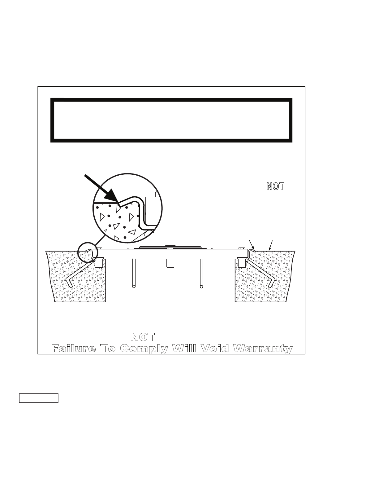
Owner: Your Installer Is Responsible For
The Concrete Floor Being Finished To
Grade Angle, NOT
To The Top Of The Lift.
Failure To Comply Will Void Warranty
Failure To Comply Will Void Warranty
Edge Of
Grade
Indicator
Concrete MUST BE Finished To
Edge Of Grade Indicator, NOT
The Top Of The Lift. Finished
Floor Level Must Be 1/4” Below
Top Of Lift On All Sides.
Concrete
Grade Indicator
IMPORTANT
Contact with the electrical heating coils could cause electrolysis and damage the lift and/or its
components. Make sure the lift frame concrete anchors do not contact electrical heating coils, or re-bar that may be
in contact with other embedded electrical sources. The lift being physically connected to any source which promotes
electrolysis will void the warranty.
2
Page 3
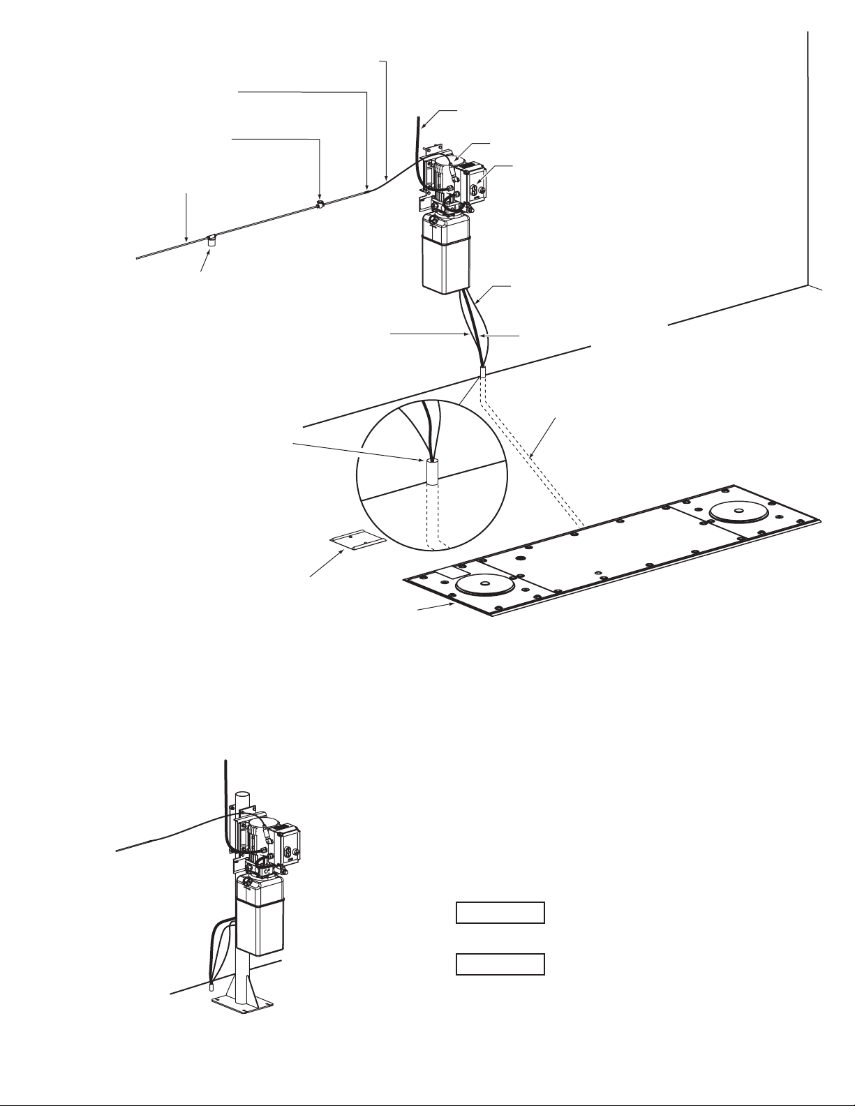
Power Unit
&
Master Control Panel
Mounted On Optional Pedestal
PVC Conduit for Air and Hydraulic
Hose (by Installing Contractor)
Hydraulic Hose to Lift
(by Installing Contractor)
Lift (by Rotary)
Wheel Spotting
Dish (by Rotary)
1/4" Air Line to Locking Latch
And LDS Sensor (by Rotary)
1/4" Air Line to
LDS Sensor (by Rotary)
Electrical Power Supply
(by Instaliing Contractor)
Power Unit (by Rotary)
Master Control Panel (by Rotary)
In-line Air Filter (by Rotary)
1/2" Air Line to Compressor or
Air Main (by Installing Contractor)
Shut Off Valve And Female Fitting
(by Installing Contractor)
In-Line Pressure Regulator/Water
Separator (by Installing Contractor)
1/4" Airline
To In-line Regulator (Inside Master Control Panel)
IMPORTANT!!!:
After Routing The
Air Lines & Hydraulic Hose
Do Not Cap Either End
Of Pipe Chase. Air
Must Vent Out
In Order For
LDS To Work Properly.
IMPORTANT
IMPORTANT
Please follow these instructions to ensure a good installation
and satisfactory operation of the lift. Check your shipment
against the product load list and shipping papers. Enter claims for
damage or shortage with the delivering carrier at once.
• Afterinstallation,pleasereturnthisbooklettotheliterature
package and give to lift owner/operator.
• Literaturepackageshouldbekeptattachedtopowerunitfor
easy access.
• Reviewentireinstallationinstructionsbeforebeginning
excavation.
The center cover is designed for foot traffic
only.
Restrict all unauthorized persons from going
near excavation. OSHA standard restricts anyone from getting in
excavated hole, unless OSHA guidelines are followed. See OSHA
Excavating Standard CFR 1926.
3
Page 4
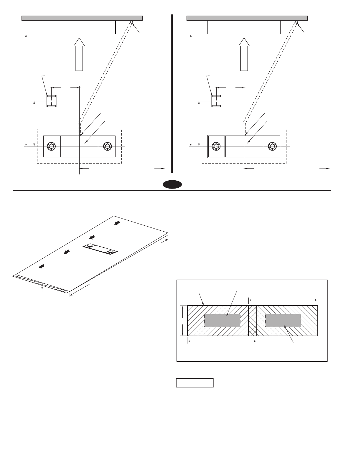
Wheel
Spotting Dish
2' 5"
APPROACH
PVC Conduit
Entrance for Air
& Hydraulic Hose
NOTE: Adjust Entrance
For Pedestal Mounting
Installation See Fig. 8a
4' 9" Swing Arm Lifts
5' 0" Moveable Pad Lifts
WORK BENCH (TYPICAL)
12'-0" Min. to
Nearest
Obstruction
or Per
Section 1c
5'-6" Min. to nearest obstruction
Foot traffic only on center cover
SL210i Series
Wheel
Spotting Dish
2' 5"
APPROACH
PVC Conduit
Entrance for Air
& Hydraulic Hose
NOTE: Adjust Entrance
For Pedestal Mounting
Installation See Fig. 8a
4' 9"
WORK BENCH (TYPICAL)
13'-0" Min. to
Nearest
Obstruction
or Per
Section 1c
5'-6" Min. to nearest obstruction
SL212i Series
PVC Inlet Into Containment Tube
Foot traffic only on center cover
PVC Inlet Into Containment Tube
1. Lift Location:
IMPORTANT
Recommended Floor Slope 0-1/16" Per Ft.
Drainage Direction
Drainage Directio
n
Drain
Continuous Trench
Lift Location
5'
Concrete Floor
10'
10'
Lift Location
A. Check architect’s layout if available. Lay out lift as shown in
Fig. 1. Recommended floor slope is 1/16" per foot.
Fig. 1
3. Concrete Preparation:
A. Run 2" PVC from Control Area to Containment Tube. PVC will
enter the Containment Tube 9-1/2" below finished floor grade.
Hole is centered horizontally in Containment Tube, Fig. 1.
B. Box out a 5' x 10' area around where lift is to be located.
NOTE: For multiple lift installations, boxed out areas will
overlap. Dig continuous trench, see illustration below.
C. Pour concrete floor ensuring not to get concrete in boxed out
area.
NOTE: By using this installation method, the RAI can more
accurately set lift to proper grade relative to finished floor.
Reference Page 2.
B. SL210i: The 5' 6" centerline to side and 12' 0" centerline
to front and rear dimensions should be maintained to provide
adequate working space. The minimum overhead clearance
should be 85" plus height of highest vehicle to be raised. 24' 0"
length bay recommended. Other lengths may be used, provided
ample clearance is maintained at each end of lift.
SL212i: The 5' 6" centerline to side and 13' 0" centerline to front
and rear dimensions should be maintained to provide adequate
working space. The minimum overhead clearance should be
88" plus height of highest vehicle to be raised. 26' 0" length bay
recommended. Other lengths may be used, provided ample
clearance is maintained at each end of lift.
C. Base Unit Lifts: If you are planning to install roll-on/
wheel alignment runways, locate lift per instructions from
superstructure manufacturer. Use superstructure manufacturer's
instructions for fore and aft, side to side, and ceiling clearances.
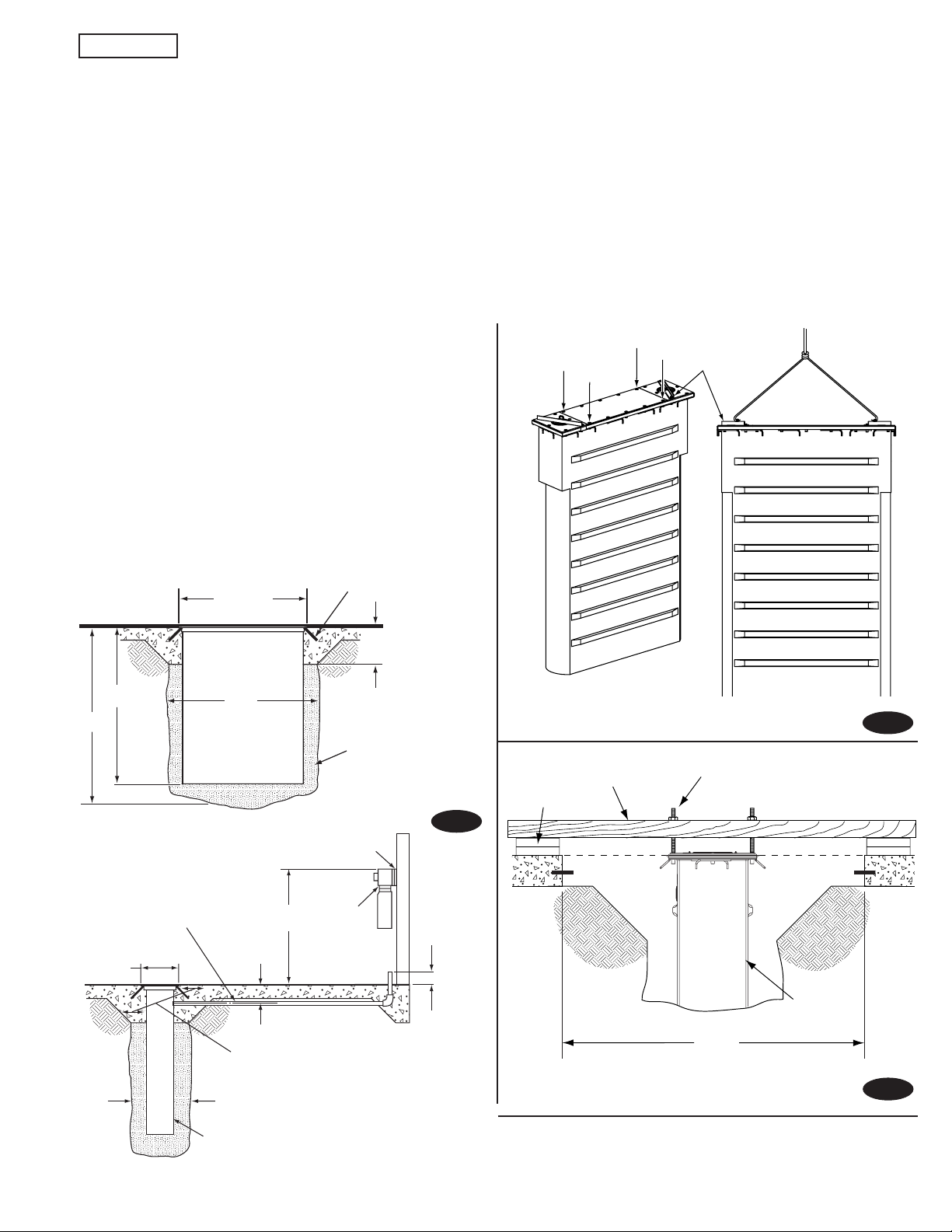
2. Excavation: Excavate hole to dimensions shown in Fig. 2.
Dig trench for 2" PVC pipe between lift and power unit location.
Trench should be dug 11" below finished floor grade. Air line and
hydraulic hose to be contained in this 2" PVC pipe.
4. Lift Setting:
Check the containment tube for holes due to
shipping damage. Do not install a damaged containment tube.
Contact Rotary Lift Customer Service.
A. Chain hoist must have capacity of 2,500 lbs. with a clear
swing of 9' 0". Rig sling for unit, attaching to the shipping strap,
Fig. 3, and lower assembly into hole. Center lift and be sure lift
containment inlet is located as shown in Fig. 1.
4
Page 5
Frame Anchor
105"
110"
18"
73-5/8"
Frame Width
96"
Clean Pea
Gravel Fill
36"
Lift & Containment Tube
7,200 lbs. maximum reaction
longitudinal and transverse
direction due to eccentric loads
15,000 lbs. maximum vertical loads
23-3/8"
Frame
2" PVC Pipe
9-1/2"
56"
Power
Unit
Wall Bracket
6"-8"
IMPORTANT
Owner: Your Installer Is Responsible For The
Lift and
Containment Tube
6 x 6's
Blocks
(2) 1/2"-13NC x 18" lg. Threaded Rod,
Flat Washers, & Nuts
60"
X
X
X
X
Shipping
Straps
Concrete Floor Being Finished To The Leading Edge Of The Grade
Angle (1/4" Below Top Of Lift), NOT To The Top Of The Lift, Fig. 5.
Failure To Comply Will Void Warranty.
B. Bend frame anchors out perpendicular to concrete frame and
downward approximately 45° to floor level, Fig. 2.
C. Remove and retain (4) 1/2"-13NC HHCS (marked with X, Fig.
3). Insert 1/2" Threaded Rods x 18" lg. into the holes and secure in
place using 1/2" flat washers and nuts, Fig. 4.
D. Attach 6 x 6’s to support unit on existing floor and secure in
place with 1/2" flat washers and nuts, Fig. 4. Remove shipping
straps and install guide barrel bolts in open holes and torque to 60
ft-lbs. Remove protective covers from top of jacks.
E. Plumb and level by placing machinist level on top of jack. Do
Not plumb or level off unit frame. See Fig 5.
F. Shore Lift Securely!
G. Connect 2" PVC to containment tube, chamfer PVC entering
containment tube seal and lubricate I.D. of seal with grease or
oil to ease entry of PVC into seal. PVC pipe should extend into
containment tube 1" maximum.
NOTE: If your PVC pipe and containment inlet do not align, you
may have to cut back PVC pipe, and attach 2" Flexible PVC to
make connection. All PVC joints MUST be leak proof.
H. Recheck plumb.
Fig. 3
Fig. 2
Fig. 4
5
Page 6
5. Backfill:
CAUTION
IMPORTANT
X
X
XX
X
X
X
X
X
X
Tape Covers
Over Plungers
Tape Covers
Over Plungers
Center Cover
Grade Indicator
Leading
Edge
Concrete
Floor
Machinist Level
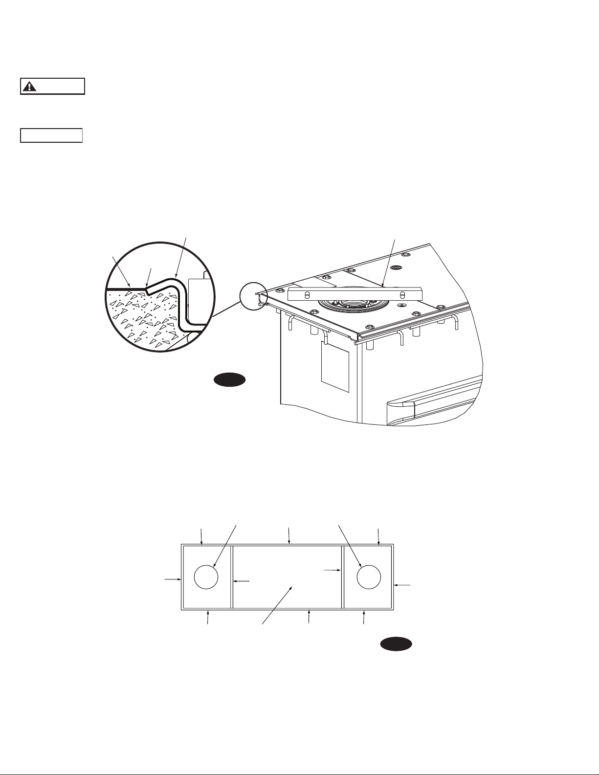
A. Duct tape joint areas indicated by X, Fig. 6, to protect these
areas during backfill and concrete work. Backfill around unit
using only pea gravel to within 18" of top of finished floor.
Do not use a mechanical tamper or saturate
the backfill material to achieve compaction. This could cause lift
containment sides to bend inward, HAND TAMP ONLY.
Do Not fill plunger with any ballast material.
B. Complete backfill and tamp pipe trench.
C. After lift is backfilled, make final elevation and plumb checks,
Fig 5.
D. Make sure frame anchors are bent out, Fig. 7.
Fig. 5
Fig. 6
6
Page 7
Lift and
Containment Tube
Bend Out
Frame Anchors
Rebar or Stud Anchor
Grade Indicator
Leading
Edge
Concrete
Floor
6. Concrete Work:
IMPORTANT
IMPORTANT
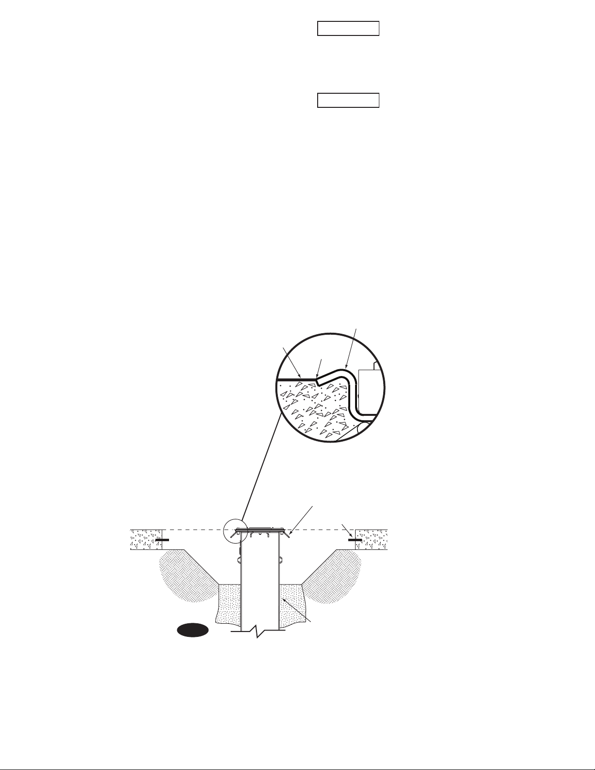
A. Leave 6 x 6's in place.
B. New concrete around the lift must be keyed into existing floor
with rebar or stud anchors, Fig. 7.
C. A minimum concrete strength of 3,000 PSI is suggested. DO
NOT use calcium chloride as a curing accelerator. If using a
curing accelerator, we recommend a non-chloride additive such
as High Early* or equivalent.
D. Pour concrete floor, being careful not to run concrete in and
around top surface of lift unit.
Owner: Your Installer Is Responsible For The
Concrete Floor Being Finished To The Leading Edge Of The Grade
Angle (1/4" Below Top Of Lift), NOT To The Top Of The Lift, Fig. 7.
Failure To Comply Will Void Warranty.
It is imperative that lift be set level
regardless of floor slope or other factors. Trowel smooth and
allow to harden.
E. After concrete is set-up, remove 6 x 6's and threaded rods.
F. Reinstall the guide barrel bolts, use Loctite 242 (blue) on bolts
and torque to 60 ft.-lbs.
G. Do not use lift until concrete has achieved 3,000 PSI.
Fig. 7
7
Page 8
7. Power Unit:
Push nuts hold
bolts to brackets
Lowering
Valve
Fill
Breather
Cap
Power Unit
Bracket
(By Rotary)
Use (4)5/16"-18NC
x 1-1/2" lg. HHCS
Use (4)5/16"-18NC
Nuts and 5/16" Star
Washers
When Required
For Installing
Tr ansformer Box
(Can Be Mounted Left Or Right Side)
*For workbench installations mount transfomer box
behind power unit and on the inside side wall at least
18'' above the floor. Use supplied #10 x 3/8'' tapping
screws. Drill 0.136'' pilot holes.
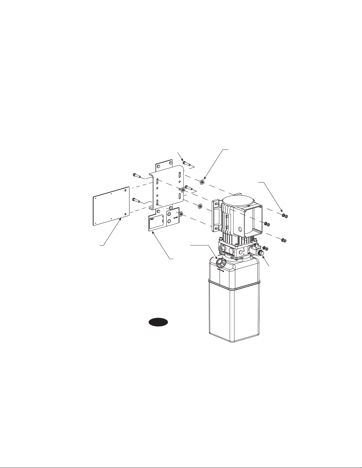
A. Wall Mounting: For operating convenience, locate Power Unit
bracket so top of bracket will be approximately 56" above floor,
Fig. 2.
B. Locate and mount the power unit bracket, using (4) 3/8" wall
anchors, on the wall, Fig. 8. Anchors must be able to hold 20 lbs.
of shear force.
C. Put (4) 5/16"-18NC x 1-1/2" HHCS through wall bracket using
push-nuts to hold in place, Fig. 8.
D. Mount power unit, with motor up, to the power unit bracket
and install (4) 5/16" nuts and lock washers, Fig.8.
8. Hose And Elbow Attachment (Hose Provided By Installer):
A. Hose must meet Dayco EZ Flex 150 or equivalent specs. with
3,000 PSI minimum working pressure, 3/8" I.D. with 9/16-18THD,
JIC fitting, female swivel ends.
B. Hose must be free of debris. Inspect all threads for damage.
C. Install hose onto elbow adapter on power unit, Fig. 9.
D. Do not route hose to lift at this time.
Fig. 8
8
Page 9
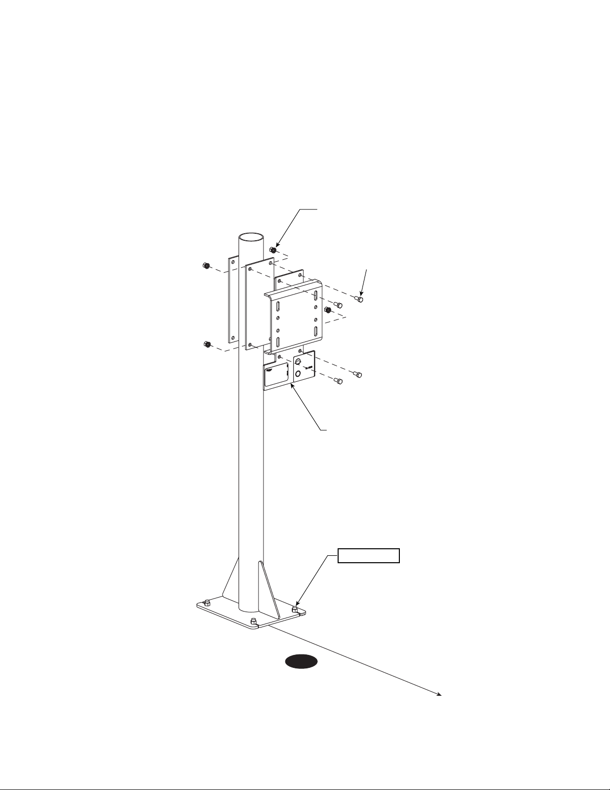
E. Pedestal Mounting: Pedestal must be anchored to the floor
Secure Pedestal
To Floor With 3/8”
Anchor Bolts Before
Attaching Power Unit
Use (4)5/16"-18NC
x 3/4" lg. HHCS
Use (4)5/16"-18NC
Nuts and 5/16" Star
Washers
IMPORTANT
30" From Nearest Obstacle
Power Unit
Bracket
(By Rotary)
with 3/8" anchor bolts before attaching power unit, Fig. 8a.
F. Use base for pattern to mark holes for anchoring. Pedestal
must be anchored at least 30" away from the any obstacle to
allow for wiring and maintenance of the power unit, Fig 8a.
G. Mount power unit bracket to pedestal with (4) 5/16"-18NC x
1-1/2" HHCS, (4) 5/16" nuts and lock washers, Fig. 8a.
H. Put (4) 5/16"-18NC x 1-1/2" HHCS through power unit bracket
using push-nuts to hold in place, Fig. 8b.
I. Mount power unit, with motor up, to the power unit bracket
and install (4) 5/16" nuts and lock washers, Fig.8b.
Fig. 8a
9
Page 10
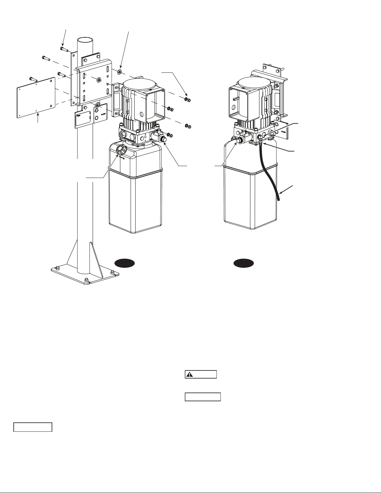
ATTENTION
CAUTION
IMPORTANT
Use (4)5/16"-18NC
x 1-1/2" lg. HHCS
Use (4)5/16"-18NC
Nuts and 5/16" Star
Washers
Lowering
Valve
Push Nuts Hold
Bolts To Bracket
Fill
Breather
Cap
Crimped Hose
Sleeve (Typical)
Elbow Adapter
Power Unit Hose
to Lift. Hose must
meet Dayco EZ
Flex 150 or equiv.
Specs. with 3,000
PSI min. working
pressure, 3/8" I.D.
with 9/16-18THD
JIC Fitting, Female
Swivel Ends.
When Required
For Installing
Tr ansformer Box
(Can Be Mounted
Left Or Right Side)
Fig. 8b
9. Mounting Master Control Panel, Fig. 10:
A. Remove front cover of Master Control by unscrewing the (4)
screws and unplugging the harness.
B. Remove covering over the front of the capacitor box on the
motor of the power unit and find gasket.
C. Place gasket on the front of the capacitor box, Figs. 10, 10a.
D. Route (2) motor wires through gasket and the hole in the back
of Master Control Box. Fasten to indicated locations on terminal
block, Figs. 10, 10a.
E. Route green ground wire through gasket and fasten to the
ground screw inside the capacitor box of the motor, Figs. 10, 10a.
F. Have a certified electrician run appropriate power supply to
the side of the capacitor box of the motor and run the ground wire
and power wires through the gasket and the hole in the back of
the master control box. Fasten the ground wire to the additional
ground screw in back plate and fasten the (2) power wires to the
indicated locations on the terminal block.
Fasten spade terminals to the ends of the wires
sized for fastening to a #8 screw for 1 phase and #A6 screw for 3
phase, Fig. 10, 10a.
Fig. 9
G. Fasten the Master Control Box with the (4) M5x10 PHMS
included making sure the gasket seats between the capacitor box
sides and the back of the Master Control Box, Figs. 10, 10a.
H. Push excess ground and power wires into the capacitor box
behind the control, Figs. 10, 10a.
I. Orient bulkhead for input air to desired position and tighten
securely, Figs. 10, 10a.
J. Plug harness and reattach cover of the master control box,
making sure all wires are inside the box and plug is above the
terminal block, Figs.10, 10a.
208V. Motor damage may occur.
Never operate the motor on line voltage less than
Use separate circuit for each power supply.
Protect each circuit with time delay fuse or circuit breaker. For
single phase 208-230V, use 20 amp fuse, and three phase use 20
amp fuse. For three phase 460V, use 10 amp fuse. All wiring must
comply with NEC and all local electrical codes.
Note: Standard single phase motor CAN NOT be run on 50Hz. line
without a physical change in the motor.
Wire motor according to wiring diagram provided.
10
Page 11
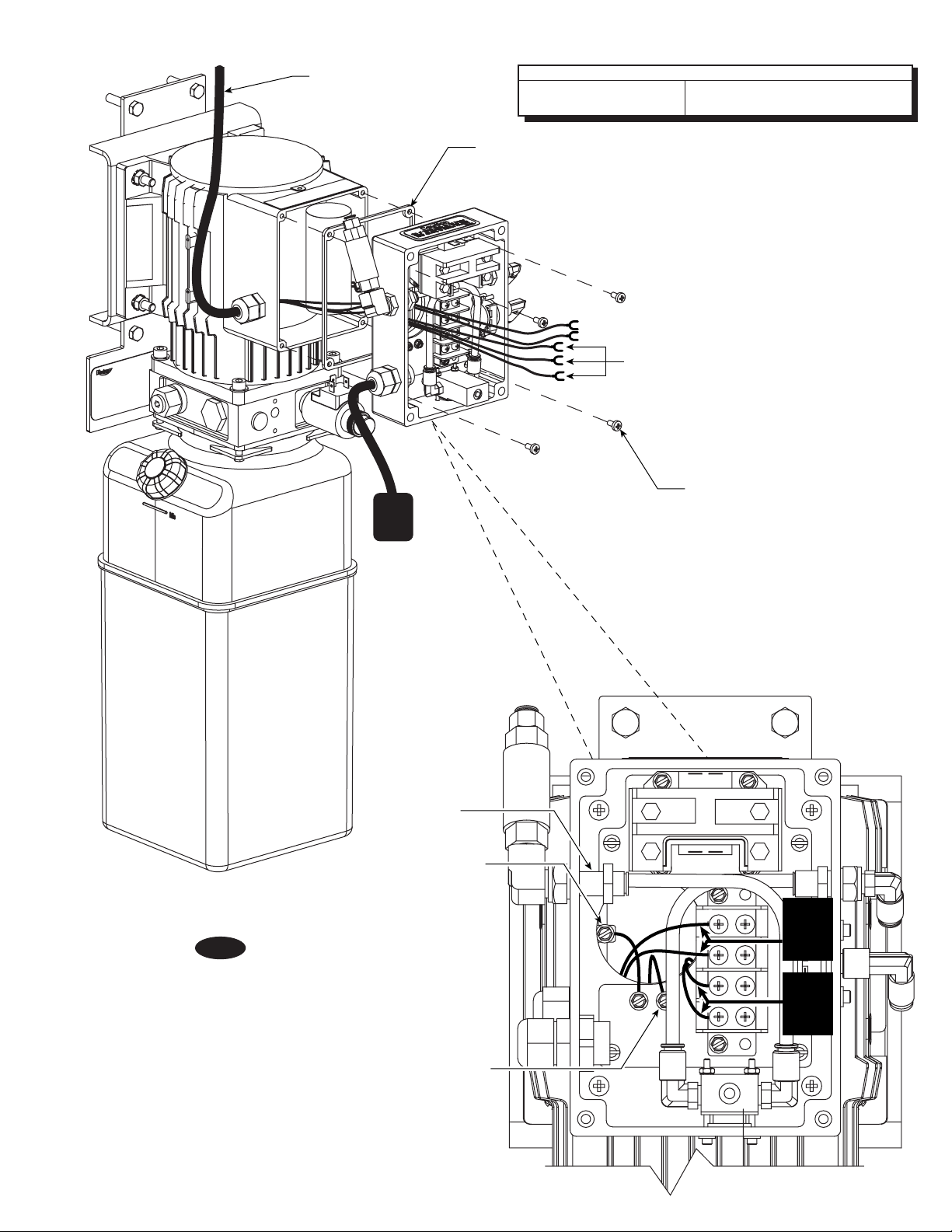
Power Cable
And Strain Relief
(Provided By Installer)
Gasket
M5 x 10
Mounting Screws
Spade Te rminals
For #8 Screws
(By Installer)
Green Screw
And Ground Wire
In Motor
Capacitor Box
Orient To Desired
Position And Tighten
Securely
Green Screw
And Ground Wire
For
Power Supply
Motor
Wires
Power
Supply
Wires
Single Phase Rotary Power Unit
MOTOR OPERATING DATA - SINGLE PHASE
LINE VOLTAGE
208 - 230 Volts 60 HZ
NOTES:
1. Unit not suitable for use in unusual conditions.
Contact Rotary for moisture and dust environment
duty unit.
2. Verify Coil Rating Matches Supply Voltage
3. Motor rotation is counter clockwise when viewed
from top of motor.
RUNNING MOTOR VOLTAGE RANGE
197 - 253 Volts
Fig. 10
11
Page 12
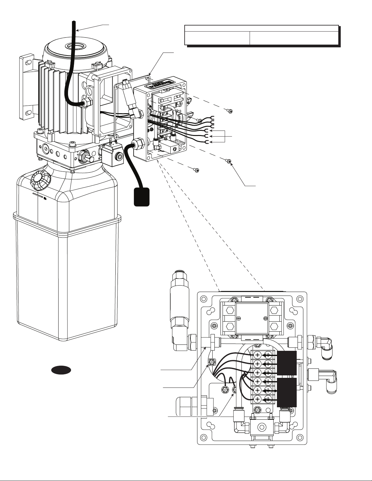
Power Cable
And Strain Relief
(Provided By Installer)
Gasket
M5 x 10
Mounting Screws
Spade Terminals
For #6 Screws
(By Installer)
Power
Supply
Wires
Motor
Wires
Green Screw
And Ground Wire
In Motor
Motor Box
Orient To Desired
Position And Tighten
Securely
Green Screw
And Ground Wire
For
Power Supply
Three Phase Rotary Power Unit
MOTOR OPERATING DATA - THREE PHASE
LINE VOLTAGE
208 - 230 Volts 60 HZ
NOTES:
1. Unit not suitable for use in unusual conditions.
Contact Rotary for moisture and dust environment
duty unit.
2. Verify Coil Rating Matches Supply Voltage
3. Motor rotation is counter clockwise when viewed
from top of motor.
RUNNING MOTOR VOLTAGE RANGE
197 - 253 Volts
Fig. 10a
12
Page 13
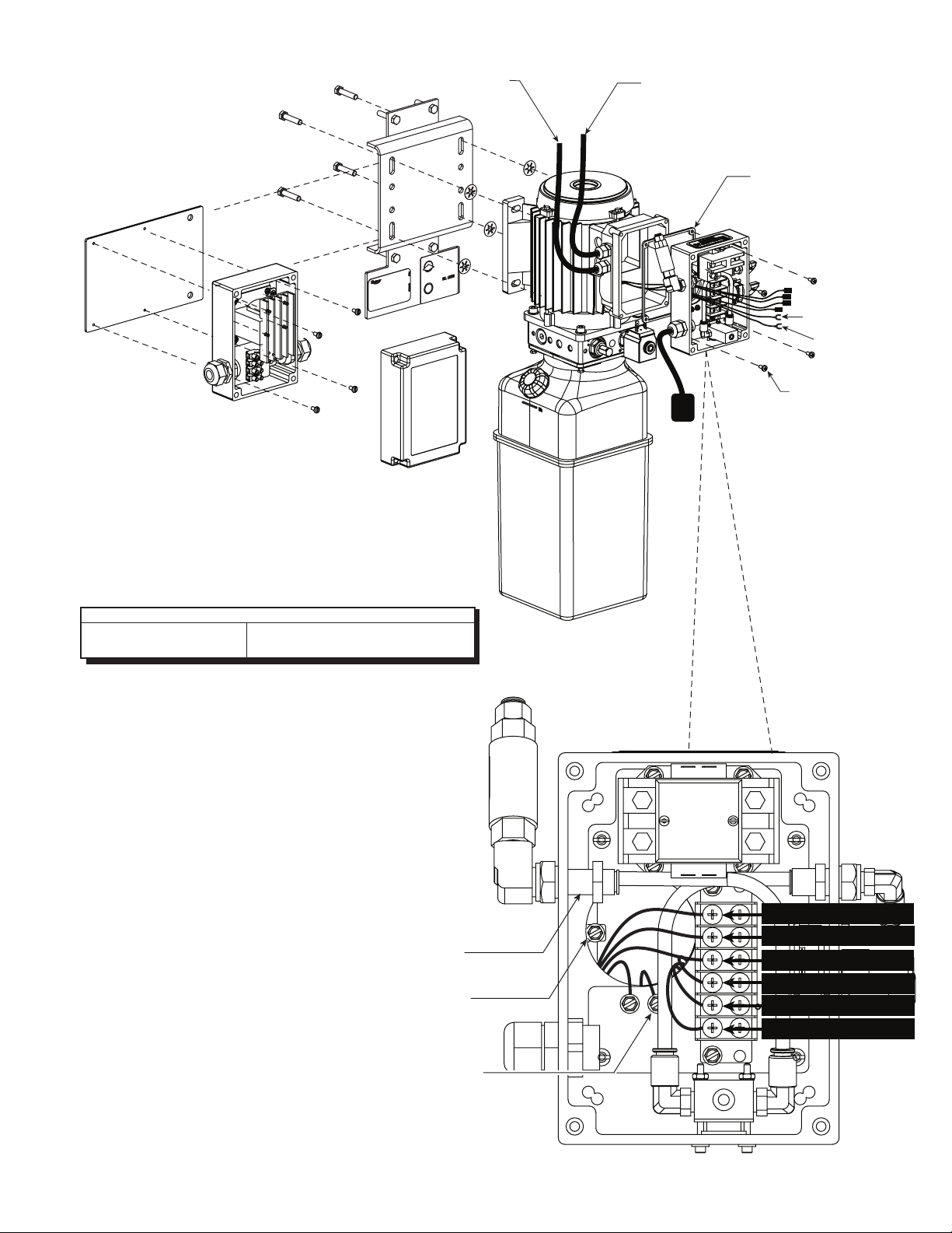
Power Cable From Tr ansformer
And Strain Relief
(Provided By Installer)
Controls Cable From Transformer
And Strain Relief
(Provided By Installer)
Gasket
M5 x 10
Mounting Screws
To Motor
To Motor Ground
Green Screw
And Ground Wire
In Motor
Motor Box
Orient To Desired
Position And Tighten
Securely
Green Screw
And Ground Wire
For
Power Supply
Power Supply Wire
Power Supply Wire
Control Supply Wire
Control Supply Wire
Motor Wires
Motor Wires
Transformer
For 480V
Bracket
For
Transformer
Three Phase Rotary Power Unit
MOTOR OPERATING DATA - THREE PHASE HIGH VOLTAGE
LINE VOLTAGE
460 Volts 60 HZ
NOTES:
1. Unit not suitable for use in unusual conditions.
Contact Rotary for moisture and dust environment
duty unit.
2. Verify Coil Rating Matches Supply Voltage
3. Motor rotation is counter clockwise when viewed
from top of motor.
RUNNING MOTOR VOLTAGE RANGE
414 - 506 Volts
13
Page 14
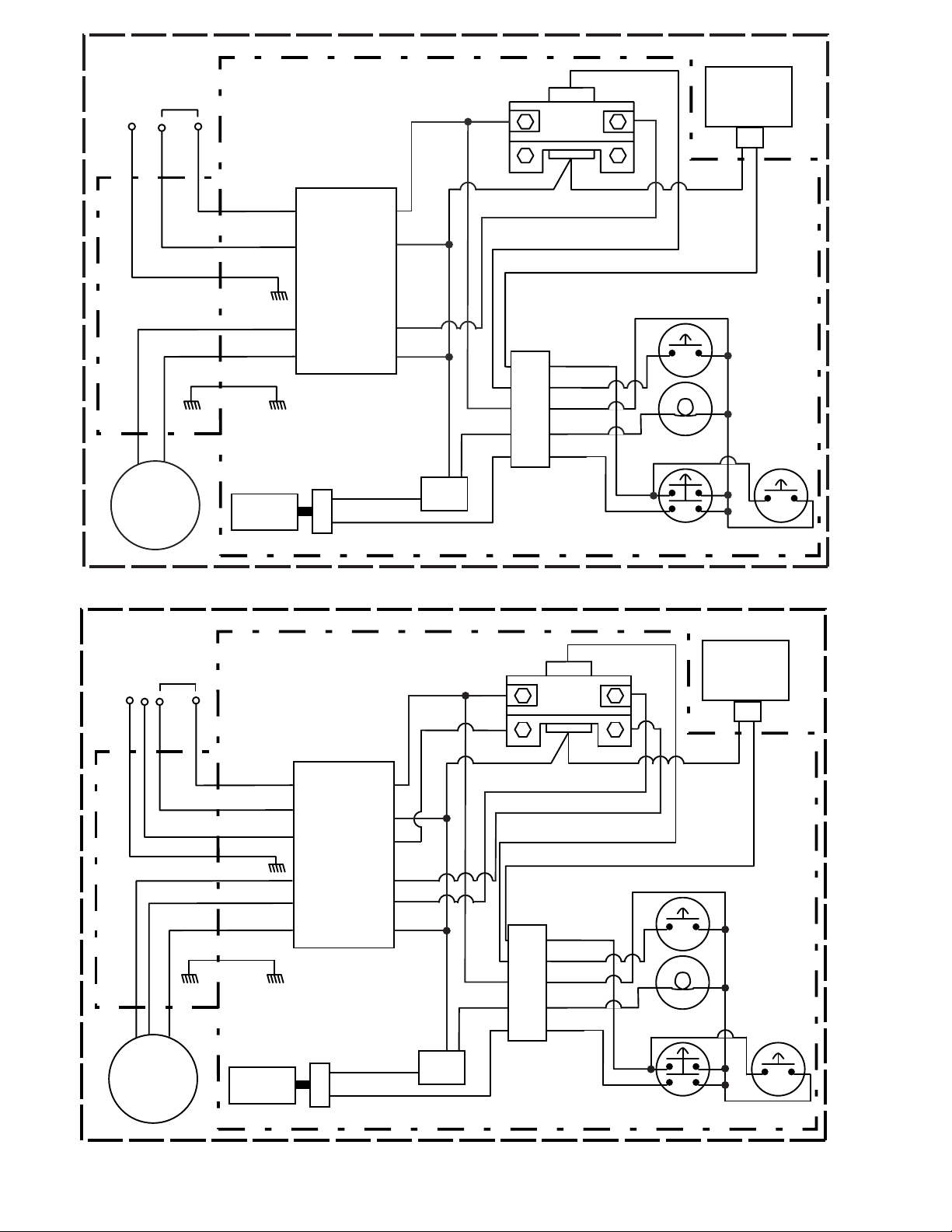
U
D
White
White
Orange
White
DIN
Red
Red
Red
Red
Red
White
Black
Red or
White
Blue
Orange
Orange
Orange
Black
Orange
Lowering
Valve
Blue
LL
Latch1
Black
Black
Black
Coil
Connector
LDS
Connector
Red
LDS*
LDS*=Liquid Detection System
Terminal Block
Green
Single Phase
208-230V
SmartLift® System Diagram
Label Part # NP839 Rev. -
L1 T1
L2 T2
MV1 TMV1
MV2 TMV2
Green
Motor
Motor Enclosure
Control Enclosure
U
D
White
White
Orange
White
DIN
Red
Red
Red
Red
Red
White
Black
Red or
White
Blue
Orange
Orange
Orange
Black
Orange
Lowering
Valve
Blue
LL
Latch1
Black
Black
Black
Black
Coil
Connector
LDS
Connector
Red
LDS*
LDS*=Liquid Detection System
Terminal Block
Green
Three Phase
208-230V
SmartLift® System Diagram
Label Part # NP926 Rev. -
L1 T1
L2 T2
L3 T3
MV2 TMV2
MV1 TMV1
MV3 TMV3
Green
Motor
Motor Enclosure
Control Enclosure
Black
Black
Black
14
Page 15
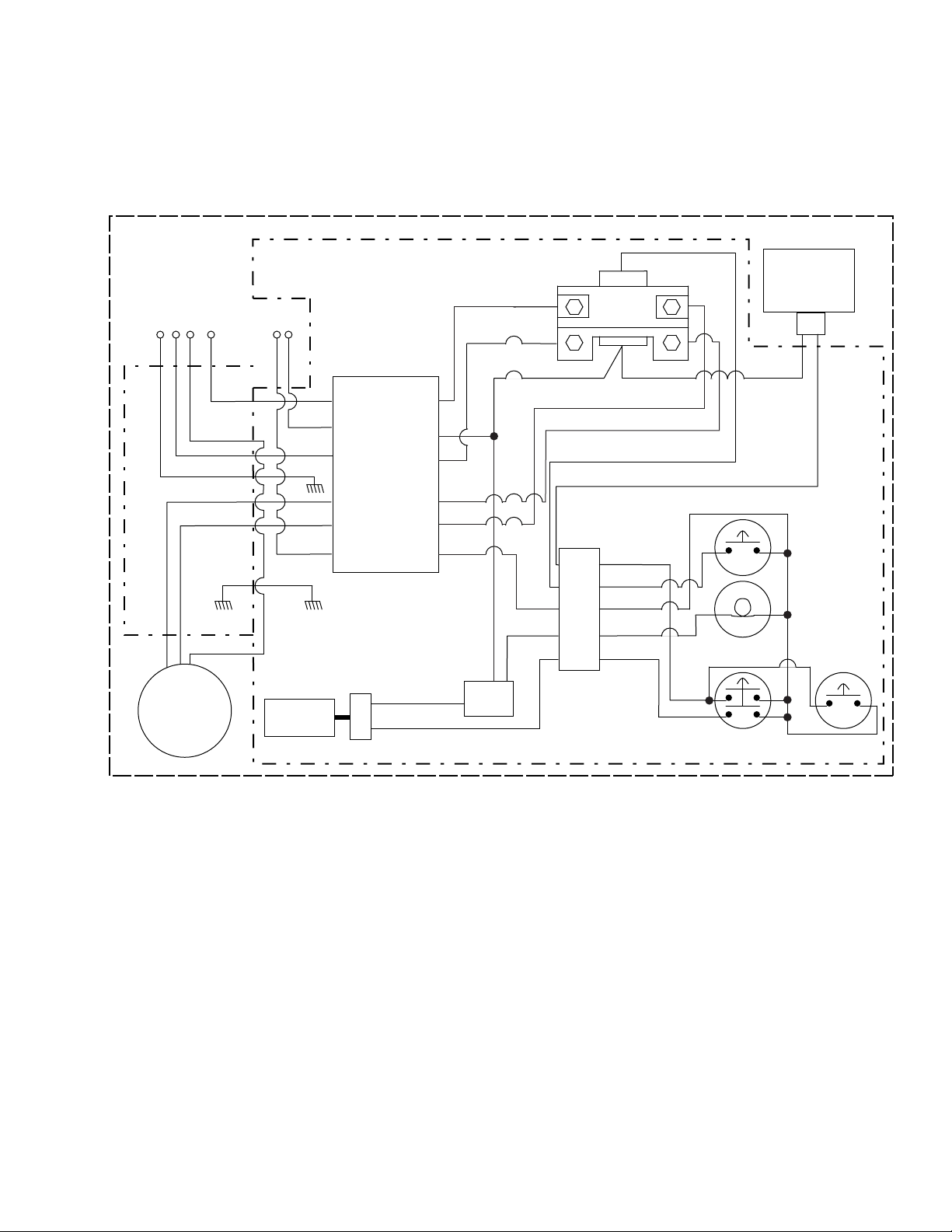
U
D
White
White
Orange
White
DIN
Red
Red
Red
Red
Red
Red
Black
Red or
White
Blue
Orange
Orange
Orange
Black
Orange
Lowering
Valve
Blue
LL
Latch1
Black
Black
Black
Black
Coil
Connector
LDS
Connector
Red
LDS*
LDS*=Liquid Detection System
Terminal Block
Green
Three Phase
480V
220V
SmartLift® System Diagram
Label Part # NP947 Rev -
L1 T1
X1 CV1
L2
L3
T2
MV2 TMV2
MV1 TMV1
X2 CV2
Green
Motor
Motor Enclosure
Control Enclosure
Black
Black
Black
Black
Black
Black
15
Page 16
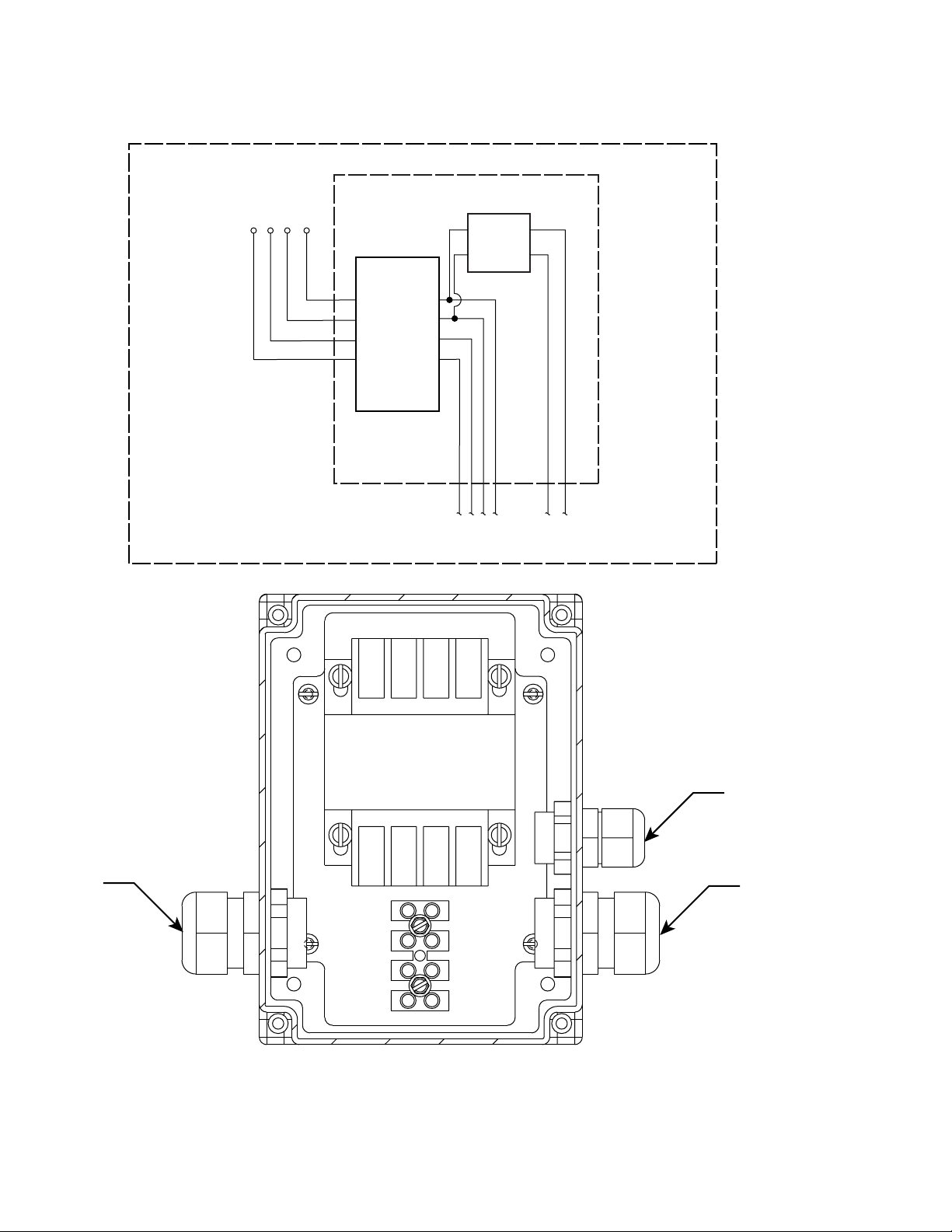
NP952 Rev -
Terminal Block
TransformerIncoming
480V
L1
L2
L3
PE
L1L2L3PE
To Control Box
(480V)
To Control Box
(220V)
L1
L2
L3
PE
X1
X2
H1
H2
Power In
Control Voltage Out
Motor Voltage Out
16
Page 17
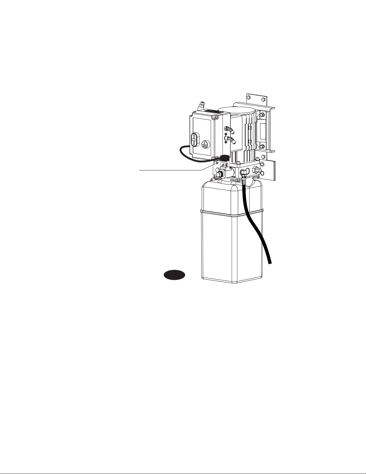
Lowering Valve Cord
From Master Control Panel
Plugs Into Lowering Valve
Tighten Screw On
To p Of Plug After
Plugging In
10. Lowering Valve:
Plug Lowering Valve cord from master control panel into lowering
valve on power unit, Fig. 11.
12. Adapter Extension Racks (For SL212i only), Fig. 15:
Fig. 11
17
Page 18
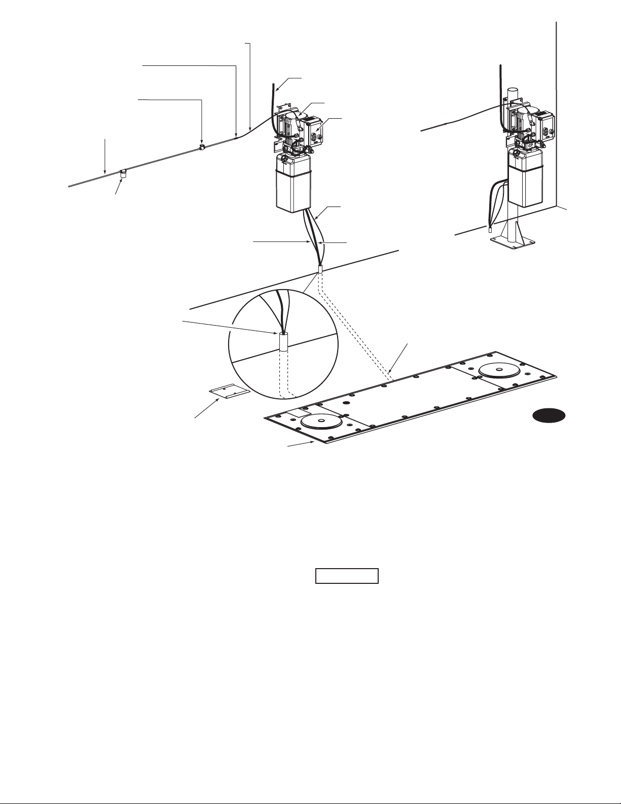
PVC Conduit for Air and Hydraulic
Hose (by Installing Contractor)
Hydraulic Hose to Lift
(by Installing Contractor)
Lift (by Rotary)
Wheel Spotting
Dish (by Rotary)
1/4" Air Line to Locking Latch
And LDS Sensor (by Rotary)
1/4" Air Line to
LDS Sensor (by Rotary)
Electrical Power Supply
(by Instaliing Contractor)
Power Unit (by Rotary)
Master Control Panel
(by Rotary)
In-line Air Filter (by Rotary)
1/2" Air Line to Compressor or
Air Main (by Installing Contractor)
Shut Off Valve And Female Fitting
(by Installing Contractor)
In-Line Pressure Regulator/Water
Separator (by Installing Contractor)
1/4" Airline
To In-line Regulator (Inside Master Control Panel)
IMPORTANT!!!:
After Routing The
Air Lines & Hydraulic Hose
Do Not Cap Either End
Of Pipe Chase. Air
Must Vent Out
In Order For
LDS To Work Properly.
Power Unit
&
Master Control Panel
Mounted On Optional Pedestal
IMPORTANT
*LDS = Liquid Detection System
11. Supply Lines (By Installer): Remove duct tape and center
cover. Set Bolts and seal aside, taking care not to damage seal.
A. Hose:
1. Push the hose through the 2" PVC pipe chase from power
unit to lift unit, Fig 12 & Fig. 14.
2. Install to hydraulic fitting in lift containment inlet.
B. LDS Assembly:
1. Remove sensing tube from inside of lift containment.
2. Install sensing tube into LDS valve assembly as shown,
Fig. 12a. Sealant may be required on threads to ensure air
tight connection. Connection must be air tight to 90 PSI.
Hand tighten tube then turn an additonal 2 turns; maximum
engagement is 3/8".
3. Install LDS system onto the channel that the sensing tube
was shipped in, making sure to place sensing tube inside wire
ties, Fig. 12b.
B. Air Lines:
to 120 psi.
1. Install in-line air filter and female 1/4" pipe to 1/4" tube
fitting, Fig. 12.
2. Cut to fit 1/4” air line and attach it to the in-line air filter and
inline regulator on master control panel, Fig. 13.
3. Attach 1/4" polypropylene tubing into (2) elbows on the side
of the Master Control Panel, Fig 13.
Shop air supply pressure must be between 90
Fig. 12
18
Page 19
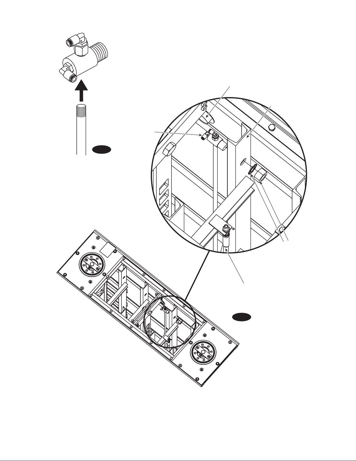
PVC Conduit
Nut And
Washer
LDS
Valve
Assembly
Vertical
Hose
Sensing Tube
Shipped Inside
This Channel
Fig. 12a
Fig. 12b
19
Page 20
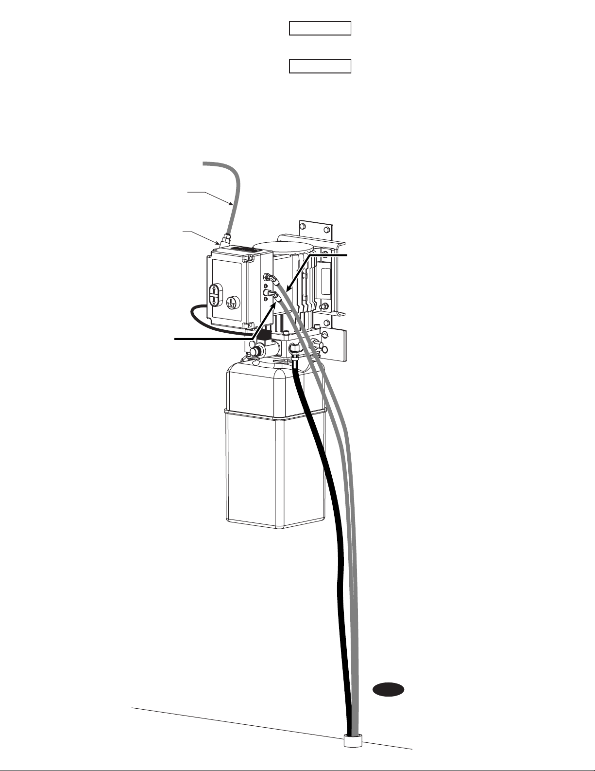
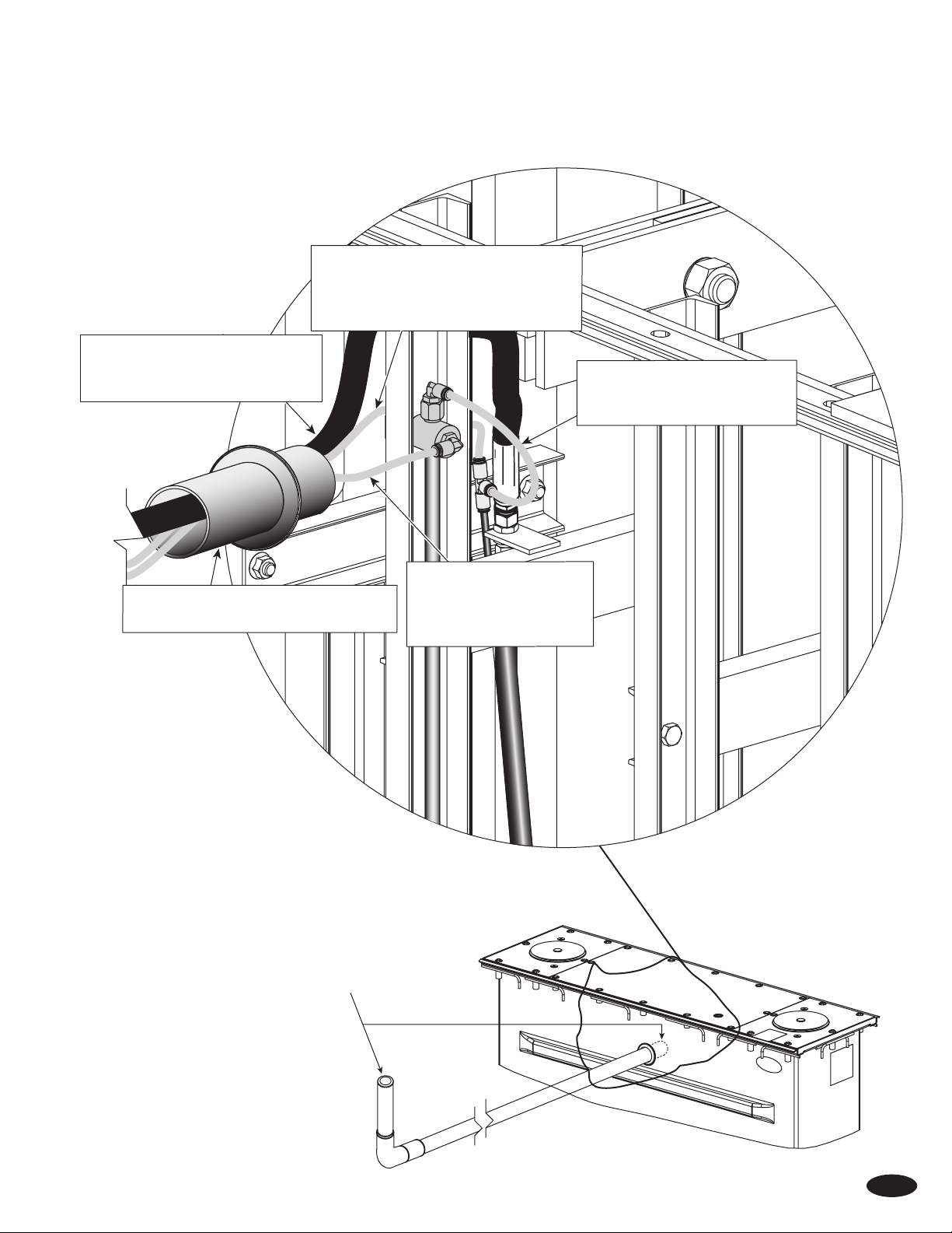
4. Push the tubing through the 2” PVC pipe chase to the LDS*
1/4” Air Line
To In-Line Air Filter
In-Line Regulator
1/4” Air Line To Air Tee In
Containment Tube Attached
To Air Line On Vertical Hose
1/4” Air Line To LDS
Valve Assembly In
Containment Tube
IMPORTANT
IMPORTANT
valve assembly, Fig. 14.
5. Cut to fit 1/4” air line and run it from air line attached to
vertical hose using the union tee to the top elbow of the LDS*
assembly, Fig.14, inside the lift.
NOTE: All 1/4” polypropylene air line must have a 300 PSI
working pressure.
Failure to connect air lines properly will cause a
fault error on the master control panel.
After routing the air lines and hydraulic hose DO
NOT cap either end of the PVC conduit. Air must vent out in order
for the LDS* to work properly, Figs. 14.
Fig. 13
20
Page 21
CONTAINMENT
NOT SHOWN
FOR CLARITY
OF VIEW
(#2) 1/4" Airline From Air Valve
In Master Control Panel
(Upper Elbow)
Plugs Into Union Te e
PVC Conduit
Back To Master Control Panel
1/4" Airline From
Pressure Switch In
Master Control Panel
(Lower Elbow)
Hydraulic Hose
Attaches To Hydraulic Fitting
In Lift Containment Inlet
Cut To Fit 1/4" Airline From
Union Tee to
LDS Valve Assembly
LDS
IMPORTANT!!!:
After Routing The
Air Lines & Hydraulic Hose
Do Not Cap Either End
Of PVC Conduit. Air
Must Vent Out
In Order For
LDS To Work Properly.
21
Fig. 14
Page 22
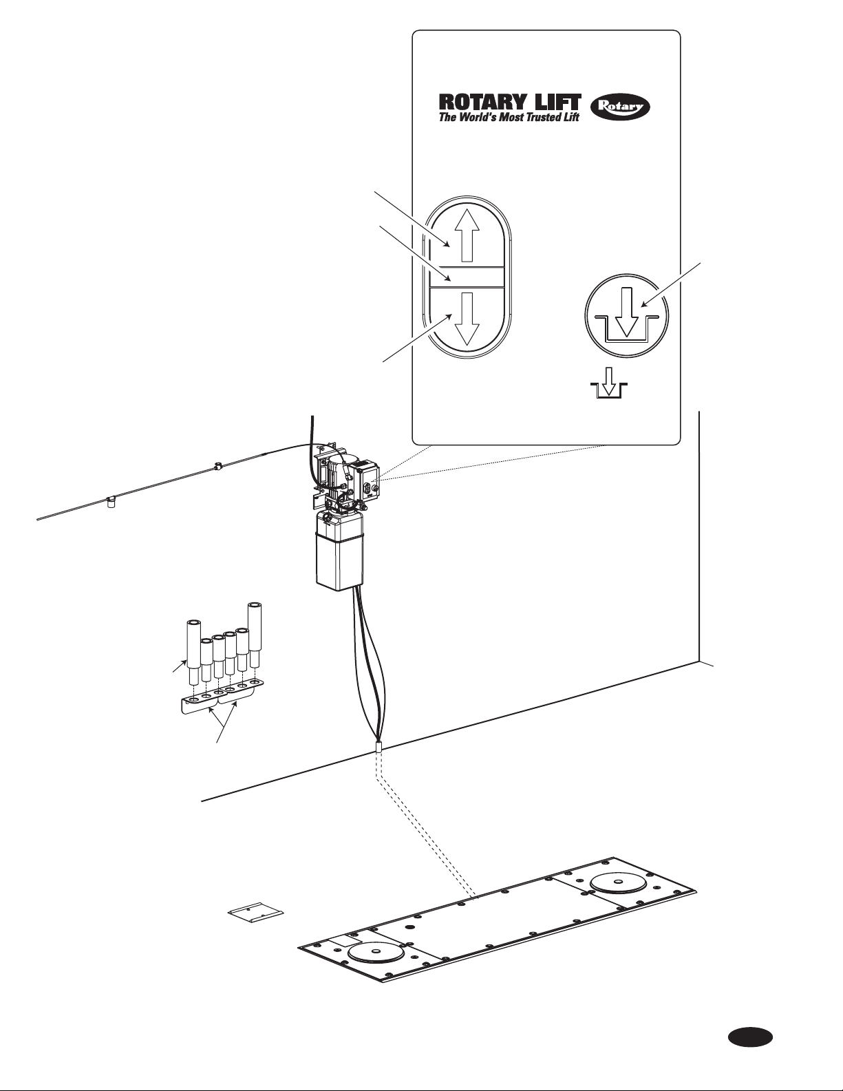
Adapter Extension Racks
Insert 4" and 8"
Extensions Into Racks
™
®
Liquid In
Containment
When Lit
Lower
To Lock
LOWER TO
LOCKS
LOWER
RAISE
LDS LIGHT
Fig. 15
22
Page 23
A. Locate and mount adapter extension racks on the wall
IMPOR TAN T
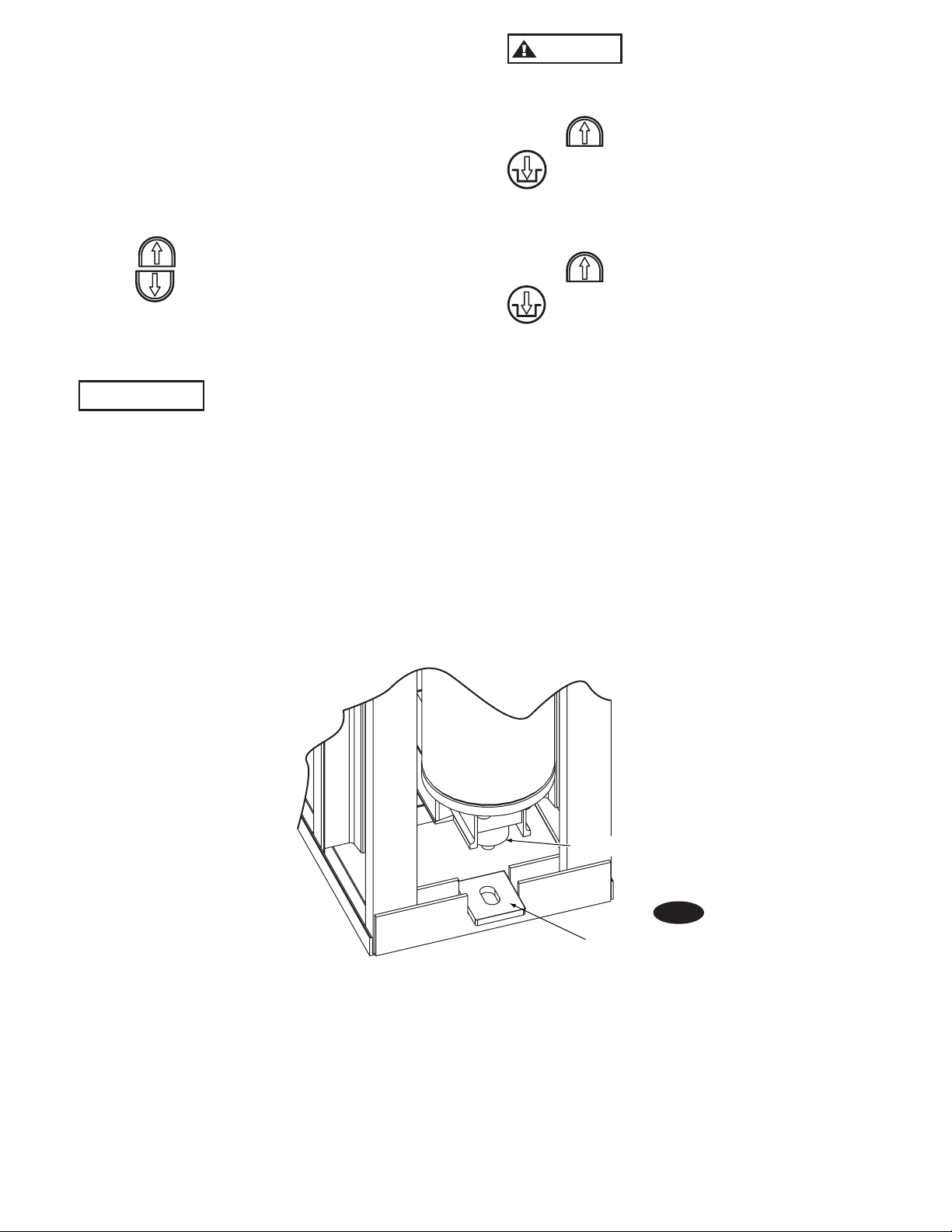
Cylinder Rod Boss
Load Pad
CAUTIO N
convenient to the bay area using (4) 3/8" wall anchors. Anchors
must be able to hold 20 lbs. of shear force.
B. Place 4" and 8" extensions into racks.
13. Fluid Filling:
A. System capacity is 19 quarts. Use Dexron III ATF, or Hydraulic
Fluid that meets ISO 32 specifications.
B. Remove fill-breather cap, Fig. 8.
C. Add fluid to power unit until it reaches the MIN_____ mark
on the tank.
D. Press RAISE button and raise lift to full rise, Fig. 15.
E. Press LOWER button to fully lower lift, Fig. 15.
F. Bleed lift by cycling to full rise several times.
G. Top off fluid to power unit until it reaches the MIN_____ mark
on the tank.
All lifts must be fully lowered before
changing or adding fluid.
If fill-breather cap is lost or broken, order a
replacement. DO NOT substitute with a solid plug.
14. Locking Latch Test; refer to Fig. 15:
A. Press RAISE button and raise lift in up position, press
LOWER TO LOCKS button and lower lift onto locks.
B. Make sure latch engages and releases.
15. Cylinder/Load Pad Test; refer to Fig. 15:
A. Press RAISE button and raise lift to full rise and press
LOWER TO LOCKS button to lower onto locks.
B. Look into the containment tube to check that the high pressure
cylinder rod is in the load pad hole, Fig. 16.
C. If not, use a nonmetal object (do not scratch or scar the
cylinder rods), try to move the cylinder rod. If it does not move
skip step D.
Fig. 16
23
Page 24
X
X
XX
X
X
X
X
X
X
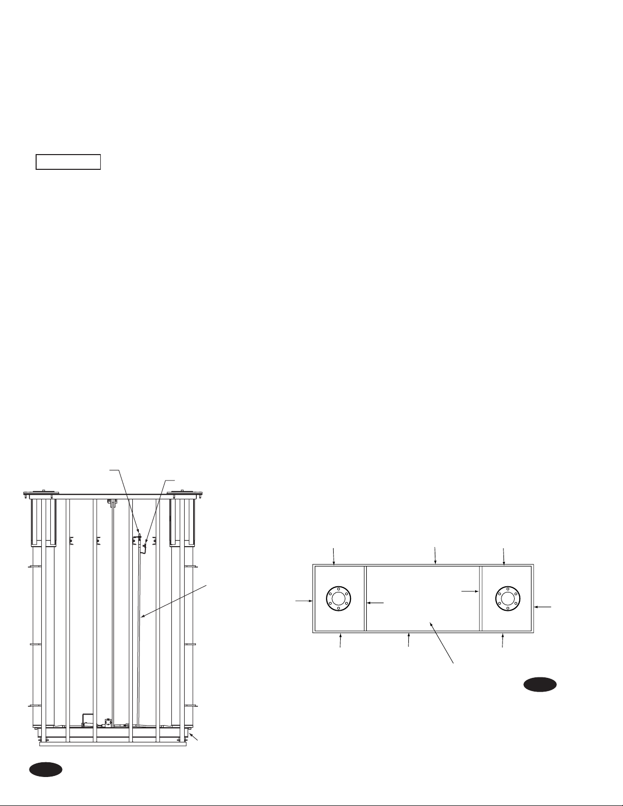
Center Cover
Equalizer
Beam
Bulkhead Fitting
Hydraulic
Hose
Air Hose Fitting
16. Hose Tracking Test:
IMPORTANT
Have someone raise the lift while another watches the tracking
of the hose between the bulkhead fitting and equalizer beam,
Figs. 17. If the hose does not track between the members of
the equalizer beam without rubbing, adjust bulkhead fitting as
necessary.
17. Setting Cover; refer to Fig. 21:
A. Insert cover seal into lip in opening, making sure all holes
align.
B. Install center cover onto seal.
C. Install and tighten cover retaining bolts. Torque to 60 ft-lbs.
Clean areas indicated with X, Fig. 18, and
seal with a premium 25 year silicone.
18. Superstructure:
Sl210i Series:
A. Base Unit Lifts: Install roll-on/wheel alignment runway per
instructions from superstructure manufacturer.
B. Swing Arm Superstructures:
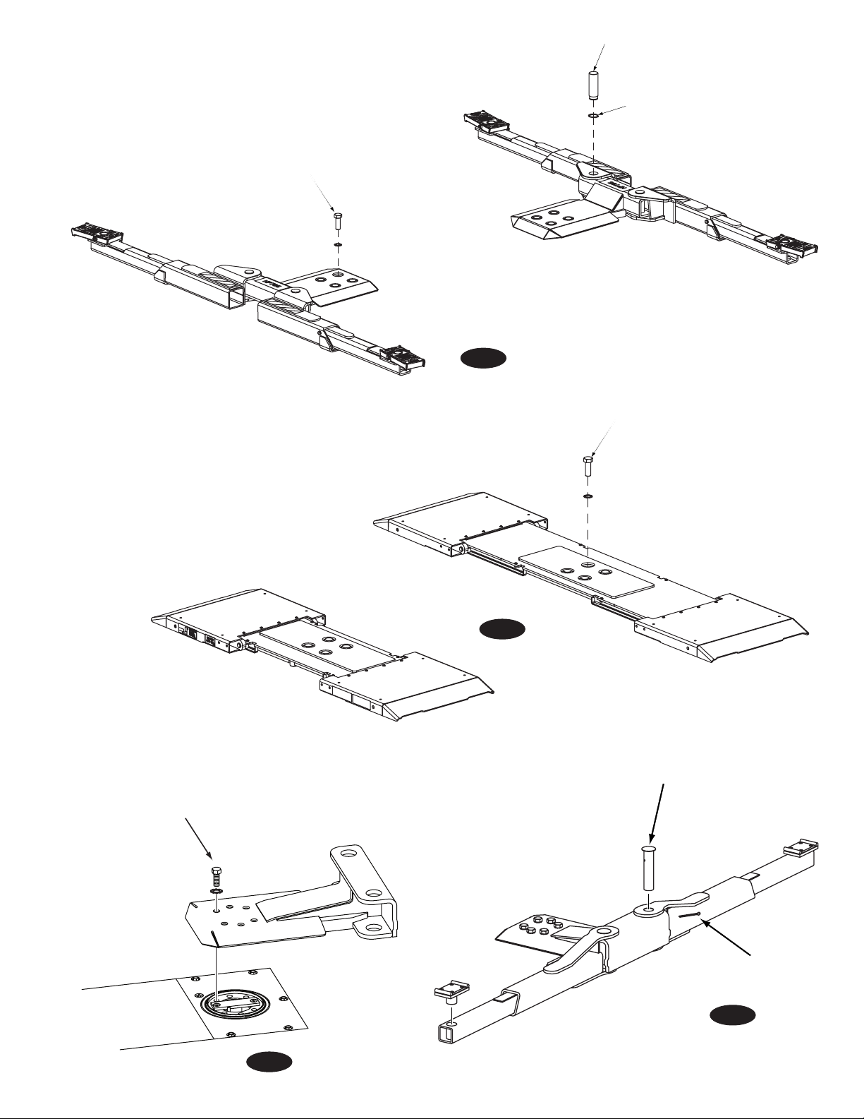
1. Install yokes to plungers with 7/8"-9NC x 2-1/2" HHCS and
7/8" external tooth lockwasher. Torque to 150 ft-lbs, Fig. 19.
2. Grease swivel arm pins and arm holes with Lithium grease.
3. Install (4) arm assemblies using the arm pins and snap
rings.
C. Moveable Pad Assemblies:
1. Install pads on lift using 7/8”-9NC x2-1/2” HHCS and 7/8”
external tooth lockwasher and torque to 150 ft.-lbs, Fig. 20.
SL212i series:
A. Base Unit Lifts: Install roll-on/wheel alignment runway per
instructions from superstructure manufacturer.
B. Swing Arm Superstructures:
1. Install yokes to plungers with 7/8"-9NC x 3-1/2" HHCS and
7/8" external tooth lockwasher. Torque to 150 ft-lbs., Fig. 21.
2. Grease swivel arm pins and arm holes with Lithium grease.
3. Install (4) arm assemblies using the arm pins and cotter
pins, Fig. 22.
19. Final Touches:
A. Lag wheel spotting dish to floor using two 3/8” anchors
provided. Verify model number of lift being installed and refer
to Fig. 1 for respective dimensions.
B. Raise lift and clean sand and dirt from plunger and lift area.
C. Mount multiple power source label on or next to the power
unit.
D. Double check to make sure the guide barrel and center cover
are sealed per Step 17.
Fig. 17
Fig. 18
24
Page 25
Arm Pin
Snap Ring
7/8"-9NC x 2-1/2" HHCS
and 7/8" External Tooth
Lockwasher
7/8"-9NC x 2-1/2" HHCS
and 7/8" External Tooth
Lockwasher
7/8"-9NC x 3-1/2" HHCS &
7/8” External Tooth Lockwasher
Arm Pin
Cotter Pin
Fig. 19
Fig. 20
Fig. 22
Fig. 21
Page 26

NOTES
Page 27

NOTES
Page 28

Installer: Please return this booklet to literature
© Rotary®, Printed in U.S.A., All Rights
Reserved. Unless otherwise indicated,
ROTARY, DOVER and all other trademarks are property of Dover Corporation and its affiliates.
Rotary World Headquarters
2700 Lanier Drive
Madison, IN 47250, USA
www.rotarylift.com
North America Contact Information
Te ch. Support: p 800.445.5438
f 800.578.5438
e [email protected]
Sales: p 800.640.5438
f 800.578.5438
e [email protected]
World Wide Contact Information
World Headquarters/USA: 1.812.273.1622
Canada: 1.905.812.9920
European Headquarters/Germany: +49.771.9233.0
United Kingdom: +44.178.747.7711
Australasia: +60.3.7660.0285
Latin America / Caribbean: +54.3488.431.608
Middle East / Northern Africa: +49.771.9233.0
package, and give to lift owner/
operator.
Thank You
Trained Operators and Regular Maintenance Ensures Satisfactory
Performance of Your Rotary Lift.
Contact Your Nearest Authorized Rotary Parts Distributor for Genuine Rotary Replacement Parts. See
Literature Package for Parts Breakdown.
DATE REV. CHANGE MADE
08-15-07 - New 800 Series.
03-3-09 A Added 3 Phase Control Option
11-11-09 B Added 3 Phase 460 Control Option
 Loading...