

Page 1
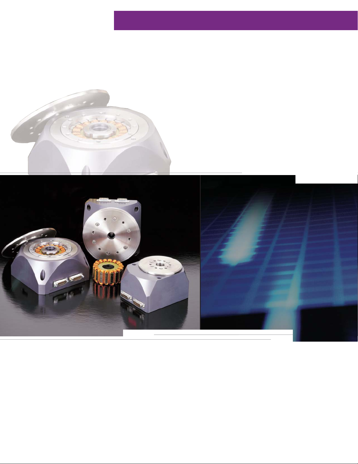
Rotary Series
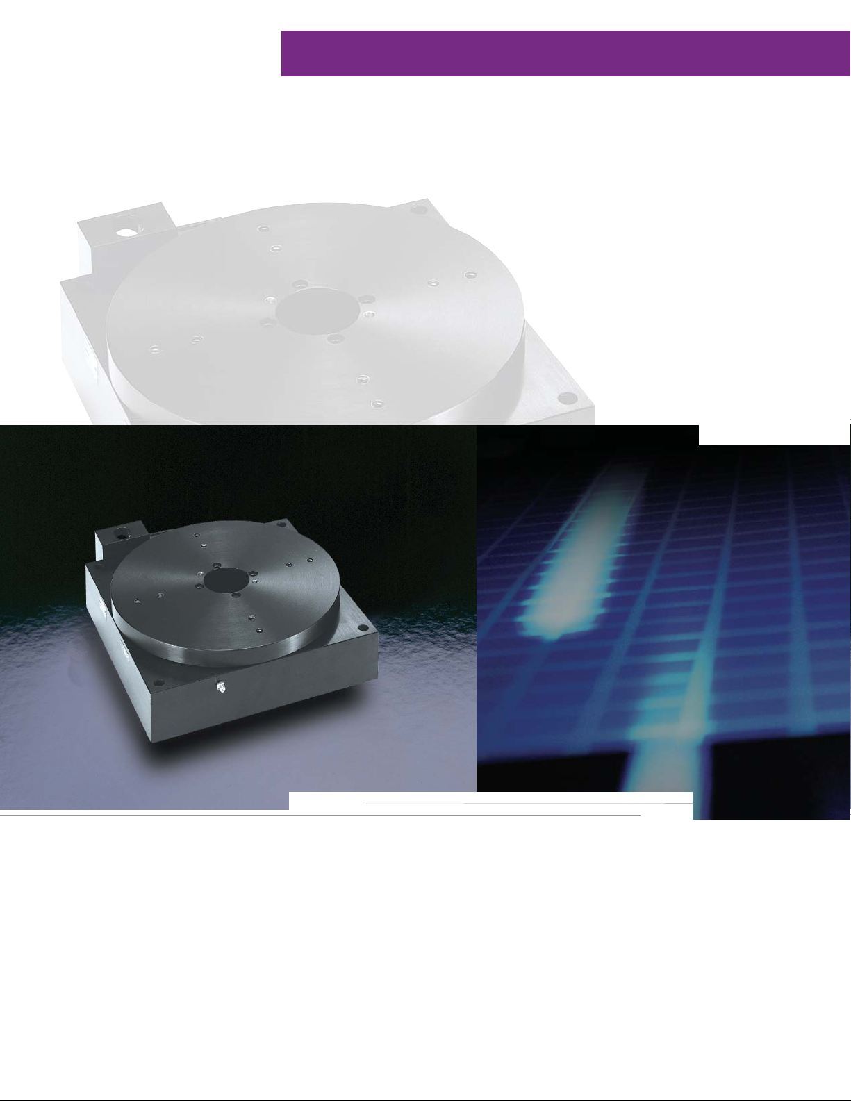
Rotary Series: Direct Drive Precision Stages
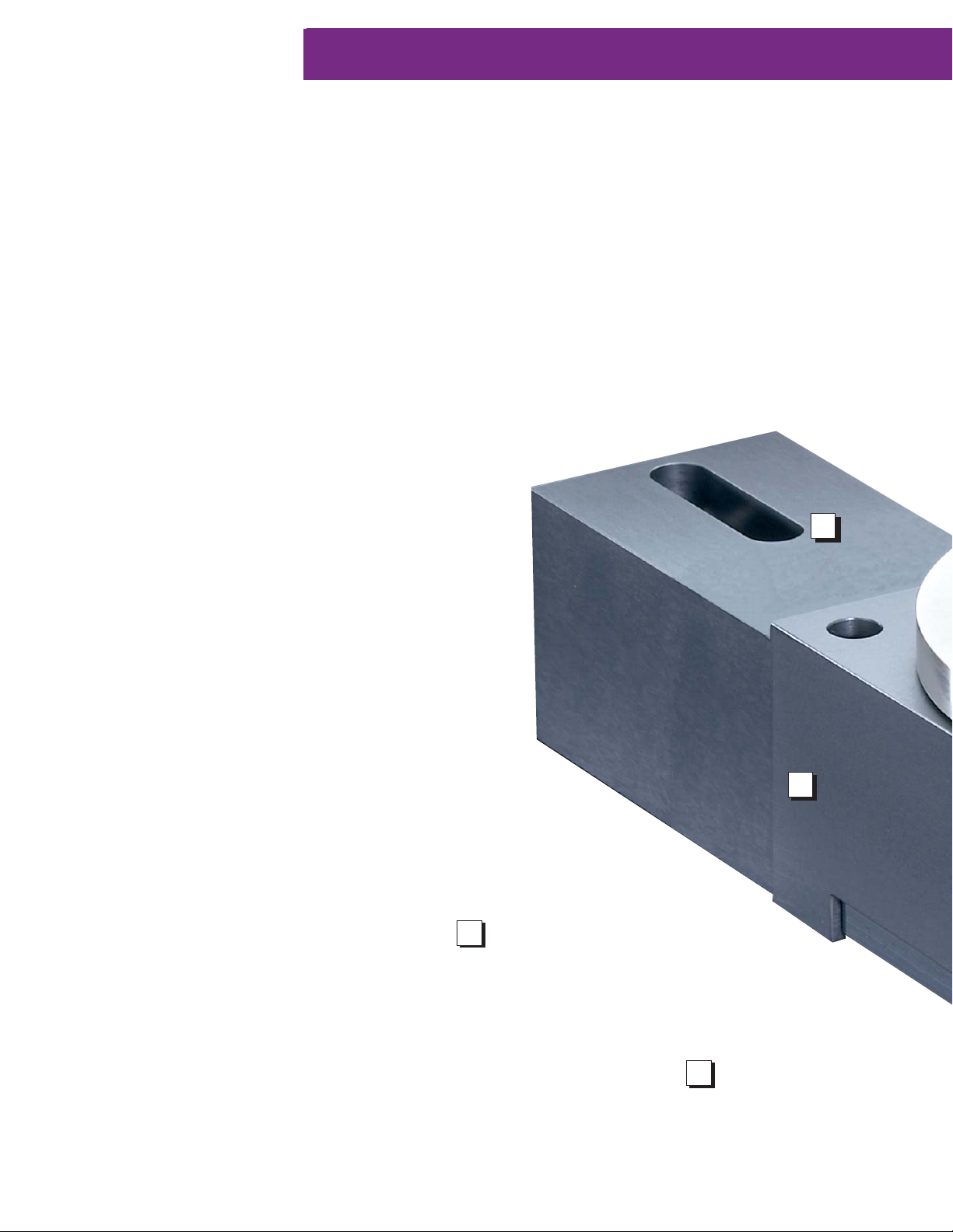
Parker Bayside’s Direct Drive Rotary
Stages feature a robust construction and
high performance in a compact package,
providing smooth, near-frictionless motion
with zero backlash.
76
Page 2
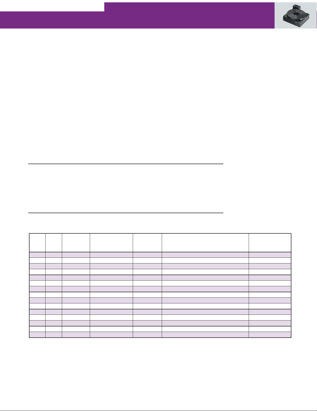
Performance Specifications
Model No. Axial Perpendicular Continuous Peak Maximum
Capacity Capacity Output Output Output
@ Radius Torque Torque Speed
(1)
(kgf) (lb) (Nm) (in lb) (Nm) (in lb) (RPM)
R100D 75 165.3 20kgf @ 50mm 0.65 5.75 1.96 17.34
R150D 150 330.6 75kgf @ 75mm 4.00 35.4 12.00 106.2 500
R200D 250 551.1 150kgf @ 100mm 6.2 54.80 18.60 164.40 300
Model No. Radial Axial Wobble
Runout Runout @ Axis Inertia Stage Weight
@ øH @ øk of Rotation
(
R100D 20 18 60 14.2 0.197 2.24 4.85
R150D 26 23 45 86.4 1.200 5.8 12.79
R200D 36 30 30 338.0 4.695 10.5 23.15
microns)
microns) (arc sec) (gm cm sec2) (oz in sec2) (kg) (lb)
(
700
Encoder Data
Model No. R100D R150D R200D
Total Number of counts/rev
Frequency at Max Speed
Resolution after x4 (arc sec) 2.73 2.05 1.3728
Repeatability after x4 (arc sec)
(2)
473,600 629,760 944,000
(2)
(MHz) 5.5 5.2 4.7
(3)
± 8.4 ± 6.15 ± 4.1
(1) Maximum speed may be limited by input frequency response of controller or drive.
(2) Post quadrature (includes 10x interpolation and 4x of control).
(3) Typical system repeatability that can be achieved by a closed loop control system.
Motor Specifications
Model No. Voltage Constant Torque Constant
K
(V/kRPM) (Nm/amp) (in lb/amp) (
R100D 75 0.72 6.37 59.9 50 2.0
R150D
R200D
Model No. Rated Voltage Icont
(V) (amps) (amps) (
R100D 300 0.9 2.72
R150D
R200D
K
EL-L
210 2
325 3.1
300 2.0 6.0 5 V @ 170 ma 20
300 2.0 6.0 5 V @ 170 ma
17.7
27.4
R
TL-L
11.4 14 2.0
10.4 21 2.0
Ipeak
Resistance
ohms@ 25°C)
L
L-L
(mH) (
Inductance Thermal
L-L
Logic Voltage Pole Count
V/amp)
5 V @ 170 ma
12
32
Resistance
°C/W)
77
Page 3
Rotary Series
Direct Drive Precision Stages
High Performance in a Compact Package
Parker Bayside's Direct Drive Rotary Stage, featuring an integral brushless
DC servomotor, has several distinct advantages over traditional worm
gear-driven stages. The elimination of the worm gearing offers the ability to
reduce wear with zero backlash while exhibiting near frictionless motion.
Its high positioning accuracy, solely based on the stage's encoder, provides
repeatability within + 2 encoder counts, with resolutions ranging to 1.4
arc seconds. The RD Direct Drive features speeds up to 700 RPM with
significant torque capability.
When to Use:
Precision rotary motion
ZERO backlash
Compact
Rugged
Applications:
Electronic assembly
Fiber Optics
Medical
Packaging
Pharmaceutical
Robotics
Semiconductor
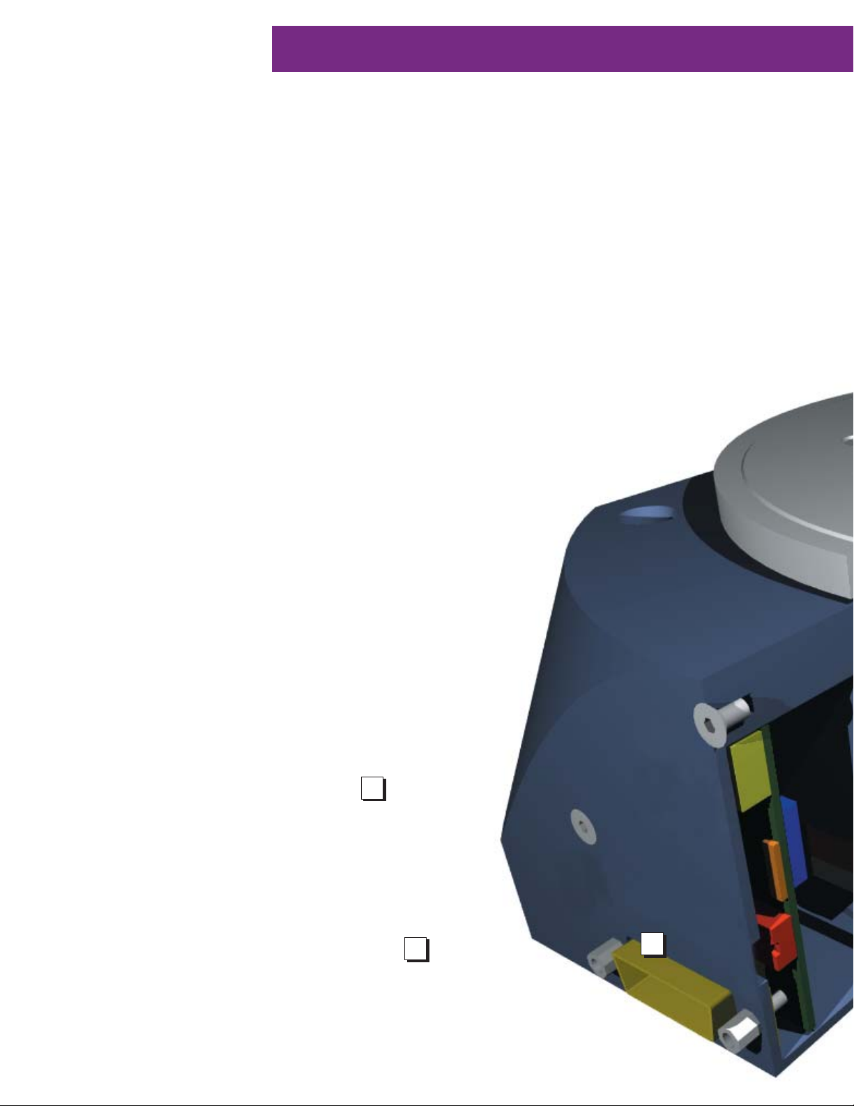
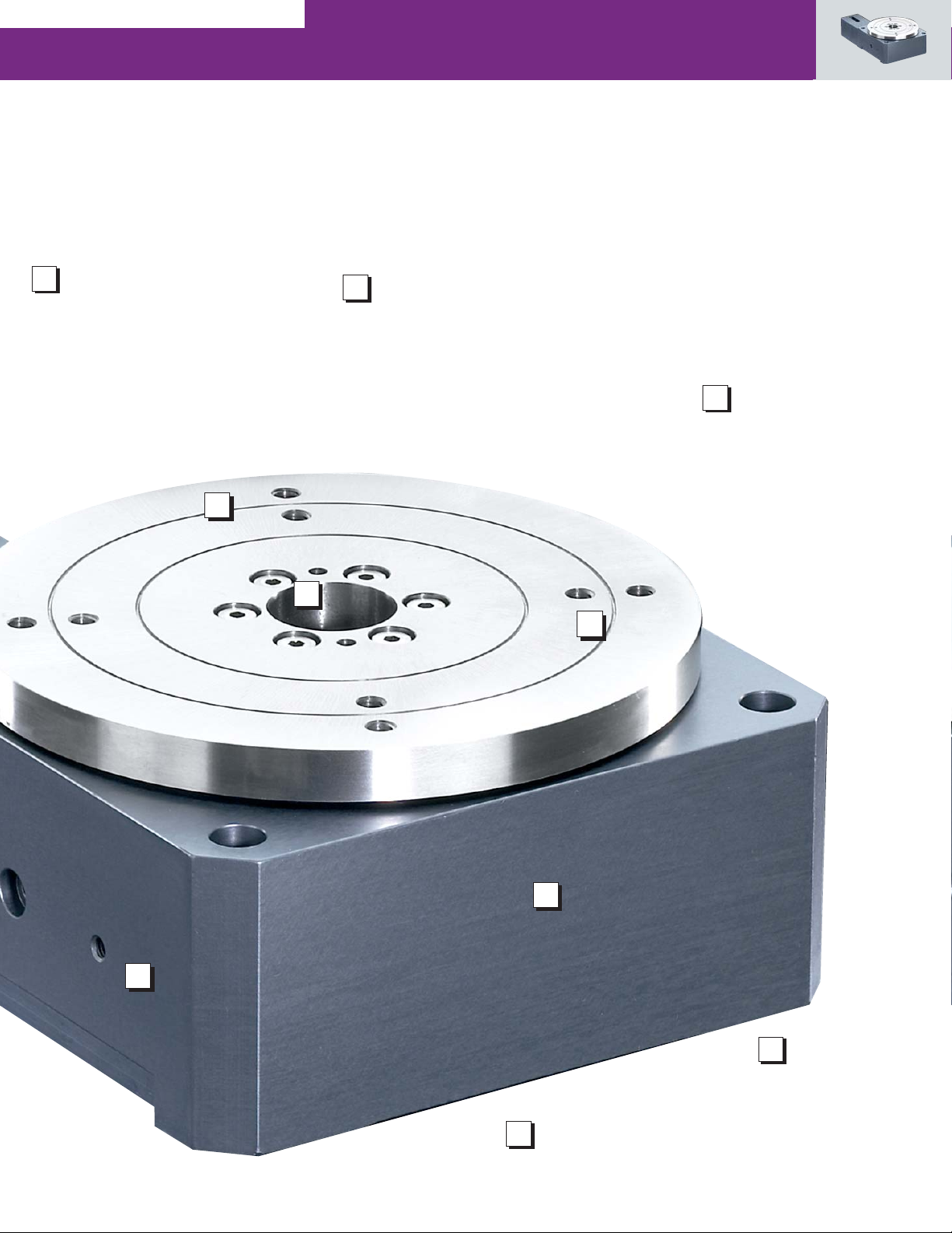
1
Robust bearing design
for high load capacity
78
2
Rotor / Shaft
motor rotor and top plate shaft
as one piece construction for
high stiffness
6
Page 4
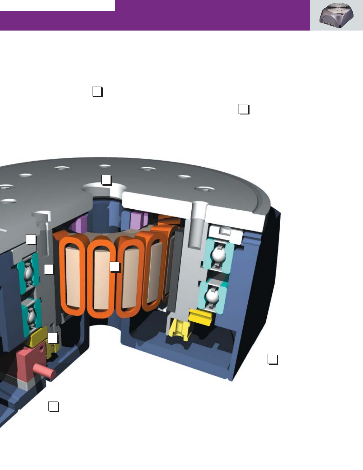
3
Stainless Steel Top
Plate
precision ground for
accurate mounting
4
Integrated Brushless
Motor
unique design with high copper
slot and rare earth magnet for
maximum torque efficiency
3
1
2
5
6
Sub “D” connectors
for “plug & play” operation
and easy hook-up.
4
5
Inline Rotary
Encoder for direct
position feedback. Also
includes once per rev index
mark
79
Page 5
Rotary Series
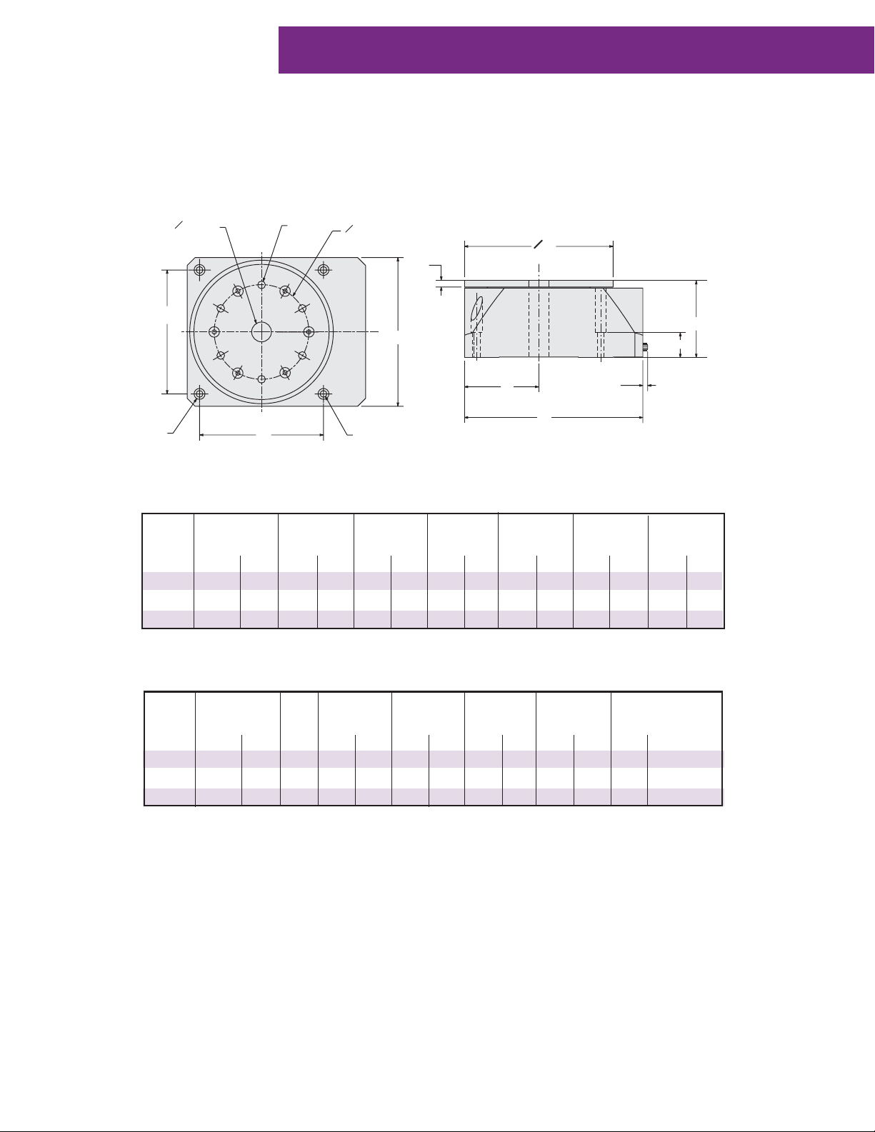
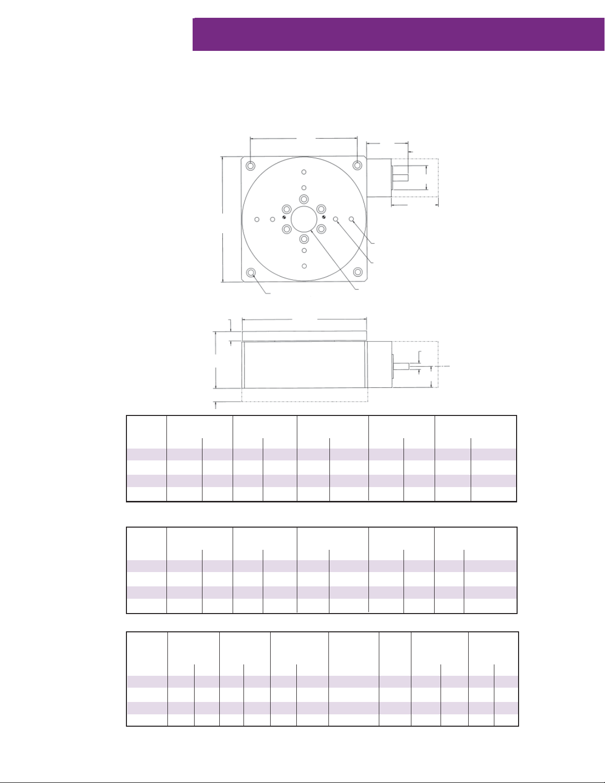
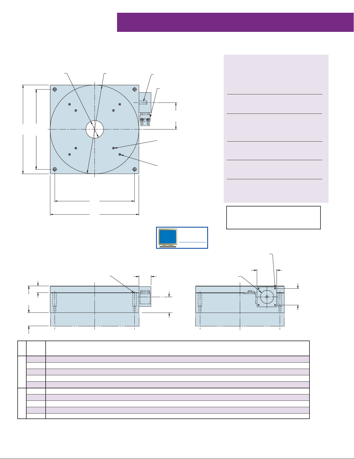
Dimensions
Direct Drive Precision Stages
O H (h6)
G
H
Model No. A B C D E F G
(mm) (in) (mm) (in) (mm) (in) (mm) (in) (mm) (in) (mm) (in) (mm) (in)
R100D 100 3.94 100 3.94 75 2.95 130 5.12 50 1.96 5 0.196 85 3.34
R150D 150 5.9 150 5.9 78 3.07 180 7.08 75 2.95 7 0.275 125 4.92
R200D 200 7.87 200 7.87 100 3.94 230 9.05 100 3.94 10 0.393 160 6.29
J
G
O K
O A
F
B
E
D
L
P
C
N
Model No. H J K L M N P
(mm) (in) Tap (mm) (in) (mm) (in) (mm) (in) (mm) (in) (mm) (in)
R100D 20 0.787 M5 60 2.36 5.5 0.216 9.5 0.374 25 0.984 5 0.196
R150D 20 0.787 M6 95 3.74 6.5 0.255 11.2 0.440 25 0.984 5 0.196
R200D 30 1.18 M8 125 4.92 8.5 0.334 14.0 0.551 25 0.984 5 0.196
Page 6
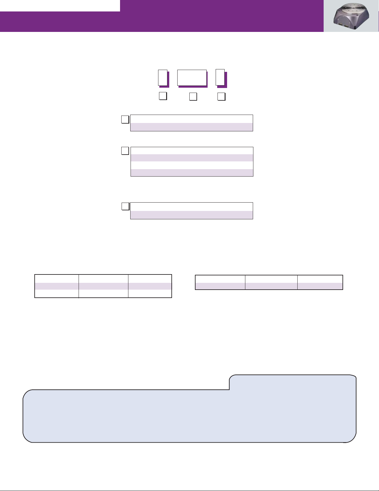
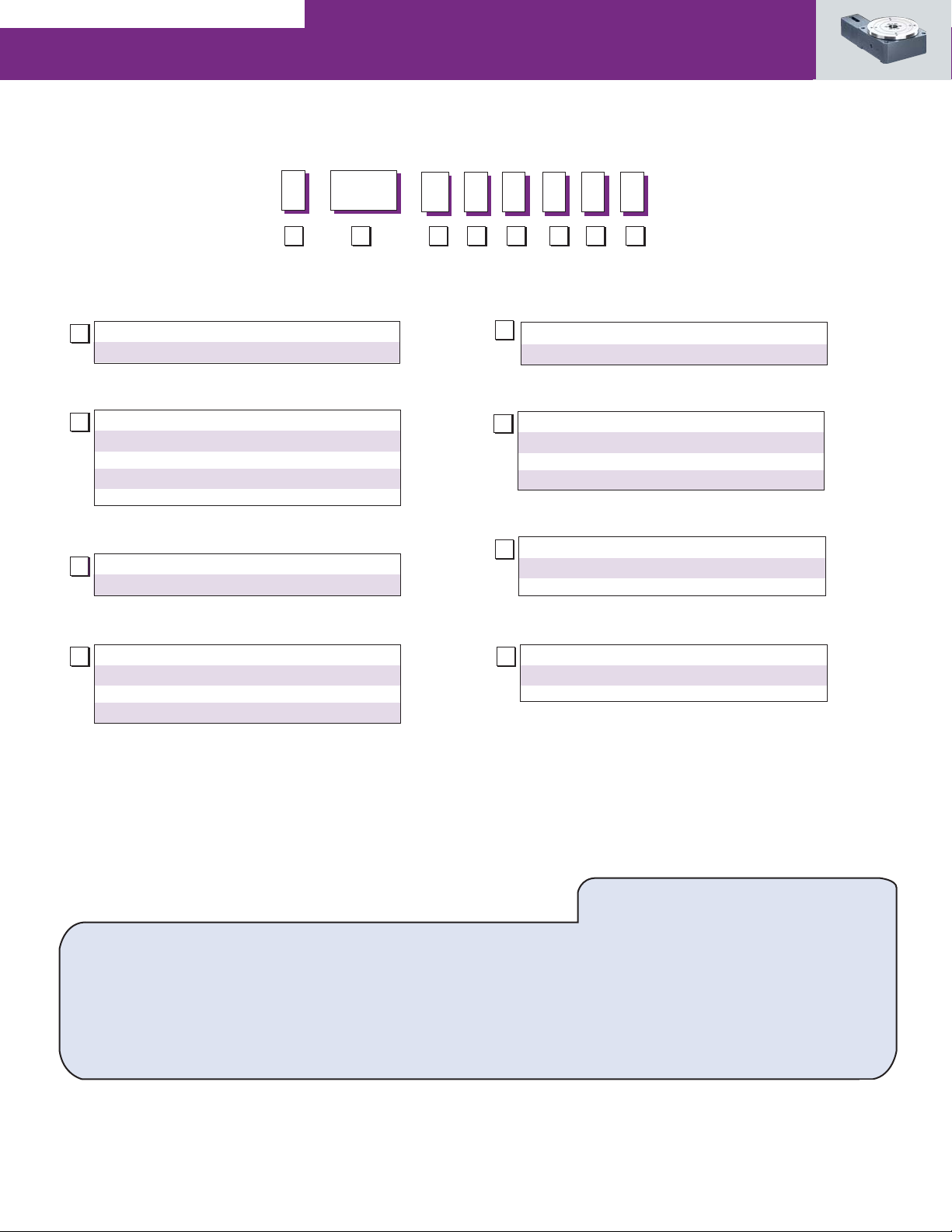
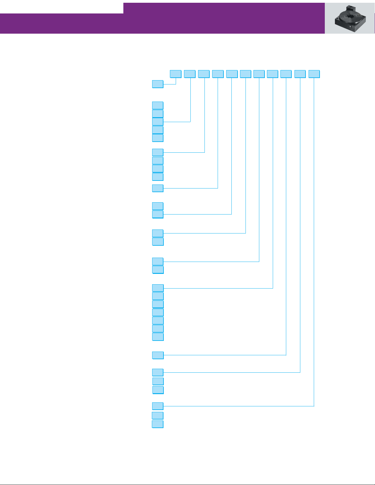
Order Numbering
Example:
How to Order
150R
D
A
STAGE SERIES
A
R Direct Drive Rotary
MODEL
B
100 100 mm
150 150 mm
200 200 mm
C
DRIVE
D Direct Drive
Cable Options:
Mating Power Cable
Part Number Length Used With
10963018-3000 3 meters Flying Leads
10963018-8000 8 meters Flying Leads
“Only for use with stage versions without LC display and programmable
limits/outputs 5v requirement and Y-cable limits branch of previous cable
type”
B C
Mating Sensor Cable
Part Number Length Used With
10963241-3000 3 meters Flying Leads
Direct Drive Rotary Stages are supported by a worldwide network of offices and local distributors.
Call 1-800-305-4555 for application engineering assistance or for the name of your local distributor.
Information can also be obtained at www.baysidemotion.com or www.parkermotion.com.
Specifications are subject to change without notice.
How to Order
81
Page 7
Rotary Series
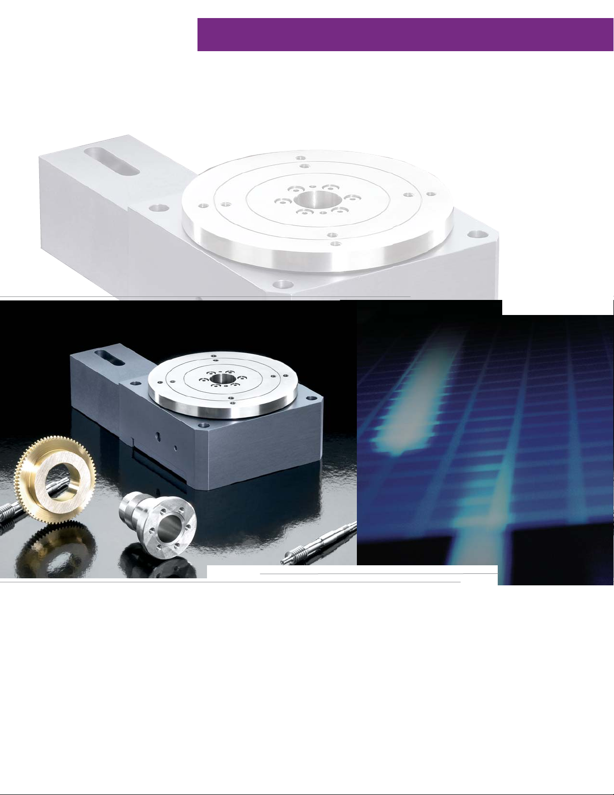
Rotary Series: Worm Drive Precision Stages
Parker Bayside’s Worm Drive Precision
Stages feature a unique self-compensating
preload to limit backlash, solid or though-bore
construction, and built-in limit switches.
82
Page 8
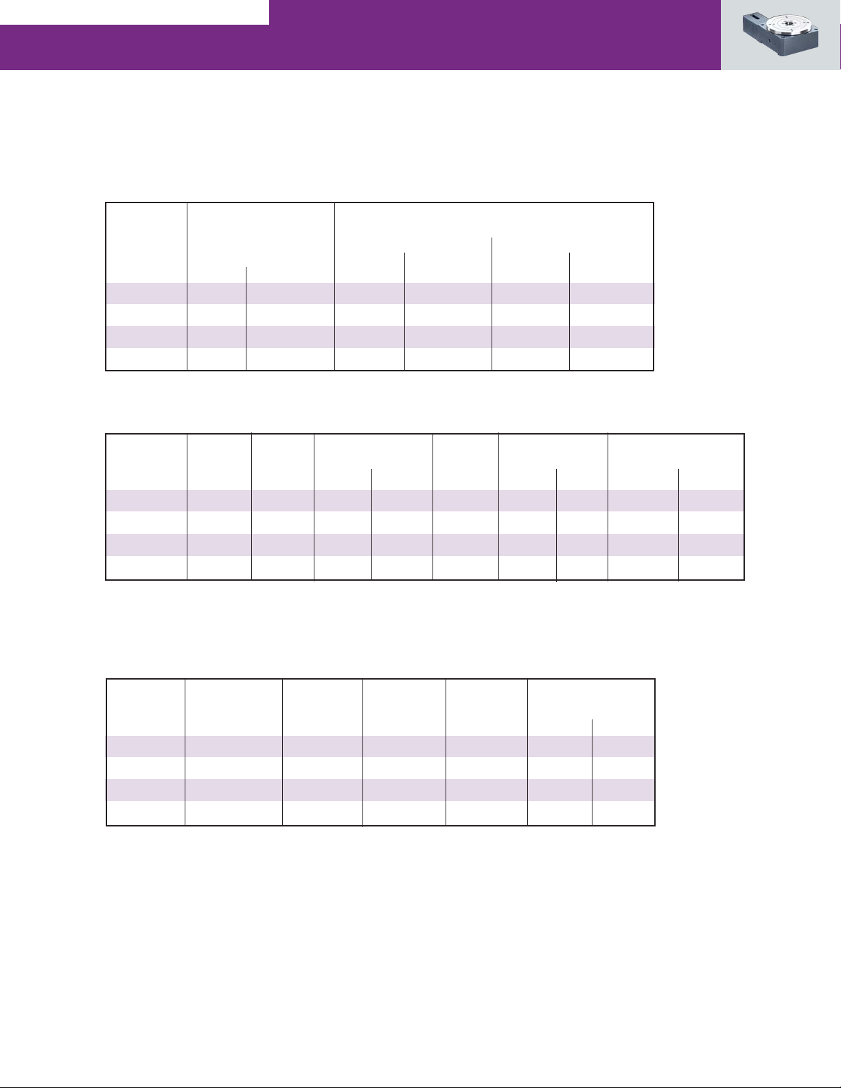
Performance Specifications
Model No. Axial Perpendicular
Capacity Capacity
@ 25mm @ 150mm
(kg) (lb) (kgf) (lb) (kgf) (lb)
R100M 100 220 22 48 7 15
R150M 400 880 88 194 33 73
4
600 1,320 200 440 85 187
R200M
R300M 1,000 2,220 325 715 160 352
Model No. Worm Gear Gearing Peak Output Torque Peak Output Weight Inertia
Ratio Backlash
(arc sec) (Nm) (in lb) (RPM) (kgf) (lbf) (gm cm sec2) (oz in sec2)
R100M 60:1 2 8 70.8 30 2.3 5.0 0.0057 0.0000784
R150M 72:1 2 25 221 30 6.0 13.0 0.055 0.00076
4
72:1 2 55 487 30 15.0 33.0 0.148 0.00210
R200M
R300M 90:1 2 75 664 30 35.0 77.0 0.368 0.00516
Accuracy Specifications
Runout Parallelism Accuracy Repeatability
(microns) (microns) (arc min) (arc sec) (Nm) (in oz)
R100M ±
R150M ±
R200M 4 ±7 ±
R300M ±
Main Bearing Top to Base Position
Model No.
(2)
5
5
10
(1)
@100RPM Input Speed
(3)
Position
±
12 2 12 0.07
±
12 2 12 0.14
17 2 12 0.14
±
25 2 12 0.21
(3)
Input Torque
Required
20
20
20
30
(1) Gearing backlash is uni-directional.
(2) Accuracy is based on stage mounted to a flat granite surface and measured at 25mm above the center of the stage.
(3) Accuracy and repeatability are based on open loop lead accuracy and can be enhanced with encoder feedback.
(4) See 200 RT Series page 90.
83
Page 9
Rotary Series
Worm Drive Precision Stages
The Rotary Stage Series offers an unparalleled combination of
high accuracy and high-load capacity.
These rotary stages utilize a precision worm gear with the worm
“flexed” against the gear to ensure a proper mesh. This feature
provides high repeatability with very smooth operation.
Additionally, the rotary stages incorporate an oversized preloaded
crossed roller bearing, offering exceptional stiffness and load
capacity.
Unique self-compensating preload to limit backlash
Solid or thru bore construction
Robust bearing design for high-load capacity
Built-in limit switches
Aluminum construction with stainless steel top plate
When to Use:
High accuracy
High loads
Compact
High stiffness
Applications:
Electronic assembly
Fiber Optics
Medical
Packaging
Pharmaceutical
Robotics
Semiconductor
l
7
7
Heavy Duty Stainless Steel Worm
with Bronze Gear
for smooth operation and high torque and
Self-Compensating Preload for zero
backlash
84
6
Completely Sealed
and Lubricated
for long life even in harsh environments
Page 10
l
Motor Mounting and
Coupling
for easy installation
2
Integral Limit Switches
mounted under top plate for safety
3
Preloaded Crossed
Roller Bearings
for high loads and
spindle stiffness
2
3
4
5
6
4
Stainless Steel Top
Plate
with solid or through
5
Optional Inline
Rotary Encoder
for direct position feedback
hole construction
85
Page 11
Rotary Series
Dimensions
Motor Mounting
D
B
P HOLES ON A N BCD
P HOLES ON A M BCD
Bracket
H
G
K
S
(1) This dimension is used when the
in-line encoder option is selected.
Model No. A B C D E
(mm) (in) (mm) (in) (mm) (in) (mm) (in) (mm) (in)
R100M 98.5 3.88 100 3.94 55 2.16 85 3.35 8 0.32
R150M 147.6 5.81 150 5.90 75 2.95 125 4.92 11 0.43
R200M 197.7 7.78 200 7.87 90 3.54 170 6.70 15 0.59
R300M 297.7 11.72 300 11.81 108 4.25 270 10.63 16 0.63
Model No. F G H J K
(mm) (in) (mm) (in) (mm) (in) (mm) (in) (mm) (in)
R100M 12 0.47 15 0.59 45 1.77 5 0.197 18 0.709
R150M 25.5 1.00 27 1.06 66 2.60 10 0.394 38.1 1.50
R200M 38 1.50 27 1.06 66 2.60 10 0.394 38.1 1.50
R300M 51 2.00 39 1.53 113 4.45 12 0.472 73 2.875
C
50 (1)
R COUNTERBORE
FOR MOUNTING SCREWS
E
A DIA
F DIA. THRU
J
L
Model No. L M N P R S Stage
Weight
(mm) (in) (mm) (in) (mm) (in) Tap C'Bore (mm) (in) (kg) (lb)
R100M 21 0.83 45 1.772 75 2.953 M5 x 0.8 M5 38.1 1.50 1.8 3.97
R150M 30.1 1.18 100 3.937 125 4.921 M6 x 1 M6 60.2 2.37 5 11
R200M 33.5 1.32 100 3.937 150 5.905 M8 x 1.25 M8 60.2 2.37 13 28.66
R300M 44.2 1.74 150 5.905 250 9.843 M8 x 1.25 M8 73.1 2.88 29 63.93
Page 12
Order Numbering
Example:
150
A B C D E F G H
MR3 2 2 1 2
How to Order
STAGE SERIES
A
R Worm Gear Rotary Series
METRIC SQUARE WIDTH
B
100 100mm
150 150mm
200 1 200mm
300 300mm
DRIVE
C
M Separate Motor
GEAR RATIO
D
2 60:1 (R100)
3 72:1 (R150 and R200)
4 90:1 (R300)
(1) See page 90 for 200RT series and page 127 for manual
driven rotary positioning stages
E
MOTOR MOUNTING
X See how to order step 2
LIMIT SWITCHES
F
1 None
2 End of Travel
3 End of Travel and Home
ENCODER IN LINE WITH TOP PLATE
G
1 None
3 2000 LPR
ENVIRONMENT
H
1 Standard
2 Clean Room
How to Order
1. Pick features and options above.
2. Specify motor, make and model for mounting kit.
Parker Bayside’s Rotary Series is supported by a worldwide network of offices and local distributors. Call 1-800-305-4555 for application
engineering assistance and the name of the local distributor or Parker Bayside office nearest you. Visit us online at www.baysidemotion.com or
www.parkermotion.com for product information.
Specifications are subject to change without notice.
87
Page 13
Rotary Series
200 RT Series: Rotary Tables
• High repeatable indexing (12 arc sec.)
• Load capacities to 200 lbs
• 360 degrees travel
• Performance tested worm gear drive
• Selectable table sizes and drive ratio
• Dual race angular contact support bearing
Page 14
200 RT Series: Overview
Quality Design and Construction
The 200RT Series Rotary Tables are designed for precise motor-driven rotary
positioning and indexing. These tables are designed to function independently
found in virtually all industries where intermittent part indexing, part scanning,
skew adjustment, or precise angular alignment is required.
or in conjunction with linear tables used in high precision and precision
automation applications. Their low-profi le design minimizes stack height in
multi-axis confi gurations and enables them to fi t in many places where other
motorized rotary devices cannot.
At the heart of these tables is a rugged main support bearing which is com-
prised of two preloaded angular contact bearing races. It is designed for high
load capacity and smooth, fl at rotary motion. The drive is a precision worm
gear assembly that is preloaded to remove backlash. The top and base are
Models are available in 5, 6, 8, 10, or 12 inch diameters and are offered with
four gear ratios making it convenient to match size, speed, and load require-
constructed of high quality aluminum with an attractive black anodized fi nish.
The top and bottom mounting surfaces are precision ground to assure fl atness.
ments. They can be selected in either English or Metric mounting. They are
200RT Series Characteristics
Common Characteristics Units Precision Standard
Performance
Positional Repeatability arc min 0.2 0.5
(unidirectional)
Duty Cycle % 50 50
Table Runout (Max.) in (µm) ±0.001 (±25) ±0.003 (±75)
Concentricity in (µm) ±0.001 (±25) ±0.005 (±127)
Wobble arc sec. 30 60
Input Velocity (Max.) revs./sec. 15 15
Travel Dependent Characteristics
Input
Table Drive Load Accuracy Output Inertia Breakaway Running Weight
Diameter Ratio Capacity Prec. Std. Torque 10
inches lbs. (kgf) arc min in-lb (N-m) (10
5.0 180:1 25 (11) 3 10 25 (2.8) 0.14 (0.102) 22 (0.16) 20 (0.13) 0.67 (0.3) 6.0 (2.7)
5.0 90:1 25 (11) 3 10 25 (2.8) 0.15 (0.112) 22 (0.16) 20 (0.13) 0.67 (0.3) 6.0 (2.7)
5.0 36:1 70 (32) 5 12 25 (2.8) 0.24 (0.173) 22 (0.16) 20 (0.13) 0.67 (0.3) 6.0 (3.6)
6.0 180:1 150 (68) 3 10 40 (4.5) 0.16 (0.112) 22 (0.16) 20 (0.13) 0.91 (0.42) 8.0 (2.7)
6.0 90:1 150 (68) 3 10 40 (4.5) 0.20 (0.132) 22 (0.16) 20 (0.13) 0.91 (0.42) 8.0 (3.6)
6.0 45:1 150 (68) 5 12 40 (4.5) 0.29 (0.204) 22 (0.16) 20 (0.13) 0.91 (0.42) 8.0 (3.6)
8.0 180:1 150 (68) 3 10 40 (4.5) 0.24 (0.163) 28 (0.19) 25 (0.18) 2.23 (1.01) 15.0 (6.8)
8.0 90:1 150 (68) 3 10 40 (4.5) 0.66 (0.459) 28 (0.19) 25 (0.18) 2.23 (1.01) 15.0 (6.8)
8.0 36:1 150 (68) 5 12 40 (4.5) 0.90 (0.642) 28 (0.19) 25 (0.18) 2.30 (1.05) 15.0 (6.8)
10.0 180:1 200 (90) 3 10 190 (21.5) 0.74 (0.530) 33 (0.22) 30 (0.21) 5.26 (2.30) 29.0 (13.1)
10.0 90:1 200 (90) 3 10 190 (21.5) 1.02 (0.734) 33 (0.22) 30 (0.21) 5.26 (2.30) 29.0 (13.1)
10.0 45:1 200 (90) 5 12 190 (21.5) 2.13 (1.53) 33 (0.22) 30 (0.21) 5.26 (2.30) 29.0 (13.1)
12.0 180:1 200 (90) 3 10 190 (21.5) 0.99 (0.713) 33 (0.22) 30 (0.21) 7.67 (3.49) 32.0 (14.5)
12.0 90:1 200 (90) 3 10 190 (21.5) 1.59 (1.12) 33 (0.22) 30 (0.21) 7.67 (3.49) 32.0 (14.5)
12.0 45:1 200 (90) 5 12 190 (21.5) 3.83 (2.75) 33 (0.22) 30 (0.21) 7.67 (3.49) 32.0 (14.5)
NOTE: For moment load calculations, refer to the technical section of Parker’s web site www.parkermotion.com
-3
oz-in.-sec2 Torque (max) Torque (max) Std. Top Total
-6
kg-m-sec2) oz-in (N-m) oz-in (N-m) lb (kgf) lb (kgf)
Rotary Encoder Option:
High resolution, high accuracy ring encoders can be mounted
to the base of the rotary table. The encoder is coupled directly to the rotary
table top, providing positional feedback with no drive train errors. 314,880 or
3,148,800 post quadrature counts per revolution are available, and an encoder
housing is included to enclose and protect the encoder.
89
Page 15
Rotary Series
2D & 3D
CAD
Dimensions inch (mm)
"B" dia.
thru hole
D
C
ctr'd
D
ctr'd
C
"A" dia.
table top
Drive Screw Shaft
205RT - 0.250 dia. (6.4 mm)
206-212RT - 0.188 dia. (4.78 mm)
Home Option
H
4 mtg. holes (top)
on a "J" dia b.c.
English models = 1/4-20 thd.
Metric models = M6 thd.
4 mtg. holes (top)
on a "K" dia b.c.
English models = 1/4-20 thd.
Metric models = M6 thd.
Options:
Motor Couplings
A wide range of coupling styles and bores are available to match
motor requirements. Bellows-style couplings, offering the lowest
windup are required for all precision grade tables, while the
aluminum and stainless steel helix couplers offer good windup
characteristics and high durability at a lower cost.
Motor Mounts
The motor mount is designed for an industry standard
motor fl ange and a maximum shaft length of 0.85”.
Home Sensor
The Home sensor provides a fi xed reference point to which the
table can always return. This is a mechanical reed switch which
is mounted the body of the rotary table and is activated by a
magnet imbedded on the table top.
Rotary Encoders
High accuracy rotary encoders can be added for direct positional
feedback of the table top position.
Seals
Custom designed sealed units are offered to prevent excessive
wear or internal damage resulting from dust and contaminates.
Motors, Drives & Controls
Micro-step motors with drives are available for direct mounting
to the rotary tables. Motion controllers can also be added to
provide systems with seamless connectivity.
NOTE: Refer to www.parkermotion.com or contact a
Parker applications engineer for additional detailed
information pertaining to any of these options or
accessories.
NEMA 23
Download from
parkermotion.com
files
English models = #10-32 thd.
4 c'bored mtg. holes (base)
English models = 1/4 S.H.C.S.
Metric models = M6 S.H.C.S.
F
E
1.00
(Encoder Option)
A B C D E F G H J K L M
Std. (T2) Option (T3) Std. (T2) Option (T3)
5.0 1.0 5.0 4.0 1.8 2.42 0.38 1.00 1.11 1.66 3.0 4.0 1.38 0.188
6.0 1.75 6.0 5.0 2.0 2.62 0.38 1.00 1.23 2.04 4.0 5.0 1.38 0.250
8.0 1.75* 8.0 6.0 2.5 3.00 0.50 1.00 1.57 2.04 4.0 6.0 1.38 0.250
English
10.0 2.0 10.0 9.0 3.0 3.25 0.75 1.00 1.81 3.03 6.0 8.0 1.38 0.250
12.0 2.0 10.0 9.0 3.0 3.25 0.75 1.00 1.81 3.03 8.0 10.0 2.38 0.250
127.0 25.4 127.0 100 46.0 61.5 9.6 25.4 28.1 42.1 75 100 35 4.76
152.4 44.5 152.4 125 50.8 66.5 9.6 25.4 31.4 51.8 100 125 35 6.35
202.4 44.5* 203.2 175 63.5 76.2 12.7 25.4 39.8 51.8 100 150 35 6.35
Metric
254.0 50.8 254.0 225 76.2 82.6 19.0 25.4 45.9 76.9 150 200 35 6.35
304.8 50.8 254.0 225 76.2 82.6 19.0 25.4 45.9 76.9 200 250 60.4 6.35
*On the 8.0” (203,2) diameter table with 36:1 ratio, this dimension is 1.0” (25,4).
L
G
Metric models = M5 thd.
1.50 (38.1) dia.
Motor Pilot
4 mtg. holes
(57.2)
square
2.25
1.86
(47.2)
square
Page 16
Model Series
2
Table Diameter
5 in 127 mm ...................................................
6 in 152.4 mm .................................................
8 in 202.4 mm .................................................
10 in 254 mm ....................................................
12 in 304.8 mm ..................... ...........................
05
06
08
10
12
Gear Ratio
180:1 (Avail. on all dia.) .............................................
90:1 (Avail. on all dia.) .............................................
45:1 (Avail. on 6”, 10” and 12” dia. only)
36:1 (Avail. on 5” and 8” dia. only) ..............
Table Style.....................................................................
01
02
04
05
RT
Mounting
English ......................................................................................
Metric ..............................................................................
E
M
Grade
Standard Grade ................................................................
Precision Grade ...............................................................
S
P
Home
No Home Switch ..............................................................
Magnetic Home Switch ....................................................
H1
H2
Motor Coupling
No Coupling ...................................................................
0.25 in Bore, Helix, Aluminum ..........................................
0.25 in Bore, Helix, Stainless Steel ...................................
0.25 in Bore, Bellows, required for precision grade
0.375 in Bore, Helix, Aluminum ........................................
0.375 in Bore, Helix, Stainless Steel .................................
0.375 in Bore, Bellows, required for precision grade ..............
..............
C1
C2
C3
(Not Available on 205 Model)
C4
C5
C6
(Not Available on 205 Model)
C7
Motor Mount
How to Order
Order Example
E1
08 01 RT M H1 C1 M1S2
T1
23 Frame Size .................................................................
M1
Encoder
No Encoder ...................................................................
Ring Encoder - 314,880 post quad. counts/rev. ................
Ring Encoder - 3,148,800 post quad. counts/rev. .............
E0
E8
E9
Table Top
No Top .............................................................................
Standard Top ......................................................................
Oversized Top (Raises height to clear NEMA 23 Motor)..... ........
T1
T2
T3
91
 Loading...