

Page 1

AMX-8952 Series User Guide
Page 2

Thank You for Choosing Ross
You've made a great choice. We expect you will be very happy with your purchase of Ross
Technology.
Our mission is to:
1. Provide a Superior Customer Experience
• offer the best product quality and support
2. Make Cool Practical Technology
• develop great products that customers love
Ross has become well known for the Ross Video Code of Ethics. It guides our interactions and
empowers our employees. I hope you enjoy reading it below.
If anything at all with your Ross experience does not live up to your expectations be sure to reach
out to us at [email protected].
David Ross
CEO, Ross Video
Ross Video Code of Ethics
Any company is the sum total of the people that make things happen. At Ross, our employees are a
special group. Our employees truly care about doing a great job and delivering a high quality
customer experience every day. This code of ethics hangs on the wall of all Ross Video locations to
guide our behavior:
1. We will always act in our customers’ best interest.
2. We will do our best to understand our customers’ requirements.
3. We will not ship crap.
4. We will be great to work with.
5. We will do something extra for our customers, as an apology, when something big goes wrong
and it's our fault.
6. We will keep our promises.
7. We will treat the competition with respect.
8. We will cooperate with and help other friendly companies.
9. We will go above and beyond in times of crisis. If there's no one to authorize the required action in
times of company or customer crisis - do what you know in your heart is right. (You may rent
helicopters if necessary.)
Page 3

AMX-8952 Series · User Guide
• Ross Part Number: 8952DR-004-05
• Software Version: 1.2
• Release Date: October 21, 2022.
The information contained in this Guide is subject to change without notice or obligation.
Copyright
©2022 Ross Video Limited, Ross®, and any related marks are trademarks or registered trademarks
of Ross Video Limited. All other trademarks are the property of their respective companies.
PATENTS ISSUED and PENDING. All rights reserved. No part of this publication may be reproduced,
stored in a retrieval system, or transmitted in any form or by any means, mechanical, photocopying,
recording or otherwise, without the prior written permission of Ross Video. While every precaution
has been taken in the preparation of this document, Ross Video assumes no responsibility for
errors or omissions. Neither is any liability assumed for damages resulting from the use of the
information contained herein.
Patents
Patent numbers US 7,034,886; US 7,508,455; US 7,602,446; US 7,802,802 B2; US 7,834,886; US
7,914,332; US 8,307,284; US 8,407,374 B2; US 8,499,019 B2; US 8,519,949 B2; US 8,743,292 B2; GB
2,419,119 B; GB 2,447,380 B; and other patents pending.
Notice
The material in this manual is furnished for informational use only. It is subject to change without
notice and should not be construed as commitment by Ross Video Limited. Ross Video Limited
assumes no responsibility or liability for errors or inaccuracies that may appear in this manual.
Safety Notices
Refer to the “Important Regulatory and Safety Notices” document that accompanied your
product.
Statement of Compliance
This product has been determined to be compliant with the applicable standards, regulations, and
directives for the countries where the product is marketed.
Compliance documentation, such as certification or Declaration of Compliance for the product is
available upon request by contacting [email protected]. Please include the product;
model number identifiers and serial number and country that compliance information is needed in
request.
EMC Notices
US FCC Part 15
This equipment has been tested and found to comply with the limits for a class A Digital device,
pursuant to part 15 of the FCC Rules.
Page 4
These limits are designed to provide reasonable protection against harmful interference when the
Type of Equipment User’s Guide
A
(߶הࡈ ؏ܞݦࢢ)
Class A Equipment
(Industrial Broadcasting &
Communication Equipment)
ࢇ Е ߶הࡈ(A) ࢷળࢶଢԻ۰ શ
ӖЕ یࡈЕ ࢇ ࢺࡶ ࣯ࢂଜݤ Ԃ
ֲ, ɼࢽ࠹ࢂ ࠇ߾۰ یࡈଜЕ ʨࡶ ּࢶࡳԻ
ଢТЬ.
This equipment is Industrial (Class A)
electromagnetic wave suitability equipment and
seller or user should take notice of it, and this
equipment is to be used in the places except for home.
equipment is operated in a Commercial environment. This equipment generates, uses, and can
radiate radio frequency energy and, if not installed and used in accordance with the instruction
manual, may cause harmful interference to radio communications. Operation of this equipment in
a residential area is likely to cause harmful interference in which case the user will be required to
correct the interference at his own expense.
Notice — Changes or modifications to this equipment not expressly approved by Ross Video Ltd. could
void the user’s authority to operate this equipment.
Canada
This Class “A” digital apparatus complies with Canadian ICES-003 and part 15 of the FCC Rules.
Cet appareil numerique de la classe “A” est conforme a la norme NMB-003 du Canada.
European Union
This equipment is in compliance with the essential requirements and other relevant provisions
established under regulation (EC) No 765/2008 and Decision No 768/2008/EC referred to as the
“New Legislative Framework”.
Warning — This equipment is compliant with Class A of CISPR 32. In a residential environment this
equipment may cause radio interference.
Australia/New Zealand
This equipment is in compliance with the provisions established under the Radiocommunications
Act 1992 and Radiocommunications Labeling (Electromagnetic Compatibility) Notice 2008.
Korea
This equipment is in compliance with the provisions established under the Radio Waves Act.
Class A equipment (Broadcasting and communications service for business use)
This device is a business-use (Class A) EMC-compliant device. The seller and user are advised to be
aware of this fact. This device is intended for use in areas outside home.
International
This equipment has been tested under the requirements of CISPR 22:2008 or CISPR 32:2015 and
found to comply with the limits for a Class A Digital device.
Notice — This is a Class A product. In domestic environments, this product may cause radio
interference, in which case the user may have to take adequate measures.
Page 5

Maintenance/User Serviceable Parts
Routine maintenance to this openGear product is not required. This product contains no user
serviceable parts. If the module does not appear to be working properly, please contact Technical
Support using the numbers listed under the “Contact Us” section of this manual. All openGear
products are covered by a generous 5-year warranty and will be repaired without charge for
materials or labor within this period. See “Warranty and Repair Policy” in this manual for details.
Environmental Information
The equipment may contain hazardous substances that could impact health and the environment.
To avoid the potential release of those substances into the environment and to diminish the need
for the extraction of natural resources, Ross Video encourages you to use the appropriate take-back
systems. These systems will reuse or recycle most of the materials from your end-of-life equipment
in an environmentally friendly and health conscious manner.
The crossed-out wheeled bin symbol invites you to use these systems.
If you need more information on the collection, reuse, and recycling systems, please contact your
local or regional waste administration. You can also contact Ross Video for more information on the
environmental performances of our products.
Security and Privacy
If you would like more information on how Ross Video security and privacy practices have been
applied to the AMX-8952 Series, what you should know about maintaining security of this product,
and how we can partner with you to ensure security throughout this product's life-cycle, contact
[email protected].
Ross Video has implemented reasonable administrative, technical, and physical safeguards to help
protect against security incidents and privacy breaches involving a Ross Video product provided
those products are used in accordance with Ross Video instructions for use. However, as systems
and threats evolve, no system can be protected against all vulnerabilities and we consider our
customers the most important partner in maintaining security and privacy safeguards. If you have
any concerns, we ask that you bring them to our attention, and we will investigate. Where
appropriate, we will address the issue with product changes, technical bulletins and/or responsible
disclosures to customers and regulators. Ross Video continuously strives to improve security and
privacy throughout the product life-cycle using practices such as:
• Privacy and Security by Design
• Product and Supplier Risk Assessment
• Vulnerability and Patch Management
• Secure Coding Practices and Analysis
• Vulnerability Scanning
• Access Controls appropriate to Customer Data
• Incident Response
• Clear paths for two-way communication between customers and Ross Video
If you would like to report a potential product related privacy or security issue (incident, breach, or
vulnerability), contact [email protected].
Page 6

Company Address
Ross Video Limited Ross Video Incorporated
8 John Street P.O. Box 880
Iroquois, Ontario, K0E 1K0 Ogdensburg, New York
Canada USA 13669-0880
General Business Office: (+1) 613 • 652 • 4886
Fax: (+1) 613 • 652 • 4425
Technical Support: (+1) 613 • 652 • 4886
After Hours Emergency: (+1) 613 • 349 • 0006
E-mail (Technical Support): [email protected]
E-mail (General Information): [email protected]
Website: http://www.rossvideo.com
Page 7

Contents
Introduction 11
Related Publications ................................................................................................................................ 11
Documentation Conventions .................................................................................................................. 12
Interface Elements ................................................................................................................................. 12
User Entered Text .................................................................................................................................. 12
Referenced Guides ................................................................................................................................ 12
Menu Sequences ................................................................................................................................... 12
Important Instructions .......................................................................................................................... 12
Contacting Technical Support ................................................................................................................. 12
Before You Begin 13
AMX-8952-A and AMX-8952-B Overview ............................................................................................... 13
AMX-8952-C Overview ............................................................................................................................. 14
Features ..................................................................................................................................................... 15
User Interfaces ......................................................................................................................................... 15
DashBoard Control System .................................................................................................................. 15
SNMP Monitoring and Control ............................................................................................................. 15
Hardware Overview 17
Marketing Codes Overview ..................................................................................................................... 17
Main PCB Overview .................................................................................................................................. 17
RESET Button .......................................................................................................................................... 17
Monitoring via the Card-edge .............................................................................................................. 18
Supported Rear Modules ........................................................................................................................ 19
AMX-8952-A ............................................................................................................................................ 19
AMX-8952-B ............................................................................................................................................ 20
AMX-8952-C ............................................................................................................................................ 21
Physical Installation 23
Before You Begin ...................................................................................................................................... 23
Removing the Blank Plates from the Rear Panel .................................................................................. 23
Installing the Rear Module into the openGear Frame ......................................................................... 24
Installing the AMX-8952 Card into an openGear Frame ...................................................................... 24
Cabling the Ethernet Port on the openGear Frame ............................................................................. 25
Reference Cabling .................................................................................................................................... 25
Video Cabling ............................................................................................................................................ 25
Loss of Input Failover Mode ................................................................................................................. 25
Audio Cabling ............................................................................................................................................ 25
Getting Started 27
Before You Begin ...................................................................................................................................... 27
Launching DashBoard ............................................................................................................................. 27
Accessing the AMX-8952 Interfaces in DashBoard .............................................................................. 27
Configuring the Network Settings 29
Before You Begin ...................................................................................................................................... 29
Changing the Network Settings of the AMX-8952 ................................................................................ 29
AMX-8952 Series User Guide (v5.0) Contents • i
Page 8

Licensed Features 31
License Keys Overview ............................................................................................................................. 31
Installing a License Key ............................................................................................................................ 31
Removing a License Key .......................................................................................................................... 32
Reference Setup 33
Frame Rate Compatibility ........................................................................................................................ 33
Specifying a Global Analog Reference Source ...................................................................................... 34
Monitoring the Reference Signal via DashBoard ................................................................................. 35
Video Configuration 37
Configure the SDI BI-DIR Port ................................................................................................................. 37
Specifying the Output Format and Video Source ................................................................................. 37
Enabling the Loss of Input Failover Mode ............................................................................................. 39
Specifying the Output During a Loss of Input .................................................................................... 40
Specifying the Matte Color ...................................................................................................................... 41
Configuring the Bouncing Box Test Feature ......................................................................................... 41
Frame Sync Configuration 43
Before You Begin ...................................................................................................................................... 43
Enabling Frame Sync Mode ..................................................................................................................... 43
Adjusting the Output Timing ................................................................................................................... 44
Embedded Audio Setup 47
Sample Rate Conversion ......................................................................................................................... 47
Mapping the Embedded Audio Channels ........................................................................................... 47
Proc Amps for Embedded Audio ............................................................................................................ 48
Processing the Embedded Audio Input .............................................................................................. 48
AES Setup 51
Mapping the AES Inputs and Outputs ................................................................................................... 51
Mapping the AES Signals ...................................................................................................................... 51
Mapping the AES Channels ..................................................................................................................... 51
Using the Audio Proc ............................................................................................................................... 52
Analog Audio Setup 55
Mapping the Analog Inputs and Outputs .............................................................................................. 55
Mapping the Analog Signals ................................................................................................................. 55
Mapping the Analog Channels ................................................................................................................ 55
Using the Audio Proc ............................................................................................................................... 56
Ancillary Data 59
Overview .................................................................................................................................................... 59
HANC and VANC Status ......................................................................................................................... 59
CEA-708/CEA-608 Closed Captioning ..................................................................................................... 59
CEA-608 and CEA-708 Captioning Priority .......................................................................................... 59
Other Data Types ................................................................................................................................... 60
Passing or Deleting ANC Data ................................................................................................................. 60
Configuring the GPI/Tallies 63
GPI Communication Setup ...................................................................................................................... 63
Configuring a Port as a GPI ................................................................................................................... 63
Tally Communication Setup .................................................................................................................... 64
ii • Contents AMX-8952 Series User Guide (v5.0)
Page 9

Upgrading the Software 65
DashBoard Menus 67
Global Interface ........................................................................................................................................ 67
Signal Tab ............................................................................................................................................... 67
Product Tab ............................................................................................................................................ 68
Hardware Tab ........................................................................................................................................ 69
Licensing State Tab ................................................................................................................................ 70
Setup Tab ................................................................................................................................................ 70
Network Tab ........................................................................................................................................... 72
Global Alarm Enables Tab .................................................................................................................... 73
Security Tab ............................................................................................................................................ 74
Configure Licenses Tab ......................................................................................................................... 74
AMX-8952 Interfaces ................................................................................................................................ 75
AMX-8952 Status Tab ............................................................................................................................ 75
Input Status Tab ..................................................................................................................................... 77
Config Tab ............................................................................................................................................... 80
Audio Tab ................................................................................................................................................ 82
ANC Tab .................................................................................................................................................. 85
GPI/Tally Tab .......................................................................................................................................... 86
Technical Specifications 89
Supported Video Formats ....................................................................................................................... 89
SDI Inputs Specifications ......................................................................................................................... 90
SDI Outputs Specifications ...................................................................................................................... 90
AES Specifications .................................................................................................................................... 91
AMX-8952-A ............................................................................................................................................ 91
AMX-8952-B ............................................................................................................................................ 92
Analog Specifications ............................................................................................................................... 92
AMX-8952-C ............................................................................................................................................ 92
GPIO ........................................................................................................................................................... 93
Environment ............................................................................................................................................. 93
Power ......................................................................................................................................................... 94
Software Licenses 95
BSD ............................................................................................................................................................. 95
Dual GPL .................................................................................................................................................... 95
GPL ............................................................................................................................................................. 95
LGPL ......................................................................................................................................................... 100
MIT ........................................................................................................................................................... 101
zlib ............................................................................................................................................................ 101
Service Information 103
Troubleshooting Checklist ..................................................................................................................... 103
Bootload Button .................................................................................................................................. 103
Warranty and Repair Policy ................................................................................................................... 103
Glossary 105
AMX-8952 Series User Guide (v5.0) Contents • iii
Page 10

iv • Contents AMX-8952 Series User Guide (v5.0)
Page 11

Introduction
This guide covers the installation, configuration, and use of the AMX-8952 series. The following
chapters are included:
• “Introduction” summarizes the guide and provides important terms, and conventions.
• “Before You Begin” provides general information to keep in mind before installing and
configuring your card.
• “Hardware Overview” provides a basic introduction to the hardware features including the
cabling and monitoring features of the rear module.
• “Physical Installation” provides instructions for the physical installation of the card and its rear
module, and provides information on connecting to your facility network.
• “Getting Started” provides a general overview of the user controls available on the AMX-8952.
• “Configuring the Network Settings” outlines how to update the network settings assigned to
the AMX-8952.
• “Licensed Features” outlines the available software licensed features, and how to install a
software key for a licensed feature.
• “Reference Setup” outlines how to specify a global analog reference source for your card.
• “Video Configuration” outlines how specify the output format and video source for your card,
and adjust the output timing. An overview of how to enable the Frame Sync, and the ACO
features is also provided.
• “Embedded Audio Setup” outlines how to map the embedded audio channels, insert test tones,
and set up processing of the embedded audio input.
• “AES Setup” outlines how to assign an AES port as an input or output, map the AES channels, and
apply proc amps to individual AES channels.
• “Analog Audio Setup” outlines how to assign an ANLG port as an input or output, map the
analog audio channels, and apply proc amps to individual audio channels.
• “Ancillary Data” provides an overview of the ANC processing features for your card.
• “Upgrading the Software” provides instructions for upgrading the software for your AMX-8952
using DashBoard.
• “DashBoard Menus” summarizes the AMX-8952 menus, items, and parameters in DashBoard.
• “Technical Specifications” provides technical specification details on the AMX-8952.
• “Software Licenses” provides third-party software license information for your card.
• “Technical Specifications” provides information on the warranty and repair policy for your card.
• “Glossary” provides a list of terms used throughout this guide.
Related Publications
It is recommended to consult the following Ross documentation before installing and configuring
your AMX-8952 series card:
• DashBoard User Guide, Ross Part Number: 8351DR-004
1
• MFC-OG3-N and MFC-8322-S User Guide
• OG3-FR Series User Guide, Ross Part Number: 8322DR-005
• OGX-FR Series User Guide, Ross Part Number: 8322DR-204
1. The AMX-8952 series requires the MFC-OG3-N Network Controller card to be installed in the openGear frame. The
MFC-8322-S does not support the AMX-8952 series cards.
AMX-8952 Series User Guide (v5.0) Introduction • 11
, Ross Part Number: 8322DR-004
Page 12

Documentation Conventions
Special text formats are used in this guide to identify parts of the user interface, text that a user
must enter, or a sequence of menus and sub-menus that must be followed to reach a particular
command.
Interface Elements
Bold text is used to identify a user interface element such as a dialog box, menu item, or button. For
example:
In the Network tab, click Apply.
User Entered Text
Courier text is used to identify text that a user must enter. For example:
In the Language box, enter English.
Referenced Guides
Text set in bold and italic represent the titles of referenced guides, manuals, or documents. For
example:
For more information, refer to the DashBoard User Manual.
Menu Sequences
Menu arrows are used in procedures to identify a sequence of menu items that you must follow.
For example, if a step reads “File > Save As,” you would click the File menu and then click Save As.
Important Instructions
Star icons are used to identify important instructions or features. For example:
Contact your IT department before connecting to your facility network to ensure that there are
no conflicts. They will provide you with an appropriate value for the IP Address, Subnet Mask, and
Gateway for your device.
Contacting Technical Support
At Ross Video, we take pride in the quality of our products, but if problems occur, help is as close as
the nearest telephone.
Our 24-hour Hot Line service ensures you have access to technical expertise around the clock.
After-sales service and technical support is provided directly by Ross Video personnel. During
business hours (Eastern Time), technical support personnel are available by telephone. After hours
and on weekends, a direct emergency technical support phone line is available. If the technical
support person who is on call does not answer this line immediately, a voice message can be left
and the call will be returned shortly. This team of highly trained staff is available to react to any
problem and to do whatever is necessary to ensure customer satisfaction.
• Technical Support: (+1) 613-652-4886
• After Hours Emergency: (+1) 613-349-0006
• E-mail: [email protected]
• Website: http://www.rossvideo.com
12 • Introduction AMX-8952 Series User Guide (v5.0)
Page 13
Before You Begin
If you have questions pertaining to the operation of your card, contact us at the numbers listed in
the section “Contacting Technical Support”. Our technical staff is always available for
consultation, training, or service.
Each AMX-8952 card is a high quality program multiplexer that is extremely flexible in handling
channel assignments and channel re-mapping as well as fully reconfigure, append, and overwrite
capability for existing channels. Table 1 summarizes the available card types of the AMX-8952
series.
Table 1 Available Models
Marketing Code Product Description
AMX-8952-A HD/3G/12G-SDI Embedder/De-embedder, Unbalanced AES
AMX-8952-B HD/3G/12G-SDI Embedder/De-embedder, Balanced AES
AMX-8952-C HD/3G/12G-SDI Embedder/De-embedder, Analog Audio
a. Support for 12G formats requires the AMX-8952-UHD-LICENSE. Refer to “Installing a License
Key” for details.
AMX-8952-A and AMX-8952-B Overview
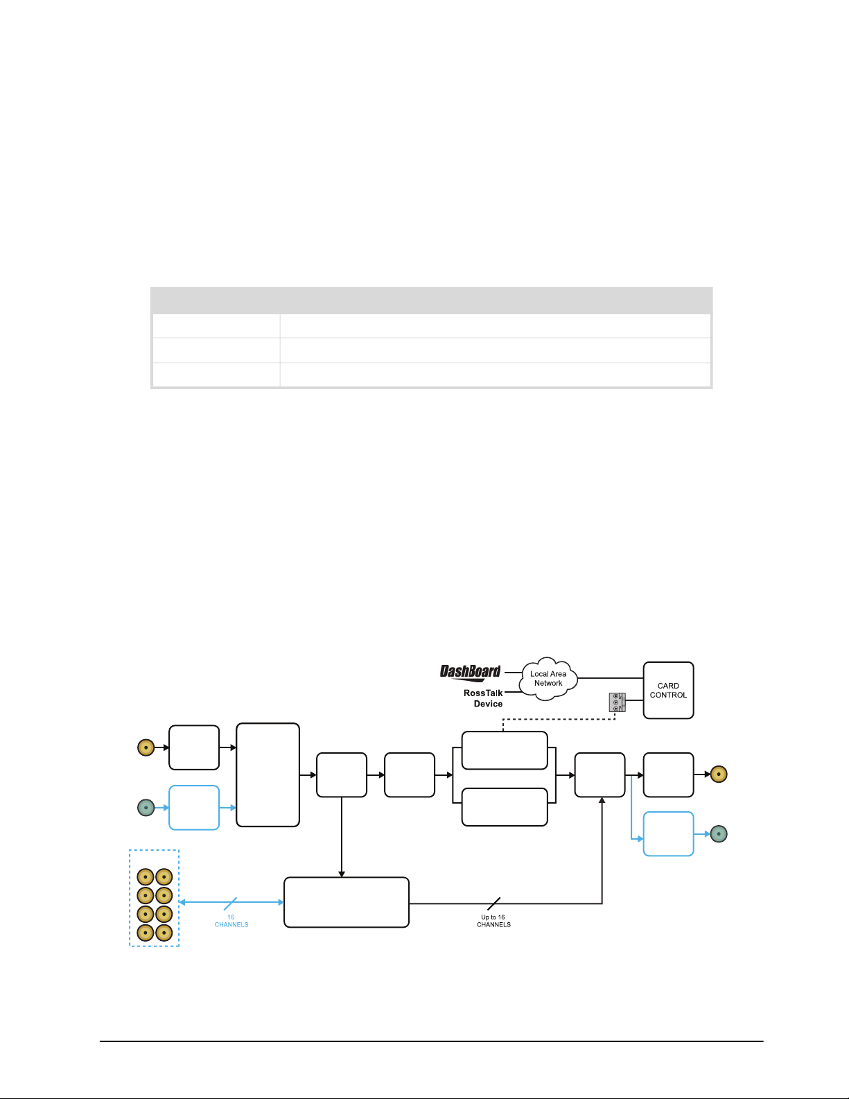
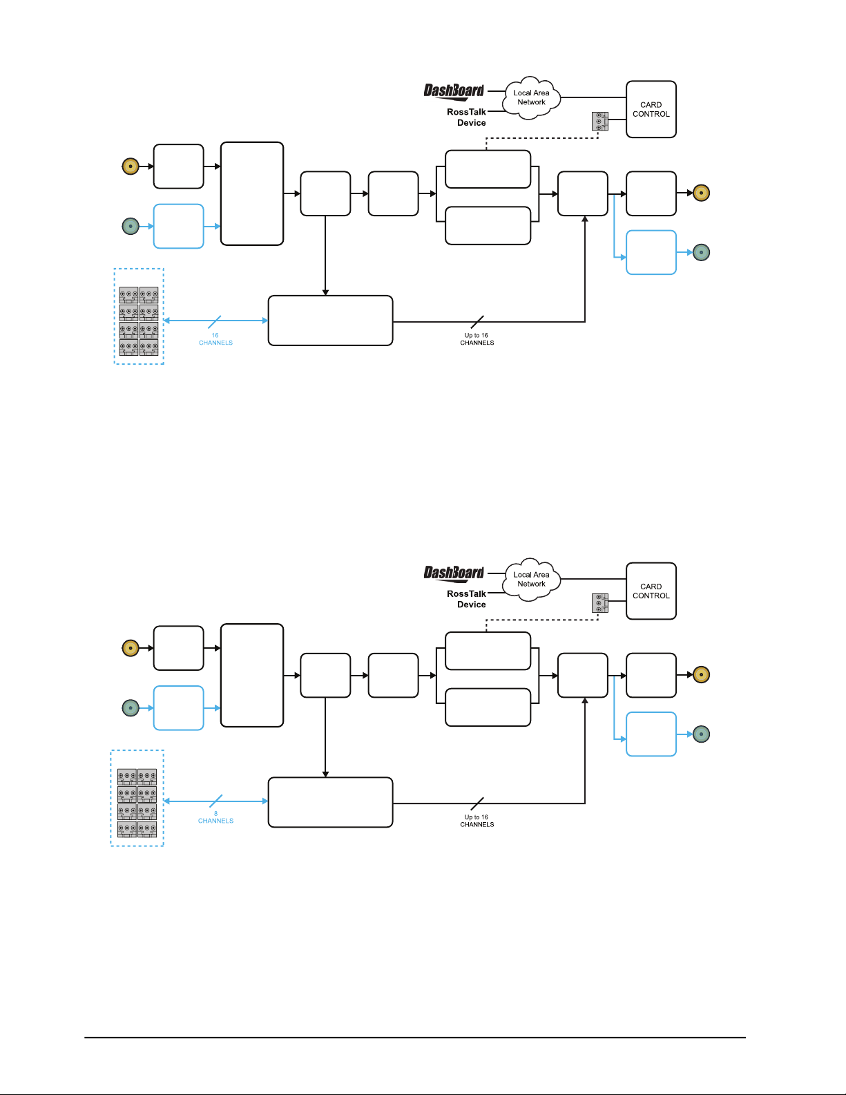
The AMX-8952-A (Figure 1) and AMX-8952-B (Figure 2) are capable of embedding or de-embedding
up to eight AES/EBU pairs (16 audio channels) into one HD/3G/12G-SDI signal. Audio proc control on
each input allows for audio processing with independent channel Sample Rate Conversion (SRC),
gain of +/-20dB, audio delay up to 1 second and channel phase invert and summing capability. If the
input is a synchronous 48kHz signal, the audio can be embedded into the SDI signal unaltered. If
the input is not a synchronous 48kHz signal, it may be converted using SRC before it is embedded
on the SDI output.
a
The AMX-8952-A offers eight 75ohm unbalanced AES connections while the AMX-8952-B offers
eight 110ohm balanced AES connections.
GPIO
(1,2)
SDI IN
(BNC 1)
SDI
BI-DIR
(BNC 3)
AES BI-DIR*
*The input is for embedding discrete audio into the SDI signal.
The output is for monitoring/feeding to external devices
SDI RX
SDI RX
INPUT
SELECT /
SWITCHOVER
AUDIO
DMX
AUDIO PROC
SRC, GAIN, DELAY,
CROSSPOINT
ANC RX
Figure 1 AMX-8952-A — Simplified Block Diagram
BYPASS
*Uses active SDI input.
FRAME SYNC /
VIDEO DELAY
ANC TX
AUDIO
ENCODE
SDI TX
SDI TX
SDI OUT
(BNC 2)
SDI
BI-DIR
(BNC 3)
AMX-8952 Series User Guide (v5.0) Before You Begin • 13
Page 14
GPIO
(1,2)
SDI IN
(BNC 1)
SDI
BI-DIR
(BNC 3)
AES BI-DIR*
*The input is for embedding discrete audio into the SDI signal.
The output is for monitoring/feeding to external devices
SDI RX
SDI RX
INPUT
SELECT /
SWITCHOVER
AUDIO
DMX
AUDIO PROC
SRC, GAIN, DELAY,
CROSSPOINT
ANC RX
BYPASS
*Uses active SDI input.
FRAME SYNC /
VIDEO DELAY
ANC TX
AUDIO
ENCODE
SDI TX
SDI TX
Figure 2 AMX-8952-B — Simplified Block Diagram
AMX-8952-C Overview
The AMX-8952-C includes one multi-rate SDI input which supports up to 16 channels of embedded
audio and 4 (pairs) of analog audio I/O. (Figure 3) The AMX-8952-C is capable of embedding or
de-embedding up to four analog audio pairs into an HD/3G/12G-SDI signal. Audio proc controls on
each input allows for gain control of +/- 10dB, audio delay up to 1 second, and channel phase invert
and summing capability.
SDI OUT
(BNC 2)
SDI
BI-DIR
(BNC 3)
SDI IN
(BNC 1)
SDI
BI-DIR
(BNC 3)
ANLG BI-DIR*
*The input is for embedding discrete audio into the SDI signal.
The output is for monitoring/feeding to external devices
SDI RX
SDI RX
INPUT
SELECT /
SWITCHOVER
BYPASS
AUDIO
DMX
AUDIO PROC
SRC, GAIN, DELAY,
CROSSPOINT
ANC RX
*Uses active SDI input.
FRAME SYNC /
VIDEO DELAY
Figure 3 AMX-8952-C — Simplified Block Diagram
GPIO
(1,2)
ANC TX
AUDIO
ENCODE
SDI TX
SDI TX
SDI OUT
(BNC 2)
SDI
BI-DIR
(BNC 3)
14 • Before You Begin AMX-8952 Series User Guide (v5.0)
Page 15

Features
The following features are standard for the AMX-8952 series:
• Supports embedding of non-PCM data such as Dolby® Digital and Dolby® E
• Two SDI processed outputs
• Audio embedding for all popular formats
• Full control over channel assignments, primary and backup sources
• Audio proc controls such as gain, invert, delay, and sum
• Internally generated test patterns and test tones
• Programmable video output on SDI input loss
• Automatic input video format detection
• Backup audio insertion on audio input loss
• Programmable silence detection and timeout thresholds
• Ability to strip VANC data from specific or all lines of a video output
• Reports status and configuration remotely via the DashBoard Control System
• Fits openGear frames
• 5-year transferable warranty
User Interfaces
The AMX-8952 includes two interfaces for control and monitoring for your card.
DashBoard Control System
The DashBoard Control System enables you to monitor and control openGear frames and cards
from a computer. DashBoard communicates with other cards in the openGear frame through the
Network Controller Card. The DashBoard Control System software and manual are available for
download from our website.
For More Information on...
• on the AMX-8952 menus in DashBoard, refer to “DashBoard Menus”.
• on using DashBoard, refer to the DashBoard User Manual available from our website.
SNMP Monitoring and Control
The Network Controller Card in the openGear frame can provide optional support for remote
monitoring of your frame and using Simple Network Management Protocol (SNMP), which is
compatible with many third-party monitoring and control tools.
For More Information on...
• on enabling SNMP Monitoring and Control for your frame, refer to the MFC-8300 Series User
Manual.
• on SNMP controls for the AMX-8952, refer to your AMX-8952 Management Information Base
(MIB).
AMX-8952 Series User Guide (v5.0) Before You Begin • 15
Page 16

16 • Before You Begin AMX-8952 Series User Guide (v5.0)
Page 17
Hardware Overview
This chapter presents information on the AMX-8952 hardware components and features.
Marketing Codes Overview
The AMX-8952 is an openGear modular system composed of two sub-systems.
• a main PCB which connects to a rear module and the openGear frame midplane
• a rear module that provides physical connectors
Table 2 outlines which rear module mates with specific main PCB version and openGear frames.
Table 2 Rear Modules — Supported openGear Frames
Main PCB
Marketing Code
AMX-8952-A 8952AR-001A R3A-8952 8322AR-329 OG3-FR, OGX-FR
AMX-8952-B 8952AR-001B R3B-8952 8322AR-330 OG3-FR, OGX-FR
AMX-8952-C 8952AR-002A R3C-8952 8322AR-330 OG3-FR, OGX-FR
PCB Part
Number
Marketing Code
Rear Module
Rear Module
Part Number
Supported
openGear Frame
Notice — Installing the AMX-8952 in a frame other than the OG3-FR or OGX-FR could damage the
card, the rear module, or both.
Main PCB Overview
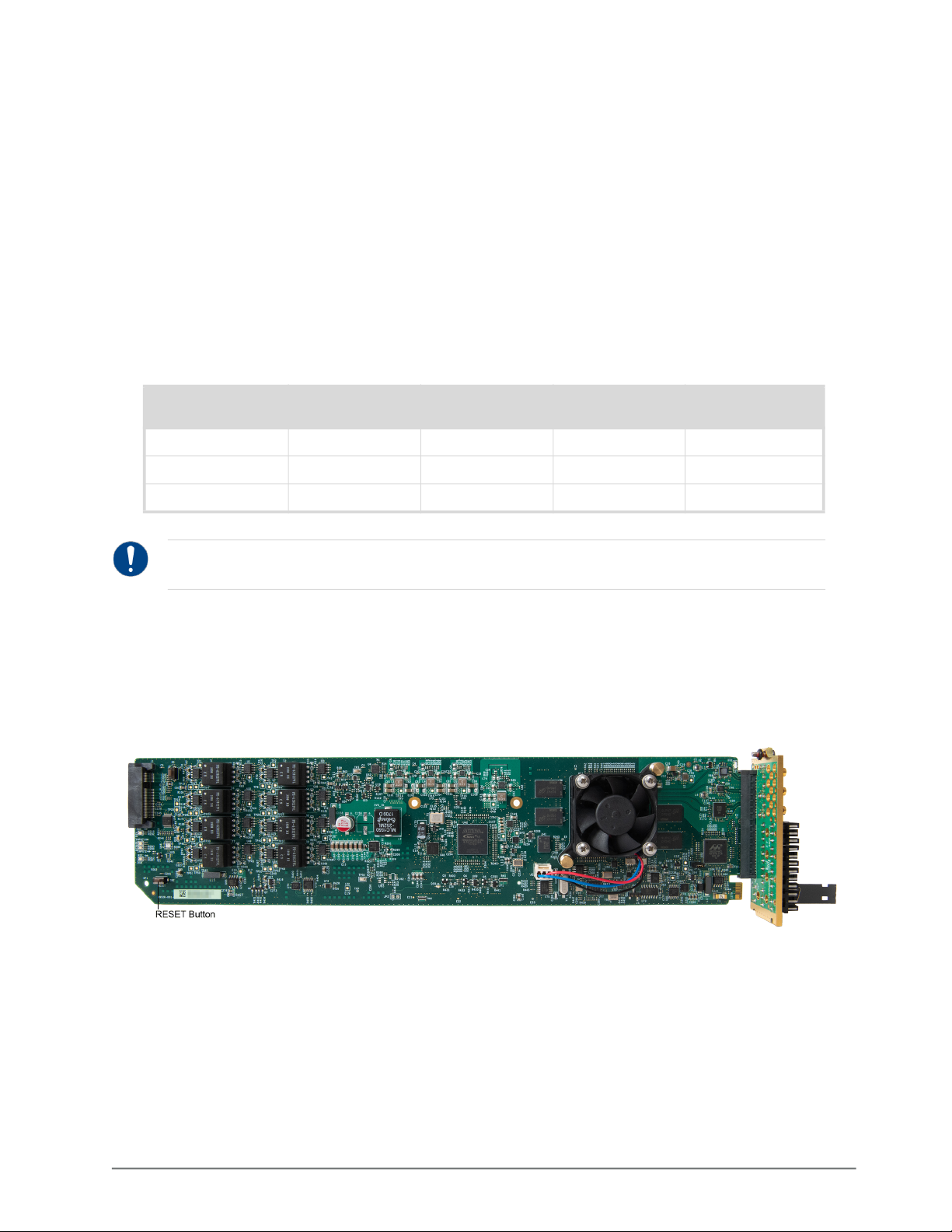
The main PCB is a typical openGear card. An ejector on one end secures the module to the slot
inside the openGear frame, and the other end inserts into a connector on the back of the rear
module.
Figure 4 AMX-8952 — Base Card Components
RESET Button
Pressing this button resets the microprocessor and re-initializes the card. This is a hard reset of the
card. This action should only be before as advised by Ross Video Technical Support.
AMX-8952 Series User Guide (v5.0) Hardware Overview • 17
Page 18
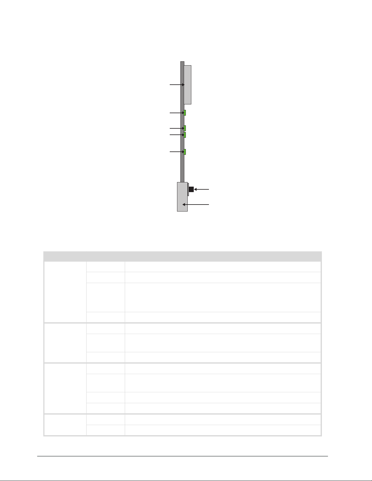
Monitoring via the Card-edge
The front-edge of the main PCB has LED indicators for indicating alarms, and communication
activity. (Figure 5)
REF Jumper (J1)
PWR
INPUT 1
INPUT 2
REF
Reset Button
Card Ejector
Figure 5 Card-edge Features
Table 3 provides information on the LED displays.
Table 3 AMX-8952 LED Descriptions
LED Color Description
PWR Green The card is powered on and is operating correctly
Flashing The card software is updating
Red When lit red, this LED indicates:
• the card is booting, or
• a major alarm condition is occurring on the card
Off The card is not powered on
INPUT 1 Green A valid SDI input signal is detected on the SDI IN BNC
Flashing
Green/Red
A valid SDI input signal is detected on the SDI IN BNC, but the card
is not locked to a reference signal
Red The SDI input signal connected to the SDI IN BNC is not valid
INPUT 2 Green A valid SDI input signal is detected on the SDI BI-DIR BNC
Flashing
Green/Red
A valid SDI input signal is detected on the SDI BI-DIR BNC, but the
card is not locked to a reference signal
Red The SDI input signal connected to the SDI BI-DIR BNC is not valid
Off The SDI BI-DIR BNC is configured as an output in DashBoard
REF Green A valid reference signal is detected on the REF IN BNC
Red An unsupported reference signal is detected on the REF IN BNC
18 • Hardware Overview AMX-8952 Series User Guide (v5.0)
Page 19
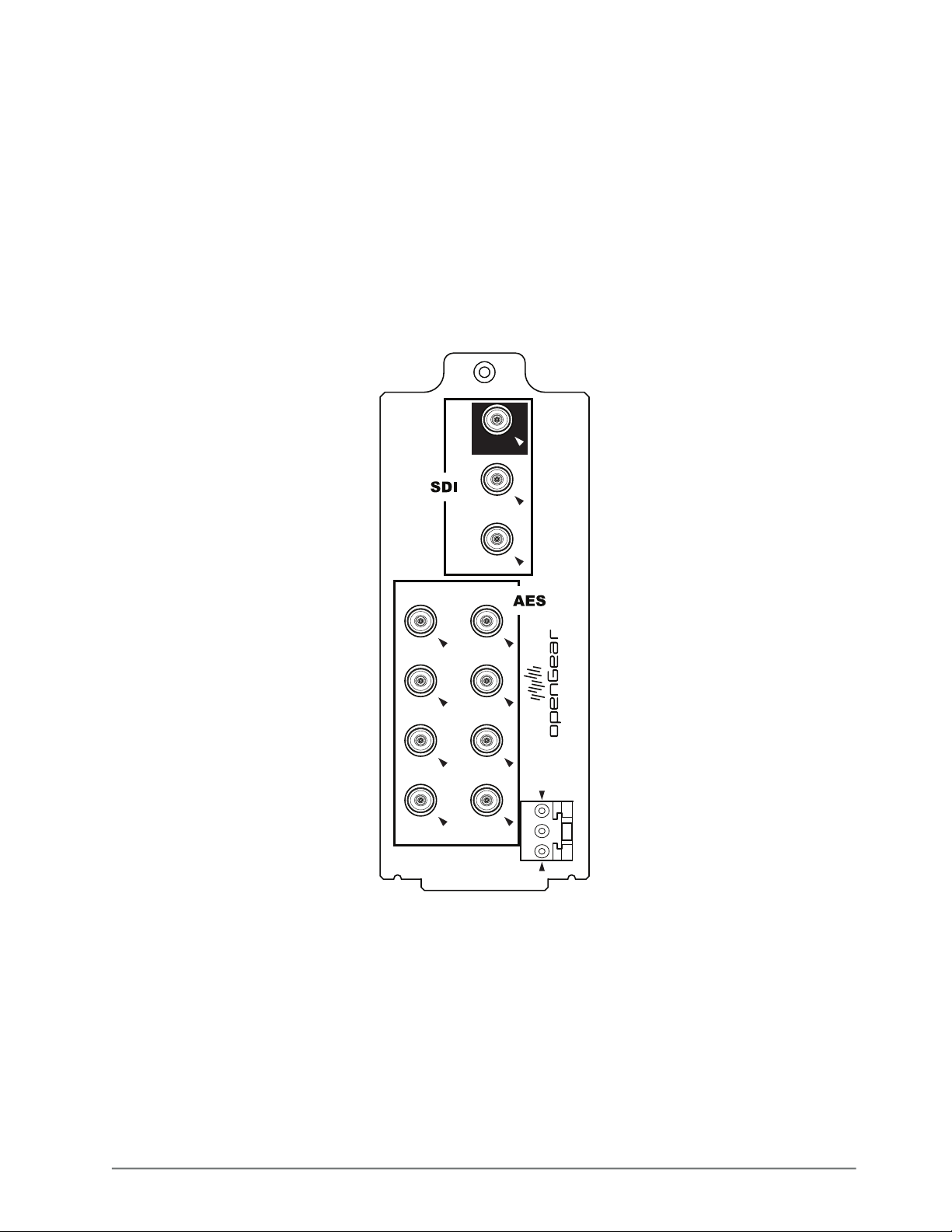
Supported Rear Modules
This section summarizes the connections and cabling designations for each AMX-8952 series card.
Each rear module occupies two slots in the openGear frame and accommodates one card.
AMX-8952-A
The AMX-8952-A includes the following connections:
• 1 SDI input BNC
• 1 SDI output BNC
• 1 bi-directional SDI BNC
• 8 AES unbalanced connections on BNCs
• 2 GPIO connections
BP
1
SDI IN
2
SDI OUT
3
SDI BI-DIR
1
AES 1
3
AES 3
5
AES 5
7
AES 7
AES 2
AES 4
AES 6
AES 8
2
4
AMX-8952-A
6
GPIO 1
8
GPIO 2
Figure 6 Cabling Designations — AMX-8952-A
AMX-8952 Series User Guide (v5.0) Hardware Overview • 19
Page 20
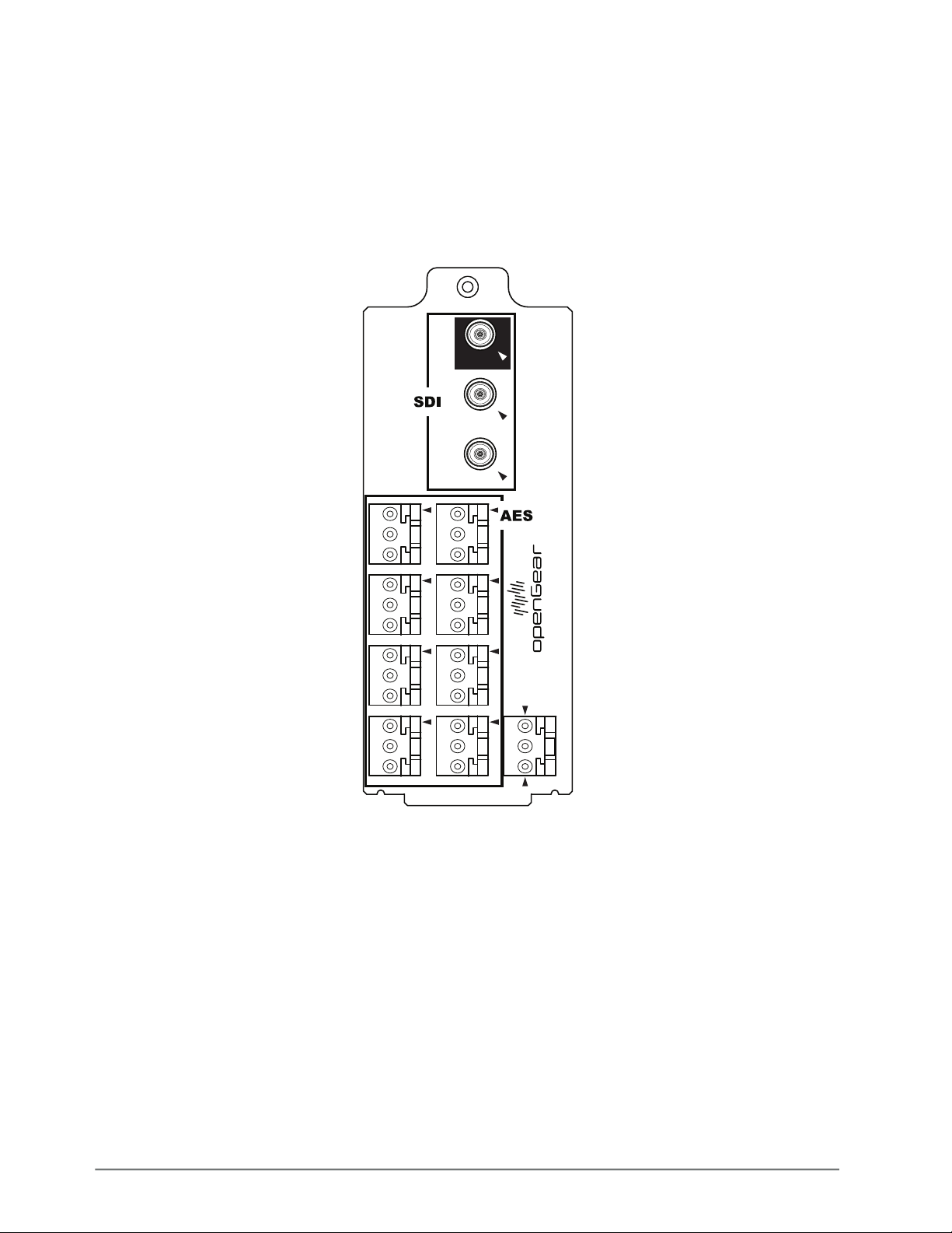
AMX-8952-B
The AMX-8952-B includes the following connections:
• 1 SDI input BNC
• 1 SDI output BNC
• 1 bi-directional SDI BNC
• 8 embedded audio balanced connections on 3-pin connectors
• 2 GPIO connections
BQ
1
SDI IN
2
SDI OUT
3
SDI BI-DIR
1
3
5
7
2
4
AMX-8952-B
6
GPIO 1
8
GPIO 2
Figure 7 Cabling Designations — AMX-8952-B
20 • Hardware Overview AMX-8952 Series User Guide (v5.0)
Page 21
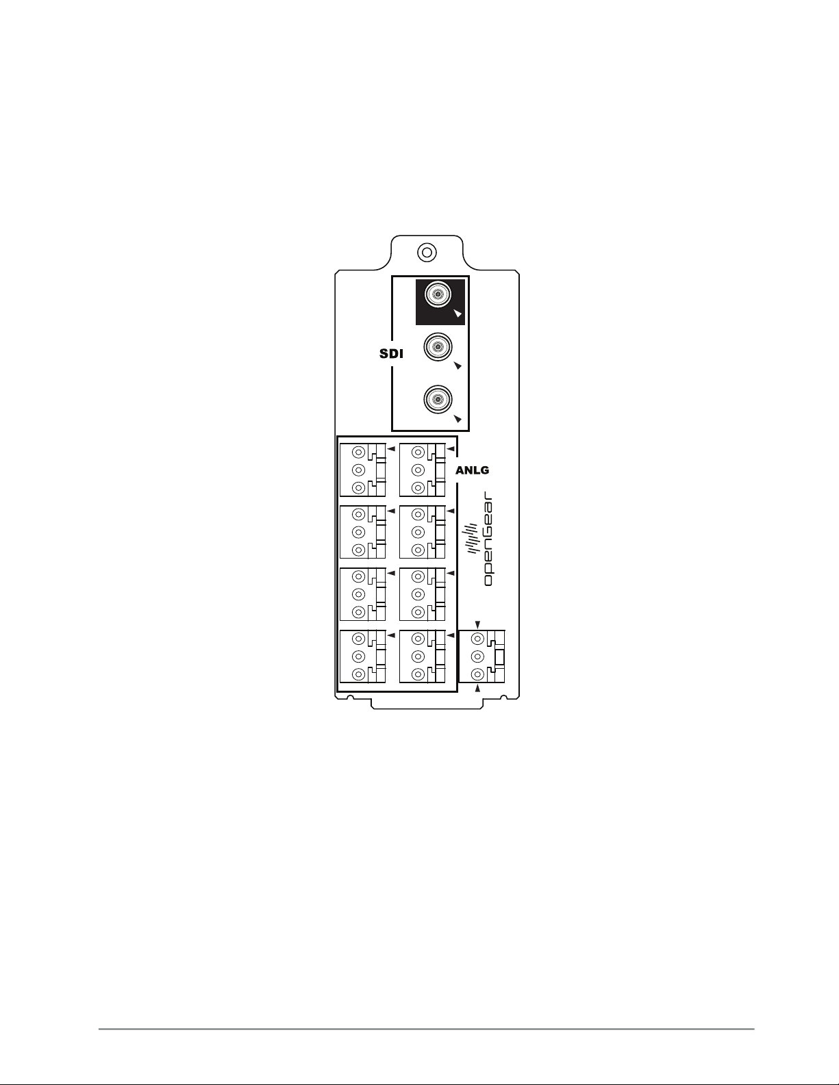
AMX-8952-C
The AMX-8952-C includes the following connections:
• 1 SDI input BNC
• 1 SDI output BNC
• 1 bi-directional SDI BNC
• 8 analog balanced analog connections on 3-pin connectors
• 2 GPIO connections
BQ
1
SDI IN
2
SDI OUT
3
SDI BI-DIR
1A
2A
3A
4A
1B
2B
3B
4B
AMX-8952-C
GPIO 1
GPIO 2
Figure 8 Cabling Designations — AMX-8952-C
AMX-8952 Series User Guide (v5.0) Hardware Overview • 21
Page 22

22 • Hardware Overview AMX-8952 Series User Guide (v5.0)
Page 23

Physical Installation
Installing an AMX-8952 series card into the openGear frame requires you to remove the blank
plates in the designation frame slots, install the required rear module into the frame rear panel,
and then install the AMX-8952 series card into the required frame slot.
If you have questions pertaining to the installation of your card, contact us at the numbers listed in
the section “Contacting Technical Support”. Our technical staff is always available for
consultation, training, or service.
The AMX-8952 series requires the MFC-OG3-N Network Controller card to be installed in the
openGear frame. The MFC-8322-S does not support the AMX-8952 series cards.
Before You Begin
These installation guidelines assume the following:
• Ensure the openGear frame frame is properly installed. Refer to the User Guide for your frame.
• A valid IP addresses is available for the AMX-8952.
• If the rear module is already installed in the openGear frame, proceed to “Installing the
AMX-8952 Card into an openGear Frame”.
Static Discharge
Throughout this chapter, please heed the following cautionary note:
ESD Susceptibility — Static discharge can cause serious damage to sensitive semiconductor
devices. Avoid handling circuit boards in high static environments such as carpeted areas and when
synthetic fiber clothing is worn. Always exercise proper grounding precautions when working on circuit
boards and related equipment.
Removing the Blank Plates from the Rear Panel
When a frame slot is not populated with an openGear card, a blank plate must be installed to
ensure proper frame cooling and ventilation.
Notice — Installing the rear modules in a frame other than an OG3-FR or OGX-FR series frame could
damage the card, the rear module, or both.
To remove a blank plate from the openGear frame
1. Locate the slots in the openGear frame you wish to install the AMX-8952 into. It is
recommended to use the following slot combinations:
• Slots 1, 2 • Slots 7, 8 • Slots 13, 14 • Slots 19, 20
• Slots 3, 4 • Slots 9, 10 • Slots 15, 16
• Slots 5, 6 • Slots 11, 12 • Slots 17, 18
2. Use a Phillips screwdriver to unfasten each blank plate from the openGear frame backplane.
3. Remove each blank plate from the chassis and set aside.
AMX-8952 Series User Guide (v5.0) Physical Installation • 23
Page 24

Installing the Rear Module into the openGear Frame
If the rear module is already installed in the openGear frame, proceed to the section “Installing the
AMX-8952 Card into an openGear Frame”.
To install a rear module into the openGear frame
1. For each retaining screw on the rear module, push the o-ring to the end of the screw (but not
off the screw). This will help to align the rear module to the frame backplane in step 3.
2. Seat the bottom of the rear module in the seating slots at the base of the openGear frame’s
backplane.
3. Align the top holes of the rear module with the screw holes on the top-edge of the frame
backplane.
4. Using a Phillips screwdriver and the provided screw, fasten the rear module to the backplane.
Do not fully tighten the screws until after installing the card and you have verified that the
AMX-8952 card aligns with the rear module.
Installing the AMX-8952 Card into an openGear Frame
The slot that the AMX-8952 installs into depends on the slot combination you installed the rear
module in. This allows adequate spacing to avoid damaging the card, the cards installed in the
neighboring slots, or both.
To install the AMX-8952 into the openGear frame
1. Locate the slot the AMX-8952 card will slide into. Refer to Table 4 for valid slot combinations.
Table 4 Card Slot Combinations
Rear Module is Installed in Card Installs into Slot
Slots 1, 2 1
Slots 3, 4 3
Slots 5, 6 5
Slots 7, 8 7
Slots 9, 10 9
Slots 11, 12 11
Slots 13, 14 13
Slots 15, 16 15
Slots 17, 18 17
Slots 19, 20 19
2. Verify that the AMX-8952 card aligns with the rear module.
3. Using a Phillips screwdriver fasten the rear module to the backplane using the provided screws.
Do not over tighten the screws.
4. Hold the card by the edges and carefully align the card edges with the slot rails in the frame.
5. Fully insert the card into the frame until the card is properly seated in the rear module.
24 • Physical Installation AMX-8952 Series User Guide (v5.0)
Page 25

Cabling the Ethernet Port on the openGear Frame
You must provide an Ethernet connection to the openGear frame that houses the AMX-8952.
The AMX-8952 is connected to your network via the MFC-OG3-N in the openGear frame. This
enables the AMX-8952 to interface with other cards in the frame, and the computer running the
DashBoard client. After a physical connection is established, DashBoard is used to configure the
network settings for the AMX-8952.
Contact your IT department before connecting to your facility network to ensure that there are no
conflicts. They will provide you with an appropriate value for the IP Address, Subnet Mask, and
Gateway for your AMX-8952.
Contact your network administrator if problems are experienced when connecting to a network
hub.
For More Information on...
• cabling the Ethernet port on the openGear frame, refer to the user guide for your frame.
• configuring the Ethernet port on the openGear frame, refer to the user guide for your frame.
Reference Cabling
This section provide information on cabling the reference signal for your card.
To cable the reference source for your card
1. If you wish to use the frame reference input, connect the reference input to the
input on the openGear frame.
2. If you wish to use a local reference input, connect the reference input source to the
connector on your rear module.
REF1 or REF2
SDI IN
Video Cabling
Each rear module provides one SDI input, one SDI output, and one SDI bi-directional connection.
Loss of Input Failover Mode
Refer to “Enabling the Loss of Input Failover Mode” for details.
Audio Cabling
The 8322AR-329 rear module provides eight unbalanced audio connections for AES sources via
HD-BNC ports. Connect your destination devices to the AUDIO ports on the 8322AR-329 rear
module as required.
The 8322AR-330 rear module provides eight balanced audio connections on 3-pin connectors. This
rear module is required for the AMX-8952-B and AMX-8952-C. Cable your rear module using the
following procedure.
AMX-8952 Series User Guide (v5.0) Physical Installation • 25
Page 26
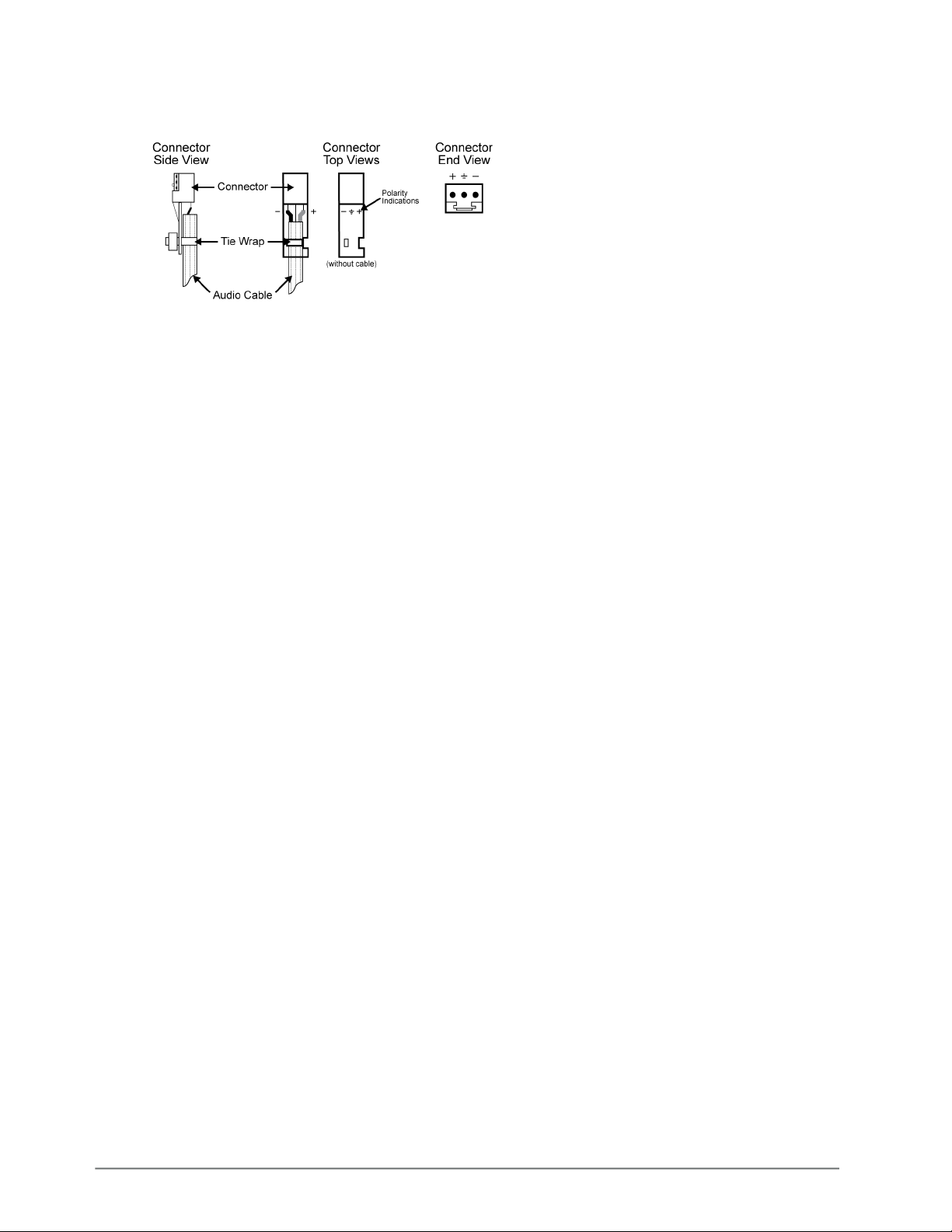
To wire the audio for the 8322AR-330
1. Insert an audio wire to the designated polarity slot on the connector of the rear module.
2. Use a tweaker screwdriver to tighten the corresponding capture screw.
3. Repeat steps 1 and 2 for each wire on each connector.
4. Once the cables are wired to the connectors, install the connectors on the terminal blocks for
the rear module.
26 • Physical Installation AMX-8952 Series User Guide (v5.0)
Page 27

Getting Started
This chapter provides instructions for launching DashBoard, and accessing the AMX-8952 interfaces
in DashBoard.
If you have questions pertaining to the operation of AMX-8952, contact us at the numbers listed in
the section “Contacting Technical Support”. Our technical staff is always available for
consultation, training, or service.
Before You Begin
Ensure that:
• An MFC-OG3-N or MFC-OGX-N Network Controller Card is installed in your openGear frame.
• The openGear frame that houses the AMX-8952 displays in the Basic Tree View of DashBoard.
• The AMX-8952 displays as a sub-node in the openGear frame tree.
• Your facility IT Department provided the required network settings to be assigned to the
AMX-8952.
Launching DashBoard
DashBoard must run on a computer that has a physical wired Ethernet connection. Wireless
connections do not allow device discovery.
For More Information on...
• downloading and installing the DashBoard client software, refer to the DashBoard User Manual.
• the AMX-8952 interfaces in DashBoard, refer to the chapter “DashBoard Menus”.
To launch DashBoard
1. Ensure that you are running DashBoard software version 9.2.0 or higher.
2. Launch DashBoard by double-clicking its icon on your computer desktop.
Accessing the AMX-8952 Interfaces in DashBoard
The interfaces are accessed by double-clicking the AMX-8952 node in the DashBoard Tree View.
To access the AMX-8952 interfaces in DashBoard
1. Launch DashBoard.
2. In the Basic Tree View of DashBoard, locate the openGear frame the AMX-8952 is installed in.
3. Expand the openGear frame node to display a list of sub-nodes that represent an openGear
card installed in a specific frame slot.
4. Locate the AMX-8952 node in the openGear frame tree.
5. Expand the AMX-8952 node to display a list of sub-nodes for the card.
The first sub-node provides access to the Global settings for the card. The second sub-node
provides an interface for configuring the inputs and outputs of the AMX-8952.
6. Double-click the Global sub-node to display that interface in the right pane of the DashBoard
window.
The Signal and Setup tabs are automatically selected in the left and right panes respectively.
AMX-8952 Series User Guide (v5.0) Getting Started • 27
Page 28
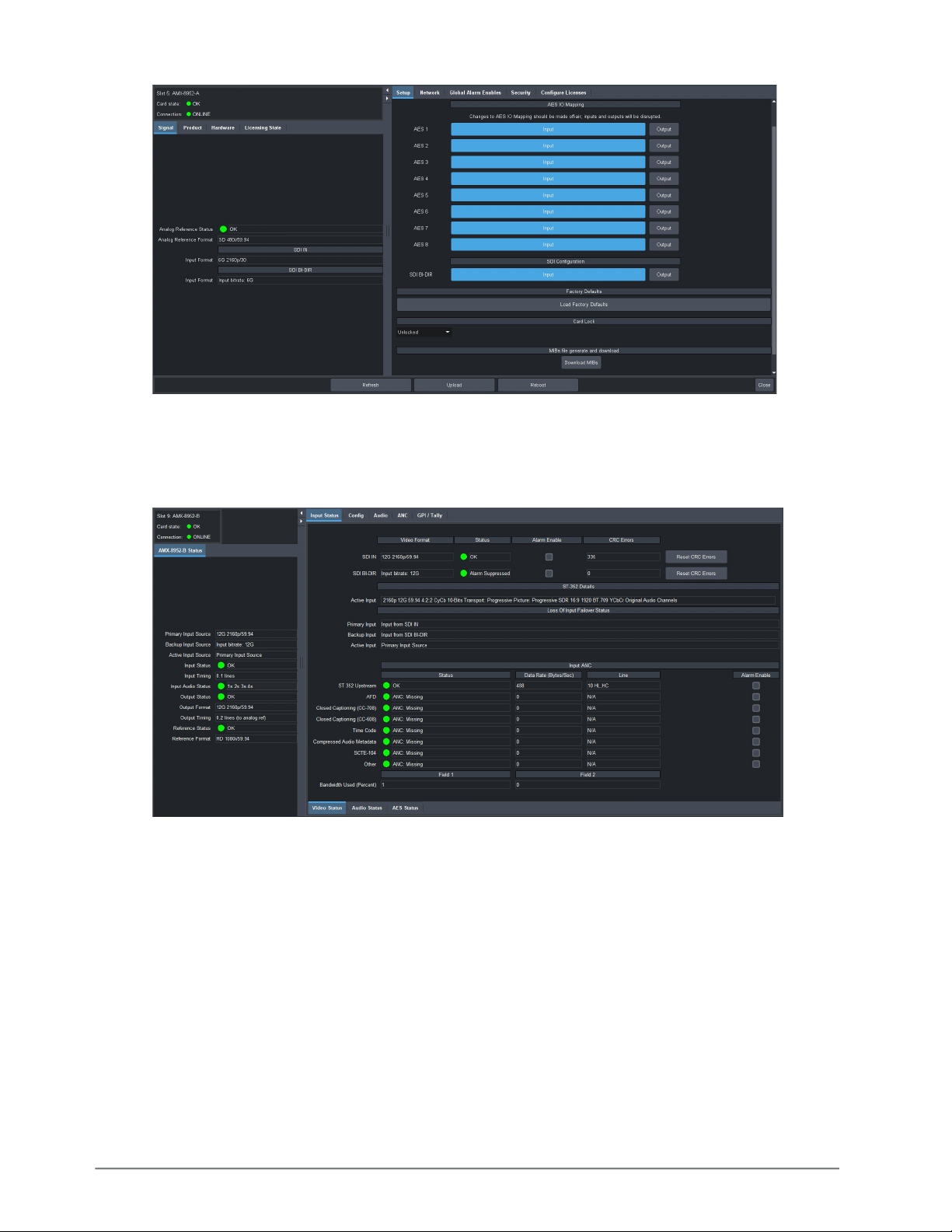
7. Double-click the AMX-8952 sub-node to display the interface for that feature in the right pane
of the DashBoard window.
The AMX-8952 Status and Input Status tabs are automatically selected in the left and right
panes respectively.
28 • Getting Started AMX-8952 Series User Guide (v5.0)
Page 29

Configuring the Network Settings
This chapter outlines how to update the network settings assigned to the AMX-8952.
If difficulties or problems are experienced when assigning IP addresses, contact your network
administrator.
Before You Begin
Ensure that:
• The OGX-FR frame that houses the AMX-8952 displays in the Basic Tree View of DashBoard
• The AMX-8952 displays as a sub-node in the OGX-FR frame tree
• Your facility IT Department has provided you with the settings to be assigned to the AMX-8952
Changing the Network Settings of the AMX-8952
Once you have establish connection to the card, you may want to change the IP Address from the
default setting to one that was provided by your IT Department.
Ross Video recommends using a static IP Address.
To change the network settings for the AMX-8952
1. Display the Global interface as outlined in “To access the AMX-8952 interfaces in DashBoard”.
2. Select the Network tab.
3. If you are manually configuring the Ethernet settings for the AMX-8952:
a. Use the Mode menu to select Static.
b. Use the Static IP Address field to specify the new static IP Address for the AMX-8952. This is
the address the card will use within the openGear frame.
c. Use the Subnet field to specify the subnet mask for your network.
d. Use the Static Gateway field to specify the gateway for communications outside of the local
area network (LAN) the card will use.
4. If you want the network settings to be automatically obtained, select DHCP from the Mode
menu.
5. Click Apply to save the new settings.
The AMX-8952 card reboots automatically.
AMX-8952 Series User Guide (v5.0) Configuring the Network Settings • 29
Page 30

30 • Configuring the Network Settings AMX-8952 Series User Guide (v5.0)
Page 31
Licensed Features
The AMX-8952 has software licenses for enabling functions and features of the card. This chapter
outlines the available software licensed features, and how to install a software key for a licensed
feature.
License Keys Overview
Table 5 provides a brief summary on the types of licensed features available for the AMX-8952.
Table 5 List of AMX-8952 Licensed Features
License Description
AMX-8952-FS-LICENSE Frame sync license
AMX-8952-UHD-LICENSE UHD license
Installing a License Key
Ross Video uses license keys to control user access to specific AMX-8952 features. You can obtain a
key for a AMX-8952 licensed feature from Ross Video Technical Support.
To install a license key
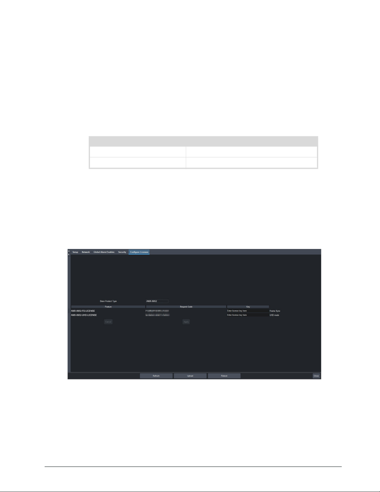
1. Display the Global interface as outlined in “To access the AMX-8952 interfaces in DashBoard”.
2. Select the Configure Licenses tab.
3. Make a note of the character string in the Request Code field for the feature you wish to
enable.
4. Contact Ross Video using the information found in the section “Contacting Technical
Support”.
a. When you speak to your Technical Support representative, tell them your name, your facility
name, and the Request Code from the Configure Licenses tab.
b. You will be given a License Key that must be entered in the applicable field in the Licenses
table.
AMX-8952 Series User Guide (v5.0) Licensed Features • 31
Page 32

5. Enter the provided License Key in the applicable Key field in the Configure Licenses tab.
6. Click Apply in the row for the License Key you entered in step 5.
Removing a License Key
Disabling a License Key removes user access to the AMX-8952 features associated with that License
Key.
To re-enable the features, you will need to contact Ross Technical Support and request a new
License Key.
To remove a AMX-8952 license key
1. Display the Global interface as outlined in “To access the AMX-8952 interfaces in DashBoard”.
2. Select the Configure Licenses tab.
3. Click in the Key field for the licensed feature you want to remove.
4. Type
5. Click Apply to remove the license.
remove.
32 • Licensed Features AMX-8952 Series User Guide (v5.0)
Page 33

Reference Setup
The procedures in this chapter assume that the AMX-8952 interface displays in the right-pane of the
DashBoard window.
Frame Rate Compatibility
The card supports a number of reference modes for both internal and external reference signals.
The card allows you to use any interlaced video format to operate the card in any format of the
same frequency; however, the use of 480i or 576i (Composite Sync) reference signals for High
Definition (720p, 1080i, or 1080p) video modes is not recommended.
When using a progressive format reference signal to lock an interlaced format video signal, the
lock will be Frame Locked but Field indeterminate.
Table 6 outlines the AMX-8952 frame rate compatibility.
Table 6 Output/Reference Compatibility
Card Format Required Reference
HD-SDI Formats
720p 50Hz 576i
720p 50Hz
1080i 50Hz
720p 59.94Hz 480i
720p 59.94Hz
1080i 59.94Hz
1080i 50Hz 576i
1080i 50Hz
1080i 59.94Hz 480i
1080i 59.94Hz
1080pSF 23.98Hz 1080pSF 23.98Hz
1080pSF 24Hz 1080pSF 24Hz
1080p 23.98Hz 1080p 23.98Hz
1080p 24Hz 1080p 24Hz
1080p 25Hz 576i
1080i 50Hz
1080p 29.97Hz 480i
1080i 59.94Hz
1080p 30Hz 1080p 30Hz
1080p 50Hz 576i
1080i 50Hz
720p 50Hz
AMX-8952 Series User Guide (v5.0) Reference Setup • 33
Page 34

Table 6 Output/Reference Compatibility
Card Format Required Reference
1080p 59.94Hz 480i
720p 59.94Hz
1080i 59.94Hz
1080p 60Hz 720p 60Hz
1080i 60Hz
6G-SDI Formats
a
2160p 23.98Hz 1080p 23.98Hz
2160p 24Hz 1080p 24Hz
2160p 25Hz 576i
720p 50Hz
1080i 50Hz
2160p 29.97Hz 480i
1080i 59.94Hz
2160p 30Hz 1080p 30Hz
12G-SDI Formats
a
2160p 50Hz 576i
720p 50Hz
1080i 50Hz
2160p 59.94Hz 480i
720p 59.94Hz
1080i 59.94Hz
a.Requires the AMX-8952-UHD-LICENSE. Refer to
“Installing a License Key” for details.
Specifying a Global Analog Reference Source
The output video frame rate must match this reference frame rate.
To specify a global analog reference source for the AMX-8952
1. Display the Global interface as outlined in “To access the AMX-8952 interfaces in
DashBoard”.
2. Select the Setup tab.
3. Use the Reference Source options to specify the source for the reference input signal. Choose
from the following:
• Frame 1 — uses the source connected to the REF 1 port on the openGear frame.
• Frame 2 — uses the source connected to the REF 2 port on the openGear frame.
• Input SDI — uses the SDI IN signal (as defined in the Video Input area) as the reference
source.
34 • Reference Setup AMX-8952 Series User Guide (v5.0)
Page 35

Monitoring the Reference Signal via DashBoard
The status of the AMX-8952 may be monitored via its fields in the DashBoard client software or the
LEDs located on the front panel of the chassis.
To configure the reference alarm for the AMX-8952
1. Display the Global interface as outlined in “To access the AMX-8952 interfaces in DashBoard”.
2. Select the Global Alarm Enables tab.
3. Select the Reference Format box to enable the following fields to report when a reference is
not detected:
• Global > Card state (located in the top left corner of the Global interface)
• Global > Signal > Analog Reference Status
AMX-8952 Series User Guide (v5.0) Reference Setup • 35
Page 36

36 • Reference Setup AMX-8952 Series User Guide (v5.0)
Page 37
Video Configuration
This chapter outlines how to specify the output format and video source, and define the card
behavior during a loss of the input signal.
Configure the SDI BI-DIR Port
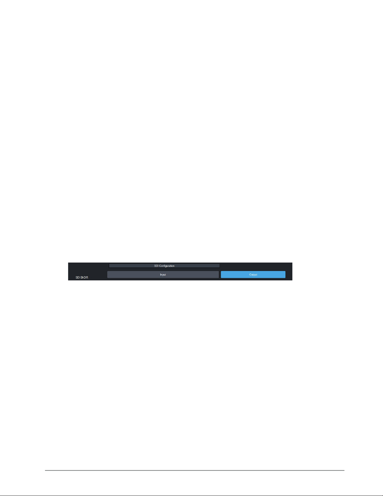
Each rear module includes a BNC that is an SDI bi-directional (BI-DIR) port. This provides the
opportunity to assign the port as an input or output depending on your system needs.
• When this port is assigned as an input, it can be used as a backup video source (see “To define
the primary SDI signal for the Loss of Input Failover mode”).
• When this port is assigned as an output, it can be used as a second SDI output for the card. In
output mode:
› The Input Status tab does not report the status of the SDI BI-DIR signal.
› The Loss of Input Failover feature is disabled.
› The Primary Video Source menu is locked to Input From SDI IN.
› The Backup Video Source menu is disabled and reports N/A.
› The switch between audio sources is ramped over 1 frame.
To assign a function to the SDI BI-DIR port
1. Display the Global interface as outlined in “To access the AMX-8952 interfaces in
DashBoard”.
2. Select the Setup tab.
3. Locate the SDI Configuration area of the tab.
4. Perform one of the following:
• Click Input to configure the SDI BI-DIR port as an input.
• Click Output to configure the SDI BI-DIR port as an output.
Specifying the Output Format and Video Source
You need to specify the video format for the card output and the source for the signal. Keep the
following in mind:
• If you select Matte or Test Pattern for the Video Output — The output will follow the format of the
last valid input signal. You can still override the format by selecting a different format from the
Output Format menu.
• If you select Video In for the Video Output and the Loss-of-Input is set to Matte/Test pattern —
Should the input fail, the output will be in the format of the last valid SDI input and displayed in
the Output Format menu. You cannot override the output format.
To specify the output format and video source for your card
1. Display the Global interface as outlined in “To access the AMX-8952 interfaces in DashBoard”.
2. Select the Config tab.
AMX-8952 Series User Guide (v5.0) Video Configuration • 37
Page 38
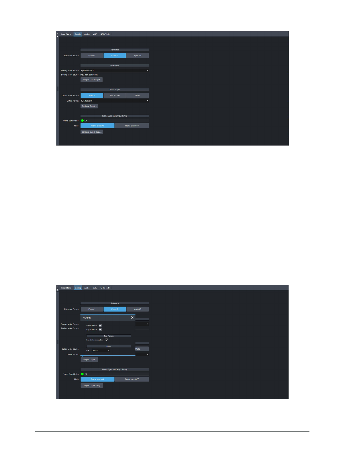
3. Locate the Video Output area of the tab.
4. Use the Output Video Source to specify the video signal the AMX-8952 will output. Choose
from the following:
• Video in — The output uses the active SDI input signal. Note that the Output Format menu is
now read-only. The output will apply the last valid video input video format.
• Test Pattern — A SMPTE bars test pattern will replace all of the output picture (but not the
HANC and VANC).
• Matte Pattern — A solid (single) color pattern will replace all of the output picture (but not
the HANC and VANC). Refer to “Specifying the Matte Color” to set the color for the matte
pattern.
5. If you chose Test Pattern or Matte Pattern in step 4, use the Output Format menu to select the
video format. Ensure that the output format is compatible with the selected reference format.
The Output Format setting overrides the Loss of Input video format.
6. Click Configure Output.
The Output dialog opens.
7. Enable the Clip White or Clip Black feature as outlined in Table 24.
8. Close the Output dialog.
38 • Video Configuration AMX-8952 Series User Guide (v5.0)
Page 39
Enabling the Loss of Input Failover Mode
By default, the AMX-8952 card provides a Loss of Input Failover feature where user can manually
switch from the primary SDI input signal to a secondary (backup) SDI input signal. The card stays on
the secondary SDI input signal until the user manually switches the card back to the primary signal.
On manual failover, the card will perform a clean/quiet switch if both SDI inputs are stable and
the same video format.
The user defines which SDI video signal (BNC 1 or BNC 3) is the primary and secondary using the
options in the AMX-8952 > Config tab. This tab also displays the button used to manually switch the
signals from primary to secondary (and vice versa).
To define the primary SDI signal for the Loss of Input Failover mode
1. Display the AMX-8952 interface as outlined in “To access the AMX-8952 interfaces in
DashBoard”.
2. Select the Config tab.
3. Locate the Video Input area of the tab.
4. Use the Primary Video Source menu to assign an SDI input signal as the primary signal for the
Loss of Input Failover mode. Choose from the following:
• Input from SDI IN — Assigns SDI IN (BNC 1) as the primary input signal when ACO is enabled.
• Input from SDI BI-DIR — Assigns SDI BI-DIR (BNC 3) as the primary input signal when ACO is
enabled.
You cannot assign the same SDI signal as the Primary Video Source and the Backup Video
Source.
To enable Failover mode and switch the SDI input signals
1. Display the AMX-8952 interface as outlined in “To access the AMX-8952 interfaces in
DashBoard”.
2. Select the Config tab.
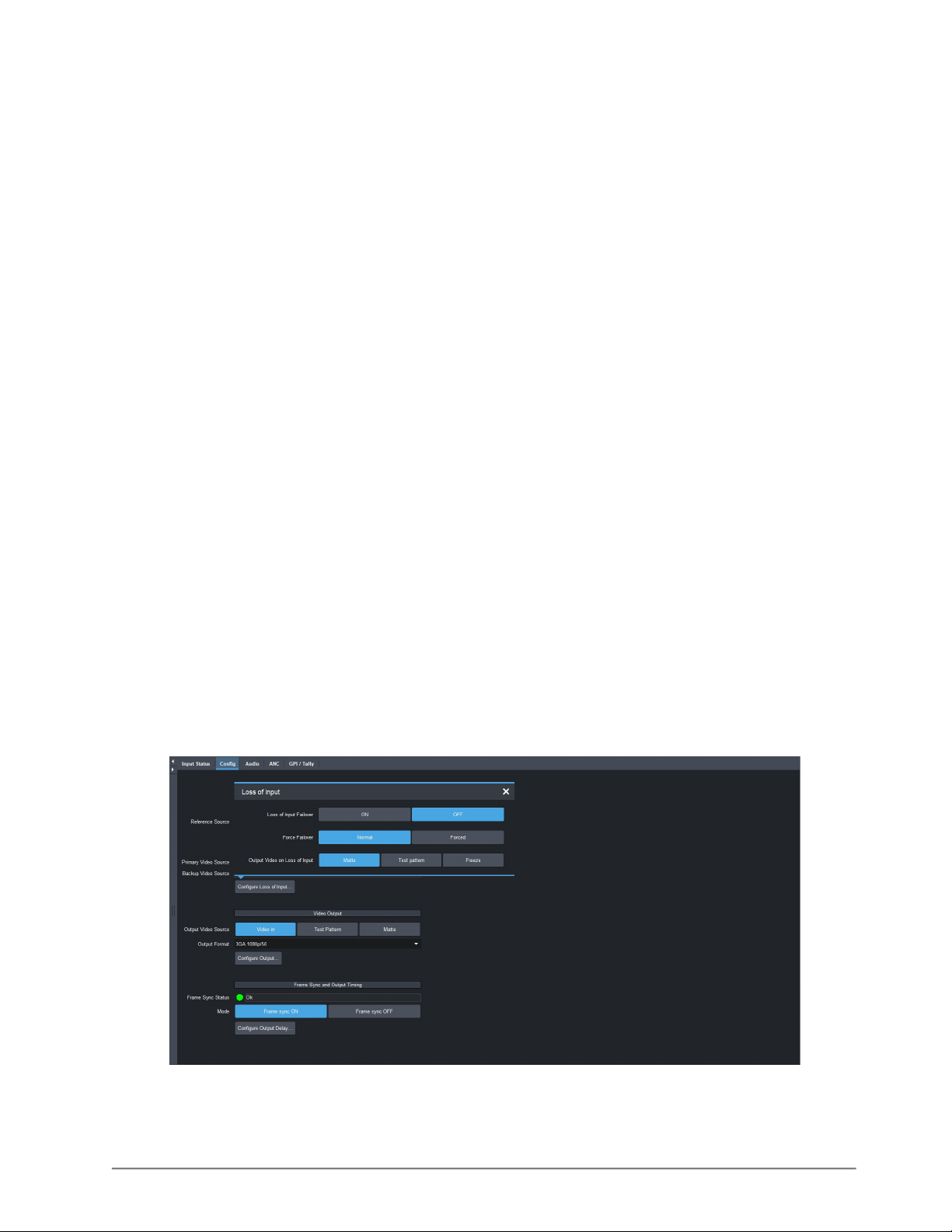
3. Click Configure Loss of Input.
The Loss of Input dialog opens.
4. In the Loss of Input Failover area, click ON.
The ON button automatically is lit (active) and the card switches from one signal to the other as
defined in “To define the primary SDI signal for the Loss of Input Failover mode”.
AMX-8952 Series User Guide (v5.0) Video Configuration • 39
Page 40
5. Use the Force Failover options to determine when the failover occurs. Choose from the
following:
When forcing a switchover, the AMX-8952 performs a clean/quiet switch between inputs if the
signals are both valid and the same format. The Frame Sync must be enabled to perform a clean
switch between mis-timed sources.
• Normal — When a loss of input occurs, the card automatically switches to the other video
source.
• Forced — The user manually switches to the other video source by clicking the Loss of Input
Failover buttons.
6. Close the Loss of Input dialog.
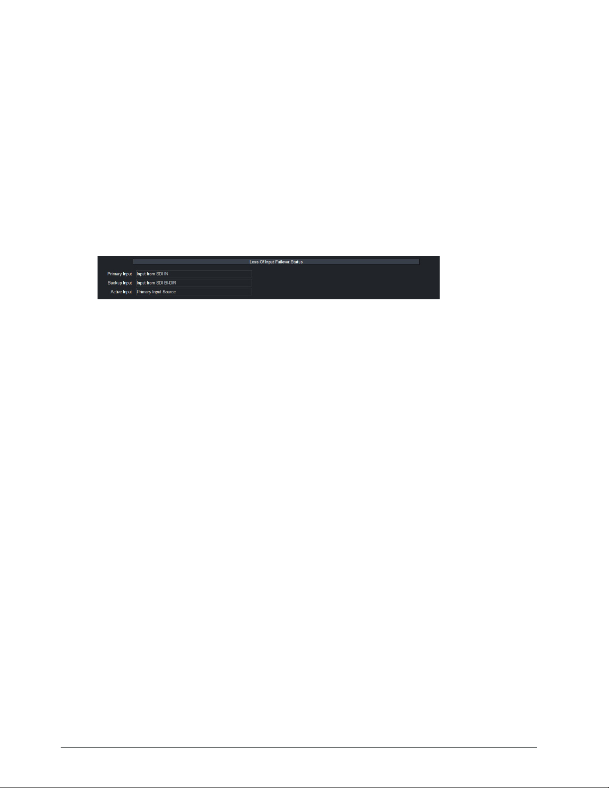
To verify the current active SDI input signal
1. Display the AMX-8952 > Input Status tab in DashBoard.
2. Locate the Loss of Input Failover Status area of the tab.
3. Use the Primary Input field to determine which SDI input signal is assigned as the Primary
Input Video Source.
4. Use the Backup Input field to determine which SDI input signal is assigned as the Backup Video
Source.
5. Use the Active Input field to determine which SDI input signal is currently active and in use.
Specifying the Output During a Loss of Input
The card enables you to specify the output during a loss of input, or during a change of input
format. The embedded audio will also go silent if passing from input to output (when another audio
source is not selected).
To specify the output if the video input is lost
1. Display the Config interface as outlined in “To access the AMX-8952 interfaces in
DashBoard”.
2. Click Configure Loss of Input.
The Loss of Input dialog opens.
3. Use the Output Video on Loss of Input menu to specify what to output when the card
experiences a loss of input. Choose from the following:
• Matte Pattern — A solid (single) color pattern will replace all of the output picture (but not
the HANC and VANC). Refer to “Specifying the Matte Color” to specify the color for the matte
pattern.
• Test Pattern — A SMPTE bars test pattern will replace all of the output picture (but not the
HANC and VANC).
• Freeze — Enables the card to freeze and output the last good frame of video before the loss
of input.
4. Close the Loss of Input dialog.
40 • Video Configuration AMX-8952 Series User Guide (v5.0)
Page 41
Specifying the Matte Color
Color selection is done by selecting a desired color from a list of options. The matte is a full raster
signal.
To specify the matte color
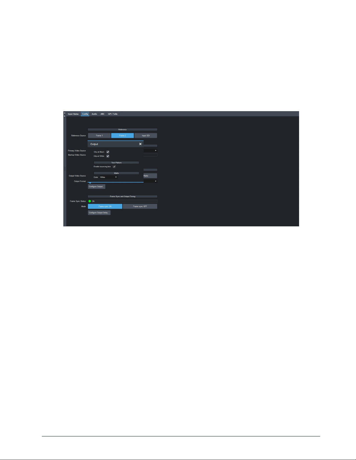
1. Display the Config interface as outlined in “To access the AMX-8952 interfaces in
DashBoard”.
2. Click Configure Output.
The Output dialog opens.
3. Use the Matte Color box to specify the color the Matte Pattern will display.
4. Close the Output dialog.
Configuring the Bouncing Box Test Feature
The Bouncing Box feature enables an overlay in the shape of a box that moves across the screen in
a pre-determined pattern.
If Freeze is selected for the Loss of Input Video setting and the input video signal is lost, the
Bouncing Box test feature remains active (the box continues to move across the screen.)
To configure the bouncing box test feature
1. Display the Config interface as outlined in “To access the AMX-8952 interfaces in
DashBoard”.
2. Click Configure Output.
The Output dialog opens.
3. Select the Enable Bouncing Box box to enable this feature.
4. Close the Output dialog.
AMX-8952 Series User Guide (v5.0) Video Configuration • 41
Page 42

42 • Video Configuration AMX-8952 Series User Guide (v5.0)
Page 43

Frame Sync Configuration
This chapter outlines how to enable the Frame Sync feature, and adjust the output timing.
Before You Begin
This feature requires that a license key for the AMX-8952-FS-LICENSE is installed for your card. Refer
to “Installing a License Key” for details.
Enabling Frame Sync Mode
The AMX-8952 provides a frame sync mode to address asynchronous feeds and adjust timing by
using the analog reference signal. This feature supports alignment of HD and UHD sources with
adjustable timing offset, and enables you to align incoming remote feeds and venue cameras,
utilize non-genlocked and asynchronous sources, and solve timing challenges within your facility.
If a valid reference is selected, and then removed, the card will remain in Frame Sync mode but
will flywheel. This means that the card will be dropping or repeating the display of some video
input frames as necessary to keep the input to output delay within the specified range of F to F+1
frames delay. The frame drop/repeat occurs whenever the video input frame start point crosses
over the video output frame start point. The card has built-in hysteresis to avoid visible artifacts if
the input and output timing alignment oscillates around the drop/repeat cross-over point.
To enable frame sync mode
1. Ensure the following criteria are met before enabling Frame Sync mode:
• cable your reference source as outlined in the user guide for your openGear frame.
• the reference source for the AMX-8952 is set to Frame 1 or Frame 2. Refer to “Specifying a
Global Analog Reference Source”.
• the reference signal is detected and valid. Refer to “Monitoring the Reference Signal via
DashBoard”.
2. Display the AMX-8952 interface as outlined in “To access the AMX-8952 interfaces in
DashBoard”.
3. Select the Config tab.
4. Locate the Frame Sync and Output Timing area of the tab.
If the options in the Frame Sync and Output Timing area are read-only and the Frame Sync Status
field reports “
License Key” for details on installing a licensed feature.
5. In the Mode area, click Frame Sync ON.
Unlicensed” the AMX-8952-FS-LICENSE is not installed. Refer to “Installing a
AMX-8952 Series User Guide (v5.0) Frame Sync Configuration • 43
Page 44

Adjusting the Output Timing
The card is suited to solve system timing problems where the difference in delay is constant
between two paths. An example of this would be a situation where a downstream switcher needs to
have clean switches between the output of a production switcher and some of the same input
sources fed to the production switcher. By default, 1 frame of delay is added to help correct badly
missed switches, signal drops, or similar issues. Note that the Input Timing field of the Status tab
reports the input video timing with respect to the selected analog reference signal.
The audio delay will track with the video delay. Refer to “Proc Amps for Embedded Audio” and
“Using the Audio Proc” for details.
The available delay values depends on the video format. Refer to Table 7 for the range of available
video delay values.
Table 7 Video Delay Ranges
Horizontal Delay
Card Format
HD Formats
720p 50Hz 0-1979 0-749 1-220
720p 59.94Hz 0-1649 0-749 1-269
1080i 50Hz 0-2639 0-1124 1-114
1080i 59.94Hz 0-2199 0-1124 1-139
1080pSF 23.98Hz 0-2749 0-1124 1-110
1080pSF 24Hz 0-2749 0-1124 1-110
1080p 23.98Hz 0-2749 0-1124 1-110
1080p 24Hz 0-2749 0-1124 1-110
1080p 25Hz 0-2639 0-1124 1-114
1080p 29.97Hz 0-2199 0-1124 1-139
1080p 30Hz 0-2199 0-1124 1-139
1080p 50Hz 0-2639 0-1124 1-114
1080p 59.94Hz 0-2199 0-1124 1-139
1080p 60Hz 0-2199 0-1124 1-139
UHD Formats
a
(pixels)
Vertical Delay
(lines)
Frame Delay
(frames)
2160p 23.98Hz 0-5499 0-2249 1-26
2160p 24Hz 0-5499 0-2249 1-26
2160p 25Hz 0-5279 0-2249 1-27
2160p 29.97Hz 0-4399 0-2249 1-33
2160p 30Hz 0-4399 0-2249 1-33
2160p 50Hz 0-5279 0-2249 1-27
2160p 59.94Hz 0-4399 0-2249 1-33
a.Requires the AMX-8952-UHD-LICENSE. Refer to “Installing a License Key” for details.
44 • Frame Sync Configuration AMX-8952 Series User Guide (v5.0)
Page 45
To adjust the timing
1. Display the AMX-8952 interface as outlined in “To access the AMX-8952 interfaces in
DashBoard”.
2. Select the Config tab.
The Delay sliders affect all outputs.
3. Locate the Frame Sync and Output Timing area of the tab.
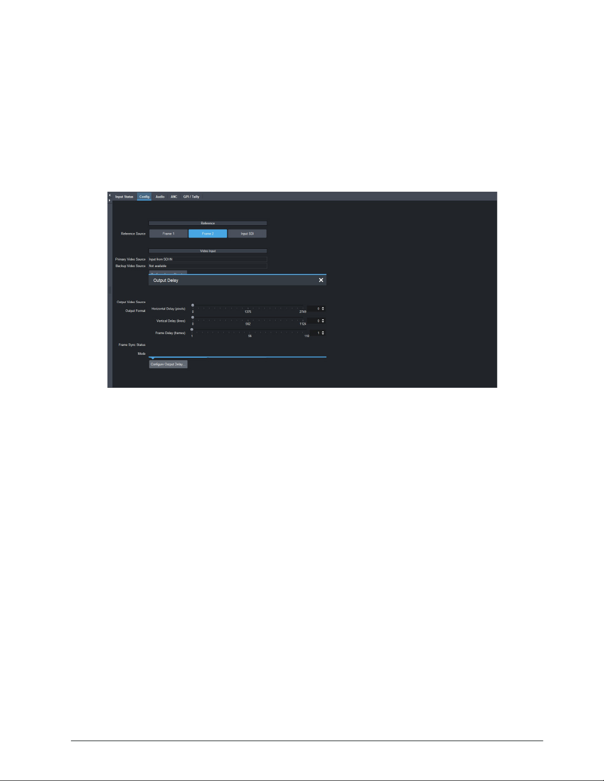
4. Click Configure Output Delay.
The Output Delay dialog opens.
5. Use the Horizontal Delay field to specify the horizontal delay, relative to the selected
reference. Adjustments are made in pixel increments.
6. Use the Vertical Delay field to specify the vertical delay, relative to the selected reference.
Adjustments are made in line increments.
7. Use the Frame Delay field to specify the delay in number of frames. Frame delay adjustments
are made in full frame increments.
8. Close the Output Delay dialog.
AMX-8952 Series User Guide (v5.0) Frame Sync Configuration • 45
Page 46

46 • Frame Sync Configuration AMX-8952 Series User Guide (v5.0)
Page 47
Embedded Audio Setup
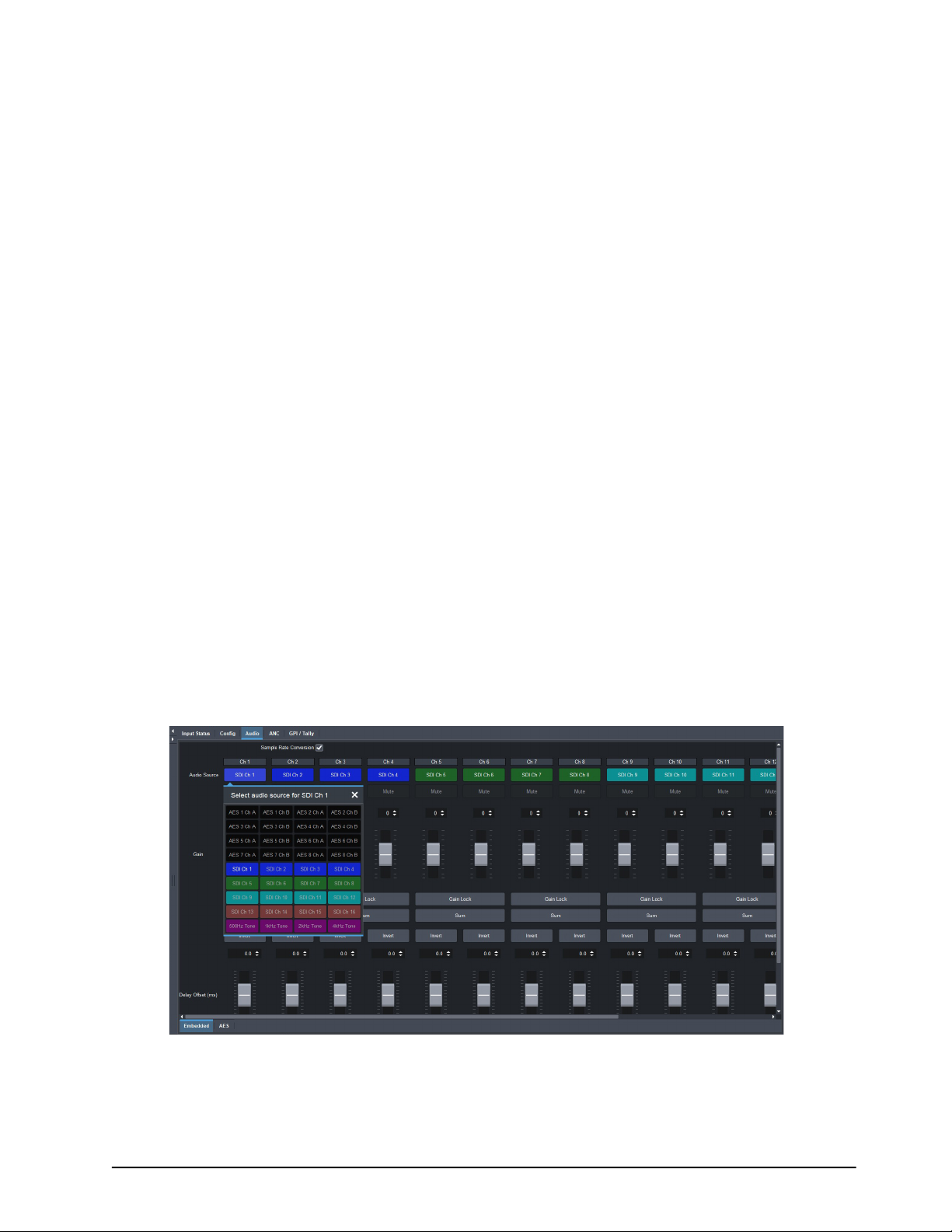
The AMX-8952 includes Processing Amplifiers (Proc Amps) for the audio inputs on the card.
Sample Rate Conversion
Integrated sample rate converters can convert audio sample rates of up to 192kHz on the SDI IN
BNC. The sample rate converters will convert the audio to the video reference rate.
To enable sample rate conversion on the AMX-8952
1. Display the AMX-8952 interface as outlined in “To access the AMX-8952 interfaces in
DashBoard”.
2. Select the Audio tab.
The Embedded sub-tab is automatically selected.
3. Select the Sample Rate Conversion box.
Mapping the Embedded Audio Channels
The embedded output channels are configured per processed input to allow different audio
mapping that will track the currently processed input.
To map a channel
1. Display the AMX-8952 interface as outlined in “To access the AMX-8952 interfaces in
DashBoard”.
2. Select the Audio tab.
The Embedded sub-tab is automatically selected.
3. From the associated Audio Source menu, select an audio source.
In the example below, the user is assigning the source for Channel 1 on an AMX-8952-B.
If the selected source is not present on the input video, silence is embedded.
Channel status bits are only passed when a left/right pair are not separated. Otherwise, a
standard channel status will be inserted. When channel status is passed, it may not reflect a
change between 20bit and 24bit.
AMX-8952 Series User Guide (v5.0) Embedded Audio Setup • 47
Page 48
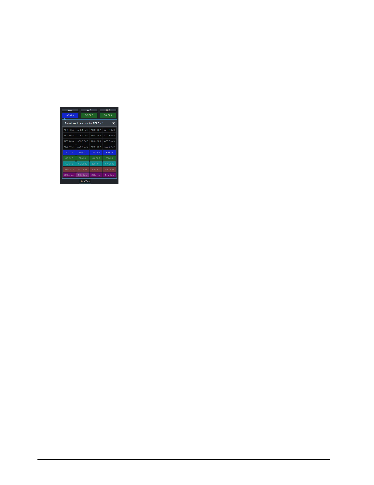
To insert test tones
1. Display the AMX-8952 interface as outlined in “To access the AMX-8952 interfaces in
DashBoard”.
2. Select the Audio tab.
The Embedded sub-tab is automatically selected.
3. From the associated Audio Source menu, select a test tone.
In the example below, the user is assigning a 1kHz test tone to Channel 4 on a AMX-8952-B.
To mute a specific channel
• Click Mute.
Proc Amps for Embedded Audio
Proc Amp adjustments are applied in the following order:
1. Sum — This option enables both channels to carry the average of the two input channels
((A+B)/2). When the input is summed, the original signals are no longer available for output. This
option only operates with AES input pairs.
2. Delay — This option enables you to adjust the delay of the audio channel. If you have enabled
the Delay Lock feature, changing the delay value for one channel automatically changes the
value for the other channel.
3. Gain — This option provides a +/- 20dB gain range in 1dB increments. If you have enabled the
Gain Lock feature, changing the gain value for one channel automatically changes the value for
the other channel.
4. Invert — This option enables you to invert the polarity of the audio signal for the selected
channel.
Processing the Embedded Audio Input
When passing non-PCM data (e.g. Dolby E®), ensure that input and output are synchronous and
all audio modifying settings (such as SRC, gain, and invert) are disabled or set to zero (0).
To set up processing of the embedded audio input
1. Display the AMX-8952 interface as outlined in “To access the AMX-8952 interfaces in
DashBoard”.
2. Select the Audio tab.
The Embedded Audio sub-tab is automatically selected.
3. To enable the SRC of the embedded audio, select the Sample Rate Conversion box.
48 • Embedded Audio Setup AMX-8952 Series User Guide (v5.0)
Page 49
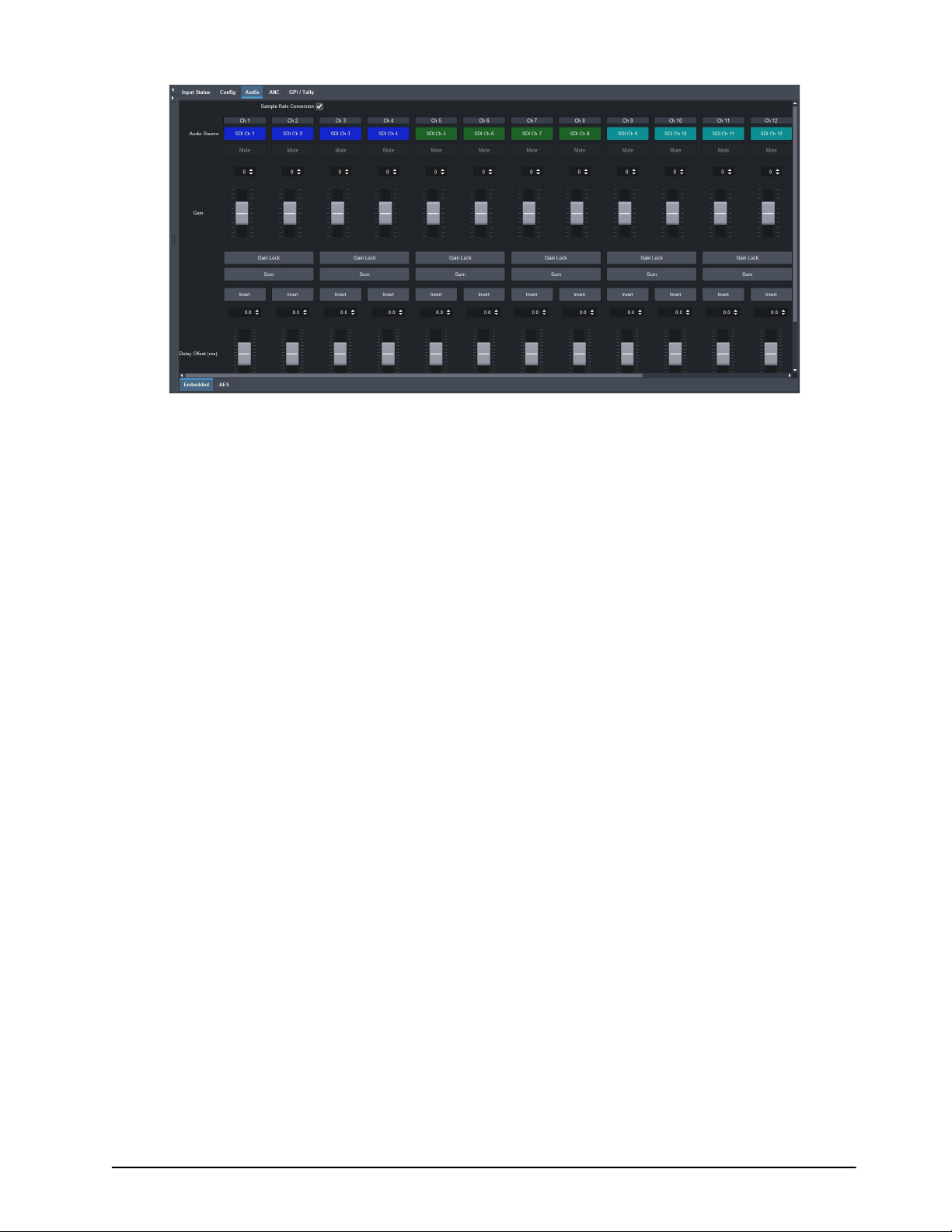
4. To apply a gain to a channel, use the associated Ch # slider to select a value between -20dB and
20dB. Repeat for each channel you wish to configure.
5. To invert a channel, select the associated Ch # Invert box.
AMX-8952 Series User Guide (v5.0) Embedded Audio Setup • 49
Page 50

50 • Embedded Audio Setup AMX-8952 Series User Guide (v5.0)
Page 51
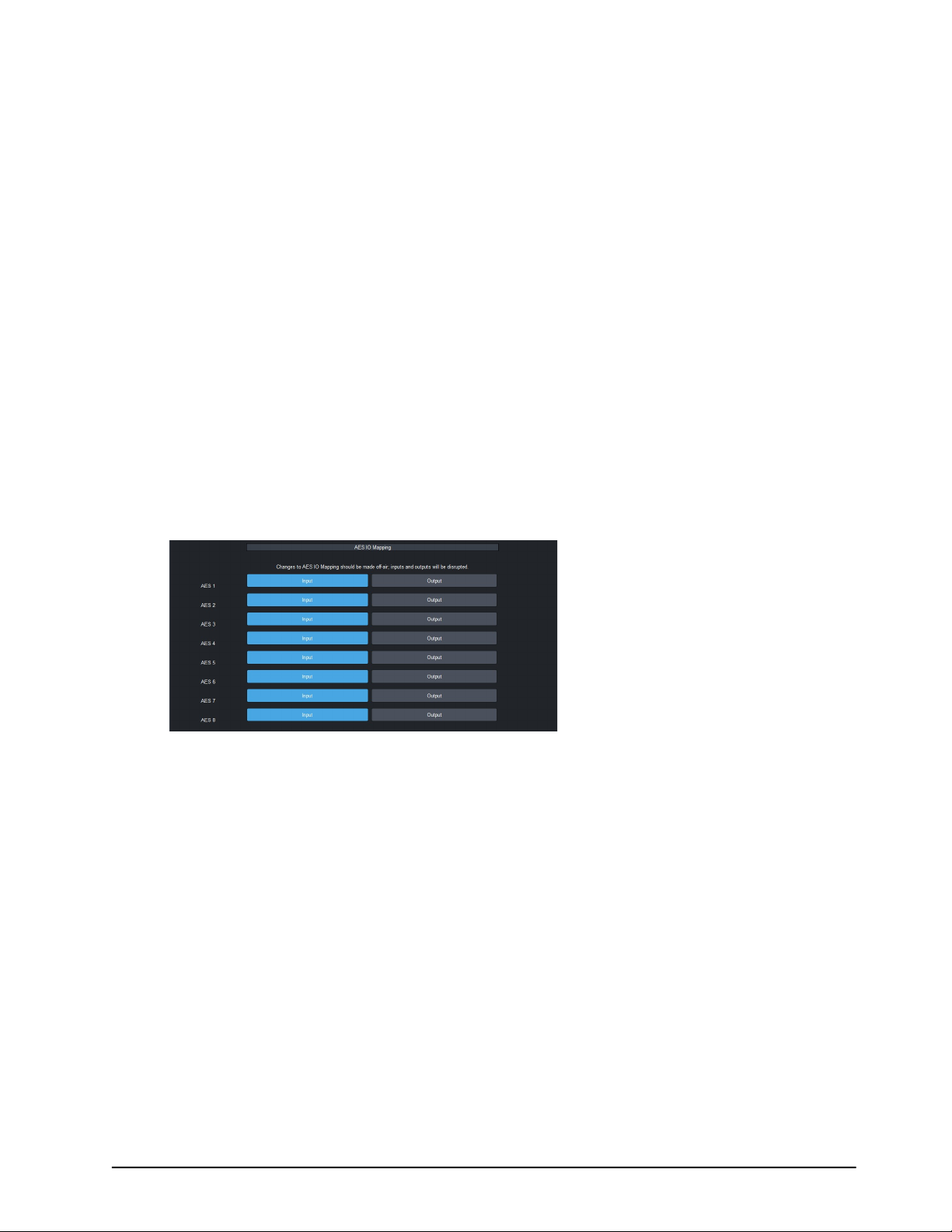
AES Setup
The AMX-8952 includes Processing Amplifiers (Proc Amps) for the audio inputs on the card.
Mapping the AES Inputs and Outputs
Before proceeding, ensure that you have made a note of the AES connections on your rear module.
This information is required when assigning a function to each AES signal.
For More Information on...
• the cabling designations for your rear module, refer to “Supported Rear Modules”.
Mapping the AES Signals
The AMX-8952 enables you to configure the AES signals independently as inputs, or outputs.
To specify the AES configuration
1. Display the Global interface as outlined in “To access the AMX-8952 interfaces in
DashBoard”.
2. Select the Setup tab.
3. Locate the AES IO Mapping area of the tab.
4. Locate the row for the AES signal you wish to configure.
5. Select one of the following:
• Input — assigns the AES signal as an input. The associated AES connector on the rear module
will receive discrete audio from an upstream source. This is the default for all AES signals.
• Output — assigns the AES signal as an output. The associated AES connector on the rear
module will transmit discrete audio to the connected external device.
6. Repeat steps 4 and 5 for each AES signal you wish to map.
Mapping the AES Channels
This section briefly summarizes how to map the AES channels. You can choose to use the default
audio channel map or assign the channels as required by your system.
To configure the AES pairs
1. Display the AMX-8952 interface as outlined in outlined in “To access the AMX-8952 interfaces
in DashBoard”.
2. Select Audio > AES.
3. Locate the column for the AES (Group) pair you wish to configure.
AMX-8952 Series User Guide (v5.0) AES Setup • 51
Page 52
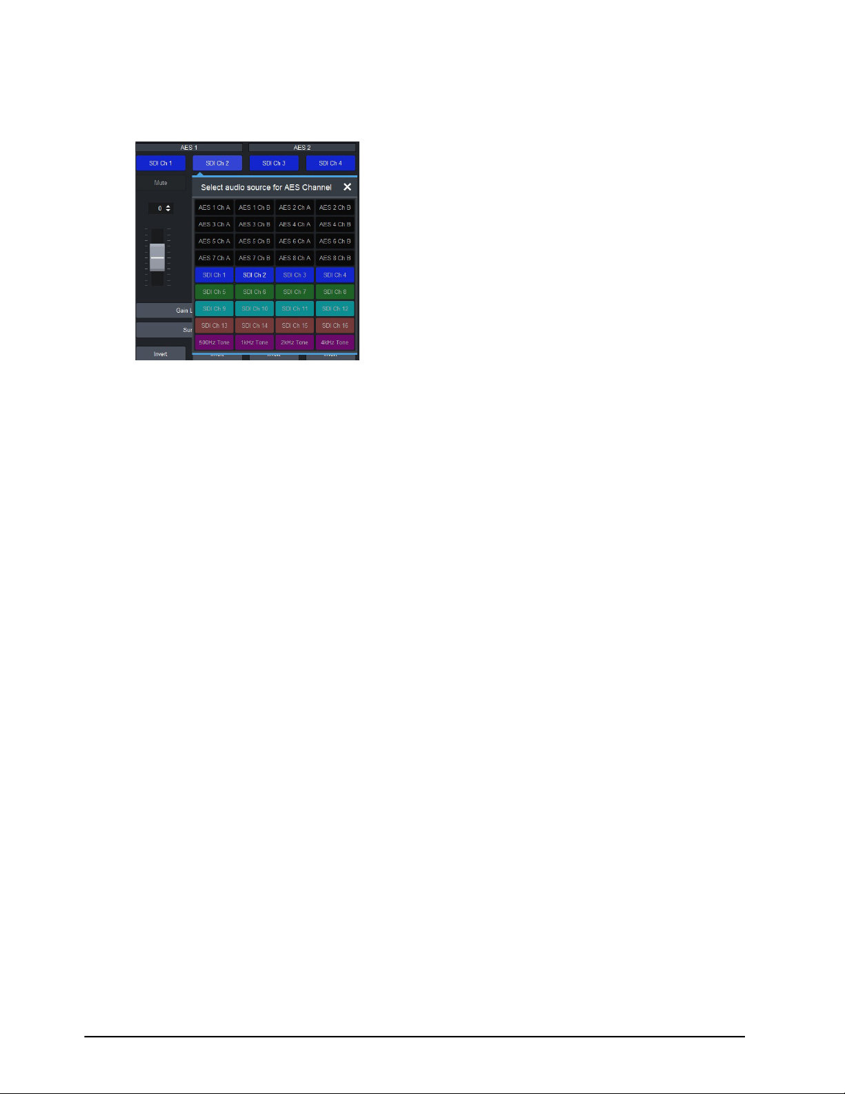
4. In the Audio Source row, select the channel of the AES pair to configure.
The Select Audio Source for AES Channel dialog opens. In the example below, the user
selected Channel 2 of AES (Group) 1.
5. Select a signal to assign it to the channel. Choose from the following:
• AES# Ch # — Assigns the specified channel of the specified AES signal.
• SDI Ch # — Assigns the specified channel from the SDI IN signal.
• #Hz Tone — Assigns the specified test tone.
In the example above, the user assigns Channel 2 from AES 2 to the channel selected in step 4.
6. Close the Select Audio Source for AES Channel dialog.
7. Repeat the procedure for each channel you wish to configure.
Using the Audio Proc
Audio Proc Amp adjustments are applied in the following order:
1. Sum — This option enables both channels to carry the average of the two input channels
((A+B)/2). When the input is summed, the original signals are no longer available for output. This
option only operates with AES input pairs.
2. Delay — This option enables you to adjust the delay of the audio channel. If you have enabled
the Delay Lock feature, changing the delay value for one channel automatically changes the
value for the other channel.
3. Gain — This option provides a +/- 20dB gain range in 1dB increments. If you have enabled the
Gain Lock feature, changing the gain value for one channel automatically changes the value for
the other channel.
4. Invert — This option enables you to invert the polarity of the audio signal for the selected
channel.
To set up processing of the AES audio input
1. Display the AMX-8952 interface as outlined in “To access the AMX-8952 interfaces in
DashBoard”.
2. Select Audio > AES.
52 • AES Setup AMX-8952 Series User Guide (v5.0)
Page 53
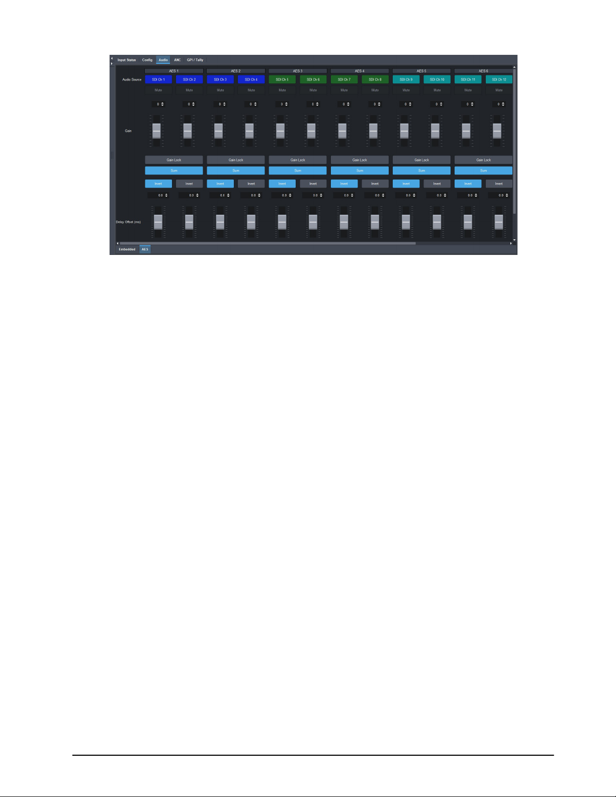
3. To mute a channel, click the associated Mute button.
4. To apply a gain to a channel, use the associated Gain Ch # slider to select a value between
-20dB and 20dB. Repeat for each channel you wish to configure.
Click Gain Lock to change the gain value for one channel and automatically change the value for
the other channel of the AES pair.
5. To sum the input ((A+B)/2) of the AES pair, click the associated Sum button.
6. To invert a channel, select the associated Ch # Invert box.
7. To set the delay for a channel of an AES pair, use the associated Delay Offset slider to specify a
value between 0ms and 500ms.
AMX-8952 Series User Guide (v5.0) AES Setup • 53
Page 54

54 • AES Setup AMX-8952 Series User Guide (v5.0)
Page 55
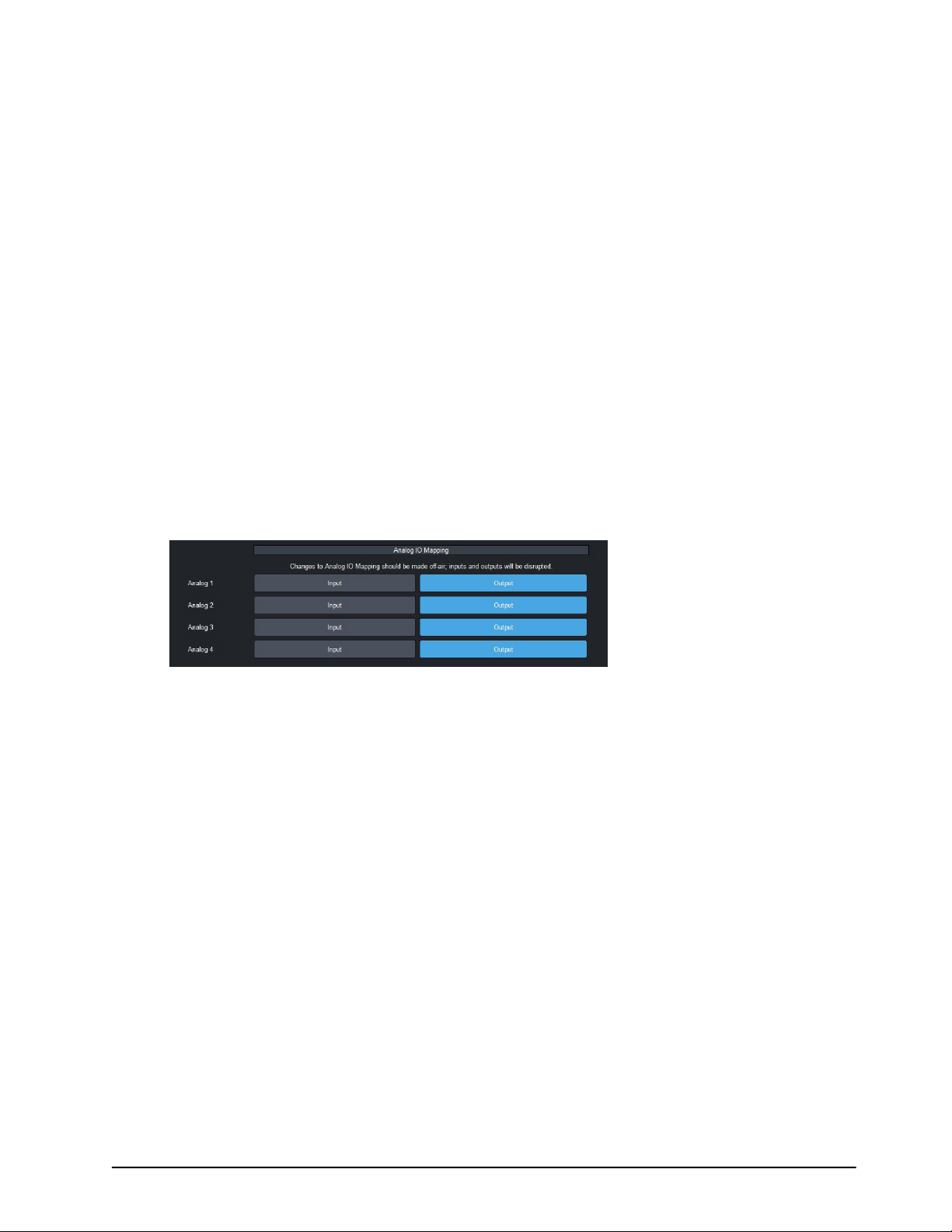
Analog Audio Setup
The AMX-8952-C includes Processing Amplifiers (Proc Amps) for the audio inputs on the card.
Mapping the Analog Inputs and Outputs
Before proceeding, ensure that you have made a note of the analog connections on your rear
module. This information is required when assigning a function to each analog signal.
For More Information on...
• the cabling designations for your rear module, refer to “Supported Rear Modules”.
Mapping the Analog Signals
The AMX-8952-C enables you to configure the analog signals independently as inputs, or outputs.
To specify the analog configuration
1. Display the Global interface as outlined in “To access the AMX-8952 interfaces in
DashBoard”.
2. Select the Setup tab.
3. Locate the Analog IO Mapping area of the tab.
4. Locate the row for the analog signal you wish to configure.
5. Select one of the following:
• Input — assigns the analog signal as an input. The associated ANLG connector on the rear
module will receive audio from an upstream source. This is the default for all analog signals.
• Output — assigns the analog signal as an output. The associated ANLG connector on the rear
module will transmit audio to the connected external device.
6. Repeat steps 4 and 5 for each analog signal you wish to map.
Mapping the Analog Channels
This section briefly summarizes how to map the analog channels. You can choose to use the default
audio channel map or assign the channels as required by your system.
To configure the analog pairs
1. Display the AMX-8952 interface as outlined in outlined in “To access the AMX-8952 interfaces
in DashBoard”.
2. Select Audio > Analog.
3. Locate the column for the analog (Group) pair you wish to configure.
4. In the Audio Source row, select the channel of the analog pair to configure.
AMX-8952 Series User Guide (v5.0) Analog Audio Setup • 55
Page 56
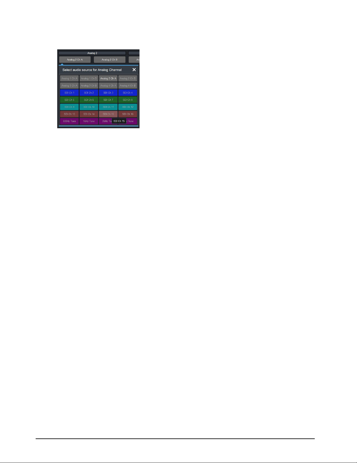
The Select Audio Source for Analog Channel dialog opens. In the example below, the user
selected Analog 2 Ch A.
5. Select a signal to assign it to the channel. Choose from the following:
• Analog # Ch # — Assigns the specified channel of the specified analog signal.
• SDI Ch # — Assigns the specified channel from the SDI IN signal.
• #Hz Tone — Assigns the specified test tone.
In the example above, the user assigns SDI Ch 15 to the channel selected in step 4.
6. Close the Select Audio Source for Analog Channel dialog.
7. Repeat the procedure for each channel you wish to configure.
Using the Audio Proc
Audio Proc Amp adjustments are applied in the following order:
1. Sum — This option enables both channels to carry the average of the two input channels
((A+B)/2). When the input is summed, the original signals are no longer available for output. This
option only operates with analog input pairs.
2. Delay — This option enables you to adjust the delay of the audio channel. If you have enabled
the Delay Lock feature, changing the delay value for one channel automatically changes the
value for the other channel.
3. Gain — This option provides a +/- 20dB gain range in 1dB increments. If you have enabled the
Gain Lock feature, changing the gain value for one channel automatically changes the value for
the other channel.
4. Invert — This option enables you to invert the polarity of the audio signal for the selected
channel.
To set up processing of the analog audio input
1. Display the AMX-8952 interface as outlined in “To access the AMX-8952 interfaces in
DashBoard”.
2. Select Audio > Analog.
56 • Analog Audio Setup AMX-8952 Series User Guide (v5.0)
Page 57
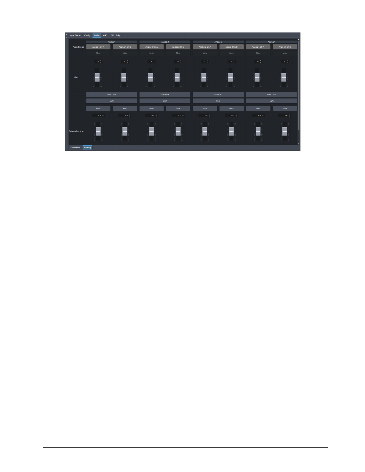
3. To mute a channel, click the associated Mute button.
4. To apply a gain to a channel, use the associated Gain Ch # slider to select a value between
-20dB and 20dB. Repeat for each channel you wish to configure.
Click Gain Lock to change the gain value for one channel and automatically change the value for
the other channel of the analog pair.
5. To sum the input ((A+B)/2) of the analog pair, click the associated Sum button.
6. To invert a channel, select the associated Ch # Invert box.
7. To set the delay for a channel of an analog pair, use the associated Delay Offset slider to
specify a value between 0ms and 500ms.
AMX-8952 Series User Guide (v5.0) Analog Audio Setup • 57
Page 58

58 • Analog Audio Setup AMX-8952 Series User Guide (v5.0)
Page 59

Ancillary Data
Ancillary Data (ANC) is the non-video data that can be embedded within the SDI signal, such as
audio, audio metadata, timecode, closed caption data, AFD, and payload identification. This chapter
provides an overview of how the AMX-8952 manages ANC data.
Overview
There are two areas in which ancillary data may be found:
• HANC — ANC packets that are found in the horizontal blanking region.
• VANC — ANC packets that are found in the vertical blanking region.
This section outlines how to view incoming status in the Input Status tab and configure the
AMX-8952 to manage HANC and VANC data using the options in the ANC tab of DashBoard.
HANC and VANC Status
The Input Status tab in DashBoard provides HANC and VANC status details:
• Embedded Audio — These fields indicate the information extracted from the channel status,
such as PCM/Non-PCM, 20bit or 24bit. When this field is blank, the packet for the specified group
is absent.
• ST 352 Upstream — This read-only field reports whether the 352M data is detected on the input,
and displays the four bytes.
• AFD, Closed Captioning, Timecode, Compressed Audio Metadata, SCTE-104, Other — These
fields indicate the status of the specified packet, such as whether it is detected or not on the
input. Each message includes the following information:
› Field # — indicates which field the timecode was detected in (e.g. Field 1 (Odd))
› Type — indicates the type of timecode (e.g. ATC-VITC1)
› Line # — indicates the specific line the timecode data was detected in (e.g. 16)
› Location — indicates timecode is in the HANC (H), or VANC (<blank>)
› Channel — indicates timecode is in the luma (L), or chroma (C) channel
CEA-708/CEA-608 Closed Captioning
The AMX-8952 series card:
• ensures continuity of CEA-608 data and/or DTVCC data during frame drop or repeat.
• receives the packet, and passes it through on the specific line or deletes it as specified in the
Action menu.
• monitors the CDP sequence number of incoming CEA-708 data to detect discontinuities in the
DTVCC transport stream, and propagates any sequence-number discontinuity to the outgoing
DTVCC data, to alert downstream equipment of the change.
When disabled, closed captioning (packet and line 21) is not inserted.
CEA-608 and CEA-708 Captioning Priority
There are two supported types of closed captioning data: native CEA-708, and CEA-608 embedded
in CEA-708. The order of preference for output CEA-708 data is as follows:
AMX-8952 Series User Guide (v5.0) Ancillary Data • 59
Page 60

1. CEA-708
2. CEA-608 embedded in CEA-708
The order of preference for output CEA-608 data is as follows:
1. CEA-608 embedded in CEA-708
2. Null content
CEA-708 is not down-converted to CEA-608.
Other Data Types
This section provides additional information on other data types that the AMX-8952 series
manages.
Compressed Audio Metadata
Compressed Audio Metadata can be passed or deleted.
Timecode
The user can specify whether timecode is passed or deleted. When pass is enabled, the timecode
will be inserted in the HANC (RP196) for all formats.
Other Packets
All remaining packets can be passed or deleted. When pass is enabled, the packets will be inserted
in VANC on the specified line in the same order as they were received. If they do not fit on the
specified line, they will continue on the next line. Approximately up to 250 packets, or 1500 bytes of
data, can be passed this way.
Passing or Deleting ANC Data
For each packet type, the user can specify whether ancillary data is inserted or deleted in the
output, and the insertion position.
To configure the card for specific ANC types
1. Display the AMX-8952 interface as outlined in “To access the AMX-8952 interfaces in
DashBoard”.
2. Select the ANC tab.
3. For each packet, use the Action options to specify whether the card passes the ANC data
unmodified or deletes the ANC data.
In the following example, the user selected to pass all types of ANC data (each Pass button is lit
blue on the interface).
60 • Ancillary Data AMX-8952 Series User Guide (v5.0)
Page 61
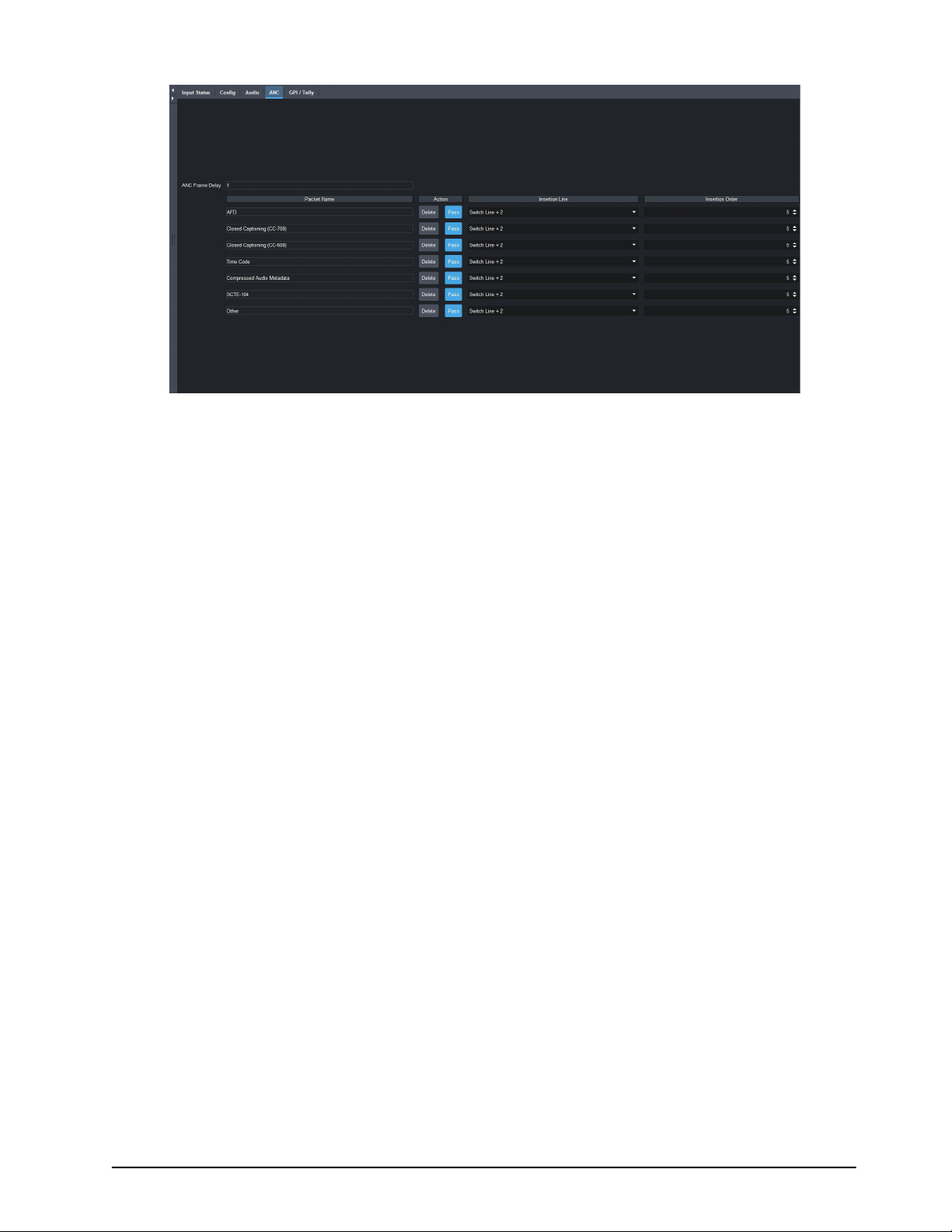
4. Use the Insertion Line menu to select a line to insert the specified ANC packet on. The default
is 9 for each packet. Note that all packets are inserted in VANC, except for timecode in non-SD
formats which are inserted in the HANC.
If more than one packet is to be inserted in the same line, the packet with the lowest insertion
order number will be inserted first.
5. Use the Insertion Order menu to define the hierarchy of the packets insertion.
The lower the number, the higher priority the packet is given. For example, if the AFD packet is to
be inserted before the Compressed Audio Metadata, set the AFD Insertion Order to 1, and the
Compressed Audio Metadata to 2.
AMX-8952 Series User Guide (v5.0) Ancillary Data • 61
Page 62

62 • Ancillary Data AMX-8952 Series User Guide (v5.0)
Page 63

Configuring the GPI/Tallies
This chapter outlines how to configure each General Purpose Interface (GPI) independently on the
AMX-8952.
GPI Communication Setup
When configured as a GPI, a port behaves as an input, and can be used to trigger actions. An
example of a commonly used GPI input is the small, hand-held, trigger a weather forecaster uses to
advance though the different backgrounds in the weather forecast. A push-button switch, or an
ON-OFF switch, may be directly connected between the port and the adjacent ground pin.
Alternatively, an external device may drive a low level. Minimum pulse duration is 1ms, anything
shorter will be filtered out.
Typically, users will configure the GPI for Edge trigger. This means that the action is carried out
either on the falling edge (button is pushed), or rising edge (button is released), depending on which
Polarity is selected. Alternatively, users may configure the GPI for Level trigger. In this mode, the
action is carried out on both the rising and falling edges, so there are effectively two states. The
Polarity control can be used to invert the behavior. Regardless of the trigger type, GPI commands
may be overridden by other command inputs such as serial protocols.
The Edge option enables the GPI to act as a latching trigger. Edge triggers are used when you want
to toggle between settings. This option enables the GPI to execute a specific function.
• If configured for Falling Edge, the selected function is executed when the GPI input signal
transitions from High to Low.
• If configured for Rising Edge, the selected function is executed when the GPI input signal
transitions from Low to High.
• Edge triggered GPI signals are sampled once per frame and the associated function is executed
only once per frame. The minimum pulse width is 1 millisecond.
• Typically, the edge triggered GPI is driven by external equipment that generates one pulse per
event.
Level triggers are used when you want to assert a particular state for a setting.
• If configured for Active Low, the selected function is executed when the GPI input signal is driven
Low.
• If configured for Active High, the selected function is executed when the GPI input signal is driven
High.
Configuring a Port as a GPI
Each port can be configured independently from the others, allowing you to customize the function
of each connection.
To configure a port as a GPI
1. Display the AMX-8952 interface as outlined in “To access the AMX-8952 interfaces in
DashBoard”.
2. Select the GPI/Tally tab.
AMX-8952 Series User Guide (v5.0) Configuring the GPI/Tallies • 63
Page 64
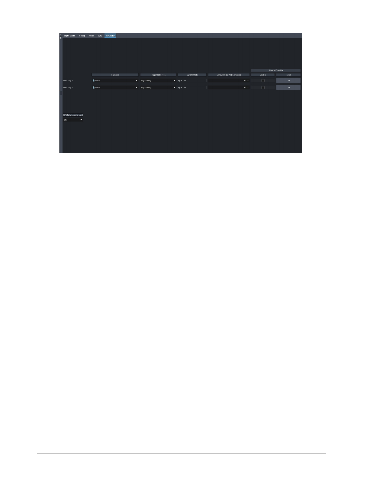
3. Use the Function menu to assign a transition event to a specific GPI port.
4. Use the Trigger/Tally Type menu to select a trigger and polarity for the GPI.
5. Use the Manual Override and Level options in conjunction to override a GPI.
a. Select the Manual Override box for a GPI/Tally.
b. Toggle the Level button.
Tally Communication Setup
When configured as a Tally, a port becomes an output, providing a status indicator. Typically this is
used to indicate which input(s) are on-air at any given moment. Each tally output on the card can be
configured to be active when an input is on air. They can be configured as Active High or Active Low.
Edge triggered tallies generate a pulse to the configure polarity (high or low) for a duration of 30
frames or the duration of the event (whichever is shorter). The tally outputs defaults to a logical
high level when inactive. When the tally becomes active, for example the signal is on-air, then the
output is driven low.
To configure a port as a tally
1. Display the AMX-8952 interface as outlined in “To access the AMX-8952 interfaces in
DashBoard”.
2. Select the GPI/Tally tab.
3. Use the Function menu to specify what will drive the tally output when the input is on-air.
4. Use the Trigger/Tally Type menu to select the polarity of the tally.
5. Use the Manual Override and Level options in conjunction to override a tally.
a. Select the Manual Override box for a GPI/Tally.
b. Toggle the Level button.
64 • Configuring the GPI/Tallies AMX-8952 Series User Guide (v5.0)
Page 65

Upgrading the Software
The AMX-8952 can be upgraded in the field via DashBoard.
To upgrade the software on a card
1. Contact Ross Technical Support for the latest software version file.
2. Ensure the Ethernet cable is connected to the Ethernet port on the openGear frame.
3. From the Tree View, expand the node for the AMX-8952 you want to access.
4. Double-click the Global sub-node to display the interface in the right-half of DashBoard.
5. Select Upload, located near the bottom of the interface, to display the Select file Upload
dialog.
6. Navigate to the *.bin file you want to upload.
7. Click Open.
8. If you are upgrading a single card:
a. Click Finish to start the upgrade.
b. Proceed to step 10.
9. If you are upgrading multiple cards:
a. Click Next > to display the Select Destination menu. This menu provides a list of the
compatible cards.
b. Specify the card(s) to upload the file to by selecting the check box(es) for the cards you want
to upload the file to.
c. Verify the card(s) you want to upload the file to. The Error/Warning fields indicate any
errors, such as incompatible software or card type mismatch.
d. Click Finish.
10. Monitor the upgrade.
• An Upload Status dialog enables you to monitor the upgrade process.
• Notice that each card is listed in the dialog with a button. This button is replaced with a
Reboot button once the software file is loaded to that card.
Avoid clicking the individual Reboot buttons until all cards have successfully completed the file
upload process and the OK button, located in the bottom right corner of the dialog, is enabled.
• Click OK to reboot all the cards listed in the Uploading to Selected Devices dialog.
• The Reboot Confirm dialog displays, indicating the number of cards that will reboot. Click
Yes to continue the upgrade process. Note that clicking Cancel or No returns you to the
Uploading to Selected Devices dialog without rebooting the card(s).
• The card(s) are temporarily taken off-line during the reboot process. The process is complete
once the status indicators for the Card State and Connection return to their previous status.
AMX-8952 Series User Guide (v5.0) Upgrading the Software • 65
Page 66

66 • Upgrading the Software AMX-8952 Series User Guide (v5.0)
Page 67
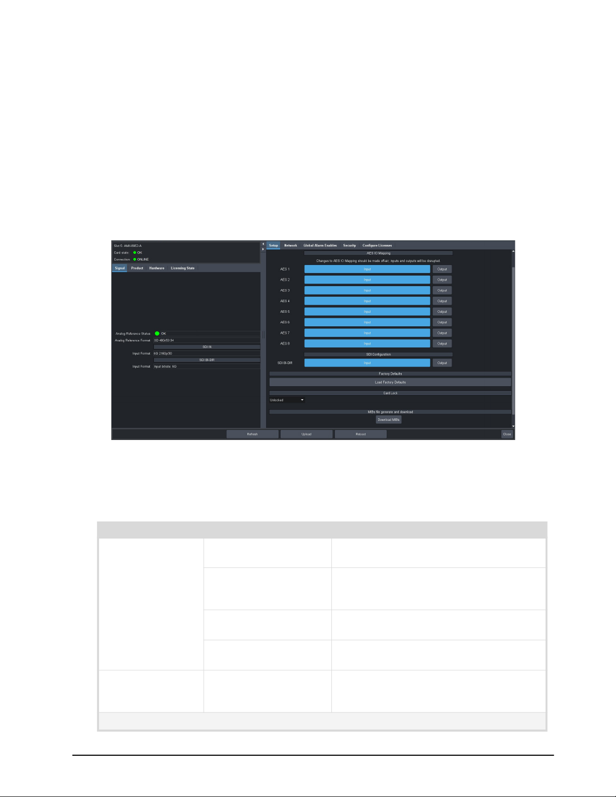
DashBoard Menus
This chapter briefly summarize the menus, items, and parameters available from the DashBoard
Control System for the AMX-8952. Parameters marked with an asterisk (*) are the factory default
values.
Wait 30 seconds after the last setting change to ensure all changes are saved to the non-volatile
memory of the card.
Global Interface
The Global interface is accessed by double-clicking the Global sub-node in the AMX-8952 tree. There
are two distinct areas in the Global interface: Status (on the left), and Configuration (on the right).
Figure 1 Example of the Global Interface — AMX-8952-A
Signal Tab
Table 1 summarizes the read-only fields displayed in the Signal tab.
Table 1 Signal Tab
Item Parameters Description
Analog Reference
Status
Analog Reference
Format
SDI IN
OK (Green) A valid signal is detected from the reference
source device
Alarm suppressed
(Green)
Unsupported An unsupported signal is detected from the
Unlocked (Red) A valid or present reference signal is not
# Reports the video format detected on the
There are reference errors detected but the
Global Alarm Enables > Reference Error
option is disabled (box is not selected)
reference source device
detected by the card
input reference signal as defined by the
Setup > Analog Reference Source menu.
AMX-8952 Series User Guide (v5.0) DashBoard Menus • 67
Page 68
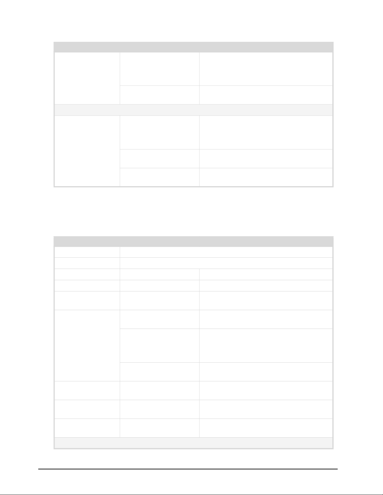
Table 1 Signal Tab
Item Parameters Description
Input Format # A valid signal is detected on the active SDI
input, the format is supported, and the
selected reference signal is supported and
compatible
N/A An invalid SDI signal is detected on the
active SDI input
SDI BI-DIR
Input Format # A valid SDI signal is detected on the SDI
BI-DIR BNC, the format is supported, and
the selected reference signal is supported
and compatible
Input bitrate: 12G A 12G signal is detected on the SDI BI-DIR
BNC
N/A An invalid SDI signal is detected on the SDI
BI-DIR BNC
Product Tab
Table 2 summarizes the read-only information displayed in the Product area.
Table 2 Product Tab
Item Parameters Description
Product AMX-8952-#
Supplier Ross Video Ltd.
Board Rev # Indicates the hardware version
Serial Number # Indicates the serial number of the card
Rear Module # Indicates the rear module the card is
installed in
Rear Module Status OK (Green) A supported rear module is installed with
the card
Alarm suppressed
(Green)
Incomp I/O Module (Red) Card is connected to an unsupported rear
Software Rev #.#-# Indicates the software version running on
Firmware Rev #.# Indicates the firmware version running on
An unsupported rear module is installed by
the Global Alarm Enables > Incompat Rear
Module option is disabled (box is not
selected)
module
the card
the card
CPLD Rev #.# Indicates the complex programmable logic
device version of the AMX-8952
Daughter Card
68 • DashBoard Menus AMX-8952 Series User Guide (v5.0)
Page 69

Table 2 Product Tab
Item Parameters Description
Type # Indicates the daughter card model installed
Variant #
Issue # Indicates the hardware version of the
on the card
daughter card
Hardware Tab
Table 3 summarizes the read-only information displayed in the Hardware tab.
Table 3 Hardware Tab
Item Parameters Description
Hardware Status OK (Green) Fans are operating correctly; no errors are
detected
Alarm suppressed
(Green)
Critical Temperature
(Red)
Fan Off/Stalled (Red) The fan installed on the AMX-8952 is not
Voltage (mV) # Measured input millivolts
Current (mA) # Current consumption in milliamperes
Power (W) # Power consumption in watts
FPGA Temp (C) #C Indicates the FPGA Core temperature
There are fan errors detected but the
Global Alarm Enables > Stalled Fan option is
disabled (box is not selected)
The FPGA temperature is 100°C (212°F) or
above
operating correctly
where:
• A green indicator displays when the
temperature is less than 95°C.
• A yellow indicator displays when the
temperature is greater than or equal to
95°C.
• A red indicator displays when the
temperature is greater than or equal to
100°C (212°F).
If the temperature is greater than
100°C (212°F), the user must manually
power down the card.
AXI Bridge # The Advanced extensible interface bridge is
running correctly on the AMX-8952. This
information is for Ross Technical Support.
Fan Speed # Reports the speed (rpm) of the fan on the
board
AMX-8952 Series User Guide (v5.0) DashBoard Menus • 69
Page 70
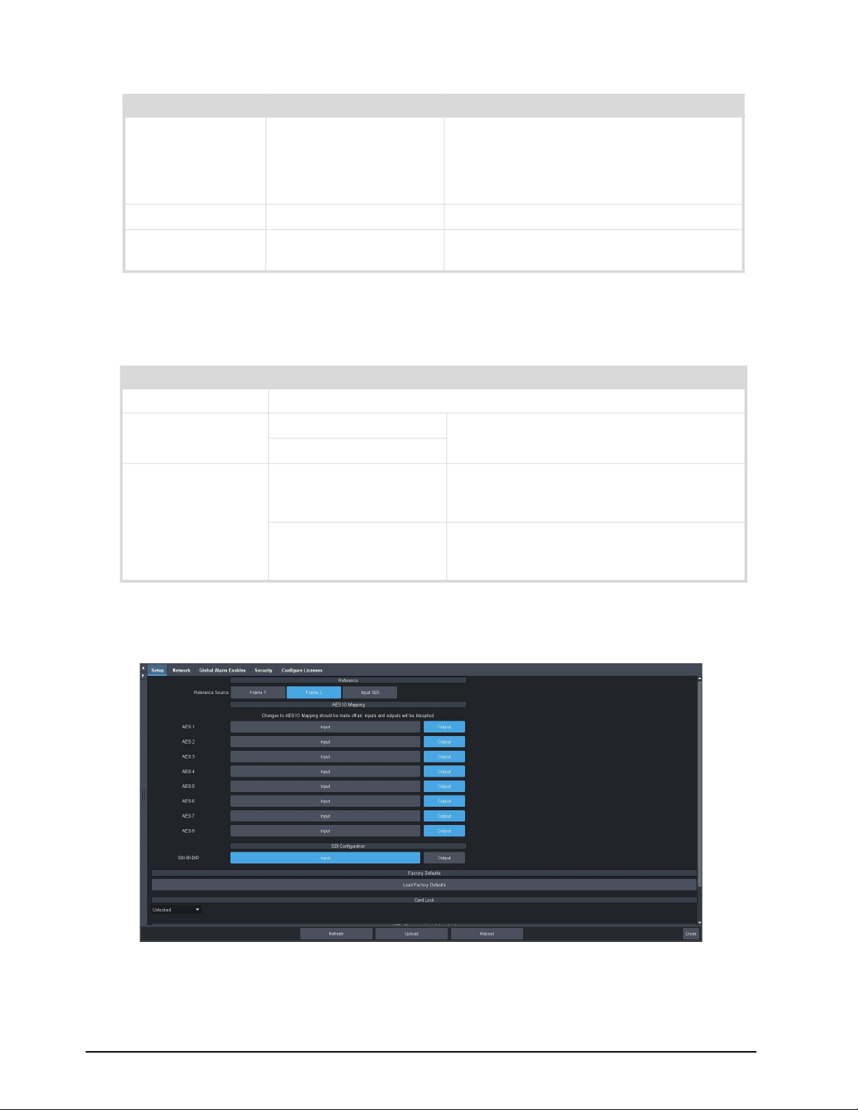
Table 3 Hardware Tab
Item Parameters Description
CPU Usage x.xx / y.yy / z.zz Displays the CPU Load average where:
• x.xx represents in the last minute
• y.yy represents the last five minutes
• z.zz represents the last fifteen minutes
RAM Available # / # MB CPU Memory Used / Total CPU Memory
SD Card Status # of #GB used Reports the amount of memory used on the
Micro SD card
Licensing State Tab
Table 4 summarizes the read-only information displayed in the Licensing State tab.
Table 4 Licensing State Tab
Item Parameters Description
Base Product Type AMX-8952
Feature AMX-8952-FS-LICENSE Lists the available licensed features for this
AMX-8952-UHD-LICENSE
License State Unlicensed The license key for the feature is not
base product type
installed. Navigate to the Configure License
tab to enable this feature
Licensed The license key for the AMX-8952+FRC
feature was correctly enabled in the
Configure License tab
Setup Tab
The Setup tab is the first tab in the Configuration pane of the Global interface.
Figure 2 Global — Setup Tab for the AMX-8952-A
70 • DashBoard Menus AMX-8952 Series User Guide (v5.0)
Page 71
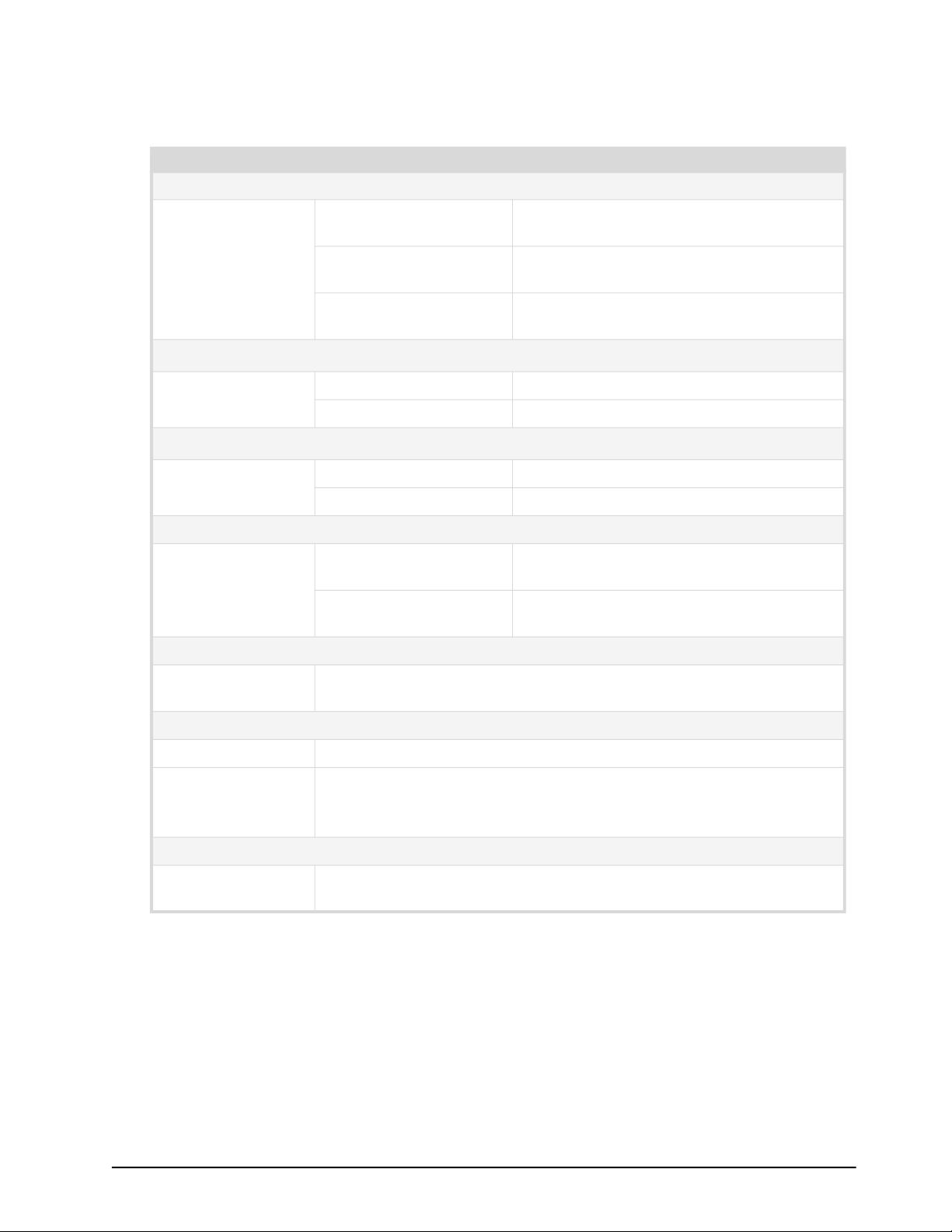
Table 5 summarizes the options displayed in the Setup tab.
Table 5 Setup Tab
Item Parameters Description
Reference
Reference Source Frame 1 Uses the reference signal connected to the
REF 1 BNC on the openGear frame
Frame 2 Uses the reference signal connected to the
REF 2 BNC on the openGear frame
Input SDI Uses the video signal connected to the SDI
IN port on the rear module
AES IO Mapping
a
AES # Input Assigns the AES port as an input
Output Assigns the AES port as an output
Analog IO Mapping
b
Analog # Input Assigns the ANLG port as an input
Output Assigns the ANLG port as an output
SDI Configuration
SDI BI-DIR Input Assigns the SDI BI-DIR port (BNC 3) on the
rear module as an input
Output* Assigns the SDI BI-DIR port (BNC 3) on the
rear module as an output
Factory Defaults
Load Factory
Defaults
All editable parameters in DashBoard, except those in the Network tab,
are reset to the factory default values
Card Lock
Unlocked* All editable parameters in DashBoard can be modified by a user
Locked The DashBoard interface is locked. The editable parameters in
DashBoard can no longer be modified by the user.
To unlock the interface, select the box again.
Generate and Download MIBs File
Download MIBs Downloads the Management Information Base (MIB) file that provides
the SNMP controls for your card
a. This area is only available when using the AMX-8952-A or AMX-8952-B.
b. This area is only available when using the AMX-8952-C.
AMX-8952 Series User Guide (v5.0) DashBoard Menus • 71
Page 72

Network Tab
Table 6 summarizes the menus and read-only fields displayed in the Network tab.
Table 6 Network
Item Parameters Description
Remote Logging
Remote Logging #.#.#.# Specifies the IP Address for the external
device that is logging the communication
activity for the AMX-8952
Default Gateway
Current (read-only) #.#.#.# Indicates the gateway for communications
outside of the local area network (LAN)
Static Gateway #.#.#.# The Gateway for the AMX-8952 that the
user manually assigned
openGear Chassis RJ-45
Link Status
(read-only)
Current IP Address
(read-only)
Current Subnet
Mask (read-only)
MAC Address
(read-only)
Mode Static The user manually supplies the network
OK (Green) The AMX-8952 is communicating on the
network via the Network Controller Card
Invalid Subnet Mask
(Yellow)
Apply/Cancel Changes
(Yellow)
Link Down (Red) The link for the Network Controller Card is
#.#.#.# Indicates the IP Address currently assigned
#.#.#.# Indicates the subnet mask for the
# Indicates the MAC Address currently
DHCP* Automates the assignment of network
The Current Subnet Mask value is set
incorrectly or is invalid within your network
One or more setting on this tab was
changed but the Apply button was not
selected
invalid
to the AMX-8952 via the Network Controller
Card
AMX-8952
assigned to the AMX-8952
settings for the AMX-8952
settings for the AMX-8952
Static IP Address # The IP Address for the AMX-8952 that the
user manually assigned
Subnet Mask # The Subnet Mask for the AMX-8952 that the
user manually assigned
72 • DashBoard Menus AMX-8952 Series User Guide (v5.0)
Page 73
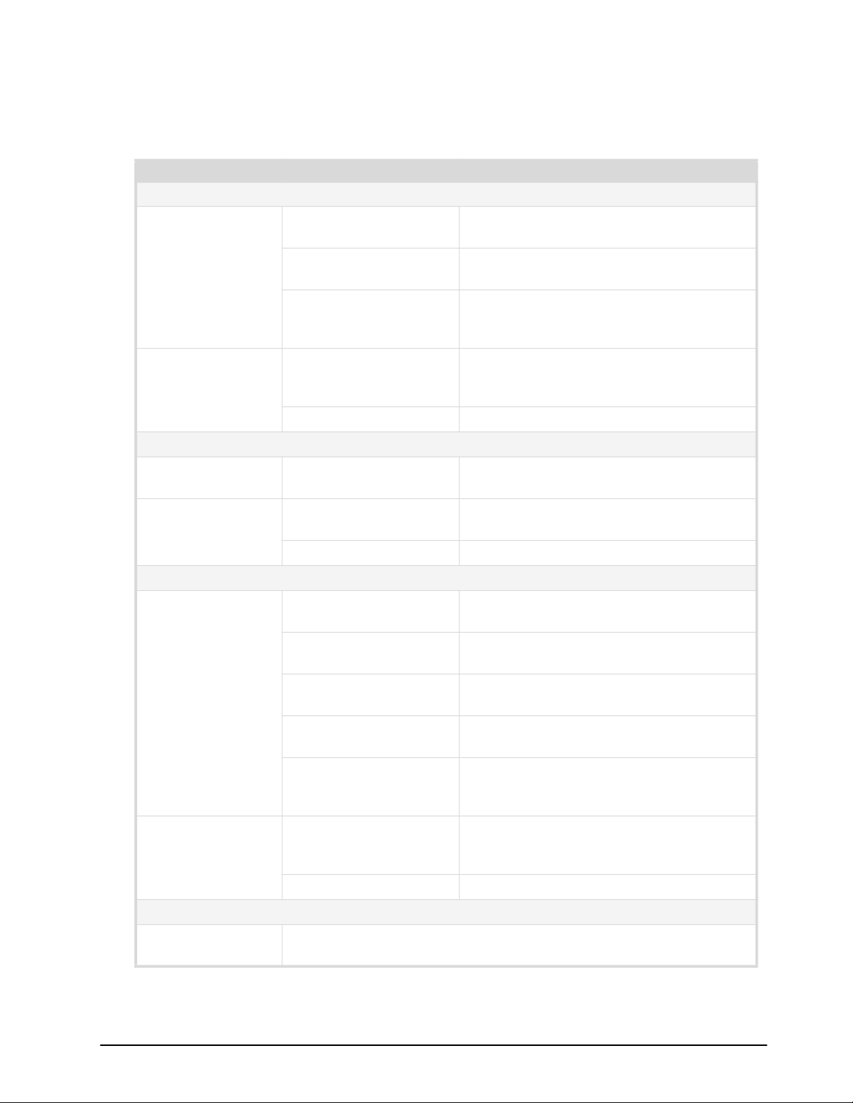
Global Alarm Enables Tab
Table 7 summarizes the options displayed in the Global Alarm Enables tab.
Table 7 Global Alarm Enables Tab
Item Parameters Description
Rear Module Alarm
Status (read-only) OK (Green) The rear module installed with the
AMX-8952 is a supported model
Alarm Suppressed
(Green)
Incompat Rear Module
(Red)
Alarm Enable Selected* The Global > Product > Rear Module Status
Cleared Disables this alarm
Fan Alarm
Fan Speed
(read-only)
Alarm Enable Selected* The AMX-8952 reports the detected speed
Analog Reference Alarm
Reference Format
(read-only)
# Reports the speed (rpm) of the fan on the
Cleared Disables this alarm
OK (Green) Indicates the detected reference format is
Alarm Suppressed
(Green)
The Alarm Enable box is cleared. The status
of the rear module will not be reported.
The rear module installed with the
AMX-8952 is not supported. Refer to
“Supported Rear Modules”.
field reports when a rear module is not
compatible with the card
board
of the fan installed on the board
supported
The Alarm Enable box is cleared. The status
of the reference signal will not be reported.
Unlocked (Red) A reference signal is detected, but the card
is not locked to it
Unsupported (Red) A reference signal is detected, but the
format is not supported by the AMX-8952
Incompatible (Red) A reference signal is detected but the
format is incompatible with the current
output mode of the card
Alarm Enable Selected* The Global > Signal > Analog Reference
Status field reports when there is a loss of
reference signal
Cleared Disables this alarm
SDI Input Alarms
Input # Status
(read-only)
AMX-8952 Series User Guide (v5.0) DashBoard Menus • 73
This field duplicates the information reported in the Input Status field
as outlined in Table 10.
Page 74

Table 7 Global Alarm Enables Tab
Item Parameters Description
Alarm Enable Selected* AMX-8952 reports a loss of the specified
input or if the format is incompatible for the
specified input
Cleared Disables this alarm
Security Tab
Table 8 summarizes the options displayed in the Security tab.
Table 8 Security Tab
Item Parameters Description
Security Configuration
SSH Login Disable* Disables the ability for a user to log onto
the AMX-8952 via a SSH server
Enable The AMX-8952 can be accessed via a secure
channel by an SSH server. This should only
be selected if directed to do so by Ross
Video Technical Support.
Configure Licenses Tab
Table 9 summarizes the read-only information displayed in the Configure Licenses tab.
Table 9 Configure Licenses Tab
Item Parameters Description
Base Product Type AMX-8952
Feature <text> Specifies the license(s) available for your
card
Request Code # This character string is used to obtain a
license key
Key # Specifies the license key that was provided
for the specified feature
74 • DashBoard Menus AMX-8952 Series User Guide (v5.0)
Page 75
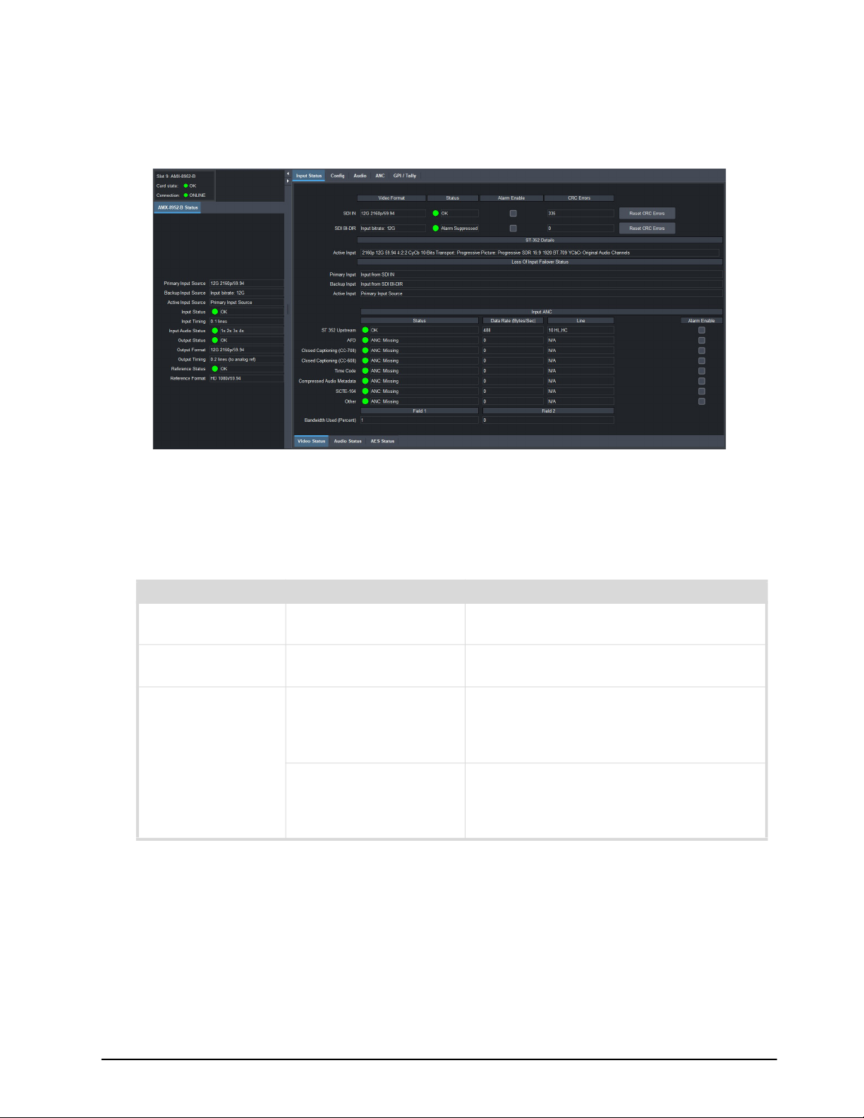
AMX-8952 Interfaces
Each AMX-8952 interface provides options for configuring and monitoring the video and audio
signals for your AMX-8952 card. The menus and tabs that are available depend on the specific card
model you are using.
Figure 3 Example of an AMX-8952-B Interface in DashBoard
AMX-8952 Status Tab
Table 10 summarizes the read-only fields displayed in the Status tab.
Table 10 AMX-8952-# — Status
Item Parameters Description
Primary Input
Source
Backup Input
Source
Active Input Source Primary Input Source Indicates that the Primary Input Source is
# Indicates the video format detected on the
active SDI input signal
# Indicates the video format (or bitrate)
detected on the backup SDI input signal
the active input signal for the card. The
signal is assigned via the Config > Primary
Video Source menu.
Backup Input Source Indicates that the Backup Input Source is
the active input signal for the card. The
signal is assigned via the Config > Backup
Video Source menu.
AMX-8952 Series User Guide (v5.0) DashBoard Menus • 75
Page 76

Table 10 AMX-8952-# — Status
Item Parameters Description
Input Status OK (Green) No errors are detected on the video signal
of the specific SDI IN BNC
Alarm suppressed
(Green)
Unsupported Format
(Yellow)
The AMX-8952 is not monitoring the input
signal(s)
An input signal is detected on the specific
SDI IN BNC but the video is not supported
by the card
Incompatible Video
(Yellow)
An input signal is detected on the specific
SDI IN BNC but its format is not compatible
with the output video format
Not time to Ref (Yellow) An input signal is detected on the specific
SDI IN BNC but the detected reference
signal is incompatible with this input signal
No Signal (Red) Indicates one of the following issues is
occurring:
• the SDI input signal is not detected
• the system frame rate does not match the
input frame rate
Input Timing Lines: #, Pixels: # Indicates the timing offset between the
video input signal and the reference signal.
The unit of measure is lines and pixels with
respect to the input video format.
Input Audio Status #a #x #s #s Indicates the input audio status where:
• # represents the audio group (e.g. 1, 2)
• a represents an async audio group
• x represents a missing audio group
• s represents a sync audio
Output Status OK (Green) Indicates that no errors are detected on the
video signal of the SDI OUT BNC
Alarm Suppressed
(Green)
Test Pattern: Color
(Green)
The card is not monitoring the output
signal(s)
The current output of the card is a SMPTE
test pattern
Matte Pattern (Green) The current output of the card is set to a
solid color as defined by the Matte Pattern
No Lock (Red) A reference signal is detected, but the card
output is not locked to it
Output Format # Indicates the output video format
Invalid Selection The output video format is not supported
or does not match the reference format
Output Timing # lines (to x) Indicates the timing offset between the
video output signal and the reference signal
where x represents the reference signal
specified in the Config > Reference Source
menu
76 • DashBoard Menus AMX-8952 Series User Guide (v5.0)
Page 77
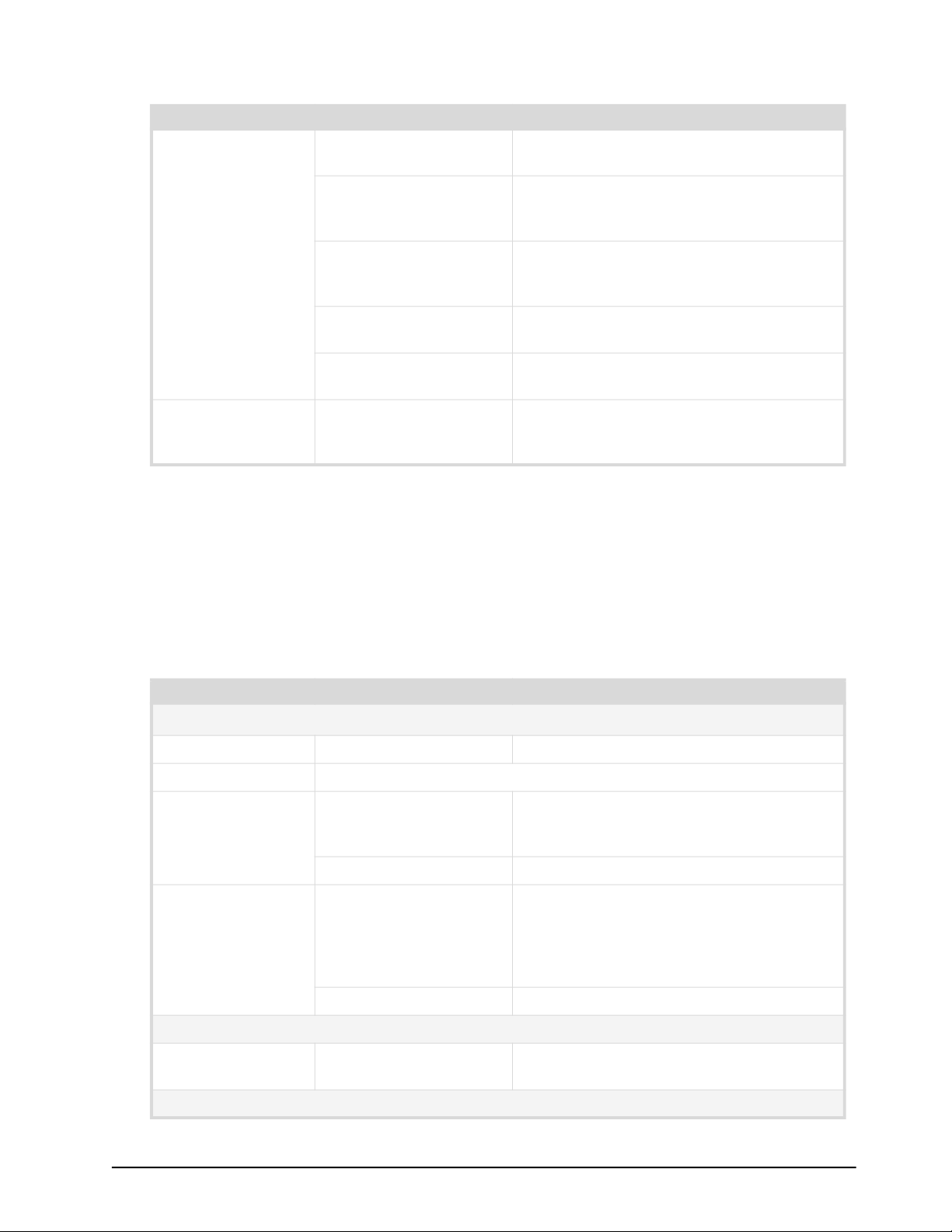
Table 10 AMX-8952-# — Status
Item Parameters Description
Reference Status OK (Green) A valid signal is detected from the reference
source device
Alarm suppressed
(Green)
There are reference errors detected but the
Global Alarm Enables > Reference Error
option is disabled (box is not selected)
Incompatible (Red) The reference signal is not compatible to
the detected input signal. Refer to Table 6
for a list of compatible signals.
Unsupported (Red) An unsupported signal is detected from the
reference source device
Unlocked (Red) A valid or present reference signal is not
detected by the card
Reference Format # Reports the video format detected on the
input reference signal as defined by the
Setup > Analog Reference Source menu
Input Status Tab
The Input Status tab provides a sub-tab to monitor each type of signal the AMX-8952 is currently
ingesting.
Video Status
Table 11 summarizes the read-only fields displayed in the Video Status tab.
Table 11 Input Status — Video Status
Item Parameters Description
SDI IN, SDI BI-DIR
a
Video Format # Indicates the detected input format/bitrate
Status (read-only) Duplicates the information reported in Table 10
Alarm Enable Selected* An alarm is reported during a loss of the
specified input or the format is
incompatible for the specified input
Cleared Disables the alarm
CRC Errors # Displays the count of the CRC errors on the
video input. This counter is reset on loss of
video, or by user request. The counter is
non-latching, and the count can roll over
the counter
Reset Resets the CRC Errors field
ST-352 Details
Active Input # 352M data is detected and the 4 bytes are
displayed
Loss of Input Failover Status
AMX-8952 Series User Guide (v5.0) DashBoard Menus • 77
Page 78

Table 11 Input Status — Video Status
Item Parameters Description
Primary Input Input from SDI # Reports the SDI signal assigned as the
primary SDI input. This is set in the Config
tab.
Backup Input Input from SDI # Reports the SDI signal assigned as the
backup SDI input. This is set in the Config
tab.
Active Input # Reports which SDI signal (Primary or
Backup) is the currently active input signal
Input ANC
Status (read-only) ANC: Present (Green) Expected incoming ANC data: present
ANC: Exceeded
Bandwidth
Captured VANC services exceeded
bandwidth
ANC: Missing Expected incoming ANC data: not present
ANC: Present in Luma
and Chroma
Incoming data was found on both LUMA
and CHROMA channels
ANC: Unexpected: Field # Receiving ANC data from wrong field
ANC: Unexpected: LUMA Receiving ANC data from wrong channel
ANC: Unexpected:
CHROMA
Receiving ANC data from wrong channel
ANC: Line Out of Range Receiving data from wrong line
ANC: Too Many Packets
in Frame
ANC: Not Assigned The required output port has not been
assigned
ANC: Not Connected The output has been assigned, but is not
connected
ANC: Overflow Exceeded output bandwidth. Lost data.
ANC: CRC Error CRC error found in incoming ANC data:
some protocols only
ANC: Parse Error Incoming data does not match expected
protocol
Status (read-only) ANC: Invalid Length The length of incoming ANC packet is
incorrect for service
Data Rate
(Bytes/Sec)
# Reports the upstream data transfer rate;
the number of bytes received in the last
field
Line # VL, VC Reports the upstream data insertion
N/A
location
Alarm Enable Selected* The AMX-8952 monitors the Input ANC
status and updates the Status field
accordingly
Cleared Disables this alarm
78 • DashBoard Menus AMX-8952 Series User Guide (v5.0)
Page 79
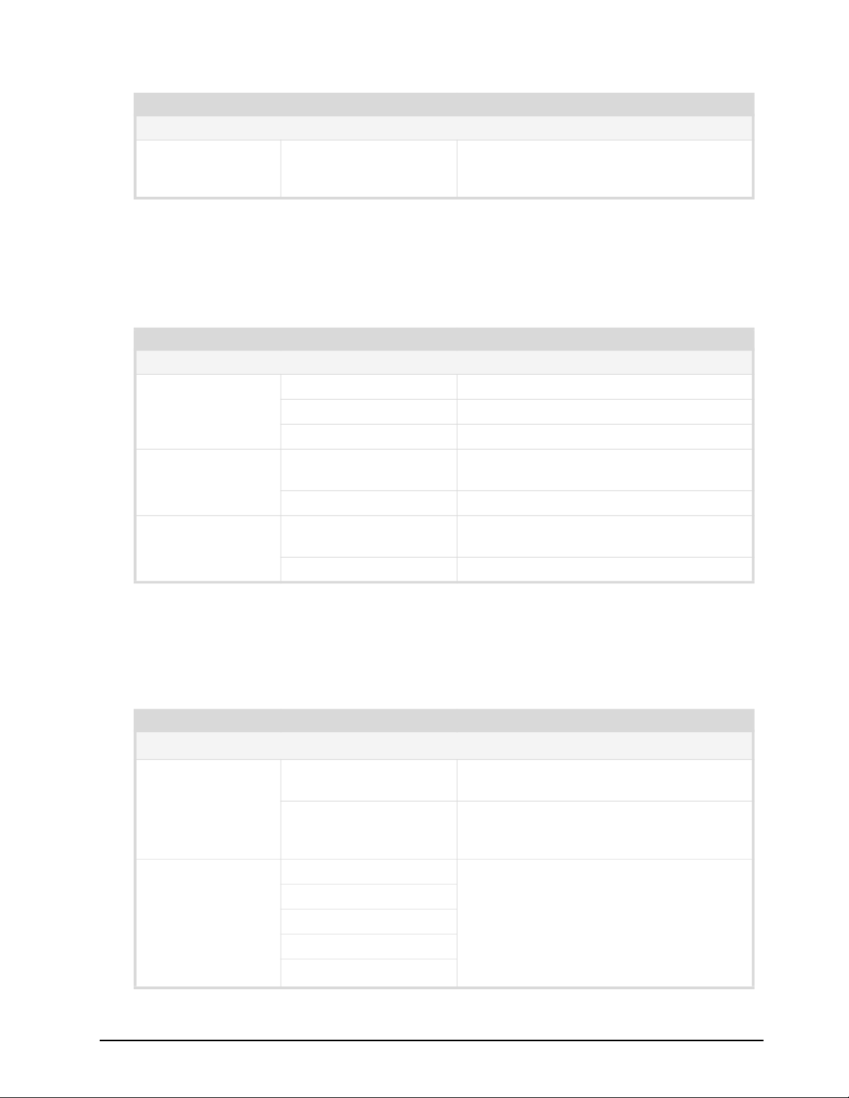
Field #
Table 11 Input Status — Video Status
Item Parameters Description
Bandwidth Used
(Percent)
# The overall bandwidth percentile including
buffer overflow state, of all incoming ANC
services on the SDI input
a. The SDI BI-DIR fields display when the SDI BI-DIR is set to Input on the Global > Setup tab.
Audio Status
Table 12 summarizes the read-only fields displayed in the Audio Status tab.
Table 12 Input Status — Audio Status
Item Parameters Description
Embedded Audio Status - Group #
Channel #
(read-only)
Async Alarm Selected* An alarm is reported when the embedded
Presence Alarm Selected* An alarm is reported when the embedded
PCM The channel is PCM audio
Non-PCM The channel is non-PCM audio
Absent The audio channel is not detected or invalid
audio is incompatible
Cleared Disables the alarm
audio is not present
Cleared Disables the alarm
AES Status
Table 13 summarizes the options, and read-only fields displayed in the AES Status tab. This tab
displays when using an AMX-8952-A or AMX-8952-B.
AES signal
AES signal. Select this option when using
non-PCM audio data.
input
Item Parameters Description
AES # Input
Sample Rate
Conversion
Ch # Status
(read-only)
Table 13 Input Status — AES Status
a
Selected SRC is used on the input of the specified
Cleared SRC is not used on the input of the specified
PCM (Green) Displays the status of the specified channel
PCM-silent (Green)
Non-PCM (Green)
No Input (Red)
b
Async
(Red)
AMX-8952 Series User Guide (v5.0) DashBoard Menus • 79
Page 80
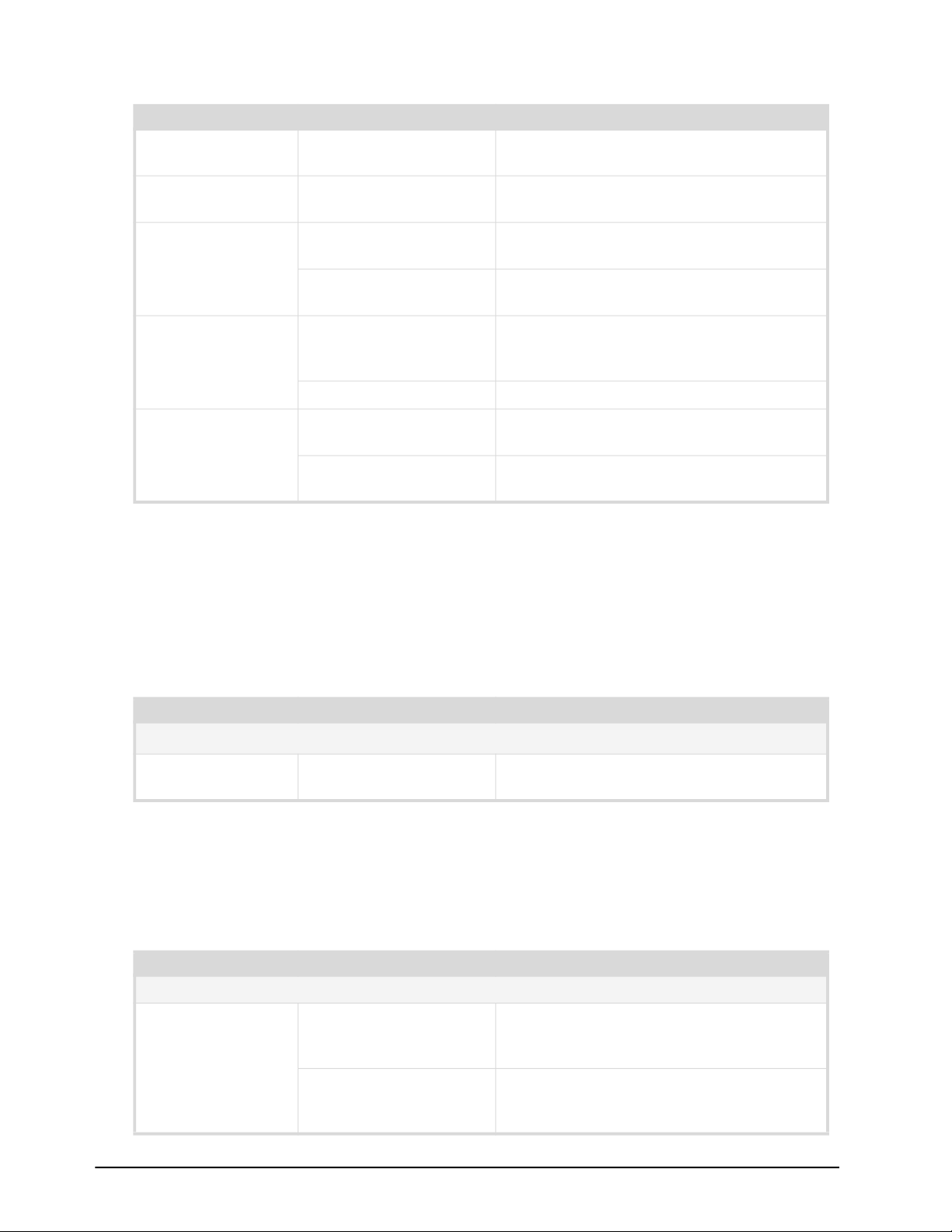
Item Parameters Description
Word Length
(read-only)
Table 13 Input Status — AES Status
#bit Reports the number of bits of audio
Sample Rate
#kHz Reports the sample rate of the AES input
(read-only)
Emphasis
(read-only)
Yes The incoming AES signal is indicating 50/15
or CCiTT J.17 emphasis
No The incoming AES signal is indicating no
emphasis or the emphasis is not indicated
Presence Alarm
c
Selected* The Input Status > AES Status tab reports
when the specified AES input is not
detected
Cleared Disables the alarm.
Async Alarm
c
Selected The AES source is either asynchronous to
the input video, or is not a 48kHz rate
Cleared Disables the alarm. The AES input is not
monitored.
a. The fields on this tab are disabled if the AES signal is configured as an output.
b. If the Sample Rate Conversion is enabled, an Async AES signal is processed to be PCM and indicated as such.
c. This option is disabled if the AES signal is configured for loopback.
Analog Status
Table 13 summarizes the read-only fields displayed in the Analog Status tab. This tab displays when
using an AMX-8952-C.
Table 14 Input Status — Analog Status
Item Parameters Description
Analog # Input
Channel # (dB)
(read-only)
a. The fields on this tab are disabled if the analog signal is configured as an output.
a
# Reports the audio gain applied to the
channel
Config Tab
Table 15 summarizes the menus displayed in the Config tab.
Table 15 Config Tab
Item Parameters Description
Video Input
Primary Video
Source
Input from SDI IN* Assigns SDI IN (BNC 1) as the primary input
signal when the Loss of Input Failover mode
is enabled
Input from SDI BI-DIR Assigns SDI BI-DIR (BNC 3) as the primary
input signal when Loss of Input Failover
mode is enabled
80 • DashBoard Menus AMX-8952 Series User Guide (v5.0)
Page 81

Item Parameters Description
Backup Video
Input from SDI Assigns SDI IN (BNC 1) as the backup input
Source
Input from SDI Bi-DIR* Assigns SDI BI-DIR (BNC 3) as the backup
Configure Loss of Input
Table 15 Config Tab
signal when the Loss of Input Failover mode
is enabled
input signal when the Loss of Input Failover
mode is enabled
Loss of Input
Failover
ON • Enables the feature where the SDI IN 1
video signal (as defined by the Input Video
Source menu) is the primary source and
the SDI BI-DIR source is defined as the
Backup Video Source (by default).
• If the primary source is lost, the card
automatically switches to the backup
source; the card stays on the backup
source until the user manually switches
the signal back to the primary source.
OFF* Disables this feature
Force Failover Normal* The card automatically switches input video
sources when a loss of input signal is
detected
Forced The user has manually switched between
the input video sources by clicking this
button
Output Video on
Loss of Input
Matte A solid (single) color pattern will replace all
of the output picture (but not the HANC and
VANC) during a loss of input video. The
color is specified by the Matte Color menu.
Test Pattern A SMPTE bars test pattern will replace all of
the output picture (but not the HANC and
VANC) during a loss of input video
Freeze Sets the output to freeze the last valid
frame of video if there is a loss of input
Video Output
Output Video
Source
Video In The video output of the card is a copy of the
SDI input signal. The Output Format menu
is now read-only.
Test Pattern Specifies that a SMPTE bars test pattern will
replace all of the output picture (but not the
HANC and VANC)
Matte The video output of the card is a matte
pattern as determined by the Matte Color
menu value
AMX-8952 Series User Guide (v5.0) DashBoard Menus • 81
Page 82

Table 15 Config Tab
Item Parameters Description
Output Format # Specifies the video format for the output
signal
# (read-only) The Output Video Source is set to Video In.
The output format is automatically set to
match the last detected video input signal.
Configure Outputs
Clip at Black Selected Enables the card to clip to SMPTE black on
all outputs
Cleared Super Black is passed
Clip at White Selected Enables the card to clip to SMPTE white on
all outputs
Cleared Super White is passed
Enable Bouncing
Box
Matte Color # Specifies the color the Matte Pattern will
Frame Sync and Output Timing
Frame Sync Status Licensed (Green) The AMX-8952-FS-LICENSE is installed.
Mode Frame sync ON* Enables this feature. Refer to “Frame Sync
Configure Output Delay
Horizontal Delay
(percent of line)
Selected An overlay in the shape of a box, filled with
the specified custom color, moves across
the screen in a pre-determined pattern
Cleared Disables this feature
display. A matte pattern can be assigned to
the Output Video on Loss of Input and/or to
as the default Output Video signal. The
default is White.
Unlicensed (Gray) The AMX-8952-FS-LICENSE is not installed.
Refer to “Installing a License Key”.
Off (Gray) The Mode is set to Frame sync OFF
Configuration” for details.
Frame sync OFF Disables this feature
# Adjusts the horizontal delay with respect to
the reference. This slider is read-only if the
Mode is set to Frame sync OFF.
Vertical Delay (lines) # Specifies the vertical delay with respect to
the reference. This slider is read-only if the
Mode is set to Frame sync OFF.
Frame Delay
(frames)
# Specifies the number of frames of delay
with respect to the reference. The default is
1 frame. This slider is read-only if the Mode
is set to Frame sync OFF.
Audio Tab
The Audio tab provides options for configuring the audio signals for the AMX-8952.
82 • DashBoard Menus AMX-8952 Series User Guide (v5.0)
Page 83
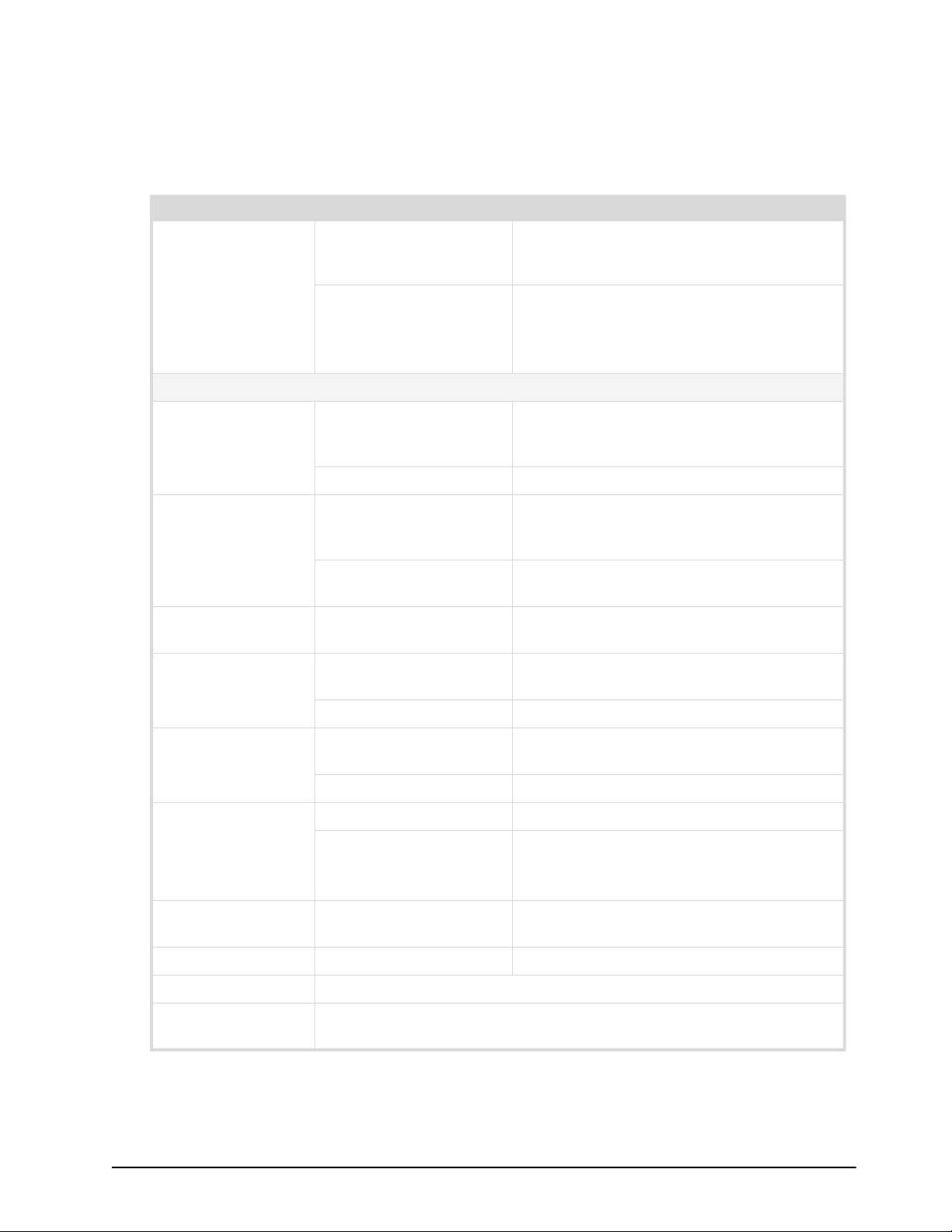
Embedded Tab
Table 16 summarizes the options displayed in the Embedded sub-tab. This tab displays for all
AMX-8952 series cards.
Table 16 AMX-8952 # Interface — Audio > Embedded Tab
Item Parameters Description
Sample Rate
Conversion
Ch #
Audio Source Group # Ch # Specifies the input for the specified channel
Mute Selected Mutes the input source for the specified
Selected Applies the SRC on the audio channels in
the video input before processed by the
Frame Sync
Cleared SRC is not applied to any of the audio
channels in the SDI input
Select this option when using non-PCM
audio data
that is inserted into the embedded pair (if
present)
#kHz Tone Embeds the selected test tone
channel that is inserted into the embedded
pair (if present)
Cleared The input source for the specified channel
is not muted
Gain (dB) # Adjusts the gain of the specified channel of
audio. Select 0 when using non-PCM audio.
Gain Lock Selected Locks the Ch Gain slider for the specified
channel pair
Cleared Unlocks the Ch Gain slider
Sum Selected Both channels will carry the average of the
two input channels ((A+B)/2)
Cleared Disables this feature
Invert Selected Inverts the audio signal of the specified pair
Cleared • Audio signal of the specified pair is not
inverted
• Use for non-PCM audio data
Total Delay (ms)
(read-only)
Delay Offset (ms) Adjusts the delay of the specified channel
Delay Lock Locks the Ch Delay slider for the specified channel pair
Reset Resets all Audio Output settings for the applicable audio pair to the
# Reports the total delay applied to the
specified channel
factory default values
AES Tab
Table 16 summarizes the options displayed in the AES sub-tab.
AMX-8952 Series User Guide (v5.0) DashBoard Menus • 83
Page 84

This tab only displays when using an AMX-8952-A or AMX-8952-B.
Table 17 AMX-8952 # Interface — Audio > AES Tab
Item Parameters Description
AES # - Channel #
Audio Source AES# Ch # Assigns the specified channel of the
specified AES signal
SDI Ch # Assigns the specified channel from the SDI
IN signal
#Hz Tone Assigns the specified test tone
Mute Selected Mutes the input source for the specified
channel
Cleared The input source for the specified channel
is not muted
Gain (dB) # • Adjusts the gain of the specified channel
of audio
• Select 0 when using non-PCM audio
Gain Lock Selected Locks the Ch Gain slider for the specified
pair
Cleared Unlocks the Ch Gain slider
Sum Selected Both channels will carry the average of the
two input channels ((A+B)/2)
Cleared Disables this feature
Invert Selected Inverts the audio signal of the specified AES
pair
Cleared • Audio signal of the specified AES pair is
not inverted
• Use for non-PCM audio data
Total Delay (ms)
(read-only)
Delay Offset (ms) # Adjusts the delay of the specified AES
Delay Lock Locks the Ch Delay slider for the specified AES channel pair
Reset Resets all settings for the applicable AES pair to the factory defaults
# Reports the total delay applied to the
specified AES channel
channel
Analog Tab
Table 16 summarizes the options displayed in the Analog sub-tab.
This tab only displays when using an AMX-8952-C.
84 • DashBoard Menus AMX-8952 Series User Guide (v5.0)
Page 85

Table 18 AMX-8952 # Interface — Audio > Analog Tab
Item Parameters Description
Analog # - Channel #
Audio Source Analog # Ch # Assigns the specified channel of the
specified analog signal
SDI Ch # Assigns the specified channel from the SDI
IN signal
#Hz Tone Assigns the specified test tone
Mute Selected Mutes the input source for the specified
channel
Cleared The input source for the specified channel
is not muted
Gain (dB) # • Adjusts the gain of the specified channel
of audio
• Select 0 when using non-PCM audio
Gain Lock Selected Locks the Ch Gain slider for the specified
pair
Cleared Unlocks the Ch Gain slider
Sum Selected Both channels will carry the average of the
two input channels ((A+B)/2)
Cleared Disables this feature
Invert Selected Inverts the audio signal of the specified
analog channel pair
Cleared • Audio signal of the specified pair is not
inverted
• Use for non-PCM audio data
Delay Offset (ms) # Adjusts the delay of the specified channel
Delay Lock Locks the Ch Delay slider for the specified channel pair
Reset Resets all settings for the applicable pair to the factory defaults
ANC Tab
Table 19 summarizes the ANC options available in DashBoard.
AMX-8952 Series User Guide (v5.0) DashBoard Menus • 85
Page 86

Item Parameters Description
ANC Frame Delay
(read-only)
Table 19 ANC Tab
# • The frame delay is always relative to the
next output frame.
• The ANC frame sync may operate with
different input and output frame rates.
• The output is at a fixed rate as defined by
the Output Video mode.
• When the output rate is lower than the
input rate, then there is the potential for
multiple inputs fields to be copied into the
same output field.
• When the output rate is higher than the
input rate, then there will be some output
fields with no ANC data.
Packet Name
(read-only)
Action Delete Card deletes the packet from the output
Insertion Line Switch Line + # Selects a line to insert the specified ANC
# Indicates the ancillary data type
Pass • The card receives and re-inserts the
specified packet type into the specified
line without modifying the packet
contents
• This option is only applicable to packets
that the card is not currently able to
process
Process Card receives the ANC packet, processes it,
and re-inserts it
packet on.
Note that if more than one packet is to be
inserted in the same line, the packet with
the lowest insertion order number will be
inserted first.
Process Card receives the Closed Captioning CC-708
packet, processes it, and inserts a new
packet into the specific line
Insertion Order # Defines the hierarchy of the packets
insertion.
Note that the lower the number, the higher
priority the packet is given.
GPI/Tally Tab
Table 20 summarizes the options displayed in the GPI/Tally tab.
Table 20 GPI/Tally Tab
Item Parameters Description
GPI/Tally #
86 • DashBoard Menus AMX-8952 Series User Guide (v5.0)
Page 87

Table 20 GPI/Tally Tab
Item Parameters Description
Function None* The specified GPIO port is not configured
and the port state has no effect. The
Trigger/Tally Type setting is ignored.
Tally Failover Active The port will trigger a switch between the
input video sources
General Output The port will trigger events on an external
GPI I/O device from the card
GPI Force Failover The port will trigger a switch between the
input video sources
General Input When the card receives a trigger on the
selected GPI input, it runs the events that
have been assigned to the GPI input.
Trigger/Tally Type Falling* If configured for Falling Edge, the selected
function is executed when the GPI input
signal transitions from High to Low
Rising If configured for Rising Edge, the selected
function is executed when the GPI input
signal transitions from Low to High
High If configured for Active High, the selected
function is executed when the GPI input
signal is driven High
Low If configured for Active Low, the selected
function is executed when the GPI input
signal is driven Low
Current State
(read-only)
Output Pulse Width
(frames)
High Reports the state of the specified GPIO port
Low
# Specifies the number of frames between
the rising and falling edges of the output
Manual Override Selected The user will trigger a switch in states
Cleared The port will trigger a switch in states
Level High The output toggles from the base low level
to the high level. The output signal remains
at this level until reset.
Low The output level toggles from the base high
level to the low level. The output signal
remains at this level until reset.
AMX-8952 Series User Guide (v5.0) DashBoard Menus • 87
Page 88

88 • DashBoard Menus AMX-8952 Series User Guide (v5.0)
Page 89

Technical Specifications
This chapter provides technical information for AMX-8952.
Specifications are subject to change without notice.
Supported Video Formats
Table 21 Technical Specifications — Supported Video Formats
Video Format
HD Formats
720p 50Hz
720p 59.94Hz
1080i 50Hz
1080i 59.94Hz
1080pSF 23.98Hz
1080pSF 24Hz
1080p 23.98Hz
1080p 24Hz
1080p 25Hz
1080p 29.97Hz
1080p 30Hz
1080p 50Hz
1080p 59.94Hz
1080p 60Hz
UHD Formats
2160p 23.98Hz
2160p 24Hz
2160p 25Hz
2160p 29.97Hz
2160p 30Hz
2160p 50Hz
2160p 59.94Hz
a.Supported on the input only.
b.Requires the AMX-8952-UHD-LICENSE.
a
b
AMX-8952 Series User Guide (v5.0) Technical Specifications • 89
Page 90

SDI Inputs Specifications
Table 22 Technical Specifications — SDI Inputs
Item Specifications
Number of Inputs 1 dedicated
Connector Type HD-BNC
Standards Accommodated 1.485Gbps Component, SMPTE 292M
Impedance 75ohm
Return Loss >15dB to 1.5GHz
1 bi-directional
2.97Gbps Component, SMPTE 424M
5.94Gbps Component, SMPTE ST-2081
11.88Gbps Component, SMPTE ST-2082
>10dB to 3GHz
>7dB to 6GHz
>4dB to 12GHz
Equalization (Belden 1694A
cable)
SDI Outputs Specifications
Table 23 Technical Specifications — SDI Outputs
Item Specifications
Number of Outputs 1 dedicated
Connector Type HD-BNC
Impedance 75ohm
Return Loss >15dB to 1.5GHz
>150m (492ft) @ 1.485Gbps
>120m (394ft) @ 2.97Gbps
@ 5.94Gbps
>50m (190ft) @ 11.88Gbps
1 bi-directional
>10dB to 3GHz
>7dB to 6GHz
>4dB to 12GHz
Signal Level 800mV ±10%
DC Offset 0V ±50mV
Rise and Fall Time (20-80%) 1.485Gbps: <270ps, <100ps difference
2.97Gbps: <135ps, <50ps difference
5.94Gbps:
11.88Gbps: <45ps, <18ps difference
90 • Technical Specifications AMX-8952 Series User Guide (v5.0)
Page 91
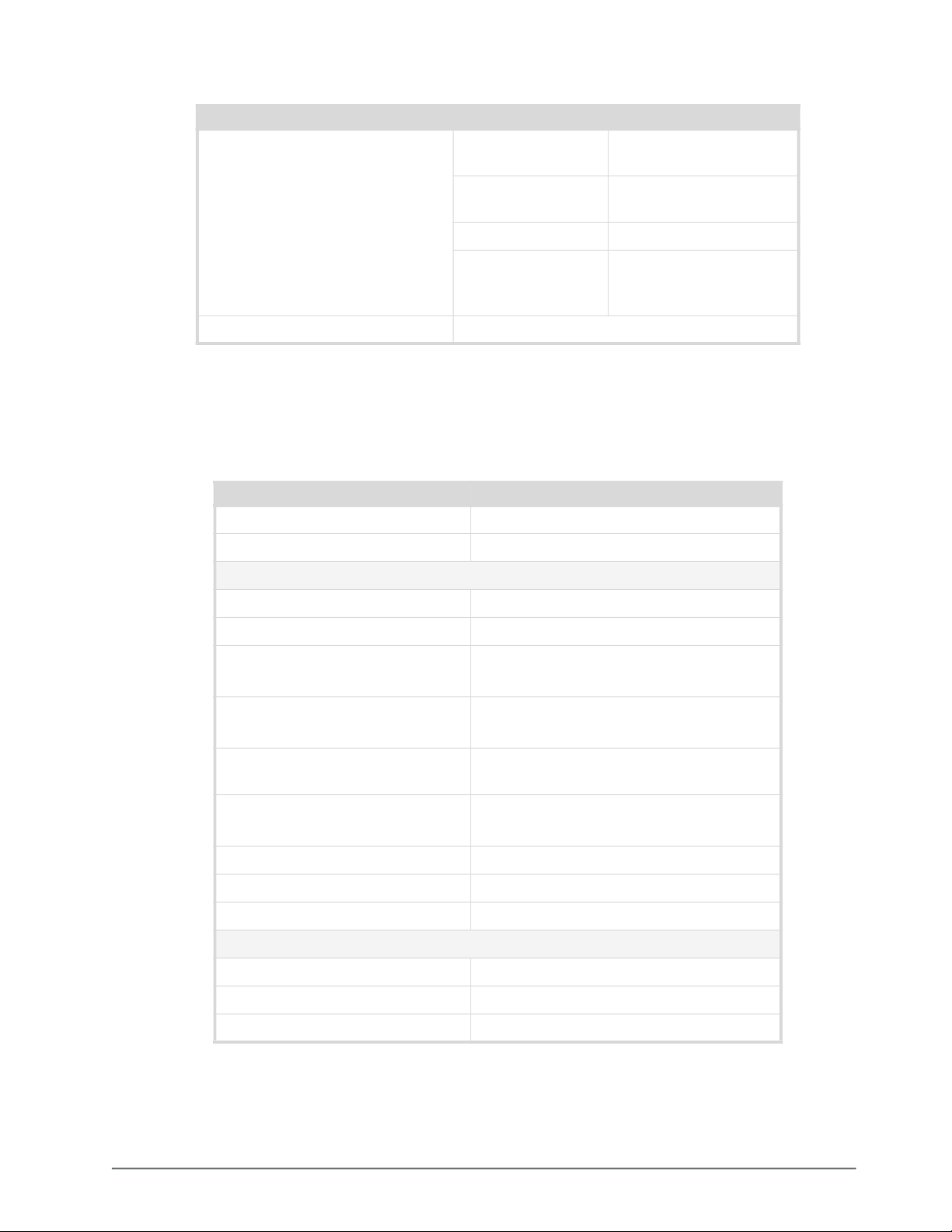
Table 23 Technical Specifications — SDI Outputs
Item Specifications
Jitter 1.485Gbps: <1.0UI 10Hz-100kHz,
Overshoot <10% (11.88Gpbs: <15%)
AES Specifications
AMX-8952-A
Standards Accommodated AES-3id-2001, AES3
<0.2UI above 100kHz
2.97Gbps: <1.0UI 10Hz-100kHz,
<0.3UI above 100kHz
5.94Gbps:
11.88Gbps: <2.0UI 10Hz-100kHz,
<0.3UI above 100kHz,
band limit @1188MHz
Table 24 AES Specifications — AMX-8952-A
Item Specifications
Connector Type HD-BNC
Inputs
Impedance 75ohm
Minimum Input 50mV p-p
Maximum Input 2.5V p-p @ 48kHz
1.5V p-p @ 96kHz
Minimum Audio Delay SRC enabled: 1.35mS
SRC disabled: 0.37mS
Sampling Rate 48kHz compliant with AES-3id or any
rate from 32kHz to 96kHz with SRC on
Equalization up to 800m (2,400ft) @ 48kHz
up to 500m (1,500ft) @ 96kHz
Output Amplitude 4Vp-p
Rise and Fall Times 30ns
Jitter 4.5mUI
Outputs
Impedance 75ohm
Output Level 1V p-p
Sampling Rate 48kHz
AMX-8952 Series User Guide (v5.0) Technical Specifications • 91
Page 92

AMX-8952-B
Standards Accommodated AES-3id-2001, AES3
Connector Type 3-pin WECO™
Inputs
Impedance 110ohm
Minimum Input 100mV
Maximum Input 10Vp-p
Minimum Audio Delay 2.3ms (SRC enabled)
Sampling Rate SRC enabled: up to 96KHz
Equalization >450m of Belden 1492 cable
Return Loss >26dB 100KHz to 6MHz
Output Amplitude 4Vp-p
Rise and Fall Times 30ns
Jitter 4.5mUI
Table 25 AES Specifications — AMX-8952-B
Item Specifications
SRC disabled: 1.0ms
Outputs
Impedance 110ohm
Minimum Audio Delay 2.3ms (SRC enabled)
Sampling Rate up to 96KHz
Equalization >450m of Belden 1492 cable
Return Loss >26dB 100KHz to 6MHz
Output Amplitude 4Vp-p
Rise and Fall Times 30ns
Jitter 4.5mUI
Analog Specifications
AMX-8952-C
Table 26 Analog Specifications — AMX-8952-C
Item Specifications
Connector Type 3-pin WECO™
Inputs
Impedance >12kohm
Maximum Input Level +24dBu
Input Level Adjustment ±20dBu
Frequency Response ±0.10dB 20Hz to 20kHz @ Fs = 48kHz
92 • Technical Specifications AMX-8952 Series User Guide (v5.0)
Page 93
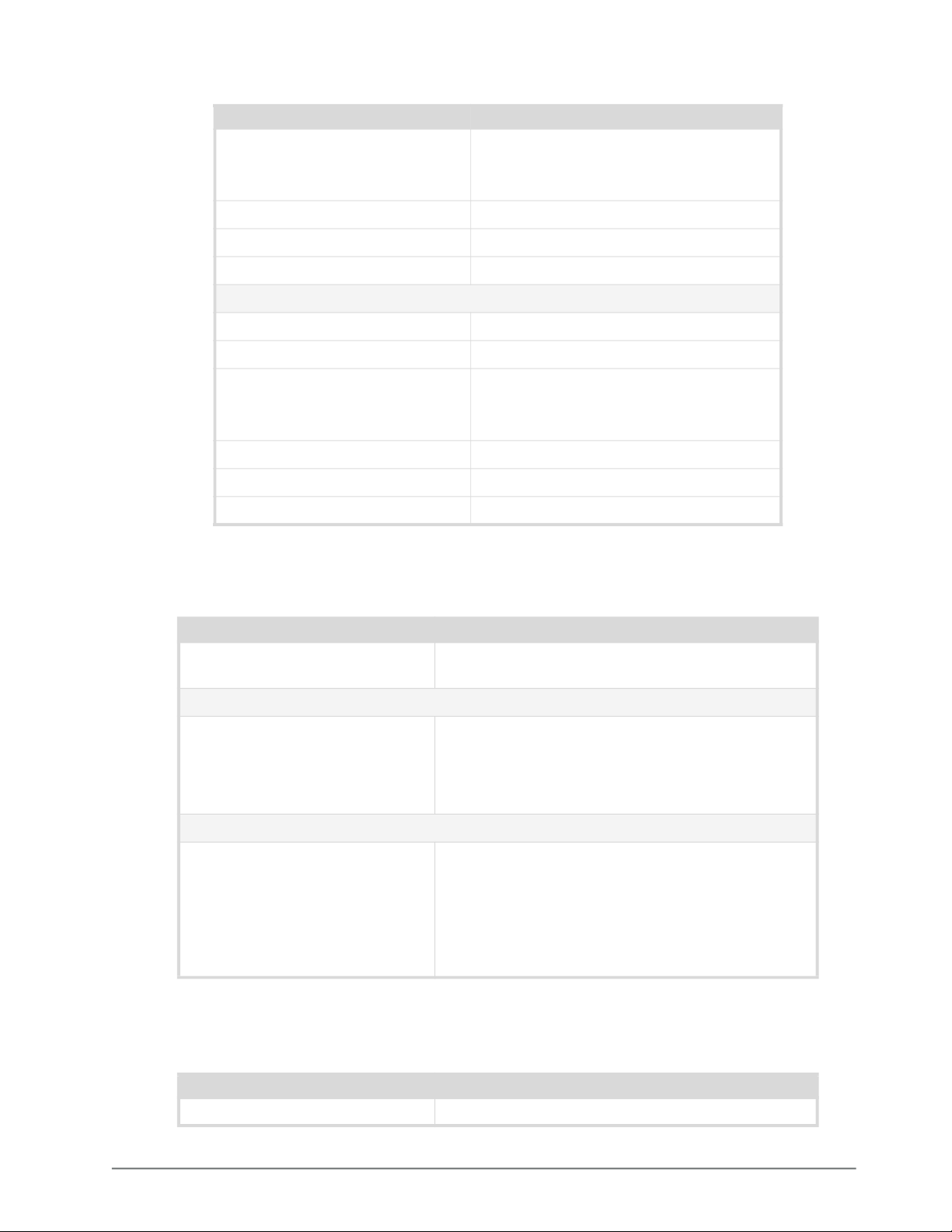
Table 26 Analog Specifications — AMX-8952-C
Item Specifications
Signal to Noise Ratio
THD < -90dB (0.003%) @ 1kHz
Amplitude Linearity < 0.6dB @ -100dBFS
Crosstalk -95dB
Outputs
Maximum Output Level +24dBu
Frequency Response ±0.10dB 20Hz to 20kHz @ Fs = 48kHz
-100dB
-104dB ‘A’ weighted
-101dB CCIR-2K
Signal to Noise Ratio
THD < -90dB (0.003%) @ 1kHz
Amplitude Linearity < 0.5dB @ -100dBFS
Crosstalk <-98dB (20Hz to 20kHz)
-103dB
-108dB ‘A’ weighted
-105dB CCIR-2K
GPIO
Table 27 Technical Specifications — GPIO
Item Specifications
Absolute Maximum Voltage at
Connector Pins
GPI
Input • 4.7K ohm resistor pull-up to 5V for High
Tally
1.0V to +6.0V to prevent damage
• GND contact closure (or external logic) for Low
• High In is >= 2.5V
• Low In is <= 0.5V
Output • Pulled to 5V with 4k7 ohm resistor for High
• Driven to ground or Low through 30ohms
• Maximum sink current 50mA to drive an external
relay
• To drive a logic gate input, sink current needs to
be below 10mA (0.3V at pin)
Environment
Table 28 Technical Specifications — Environment
Item Specifications
Maximum Ambient Temperature 40°C (104°F)
AMX-8952 Series User Guide (v5.0) Technical Specifications • 93
Page 94

Power
Maximum Power Consumption AMX-8952-A,
Table 29 Technical Specifications — Power
Item Specifications
20W
AMX-8952-B
AMX-8952-C 25W
94 • Technical Specifications AMX-8952 Series User Guide (v5.0)
Page 95

Software Licenses
This chapter provides third-party software license information for your AMX-8952. This product
includes multiple software components which are individually licensed under one or more of the
following licenses included in this chapter.
BSD
Copyright (c) 1991,1993, The Regents of the University of California. All rights reserved.
This code is derived from software contributed to Berkeley by Kenneth Almquist.
Redistribution and use in source and binary forms, with or without modification, are permitted provided that the following conditions are met:
1. Redistributions of source code must retain the above copyright notice, this list of conditions and the following disclaimer.
2. Redistributions in binary form must reproduce the above copyright notice, this list of conditions and the following disclaimer in the documentation and/or other
materials provided with the distribution.
3. <BSD Advertising Clause omitted per the July 22, 1999 licensing change ftp://ftp.cs.berkeley.edu/pub/4bsd/README.Impt.License.Change> California, Berkeley and its contributors.
4. Neither the name of the University nor the names of its contributors may be used to endorse or promote products derived from this software without specific prior
written permission.
THIS SOFTWARE IS PROVIDED BY THE REGENTS AND CONTRIBUTORS ``AS IS'' AND ANY EXPRESS OR IMPLIED WARRANTIES, INCLUDING,
BUT NOT LIMITED TO, THE IMPLIED WARRANTIES OF MERCHANTABILITY AND FITNESS FOR A PARTICULAR PURPOSE ARE DISCLAIMED. IN
NO EVENT SHALL THE REGENTS OR CONTRIBUTORS BE LIABLE FOR ANY DIRECT, INDIRECT, INCIDENTAL, SPECIAL, EXEMPLARY, OR CONSEQUENTIAL DAMAGES (INCLUDING, BUT NOT LIMITED TO, PROCUREMENT OF SUBSTITUTE GOODS OR SERVICES; LOSS OF USE, DATA, OR
PROFITS; OR BUSINESS INTERRUPTION) HOWEVER CAUSED AND ON ANY THEORY OF LIABILITY, WHETHER IN CONTRACT, STRICT LIABILITY, OR TORT (INCLUDING NEGLIGENCE OR OTHERWISE) ARISING IN ANY WAY OUT OF THE USE OF THIS SOFTWARE, EVEN IF ADVISED OF
THE POSSIBILITY OF SUCH DAMAGE.
Dual GPL
Portions of this software are copyright (C) 1996-2002 The FreeType Project (www.freetype.org). All rights reserved.
This project is also covered under the GPL v2.
GPL
GNU GENERAL PUBLIC LICENSE
Copyright (C) 2007 Free Software Foundation, Inc. <http://fsf.org/>
The GNU General Public License is a free, copyleft license for software and other kinds of works.
The licenses for most software and other practical works are designed to take away your freedom to share and change the works. By contrast, the GNU General Public License is intended to guarantee your freedom to share and change all versions of a program--to make sure it remains free software for all its users. We, the Free
Software Foundation, use the GNU General Public License for most of our software; it applies also to any other work released this way by its authors. You can apply
it to your programs, too.
When we speak of free software, we are referring to freedom, not price. Our General Public Licenses are designed to make sure that you have the freedom to distribute copies of free software (and charge for them if you wish), that you receive source code or can get it if you want it, that you can change the software or use pieces
of it in new free programs, and that you know you can do these things.
To protect your rights, we need to prevent others from denying you these rights or asking you to surrender the rights. Therefore, you have certain responsibilities if
you distribute copies of the software, or if you modify it: responsibilities to respect the freedom of others.
For example, if you distribute copies of such a program, whether gratis or for a fee, you must pass on to the recipients the same freedoms that you received. You must
make sure that they, too, receive or can get the source code. And you must show them these terms so they know their rights.
Developers that use the GNU GPL protect your rights with two steps: (1) assert copyright on the software, and (2) offer you this License giving you legal permission
to copy, distribute and/or modify it.
For the developers' and authors' protection, the GPL clearly explains that there is no warranty for this free software. For both users' and authors' sake, the GPL
requires that modified versions be marked as changed, so that their problems will not be attributed erroneously to authors of previous versions.
Some devices are designed to deny users access to install or run modified versions of the software inside them, although the manufacturer can do so. This is fundamentally incompatible with the aim of protecting users' freedom to change the software. The systematic pattern of such abuse occurs in the area of products for individuals to use, which is precisely where it is most unacceptable. Therefore, we have designed this version of the GPL to prohibit the practice for those products. If
Version 3, 29 June 2007
Preamble
AMX-8952 Series User Guide (v5.0) Software Licenses • 95
Page 96

such problems arise substantially in other domains, we stand ready to extend this provision to those domains in future versions of the GPL, as needed to protect the
freedom of users.
Finally, every program is threatened constantly by software patents. States should not allow patents to restrict development and use of software on general-purpose
computers, but in those that do, we wish to avoid the special danger that patents applied to a free program could make it effectively proprietary. To prevent this, the
GPL assures that patents cannot be used to render the program non-free.
The precise terms and conditions for copying, distribution and modification follow.
TERMS AND CONDITIONS
0. Definitions.
"This License" refers to version 3 of the GNU General Public License.
"Copyright" also means copyright-like laws that apply to other kinds of works, such as semiconductor masks.
"The Program" refers to any copyrightable work licensed under this License. Each licensee is addressed as "you". "Licensees" and "recipients" may be individuals or
organizations.
To "modify" a work means to copy from or adapt all or part of the work in a fashion requiring copyright permission, other than the making of an exact copy. The
resulting work is called a "modified version" of the earlier work or a work "based on" the earlier work.
A "covered work" means either the unmodified Program or a work based on the Program.
To "propagate" a work means to do anything with it that, without permission, would make you directly or secondarily liable for infringement under applicable copyright law, except executing it on a computer or modifying a private copy. Propagation includes copying, distribution (with or without modification), making available
to the public, and in some countries other activities as well.
To "convey" a work means any kind of propagation that enables other parties to make or receive copies. Mere interaction with a user through a computer network,
with no transfer of a copy, is not conveying.
An interactive user interface displays "Appropriate Legal Notices" to the extent that it includes a convenient and prominently visible feature that (1) displays an
appropriate copyright notice, and (2) tells the user that there is no warranty for the work (except to the extent that warranties are provided), that licensees may convey
the work under this License, and how to view a copy of this License. If the interface presents a list of user commands or options, such as a menu, a prominent item in
the list meets this criterion.
1. Source Code.
The "source code" for a work means the preferred form of the work for making modifications to it. "Object code" means any non-source form of a work.
A "Standard Interface" means an interface that either is an official standard defined by a recognized standards body, or, in the case of interfaces specified for a particular programming language, one that is widely used among developers working in that language.
The "System Libraries" of an executable work include anything, other than the work as a whole, that (a) is included in the normal form of packaging a Major Component, but which is not part of that Major Component, and (b) serves only to enable use of the work with that Major Component, or to implement a Standard Interface
for which an implementation is available to the public in source code form. A "Major Component", in this context, means a major essential component (kernel, window system, and so on) of the specific operating system (if any) on which the executable work runs, or a compiler used to produce the work, or an object code interpreter used to run it.
The "Corresponding Source" for a work in object code form means all the source code needed to generate, install, and (for an executable work) run the object code
and to modify the work, including scripts to control those activities. However, it does not include the work's System Libraries, or general-purpose tools or generally
available free programs which are used unmodified in performing those activities but which are not part of the work. For example, Corresponding Source includes
interface definition files associated with source files for the work, and the source code for shared libraries and dynamically linked subprograms that the work is specifically designed to require, such as by intimate data communication or control flow between those subprograms and other parts of the work.
The Corresponding Source need not include anything that users can regenerate automatically from other parts of the Corresponding Source.
The Corresponding Source for a work in source code form is that same work.
2. Basic Permissions.
All rights granted under this License are granted for the term of copyright on the Program, and are irrevocable provided the stated conditions are met. This License
explicitly affirms your unlimited permission to run the unmodified Program. The output from running a covered work is covered by this License only if the output,
given its content, constitutes a covered work. This License acknowledges your rights of fair use or other equivalent, as provided by copyright law.
You may make, run and propagate covered works that you do not convey, without conditions so long as your license otherwise remains in force. You may convey
covered works to others for the sole purpose of having them make modifications exclusively for you, or provide you with facilities for running those works, provided
that you comply with the terms of this License in conveying all material for which you do not control copyright. Those thus making or running the covered works for
you must do so exclusively on your behalf, under your direction and control, on terms that prohibit them from making any copies of your copyrighted material outside their relationship with you.
Conveying under any other circumstances is permitted solely under the conditions stated below. Sublicensing is not allowed; section 10 makes it unnecessary.
3. Protecting Users' Legal Rights From Anti-Circumvention Law.
No covered work shall be deemed part of an effective technological measure under any applicable law fulfilling obligations under article 11 of the WIPO copyright
treaty adopted on 20 December 1996, or similar laws prohibiting or restricting circumvention of such measures.
When you convey a covered work, you waive any legal power to forbid circumvention of technological measures to the extent such circumvention is effected by
exercising rights under this License with respect to the covered work, and you disclaim any intention to limit operation or modification of the work as a means of
enforcing, against the work's users, your or third parties' legal rights to forbid circumvention of technological measures.
4. Conveying Verbatim Copies.
You may convey verbatim copies of the Program's source code as you receive it, in any medium, provided that you conspicuously and appropriately publish on each
copy an appropriate copyright notice; keep intact all notices stating that this License and any non-permissive terms added in accord with section 7 apply to the code;
keep intact all notices of the absence of any warranty; and give all recipients a copy of this License along with the Program.
96 • Software Licenses AMX-8952 Series User Guide (v5.0)
Page 97

You may charge any price or no price for each copy that you convey, and you may offer support or warranty protection for a fee.
5. Conveying Modified Source Versions.
You may convey a work based on the Program, or the modifications to produce it from the Program, in the form of source code under the terms of section 4, provided
that you also meet all of these conditions:
a. The work must carry prominent notices stating that you modified it, and giving a relevant date.
b. The work must carry prominent notices stating that it is released under this License and any conditions added under section 7. This requirement modifies
the requirement in section 4 to "keep intact all notices".
c. You must license the entire work, as a whole, under this License to anyone who comes into possession of a copy. This License will therefore apply, along
with any applicable section 7 additional terms, to the whole of the work, and all its parts, regardless of how they are packaged. This License gives no
permission to license the work in any other way, but it does not invalidate such permission if you have separately received it.
d. If the work has interactive user interfaces, each must display Appropriate Legal Notices; however, if the Program has interactive interfaces that do not
display Appropriate Legal Notices, your work need not make them do so.
A compilation of a covered work with other separate and independent works, which are not by their nature extensions of the covered work, and which are not combined with it such as to form a larger program, in or on a volume of a storage or distribution medium, is called an "aggregate" if the compilation and its resulting
copyright are not used to limit the access or legal rights of the compilation's users beyond what the individual works permit. Inclusion of a covered work in an aggregate does not cause this License to apply to the other parts of the aggregate.
6. Conveying Non-Source Forms.
You may convey a covered work in object code form under the terms of sections 4 and 5, provided that you also convey the machine-readable Corresponding Source
under the terms of this License, in one of these ways:
a. Convey the object code in, or embodied in, a physical product (including a physical distribution medium), accompanied by the Corresponding Source
fixed on a durable physical medium customarily used for software interchange.
b. Convey the object code in, or embodied in, a physical product (including a physical distribution medium), accompanied by a written offer, valid for at
least three years and valid for as long as you offer spare parts or customer support for that product model, to give anyone who possesses the object code
either (1) a copy of the Corresponding Source for all the software in the product that is covered by this License, on a durable physical medium customarily
used for software interchange, for a price no more than your reasonable cost of physically performing this conveying of source, or (2) access to copy the
Corresponding Source from a network server at no charge.
c. c) Convey individual copies of the object code with a copy of the written offer to provide the Corresponding Source. This alternative is allowed only
occasionally and noncommercially, and only if you received the object code with such an offer, in accord with subsection 6b.
d. d) Convey the object code by offering access from a designated place (gratis or for a charge), and offer equivalent access to the Corresponding Source in
the same way through the same place at no further charge. You need not require recipients to copy the Corresponding Source along with the object code.
If the place to copy the object code is a network server, the Corresponding Source may be on a different server (operated by you or a third party) that
supports equivalent copying facilities, provided you maintain clear directions next to the object code saying where to find the Corresponding Source.
Regardless of what server hosts the Corresponding Source, you remain obligated to ensure that it is available for as long as needed to satisfy these
requirements.
e. e) Convey the object code using peer-to-peer transmission, provided you inform other peers where the object code and Corresponding Source of the work
are being offered to the general public at no charge under subsection 6d.
A separable portion of the object code, whose source code is excluded from the Corresponding Source as a System Library, need not be included in conveying the
object code work.
A "User Product" is either (1) a "consumer product", which means any tangible personal property which is normally used for personal, family, or household purposes,
or (2) anything designed or sold for incorporation into a dwelling. In determining whether a product is a consumer product, doubtful cases shall be resolved in favor
of coverage. For a particular product received by a particular user, "normally used" refers to a typical or common use of that class of product, regardless of the status
of the particular user or of the way in which the particular user actually uses, or expects or is expected to use, the product. A product is a consumer product regardless
of whether the product has substantial commercial, industrial or non-consumer uses, unless such uses represent the only significant mode of use of the product.
"Installation Information" for a User Product means any methods, procedures, authorization keys, or other information required to install and execute modified versions of a covered work in that User Product from a modified version of its Corresponding Source. The information must suffice to ensure that the continued functioning of the modified object code is in no case prevented or interfered with solely because modification has been made.
If you convey an object code work under this section in, or with, or specifically for use in, a User Product, and the conveying occurs as part of a transaction in which
the right of possession and use of the User Product is transferred to the recipient in perpetuity or for a fixed term (regardless of how the transaction is characterized),
the Corresponding Source conveyed under this section must be accompanied by the Installation Information. But this requirement does not apply if neither you nor
any third party retains the ability to install modified object code on the User Product (for example, the work has been installed in ROM).
The requirement to provide Installation Information does not include a requirement to continue to provide support service, warranty, or updates for a work that has
been modified or installed by the recipient, or for the User Product in which it has been modified or installed. Access to a network may be denied when the modification itself materially and adversely affects the operation of the network or violates the rules and protocols for communication across the network.
Corresponding Source conveyed, and Installation Information provided, in accord with this section must be in a format that is publicly documented (and with an
implementation available to the public in source code form), and must require no special password or key for unpacking, reading or copying.
7. Additional Terms.
"Additional permissions" are terms that supplement the terms of this License by making exceptions from one or more of its conditions. Additional permissions that
are applicable to the entire Program shall be treated as though they were included in this License, to the extent that they are valid under applicable law. If additional
permissions apply only to part of the Program, that part may be used separately under those permissions, but the entire Program remains governed by this License
without regard to the additional permissions.
When you convey a copy of a covered work, you may at your option remove any additional permissions from that copy, or from any part of it. (Additional permissions may be written to require their own removal in certain cases when you modify the work.) You may place additional permissions on material, added by you to a
covered work, for which you have or can give appropriate copyright permission.
Notwithstanding any other provision of this License, for material you add to a covered work, you may (if authorized by the copyright holders of that material) supplement the terms of this License with terms:
a. Disclaiming warranty or limiting liability differently from the terms of sections 15 and 16 of this License; or
b. Requiring preservation of specified reasonable legal notices or author attributions in that material or in the Appropriate Legal Notices displayed by works
containing it; or
AMX-8952 Series User Guide (v5.0) Software Licenses • 97
Page 98

c. Prohibiting misrepresentation of the origin of that material, or requiring that modified versions of such material be marked in reasonable ways as different
from the original version; or
d. Limiting the use for publicity purposes of names of licensors or authors of the material; or
e. Declining to grant rights under trademark law for use of some trade names, trademarks, or service marks; or
f. Requiring indemnification of licensors and authors of that material by anyone who conveys the material (or modified versions of it) with contractual
assumptions of liability to the recipient, for any liability that these contractual assumptions directly impose on those licensors and authors.
All other non-permissive additional terms are considered "further restrictions" within the meaning of section 10. If the Program as you received it, or any part of it,
contains a notice stating that it is governed by this License along with a term that is a further restriction, you may remove that term. If a license document contains a
further restriction but permits relicensing or conveying under this License, you may add to a covered work material governed by the terms of that license document,
provided that the further restriction does not survive such relicensing or conveying.
If you add terms to a covered work in accord with this section, you must place, in the relevant source files, a statement of the additional terms that apply to those files,
or a notice indicating where to find the applicable terms.
Additional terms, permissive or non-permissive, may be stated in the form of a separately written license, or stated as exceptions; the above requirements apply either
way.
8. Termination.
You may not propagate or modify a covered work except as expressly provided under this License. Any attempt otherwise to propagate or modify it is void, and will
automatically terminate your rights under this License (including any patent licenses granted under the third paragraph of section 11).
However, if you cease all violation of this License, then your license from a particular copyright holder is reinstated (a) provisionally, unless and until the copyright
holder explicitly and finally terminates your license, and (b) permanently, if the copyright holder fails to notify you of the violation by some reasonable means prior
to 60 days after the cessation.
Moreover, your license from a particular copyright holder is reinstated permanently if the copyright holder notifies you of the violation by some reasonable means,
this is the first time you have received notice of violation of this License (for any work) from that copyright holder, and you cure the violation prior to 30 days after
your receipt of the notice.
Termination of your rights under this section does not terminate the licenses of parties who have received copies or rights from you under this License. If your rights
have been terminated and not permanently reinstated, you do not qualify to receive new licenses for the same material under section 10.
9. Acceptance Not Required for Having Copies.
You are not required to accept this License in order to receive or run a copy of the Program. Ancillary propagation of a covered work occurring solely as a consequence of using peer-to-peer transmission to receive a copy likewise does not require acceptance. However, nothing other than this License grants you permission to
propagate or modify any covered work. These actions infringe copyright if you do not accept this License. Therefore, by modifying or propagating a covered work,
you indicate your acceptance of this License to do so.
10. Automatic Licensing of Downstream Recipients.
Each time you convey a covered work, the recipient automatically receives a license from the original licensors, to run, modify and propagate that work, subject to
this License. You are not responsible for enforcing compliance by third parties with this License.
An "entity transaction" is a transaction transferring control of an organization, or substantially all assets of one, or subdividing an organization, or merging organizations. If propagation of a covered work results from an entity transaction, each party to that transaction who receives a copy of the work also receives whatever
licenses to the work the party's predecessor in interest had or could give under the previous paragraph, plus a right to possession of the Corresponding Source of the
work from the predecessor in interest, if the predecessor has it or can get it with reasonable efforts.
You may not impose any further restrictions on the exercise of the rights granted or affirmed under this License. For example, you may not impose a license fee, royalty, or other charge for exercise of rights granted under this License, and you may not initiate litigation (including a cross-claim or counterclaim in a lawsuit) alleging
that any patent claim is infringed by making, using, selling, offering for sale, or importing the Program or any portion of it.
11. Patents.
A "contributor" is a copyright holder who authorizes use under this License of the Program or a work on which the Program is based. The work thus licensed is called
the contributor's "contributor version".
A contributor's "essential patent claims" are all patent claims owned or controlled by the contributor, whether already acquired or hereafter acquired, that would be
infringed by some manner, permitted by this License, of making, using, or selling its contributor version, but do not include claims that would be infringed only as a
consequence of further modification of the contributor version. For purposes of this definition, "control" includes the right to grant patent sublicenses in a manner
consistent with the requirements of this License.
Each contributor grants you a non-exclusive, worldwide, royalty-free patent license under the contributor's essential patent claims, to make, use, sell, offer for sale,
import and otherwise run, modify and propagate the contents of its contributor version.
In the following three paragraphs, a "patent license" is any express agreement or commitment, however denominated, not to enforce a patent (such as an express permission to practice a patent or covenant not to sue for patent infringement). To "grant" such a patent license to a party means to make such an agreement or commitment not to enforce a patent against the party.
If you convey a covered work, knowingly relying on a patent license, and the Corresponding Source of the work is not available for anyone to copy, free of charge
and under the terms of this License, through a publicly available network server or other readily accessible means, then you must either (1) cause the Corresponding
Source to be so available, or (2) arrange to deprive yourself of the benefit of the patent license for this particular work, or (3) arrange, in a manner consistent with the
requirements of this License, to extend the patent license to downstream recipients. "Knowingly relying" means you have actual knowledge that, but for the patent
license, your conveying the covered work in a country, or your recipient's use of the covered work in a country, would infringe one or more identifiable patents in that
country that you have reason to believe are valid.
If, pursuant to or in connection with a single transaction or arrangement, you convey, or propagate by procuring conveyance of, a covered work, and grant a patent
license to some of the parties receiving the covered work authorizing them to use, propagate, modify or convey a specific copy of the covered work, then the patent
license you grant is automatically extended to all recipients of the covered work and works based on it.
A patent license is "discriminatory" if it does not include within the scope of its coverage, prohibits the exercise of, or is conditioned on the non-exercise of one or
more of the rights that are specifically granted under this License. You may not convey a covered work if you are a party to an arrangement with a third party that is
in the business of distributing software, under which you make payment to the third party based on the extent of your activity of conveying the work, and under which
the third party grants, to any of the parties who would receive the covered work from you, a discriminatory patent license (a) in connection with copies of the covered
98 • Software Licenses AMX-8952 Series User Guide (v5.0)
Page 99

work conveyed by you (or copies made from those copies), or (b) primarily for and in connection with specific products or compilations that contain the covered
work, unless you entered into that arrangement, or that patent license was granted, prior to 28 March 2007.
Nothing in this License shall be construed as excluding or limiting any implied license or other defenses to infringement that may otherwise be available to you under
applicable patent law.
12. No Surrender of Others' Freedom.
If conditions are imposed on you (whether by court order, agreement or otherwise) that contradict the conditions of this License, they do not excuse you from the conditions of this License. If you cannot convey a covered work so as to satisfy simultaneously your obligations under this License and any other pertinent obligations,
then as a consequence you may not convey it at all. For example, if you agree to terms that obligate you to collect a royalty for further conveying from those to whom
you convey the Program, the only way you could satisfy both those terms and this License would be to refrain entirely from conveying the Program.
13. Use with the GNU Affero General Public License.
Notwithstanding any other provision of this License, you have permission to link or combine any covered work with a work licensed under version 3 of the GNU
Affero General Public License into a single combined work, and to convey the resulting work. The terms of this License will continue to apply to the part which is the
covered work, but the special requirements of the GNU Affero General Public License, section 13, concerning interaction through a network will apply to the combination as such.
14. Revised Versions of this License.
The Free Software Foundation may publish revised and/or new versions of the GNU General Public License from time to time. Such new versions will be similar in
spirit to the present version, but may differ in detail to address new problems or concerns.
Each version is given a distinguishing version number. If the Program specifies that a certain numbered version of the GNU General Public License "or any later version" applies to it, you have the option of following the terms and conditions either of that numbered version or of any later version published by the Free Software
Foundation. If the Program does not specify a version number of the GNU General Public License, you may choose any version ever published by the Free Software
Foundation.
If the Program specifies that a proxy can decide which future versions of the GNU General Public License can be used, that proxy's public statement of acceptance of
a version permanently authorizes you to choose that version for the Program.
Later license versions may give you additional or different permissions. However, no additional obligations are imposed on any author or copyright holder as a result
of your choosing to follow a later version.
15. Disclaimer of Warranty.
THERE IS NO WARRANTY FOR THE PROGRAM, TO THE EXTENT PERMITTED BY APPLICABLE LAW. EXCEPT WHEN OTHERWISE STATED IN
WRITING THE COPYRIGHT HOLDERS AND/OR OTHER PARTIES PROVIDE THE PROGRAM "AS IS" WITHOUT WARRANTY OF ANY KIND, EITHER
EXPRESSED OR IMPLIED, INCLUDING, BUT NOT LIMITED TO, THE IMPLIED WARRANTIES OF MERCHANTABILITY AND FITNESS FOR A PARTICULAR PURPOSE. THE ENTIRE RISK AS TO THE QUALITY AND PERFORMANCE OF THE PROGRAM IS WITH YOU. SHOULD THE PROGRAM
PROVE DEFECTIVE, YOU ASSUME THE COST OF ALL NECESSARY SERVICING, REPAIR OR CORRECTION.
16. Limitation of Liability.
IN NO EVENT UNLESS REQUIRED BY APPLICABLE LAW OR AGREED TO IN WRITING WILL ANY COPYRIGHT HOLDER, OR ANY OTHER PARTY
WHO MODIFIES AND/OR CONVEYS THE PROGRAM AS PERMITTED ABOVE, BE LIABLE TO YOU FOR DAMAGES, INCLUDING ANY GENERAL,
SPECIAL, INCIDENTAL OR CONSEQUENTIAL DAMAGES ARISING OUT OF THE USE OR INABILITY TO USE THE PROGRAM (INCLUDING BUT
NOT LIMITED TO LOSS OF DATA OR DATA BEING RENDERED INACCURATE OR LOSSES SUSTAINED BY YOU OR THIRD PARTIES OR A FAILURE
OF THE PROGRAM TO OPERATE WITH ANY OTHER PROGRAMS), EVEN IF SUCH HOLDER OR OTHER PARTY HAS BEEN ADVISED OF THE POSSIBILITY OF SUCH DAMAGES.
17. Interpretation of Sections 15 and 16.
If the disclaimer of warranty and limitation of liability provided above cannot be given local legal effect according to their terms, reviewing courts shall apply local
law that most closely approximates an absolute waiver of all civil liability in connection with the Program, unless a warranty or assumption of liability accompanies
a copy of the Program in return for a fee.
AMX-8952 Series User Guide (v5.0) Software Licenses • 99
Page 100

LGPL
GNU LESSER GENERAL PUBLIC LICENSE
Copyright (C) 2007 Free Software Foundation, Inc. <http://fsf.org/>
Everyone is permitted to copy and distribute verbatim copies of this license document, but changing it is not allowed.
This version of the GNU Lesser General Public License incorporates the terms and conditions of version 3 of the GNU General Public License, supplemented by the
additional permissions listed below.
0. Additional Definitions.
As used herein, "this License" refers to version 3 of the GNU Lesser General Public License, and the "GNU GPL" refers to version 3 of the GNU General Public
License.
"The Library" refers to a covered work governed by this License, other than an Application or a Combined Work as defined below.
An "Application" is any work that makes use of an interface provided by the Library, but which is not otherwise based on the Library. Defining a subclass of a class
defined by the Library is deemed a mode of using an interface provided by the Library.
A "Combined Work" is a work produced by combining or linking an Application with the Library. The particular version of the Library with which the Combined
Work was made is also called the "Linked Version".
The "Minimal Corresponding Source" for a Combined Work means the Corresponding Source for the Combined Work, excluding any source code for portions of the
Combined Work that, considered in isolation, are based on the Application, and not on the Linked Version.
The "Corresponding Application Code" for a Combined Work means the object code and/or source code for the Application, including any data and utility programs
needed for reproducing the Combined Work from the Application, but excluding the System Libraries of the Combined Work.
1. Exception to Section 3 of the GNU GPL.
You may convey a covered work under sections 3 and 4 of this License without being bound by section 3 of the GNU GPL.
2. Conveying Modified Versions.
If you modify a copy of the Library, and, in your modifications, a facility refers to a function or data to be supplied by an Application that uses the facility (other than
as an argument passed when the facility is invoked), then you may convey a copy of the modified version:
a. under this License, provided that you make a good faith effort to ensure that, in the event an Application does not supply the function or data, the facility
still operates, and performs whatever part of its purpose remains meaningful, or
b. under the GNU GPL, with none of the additional permissions of this License applicable to that copy.
3. Object Code Incorporating Material from Library Header Files.
The object code form of an Application may incorporate material from a header file that is part of the Library. You may convey such object code under terms of your
choice, provided that, if the incorporated material is not limited to numerical parameters, data structure layouts and accessors, or small macros, inline functions and
templates (ten or fewer lines in length), you do both of the following:
a. Give prominent notice with each copy of the object code that the Library is used in it and that the Library and its use are covered by this License.
b. Accompany the object code with a copy of the GNU GPL and this license document.
4. Combined Works.
You may convey a Combined Work under terms of your choice that, taken together, effectively do not restrict modification of the portions of the Library contained in
the Combined Work and reverse engineering for debugging such modifications, if you also do each of the following:
a. Give prominent notice with each copy of the Combined Work that the Library is used in it and that the Library and its use are covered by this License.
b. Accompany the Combined Work with a copy of the GNU GPL and this license document.
c. For a Combined Work that displays copyright notices during execution, include the copyright notice for the Library among these notices, as well as a
reference directing the user to the copies of the GNU GPL and this license document.
d. Do one of the following:
1) Convey the Minimal Corresponding Source under the terms of this License, and the Corresponding Application Code in a form suitable for, and under
terms that permit, the user to recombine or relink the Application with a modified version of the Linked Version to produce a modified Combined Work,
in the manner specified by section 6 of the GNU GPL for conveying Corresponding Source.
2) Use a suitable shared library mechanism for linking with the Library. A suitable mechanism is one that (a) uses at run time a copy of the Library
already present on the user's computer system, and (b) will operate properly with a modified version of the Library that is interface-compatible with the
Linked Version.
e. Provide Installation Information, but only if you would otherwise be required to provide such information under section 6 of the GNU GPL, and only to
the extent that such information is necessary to install and execute a modified version of the Combined Work produced by recombining or relinking the
Application with a modified version of the Linked Version. (If you use option 4d0, the Installation Information must accompany the Minimal
Corresponding Source and Corresponding Application Code. If you use option 4d1, you must provide the Installation Information in the manner specified
by section 6 of the GNU GPL for conveying Corresponding Source.)
5. Combined Libraries.
You may place library facilities that are a work based on the Library side by side in a single library together with other library facilities that are not Applications and
are not covered by this License, and convey such a combined library under terms of your choice, if you do both of the following:
a. Accompany the combined library with a copy of the same work based on the Library, uncombined with any other library facilities, conveyed under the
terms of this License.
b. Give prominent notice with the combined library that part of it is a work based on the Library, and explaining where to find the accompanying
uncombined form of the same work.
Version 3, 29 June 2007
100 • Software Licenses AMX-8952 Series User Guide (v5.0)
 Loading...