

2007 Sundance DCU-706 Document
Includes Software, Operations and Final Testing Procedure
Rosstech
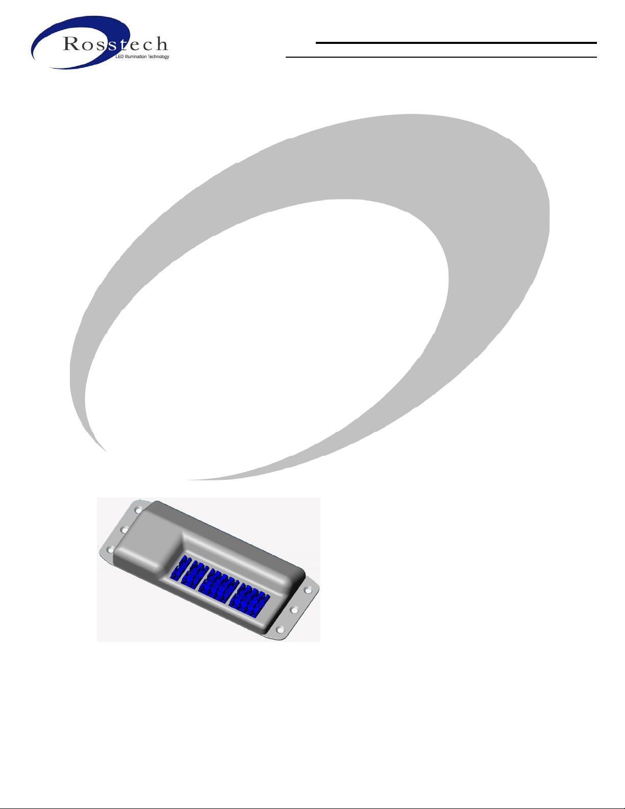
Digital Control Unit
LED Light Controller
for 2007 Production
Software Notes, Testing
and Operations Documentation
Contact: Rob Love, Rosstech Engineering
71 15th Line South RR1, Orillia, Ontario, Canada, L3V 6H1, (705) 326-3761
Rev 1.9

2007 Sundance DCU-706 Document
Includes Software, Operations and Final Testing Procedure
2 versions of software and hardware are required for 2007 production.
Sundance DCU-6560-131, SD-880 Series, PN 6560-131
2007 Features inlcude:
• Zone 3(1), RGBW, 4-O/Ps, Exterior
• Zone 2, RGB, 4-O/Ps, Top Side and waterfeature lights
• Zone 1(3), RGB, 2-O/Ps, Interior, underwater lighting
• 3 Button Auxiliary control panel functionality
• Single AC ON/OFF mode from the main control panel, to SW AC I/P
• Photocell enabled
• Temp probe and RF output enabled
• Music feature, not implemented
Jacuzzi DCU-2560-131, Jac-J300/J400 and SD-780 series, PN 6560-132/2560-131
The feature list includes all of the above features with 2 changes,
• 2 Button Auxiliary control panel functionality
• No SW AC input control, constant 12vAC power only, all operations are handled from the AUX
panel.
Software Features to implement and Basic Operational Guidelines:
The original software design is based on the 2005/2006 version of the DCU-6600 Atmel processor software
application. Basic operational features are very similar.
Bryan Huff has supplied a chart for the modes of operation he would like to see included for both a Jacuzzi
and Sundance version of the code.
Basic Mode changes for the Standard 8 Modes are listed as per Bryan Huffs Excel Spreadseet chart, which
will be included later in this document. The 5th draft rcvd Nov 14/06, has since been implemented in the
Nov 27/06 final production code.
There are 5 hidden modes on both the Jacuzzi and Sundance DCU.
Standard Modes are all available with the use of the AUX Mode button only, both versions.
Hidden Modes are available, if the lights are already ON, with a "Push and Hold" of the AUX button for 3
seconds, this will get you the first hidden mode, an additional Mode button press (short duration) will move
to the next hidden mode and so on. A 5th push of the Mode Btn will get back to the standard modes of
operation at the beginning of the sequence.
A standard 2 Hr timeout is on all standard and hidden modes.
(** Question: can we make one of the hidden modes disregard the timeout for showroom operation**)
71 15th Line South RR1, Orillia, Ontario, Canada, L3V 6H1, (705) 326-3761
Rev 1.9

2007 Sundance DCU-706 Document
Includes Software, Operations and Final Testing Procedure
New Features Controls added for this DCU
The Photocell feature and Default Mode
The Exterior Zone 3(1) will operate on photocell control.
ON during the night, OFF during the day, Exterior Zone3(1) only.
When no photocell is installed the exterior lights and iPOD white lights will be ON all the time.
If the Photocell Pins are shorted (jumpered) the lights will never be on, always OFF
**Note: A 10 second delay has been implemented in v1.40 software (Nov27/06) as per Charlie B. and
Bryans 5th draft of the requested mode.
The "default" colour mode will be initiated whenever the DCU is not in operation, so not turned on from the
AUX panel or the SW AC input.
To set/store the default colour mode:
With the interior lighting turned OFF (all lights off except the exterior on photocell control)
Simply "Push and Hold" the Mode button for 3 seconds. Upon release of the button, a new mode will be
selected, "Push and Hold" again for another 3 seconds to select the next default mode. Each "Push and
Hold" button press will cycle through the STD mode list.
Once a default mode is selected it will be remembered until the DCU power (tub power) is removed.
Intensity of the default mode is not controlled.
Temperature Probe and RF LCD Status Monitor
The DCU contains an RF transmitter, operating at 433.92MHz, it has a periodic transmission of temperature
data for a separate battery operated wireless LCD Status monitor.
The intention is that the Status monitor can sit in a consumer's kitchen and have relaitvely up to date
information ( approx. 15 minute intervals) on the status of the hot tub temperature in the backyard. This
should aid in the ability to determine if a circuit breaker has popped or a tub is shut-down, especially during
the critical cold winter months, where a freeze up would cause major disasters.
The DCU transmits an updated temperature every 11 seconds.
"Unique ID"
Each DCU will have a Unique ID so it can transmit its code and not interfere with a neighbours LCD unit.
There are 65,560 different combinations (0xFFFF), with 0xDEAD being an R&D test case.
"Offset"
Each DCU has a transmission delay upon startup based on the unique ID, this should enable tubs in the
neighbourhood, that start at the same time, possibly after a power blackout, a chance to receive a clear
transmission and not have 2 tubs broadcast at the same time. (16 variations, 1 second each)
The LCD Status monitor will need to "Bond" to the unique ID of it's respective DCU.
This is a one time procedure and does not need to be repeated for battery changes.
71 15th Line South RR1, Orillia, Ontario, Canada, L3V 6H1, (705) 326-3761
Rev 1.9

2007 Sundance DCU-706 Document
Includes Software, Operations and Final Testing Procedure
The DCU code must be able to be told to send the "Bond" command, while the LCD Status monitor is in a
"listening" for a "Bond" code, and cannot pickup a random transmission from a different tub.
To send the "Bond" command from a DCU, it must be available during any operation status (lights on or
off, 2 hr timeout On or off, AC On or Off for Sundance)
"Press and Hold" the Intensity button for 5-seconds (There is only 1 on Jacuzzi so it must be that one)
The DCU will broadcast it's "Bond" command for a period of 4-minutes along with it's temperature
transmission. Any LCD (with it's batteries freshly inserted within 20-minutes) listening during this
procedure, will be bonded to this DCU, if it does not receive it's own tranmission first.
The DCU, as long as it is powered, regardless of it's lighting status (ON or OFF), will send a periodic
transmition of its temperature. (approx every 11 seconds, for a 0.11mS 4680 baud, packet)
The actual baud rate and transmission scheme is as follows:
All packets with a 1 start bit, 0 stop bits and odd parity
11 bits/byte, 55 byte packet
(1) Sync byte and type of transmission (Bond or Temp)
(2) ID, with LSB first and inverted for Linx modules
(1) Temp packet in degrees F only now, as of v1.40
(1) CHKSM
Temperature Probe Input
The first specification for the Temperature probe to be used was the US Sensor Corp Probe.
Sundance Part # 6600-144, now changed to the GE version DC95H303W, as per Tony S.
The DCU is to be made to read the values of this probe with a provided R/T temperature curve chart.
The DCU hardware is currently set to have the Resistive thermocouple to operate from the +5v line to the
IC analog input pin, with a 18K resistor used to linearalize the termocouple for the intended range. When a
thermocouple is not installed the pin will be pulled to GND.
The LCD Status Display will read "Lo" when no probe is installed or the thermocouple cable is broken.
Upper and Lower Limits are currently set to 55F-115F, or 13C-46C. Above or below that limit will
display "Hi" or "Lo".
"Data Transmission", (4680 Baud, 8,0,1)
Data is transmitted approx every 11 seconds.
Initial data time is offset based on the inuque ID of the DCU, so all transmissions will not be happening
at the same time after a power failure.
Consists of: Sync Byte and command type(1), Unique ID Word (2), Temp (1), CHKSM(1).
"Bond" transmisstion: (4680 Baud, 8,0,1)
Sent after a 3 second intensity button push
transmission packcet is sent for 4 minutes upon regular 11 second intervals
Consists of: Sync Byte and command type(1), Unique ID Word (2), Temp (1), CHKSM(1).
71 15th Line South RR1, Orillia, Ontario, Canada, L3V 6H1, (705) 326-3761
Rev 1.9

2007 Sundance DCU-706 Document
Includes Software, Operations and Final Testing Procedure
The Music Option (not operational for the 2007 production year)
The music option will have to have some hardware additions (space available on the PCB already) for a
stereo or mono music input.
In the future this will allow the lighting to functionally "beat" with the music. Either on a simple Low
frequency beat (drums, base etc) or on a 3 frequency spectrum of highs, mediums and lows for different
colours to different beats.
Brief Software Testing Checklist
Intensity Controls - Interior / Exterior Zones (Jacuzzi 1 zone only)
- High, Med, Low, Off
Modes - 10 Standard modes
- Resets to Mode 1 after 5 seconds of Lights OFF
AC Input - With all modes, and all intensities
- test intensity controls with SW AC ON/OFF
- Sundance only, Jacuzzi test for non-functional AC
Hidden Modes - 5 hidden modes
- resets to Standard Mode 1 after lights off
Exterior 'default' modes - Press and hold mode button
Photocell control - 10 second delay on change, start right away on lights OFF
Temp Output - 11 second output
- Bond command by push and hold of correct intensity button
Unique ID - Test for unique ID update for LCD Status Monitor
2 Hour Timeout
71 15th Line South RR1, Orillia, Ontario, Canada, L3V 6H1, (705) 326-3761
Rev 1.9

2007 Sundance DCU-706 Document
Includes Software, Operations and Final Testing Procedure
LCD Status Monitor Basic Software Specification and Operation
LCD code operation:
Batteries are inserted, waits for a 20 minute period for new "Bond" command
Flashes green if it already has a unique ID number in memory.
Displays -- (2 dashes). Once the unit receives an update or the "Bond" command, it will display the current
temperature.
Wakes up listens for signal:
rcvs signal
checks timing value
displays temp value
changes status to flash green (which is the same as previous?)
if no signal is rcvd after 34 seconds, go to sleep wait for 15 minutes, lsiten for signal for 34 seconds.
Change status LED to flash RED if it misses 2 updates (30 minutes)
Change the display to remove the temperature reading and display -- , after 2 additional losses of signal
(total time 1Hr)
Continues to flash Red with no display, until a return of the signal or the battery dies.
If the signal returns (ie: after power failure),
changes status LED to flash green
Displays Temp
Test condition:
A new LCD unit that is not "Bonded" to a unique ID will always recognize and display a temperature from a
unique ID of 0xDEAD for test purposes.
71 15th Line South RR1, Orillia, Ontario, Canada, L3V 6H1, (705) 326-3761
Rev 1.9

2007 Sundance DCU-706 Document
Includes Software, Operations and Final Testing Procedure
LCD Status Monitor Point Form Installation and Operation Notes
• Remove unit from packaging
• Remove 2 screws from back cover
• Monitor is factory set to indicate degrees in Fahrenheit, for Celsius display, move the small black jumper
(located on a 3-pin header below the battery housing) from the left two pins to the right two pins.
• Insert 3 x "AAA" batteries (Alkaline or Lithium recommended)
• Replace the cover and screws
• First time installing batteries:
o Set the Status Monitor on or near the hot tub
o Within 15 minutes of installing the batteries, on the hot tub lighting controls, press and hold the light
intensity button (waterfall intensity on SD 880 series) for 10 seconds to ‘bond’ the receiver.
o Within 1 minute of bonding, the display will update with a temperature indication and the LED
indicator will start flashing green every 15-30 seconds.
• Future battery changes – simply replace ALL 3 BATTERIES and allow the unit time to receive several
updates (30 minutes to 1 hour)
• If unit does not appear to update properly (after 1 Hr)
o Ensure the tub is powered properly.
o Move the unit closer to the tub to ensure it receives an update.
o It is recommended to wait for 1Hr to ensure reception of several updates.
• Effective range is approx 150 ft in clear line of sight. Each obstacle (ie. wall, fence, window, pet, family
member) will decrease this range. Range can also be affected by battery condition.
• If the unit indicates 'Lo' with no temperature units displayed, it could be indicating a problem with the
thermocouple connection to the Lighting Controller.
• You may reverse the stand included on the back of the unit to make it a desk top unit.
o Squeeze the arms at the top of the stand together to release it from the housing.
o Reverse the stand and re-install the arms, forming a tripod stand.
71 15th Line South RR1, Orillia, Ontario, Canada, L3V 6H1, (705) 326-3761
Rev 1.9

2007 Sundance DCU-706 Document
Includes Software, Operations and Final Testing Procedure
Current Mode List Summary:
(Sundance 6560-131 and Jacuzzi 2560-131 modes are identical as of 5th draft requests, Nov 27/06)
Mode 1 – Medium Rotate
Mode 2 – Slow Rotate
Mode 3 – Freeze Mode
Mode 4 – Blue
Mode 5 – Purple (Red/Blue)
Mode 6 – Red
Mode 7 – Amber (Grn/Red)
Mode 8 – Green
Mode 9 – Aqua (Grn/Blue)
Mode 10 – Simulated White (Red/Grn/Blue)
Hid-Mode 1 – Very Fast Rotate
Hid-Mode 2 – Mixed Slow Rotate, Topside different then Interior and Exterior
Hid-Mode 3 – Mixed Slow Rotate, All zones different
Hid-Mode 4 – Mixed Fast Rotate, Topside different then Interior and Exterior
Hid-Mode 5 – Mixed Fast Rotate, All zones different
-Mode setting resets to Mode 1 after lights being off for 5 seconds.
-Hidden-Mode settings reset back to standard modes as soon as lights are turned off.
71 15th Line South RR1, Orillia, Ontario, Canada, L3V 6H1, (705) 326-3761
Rev 1.9

2007 Sundance DCU-706 Document
Includes Software, Operations and Final Testing Procedure
Final Test Procedure: 6560-131
Sundance 2-Wire Systems, while in the Blue Boxes
Connect DCU Blue
and Gray Wire
Connect Lights
Observe for Zone 1
Install photocell
Press Intensity
Button 1
Press Intensity
Button 2
Press Mode Button
Press AC ON/OFF
Visual for Temp Cal
Visual DCU
* Notes:
The Mode setting will reset to the beginning of the Mode list after the lights being off for more then 5
seconds.
Observe for Blue lights
Observe for Red/Blue/White on Exterior Zone 1
Observe Lights on Zone 3 and White still on
Observe Lights on Zone 2, 3 and White still on
Press the Mode button a couple of times,
Observe for Solid Blue, all 3 zones, and White
Press Mode 2 more times, observe Solid Red, all 3 zones, and White
Press Mode 2 more times, observe Solid Green, all 3 zones and White
observe White light should not turn off or dim during mode changes
The lights will remain ON for the first push then go completely out for the
second button push.
Make sure the Exterior Zone 1 Lights are off, if the photocell is installed
Visual for temperature calibration written on the board from the initial test
Pass to next step for packaging
Install FCC and Part # label
Count the screws installed
General inspection
71 15th Line South RR1, Orillia, Ontario, Canada, L3V 6H1, (705) 326-3761
Rev 1.9

2007 Sundance DCU-706 Document
Includes Software, Operations and Final Testing Procedure
Final Test Procedure: 2560-131
Jacuzzi Single Wire Systems, while in the Blue Boxes
Connect DCU Blue
Pwr Wire
Connect Lights
Observe for Zone 1
Install photocell
Press Intensity
Press Mode Button
Press Intensity
Visual for Temp Cal
Visual DCU
* Notes:
Jacuzzi 2560-131 programming, has 2 Button control panel.
All 3 zones will always work in sequence with each other, unless the "Hidden Modes" are selected.
Jacuzzi 2560-131 does not have a switched AC input. (Grey wire)
The Mode setting will reset to the beginning of the Mode list after the lights being off for more then 5
seconds.
Observe for Blue lights
Observe for Red/Blue/White on Exterior Zone 1
Observe Lights on Zone 1, 2, 3 and White still on
Press the Mode button a couple of times,
Observe for Solid Blue, all 3 zones, and White
Press Mode 2 more times, observe Solid Red, all 3 zones, and White
Press Mode 2 more times, observe Solid Green, all 3 zones and White
observe White light should not turn off or dim during mode changes
Press Intensity observe for change from High to Med, to Low, to OFF
With Photocell plugged in (step 4) there should be NO LIGHTS on Zone 1
Visual for temperature calibration written on the board from the initial test
Pass to next step for packaging
Install FCC and Part # label
Count the screws installed
General inspection
71 15th Line South RR1, Orillia, Ontario, Canada, L3V 6H1, (705) 326-3761
Rev 1.9

2007 Sundance DCU-706 Document
Includes Software, Operations and Final Testing Procedure
DCU-706, Digital LED Lighting Control Unit, 2007 Production
Electrical
Input…………………………………………..12vAC, +2vAC (10-14vAC)
Blue, 18 awg PVC jcktd wire
Power Consumption…………………………...0.8A typ. max.
SW 12vAC input control (optional)…………...12vAC, +4vAC (8-16vAC)
SW 12vAC input power consumption…………<0.01A, isolated I/P
Grey, 22awg PVC jcktd wire
Inputs
AUX Control Input............................................10-Pin Male Header, for up to a 4-Btn AUX
Control panel
In Circuit Programming..(via the AUX cnctr)...10-Pin Male Header, 5-pins rqrd
Temp Probe Input...............................................GE thermocouple, 30K ohms at 25C
Molex/Amp 2-Pin 0.100" male header
Photocell Input....................................................CDS Photocell, 5K Dark, >100K Bright
Molex/Amp 2-Pin 0.100" male header
Music Input.........................................................(Not used at this time)
Outputs
3 Zones of LED Lighting Control Outputs
Zone 1* – Exterior, 4-10-Pin male headers, RGBW LED control
Zone 2 – Top Side Zone, 4-10-Pin male headers, RGB LED control
Zone 3* – Interior Zone, 2-10-Pin male headers, RGB LED control
*Note, initial Zone markings are opposite on plastic DCU boxes, as per the PCB and documentation
reference.
** LED outputs are for use with Rosstech LED accessory lighting applications only **
71 15th Line South RR1, Orillia, Ontario, Canada, L3V 6H1, (705) 326-3761
Rev 1.9

2007 Sundance DCU-706 Document
Includes Software, Operations and Final Testing Procedure
1. FCC Information to Users @ FCC 15.21 & 15.105
Compliance Statement
Warning: Changes or modifications not expressly approved by Rosstech Signals Inc. could void the user’s
authority to operate the equipment
This equipment has been tested and found to comply with the limits for a Class B digital devices, pursuant to Part
15 of the FCC Rules. These limits are designed to provide reasonable protection against harmful interference in a
residential installation. This equipment generates, uses, and can radiate radio frequency energy and, if not
installed and used in accordance with the instruction manual, may cause harmful interference to radio
communications. However, there is no guarantee that interference will not occur in a particular installation. If this
equipment does cause harmful interference to radio or television reception, which can be determined by turning
the equipment off and on, the user is encouraged to try to correct the interference by one of more of the following
measures:
• Reorient or relocate the receiving antenna
• Increase the separation between the equipment and receiver
• Connect the equipment into an outlet on a circuit different from that to which the receiver is
connected.
• Consult the dealer or an experienced radio/TV technician for help.
Revision Notes and History Page
Revision Notes and History
Notes and Changes Date Initials Rev #
Initial Document creation
Operation software updates
Show operation changes
Nov – Production code changes
Nov – FCC changes for packet information
Nov – 5th draft Sundance mode changes implemented
Added software check list
New Processor notes, CY8C27443-24PVXI, New Tx2000 RF Module
Updated LCD info for v40 s/w, broadcast F only, displays 'Lo' no probe inst.
Added the FCC Information to Users
Sep 26/06
Oct 17/06
Oct 20/06
Nov 15/06
Nov 22/06
Nov 27/06
Dec 11/06
Feb 19/07
Feb 23/07
Mar 13/07
RL 1.0
RL 1.1
RL 1.2
RL 1.3
RL 1.4
RL 1.5
RL 1.6
RL 1.7
RL 1.8
RL 1.9
71 15th Line South RR1, Orillia, Ontario, Canada, L3V 6H1, (705) 326-3761
Rev 1.9
 Loading...