

Page 1
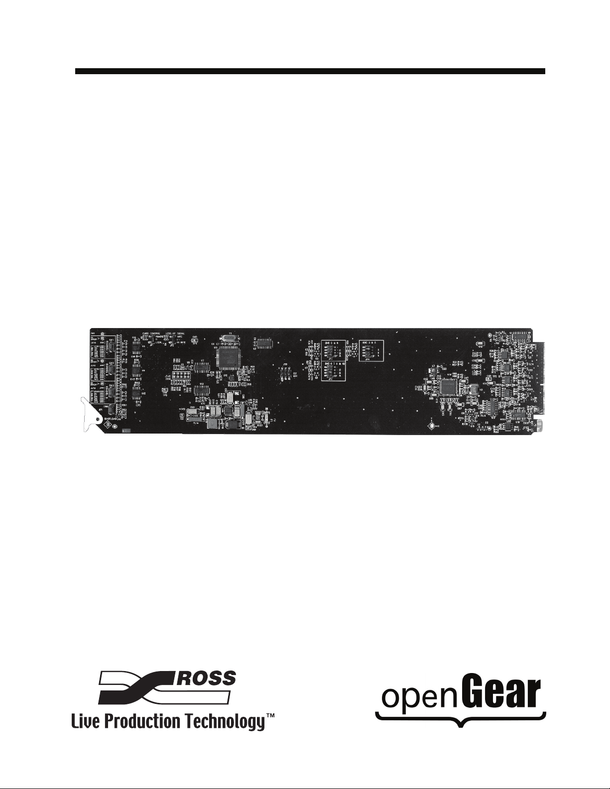
Ross Video Limited
TRA-8206
Triple MD-SDI Reclocking Amplifier
User Manual
Page 2

TRA-8206 • Triple MD-SDI Reclocking Amplifier User Manual
• Ross Part Number: 8206DR-004-05
• Release Date: March 17, 2010. Printed in Canada.
The information contained in this manual is subject to change without notice or obligation.
Copyright
© 2010 Ross Video Limited. All rights reserved.
Contents of this publication may not be reproduced in any form without the written permission of
Ross Video Limited. Reproduction or reverse engineering of copyrighted software is prohibited.
Patents
This product is protected by the following US Patents: 4,205,346; 5,115,314; 5,280,346;
5,561,404; 7,034,886; 7,508,455. This product is protected by the following Canadian Patents:
2039277; 1237518; 1127289. Other patents pending.
Notice
The material in this manual is furnished for informational use only. It is subject to change without
notice and should not be construed as commitment by Ross Video Limited. Ross Video Limited
assumes no responsibility or liability for errors or inaccuracies that may appear in this manual.
Trademarks
• is a registered trademark of Ross Video Limited.
• is a trademark of Ross Video Limited.
®
• Ross, ROSS, ROSS
• DashBoard Control System™ is a trademark of Ross Video Limited.
• All other product names and any registered and unregistered trademarks mentioned in
this guide are used for identification purposes only and remain the exclusive property of
their respective owners.
are registered trademarks of Ross Video Limited.
Page 3

Important Regulatory and Safety Notices
Before using this product and any associated equipment, refer to the “Important Safety
Instructions” listed below to avoid personnel injury and to prevent product damage.
Products may require specific equipment, and/or installation procedures to be carried out to
satisfy certain regulatory compliance requirements. Notices have been included in this
publication to call attention to these specific requirements.
Symbol Meanings
This symbol on the equipment refers you to important operating and maintenance
(servicing) instructions within the Product Manual Documentation. Failure to heed this
information may present a major risk of damage or injury to persons or equipment.
Warning — The symbol with the word “Warning” within the equipment manual
indicates a potentially hazardous situation which, if not avoided, could result in death
or serious injury.
Caution — The symbol with the word “Caution” within the equipment manual
indicates a potentially hazardous situation which, if not avoided, may result in minor
or moderate injury. It may also be used to alert against unsafe practices.
Notice — The symbol with the word “Notice” within the equipment manual indicates
a situation, which if not avoided, may result in major or minor equipment damage or a
situation which could place the equipment in a non-compliant operating state.
ESD Susceptibility — This symbol is used to alert the user that an electrical or
electronic device or assembly is susceptible to damage from an ESD event.
Important Safety Instructions
Caution — his product is intended to be a component product of the DFR-8300
series frame. Refer to the DFR-8300 series frame User Manual for important safety
instructions regarding the proper installation and safe operation of the frame as well
as its component products.
Warning — Certain parts of this equipment namely the power supply area still
present a safety hazard, with the power switch in the OFF position. To avoid electrical
shock, disconnect all A/C power cards from the chassis’ rear appliance connectors
before servicing this area.
Warning — Service barriers within this product are intended to protect the operator
and service personnel from hazardous voltages. For continued safety, replace all
ba rr ie rs aft er a ny se rv ici ng .
This product contains safety critical parts, which if incorrectly replaced may present a
risk of fire or electrical shock. Components contained with the product’s power
supplies and power supply area, are not intended to be customer serviced and should
be returned to the factory for repair. To reduce the risk of fire, replacement fuses must
be the same time and rating. Only use attachments/accessories specified by the
manufacturer.
Page 4
EMC Notices
United States of America
FCC Part 15
This equipment has been tested and found to comply with the limits for a class A Digital device,
pursuant to part 15 of the FCC Rules. These limits are designed to provide reasonable protection
against harmful interference when the equipment is operated in a commercial environment. This
equipment generates, uses, and can radiate radio frequency energy and, if not installed and used
in accordance with the instruction manual, may cause harmful interference to radio
communications. Operation of this equipment in a residential area is likely to cause harmful
interference in which case the user will be required to correct the interference at his own expense.
Notice — Changes or modifications to this equipment not expressly approved by
Ross Video Limited could void the user’s authority to operate this equipment.
CANADA
This Class “A” digital apparatus complies with Canadian ICES-003.
Cet appariel numerique de la classe “A” est conforme a la norme NMB-003 du Canada.
EUROPE
This equipment is in compliance with the essential requirements and other relevant provisions of
CE Directive 93/68/EEC.
INTERNATIONAL
This equipment has been tested to CISPR 22:1997 along with amendments A1:2000 and
A2:2002, and found to comply with the limits for a Class A Digital device.
Notice — This is a Class A product. In domestic environments, this product may
cause radio interference, in which case the user may have to take adequate
measures.
Maintenance/User Serviceable Parts
Routine maintenance to this openGear product is not required. This product contains no user
serviceable parts. If the module does not appear to be working properly, please contact Technical
Support using the numbers listed under the “Contact Us” section on the last page of this manual.
All openGear products are covered by a generous 5-year warranty and will be repaired without
charge for materials or labor within this period. See the “Warranty and Repair Policy” section in
this manual for details.
Page 5

Environmental Information
The equipment that you purchased required the extraction and use of natural
resources for its production. It may contain hazardous substances that could
impact health and the environment.
To avoid the potential release of those substances into the environment and to diminish the need
for the extraction of natural resources, Ross Video encourages you to use the appropriate
take-back systems. These systems will reuse or recycle most of the materials from your
end-of-life equipment in an environmentally friendly and health conscious manner.
The crossed-out wheeled bin symbol invites you to use these systems.
If you need more information on the collection, reuse, and recycling systems, please contact your
local or regional waste administration. You can also contact Ross Video for more information on
the environmental performances of our products.
Page 6

Company Address
Ross Video Limited
8 John Street
Iroquois, Ontario
Canada, K0E 1K0
General Business Office: (+1) 613 • 652 • 4886
Technical Support: (+1) 613 • 652 • 4886
After Hours Emergency: (+1) 613 • 349 • 0006
E-mail (Technical Support): [email protected]
E-mail (General Information): [email protected]
Website: http://www.rossvideo.com
Ross Video Incorporated
P.O. Box 880
Ogdensburg, New York
USA 13669-0880
Fax: (+1) 613 • 652 • 4425
Page 7

Contents
Introduction 1
Overview.............................................................................................................................. 1-2
Features.................................................................................................................. 1-2
Functional Block Diagram................................................................................................... 1-3
Documentation Terms and Conventions.............................................................................. 1-4
Installation 2
Before You Begin ................................................................................................................2-2
Static Discharge..................................................................................................... 2-2
Unpacking.............................................................................................................. 2-2
Installing the TRA-8206 ...................................................................................................... 2-3
Rear Modules for the TRA-8206........................................................................... 2-3
Installing a Rear Module ....................................................................................... 2-3
Board Installation .................................................................................................. 2-4
Cabling for the TRA-8206................................................................................................... 2-5
Connections for the DFR-8310 Series Frames...................................................... 2-5
Connections for the DFR-8321 Series Frames...................................................... 2-5
User Controls 3
Card Overview..................................................................................................................... 3-2
Output Channel Configuration............................................................................................. 3-4
Channel Rate Selection Buttons and LEDs........................................................... 3-4
Single, Dual, or Triple Channel Jumper Configurations ...................................... 3-5
Control and Monitoring ....................................................................................................... 3-6
Status and Selection LEDs on the TRA-8206 ....................................................... 3-6
Factory Default Values.......................................................................................... 3-7
Reclocker Rate Selection ..................................................................................................... 3-8
Reclocker Rate Selection LEDs ............................................................................ 3-8
Menus 4
SNMP Monitoring and Control ........................................................................................... 4-2
Dashboard Control System Software................................................................................... 4-3
Status Tabs ............................................................................................................ 4-3
Setup Menus .......................................................................................................... 4-4
Routing Menus ...................................................................................................... 4-4
Alarms Menus ....................................................................................................... 4-5
Specifications 5
Technical Specifications ...................................................................................................... 5-2
Service Information 6
Troubleshooting Checklist................................................................................................... 6-2
Bootload Button .................................................................................................... 6-2
Warranty and Repair Policy................................................................................................. 6-3
TRA-8206 User Manual (Iss. 05) Contents • i
Page 8

ii • Contents TRA-8206 User Manual (Iss. 05)
Page 9

Introduction
In This Chapter
This chapter contains the following sections:
• Overview
• Functional Block Diagram
• Documentation Terms and Conventions
A Word of Thanks
Congratulations on choosing an openGear TRA-8206 Triple MD-SDI Reclocking Amplifier.
Your TRA-8206 is part of a full line of Digital Products within the openGear Terminal Equipment
family of products, backed by Ross Video's experience in engineering and design expertise since
1974.
You will be pleased at how easily your new TRA-8206 fits into your overall working
environment. Equally pleasing is the product quality, reliability and functionality. Thank you for
joining the group of worldwide satisfied Ross Video customers!
Should you have a question pertaining to the installation or operation of your TRA-8206, please
contact us at the numbers listed on the back cover of this manual. Our technical support staff is
always available for consultation, training, or service.
TRA-8206 User Manual (Iss. 05) Introduction • 1–1
Page 10

Overview
Features
The TRA-8206 is a three channel Multi-Definition SDI distribution amplifier, capable of
equalizing and reclocking all common serial digital signals. Support for both standard-definition
and high-definition signals makes the TRA-8206 a universal SDI distribution amplifier.
Each channel of the TRA-8206 equalizes the incoming SDI signal, compensating for up to 300m
of cable at 270Mbps and over 120m of cable at 1.485Gbps. The signal is then reclocked, with
automatic rate detection for all popular data rates. Each channel is fully independent and can run
at different data rates. LED indicators at the front of the card identify the presence of incoming
video and the identified signal data rate for each channel independently.
A special feature of the TRA-8206 is the ability to operate in a number of different channel
configurations. The triple channel mode is ideal for applications requiring only 1 or 2 outputs,
such as mid-cable signal boosters, router expansion, or signal cleanup. Up to 30 SDI distribution
channels can be housed in a 2RU space.
Special attention has been taken to ensure the SDI outputs faithfully reproduce the incoming
signals, with excellent jitter and return loss specifications.
LED indicators at the front of the card identify the presence of incoming video, simplifying
system troubleshooting.
The following features make the TRA-8206 the best solution for general SDI equalizing,
reclocking, and distribution:
• Three independent channels of SDI distribution
• Flexible channel configurations:
› Single channel 1:7 amplifier
› Dual channel 1:4 + 1:3 amplifier
› Dual channel 1:5 + 1:2 amplifier
› Triple channel 1:3 + 1:2 + 1:2 amplifier
• Equalizes and reclocks all popular SDI signals from 143Mbps to 1.485Gbps
• Equalizes up to 300m of Belden 1694A cable at 270Mbps, or over 120m of cable at
1.485Gbps
• Automatic detection of incoming data rate
• LED indicators for signal presence and data rate for each channel
• Excellent input and output return loss exceeds SMPTE specifications
• Fits openGear DFR-8300 series frames
• 5 year transferable warranty
1–2 • Introduction TRA-8206 User Manual (Iss. 05)
Page 11

Functional Block Diagram
Equalizer
Equalizer
Equalizer
Reclocker
Reclocker
Reclocker
Channel A
BNC 1
Channel B
BNC 9
Channel C
BNC 10
SDI OUT
BNC 2
BNC 4
BNC 3
BNC 5
BNC 6
BNC 7
BNC 8
Crosspoint
This section provides a functional block diagram that outlines the workflow of the TRA-8206.
Figure 1.1 TRA-8206 — Simplified Block Diagram
TRA-8206 User Manual (Iss. 05) Introduction • 1–3
Page 12

Documentation Terms and Conventions
The following terms are used throughout this manual:
•“Frame” refers to the DFR-8300 series frame that houses the TRA-8206 card.
• All references to the DFR-8300 series frame also include the 10-slot versions
(DFR-8310) and the 20-slot frame versions (DFR-8321 series).
•“Operator” and “User” both refer to the person who uses the TRA-8206.
•“Board” and “Card” both refer to the TRA-8206 card itself, including all components
and switches.
•“System” and “Video system” both refer to the mix of interconnected production and
terminal equipment in which the TRA-8206 operates.
•“DashBoard” refer to the DashBoard Control System™.
• The “Operating Tip” and “Note” boxes are used throughout this manual to provide
additional user information.
1–4 • Introduction TRA-8206 User Manual (Iss. 05)
Page 13

Installation
In This Chapter
This chapter provides instructions for installing the rear module(s) for the TRA-8206, installing
the card into the frame, and cabling details.
The following topics are discussed:
• Before You Begin
• Installing the TRA-8206
• Cabling for the TRA-8206
TRA-8206 User Manual (Iss. 05) Installation • 2–1
Page 14

Before You Begin
Before proceeding with the instructions in this chapter, ensure that your DFR-8300 series frame is
properly installed according to the instructions in the DFR-8300 Series User Manual.
Static Discharge
Whenever handling the TRA-8206 and other related equipment, please observe all static
discharge precautions as described in the following note:
ESD Susceptibility — Static discharge can cause serious damage to sensitive
semiconductor devices. Avoid handling circuit boards in high static environments
such as carpeted areas and when synthetic fiber clothing is worn. Always exercise
proper grounding precautions when working on circuit boards and related
equipment.
Unpacking
Unpack each TRA-8206 you received from the shipping container and ensure that all items are
included. If any items are missing or damaged, contact your sales representative or Ross Video
directly.
2–2 • Installation TRA-8206 User Manual (Iss. 05)
Page 15

Installing the TRA-8206
The TRA-8206 is compatible with the DFR-8300 series frames. The procedure for installing the
rear module in your openGear frame is the same regardless of the frame, module, or card used.
Rear Modules for the TRA-8206
The rear module for the TRA-8206 depends on the openGear frame you are installing the card
into.
• DFR-8310 series frames — When installing the TRA-8206 in a DFR-8310 series frame,
the 8310AR-030 Rear Module (R1-8206) is required. The TRA-8206 is also compatible
with the DFR-8310-BNC frames.
• DFR-8321 series frames — When installing the TRA-8206 in a DFR-8321 series frame,
the 8320AR-030 Full Rear Module (R2-8206) is required.
Installing a Rear Module
If you are installing the TRA-8206 in a DFR-8310-BNC frame, or if the rear module is already
present, skip this section.
Use the following procedure to install the rear module in a DFR-8300 series frame:
1. Refer to the DFR-8300 Series User Manual to ensure that the frame is properly
installed according to instructions.
2. Locate the card frame slot on the rear of the frame.
3. Remove the Blank Plate from the rear of the slot you have chosen for card installation.
4. As shown in Figure 2.1, seat the bottom of the rear module in the seating slot at the base
of the frame’s back plane.
Figure 2.1 Rear Module Installation in a DFR-8310 Series Frame (TRA-8206 not shown)
TRA-8206 User Manual (Iss. 05) Installation • 2–3
Page 16

5. Align the top hole of the rear module with the screw hole on the top edge of the frame
back plane.
6. Using a Phillips screwdriver and the supplied screw, fasten the rear module to the frame
back plane. Do not over tighten.
7. Ensure proper frame cooling and ventilation by having all rear frame slots covered with
rear modules or blank metal plates.
This completes the procedure for installing rear module in a DFR-8300 series frame.
Board Installation
Use the following procedure to install the TRA-8206 in a DFR-8300 series frame:
1. Refer to the DFR-8300 Series User Manual to ensure that the frame is properly
installed according to instructions.
Note — Heat and power distribution requirements within a frame may dictate
specific slot placement of cards. Cards with many heat-producing components should
be arranged to avoid areas of excess heat build-up, particularly in frames using
convectional cooling.
2. After selecting the desired frame installation slot, hold the TRA-8206 card by the edges
and carefully align the card edges with the slots in the frame.
3. Fully insert the card into the frame until the rear connection plugs are properly seated on
the midplane and rear modules.
4. Affix the supplied BNC label to the BNC area on the rear module.
This completes the procedure for installing the TRA-8206 in a DFR-8300 series frame.
For More Information...
• on the assignment of input channels to output BNCs via jumper selection, refer to the
section “Output Channel Configuration” on page 3-4.
2–4 • Installation TRA-8206 User Manual (Iss. 05)
Page 17

Cabling for the TRA-8206
This section provides instructions for connecting cables to the installed rear modules on the
DFR-8300 series frame backplane. The inputs are internally terminated in 75ohms. It is not
necessary to terminate unused outputs.
Connections for the DFR-8310 Series Frames
In the DFR-8310 series frame, the TRA-8206 occupies one slot and provides seven SDI outputs
and three SDI inputs. Connect the input and output cables according to Figure 2.2.
SDI In
Channel A
SDI Out 2
SDI Out 2
SDI Out 3
SDI In
Channel B
2
1
4
3
6
5
8
7
10
9
SDI Out 1
SDI Out 1
SDI Out 3
SDI Out 3
SDI In
Channel C
Figure 2.2 Cable Connections for the TRA-8206
Connections for the DFR-8321 Series Frames
In the DFR-8321 series frame, the TRA-8206 occupies one slot and provides seven SDI outputs
and three SDI inputs. Connect the input and output cables according to Figure 2.2.
TRA-8206 User Manual (Iss. 05) Installation • 2–5
Page 18

2–6 • Installation TRA-8206 User Manual (Iss. 05)
Page 19

User Controls
In This Chapter
This chapter provides a general overview of the user controls available on the TRA-8206.
The following topics are discussed:
• Card Overview
• Output Channel Configuration
• Control and Monitoring
• Reclocker Rate Selection
TRA-8206 User Manual (Iss. 05) User Controls • 3–1
Page 20

Card Overview
1 2
3
4
5
6
7 8
9
The following figure and discussions describe the jumpers and controls on the TRA-8206.
Figure 3.1 Card-edge Controls
1) Card Control (JP1) 4) Channel B Rate Selection (SW2) 7) BNC 2 and 4 Output Configuration (JP3)
2) Loss of Signal (JP2) 5) Channel C Rate Selection (SW3) 8) BNC 3 and 5 Output Configuration (JP4)
3) Channel A Rate Selection (SW1) 6) Bootload Button (SW4) 9) BNC 6, 7, 8 Output Configuration (JP5)
1. Card Control (JP1)
Use JP1 to select whether the Output Mute and Output Channel Configuration jumper settings
are respected or ignored by remote control settings. Select one of the following options:
• REMOTE — the local jumper settings are ignored and the card is configured remotely.
• LOCAL — the local jumper settings are respected and card is controlled locally. The
card controls and status can be read remotely but not changed (default setting).
Note — This setting applies to control of the jumpers only. Card-edge buttons and
switch settings can be configured remotely or locally in either setting.
2. Loss of Signal (JP2)
Use JP2 to enable or disable the Loss of Signal option as follows:
• MUTE — a channel’s outputs will be muted if the input signal degrades to the point that
the input EQ can no longer guarantee error-free performance. When the red ERROR LED
is lit, the outputs will be muted.
mode, we recommend this jumper position. The output of the card would then mute if an
incorrect data rate is applied to the input, or if the input signal became too weak for the
input equalizer to compensate.
• NO MUTE — a channel’s outputs will work to the limits of the input stage (default
setting).
3. Channel A Rate Selection (SW1)
Channel A has a rate selection button and corresponding SD and HD LEDs. Use the rate selection
button and LEDs to set the input signal rate type that Channel A will process. Pressing the button
cycles between the HD and SD options. You can choose between the following signal rate types:
• HD — Select this option when using 1.485Gbps rate.
• SD — Select this option when using 143, 177, 270, 360, and 540Mbps rates.
4. Channel B Rate Selection (SW2)
If you have input channels set to any rate other than Auto
3–2 • User Controls TRA-8206 User Manual (Iss. 05)
Channel B has a rate selection button and corresponding SD and HD LEDs. Use the rate selection
button and LEDs to set the input signal rate type that Channel B will process. Pressing the button
cycles between the HD and SD options. You can choose between the following signal rate types:
Page 21

• HD — Select this option when using 1.485Gbps rate.
• SD — Select this option when using 143, 177, 270, 360, and 540Mbps rates.
5. Channel C Rate Selection (SW3)
Channel C has a rate selection button and corresponding SD and HD LEDs. Use the rate selection
button and LEDs to set the input signal rate type that Channel C will process. Pressing the button
cycles between the HD and SD options. You can choose between the following signal rate types:
• HD — Select this option when using 1.485Gbps rate.
• SD — Select this option when using 143, 177, 270, 360, and 540Mbps rates.
6. Bootload Button (SW4)
This button is used for factory service in the unlikely event of a complete card failure. The
Bootload process is further described in the “Bootload Button” on page 6-2.
7. BNC 2 and 4 Output Configuration (JP3)
Use JP3 to select one of the following input channels to output on BNC 2 and BNC 4:
• A — BNC 2 and BNC 4 will output the signal input on Channel A.
• B — BNC 2 and BNC 4 will output the signal input on Channel B (default setting).
• C — Position C is not used on the TRA-8206 and should not be selected.
• Blank — The top blank position for these jumpers is for factory use, and should not be
selected for normal operation. If selected, the BNCs output the signal input on Channel
A.
• None — If the jumper is removed, the BNCs will output the signal input on Channel A.
8. BNC 3 and 5 Output Configuration (JP4)
Use JP4 to select one of the following input channels to output on BNC 3 and BNC 5:
• A — BNC 3 and BNC 5 will output the signal input on Channel A.
• B — BNC 3 and BNC 5 will output the signal input on Channel B (default setting).
• C — Position C is not used on the TRA-8206 and should not be selected.
• Blank — The top blank position for these jumpers is for factory use, and should not be
selected for normal operation. If you select this position, the BNCs will output the signal
input on Channel A.
• None — If the jumper is removed, the BNCs will output the signal input on Channel A.
9. BNC 6, 7, 8 Output Configuration (JP5)
Use JP5 to select one of the following input channels to output on BNC 6, 7, and 8:
• A — BNC 6, 7, and 8 will output the signal input on Channel A.
• B — BNC 6, 7, and 8 will output the signal input on Channel B (default setting).
• C — Position C is not used on the TRA-8206 and should not be selected.
• Blank — The top blank position for these jumpers is for factory use, and should not be
selected for normal operation. If you select this position, the BNCs will output the signal
input on Channel A.
• None — If the jumper is removed, the BNCs will output the signal input on Channel A.
TRA-8206 User Manual (Iss. 05) User Controls • 3–3
Page 22

Output Channel Configuration
A special feature of the TRA-8206 is the ability to operate in a number of different channel
configurations. By simply changing channel jumpers, the TRA-8206 can be configured in the
following ways:
• Single channel ⎯ 1:7
• Dual channel ⎯ 1:4 + 1:3
• Dual channel ⎯ 1:5 + 1:2
• Triple channel ⎯ 1:3 + 1:2 + 1:2 (Default setting)
Figure 3.2 Channel Output Jumpers
Note — Position C is not used on the TRA-8206 and should not be selected. The top
empty position for each jumper is for factory use only.
Channel Rate Selection Buttons and LEDs
Each channel has a channel rate selector button and rate LEDs to set the input signal rate that the
channel will process. Pressing the button illuminates a corresponding LED. Repeated presses will
cycle through the selections.
For most applications, setting the Channel Rate to AUTO (default setting) will allow the
TRA-8206 to automatically detect the incoming data rate. In the AUTO mode, the Data Rate
LEDs will display the data rate detected from the incoming SDI signal.
For applications where only one specific data rate will be used, and the fastest possible lock times
are desired, the TRA-8206 can be set and locked to a specific data rate. Press the Channel Rate
Selection Button until the AUTO LED is off, and the specific data rate LED is illuminated.
Only SDI signals matching the selected data rate will be reclocked and passed through the
TRA-8206.
3–4 • User Controls TRA-8206 User Manual (Iss. 05)
Page 23

Single, Dual, or Triple Channel Jumper Configurations
Use Ta bl e 3 .1 to configure your channel for single, dual, or triple channel operation.
Table 3.1 Output Configuration
Configuration JP3 JP4 JP5
Input Channel A: Output BNCs 2 to 8 A A A
Single Channel 1:7
Dual Channel
1:4 + 1:3 (default)
Dual Channel
1:5 + 1:2
Triple Channel
1:2+1:2+1:3
(default)
Input Channel B: Output BNCs 2 to 8 B B B
Input Channel C: Output BNCs 2 to 8 C C C
Input Channel A: Output BNCs 2 to 5
Input Channel B: Output BNCs 6, 7, 8
Input Channel A: Output BNCs 2 to 5
Input Channel C: Output BNCs 6, 7, 8
Input Channel B: Output BNCs 2 to 5
Input Channel C: Output BNCs 6, 7, 8
Input Channel A: Output BNCs 2, 4, 6, 7, 8
Input Channel B: Output BNCs 3, 5
Input Channel A: Output BNCs 2, 4
Input Channel B: Output BNCs 3, 5, 6, 7, 8
Input Channel A: Output BNCs 2, 4, 6, 7, 8
Input Channel C: Output BNCs 3, 5
Input Channel A: Output BNCs 2, 4
Input Channel B: Output BNCs 3, 5
Input Channel C: Output BNCs 6, 7, 8
AAB
AAC
BBC
ABA
ABB
ACA
ABC
TRA-8206 User Manual (Iss. 05) User Controls • 3–5
Page 24

Control and Monitoring
This section provides information on the card-edge LEDs of the TRA-8206. Refer to Figure 3.3
for the location of the LEDs.
PWR LED
OK/ERROR LED
HD LED
Channel A
OK/ERROR LED
Channel C
SD LED
Channel A
Rate Selection
HD LED
SD LED
Channel C
Rate Selection
OK/ERROR LED
HD LED
SD LED
Channel B
Rate Selection
Bootload Button
Channel B
Figure 3.3 LED and Rate Selection Switch Locations
Status and Selection LEDs on the TRA-8206
The front-edge of the TRA-8206 has LED indicators for the power, channel status, and
communication activity. Basic LED displays and descriptions are provided in Tab le 3 .2 .
Table 3.2 LEDs on the TRA-8206
LED Color Display and Description
When lit green, this LED indicates that the card is functioning
normal and that no anomalies have been detected. The following
Green
Flashing Green
PWR
Flashing Green
and Orange
Amber
conditions must be satisfied:
• a valid input signal is present
• a valid reference signal is present when a reference is required,
and that the reference standard matches the input standard.
When flashing green, this LED indicates that the Bootload button
was pressed, and the card is receiving a new software load from
the frame.
When lit green with flashing orange, this LED indicates a signal
or configuration problem. Verify the signal status and settings.
When lit amber, this LED indicates the card is running internal
diagnostics while powering up.
When lit red or flashing red, this LED indicates the card is not
Red
operational. Re-seat card in frame, check the rear module type
and connections, or call Ross Video Technical Support.
Off When off, this LED indicates there is no power to the card.
3–6 • User Controls TRA-8206 User Manual (Iss. 05)
Page 25

Table 3.2 LEDs on the TRA-8206
LED Color Display and Description
When lit, this LED indicates that the specified channel is
reclocking a valid signal.
When red, this LED indicates that the channel cannot reclock due
to an invalid signal or rate setting.
Channel #
OK/ERROR
Green
Red
Factory Default Values
Any channel can be set back to factory settings, where the data rate is set to AUTO and the alarm
is enabled on loss of input.
Use the following procedure to reset a channel to factory default values:
1. Press and hold the Bootload button on the card.
2. Press the rate selection button for the selected channel. The Signal Status LED flashes
green and red for approximately 2 seconds to confirm the reset values.
TRA-8206 User Manual (Iss. 05) User Controls • 3–7
Page 26

Reclocker Rate Selection
This section describes the Reclocker Rate Selection button and LEDs. Refer to Figure 3.3 for
button and LED locations.
Reclocker Rate Selection LEDs
Tab le 3 .3 provides status information on the Rate Selection button and LED functions. For
example, if the AUTO and 143 LEDs are both lit, the card is in Auto mode and the channel
detects and reclocks at 143Mbps.
Table 3.3 Rate Selection and LED Functions
Date Rate LED Displays
AUTO OTHER 143 177 270 360 540 1485
Cycling through LEDs
Description
Channel searching incoming
signal for a valid data rate
Auto mode, channel detects and
reclocks 143Mbps
Auto mode, channel detects and
reclocks 270Mbps
Auto mode, channel detects and
reclocks 360Mbps
= Illuminated LED
Auto mode, channel detects and
reclocks 540Mbps
Auto mode, channel detects and
reclocks 1.485Gbps
Channel set to reclock 143Mbps
Channel set to reclock 177Mbps
Channel set to reclock 270Mbps
Channel set to reclock 360Mbps
Channel set to reclock 540Mbps
Channel set to reclock 1.485Gbps
Channel equalizes, but does not
reclock, any SDI signal from
143Mbps to 1.485Gbps
3–8 • User Controls TRA-8206 User Manual (Iss. 05)
Page 27

Menus
In This Chapter
This section provides a detailed explanation on using remote control functions with your
TRA-8206.
The following topics are discussed:
• SNMP Monitoring and Control
• Dashboard Control System Software
TRA-8206 User Manual (Iss. 05) Menus • 4–1
Page 28

SNMP Monitoring and Control
The Network Controller Card in the DFR-8300 series frame provides optional support for remote
monitoring of your frame and the using Simple Network Management Protocol (SNMP), which is
compatible with many third-party monitoring and control tools.
Refer to your TRA-8206 Management Information Base (MIB) file for a breakdown of SNMP
controls on this card. Refer to the MFC-8300 Series User Manual for additional information on
SNMP Monitoring and Control.
4–2 • Menus TRA-8206 User Manual (Iss. 05)
Page 29

Dashboard Control System Software
This section briefly summarizes the menus, items, and parameters available from the DashBoard
Control System™ for the TRA-8206. Parameters marked with an asterisk (*) are the factory
default values.
The DashBoard Control System™ enables you to monitor and control openGear frames and cards
from a computer. DashBoard communicates with other cards in the DFR-8300 series frame
through the Network Controller Card.
Status Tabs
Tab le 4 .1 summarizes the Status tabs available in DashBoard for the TRA-8206.
Table 4.1 Status Tab Items
Tab Title Item Parameters Description
Product TRA-8206
Supplier Ross Video Ltd.
Product
(Read-only)
Board Rev ##
Serial Number ######
Software Rev ##.## Indicates the software version
Hardware
(Read-only)
Signal
(Read-only)
Voltage (mV) # Supply Voltage
Current (mA) # Current consumption of card
Rear Module # Type of rear module in the slot
CPU Headroom # Processing power available
RAM Available #/## On-board processing memory available
EE Bank # Storage count
Green - OK All channels are passing a valid signal
Signal Status
Input A Status
Red - Input Unlocked (A/B/C)
Locked - # MHz Input is valid with the specified bit rate
Bypass
Not routed Input is not routed to any output BNCs
No signal No signal present
No signal - muted No signal present and the output is muted
Unlocked Input is present, PLL is unlocked
Unlocked - muted
The indicated channel(s) cannot reclock
due to an invalid signal or rate setting
Signal is present, channel configured to
Bypass Mode and is not reclocked
Input is present, PLL is unlocked, and the
output is muted
Input B Status Same as above
Input C Status Same as above
TRA-8206 User Manual (Iss. 05) Menus • 4–3
Page 30

Setup Menus
Tab le 4 .2 summarizes the Setup Menu options available in DashBoard for the TRA-8206.
Table 4.2 Setup Menu Items
Tab Ti tl e Item Parameters Description
The card automatically detects the
Setup
Auto*
Channel A Input Rate
a
Bypass
# MHz
Channel B Input Rate Same as above
Channel C Input Rate Same as above
b
Mute
Low Signal
incoming data rate for the specified
channel
The card does not reclock the input rate
for the specified channel
The channel outputs are muted if the input
signal degrades to the point that the input
EQ can no longer guarantee error-free
performance
Pass*
The channel outputs work to the limits of
the input stage
Unlocked* All editable menu options are editable
Edit Permission
(JP1 is set to Remote)
Edit Permission
(JP1 is set to Local)
Locked
Local Only*
All editable menu options, except this one,
are locked and are read-only
All editable menu options are locked and
are read-only
Factory Defaults Reset Resets all parameters to factory defaults
a. When Auto is selected as an input rate, the data rate of 177MHz is not detected.
b. The Mute option is recommended if you have input channels set to any rate other than Auto Mode. The output of the card would
then mute if an incorrect data rate is applied to the input, or if the input signal became too weak for the input equalizer to compensate
Routing Menus
Tab le 4 .3 summarizes the Routing menu options available in DashBoard for the TRA-8206.
Note that if the associated jumper for the BNCs is set to INT or is removed, the BNCs will output
the signal input on Channel A.
Table 4.3 Routing Menu Items
Tab Ti tl e Item Parameters Description
Input A*
BNC 2 and BNC 4 will output the signal
input on Channel A
BNC 2 and BNC 4 will output the signal
input on Channel B
BNC 2 and BNC 4 will output the signal
input on Channel C
Routing
Output BNC 2 & 4
Input B
Input C
Output BNC 3 & 5 Same as above
Output BNC 6,7,8,10 Same as above
4–4 • Menus TRA-8206 User Manual (Iss. 05)
Page 31

Alarms Menus
Tab le 4 .4 summarizes the Alarms menu options available in DashBoard for the TRA-8206. Note
that if an input channel is not routed to any outputs, the Input Status field ignores any loss of
input, and the status is not displayed in DashBoard.
Table 4.4 Alarms Menu Items
Tab Ti tl e Item Parameters Description
The Input Status field ignores the status
of the specified input
The Input Status field reports the status
of the specified input
Alarms
Ignore
Loss of Input A
Alarm*
Loss of Input B Same as above
Loss of Input C Same as above
TRA-8206 User Manual (Iss. 05) Menus • 4–5
Page 32

4–6 • Menus TRA-8206 User Manual (Iss. 05)
Page 33

Specifications
In This Chapter
This chapter provides technical specifications on the TRA-8206. Note that specifications are
subject to change without notice.
The following topics are discussed:
• Technical Specifications
TRA-8206 User Manual (Iss. 05) Specifications • 5–1
Page 34

Technical Specifications
This section provides the technical specifications for the TRA-8206.
Table 5.1 TRA-8206 Technical Specifications
Category Parameter Specification
Number of Inputs 3
143Mbps, NTSC Composite, SMPTE 259M-A
177Mbps, PAL Composite, SMPTE 259M-B
Data Rates and SMPTE
Standards Accommodated
SDI Inputs
Input Impedance 75ohm terminating
270Mbps, 525/625 Component, SMPTE 259M-C
360Mbps, 525/625 Component (wide screen), SMPTE
259M-D
540Mbps, 525/625 Component (wide screen), SMPTE 344M
1.485 or 1.4835 Gbps Component, SMPTE 292M
SDI Outputs
Power
Equalization
Return Loss >15dB to 1.485GHz
Number of Outputs 7
Impedance 75ohm
Return Loss >15dB to 1.485GHz
Signal Level 800mV ±10%
DC Offset 0V ±50mV
Rise & Fall Time (20-80%)
Overshoot <8%
Total Power Consumption 3.5W
>120m of Belden 1694A cable @ 1.485Gbps
<300m of Belden 1694A cable @ 270Mbps
700ps typical (270Mbps)
120ps typical (1.485Gbps)
5–2 • Specifications TRA-8206 User Manual (Iss. 05)
Page 35

Service Information
In This Chapter
This chapter contains the following sections:
• Troubleshooting Checklist
• Warranty and Repair Policy
TRA-8206 User Manual (Iss. 05) Service Information • 6–1
Page 36

Troubleshooting Checklist
Routine maintenance to this openGear product is not required. In the event of problems with your
TRA-8206, the following basic troubleshooting checklist may help identify the source of the
problem. If the frame still does not appear to be working properly after checking all possible
causes, please contact your openGear products distributor, or the Technical Support department at
the numbers listed under the “Contact Us” section.
1. Visual Review — Performing a quick visual check may reveal many problems, such as
connectors not properly seated or loose cables. Check the nodule, the frame, and any
associated peripheral equipment for signs of trouble.
2. Power Check — Check the power indicator LED on the distribution frame front panel
for the presence of power. If the power LED is not illuminated, verify that the power
cable is connected to a power source and that power is available at the power main.
Confirm that the power supplies are fully seated in their slots. If the power LED is still
not illuminated, replace the power supply with one that is verified to work.
3. Re-seat the Card in the Frame ⎯ Eject the card and re-insert it in the frame.
4. Check Control Settings ⎯ Refer to the Installation and Operation sections of the
manual and verify all user-adjustable component settings.
5. Input Signal Status — Verify that source equipment is operating correctly and that a
valid signal is being supplied.
6. Output Signal Path — Verify that destination equipment is operating correctly and
receiving a valid signal.
7. Card Exchange ⎯ Exchanging a suspect card with a card that is known to be working
correctly is an efficient method for localizing problems to individual cards.
Bootload Button
In the unlikely event of a complete card failure, you may be instructed by a Ross Technical
Support specialist to perform a complete software reload on the card. To perform this task,
perform the following steps:
1. Eject the card.
2. Press and hold the Bootload button, while re-inserting the card into the frame.
3. Release the button.
• The PWR LED will flash GREEN while the card is waiting for a new software
load.
• If a new software load is not sent to the card within 60 seconds, the card will
attempt to restart with it's last operational software load.
• Software loads can be sent to the card using a MFC-8300 series Network Controller
Card, or via connection to the openBUS on the rear of the frame.
6–2 • Service Information TRA-8206 User Manual (Iss. 05)
Page 37

Warranty and Repair Policy
The TRA-8206 is warranted to be free of any defect with respect to performance, quality,
reliability, and workmanship for a period of FIVE (5) years from the date of shipment from our
factory. In the event that your TRA-8206 proves to be defective in any way during this warranty
period, Ross Video Limited reserves the right to repair or replace this piece of equipment with a
unit of equal or superior performance characteristics.
Should you find that this TRA-8206 has failed after your warranty period has expired, we will
repair your defective product should suitable replacement components be available. You, the
owner, will bear any labor and/or part costs incurred in the repair or refurbishment of said
equipment beyond the FIVE (5) year warranty period.
In no event shall Ross Video Limited be liable for direct, indirect, special, incidental, or
consequential damages (including loss of profits) incurred by the use of this product. Implied
warranties are expressly limited to the duration of this warranty.
This TRA-8206 User Manual provides all pertinent information for the safe installation and
operation of your openGear Product. Ross Video policy dictates that all repairs to the TRA-8206
are to be conducted only by an authorized Ross Video Limited factory representative. Therefore,
any unauthorized attempt to repair this product, by anyone other than an authorized Ross Video
Limited factory representative, will automatically void the warranty. Please contact Ross Video
Technical Support for more information.
In Case of Problems
Should any problem arise with your TRA-8206, please contact the Ross Video Technical Support
Department. (Contact information is supplied at the end of this publication.)
A Return Material Authorization number (RMA) will be issued to you, as well as specific
shipping instructions, should you wish our factory to repair your TRA-8206. If required, a
temporary replacement frame will be made available at a nominal charge. Any shipping costs
incurred will be the responsibility of you, the customer. All products shipped to you from Ross
Video Limited will be shipped collect.
The Ross Video Technical Support Department will continue to provide advice on any product
manufactured by Ross Video Limited, beyond the warranty period without charge, for the life of
the equipment.
TRA-8206 User Manual (Iss. 05) Service Information • 6–3
Page 38

6–4 • Service Information TRA-8206 User Manual (Iss. 05)
Page 39

Notes:
Page 40

Contact Us
Contact our friendly and professional support representatives for the following:
• Name and address of your local dealer
• Product information and pricing
• Technical support
• Upcoming trade show information
PHONE
E-MAIL
POSTAL
SERVICE
Visit Us
Please visit us at our website for:
General Business Office
and Technical Support
After Hours Emergency 613 • 349 • 0006
Fax 613 • 652 • 4425
General Information [email protected]
Technical Support [email protected]
Ross Video Limited
Ross Video Incorporated
613 • 652 • 4886
8 John Street,
Iroquois, Ontario, Canada
K0E 1K0
P.O. Box 880,
Ogdensburg, New York, USA
13669-0880
• Company information
• Related products and full product lines
• On-line catalog
•News
• Testimonials
Ross Video Part Number: 8206DR-004-05
 Loading...