

Page 1

NEWT-IPX User Guide
Page 2

Thank You for Choosing Ross
You've made a great choice. We expect you will be very happy with your purchase of Ross Technology.
Our mission is to:
1. Provide a Superior Customer Experience
• offer the best product quality and support
2. Make Cool Practical Technology
• develop great products that customers love
Ross has become well known for the Ross Video Code of Ethics. It guides our interactions and
empowers our employees. I hope you enjoy reading it below.
If anything at all with your Ross experience does not live up to your expectations be sure to reach out to
us at [email protected].
David Ross
CEO, Ross Video
Ross Video Code of Ethics
Any company is the sum total of the people that make things happen. At Ross, our employees are a
special group. Our employees truly care about doing a great job and delivering a high quality customer
experience every day. This code of ethics hangs on the wall of all Ross Video locations to guide our
behavior:
1. We will always act in our customers’ best interest.
2. We will do our best to understand our customers’ requirements.
3. We will not ship crap.
4. We will be great to work with.
5. We will do something extra for our customers, as an apology, when something big goes wrong and
it's our fault.
6. We will keep our promises.
7. We will treat the competition with respect.
8. We will cooperate with and help other friendly companies.
9. We will go above and beyond in times of crisis. If there's no one to authorize the required action in
times of company or customer crisis - do what you know in your heart is right. (You may rent
helicopters if necessary.)
Page 3

NEWT-IPX · User Guide
• Ross Part Number: 1000DR-204-04
• Software Version: 2.20.0
• Release Date: April 18, 2019.
The information contained in this manual is subject to change without notice or obligation.
Copyright
©2019 Ross Video Limited, Ross®, and any related marks are trademarks or registered trademarks of Ross Video Limited. All other
trademarks are the property of their respective companies. PATENTS ISSUED and PENDING. All rights reserved. No part of this
publication may be reproduced, stored in a retrieval system, or transmitted in any form or by any means, mechanical, photocopying,
recording or otherwise, without the prior written permission of Ross Video. While every precaution has been taken in the preparation
of this document, Ross Video assumes no responsibility for errors or omissions. Neither is any liability assumed for damages resulting
from the use of the information contained herein.
Patents
Patent numbers US 7,034,886; US 7,508,455; US 7,602,446; US 7,802,802 B2; US 7,834,886; US 7,914,332; US 8,307,284; US
8,407,374 B2; US 8,499,019 B2; US 8,519,949 B2; US 8,743,292 B2; GB 2,419,119 B; GB 2,447,380 B; and other patents pending.
Notice
The material in this manual is furnished for informational use only. It is subject to change without notice and should not be construed
as commitment by Ross Video Limited. Ross Video Limited assumes no responsibility or liability for errors or inaccuracies that may
appear in this manual.
Safety Notices
Refer to the “Important Regulatory and Safety Notices” document that accompanied your product.
Statement of Compliance
This product has been determined to be compliant with the applicable standards, regulations, and directives for the countries where
the product is marketed.
Compliance documentation, such as certification or Declaration of Compliance for the product is available upon request by
contacting [email protected]. Please include the product; model number identifiers and serial number and country that
compliance information is needed in request.
EMC Notices
United States of America - FCC Part 15
This equipment has been tested and found to comply with the limits for a class A Digital device, pursuant to part 15 of the FCC Rules.
These limits are designed to provide reasonable protection against harmful interference when the equipment is operated in a
Commercial environment. This equipment generates, uses, and can radiate radio frequency energy and, if not installed and used in
accordance with the instruction manual, may cause harmful interference to radio communications. Operation of this equipment in a
residential area is likely to cause harmful interference in which case the user will be required to correct the interference at his own
expense.
— Changes or modifications to this equipment not expressly approved by Ross Video Ltd. could void the
Notice
user’s authority to operate this equipment.
Canada
This Class A device complies with Canadian ICES-003 and part 15 of the FCC Rules.
Cet appariel numerique de la classe “A” est conforme a la norme NMB-003 du Canada.
Page 4
European Union
Type of Equipment User’s Guide
A
(߶הࡈ ؏ܞݦࢢ)
Class A Equipment
(Industrial Broadcasting &
Communication Equipment)
ࢇ Е ߶הࡈ(A) ࢷળࢶଢԻ۰ શ
ӖЕ یࡈЕ ࢇ ࢺࡶ ࣯ࢂଜݤ Ԃ
ֲ, ɼࢽ࠹ࢂ ࠇ߾۰ یࡈଜЕ ʨࡶ ּࢶࡳԻ
ଢТЬ.
This equipment is Industrial (Class A)
electromagnetic wave suitability equipment and
seller or user should take notice of it, and this
equipment is to be used in the places except for home.
This equipment is in compliance with the essential requirements and other relevant provisions established under regulation (EC) No
765/2008 and Decision No 768/2008/EC referred to as the “New Legislative Framework”.
Warning
cause radio interference.
Australia/New Zealand
This equipment is in compliance with the provisions established under the Radiocommunications Act 1992 and
Radiocommunications Labelling (Electromagnetic Compatibility) Notice 2008.
Korea
Class A equipment (Broadcasting and communications service for business use).
This device is a business-use (Class A) EMC-compliant device. The seller and user are advised to be aware of this fact. This device is
intended for use in areas outside home.
International
This equipment has been tested under the requirements of CISPR 22:2008 or CISPR 32:2015 and found to comply with the limits for
a Class A Digital device.
— This equipment is compliant with Class A of CISPR 32. In a residential environment this equipment may
Notice — This is a Class A product. In domestic environments, this product may cause radio interference, in which
case the user may have to take adequate measures.
Maintenance/User Serviceable Parts
Routine maintenance to this Ross product is not required. This product contains no user serviceable parts. If the module does not
appear to be working properly, please contact Technical Support using the numbers listed under the section “Contacting Technical
Support” on page 12. This product is covered by a generous 1-year warranty and will be repaired without charge for materials or
labor within this period. See the section “Warranty and Repair Policy” on page 97 for details.
Environmental Information
The equipment may contain hazardous substances that could impact health and the environment.
To avoid the potential release of those substances into the environment and to diminish the need for the extraction of natural
resources, Ross Video encourages you to use the appropriate take-back systems. These systems will reuse or recycle most of the
materials from your end-of-life equipment in an environmentally friendly and health conscious manner.
The crossed-out wheeled bin symbol invites you to use these systems.
If you need more information on the collection, reuse, and recycling systems, please contact your local or regional waste
administration. You can also contact Ross Video for more information on the environmental performances of our products.
Page 5

Company Address
Ross Video Limited
8 John Street
Iroquois, Ontario
Canada, K0E 1K0
General Business Office:
Technical Support:
After Hours Emergency:
E-mail (Technical Support): [email protected]
E-mail (General Information): [email protected]
Website: http://www.rossvideo.com
Ross Video Incorporated
P.O. Box 880
Ogdensburg, New York
USA 13669-0880
(+1) 613
Fax:
(+1) 613 652 4425
(+1) 613
(+1) 613 349 0006
652 4886
652 4886
Page 6

Page 7

Contents
Introduction 11
Related Publications ............................................................................................................................................... 11
Documentation Conventions ..................................................................................................................................11
Interface Elements ...............................................................................................................................................11
User Entered Text ...............................................................................................................................................12
Referenced Guides ..............................................................................................................................................12
Menu Sequences ..................................................................................................................................................12
Important Instructions .........................................................................................................................................12
Contacting Technical Support ................................................................................................................................12
Before You Begin 13
Features .................................................................................................................................................................. 13
What are Receivers, Senders, and Streams? ..........................................................................................................13
Operation ................................................................................................................................................................14
Installation and Setup Overview ............................................................................................................................14
Hardware Overview 15
Chassis Faceplate Overview .................................................................................................................................. 15
PSU Connection and PWR Status LED .................................................................................................................15
Power (PWR) Status LED ...................................................................................................................................16
PSU 15V 4A Connection .................................................................................................................................... 16
Video Connections .................................................................................................................................................16
SDI Connections ................................................................................................................................................. 16
HDMI-SDI DIP Switch .......................................................................................................................................16
HDMI 2.0 Port ....................................................................................................................................................17
Communications Overview ...................................................................................................................................17
STATUS LED .....................................................................................................................................................17
CONTROL Port ..................................................................................................................................................18
NET 1, NET 2 Ports ............................................................................................................................................ 18
Other Features ........................................................................................................................................................ 19
Reset Button ........................................................................................................................................................ 19
Micro SD Card Slot ............................................................................................................................................. 19
Physical Installation 21
Static Discharge ..................................................................................................................................................... 21
Working with Fiber Optic Connectors ...................................................................................................................21
Unpacking .............................................................................................................................................................. 21
Mounting and Installing the NEWT-IPX ...............................................................................................................21
Cabling 23
Connecting to a 15V PSU ......................................................................................................................................23
Cabling the CONTROL Port ................................................................................................................................. 23
Cabling the NET Ports ..........................................................................................................................................24
Cabling the SDI Ports for an IP to 4x3G-SDI Gateway ........................................................................................24
Installing the NEWT-IPR-3G-4S License Key ................................................................................................... 24
Setting the Operational Mode to IP to 4x3G-SDI Gateway ................................................................................25
Cabling the SDI Ports for a 2-in/2-out SDI/IP Converter ......................................................................................25
Installing the NEWT-IPX-3G-4S License Key ...................................................................................................25
Setting the Operational Mode to 2-in/2-out SDI/IP Converter ...........................................................................25
Connecting an External Device to the HDMI Port ................................................................................................25
NEWT-IPX User Guide (v4.0) Contents • i
Page 8

Cabling the HDMI Port .......................................................................................................................................25
Installing the NEWT-IPR-UHD-H License Key .................................................................................................25
Setting the Operational Mode to UHD-over-IP to HDMI 2.0 Gateway ..............................................................25
Getting Started 27
Before You Begin ...................................................................................................................................................27
Configuration Overview .........................................................................................................................................27
Launching DashBoard ............................................................................................................................................27
Using Walkabout to Assign the Initial IP Address to NEWT-IPX ........................................................................27
Manually Adding the NEWT-IPX to the Tree View .............................................................................................28
Using the Newt Setup Wizard ................................................................................................................................29
Accessing the NEWT-IPX Interfaces in DashBoard .............................................................................................30
Configuring the Ethernet Settings 31
Configuring the CONTROL Port ...........................................................................................................................31
Configuring the NET Ports ....................................................................................................................................32
Licensed Features 33
License Keys Overview .........................................................................................................................................33
Installing a License Key .........................................................................................................................................33
Removing a License Key .......................................................................................................................................34
Protocol Setup 35
Specifying an Operational Mode ............................................................................................................................35
Setting up Protection Switching .............................................................................................................................35
Before You Begin ................................................................................................................................................35
Enabling the Protection Switching Feature .........................................................................................................36
Configuring the NEWT-IPX for Protection Switching .......................................................................................36
Registration and Discovery ....................................................................................................................................36
RAVENNA Support ............................................................................................................................................36
RTSP Support ......................................................................................................................................................37
Ember+ Support ..................................................................................................................................................38
SAP Support ........................................................................................................................................................38
NMOS Support ....................................................................................................................................................38
Configuring the Timing Settings 39
Specifying a Reference Format Rate ......................................................................................................................39
Configuring the PTP Settings .................................................................................................................................39
Configuring the Video Delay and Audio Offset for Outputs .................................................................................40
Setting the Audio Packet Time ...............................................................................................................................42
Configuring the Receivers 43
Configuring a Receiver ..........................................................................................................................................43
Assigning a Test Pattern to the SDI Output ...........................................................................................................44
Using the Disconnect Button ..................................................................................................................................45
Configuring the Senders 47
Configuring the Active Video Properties ...............................................................................................................47
Configuring the Active Audio Properties ...............................................................................................................48
Creating an Audio Stream Group ........................................................................................................................48
Mapping the Audio Channels to a Sender Stream ..............................................................................................48
ii • Contents NEWT-IPX User Guide (v4.0)
Page 9

Setting up the Network Streams 51
Overview ................................................................................................................................................................51
Advertised Streams ............................................................................................................................................. 51
Manually Assigning a Stream .............................................................................................................................51
Adding a Network Stream .....................................................................................................................................51
Mapping the Audio Channels ................................................................................................................................53
Operation 55
Connections Tab Overview ....................................................................................................................................55
Routing the Signals ................................................................................................................................................56
Performing a Breakaway ........................................................................................................................................57
Monitoring 59
Monitoring the Streams .......................................................................................................................................... 59
Notes on Monitoring the Receiver Streams ........................................................................................................59
Upgrading the Software 61
DashBoard Interface Overview 63
Welcome Tab .........................................................................................................................................................63
Initial Setup Tab ..................................................................................................................................................... 64
Connections Tab ....................................................................................................................................................64
Destinations Area ................................................................................................................................................64
Stream Sources Area ...........................................................................................................................................66
Network Streams Tab ............................................................................................................................................66
Advanced Tabs .......................................................................................................................................................68
Status Tab ............................................................................................................................................................ 68
Device Setup Tab ................................................................................................................................................71
Licensing Tab ...................................................................................................................................................... 73
Ethernet I/O Tab ..................................................................................................................................................74
Receivers Tabs ....................................................................................................................................................75
PattGen Tab .........................................................................................................................................................78
Senders Tab .........................................................................................................................................................79
Discovery Tab .....................................................................................................................................................82
Timing Tab .......................................................................................................................................................... 83
Alarms Tab .......................................................................................................................................................... 87
Logs Tab .............................................................................................................................................................88
Technical Specifications 91
Supported Video Formats ......................................................................................................................................91
NET 1, 2 Ports - Single Mode Connections ...........................................................................................................91
Transmitter Port ..................................................................................................................................................91
Receiver Port .......................................................................................................................................................92
NET 1, 2 Ports - Multi-mode Connections ............................................................................................................92
Transmitter ..........................................................................................................................................................92
Receiver ...............................................................................................................................................................93
Multi-mode Fiber Link Length ...........................................................................................................................93
CONTROL Port .....................................................................................................................................................93
SDI Outputs Specifications .................................................................................................................................... 93
HDMI Port Specifications ......................................................................................................................................94
Power ..................................................................................................................................................................... 94
Environment ........................................................................................................................................................... 94
Dimensions ............................................................................................................................................................95
NEWT-IPX User Guide (v4.0) Contents • iii
Page 10

Service Information 97
Troubleshooting Checklist .....................................................................................................................................97
Warranty and Repair Policy ...................................................................................................................................97
In Case of Problems ............................................................................................................................................97
Software Licenses 99
BSD ........................................................................................................................................................................99
Dual GPL ................................................................................................................................................................99
GPL ........................................................................................................................................................................99
LGPL ....................................................................................................................................................................104
MIT .......................................................................................................................................................................105
zlib ........................................................................................................................................................................105
Glossary 107
iv • Contents NEWT-IPX User Guide (v4.0)
Page 11

Introduction
This guide covers the installation, configuration, and use of the NEWT-IPX. The following chapters are included:
•“Introduction” summarizes the guide and provides important terms, and conventions.
•“Before You Begin” provides a brief product overview and installation requirements for the NEWT-IPX.
•“Hardware Overview” describes the NEWT-IPX hardware features and physical connections.
•“Physical Installation” provides information when installing the NEWT-IPX in your system.
•“Cabling” provides an overview of connecting external devices to the NEWT-IPX.
•“Getting Started” outlines how to display the NEWT-IPX interfaces in DashBoard.
•“Configuring the Ethernet Settings” provides instructions for configuring the NEWT-IPX settings for basic
network communications.
•“Licensed Features” provides information for managing the licensed features of your NEWT-IPX.
•“Protocol Setup” provides information for setting up media distribution via the NEWT-IPX using third-party
protocols.
•“Configuring the Timing Settings” provides instructions for configuring the NEWT-IPX to use Precision Time
Protocol, and specifying a reference source.
•“Configuring the Receivers” provides instructions for configuring a receiver channel for video streaming.
•“Configuring the Senders” provides instructions for configuring the sender channels on the NEWT-IPX when it
is configured as an 2-in/2-out SDI/IP Converter.
•“Setting up the Network Streams” outlines how to define the network streams that the NEWT-IPX can access.
•“Operation” provides general information for operating the NEWT-IPX.
•“Monitoring” describes the monitoring of the receivers via the DashBoard interfaces.
•“Upgrading the Software” provides instructions for upgrading the software via DashBoard.
•“DashBoard Interface Overview” summarizes the functions, menus, and parameters of the NEWT-IPX in
DashBoard.
•“Technical Specifications” provides the specifications for the NEWT-IPX.
•“Service Information” provides information on the warranty and repair policy for your NEWT-IPX.
•“
Software Licenses” provides third-party software license information for your NEWT-IPX.
•“Glossary” provides a list of terms used throughout this guide.
Related Publications
It is recommended to consult the following Ross documentation before installing and configuring your NEWT-IPX:
• DashBoard User Manual, Ross Part Number: 8351DR-004
• NEWT-IPX Quick Start Guide, Ross Part Number: 1000DR-202
• NEWT-IPX video tutorials, available from the Ross View website (http://www.rossvideo.com/newt
)
Documentation Conventions
Special text formats are used in this guide to identify parts of the user interface, text that a user must enter, or a
sequence of menus and sub-menus that must be followed to reach a particular command.
Interface Elements
Bold text is used to identify a user interface element such as a dialog box, menu item, or button. For example:
NEWT-IPX User Guide (v4.0) Introduction • 11
Page 12

In the Edit dialog, click Apply.
User Entered Text
Courier text is used to identify text that a user must enter. For example:
In the Language box, enter
English.
Referenced Guides
Italic text is used to identify the titles of referenced guides, manuals, or documents. For example:
For more information, refer to the DashBoard User Manual.
Menu Sequences
Menu arrows are used in procedures to identify a sequence of menu items that you must follow. For example, if a
step reads “File > Save As,” you would select the File menu and then select Save As.
Important Instructions
Star icons are used to identify important instructions or features. For example:
Contact your IT department before connecting to your facility network to ensure that there are no conflicts. They
will provide you with an appropriate value for the IP Address, Subnet Mask, and Gateway for your NEWT-IPX.
Contacting Technical Support
At Ross Video, we take pride in the quality of our products, but if problems occur, help is as close as the nearest
telephone.
Our 24-hour Hot Line service ensures you have access to technical expertise around the clock. After-sales service
and technical support is provided directly by Ross Video personnel. During business hours (Eastern Time),
technical support personnel are available by telephone. After hours and on weekends, a direct emergency technical
support phone line is available. If the technical support person who is on call does not answer this line immediately,
a voice message can be left and the call will be returned shortly. This team of highly trained staff is available to
react to any problem and to do whatever is necessary to ensure customer satisfaction.
• Technical Support: (+1) 613-652-4886
• After Hours Emergency: (+1) 613-349-0006
• E-mail: [email protected]
• Web site: http://www.rossvideo.com
12 • Introduction NEWT-IPX User Guide (v4.0)
Page 13

Before You Begin
If you have questions pertaining to the operation of the NEWT-IPX, contact us at the numbers listed in the section
“Contacting Technical Support” on page 12. Our technical staff is always available for consultation, training, or
service.
Features
Some features of the NEWT-IPX include:
• Supports UHD, HD, and 3G video formats (refer to Table 18.1)
• Provides four SMPTE ST 2110-20 video receivers
• Provides up to eight SMPTE ST 2110-30 audio receivers:
› 16 audio channels per SDI interface; 8 audio channels to HDMI 2.0 interface
› 24bit, 48kHz channel frequency
› 125us, and 1ms packet times
• Provides protection switching using hitless merge of all streams per SMPTE ST 2022-7
• Select between four SDI outputs or one HDMI 2.0 output
• HD/3G and UHD-over-IP
• RAVENNA Session announcement, discovery, and registration
• NMOS IS-04 and IS-05 discovery, registration, and connection control
• Ember+ (BESS 1.1) connection control
• Full DashBoard control
What are Receivers, Senders, and Streams?
The following terms are used throughout this user guide:
Device
A physical, virtual, or software application that may include multiple sources, destinations, senders, or receivers.
Essence
A single elementary logical media signal. For example, a video essence is one video channel. An audio essence is a
single audio (mono) channel.
Flow
The continuous raw media content. It can contain more than one essence (e.g. an audio flow can contain multiple
channels, and an SDI flow may contain audio and video essences).
A flow is independent of the transport protocol. For example, 48kHz LPCM audio is a flow; AES67 is one type of
stream which can carry the flow.
Flows cannot generally be passed around natively, and need to be encapsulated in a stream. Flows from the same
source are considered “editorially equivalent”, but may be encoded differently. For example, a video source may be
encoded as 4:2:2 YCbCr uncompressed, 4:4:4 RGB uncompressed, and h.265 encoded. Each of these would be a
separate flow from a common source.
NEWT-IPX User Guide (v4.0) Before You Begin • 13
Page 14

Receiver
An element within a device that receives exactly one stream, which contains one flow from a network.
Sender
An element within a device which presents exactly one flow, packaged as a stream onto a network.
Stream
One flow, encapsulated within a transport protocol. Examples include SMPTE ST 2022-6, SMPTE ST 2110-20
Video, or SMPTE ST 2110-30 Audio (AES67).
For More Information on...
• additional terms used in this guide, refer to the chapter “Glossary” on page 107.
Operation
The NEWT-IPX can be configured as a SMPTE ST 2110 point-of-use box in the following modes:
• 2x10GE RX to 1xHDMI 2.0 output
• 2x10GE RX to 4xSDI outputs
• 2x10GE RX/TX and 2xSDI inputs + 2xSDI outputs
For More Information on...
• licensed features, refer to the chapter “Licensed Features” on page 33.
• configuring the NEWT-IPX outputs, refer to the section “Specifying an Operational Mode” on page 35.
Installation and Setup Overview
The generalized workflow of installing and configuring your NEWT- IP X i s:
1. Download and install the latest version of the DashBoard client software.
2. Contact your IT department for the required IP addresses for your NEWT-IPX.
3. Physically install and cable the NEWT-IPX.
4. Use DashBoard to access the NEWT-IPX.
5. Use the Newt Setup Wizard to configure the basic settings for your module.
6. Define the Network Stream Groups.
7. Make your connections.
14 • Before You Begin NEWT-IPX User Guide (v4.0)
Page 15

Hardware Overview
This chapter presents information on the NEWT-IPX hardware components and features.
Chassis Faceplate Overview
The chassis faceplate of the NEWT-IPX provides a silk-screen map of the connections and LEDs available. Figure
3.1 illustrates the NEWT-IPX faceplate top. From the top you can see that the chassis is organized into two distinct
areas:
• the power connection, SDI BNCs, and HDMI port are located on the right side
• the communications ports (e.g. RJ45 and NET modules) are located on the left side
Figure 3.1 NEWT-IPX — Faceplate Components
PSU Connection and PWR Status LED
The right-side of the NEWT-IPX chassis provides a PSU port and a Status LED to monitor the PSU port. (Figure
3.2)
Power Status LED
PSU Connection
Figure 3.2 NEWT-IPX — POWER
NEWT-IPX User Guide (v4.0) Hardware Overview • 15
Page 16

Power (PWR) Status LED
HDMI OUT Port
HDMI-SDI DIP Switch
SDI BNCs
Tab le 3 .1 describes the possible status information the PWR LED will report.
Table 3.1 PWR LED
Status Description
Green When this LED is continually lit green, the NEWT-IPX is receiving
+15VDC on the PSU (DC) port of its chassis.
Red The NEWT-IPX is initializing/booting up.
Off When this LED is unlit, the PSU port is not receiving power.
PSU 15V 4A Connection
The NEWT-IPX is powered from an external 15V PSU. This port is a standard miniature power jack (center pin
positive). Refer to the section “Connecting to a 15V PSU” on page 23 for details.
Video Connections
The right-side of the NEWT-IPX chassis also provides four connections for SDI signals. (Figure 3.3) Depending on
the Operational Mode, the SDI BNCs can be inputs or outputs.
For More Information on...
• specifying the Operational Mode for the NEWT-IPX, refer to the section “Specifying an Operational Mode” on
page 35
Figure 3.3 NEWT-IPX — Video Connections
SDI Connections
When configured as an IP to 4x3G-SDI Gateway, the SDI 1, 2, 3, and 4 BNCs output SDI signals up to 3Gbps.
These connectors are mapped 1:1 to the NEWT-IPX receivers.
When configured as an 2-in/2-out SDI/IP Converter, SDI 1 and 2 are inputs and SDI 3 and 4 are outputs.
HDMI-SDI DIP Switch
It is recommended to leave the HDMI-SDI DIP Switch in its default position. If you wish to switch the output type
from HDMI to SDI or vice versa, refer to the section “Specifying an Operational Mode” on page 35.
16 • Hardware Overview NEWT-IPX User Guide (v4.0)
Page 17

HDMI 2.0 Port
This port provides an HDMI 2.0 output. To enable the HDMI output you must:
• install the NEWT-IPR-UHD-H license key, and
• set the Advanced > Device Setup > Operational Mode on Reboot, in DashBoard, to UHD-over-IP to HDMI
2.0 Gateway
For More Information on...
• installing license keys, refer to the chapter “Licensed Features” on page 33.
• selecting an operational mode, refer to the section “Specifying an Operational Mode” on page 35.
Communications Overview
The left-side of the NEWT-IPX chassis provides ports for connecting to your facility network.(Figure 3.4) A
STATUS LED enables you to monitor the communication traffic on the NEWT-IPX.
STATUS LED
CONTROL Port
NET 1 Port
NET 2 Port
Figure 3.4 NEWT-IPX — Communication Features
STATUS LED
Tab le 3 .2 describes the STATUS LED reports on the communication activity of the NEWT-IPX.
Table 3.2 STATUS LED
Status Description
Green No errors are detected in the communication activity between the
NEWT-IPX and external devices.
Yellow/Green The NEWT-IPX is waiting for PTP to lock.
Blue The NEWT-IPX is updating (e.g. uploading new firmware, applying a new
Operational Mode). Do not power down the NEWT-IPX until the process
completes.
Red A communication error is detected or the NEWT-IPX is currently in reboot
mode.
Monitor the NEWT-IPX status before taking action.
Off The NEWT-IPX is not powered on.
NEWT-IPX User Guide (v4.0) Hardware Overview • 17
Page 18

CONTROL Port
The CONTROL port is an RJ45 port for connecting to your facility network. This connection is used to
communicate with a DashBoard client for configuration and monitoring purposes.
Connect NEWT-IPX to the same network as your DashBoard client computer or to a network that has a route to the
network your DashBoard client computer is on.
The CONTROL port also features two LEDs that report the link status and speed for the NEWT-IPX. (Figure 3.5)
CONTROL
Status LED
Link Activity LED
MICRO
SD
Figure 3.5 NEWT-IPX — CONTROL LEDs
Tab le 3 .3 summarizes the CONTROL LEDs behavior.
Table 3.3 CONTROL LEDs
Status Description
Status LED
Green When lit green, this LED indicates the link is up
Off When unlit, this LED indicates the link is down
Link Activity LED
Green When lit solid green, this LED indicates the link is operating at 1000Mbps but no
data is currently transferred
Flashing
Green
When flashing green, this LED indicates that data is currently transferred at
1000Mbps
Orange When lit solid orange, this LED indicates the link is operating at 100Mbps but no
data is currently transferred
Flashing
Orange
When flashing orange, this LED indicates that data is currently transferred at
100Mbps
Off When unlit, this LED indicates that data is not being transferred
NET 1, NET 2 Ports
Each NET port can be populated with Small Form-factor Pluggable (SFP) modules from the factory or by installing
modules in the field. Contact Ross Technical Support for a list of SFPs available from Ross Video.
If a NET port is populated on the NEWT-IPX chassis, its status is reported in DashBoard. Depending on the
Operational Mode, there are options provided for configuring the NEWT-IPX NET ports as a receiver and/or
transmitter.
18 • Hardware Overview NEWT-IPX User Guide (v4.0)
Page 19

Other Features
Reset Button
Micro SD Card Slot
The left-side of the NEWT-IPX chassis also provides a Reset button and a Micro SD Slot. (Figure 3.6)
Figure 3.6 NEWT-IPX — Other Features
Reset Button
Pressing this button resets the microprocessor and re-initializes the NEWT-IPX. This is a hard reset of the module
settings, including the IP Address, to the factory default values.
Micro SD Card Slot
This slot is used in the case of a software upgrade failure and under the guidance of Ross Technical Support. This
slot is not populated with a Micro SD Card when shipped from the factory.
If the NEWT-IPX fails to upgrade correctly, contact Ross Technical Support for an upgrade file and instructions
on using the Micro SD Card slot.
NEWT-IPX User Guide (v4.0) Hardware Overview • 19
Page 20

20 • Hardware Overview NEWT-IPX User Guide (v4.0)
Page 21

Physical Installation
If you have questions pertaining to the installation of NEWT-IPX, please contact us at the numbers listed in the
section “Contacting Technical Support”. Our technical staff is always available for consultation, training, or
service.
For More Information on...
• the technical specifications for the NEWT-IPX, refer to the chapter “Technical Specifications” on page 91.
Static Discharge
Throughout this guide, please heed the following cautionary note:
ESD Susceptibility — Static discharge can cause serious damage to sensitive semiconductor
devices. Avoid handling circuit boards in high static environments such as carpeted areas and when
synthetic fiber clothing is worn. Always exercise proper grounding precautions when working on circuit
boards and related equipment.
Working with Fiber Optic Connectors
The NEWT-IPX supports up to two optical Small Form-factor Pluggable (SFP) modules. Keep the following in
mind when working with fiber optic connectors:
• Every time you are required to insert a connector into a device or mating sleeve, you must clean the connector.
All exposed surfaces of the ceramic ferrule must be clean. Follow your facility practices of cleaning fiber optic
connectors.
• Connectors must always be inserted into a device or have a dust cap on.
• A poor optical connection is often similar to a poor electrical connection. Try removing the connector, cleaning,
and re-inserting the connector. A bad connection can result in experiencing instability of signal, high loss, or a
noisy signal.
Unpacking
Unpack each NEWT-IPX you received from the shipping container and ensure that all items are included. If any
items are missing or damaged, contact your sales representative or Ross Video directly.
Mounting and Installing the NEWT-IPX
NEWT-IPX can be mounted in any convenient location. However, to ensure long life for this product, observe the
following precautions and operating requirements:
• Maintain an ambient temperature of 0°C to 40°C (32°F to 104°F).
• Allow for air circulation around the chassis for convectional cooling.
Many different mounting positions are possible. Some installation options are permanent and require careful
consideration of the final positioning before installation.
In some mounting locations, the power adapter must be affixed in a similar manner as the chassis.
Cable ties may be necessary in some applications to relieve strain on the mounting hardware and the connectors.
For More Information on...
• installation and mounting your NEWT-IPX, refer to the NEWT-IPX Quick Start Guide.
• how to install the NEWT-IPX with an optional mounting kit, refer to the install guide that shipped with your kit.
NEWT-IPX User Guide (v4.0) Physical Installation • 21
Page 22

22 • Physical Installation NEWT-IPX User Guide (v4.0)
Page 23

Cabling
If you have questions pertaining to the setup of NEWT-IPX, contact us at the numbers listed in the section
“Contacting Technical Support” on page 12. Our technical staff is always available for consultation, training, or
service.
For More Information on...
• the technical specifications for the NEWT-IPX, refer to the chapter “Technical Specifications” on page 91.
• notices to service personnel, refer to the document NEWT-IPX Important Regulatory and Safety Notices that
shipped with your NEWT-IPX.
• installing a license key for the NEWT-IPX, refer to the chapter “Licensed Features” on page 33.
• selecting an operating mode for the NEWT-IPX, refer to the section “Specifying an Operational Mode” on
page 35.
Connecting to a 15V PSU
The NEWT-IPX ships with the required power supply. This power supply provides regulated +15V DC (5%) @ up
to 4A. The DC Power cord has a locking connector that securely fastens into the power supply DC jack on the
NEWT-IPX chassis.
Warning — The power supply connector of the NEWT-IPX power supply module must be fully inserted
into the NEWT-IPX PSU port and the locking collar fully secured before use. Failure to do so may
damage the PSU port on the NEWT-IPX chassis.
Caution — Ensure to connect the DC Power cord of the power supply to the POWER jack on the
NEWT-IPX before connecting the power supply to the power source.
Caution — Use of improper adapters may damage the NEWT-IPX and will void the warranty.
Cabling the CONTROL Port
The NEWT-IPX is connected directly to your network so that it can interface with the devices and the computer
running the DashBoard client. After a physical connection is established, DashBoard is used to configure the
network settings for the NEWT-IPX.
Contact your IT department before connecting to your facility network to ensure that there are no conflicts. They
will provide you with an appropriate value for the IP Address, Subnet Mask, and Gateway for your device.
If difficulties or problems are experienced when connecting the NEWT-IPX to a network hub, contact your
network administrator.
The exact steps for connecting your NEWT-IPX to your facility via an Ethernet network depend on the network
requirements of your facility.
NEWT-IPX User Guide (v4.0) Cabling • 23
Page 24

Cabling the NET Ports
To Network Source 1
To Network Source 2
Caution — Never attempt to look down the barrel of a connected fiber or device transmitting an optical
signal. The transmitted light is not in the visible spectrum and may cause permanent eye damage. Turn
off all laser sources before disconnecting devices.
The primary function of each NET port is to provide a 10GbE network interface that can be configured as a
Receiver and/or a Sender in DashBoard.
The NET ports are bi-directional if the NEWT-IPX will operate as an 2-in/2-out SDI/IP Converter. For other
Operation Modes, the NET ports are Receivers only.
To cable a NET port
Caution — Every time you are required to insert a connector into a device or mating sleeve, you must
clean the connector. All exposed surfaces of the ceramic ferrule must be clean. Follow your facility
practices of cleaning fiber optic connectors. Connectors must always be inserted into a device or have a
dust cap on.
1. Remove the dust caps from each NET port connector on the NEWT-IPX chassis.
Refer to the document NEWT-IPX Important Regulatory and Safety Notices that shipped with your module, for
safety information when handling fiber optic components.
2. Ensure that the exposed surface of the ceramic ferrule of each connector is clean. Refer to the section
“Working with Fiber Optic Connectors” on page 21 for cleaning tips.
3. Cable your SFP module as required. (Figure 5.1)
Figure 5.1 NEWT-IPX — NET Port Connections
Cabling the SDI Ports for an IP to 4x3G-SDI Gateway
If your NEWT-IPX will be used as an IP to 4x3G-SDI Gateway, connect up to four SDI destination devices to the
SDI BNCs on the NEWT-IPX chassis as outlined in Figure 5.2.
SDI OUT 4
SDI OUT 3
SDI OUT 2
SDI OUT 1
24 • Cabling NEWT-IPX User Guide (v4.0)
Figure 5.2 NEWT-IPX Cabling — Four SDI Outputs
Installing the NEWT-IPR-3G-4S License Key
To enable the SDI outputs, the NEWT-IPR-3G-4S license key must be installed. Refer to the chapter “Licensed
Features” on page 33 for details.
Page 25

Setting the Operational Mode to IP to 4x3G-SDI Gateway
HDMI Output
You must set the Operational Mode to IP to 4x3G-SDI Gateway as outlined in the section “Specifying an
Operational Mode” on page 35.
Cabling the SDI Ports for a 2-in/2-out SDI/IP Converter
If your NEWT-IPX will be used as a 2-in/2-out SDI/IP Converter, there are two SDI inputs and two SDI outputs.
Connect your external devices to the SDI BNCs on the NEWT-IPX chassis as outlined in Figure 5.3.
SDI OUT 2
SDI OUT 1
SDI IN 2
SDI IN 1
Figure 5.3 2-in/2-out SDI Cabling — SDI Connections
Installing the NEWT-IPX-3G-4S License Key
To enable the SDI outputs, the NEWT-IPX-3G-4S license key must be installed. Refer to the chapter “Licensed
Features” on page 33 for details.
Setting the Operational Mode to 2-in/2-out SDI/IP Converter
You must set the Operational Mode to 2-in/2-out SDI/IP Converter as outlined in the section “Specifying an
Operational Mode” on page 35.
Connecting an External Device to the HDMI Port
The NEWT-IPX can provide one HDMI 2.0 output when configured as an UHD-over-IP HDMI 2.0 Gateway.
Cabling the HDMI Port
Connect your HDMI destination device to the HDMI OUT port on the NEWT-IPX chassis. (Figure 5.4)
Figure 5.4 NEWT-IPX Cabling — HDMI OUT
Installing the NEWT-IPR-UHD-H License Key
To enable the HDMI output, the NEWT-IPR-UHD-H license key must be installed. Refer to the chapter “Licensed
Features” on page 33 for details.
Setting the Operational Mode to UHD-over-IP to HDMI 2.0 Gateway
You must set the Operational Mode to UHD-over-IP to HDMI 2.0 Gateway as outlined in the section “Specifying
an Operational Mode” on page 35.
NEWT-IPX User Guide (v4.0) Cabling • 25
Page 26

26 • Cabling NEWT-IPX User Guide (v4.0)
Page 27

Getting Started
Configure
the
PTP Timing
Settings
Configure
the System
Frame Rate
Specify the
Operational
Mode
for the
NEWT-IPX
Configure
the
Network
Streams
Route
the
Stream
Groups
Assign
IP Addresses
to the
NEWT-IPX
Ports
Install any
License Keys
(if applicable)
This chapter provides instructions for launching DashBoard, assigning an initial IP address to the NEWT-IPX, and
accessing the tabs and menus in DashBoard.
Before You Begin
These installation guidelines assume the following:
• a valid IPV4 address is available for the NEWT-IPX
• a PTP Grandmaster is configured and accessible for the NEWT-IPX
• a network switch is configured in Boundary Clock mode and available for communicating with the NEWT-IPX
Ensure that your facility IT Department provided the required network settings to be assigned to the NEWT-IPX
and each NET port you plan to enable.
Configuration Overview
Figure 6.1 summarizes the generalized workflow of configuring your NEWT-IPX.
Figure 6.1 Process for Configuring a NEWT-IPX
Launching DashBoard
The DashBoard client software enables you to monitor, configure, and operate your NEWT-IPX. The NEWT-IPX
groups the configuration, monitoring, and operating features as a series of tabs in the DashBoard client window.
Each tab provides access to specific configuration options for your NEWT-IPX.
DashBoard must run on a computer that has a physical wired ethernet connection directly to the NEWT-IPX and
configured with an IP address in the same range as the default address of the NEWT-IPX (192.168.0.100).
For More Information on...
• downloading and using the DashBoard client software, refer to the DashBoard User Manual.
• the NEWT-IPX interfaces in DashBoard, refer to the chapter “DashBoard Interface Overview” on page 63.
To launch DashBoard
1. Ensure that you are running DashBoard software version 8.4.0 or higher.
2. Launch DashBoard by double-clicking its icon on your computer desktop.
Using Walkabout to Assign the Initial IP Address to NEWT-IPX
Once the NEWT-IPX is physically installed and cabled to your facility network, you will need to assign it an initial
static IP Address to enable DashBoard to locate it on your network. Establishing an initial IP Address enables
DashBoard to communicate with NEWT-IPX and update the Basic Tree View with the NEWT-IPX node.
To assign the initial static IP address for the NEWT-IPX
1. Launch DashBoard.
2. From the DashBoard client main toolbar, select File > Show Walkabout.
NEWT-IPX User Guide (v4.0) Getting Started • 27
Page 28

The DashBoard window displays the Walkabout table.
3. Click
4. In the Walkabout table, find the entries for the NEWT-IPX you want to configure.
Refresh, located at the bottom of the Walkabout tab, to ensure the list in the Walkabout interface is
current.
Each NEWT-IPX has three entries in the table: CONTROL, NET 1, and NET 2. These are the physical RJ45
ports on the NEWT-IPX chassis. You need only assign an IP Address to the CONTROL port for initial setup of
the NEWT-IPX.
5. Use the Name field to assign a unique identifier to the NEWT-IPX. This will be the name displayed in the Tree
View of DashBoard.
6. Use the Address field to specify the IP Address supplied by your IT Department for this device.
After you edit a cell in the Walkabout table, it is recommended to wait approximately 1 minute, then click
Refresh to apply the new settings.
7. Ensure the Netmask field is set to match your network requirements.
8. Use the Gateway field to specify the IP Address for connection outside of the local area network (LAN).
9. Click
Reboot in the row of the Walkabout table for the NEWT-IPX.
Manually Adding the NEWT-IPX to the Tree View
The Tree View lists all DashBoard Connect devices that the DashBoard client can communicate with. Once you
have added the NEWT-IPX to the Tree View, you can access its interfaces.
The NEWT-IPX does not automatically display the DashBoard Tree View. You must manually add it to the Tree
Vie w.
To manually add the NEWT-IPX to the Tree View in DashBoard
1. From the main toolbar in DashBoard, select File > New > TCP/IP DashBoard Connect or openGear Device.
The New TCP openGear Frame Connection dialog opens.
2. In the IP Address field, enter the IP Address you assigned to the CONTROL port of the NEWT-IPX in step 6
of the procedure “To assign the initial static IP address for the NEWT-IPX” on page 27.
3. Enter a unique identifier for the NEWT-IPX in the Display Name field.
This is the name displayed in the DashBoard Tree View.
4. Click
5. Verify that the NEWT node displays in the DashBoard Tree View.
6. Expand the NEWT node (with the name assigned in step 3) in the Tree View.
28 • Getting Started NEWT-IPX User Guide (v4.0)
Finish to close the dialog.
Page 29

7. Right-click the NEWT sub-node.
The NEWT-IPX interface displays in DashBoard with the Welcome tab automatically selected.
Using the Newt Setup Wizard
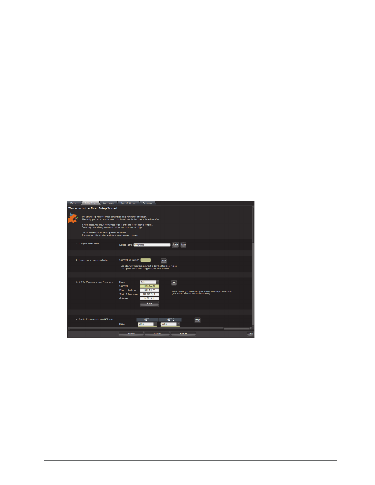
The Newt Setup Wizard is displayed when the Initial Setup tab is selected in DashBoard. (Figure 6.2)
Figure 6.2 Example of the Initial Setup Tab
Use the Newt Setup Wizard to configure the following settings:
• IP Address for the CONTROL port
• IP Address for each NET port
• Licensed features
• Operational Mode
• System Frame Rate
NEWT-IPX User Guide (v4.0) Getting Started • 29
Page 30

• PTP Timing System
•Senders
These steps are further described in the proceeding chapters.
Accessing the NEWT-IPX Interfaces in DashBoard
The NEWT-IPX groups the configuration, monitoring, and operating features as a series of tabs in the DashBoard
client window. Each tab provides access to specific configuration options for your NEWT-IPX.
The interfaces are accessed by double-clicking the NEWT-IPX node in the DashBoard Tree View. This procedure
assumes that you have launched DashBoard on your computer and a valid IP Address is assigned to the
NEWT-IPX.
To access the NEWT-IPX interfaces in DashBoard
1. In the Basic Tree View of DashBoard, expand the top NEWT-IPX node.
2. Expand the NEWT sub-node.
3. Double-click the second NEWT sub-node to display the NEWT-IPX interface in the right pane of the
DashBoard window.
When first accessing the NEWT-IPX interface, the Welcome tab is automatically displayed in DashBoard.
Once the initial settings are configured and applied to the NEWT-IPX, you can hide the Welcome and Initial
Setup tabs by selecting the Initial Setup tab and the Hide Welcome tab and/or Hide Initial Setup Wizard tab
options. You must then click
setting(s).
30 • Getting Started NEWT-IPX User Guide (v4.0)
Refresh (located at the bottom of the DashBoard window) to apply the new
Page 31
Configuring the Ethernet Settings
The NEWT-IPX provides two NET ports that can be populated with Ethernet fiber-optic connectors. The chassis
also provides one Ethernet RJ45 (CONTROL) port that is used to connect to your facility network for DashBoard
communication. This chapter outlines how to configure each of these ports.
Contact your network administrator if difficulties or problems are experienced when assigning IP addresses.
Configuring the CONTROL Port
The CONTROL port is located on the left side of the NEWT-IPX chassis. Once the NEWT-IPX is communicating
via DashBoard, you may wish to assign a different static IP Address from the factory default value (which was used
to initially establish a connection point to the NEWT-IPX).
To assign the initial network settings for the NEWT-IPX
1. Display the NEWT-IPX interfaces in DashBoard as outlined in the procedure “To access the NEWT-IPX
interfaces in DashBoard” on page 30.
2. Select the Initial Setup tab.
You can also change these settings via the Advanced > Ethernet I/O tab.
3. Locate the menus for the CONTROL port.
4. Use the Mode menu to select Static.
5. Use the Static IP Address field to assign a unique IP Address to the NEWT-IPX.
6. Use the Static Subnet Mask field to assign the subnet mask for the NEWT-IPX.
Use the Advanced > Ethernet I/O > Gateway field to specify the gateway for communications outside of the
local area network (LAN) the NEWT-IPX will use.
7. Click
8. Click
9. Verify the new network settings reported on the Advanced > Ethernet I/O tab.
NEWT-IPX User Guide (v4.0) Configuring the Ethernet Settings • 31
Apply.
Reboot to apply the new settings. This button is located at the bottom of the interface.
The NEWT-IPX is temporarily taken off-line during the reboot.
Page 32

Configuring the NET Ports
By assigning an IP Address to each NET port (NET 1, NET 2), you are able to uniquely identify it on the network
and control it via the DashBoard interface. Each NET port can be configured for media traffic for the NEWT-IPX.
This section outlines how to configure the network settings for the NET ports on the chassis.
For More Information on...
• the NET designations, refer to the section “Communications Overview” on page 17.
To update the network settings for a NET port
1. Display the NEWT-IPX interfaces in DashBoard as outlined in the procedure “To access the NEWT-IPX
interfaces in DashBoard” on page 30.
2. Select the Initial Setup tab.
You can also change these settings via the Advanced > Ethernet I/O tab.
3. Locate the options for the NET port you wish to configure.
4. If you are manually configuring the Ethernet settings:
a. Use the Mode menu to select Static.
b. Use the Static IP Address field to specify the new static IP Address for the NEWT-IPX. This is the IP
Address that is used to control and communicate with the specific NET port.
c. Use the Subnet Mask field to specify the subnet mask for the NET port.
d. Use the Gateway field to specify the gateway for communications outside of the local area network (LAN)
the NEWT-IPX will use.
Use the Advanced > Ethernet I/O > Gateway field to specify the gateway for the NET port.
5. If you want the network settings for the NET port to be automatically obtained, and DHCP service is available
on your control network, select DHCP from the Mode menu.
6. Click
7. Repeat this procedure for the second NET port you wish to configure.
8. Click
9. Verify the new settings reported on the Advanced > Ethernet I/O tab.
Apply to save the new settings.
Reboot to apply the new settings. This button is located at the bottom of the interface.
The NEWT-IPX is temporarily taken off-line during the reboot.
32 • Configuring the Ethernet Settings NEWT-IPX User Guide (v4.0)
Page 33
Licensed Features
The NEWT-IPX has software licenses for enabling functions and features of the module. This chapter outlines the
available software licensed features, and how to install a software key for a licensed feature.
License Keys Overview
Tab le 8 .1 provides a brief summary on the types of licensed features available for the NEWT-IPX.
Table 8.1 List of NEWT-IPX Licensed Features
License Description
NEWT-IPR-3G-4S IP to 4x3G-SDI gateway
NEWT-IPR-UHD-H UHD-over-IP to HDMI 2.0 gateway
NEWT-IPX-3G-4S 2-in/2-out SDI/IP Converter
Installing a License Key
Ross Video uses license keys to control user access to specific NEWT-IPX features. You can obtain a key for an
NEWT-IPX licensed feature from Ross Video Technical Support.
To install an NEWT-IPX license key
1. Display the NEWT-IPX interfaces in DashBoard as outlined in the procedure “To access the NEWT-IPX
interfaces in DashBoard” on page 30.
2. Select the Initial Setup tab.
You can also change these settings via the Advanced > Licensing tab.
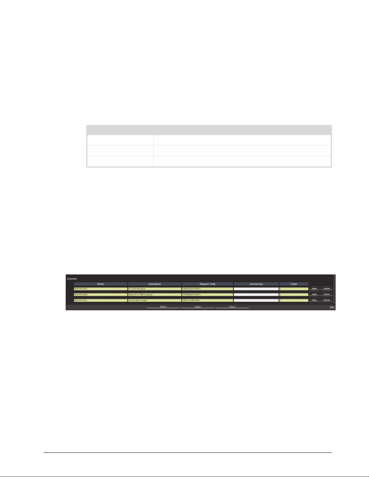
3. Scroll down the tab to display the Licenses table.
4. Make a note of the character string in the Request Code field for the feature you wish to enable.
5. Contact Ross Video Technical Support using the information found in the section “Contacting Technical
Support” on page 12.
a. When you speak to your Technical Support representative, tell them your name, your facility name, and the
Request Code from the Licenses table.
b. You will be given a License Key that must be entered in the applicable field in the Licenses table.
6. Enter the provided License Key in the applicable License Key field in the Licenses table.
7. Click
Apply in the row for the License Key you entered in step 6.
8. Verify that the Count field is updated to report each installed License Key.
NEWT-IPX User Guide (v4.0) Licensed Features • 33
Page 34

Removing a License Key
Disabling a License Key removes user access to the NEWT-IPX features associated with that License Key.
To remove a NEWT-IPX license key
1. Display the NEWT-IPX interfaces in DashBoard as outlined in the procedure “To access the NEWT-IPX
interfaces in DashBoard” on page 30.
2. Select Advanced > Licensing.
3. If required, scroll to the Licenses table.
4. Click in the field for the licensed feature you want to uninstall.
5. Type
6. Click
remove.
Apply to remove the license.
34 • Licensed Features NEWT-IPX User Guide (v4.0)
Page 35
Protocol Setup
This chapter outlines how to specify which outputs to enable on the NEWT-IPX, enable the Protection Switching
feature, and configure the NEWT-IPX for a specific media distribution protocol.
Specifying an Operational Mode
Before proceeding to configure your NEWT-IPX, you must first specify the Operational Mode for the module. This
will determine the number of receivers to configure and the type of outputs available (SDI or HDMI).
To specify an operational mode for the NEWT-IPX
1. Display the NEWT-IPX interfaces in DashBoard as outlined in the procedure “To access the NEWT-IPX
interfaces in DashBoard” on page 30.
2. Select the Initial Setup tab.
You can also change these settings via the Advanced > Device Setup tab.
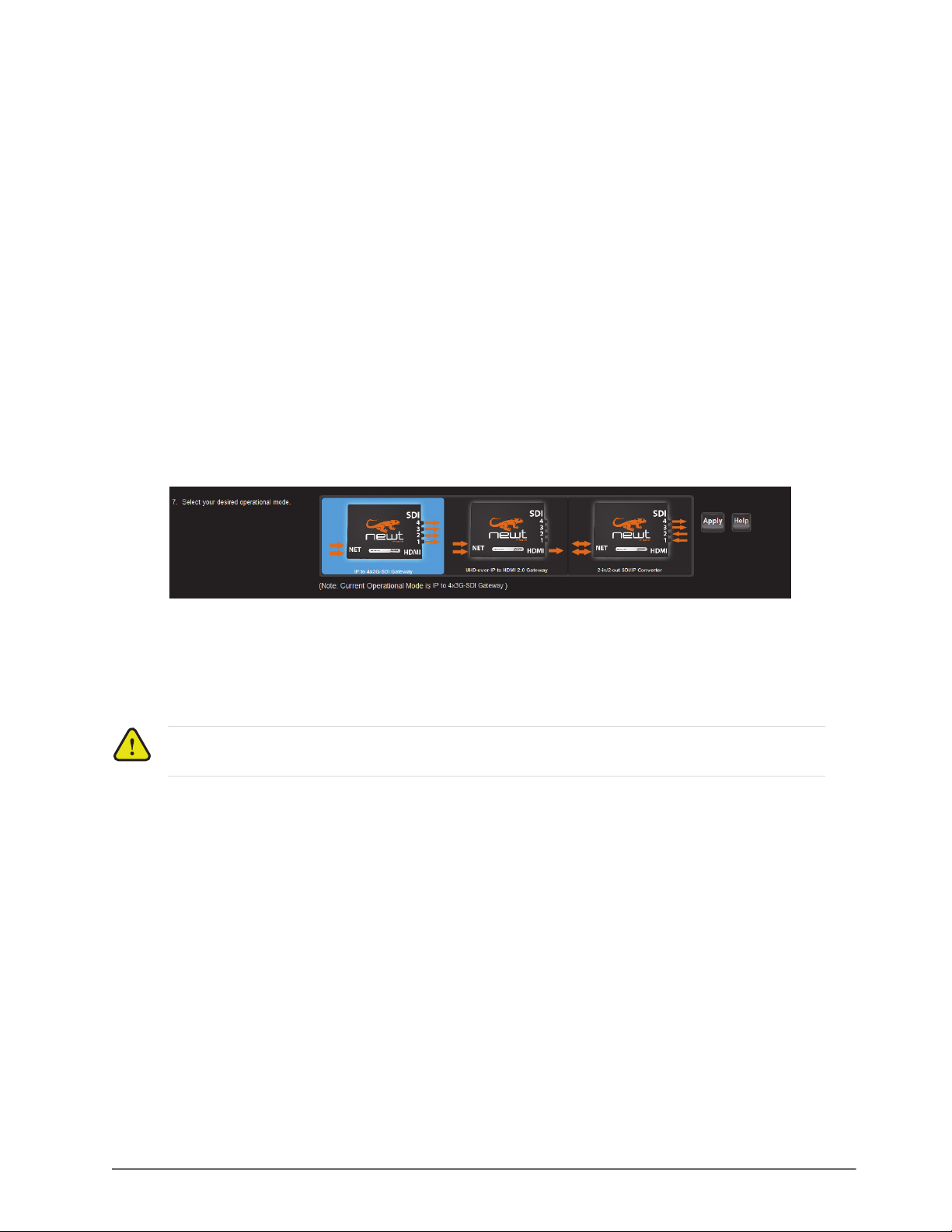
3. Locate the Select your desired operational mode buttons. You may need to scroll to the bottom of the tab to
access these buttons.
4. Select the required mode button.
If the mode button displays a red Lock icon, a license key is not installed to enable that mode. Refer to the
chapter “Licensed Features” on page 33 for details on installing a license key.
5. Click
6. Monitor the automatic NEWT-IPX reboot process.
Apply.
Notice — Do not power down the NEWT-IPX during this procedure. Doing so may set the NEWT-IPX
into a non-operational state.
Setting up Protection Switching
The NEWT-IPX enables a user to protect their streams to ensure mission critical operation. Using SMPTE ST
2022-7 they can run the same video and audio over two separate, redundant networks in case an error occurs with
any hardware.
This section is only applicable if your system requires protection switching.
Before You Begin
Ensure that:
• your source is capable of sending SMPTE ST 2022-7 streams
• the NEWT-IPX is set up with a protection switching network
NEWT-IPX User Guide (v4.0) Protocol Setup • 35
Page 36

Enabling the Protection Switching Feature
By default, the SMPTE ST 2022-7 Protection Switching feature is disabled. Once enabled, the Receivers, Senders1,
and Network Streams tabs update to include options for configuring the Protection Switching streams.
This feature is reset when the Load Factory Defaults button is selected.
To enable the Protection Switching feature
1. Display the NEWT-IPX interfaces in DashBoard as outlined in the procedure “To access the NEWT-IPX
interfaces in DashBoard” on page 30.
2. Select Advanced > Device Setup.
3. Select the SMPTE ST 2022-7/Seamless Protection Switching box.
4. Click
5. Click
6. Click
7. Monitor the reboot progress.
OK in the prompt confirming that all sessions will be removed.
Apply.
Reboot to apply the new settings. This button is located at the bottom of the interface.
The NEWT-IPX is temporarily taken off-line during the reboot.
Configuring the NEWT-IPX for Protection Switching
You will need to assign a unique IP address to each video stream (e.g. primary 239.1.1.1, secondary IP 239.1.1.2).
The audio streams must have the same IP address as the video streams.
To configure the NEWT-IPX for protection switching
1. Configure the primary and secondary Receiver streams as outlined in “Configuring a Receiver” on page 43.
The UDP value can be the same or different for the primary and secondary streams.
2. Configure the primary and secondary Network streams as outlined in “Adding a Network Stream” on
page 51.
3. Click
4. Monitor the reboot progress.
Reboot. This button is located on the bottom of the interface.
Registration and Discovery
The NEWT-IPX supports media distribution based on RAVENNA, RTSP, NMOS, and Ember+. This section
outlines how to configure the NEWT-IPX for each protocol.
RAVENNA Support
This section outlines how to configure the NEWT-IPX for the open standard for real-time media over IP (AES67).
To configure the NEWT-IPX as a RAVENNA device
1. Display the NEWT-IPX interfaces in DashBoard as outlined in the procedure “To access the NEWT-IPX
interfaces in DashBoard” on page 30.
2. Select Advanced > Discovery.
1. If operating in 2in/2out mode.
36 • Protocol Setup NEWT-IPX User Guide (v4.0)
Page 37

3. Locate the RAVENNA area in the tab.
4. To re-name the NEWT-IPX for the RAVENNA network, perform one of the following:
• Use the Board Name menu to specify a unique identifier for the NEWT-IPX in the RAVENNA network; or
•Click
Use System Device Name.
5. Use the Interface menu to specify what physical port the NEWT-IPX uses for RAVENNA communications.
6. Use the Port menu to specify the port assigned to the NEWT-IPX within the RAV E N N A n e t w o r k .
7. Click
8. Click
Apply to save the new settings.
Reboot to apply the new settings. This button is located at the bottom of the interface.
The NEWT-IPX is temporarily taken off-line during the reboot.
9. Monitor the reboot progress.
RTSP Support
This section outlines the required settings when establishing communications between NEWT-IPX and an external
device via the Real Time Streaming Protocol (RTSP).
To configure the NEWT-IPX as a RTSP device
1. Display the NEWT-IPX interfaces in DashBoard as outlined in the procedure “To access the NEWT-IPX
interfaces in DashBoard” on page 30.
2. Select Advanced > Discovery.
3. Locate the RTSP area in the tab.
4. Use the Interface menu to specify what physical port the NEWT-IPX uses for RTSP communications.
5. Use the Port field to specify the TCP port the protocol sues to send and receive messages.
6. Click
7. Click
Apply to save the new settings.
Reboot to apply the new settings. This button is located at the bottom of the interface.
The NEWT-IPX is temporarily taken off-line during the reboot.
8. Monitor the reboot progress.
NEWT-IPX User Guide (v4.0) Protocol Setup • 37
Page 38

Ember+ Support
To establish a connection between the Ember+ client and the NEWT-IPX you will need to:
1. Add the NEWT-IPX in the Ember+ client interface using the IP Address assigned to the NEWT-IPX.
2. Enable SDP patching with the Ember+ client to establish video and audio receivers on the NEWT-IPX.
3. Set the TCP port to 9095, in the Ember+ client, for the NEWT-IPX.
SAP Support
This section outlines how to enable the NEWT-IPX to use the Session Announcement Protocol (SAP) when
broadcasting multicast session information.
To configure the NEWT-IPX to use SAP for multicast broadcasting
1. Display the NEWT-IPX interfaces in DashBoard as outlined in the procedure “To access the NEWT-IPX
interfaces in DashBoard” on page 30.
2. Select Advanced > Discovery.
3. Locate the SAP area in the tab.
4. Select the Enable box.
5. Click
6. Click
Apply to save the new settings.
Reboot to apply the new settings. This button is located at the bottom of the interface.
The NEWT-IPX is temporarily taken off-line during the reboot.
7. Monitor the reboot progress.
NMOS Support
This section outlines the required settings on the NEWT-IPX to establish communications via the Network Media
Open Specifications (NMOS).
To configure the NEWT-IPX as a NMOS device
1. Display the NEWT-IPX interfaces in DashBoard as outlined in the procedure “To access the NEWT-IPX
interfaces in DashBoard” on page 30.
2. Select Advanced > Discovery.
3. Locate the NMOS area in the tab.
4. To assign a name to the NEWT-IPX for use in the NMOS network, perform one of the following:
• Use the Device Name menu to specify a unique identifier for the NEWT-IPX in the NMOS network; or
•Click
5. Use the Interface menu to specify what physical port the NEWT-IPX uses for NMOS communications.
6. Use the Node Port field to specify the HTTP port used by the NEWT-IPX to browse NMOS properties.
Use System Device Name.
7. Use the SDP Port field to specify the SDP HTTP port used to GET SDPS.
8. Select the Enable box.
9. Click
10. Click
Apply to save the new settings.
Reboot. This button is located on the bottom of the interface.
11. Monitor the reboot progress.
38 • Protocol Setup NEWT-IPX User Guide (v4.0)
Page 39

Configuring the Timing Settings
The NEWT-IPX supports the Precision Time Protocol (PTP) as defined in the IEEE 1588-2008 standard and the
SMPTE ST 2059 specification.
Specifying a Reference Format Rate
NEWT-IPX requires a PTP master on the media network to drive its timing. By default, the NEWT-IPX is
configured to run as a PTP slave. If there is no lock to PTP, the NEWT-IPX will not receive IP streams.
You can also change the System Frame Rate via the Advanced > Device Setup tab.
To specify a frame rate for the NEWT-IPX video signals
1. Display the NEWT-IPX interfaces in DashBoard as outlined in the procedure “To access the NEWT-IPX
interfaces in DashBoard” on page 30.
2. Select the Initial Setup tab.
3. Use the System Frame Rate menu to specify a video frame rate that is compatible with the SDI signals that the
NEWT-IPX will output.
4. Click
5. Click
Apply to save the new setting.
Reboot to apply the new setting.
The System Frame Rate setting will not be applied until the PTP is locked.
Configuring the PTP Settings
From the Timing tab in DashBoard, you can synchronize the NEWT-IPX to real-time clocks of other devices in the
same network.
There are several criteria that PTP clocks compare to determine who will be master and who will be slave (called
the Best Master Clock Algorithm, or BMCA), and they are evaluated in order: Priority1, clock class, accuracy,
scaled log variance, Priority2, clock ID (similar to the MAC address). Practically, Priority1 is the only setting
configured on all clocks to control the outcome of the Grandmaster election. If Priority1s are equal, the next
criterion is evaluated (clock class) and the criteria are evaluated in succession until a Grandmaster is determined.
To update the PTP settings for the NEWT-IPX
1. Display the NEWT-IPX interfaces in DashBoard as outlined in the procedure “To access the NEWT-IPX
interfaces in DashBoard” on page 30.
2. Select the Initial Setup tab.
You can also change these settings via the Advanced > Timing > PTP tab.
3. Locate the Configure PTP Timing System area of the Initial Setup tab.
4. Select the Slave Only box to define the NEWT-IPX as only a slave and never a Boundary Clock or
Grandmaster device.
5. Select the Custom PTP Profile box.
NEWT-IPX User Guide (v4.0) Configuring the Timing Settings • 39
Page 40
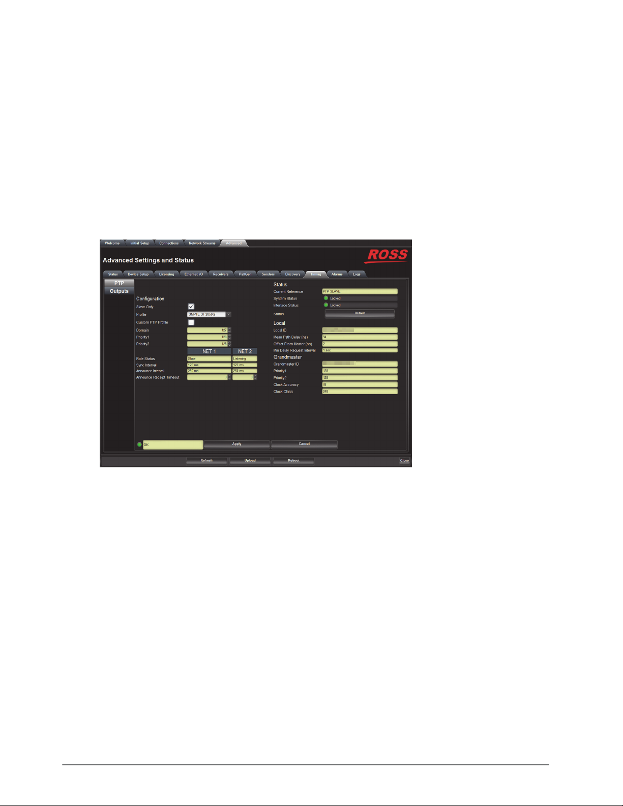
6. Use the Domain field to specify the sub-domain the PTP clock is assigned to.
There can be multiple PTP domains operating concurrently within a network. The domain is a field in all PTP
message headers. Messaging between entities are segregated by domain (e.g. The NEWT-IPX is an endpoint
configured for domain 128 and ignores messages from a neighboring clock configured for domain 127).
7. If you did not select the Slave Only box and the NEWT-IPX matches the primary Grandmaster election
criterion for your network:
a. Use the Priority 1 field to define the first 8bit clock field.
b. Use the Priority 2 field to define the backup 8bit clock field.
To configure the PTP settings for a specific NET port
1. Select Advanced > Timing.
The PTP tab is automatically selected.
2. Select the Custom PTP Profile check box.
The Domain, Priority1, Priority2, Sync Interval, Announce Interval and Announce Receipt Timeout fields are
now editable.
The Custom PTP Profile can also be set using the Initial Setup tab.
3. Use the Sync Interval field to specify the number of seconds at which synchronization messages are sent from
the master clock to the specified NET port on the NEWT-IPX.
4. Use the Announce Interval field to specify the rate of announce messages that the specified NET port on the
NEWT-IPX requests from the master clock during a unicast session.
5. Use the Announce Receipt Timeout field to specify the number of seconds the specified NET port on the
NEWT-IPX waits for an announce interval message before timing out.
6. Click
Apply to save the new settings.
Configuring the Video Delay and Audio Offset for Outputs
An output is timed relative to the input stream, and the source will be delayed a fixed offset from the sender’s RTP
timestamps. This allows for non-PTP aligned sources to be passed through with fixed latency.
40 • Configuring the Timing Settings NEWT-IPX User Guide (v4.0)
Page 41
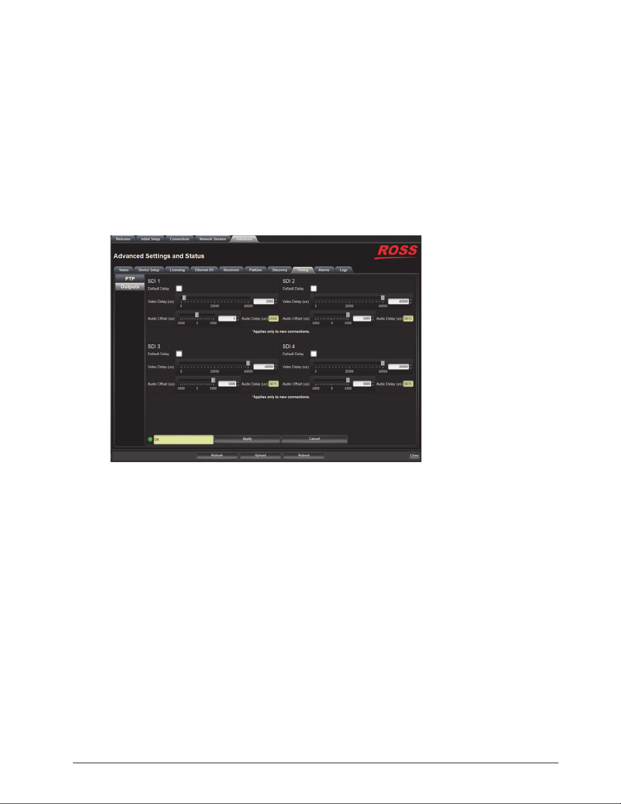
Use this procedure if you need to adjust the timing of each output independently. Otherwise it is recommended to
keep these settings at the default values.
To adjust the timing for an output
1. Display the NEWT-IPX interfaces in DashBoard as outlined in the procedure “To access the NEWT-IPX
interfaces in DashBoard” on page 30.
2. Select Advanced > Timing.
3. Click
Outputs.
The Timing tab updates to display the timing options for each output. In the following example, there are four
SDI outputs available for adjustment.
The number and type of available outputs depends on the Operational Mode the NEWT-IPX is set to. Refer to the
section “Specifying an Operational Mode” on page 35 for details.
4. Locate the options for the output you want to adjust the timing for.
5. To automatically apply the default delay value of 6000us, select the Default Delay box for the output.
6. To manually configure the delay and offset values for an output:
a. Verify that the Default Delay box is cleared.
b. Use the Video Delay slider to adjust the relative position of the video output start of frame as an offset to
the reference.
c. Use the Audio Offset slider to adjust the relative position of the audio start position as an offset to the
reference.
Audio delay is specified relative to the video timing.
7. Click
8. Refresh the connection.
Apply to save the new settings.
To re-establish connections, proceed to the section “Operation” on page 55.
NEWT-IPX User Guide (v4.0) Configuring the Timing Settings • 41
Page 42

Setting the Audio Packet Time
You can add an offset to the audio streams if you wish to define the rate that the NEWT-IPX sends packets. Keep in
mind that a smaller packet time results in more Ethernet packet overhead (more packets are sent) but less network
delay.
This impacts all connected audio streams. Applying a new Audio Packet Time automatically disconnects and
re-connects all audio streams. It is recommended to set the Audio Packet Time before configuring your audio
streams.
To set the audio packet time
1. Display the NEWT-IPX interfaces in DashBoard as outlined in the procedure “To access the NEWT-IPX
interfaces in DashBoard” on page 30.
2. Select the Advanced > Device Setup.
3. Use the Audio Packet Time menu to specify the amount of time that NEWT-IPX will add as an offset to the
audio streams.
4. Click
5. Verify that the audio streams have re-connected by viewing their status:
Apply.
a. Select the Connections tab.
b. Locate the audio streams row in the Destinations area of the tab.
c. Verify the read-only fields display “
d. If the audio streams do not automatically connect, navigate to the Receivers tab and verify the settings for
the audio streams.
Connection was Successful”.
42 • Configuring the Timing Settings NEWT-IPX User Guide (v4.0)
Page 43
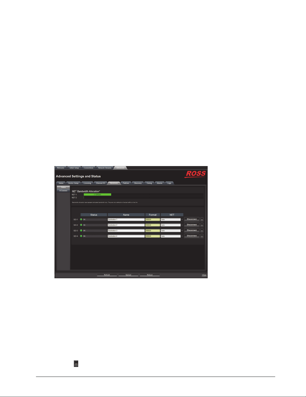
Configuring the Receivers
Once you configure your Network Stream groups, you can connect each Network Stream to a Receiver using the
options in the Connections tab.
For More Information on...
• specifying the network stream groups, refer to the chapter “Setting up the Network Streams” on page 51.
• the assigning of a Receiver to a Stream, refer to the chapter “Operation” on page 53.
Configuring a Receiver
Each configured Receiver enables the NEWT-IPX to advertise to Senders how much data it can receive and buffer.
The number and type of available outputs depends on the Operational Mode the NEWT-IPX is set to. Refer to the
section “Specifying an Operational Mode” on page 35 for details.
To name a receiver
1. Display the NEWT-IPX interfaces in DashBoard as outlined in the procedure “To access the NEWT-IPX
interfaces in DashBoard” on page 30.
2. Select Advanced > Receivers.
3. Locate the row for the SDI signal you wish to configure.
4. Use the Name field to specify a unique identifier for the receiver.
This identifier is used to help identify the receiver within your system and in the DashBoard Connections
interface.
To assign a NET port to a receiver
1. Display the NEWT-IPX interfaces in DashBoard as outlined in the procedure “To access the NEWT-IPX
interfaces in DashBoard” on page 30.
2. Select Advanced > Receivers.
3. Use the NET menu to assign the SDI signal to an NET port connection on the NEWT-IPX.
4. Click the
NEWT-IPX User Guide (v4.0) Configuring the Receivers • 43
button to expand the monitoring options for the SDI signal.
Page 44
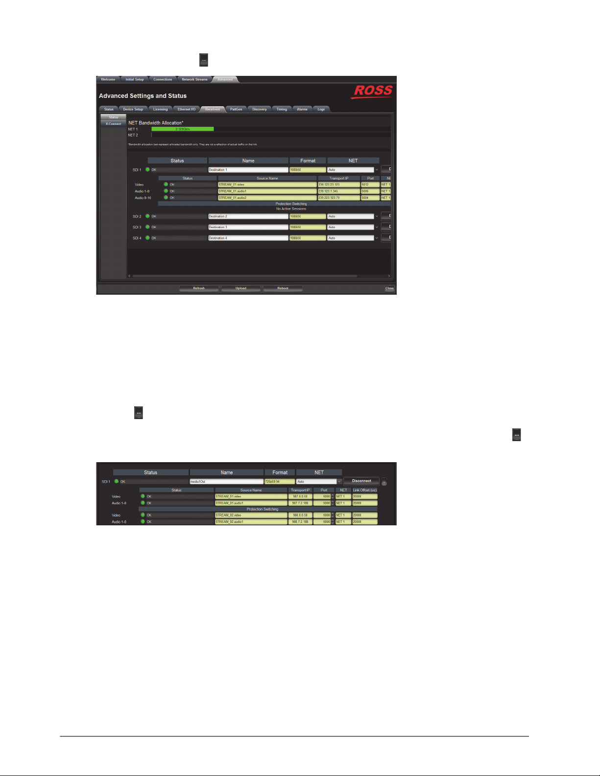
In the example below, the button was selected for SDI 1.
5. Verify the source(s) for the SDI are correct and no errors are reported.
To verify the protection switching feature
1. Ensure the ST 2022-7/Seamless Protection Switching box is selected as outlined in the section “Enabling the
Protection Switching Feature” on page 36.
2. Select Advanced > Receivers.
3. Locate the row for the SDI signal you wish to configure for protection switching.
4. Click the
The Protection Switching options display as two separate rows under the SDI. In the example below, the
button was selected for SDI 1.
button to expand the options.
Protection switching streams are assigned when a connection is made in the Connections tab. Refer to the
section “Routing the Signals” on page 56 for more information.
Assigning a Test Pattern to the SDI Output
You can specify the type of internally generated test pattern to output.
The number of SDI outputs available depends on the Operational Mode. Refer to the section “Specifying an
Operational Mode” on page 35 for details.
To assign a test pattern to an SDI output
1. Display the NEWT-IPX interfaces in DashBoard as outlined in the procedure “To access the NEWT-IPX
interfaces in DashBoard” on page 30.
2. Select Advanced > PattGen.
44 • Configuring the Receivers NEWT-IPX User Guide (v4.0)
Page 45
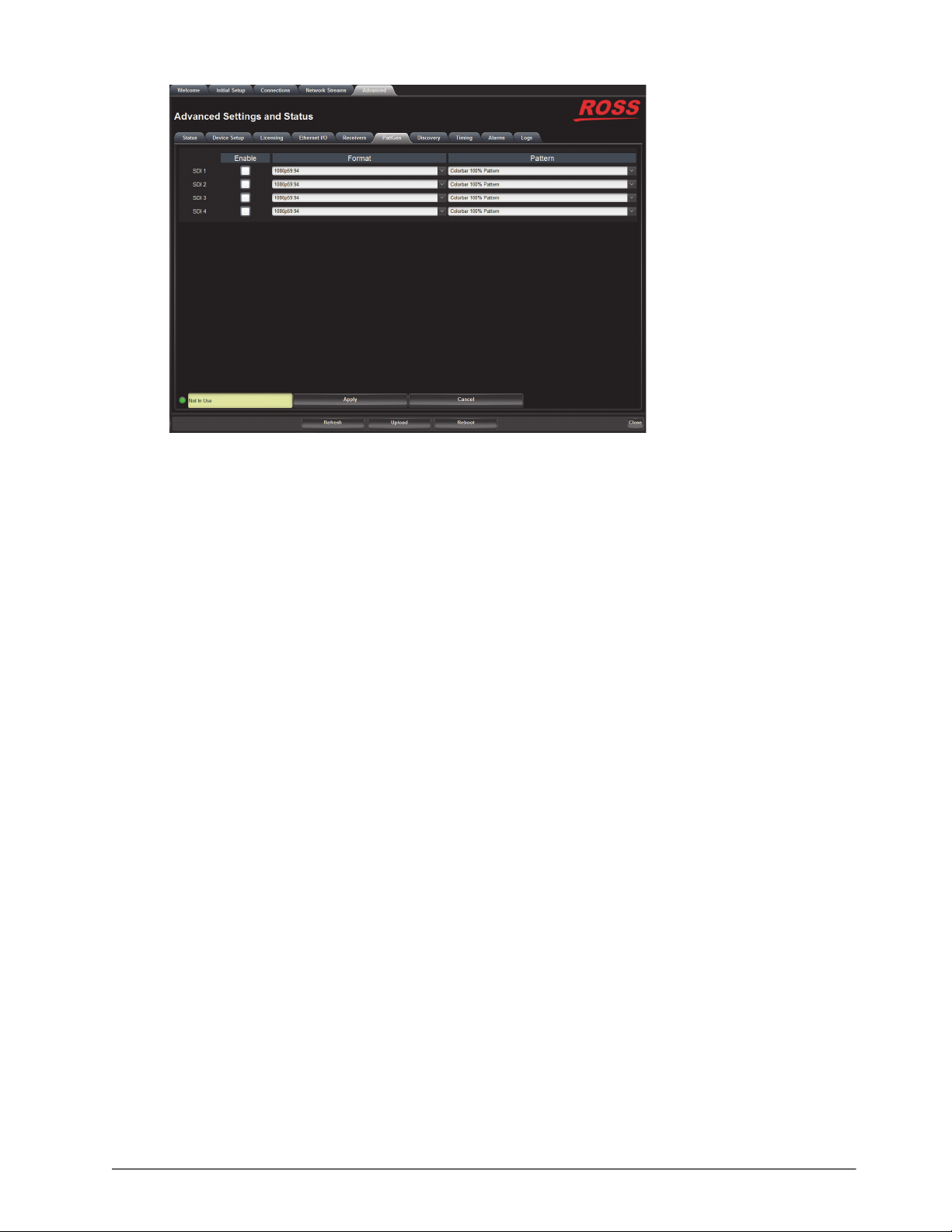
3. Locate the row for the SDI signal you wish to output a test pattern on.
4. Use the Format menu to specify the video format for the test pattern output.
5. Use the Pattern menu to specify the pattern to display on the output.
6. Select the Enable box to allow the SDI connection to output the test pattern.
7. Click
Apply to save the new settings.
Using the Disconnect Button
Clicking the Disconnect button for a session immediately stops that session and outputs black. This is helpful:
• to free up NET bandwidth
• if the source is invalid or missing
• if the source includes data that you do not want to output
• to update the receiver with the latest NET settings
You will need to return to the Connections tab to reconnect the sessions.
NEWT-IPX User Guide (v4.0) Configuring the Receivers • 45
Page 46

46 • Configuring the Receivers NEWT-IPX User Guide (v4.0)
Page 47
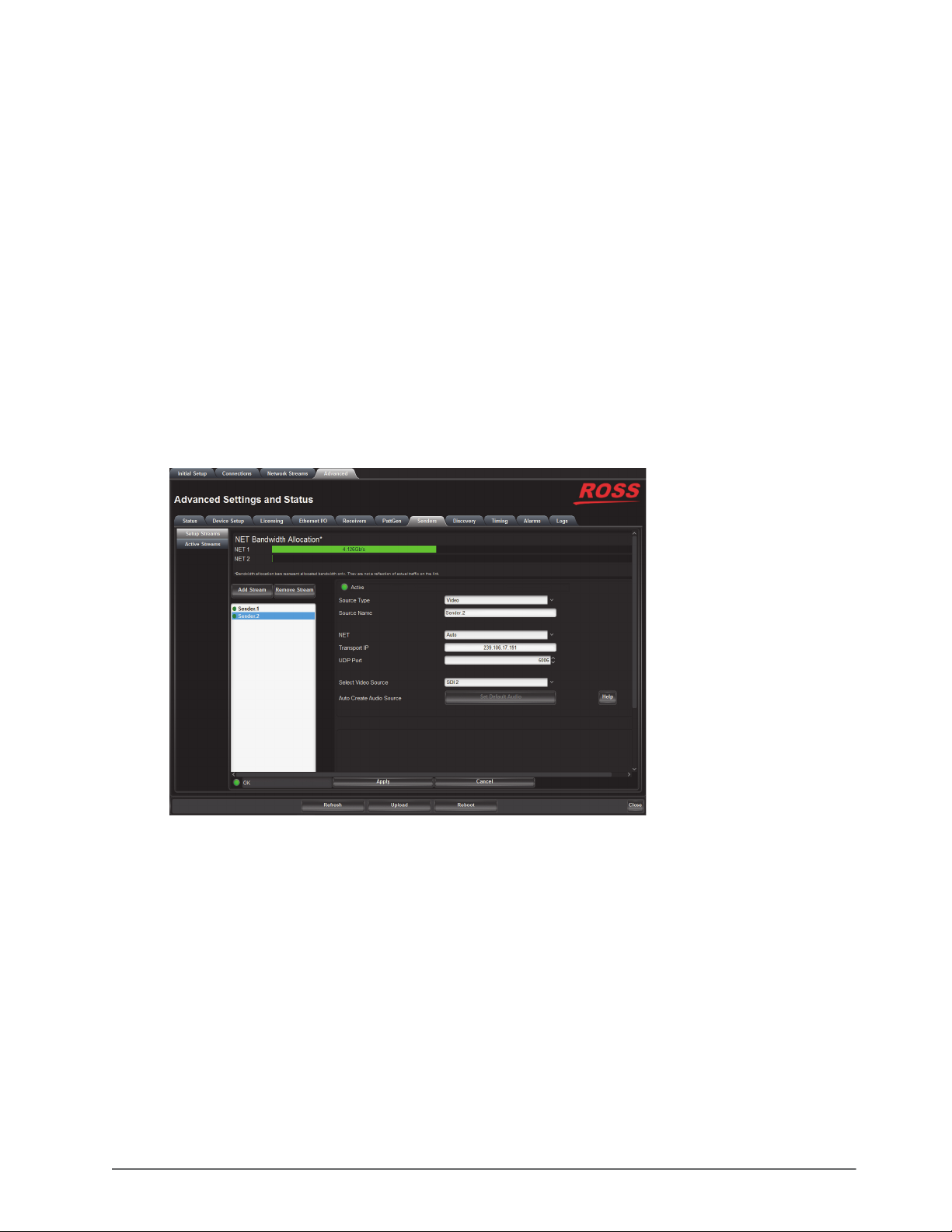
Configuring the Senders
For each SDI input signal, you need to specify the IP encapsulation properties for the active video and audio.
The NEWT-IPX must be configured as an 2-in/2-out SDI/IP Converter. Refer to the section “Installing a
License Key” on page 33 and “Specifying an Operational Mode” on page 35 for details.
Configuring the Active Video Properties
Before you begin, make a note of the NET Bandwidth Allocation for the NET ports to determine the available
capacity on each port. This information is displayed in the top portion of the Senders tab.
To configure the active video properties for a sender stream
1. Display the NEWT-IPX interfaces in DashBoard as outlined in the procedure “To access the NEWT-IPX
interfaces in DashBoard” on page 30.
2. Select Advanced > Senders.
The Setup Streams sub-tab is automatically selected.
3. Click
4. Use the Source Type menu to select Video.
5. Use the Source Name field to assign a unique identifier for the stream.
Add Stream.
The Stream list and Source Name field updates to include a new entry “
auto-generated number.
Sender #” where # is an
The Source Name is used to help identify the sender within your system and in the DashBoard Connections
interface.
6. Use the NET menu to select the network interface used to transmit the data stream to the selected NET port on
the NEWT-IPX chassis.
7. Edit the Transport IP and UDP Port fields for the Primary Stream you wish to assign the sender to.
It is recommended to not edit the Transport IP and UDP Port fields as these fields are auto-populated by the
advertised stream.
NEWT-IPX User Guide (v4.0) Configuring the Senders • 47
Page 48

8. If required, edit the Transport IP and UDP Port fields for the Protection Switching stream the sender will use.
9. Use the Select Video Source menu to assign the SDI input signal to the sender stream.
10. Click
Apply to save the new settings.
Configuring the Active Audio Properties
Before you begin, make a note of the NET Bandwidth Allocation for the NET ports to determine the available
capacity on each port. This information is displayed in the top portion of the Senders tab.
Creating an Audio Stream Group
You can map the audio channels to a stream as required: using the default map of 1:1 or selecting specific channels
and assigning them in any given order. This enables you to customize each audio stream group to include any
available audio channels.
To configure the active audio properties for a sender stream
1. Display the NEWT-IPX interfaces in DashBoard as outlined in the procedure “To access the NEWT-IPX
interfaces in DashBoard” on page 30.
2. Select Advanced > Senders.
The Setup Streams sub-tab is automatically selected.
3. Click
4. Use the Source Type menu to select Audio.
5. Use the Source Name field to assign a unique identifier for the stream.
Add Stream.
This identifier is used to help identify the sender within your system and in the DashBoard Connections
interface.
6. Edit the Transport ID and UDP Port fields for the Primary Stream you wish to assign the sender to.
It is recommended to not edit the Transport ID and UDP Port fields as these fields are auto-populated by the
advertised stream.
7. If required, edit the Transport ID and UDP Port fields for the Protection Switching stream the sender will use.
8. If you need to map the audio channels to this new stream, proceed to “Mapping the Audio Channels to a
Sender Stream” on page 48.
9. Click
Apply to save the new settings.
Mapping the Audio Channels to a Sender Stream
You can choose to apply the default audio channel map or assign the channels as required by your system. Both
methods are described below.
To map the audio channels to a sender stream using the default channel map
1. Create a new audio stream as outlined in the section “Creating an Audio Stream Group” on page 48.
2. Click
3. Click
Set Default Audio.
The SDI Channels map updates to display the default channel options.
Apply to save the new settings.
To customize the audio channel mapping for a sender stream
1. In the SDI Channels map, select the channels to include in the audio stream.
In the example below, the user selected channel
48 • Configuring the Senders NEWT-IPX User Guide (v4.0)
B7.
Page 49
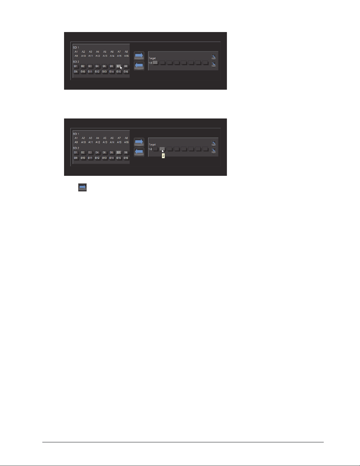
2. In the Ta rg et map, select the sender channel to assign the audio channel to.
In the example below, the user selected Target channel
3. Click .
4. Click
Apply to save the new settings.
2.
NEWT-IPX User Guide (v4.0) Configuring the Senders • 49
Page 50

50 • Configuring the Senders NEWT-IPX User Guide (v4.0)
Page 51
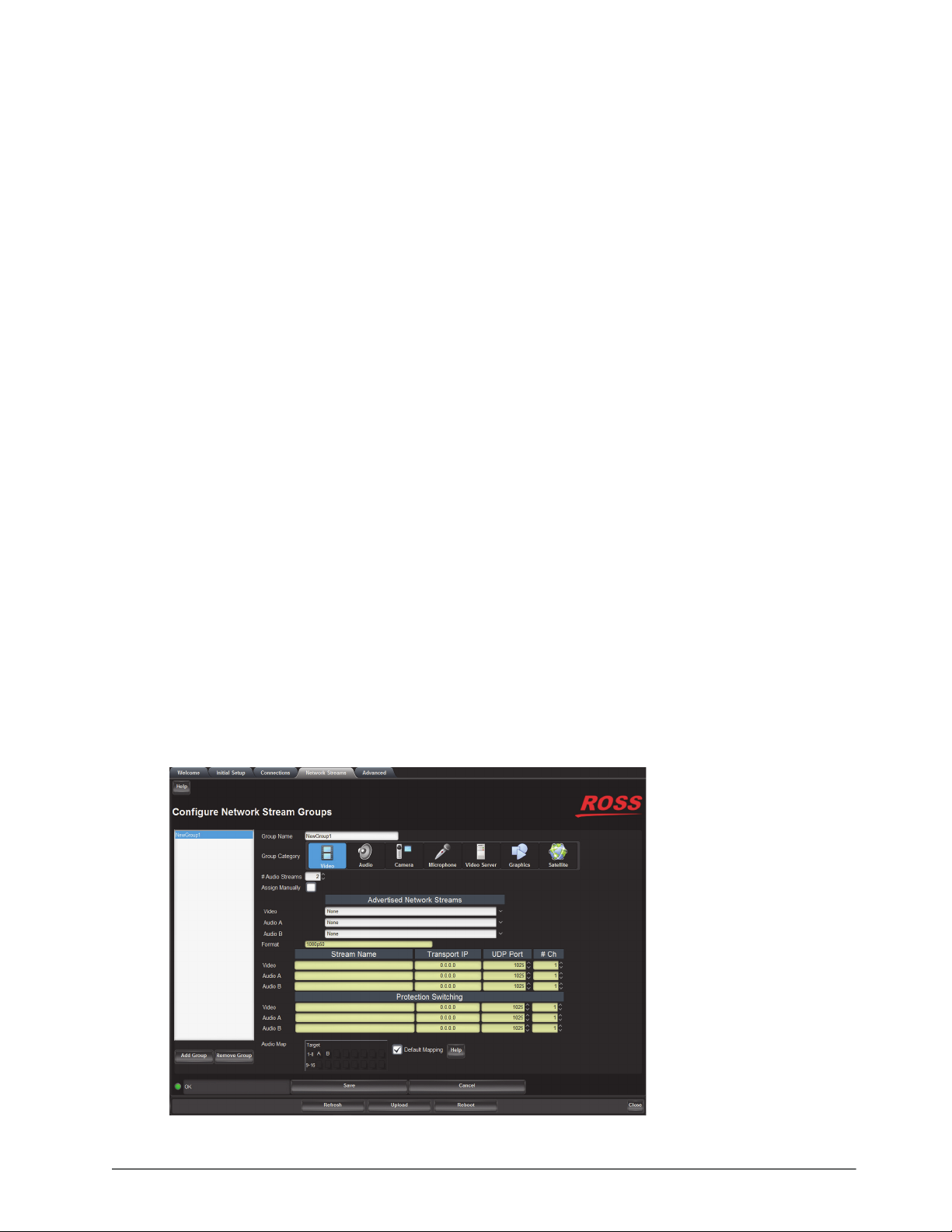
Setting up the Network Streams
Once you have the Receivers configured on the NEWT-IPX, you must specify the available IP streams as network
sessions for the NEWT-IPX.
Overview
You can configure a network stream for the NEWT-IPX by assigning an advertised stream or adding a stream by
manually specifying the IP stream credentials.
Advertised Streams
A network stream advertised by a node flows to multiple devices. The list of advertised RAVENNA streams
available to the NEWT-IPX depends on the following settings:
• Advanced > Timing > PTP
• Advanced > Device Setup > Transport Options
Manually Assigning a Stream
An IP stream can also be manually assigned as a network stream for the NEWT-IPX. You will need the Transport IP
Address, Port number, and DSCP value for the IP stream you want to add. This is useful if you wish to access a
network stream that is not a RAVENNA device.
Adding a Network Stream
A network stream is identified in the Receivers and Connections tabs using the parameters specified in the Network
Streams tab. Ensure to give each network session a unique name for easy identification in the DashBoard interfaces.
To add a new network stream using an advertised stream
1. Display the NEWT-IPX interfaces in DashBoard as outlined in the procedure “To access the NEWT-IPX
interfaces in DashBoard” on page 30.
2. Select the Network Streams tab.
NEWT-IPX User Guide (v4.0) Setting up the Network Streams • 51
Page 52

3. Click Add Group.
The fields in the Network Streams tab clear and the Group Name field displays “
NewGroup#” where # is an
auto-generated character.
4. Use the Group Name field to specify a unique identifier for the network stream.
5. Use the options in the Group Category area to assign the network stream to a Connections category.
6. Use the # Audio Streams box to specify the total number of audio streams for this group.
7. Verify that the Assign Manually box is unselected (cleared).
8. Use the Advertised Network Streams menus to specify the stream for the video and/or audio signals for the
network stream.
The Format, Transport IP, Port, UDP Port, and # Ch fields are read-only and automatically populated when
a new selection is made in the Advertised Network Streams area.
9. Click
To add a new network stream using a manually added stream
Save to update the list in the Network Streams tab.
1. Display the NEWT-IPX interfaces in DashBoard as outlined in the procedure “To access the NEWT-IPX
interfaces in DashBoard” on page 30.
2. Select the Network Streams tab.
3. Click
Add Group.
The fields in the Network Streams tab clear and the Group Name field displays “
NewGroup#” where # is an
auto-generated character.
4. Use the Group Name field to specify a unique identifier for the network session.
5. Use the options in the Group Category area to assign the network stream to a Connections category.
6. Select the Assign Manually box.
The Format, Transport IP, UDP Port, and # Ch fields are now editable.
7. Use the Format field to specify the video format of the signal available for the stream.
8. Use the Transport IP field to specify the Multicast IP Address for the network session.
Only multicast IP Address of 239.x.x.x and 232.x.x.x can be received by the NEWT-IPX. Contact Ross
Technical Support if you need additional IP ranges.
9. Use the UDP Port field to specify the RTP port for the advertised stream.
10. Use the # Ch field to specify the maximum number of audio channels in the specified stream
11. Click
To specify network streams for protection switching
1. Ensure the ST 2022-7/Seamless Protection Switching box is selected as outlined in the section “Enabling the
2. Add a new network stream as outlined in the procedure “To add a new network stream using a manually
3. Use the Protection Switching fields to assign the redundant video and audio streams to the NEWT-IPX.
Save to update the list in the Network Streams tab.
Protection Switching Feature” on page 36.
added stream” on page 52.
The Protection Switching options display as two separate rows.
4. Click
52 • Setting up the Network Streams NEWT-IPX User Guide (v4.0)
Save to update the list in the Network Streams tab.
Page 53
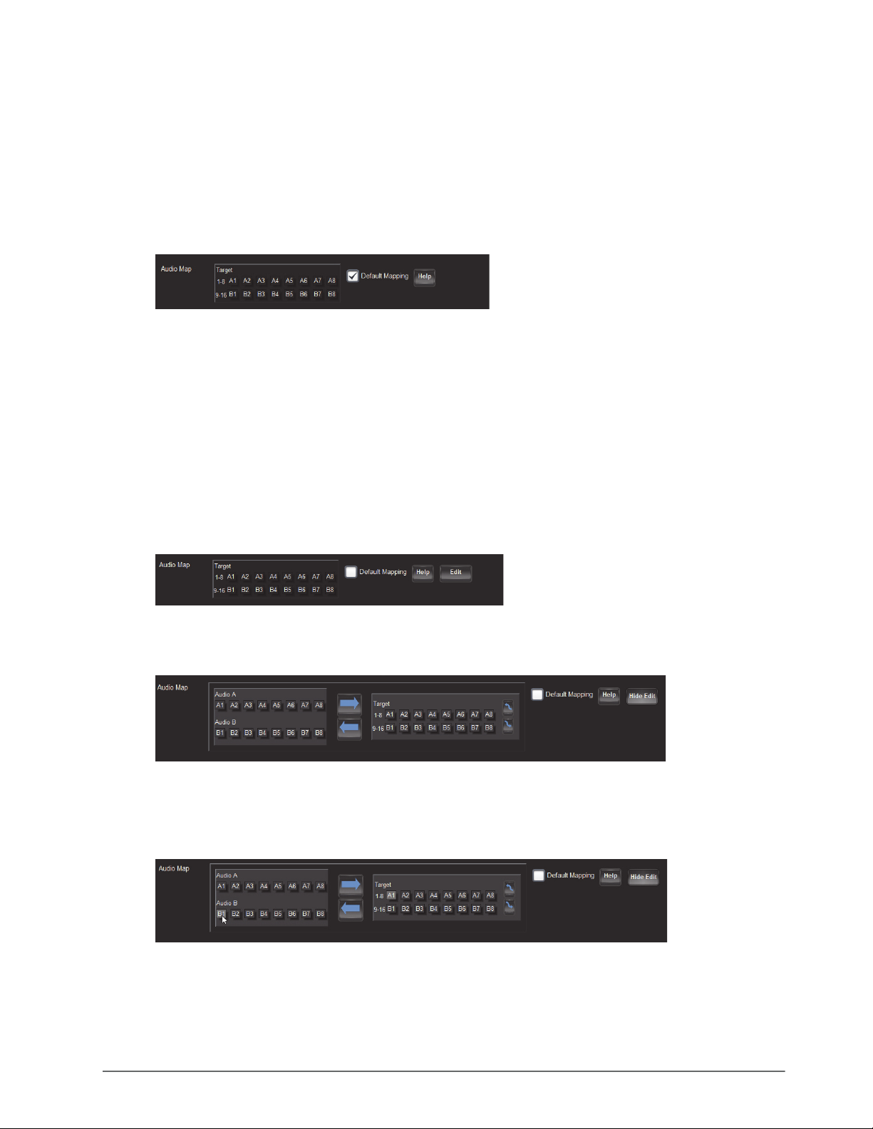
Mapping the Audio Channels
You can choose to apply the default audio channel map or assign the channels as required by your system. Both
methods are described below.
To assign audio channels to a stream using the default map
1. Locate the Audio Map area of the Network Streams tab.
2. Select the Default Mapping box to map the channels to audio streams as 1:1.
In the example below, the # Audio Streams was set to 2.
3. Click
Save to update the list in the Network Streams tab.
You may need to scroll down the tab to locate this button.
To customize the audio channel mapping for the network stream
1. Locate the Audio Map area of the Network Streams tab.
You may need to scroll down the tab to fully display the Audio Map.
2. Clear the Default Mapping box.
The Channel Mapping area updates to display the mapping options based on the number of destinations and
audio channels you specified using the fields on this tab.
The
Edit button now displays.
3. Click
Edit.
The Audio Map area updates to provide two maps.
4. Select the network stream channel(s) on the leftmost map.
You can also select multiple stream channels by clicking and dragging the audio channels.
The following example, the user selected
NEWT-IPX User Guide (v4.0) Setting up the Network Streams • 53
B1.
Page 54
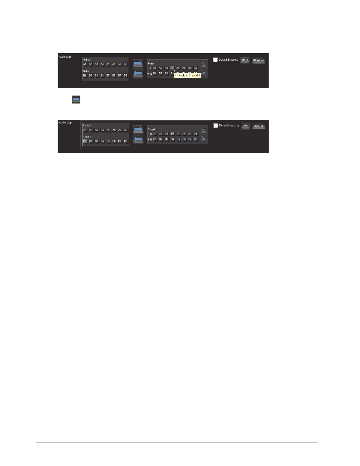
5. On the rightmost map, select the output channel(s).
The following example, the user selected
A4.
6. Click to assign the channel.
The label of the Target button selected in step 5 updates to display the assigned channel (
7. Repeat steps 4 to 6 to map all the channels to target channels.
8. Click
Save.
B1).
54 • Setting up the Network Streams NEWT-IPX User Guide (v4.0)
Page 55
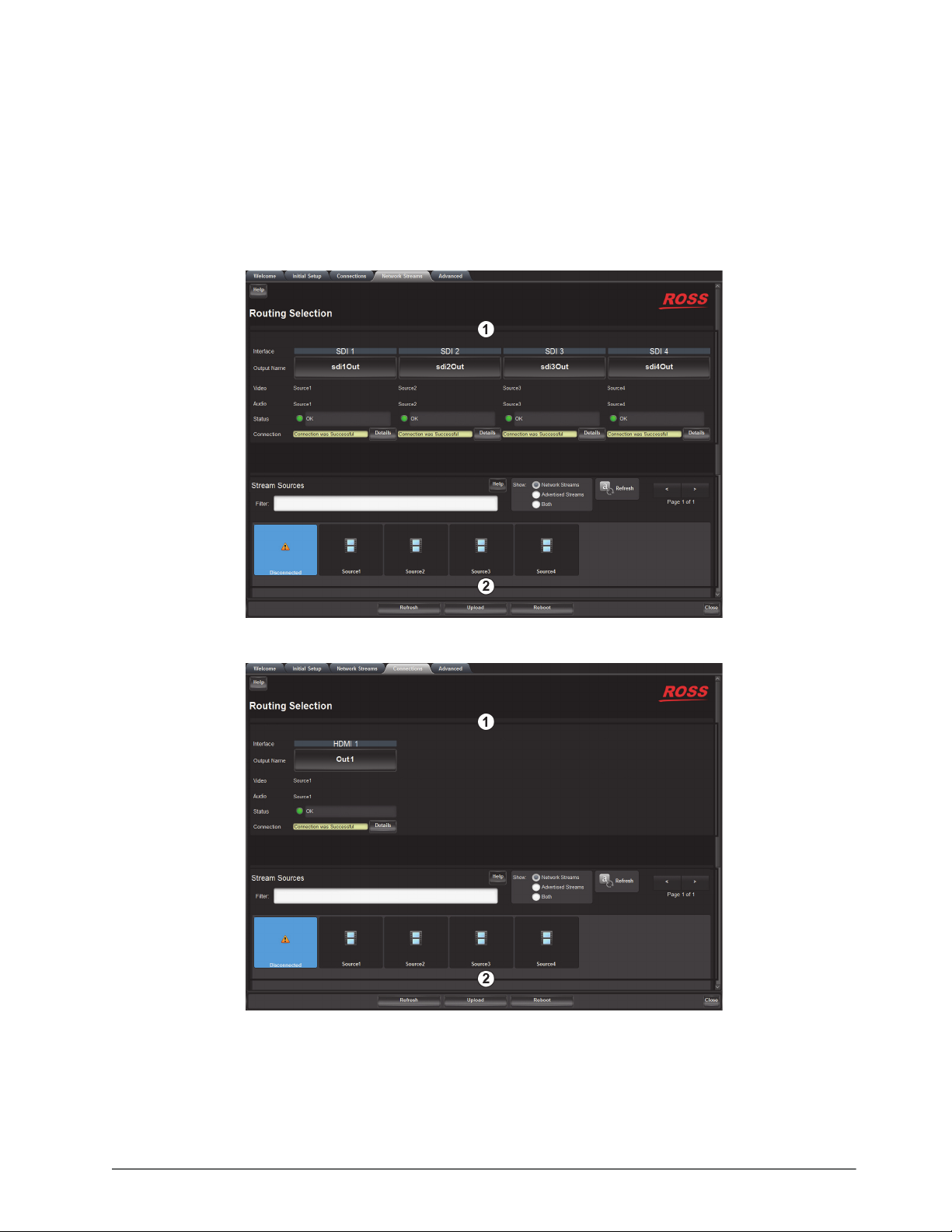
Operation
You can route the NEWT-IPX destinations and stream groups using the options in the Connections tab.
Connections Tab Overview
The Connections tab is organized into two areas: Destinations and Stream Groups.
Figure 14.1 Example of a Populated Connections Tab — IP to 4x3G-SDI Gateway Mode
Figure 14.2 Example of a Populated Connections Tab — UHD-over-IP to HDMI 2.0 Gateway Mode
NEWT-IPX User Guide (v4.0) Operation • 55
Page 56
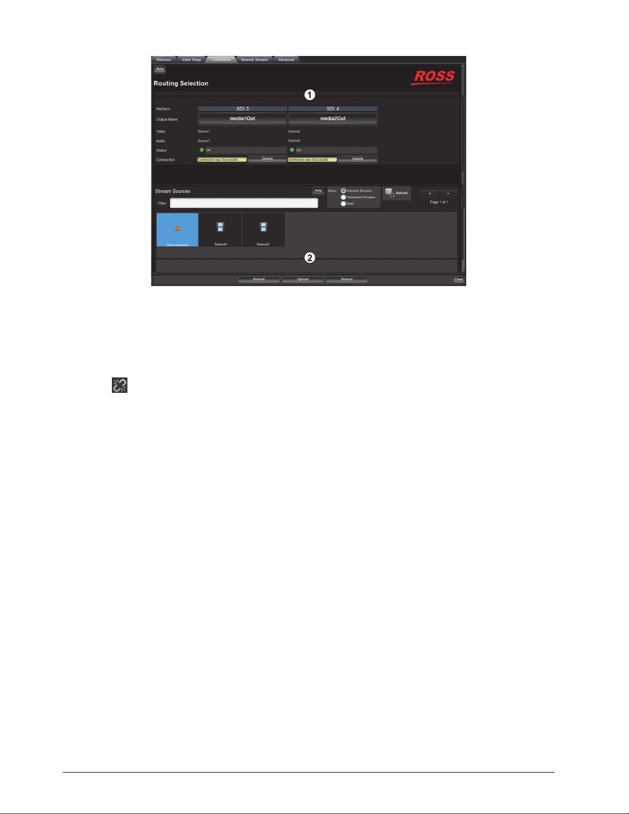
Figure 14.3 Example of a Populated Connections Tab — 2-in/2-out SD/IP Converter Mode
1. Destinations Area
This area displays the available outputs in a series of rows. Each output is represented as a button which is
clicked to include it in the routing switch. Video and Audio read-only fields report the Network Streams assigned
to the output.
The symbol within a stream status field indicates a breakaway condition (the video and audio are not
assigned to the same network stream).
A Status read-only field reports overall communication status and whether any error conditions are occurring on
the SDI or HDMI output.
2. Stream Sources Area
This area displays the available inputs as selectable buttons. Use the Filter field, the
Sources buttons, to narrow down the options displayed in the area.
Show options, or the Stream
Routing the Signals
To route the video and audio signals you must first select an SDI or HDMI output (depending on the Operational
Mode), then a network stream. Keep in mind that routing occurs automatically after a Stream button is selected.
The number of SDI outputs available depends on the Operational Mode. Refer to the section “Specifying an
Operational Mode” on page 35 for details.
To select an output
1. Display the NEWT-IPX interfaces in DashBoard as outlined in the procedure “To access the NEWT-IPX
interfaces in DashBoard” on page 30.
2. Select the Connections tab.
3. In the Output Name row of the Destinations area, locate the button for the output you wish to route.
56 • Operation NEWT-IPX User Guide (v4.0)
Page 57
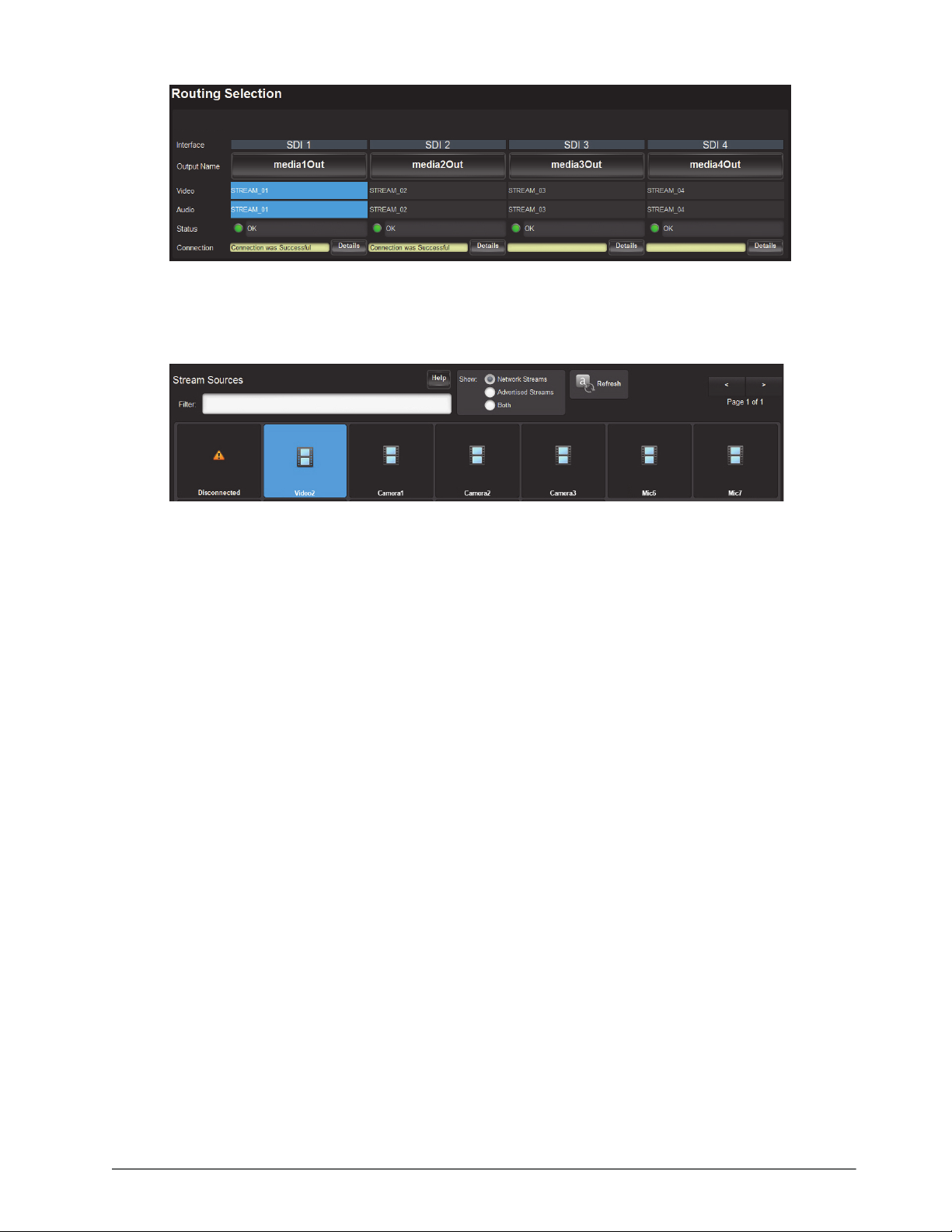
4. Click the required Output button.
To perform the switch
1. In the Stream Groups area, locate the button for the input (Network Stream) you wish to route.
The associated Video and Audio fields report the video and audio signals of the selected Network Stream.
2. Click the required
Network Stream button to perform the switch.
Performing a Breakaway
A breakaway selects a specific receiver group to be switched. This allows a Receiver to route video from one
network stream, and audio from another network stream.
To set up a breakaway
1. Display the NEWT-IPX interfaces in DashBoard as outlined in the procedure “To access the NEWT-IPX
interfaces in DashBoard” on page 30.
2. Select the Connections tab.
3. Select the video to switch as follows:
a. In the Destinations area, select the video field of the interface you wish to include.
b. In the Stream Groups area, select the stream group you wish to route for video for this switch.
4. Select the audio to switch as follows:
a. In the Destinations area, select the audio field of the interface you wish to include.
b. In the Stream Groups area, select the stream group you wish to route for audio for this switch.
If video is selected for a particular interface in the Destinations area and the selected Stream Group has a video
stream, a video receiver is created on the destination. If audio is selected for a particular interface in the
Destinations area and the selected Stream Group has an audio stream, an audio receiver is created on the
destination.
NEWT-IPX User Guide (v4.0) Operation • 57
Page 58

58 • Operation NEWT-IPX User Guide (v4.0)
Page 59
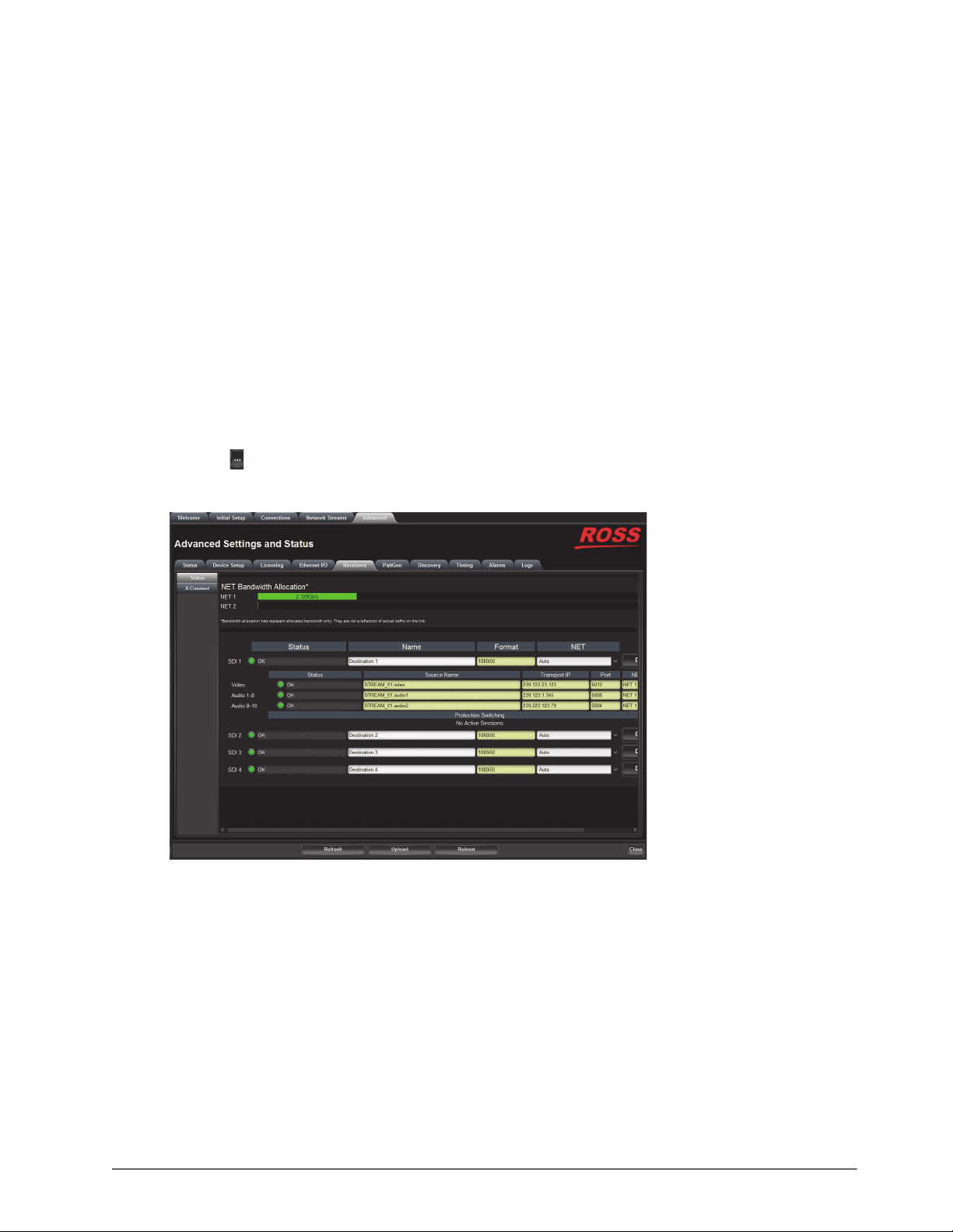
Monitoring
The status of the NEWT-IPX may be monitored via the fields in the DashBoard client software.
All alarms are enabled by default.
Monitoring the Streams
The Receivers tab reports read-only status information for each SDI signal. You can disable or enable the
monitoring of specific SDI streams using the options in the Alarm Enable tab.
To monitor a specific receiver stream
1. Display the NEWT-IPX interfaces in DashBoard as outlined in the procedure “To access the NEWT-IPX
interfaces in DashBoard” on page 30.
2. Select Advanced > Receivers.
3. Locate the row for the SDI signal you wish to monitor.
4. Click the
In the example below, SDI 1 was selected.
button in the required row to display the video and audio status fields for an SDI signal.
Notes on Monitoring the Receiver Streams
This section briefly summarizes the NEWT-IPX behavior when monitoring a receiver stream.
Receiver is configured to receive a stream, but the stream is absent
When a stream is absent (i.e. never detected, or was lost for an extended period of time), the NEWT-IPX does not
output any SDI frames and the SDI link will be inactive.
If a stream was present, but is no longer, the receiver will be in a state of “frame replay” where the NEWT-IPX
continuously outputs the last frame received. This will continue until either the stream resumes (in which case, the
valid video will start playing again), or the receiver is disconnected. If the stream is disconnected, the NEWT-IPX
will stop outputting data.
NEWT-IPX User Guide (v4.0) Monitoring • 59
Page 60

Receiver is not properly configured
The NEWT-IPX will not output data before a receiver is configured (e.g. start-up condition).
Tab is locked and displays an overlay message
The NEWT-IPX lost connection to the PTP Clock and is attempting to re-connect. Once the NEWT-IPX can lock to
the PTP Clock, the tab is unlocked. The following tabs are not locked during a loss of PTP clock connection:
•Status
• Ethernet I/O
• Timing
•Setup
60 • Monitoring NEWT-IPX User Guide (v4.0)
Page 61

Upgrading the Software
The NEWT-IPX software can be upgraded in the field using the CONTROL port and the options available in
DashBoard.
Refer to the NEWT-IPX Software Upgrade Guide if you are upgrading your NEWT-IPX from a version prior to
v.2.20.0.
To upgrade the software on the NEWT-IPX
1. Visit the Ross View website (http://www.rossvideo.com/newt) for the latest software version file.
2. Display the NEWT-IPX interfaces in DashBoard as outlined in the procedure “To access the NEWT-IPX
interfaces in DashBoard” on page 30.
3. Select
4. Navigate to the file you want to upload.
5. Click
6. Monitor the upgrade.
Upload, located near the bottom of the DashBoard interface, to display the Select file Upload dialog.
Open > Finish.
Clicking Cancel or No returns you to the Uploading to Selected Devices dialog without rebooting the device(s).
• Each NEWT-IPX device is temporarily taken off-line during the reboot process.
• The process is complete once the status indicators for the Card state and Connection fields in the Status
tab return to their previous status.
If the NEWT-IPX fails to upgrade correctly, contact Ross Technical Support for an upgrade file and instructions
on using the Micro SD Card slot.
NEWT-IPX User Guide (v4.0) Upgrading the Software • 61
Page 62

62 • Upgrading the Software NEWT-IPX User Guide (v4.0)
Page 63
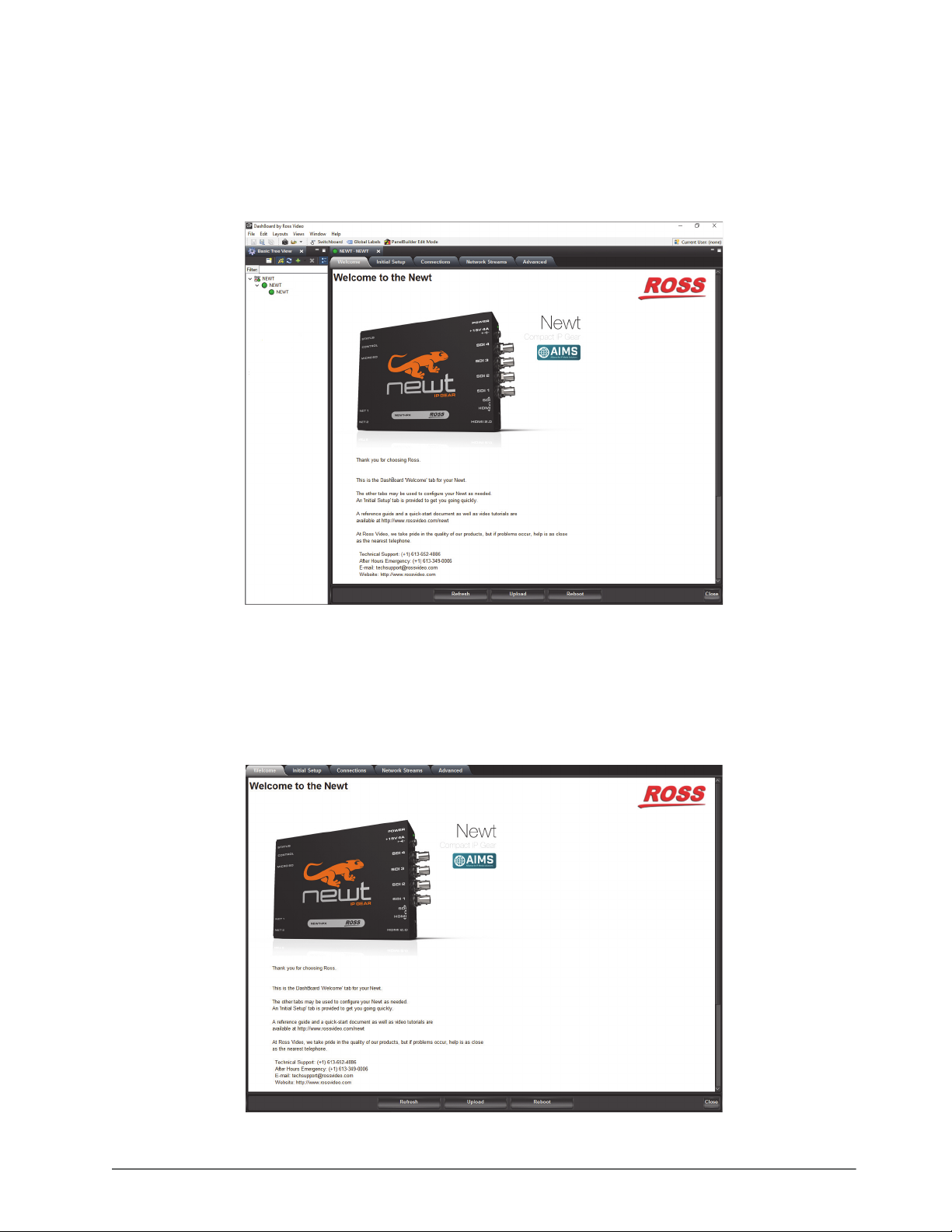
DashBoard Interface Overview
The DashBoard client software enables you to monitor, configure, and operate your NEWT-IPX. The NEWT-IPX
groups the configuration, monitoring, and operating features as a series of tabs in the DashBoard client window.
Each tab provides access to specific configuration options for your NEWT-IPX.
Figure 17.1 Example of the NEWT-IPX Tabs in a DashBoard Window
Welcome Tab
The Welcome tab displays on initial start-up of the NEWT-IPX in DashBoard. Once the initial settings are
configured and applied to the NEWT-IPX, you can hide the Welcome and Initial Setup tabs by selecting Initial
Setup > Hide Welcome tab and/or Initial Setup > Hide Initial Setup Wizard tab (and then clicking
Refresh).
Figure 17.2 Example of the Welcome Tab
NEWT-IPX User Guide (v4.0) DashBoard Interface Overview • 63
Page 64
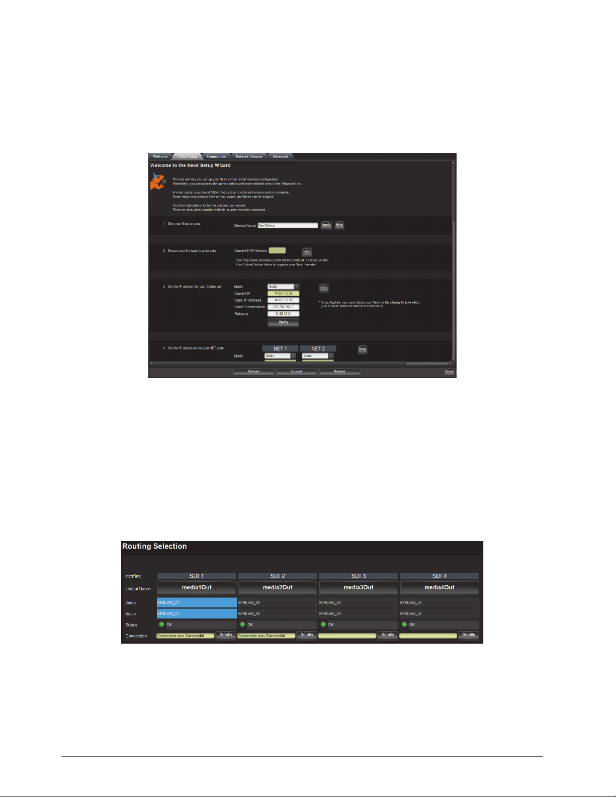
Initial Setup Tab
The Initial Setup tab provides access to the Newt Setup Wizard. This tab helps you to quickly set up your
NEWT-IPX and proceed to configuring your Network Streams and Connections. Help buttons are provided
throughout the tab to provide additional information on the menus and settings.
The same controls are available in the Advanced tabs. Refer to the section “Advanced Tabs” on page 68 for
details.
Figure 17.3 Example of the Initial Setup Tab
Connections Tab
The Connections tab is a patch-panel style interface that enables the NEWT-IPX to connect to available senders on
the network.
Destinations Area
The Destinations area is located at the top of the Connections tab and provides options for routing video and audio
signals to the outputs on the NEWT-IPX. From this area you can quickly select outputs and monitor the status of the
output signals.
Figure 17.4 Connections Tab — Example of a Destinations Area
Table 17.1 summarizes the buttons, menus, and fields available in the Destinations area of the Connections tab.
64 • DashBoard Interface Overview NEWT-IPX User Guide (v4.0)
Page 65

Table 17.1 Connections Tab — Destinations Area
Item Parameters Description
Interface # Indicates the physical connection on the
NEWT-IPX
Output Name # Each button represents an output that is configured
and available for switching
Video (read-only) # Indicates the network stream currently used by the
specified output.
Select a Video button to specify a video-only
breakaway.
Audio (read-only) # Indicates the network stream currently used by the
specified output.
Select an Audio button to specify an audio-only
receiver for a breakaway
Status (read-only) OK (Green) No errors are detected on this output
Off (Green) This SDI output is disabled
Alarm Suppressed (Green) An alarm condition is present, but the alarm is
disabled on the Alarm Enable tab
Network Delay Too Big
(Yellow)
No Packets Received
(Yellow)
The link offset selected by the user is smaller than
the propagation delay of the network
The configured destination IP stream(s) is not
receiving any packets; stream might not be on the
network or experiencing other issues
System Clock Is In Failure
(Red)
The NEWT-IPX is unable to re-obtain a stable
clock source. Sessions cannot be created until this
condition is fixed.
It is recommended to navigate to the Advanced >
Timing > PTP tab to check the status of the PTP
and update the Configuration settings.
Once PTP is locked again, the Network Groups
will need to be disconnected and then re-connected
to clear the alarm.
Param Out Of Range (Red) One of the following is occurring:
• A Destination was configured with an invalid
setting
• Two receivers with the same network stream
were created. NEWT-IPX can only subscribe to a
stream once.
Connection (read-only) Connection was Successful Indicates the connection status between the
Not in Use
selected input and output
<blank>
Details Opens the Details dialog that provides more
information about the state of the connection
NEWT-IPX User Guide (v4.0) DashBoard Interface Overview • 65
Page 66
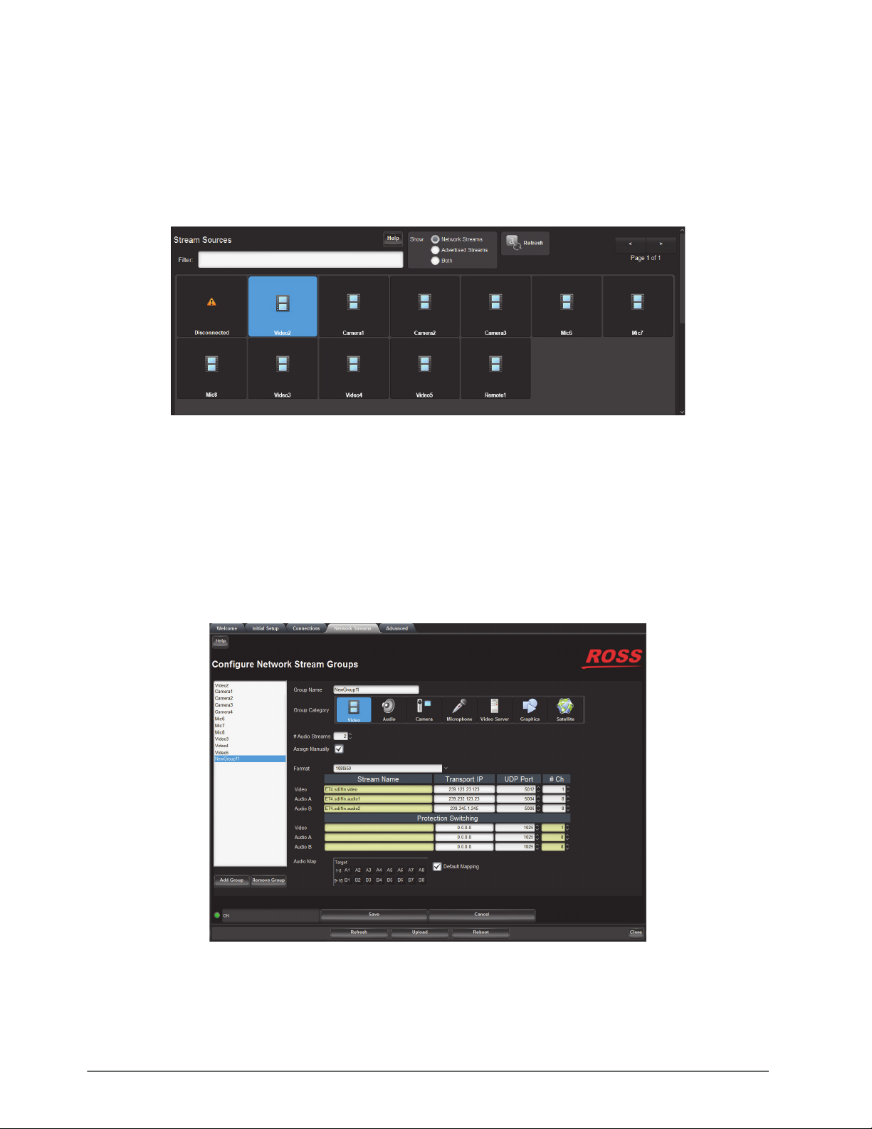
Stream Sources Area
The Stream Sources area is located on the bottom half of the Connections tab. From this area you can route any
source signal to an output, monitor its status, and filter the stream available based on type.
Each button displayed here represents a configured network stream. You can filter what network streams are
displayed using the Filter field (filtering according to the text entered in the filed), by selecting one of the Stream
Sources buttons (displays only the network streams assigned to that Category), and/or using the Show options
(Network Streams, Advertised Streams, Both).
Figure 17.5 Connections Tab — Example of a Stream Source Area
Once a Destination is selected, clicking a Stream Source button performs an immediate switch (a hot-punch).
Network Streams Tab
The options in the Network Streams tab enable you to create and manage the IP streams in your system. Advertised
streams are those that the NEWT-IPX automatically detects as defined by the RAVENNA protocol. You can also
define a stream by manually populating the Transport IP, Port, and DSCP fields for the video and audio signals.
Once a Network Stream is defined, it is made available for use in the Connections tab.
Figure 17.6 Network Streams Tab
Table 17.2 outlines the options displayed in the Network Streams tab starting from the left-most area of the tab.
If the ST 2022-7/Seamless Protection Switching box is selected in the Setup tab, an extra Video row and an
extra Audio row displays for Protection Switching setup for a stream.
66 • DashBoard Interface Overview NEWT-IPX User Guide (v4.0)
Page 67

Table 17.2 Network Streams Tab
Item Parameters Description
Configure Network Stream Groups
List <name> Lists the configured groups for the NEWT-IPX
Add Group Enables you to configure a new stream group
Remove Group Deletes the selected group
Group Name <text> Specifies a unique identifier for the group
Group Category Assigns the stream to a type of essence.
This is useful when filtering the streams on the
Connections tab.
# Audio Streams # Specifies the number of audio streams available in
the stream group. The default value is 2.
Assign Manually Selected Enables you to manually enter the Transport IP,
Port, and DSCP fields for a specific session. This
is useful when accessing non-RAVENNA streams.
Cleared The Transport IP, Port, and DSCP fields are
determined by the assigned Advertised Stream
Advertised Network Streams
Video None Lists the discovered RAVENNA sessions. Select a
#
session to auto-fill the Video and/or Audio fields.
Audio # None
#
Format # Specifies the video format of the signal available
for the stream
Manually Specified Streams
Stream Name <name> Assigns a unique identifier for the stream
Transport IP #.#.#.# Specifies the network socket for the video/audio
data for the session. This value is auto-populated
when you select an Advertised Stream.
UDP Port # Specifies the source port to connect to the
advertised stream. This must match the source you
are attempting to connect to.
# Ch # Specifies the maximum number of audio channels
in the specified stream
Protection Switching
Stream Name <name> Assigns a unique identifier for the stream
Transport IP #.#.#.# Specifies the network socket for the video/audio
data for the session. This value is auto-populated
when you select an Advertised Stream.
UDP Port # Specifies the source port to connect to the
advertised stream. This must match the source you
are attempting to connect to.
NEWT-IPX User Guide (v4.0) DashBoard Interface Overview • 67
Page 68
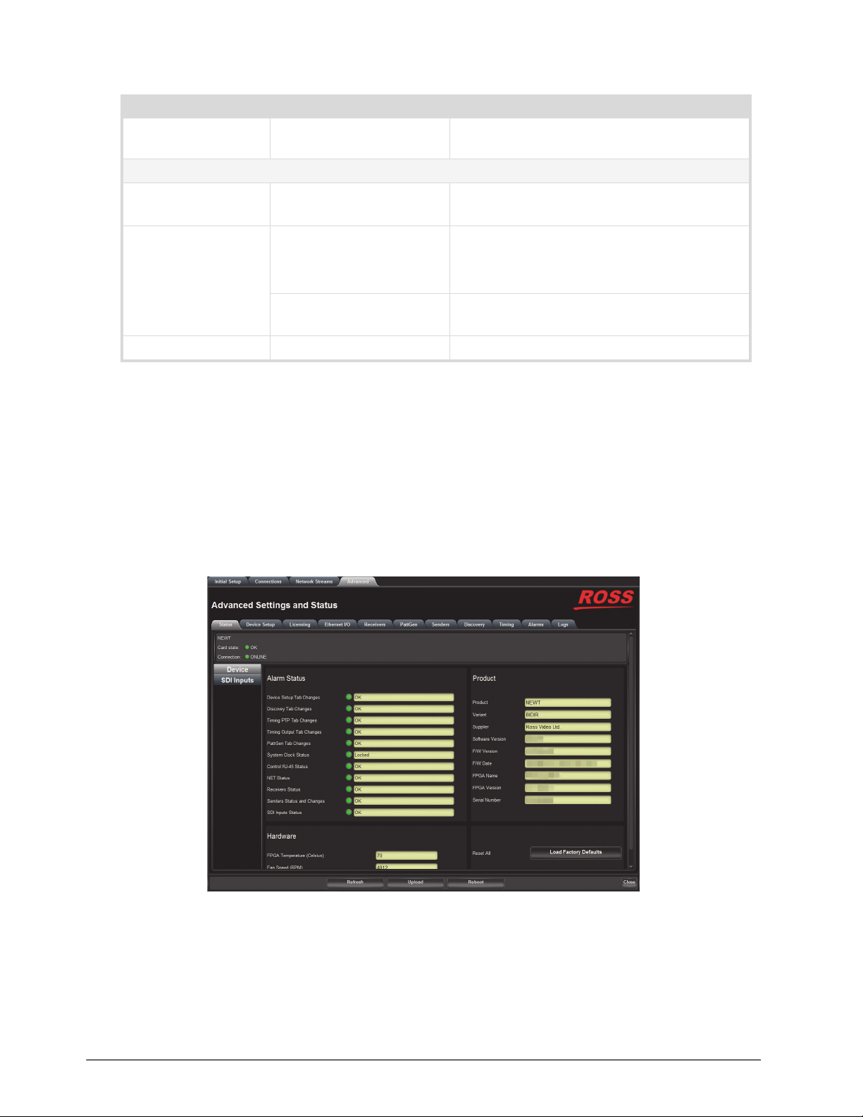
Table 17.2 Network Streams Tab
Item Parameters Description
# Ch # Specifies the maximum number of audio channels
in the specified stream
Audio Map
Target Use the audio map to assign audio channels, and
determine their hierarchy, to an audio stream
Default Mapping Selected Applies a default audio mapping of 1:1 where:
• Target 1-8 is mapped to A1-A8
• Target 9-16 is mapped to B1-B8 etc.
Cleared The default audio map is not applied; user can
assign audio channels as required
Edit Click to display the audio map editing options
Advanced Tabs
The Advanced sub-tabs expand the controls available in the Initial Setup tab.
Status Tab
The Status tab provides read-only hardware information, signal status, and general product information for your
NEWT-IPX. The tab is organized into four distinct areas in the DashBoard window: Signal, Product, Hardware, and
Load Factory Defaults.
If the Operational Mode is set to 2-in/2-out SDI/IP Converter, there are two sub-tabs: Device, and SDI Inputs.
Figure 17.7 Example of the Status Tab — Operational Mode set to 2-in/2-out SDI/IP Converter
68 • DashBoard Interface Overview NEWT-IPX User Guide (v4.0)
Page 69

Alarm Status Area
Table 17.3 summarizes the read-only information displayed in the Device > Alarm Status area.
Table 17.3 Status Tab — Alarm Status
Item Parameters Description
Device Setup Tab Changes Reports if there are unsaved changes made to the Advanced > Device Setup tab
Discovery Tab Changes Reports if there are unsaved changes made to the Advanced > Discovery tab
Timing PTP Tab Changes Reports if there are unsaved changes made to the Advanced > Timing > PTP tab
Timing Output Tab Changes Reports if there are unsaved changes made to the Advanced > Timing > Outputs tab
PattGen Tab Changes Reports there are unsaved changes made to the Advanced > PattGen tab
System Clock Status Reports the status of the PTP Clock connection
Control RJ-45 Status Reports the same information as the Advanced > Ethernet I/O > Control RJ-45 >
Link Status field. Refer to Table 17.10 for more information.
NET Status Reports the same information as the Advanced > Ethernet I/O > NET # > Link
Status fields. Refer to Table 17.10 for more information.
Receivers Status Reports the same information as the individual alarms in the Receivers tab. Refer to
the section “Receivers Tabs” on page 75.
Senders Status and Changes Reports if there are unsaved changes made to the Advanced > Senders tab
SDI Inputs Status Reports the same information as the Advanced > Status > SDI Inputs status fields.
Refer to Table 17.7 for more information
Product Area
Table 17.4 summarizes the read-only information displayed in the Device > Product area.
Table 17.4 Status Tab — Product
Item Parameters Description
Product Indicates the product name of the module
Variant Indicates the option(s) enabled on the module
Supplier Indicates the supplier/manufacturer of the device
Software Version # Indicates the software version running on the
module
F/W Version # Indicates the firmware version running on the
module
F/W Date # Indicates the date the current firmware was loaded
on to the module
FPGA Name # Indicates the FPGA load running on the module
FPGA Version # Indicates the FPGA version running on the module
Serial Number # Indicates the factory installed serial number of the
module
NEWT-IPX User Guide (v4.0) DashBoard Interface Overview • 69
Page 70
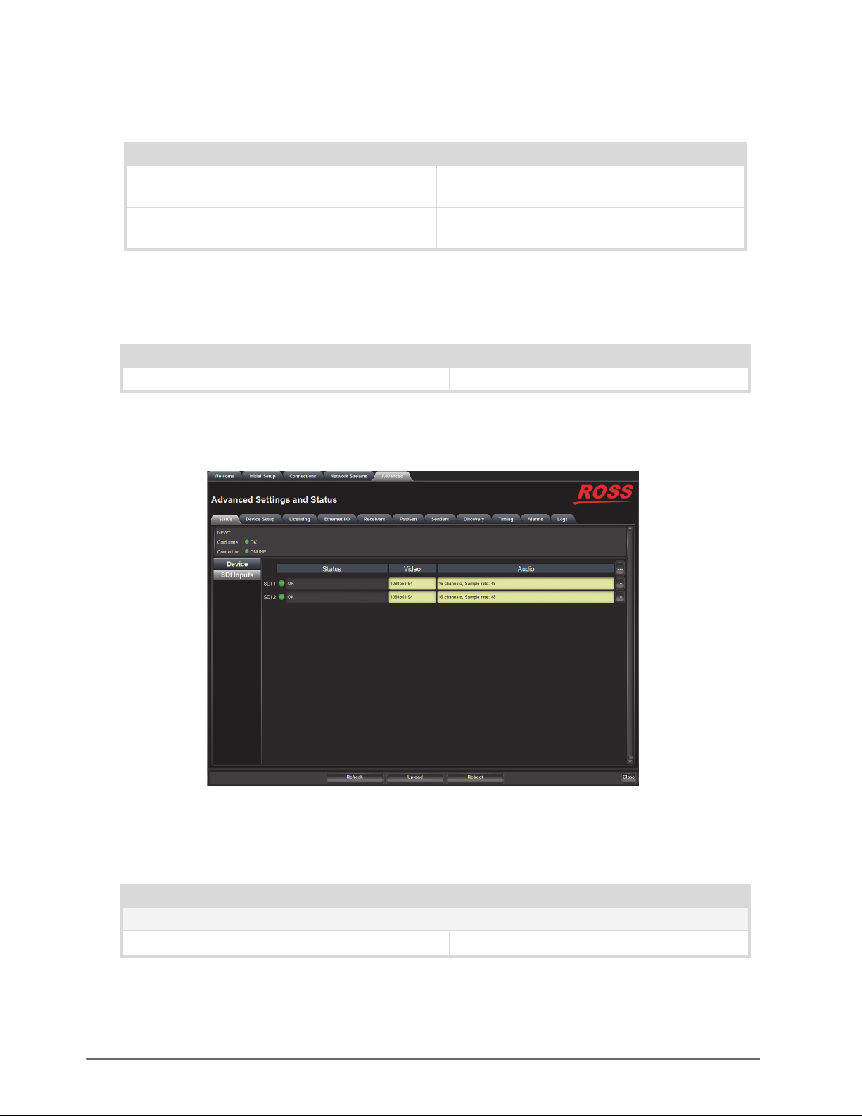
Hardware Area
Table 17.5 summarizes the read-only information displayed in the Device > Hardware area.
Table 17.5 Status Tab — Hardware
Item Parameters Description
FPGA Temperature
# Indicates the FPGA Core temperature.
(Celsius)
Fan Speed (RPM) # Reports the speed of the fan installed inside the
NEWT-IPX chassis
Load Factory Defaults Area
Table 17.6 summarizes the read-only information displayed in the Device > Load Factory Defaults area.
Table 17.6 Status Tab — Device Settings
Item Parameters Description
Reset All Load Factory Defaults Sets certain editable settings to the default values
SDI Inputs Tab
The SDI Inputs tab only displays when the Operational Mode is set to 2-in/2-out SDI/IP Converter.
Figure 17.8 Example of the Status > SDI Inputs Tab
Table 17.7 summarizes the read-only information displayed in the SDI Inputs tab.
Table 17.7 Status Tab — SDI Inputs Tab
Item Parameters Description
SDI #
Status OK (Green) Indicates the SDI input signal is detected and valid
70 • DashBoard Interface Overview NEWT-IPX User Guide (v4.0)
Page 71
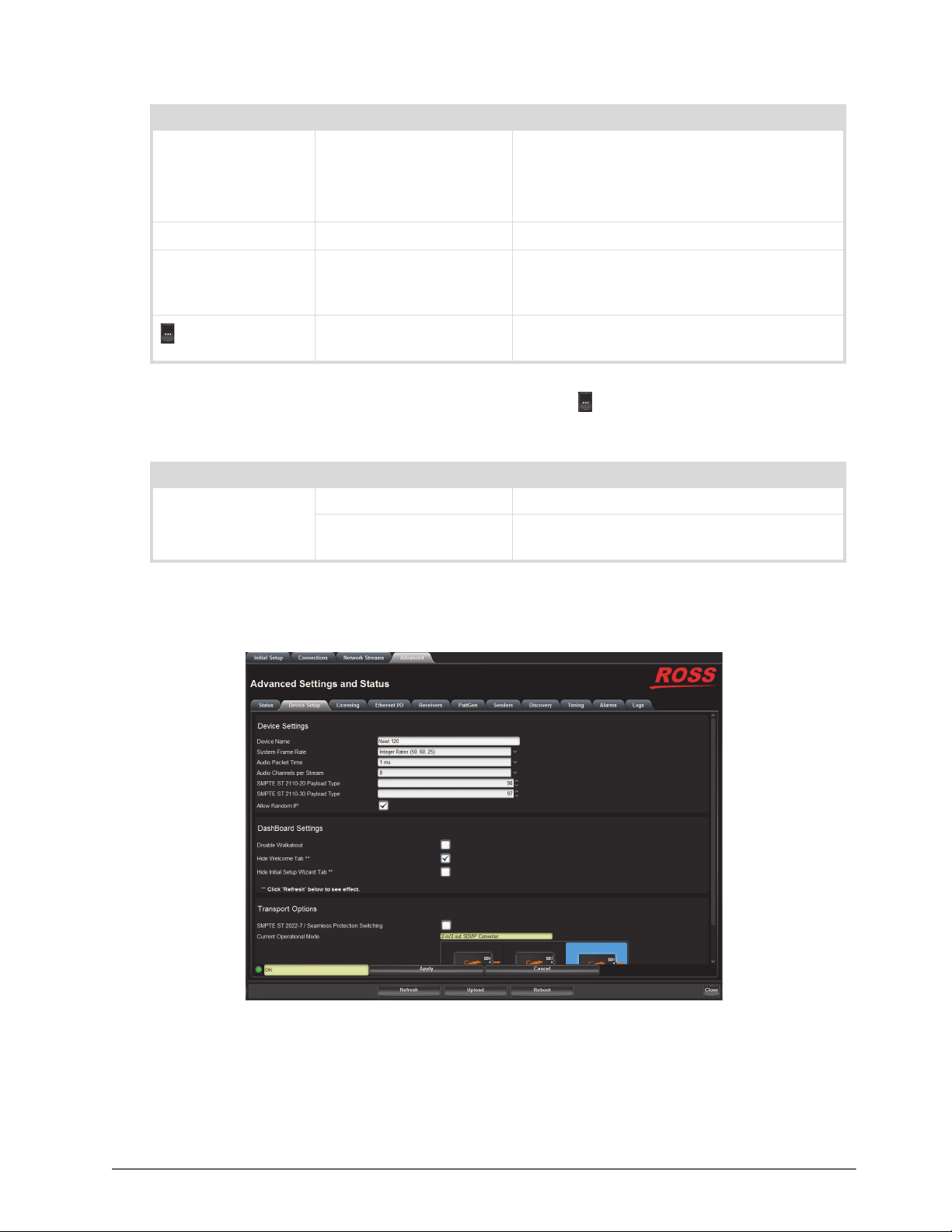
Table 17.7 Status Tab — SDI Inputs Tab
Item Parameters Description
Status No Input (Red) Indicates one of the following is occurring:
• the SDI input signal is not detected
• the system frame rate does not match the input
frame rate
Video # Indicates the video input signal format
Audio # channels, Sample rate: # Indicates the number of audio groups that are
present in the specified input signal, and the
sample rate of the AES signal
Displays additional audio status information for
the specified SDI input signal
Table 17.8 summarizes the read-only information displayed when the button is selected for an SDI row.
Table 17.8 SDI Inputs Tab — SDI Inputs, Additional Information
Item Parameters Description
Audio CH # Present Indicates the specified audio channel is detected
No Signal Indicates the specified audio channel is not
available
Device Setup Tab
The Device Setup tab provides settings such as Device Name, DashBoard settings, and operational modes.
Figure 17.9 Device Setup Tab
NEWT-IPX User Guide (v4.0) DashBoard Interface Overview • 71
Page 72

Table 17.9 summarizes the options displayed in the Device Setup tab.
Table 17.9 Device Setup Tab
Item Parameters Description
Device Settings
Device Name <text> Specifies a unique identifier for this NEWT-IPX.
This name is used to identify the streams the
NEWT-IPX is managing.
System Frame Rate Integer Rates (50, 60, 25) Inputs, senders, and receivers must use a video
Non-Integer Rates (59.94,
29.97)
format that matches this rate. This setting is
updated and applied once PTP is locked.
Audio Packet Time 1ms Adds an offset to the audio streams if you suspect
125us
the audio packets may be received out of order or
delayed.
This impacts all connected audio streams.
Applying a new Audio Packet Time automatically
disconnects all audio streams.
It is recommended to set the Audio Packet Time
before configuring your audio streams.
Audio Channels per
Stream
SMPTE ST 2110-20
Payload Type
# Specifies the maximum number of audio channel
available for configuration. The default is 8.
# Specifies the 7-bit numeric value that identifies the
SMPTE 2110-20 RTP payload format the
NEWT-IPX supports. The default is 98.
SMPTE ST 2110-30
Payload Type
# Specifies the 7-bit numeric value that identifies the
SMPTE 2110-30 RTP payload format the
NEWT-IPX supports. The default is 97.
Allow Random IP Selected Enables the NEWT-IPX to choose a random IP
Address for any stream when its IP Address field is
set to 0.0.0.0
Cleared Disables this feature. An IP Address must be
specified for all streams.
DashBoard Settings
Disable Walkabout Selected Enables the Walkabout feature of DashBoard to
detect the NEWT-IPX on the network
Cleared Disables this feature.
Hide Welcome Tab Selected The Welcome tab does not display in the
DashBoard window
Cleared The Welcome tab displays in the DashBoard
window
Hide Initial Setup
Wizard Tab
Selected The Initial Setup tab does not display in the
DashBoard window
Cleared The Initial Setup tab displays in the DashBoard
window
Transport Options
72 • DashBoard Interface Overview NEWT-IPX User Guide (v4.0)
Page 73
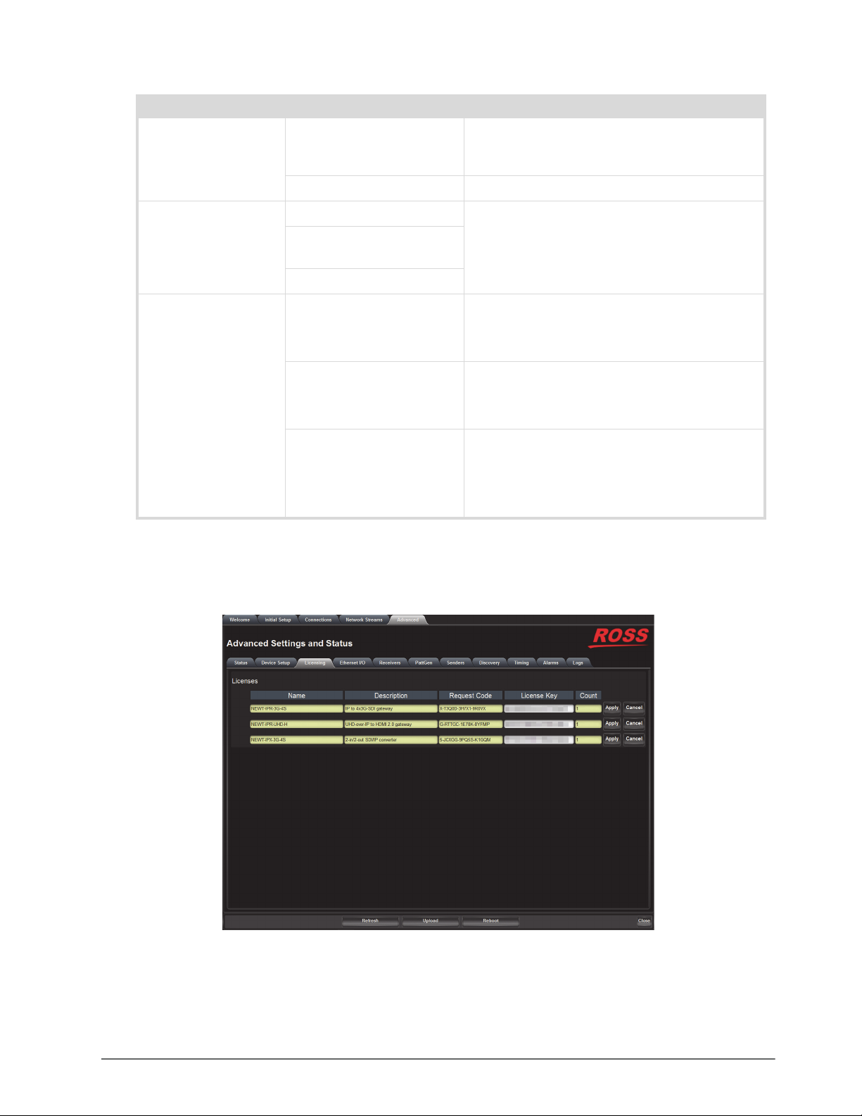
Item Parameters Description
SMPTE ST 2022-7
/Seamless Protection
Switching
Table 17.9 Device Setup Tab
Selected Enables you to protect your streams by allowing
the NET ports to carry a protection stream when
operating in a redundant network
Cleared Disables this feature
Current Operational
Mode (read-only)
Operational Mode on
Reboot
IP to 4x3G-SDI Gateway Reports what Operational Mode the NEWT-IPX is
UHD-over-IP to HDMI 2.0
Gateway
2-in/2-out SDI/IP Converter
IP to 4x3G-SDI Gateway The NEWT-IPX is configured to operate with:
UHD-over-IP to HDMI 2.0
Gateway
2-in/2-out SDI/IP Converter The NEWT-IPX is configured to operate with:
set to. Use this field to identify the number and
type of outputs that are enabled on the module.
• Two NET inputs
• Four SDI outputs
The NEWT-IPX is configured to operate with:
• Two NET inputs
• One HDMI 2.0 output
• Two bi-directional NET ports
• Two SDI inputs
• Two SDI outputs
Licensing Tab
Ross Video uses license keys to control user access to specific NEWT-IPX features. You manage your license keys
via the options in the Advanced > Licensing tab. Refer to the chapter “Licensed Features” on page 33 for details.
Figure 17.10 Licensing Tab
NEWT-IPX User Guide (v4.0) DashBoard Interface Overview • 73
Page 74
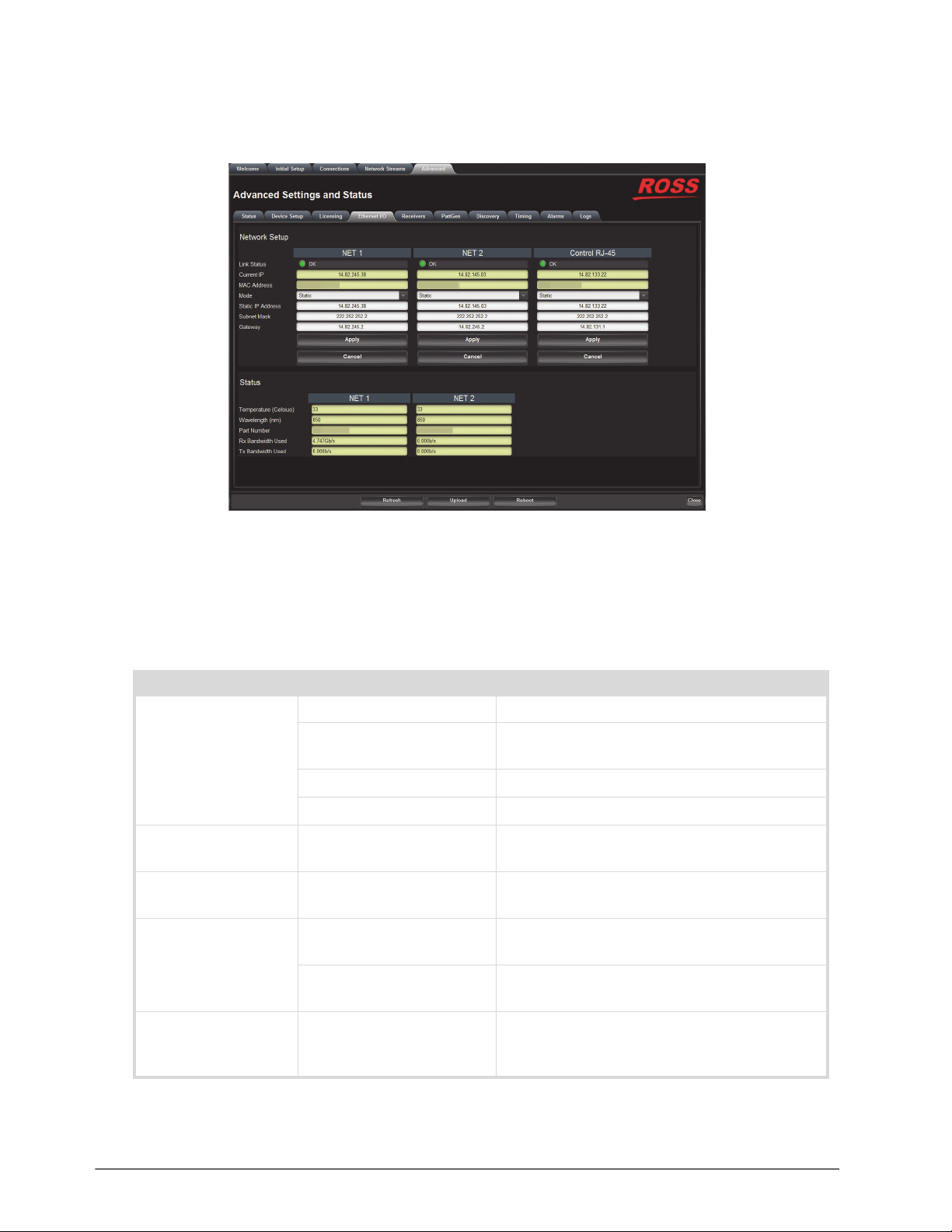
Ethernet I/O Tab
Use the Ethernet I/O tab to configure the network settings for the CONTROL, NET 1, and NET 2 ports on the
NEWT-IPX.
Figure 17.11 Ethernet I/O Tab
Network Setup Area
Table 17.10 summarizes the fields and menus displayed for configuring the network settings of the CONTROL and
NET ports. Note that each port is configured independently.
Table 17.10 Ethernet I/O — Network Setup
Item Parameters Description
Link Status (read-only) OK (Green) The link for the specified port is valid
Alarm suppressed (Green) The Link Down or Not Present boxes in the Alarm
Enable tab is cleared (not selected) for this port
Not Present (Yellow) No SFP Module is detected in the NET port
Link Down (Red) The link for the specified port is invalid (fails)
Current IP (read-only) # Indicates the IP Address currently assigned to the
NEWT-IPX for the specified port
MAC Address
(read-only)
Mode Static The user manually supplies the network settings
# Indicates the MAC Address currently assigned to
the NEWT-IPX for the specified port
for the specified port
DHCP Automates the assignment of the network settings
for the specified port
Static IP Address # Specifies the static IP Address for the NEWT-IPX
the user wants to manually assign to the specified
port
74 • DashBoard Interface Overview NEWT-IPX User Guide (v4.0)
Page 75
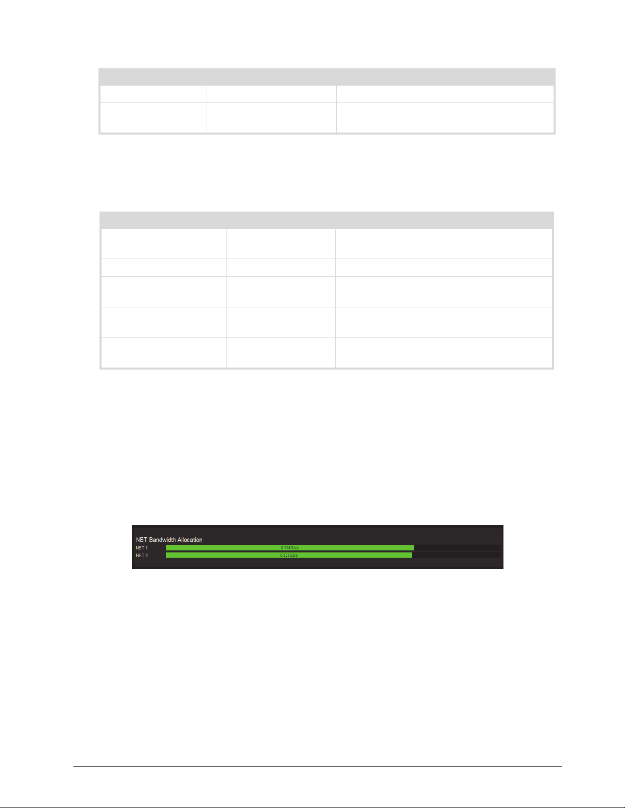
Table 17.10 Ethernet I/O — Network Setup
Item Parameters Description
Subnet Mask # The subnet mask for the specified port
Gateway # The gateway for communications outside of the
local area network (LAN)
Status Area
Tab le 1 7. 11 summarizes the read-only fields displayed for each NET port.
Table 17.11 Ethernet I/O — Status
Item Parameters Description
Temperature (Celsius) # Internal temperature as reported by the specified
NET port
Wavelength (nm) # Indicates the transmitted wavelength
Part Number # Indicates the part number of the module installed
in the specified NET port
Rx Bandwidth Used # Reports the amount of data the NEWT-IPX is
currently receiving on the specified NET port
Tx Bandwidth Used # Reports the amount of data the NEWT-IPX is
currently transmitting on the specified NET port
Receivers Tabs
The Receivers tab is organized into two sub-tabs: Status and X-Connect.
Status Tab
The Status tab provides details on each of the IP receivers (NET ports) of the NEWT-IPX.
The top of the Status tab displays a read-only field for each configured NET port on the NEWT-IPX. These fields
report the bandwidth allocated by the Receiver NET port.
The value displayed within each bar indicates the port utilization by the active receivers.
Figure 17.12 Receivers > Status Tab — Example of the NET Bandwidth Area
If the bandwidth bar is green, the allocated bandwidth is below 100%.
The SDI Receiver area of the tab, located at the bottom, duplicates the information reported in the Ethernet I/O tab.
Each SDI is represented as a row in the tab and provides the items and parameters.
NEWT-IPX User Guide (v4.0) DashBoard Interface Overview • 75
Page 76
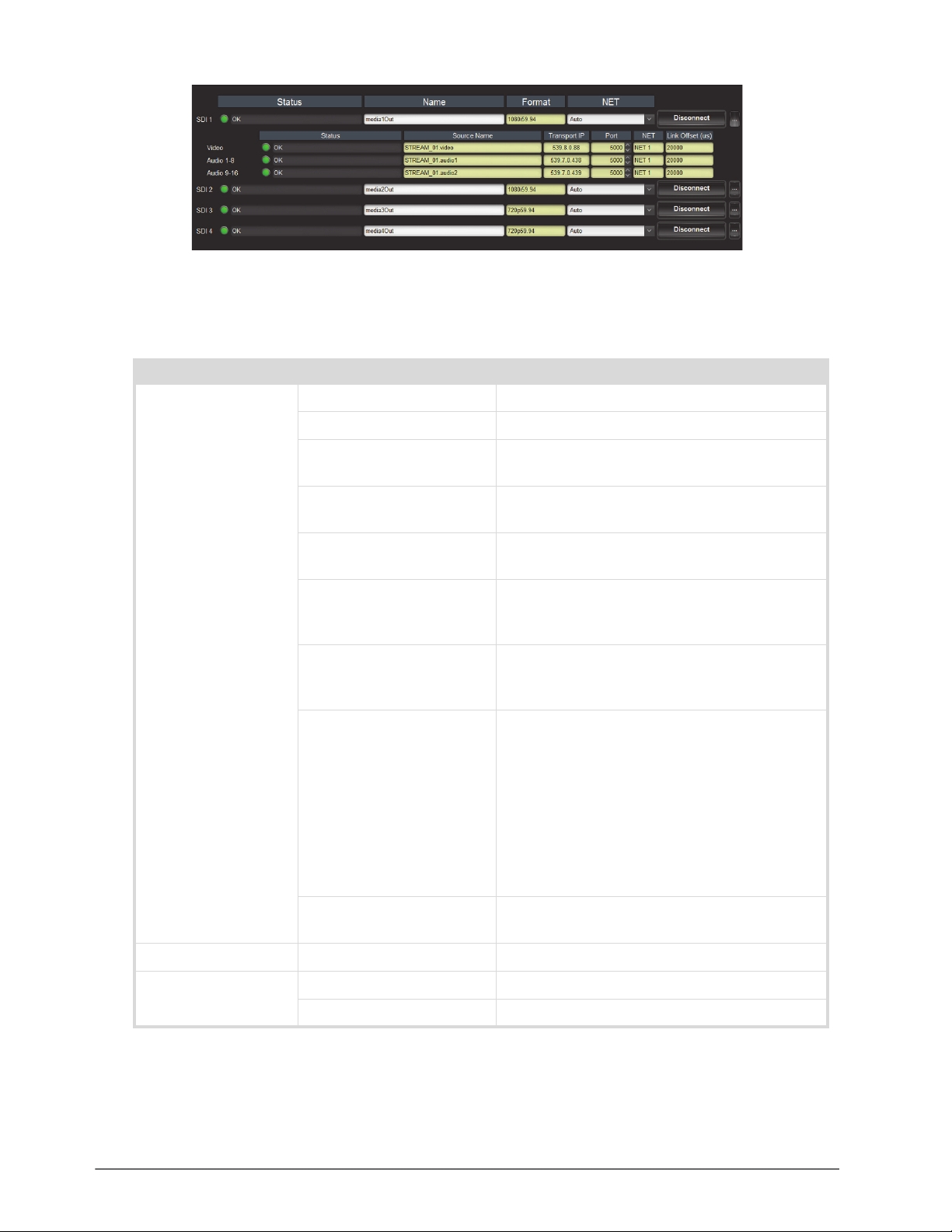
Figure 17.13 Receivers >Status Tab — Example of the SDI Receiver Area with Four SDI Outputs
Table 17.12 outlines the read-only fields and menus available to configure the receiver settings for each SDI.
Table 17.12 Receivers > Status Tab — SDI Receiver Configuration Area
Item Parameters Description
Status (read-only) OK (Green) No errors are detected on this SDI connection
Off (Green) This SDI connection is disabled
Alarm Suppressed (Green) An alarm condition is present, but the alarm is
disabled on the Alarm Enable tab
Apply Changes (Yellow) This receiver has unsaved settings. Click
Apply at
the bottom of the tab to save your settings.
Network Delay Too Big
(Yellow)
No packets received
(Yellow)
The link offset selected by the user is smaller than
the propagation delay of the network
The configured receiver IP stream(s) is not
receiving any packets; stream might not be on the
network or experiencing other issues
Param Out of Range (Red) Two receivers with the same network stream were
created. NEWT-IPX can only subscribe to a stream
once.
System clock is in failure
(Red)
The NEWT-IPX is unable to re-obtain a stable
clock source. Sessions cannot be created until this
condition is fixed.
It is recommended to navigate to the Timing > PTP
tab to check the status of the PTP and update the
Configuration settings.
Once PTP is locked again, the Network Groups
will need to be disconnected and then re-connected
to clear the alarm.
Not In Use (Gray) Indicates the SDI port is not actively in use; verify
the connection on the physical port of the chassis
Name <text> Assigns an unique identifier to the receiver stream
Format (read-only) # Indicates the video format detected on the stream
Unknown Indicates the detected format is unsupported
76 • DashBoard Interface Overview NEWT-IPX User Guide (v4.0)
Page 77
Table 17.12 Receivers > Status Tab — SDI Receiver Configuration Area
Item Parameters Description
NET NET # Specifies the NET port when subscribing to
streams
Auto The NEWT-IPX automatically selects the available
NET port
Disconnect Stops that session and the Receiver outputs black
Table 17.13 summarizes the read-only information that displays when the button is selected at the end of a row.
If the ST 2022-7/Seamless Protection Switching box is selected in the Setup tab, an extra Video row and an
extra Audio row displays for Protection Switching setup.
Table 17.13 Receivers > Status Tab — Additional Status
Item Parameters Description
Video
Status OK (Green) No errors are detected on the video signal
Status Off (Green) This SDI video stream is disabled
Alarm suppressed (Green) An alarm condition is present, but the alarm is
disabled on the Alarm Enable tab
Source Name xx.yy.video The source name is determined by the stream that
is connected
Transport IP # Specifies the IP Address for the video stream
<blank> The NEWT-IPX firmware provides an IP when the
session is created
Port # Indicates the port associated with the IP address
and the communication protocol for the video
essence
NET # Indicates the NET port that the video signal is
derived from
Link Offset (us) # Reports the Video Delay value set in the Timing >
Outputs tab for the SDI output
Audio #
Status OK (Green) No errors are detected on the audio signal
Off (Green) The audio channels are disabled or unavailable
Alarm suppressed (Green) An alarm condition is present, but the alarm is
disabled on the Alarm Enable tab
Source Name xx.yy.audio# The source name is determined by the stream that
is connected
Transport IP #.#.#.# Specifies the IP Address for the audio stream
<blank> The NEWT-IPX firmware provides an IP when the
session is created
Port # Indicates the port associated with the IP address
and the communication protocol for the audio
essence
NEWT-IPX User Guide (v4.0) DashBoard Interface Overview • 77
Page 78
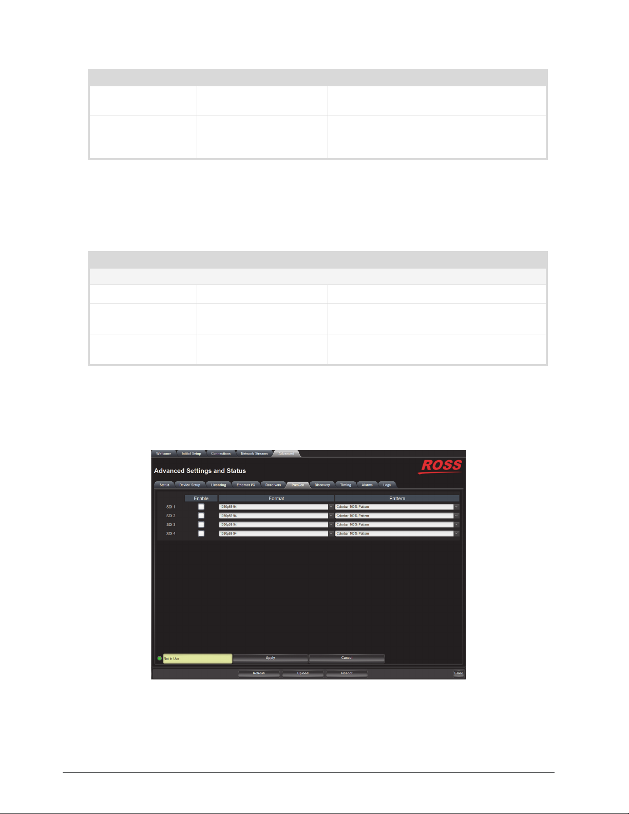
Table 17.13 Receivers > Status Tab — Additional Status
Item Parameters Description
NET (read-only) # Indicates the NET port on the NEWT-IPX that the
audio signal is derived from
Link Offset (us) # Reports the Audio Offset and/or Audio Delay
values set in the Timing > Outputs tab for the SDI
output
X-Connect Tab
The X-Connect tab provides read-only details on the audio mapping of the current audio receiver session(s).
Table 17.14 outlines the Receiver Audio Mapping read-only fields on the X-Connect tab.
Table 17.14 Receivers > X-Connect Tab
Item Parameters Description
Receiver Audio Mapping - SDI # / Destination #
Session # Indicates the specific network session
Stream # Indicates the specific network stream assigned to
the session
Chan # # Indicates the input channel assigned to the
specified SDI # /Destination # output channel
PattGen Tab
The PattGen tab provides options for configuring a pattern generator for an SDI output. The number and type of
outputs depends on the Operational Mode setting. Figure 17.14 is an example of the PattGen tab when the
NEWT-IPX is configured as an IP to 4x3G-SDI Gateway.
Figure 17.14 PattGen Tab
78 • DashBoard Interface Overview NEWT-IPX User Guide (v4.0)
Page 79
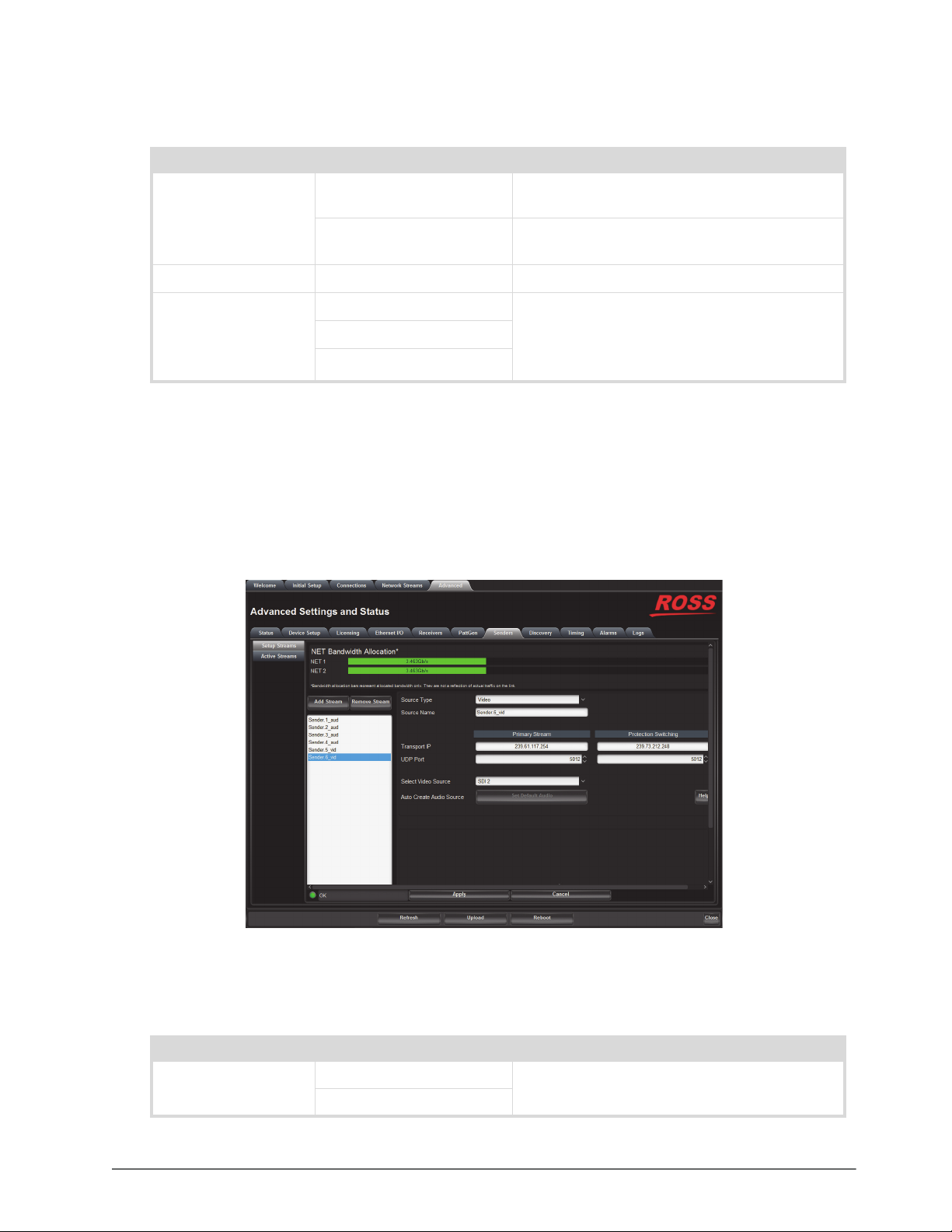
Table 17.15 summarizes the options displayed in the PattGen tab.
Table 17.15 PattGen Tab
Item Parameters Description
Enable Selected The specified output outputs the test pattern
assigned using the Pattern menu
Cleared Disables the pattern generator for the specified
output
Format # Specifies the video format for the pattern generator
Pattern Colorbar 100% Pattern Specifies the type of test pattern to output.
Colorbar 75% Pattern
Pathological Pattern
Note that the test pattern replaces all of the output
picture but not the HANC, while the VANC is
blanked
Senders Tab
The Senders menus are organized into two sub-tabs: Setup Streams and Active Streams. The Senders tab only
displays when the NEWT-IPX is configured as an 2-in/2-out SDI/IP Converter.
Setup Streams Tab
The Setup Streams tab allows you to configure the sender streams for the NEWT-IPX. The Setup Streams tab also
reports the NET bandwidth allocation. If a bandwidth bar is green, the allocated bandwidth is below 75%.
Figure 17.15 Senders — Setup Streams Tab
Table 17.16 summarizes the menus and fields available in the Setup Streams tab.
Table 17.16 Senders — Setup Streams Tap
Item Parameters Description
Source Type Video Specifies the type of data that the new stream will
Audio
NEWT-IPX User Guide (v4.0) DashBoard Interface Overview • 79
transport
Page 80
Table 17.16 Senders — Setup Streams Tap
Item Parameters Description
Source Name <text> Provides a unique identifier for the SDI input
signal. This name is used to identify the data
within your network.
Primary Stream
Transport IP # Specifies the IP Address for the primary stream of
this session
<blank> If the Device Setup > Allow Random IP box is
selected, the NEWT-IPX firmware provides an IP
when the session is created.
UDP Port # Indicates the port associated with the IP address
and the communication protocol for the primary
stream
Protection Switching
Transport IP # Specifies the IP Address for the protection switch
stream
UDP Port # Indicates the port associated with the IP address
and the communication protocol for the protection
switch stream
Select Video Source SDI # Specifies the SDI IN port on the NEWT-IPX
chassis that will supply the data.
Auto Create Audio
Source
Set Default to Audio Automatically maps the audio channels to the
output channels in a 1:1 ratio
This button is disabled when the Source Type is
set to Video.
Active Streams Tab
Table 17.17 lists the fields that display on the Active Streams tab.
Table 17.17 Senders — Active Streams Tab
Item Parameters Description
Video Streams
Name
a
xx.yy Provides a unique identifier for the video data
available on the specified SDI input where:
• xx represents the name of the send as defined in
the Advanced > Senders > Setup Streams tab.
• yy represents the name of the SDI input signal as
defined in the Name field.
80 • DashBoard Interface Overview NEWT-IPX User Guide (v4.0)
Page 81

Table 17.17 Senders — Active Streams Tab
Item Parameters Description
Status (read-only) OK (Green) The sender streams are operating correctly without
errors
Alarm Suppressed (Green) An alarm condition is present, but the alarm is
disabled on the Alarm Enable tab
Apply Changes (Yellow) One or more settings were changed on the Setup
Streams tab. You must click Apply to update the
settings on the NEWT-IPX.
PTP Unstable, try again
(Red)
The NEWT-IPX is unable to obtain a stable clock
source. Sessions cannot be created until this
condition is fixed.
It is recommended to navigate to the Advanced >
Timing > PTP tab to check the status of the PTP
and update the Configuration settings.
Param Out of Range (Red) One of the following is occurring:
• a sender was configured with an invalid setting.
• two senders with the same network source were
created. The NEWT-IPX can only subscribe to a
stream once.
SDI Not Present (Red) A valid SDI signal is not detected on the specified
SDI BNC of the NEWT-IPX
Marked for Removal (Red) The user has disabled the sender but has not
clicked the
Apply button yet
Transport IP #.#.#.# Specifies the IP Address for the video session
UDP Port # Indicates the port associated with the IP address
and the communication protocol for the video
essence
Pause The session is paused (not active)
Remove The sessions is stopped
Audio Streams
Name xx.yy Provides a unique identifier for the audio channels
available on the specified SDI input where:
• xx represents the name of the card as defined in
the Advanced > Senders > Setup Streams tab.
• yy represents the name of the SDI input signal as
defined in the Name field
Status (read-only) Reports the audio activity of the session
Transport IP #.#.#.# Specifies the IP Address for the audio session
UDP Port # Indicates the port associated with the IP address
and the communication protocol for the audio
essence
Pause The session is paused (not active)
Remove The sessions is stopped
a. When the sender is first enabled, the streams are named using the nomenclature: systemdevicename.sendername.video.
NEWT-IPX User Guide (v4.0) DashBoard Interface Overview • 81
Page 82
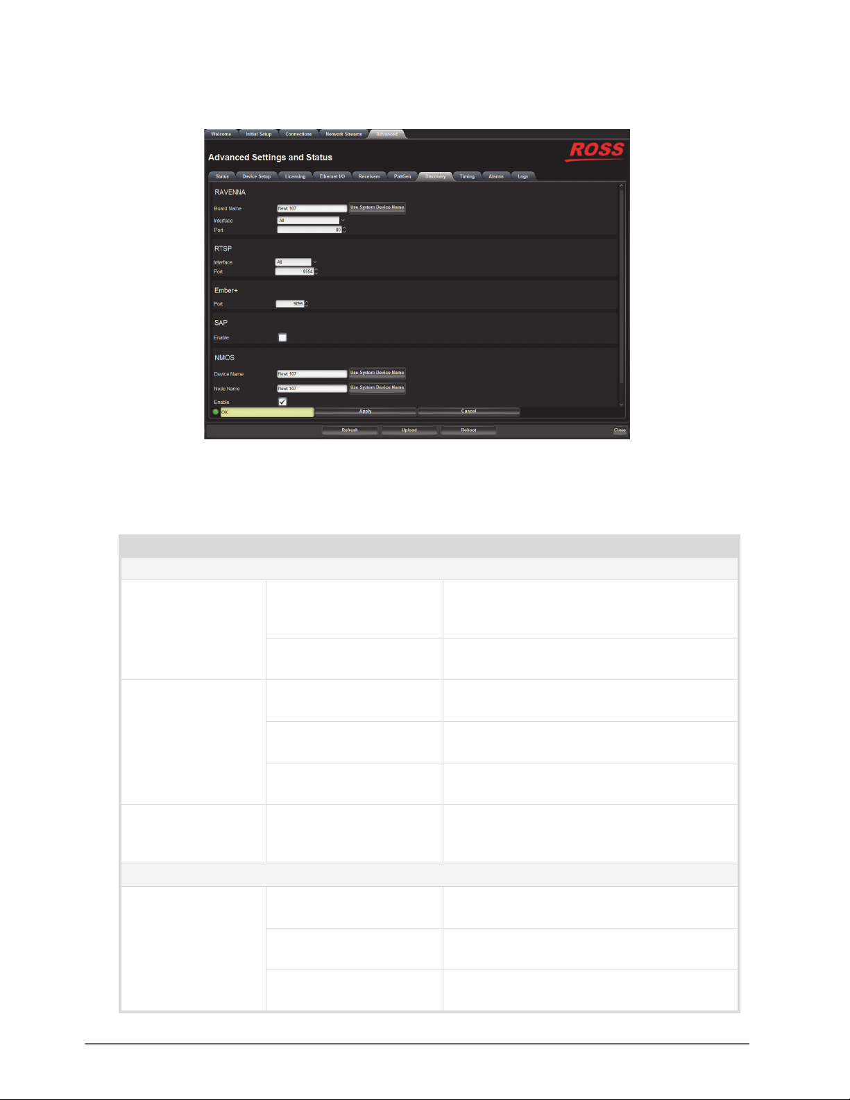
Discovery Tab
The Discovery tab provides options for configuring communications via third-party protocols.
Figure 17.16 Discovery Tab
Table 17.18 summarizes the options displayed in the Discovery tab.
Table 17.18 Discovery Tab
Item Parameters Description
RAVENNA
Board Name <text> Assigns a unique identifier for the NEWT-IPX
when communicating with RAVENNA-based
devices. The default name is
Ross-Newt.
Use System Device Name Applies the identifier to the NEWT-IPX as
provided by the master RAVENNA device
Interface Control RJ-45 The NEWT-IPX uses its CONTROL port for
RAVENNA communications
NET # The NEWT-IPX uses the specified NET port on
the NEWT-IPX for RAVENNA communications
All The NEWT-IPX accepts RAVENNA requests via
the CONTROL and all NET ports
Port # Specifies the communications port on the network
that the NEWT-IPX uses for RAVENNA
communications. The default is 80.
RTSP
Interface Control RJ-45 The NEWT-IPX uses its CONTROL port for RTSP
communications
NET # The NEWT-IPX uses the specified physical NET
port for RTSP communications
All The NEWT-IPX accepts RTSP requests via the
CONTROL and all NET ports
82 • DashBoard Interface Overview NEWT-IPX User Guide (v4.0)
Page 83
Table 17.18 Discovery Tab
Item Parameters Description
Port # Specifies the TCP port the protocol uses to send
and receive messages. The default is 8554.
Ember+
Port # Specifies the communications port on the network
that the NEWT-IPX uses for Ember+
communications. The default is 9095.
SAP
Enable Selected The NEWT will use the Session Announcement
Protocol (SAP) to broadcast multicast session
information
Cleared Disables this feature
NMOS
Device Name <text> Assigns a unique identifier for NEWT-IPX when
communicating with NMOS-based devices. The
default name is Ross NEWT
Use System Device Name Applies the identifier to the NEWT-IPX as
provided by the master NMOS device
Node Name <text> Name of the NMOS node being advertised. The
default name is Ross NEWT
Use System Device Name Applies the identifier to the NMOS mode as
provided by the master NMOS device
Enable Selected The NEWT-IPX is available as an NMOS device
Cleared The NEWT-IPX is not advertised as an NMOS
device
Interface Control RJ-45 The NEWT-IPX uses its CONTROL port for
NMOS communications
NET # The NEWT-IPX uses the specified NET port for
NMOS communications
All The NEWT-IPX accepts NMOS requests via the
CONTROL and all NET ports
SDP Port # Specifies the SDP HTTP port used to GET SDPS.
The default is 8081.
Timing Tab
The system timing options for the NEWT-IPX are organized into the following sub-tabs displayed on the left pane
of the Timing tab: PTP and Outputs.
NEWT-IPX User Guide (v4.0) DashBoard Interface Overview • 83
Page 84

Figure 17.17 Timing Tab — PTP
PTP Tab
Use the PTP tab to configure the PTP client settings for the NEWT-IPX. This is also where the NEWT-IPX is
displays an active Grandmaster.
Table 17.19 summarizes the options displayed in the PTP tab.
Table 17.19 Timing Tab — PTP
Item Parameters Description
Configuration
Slave Only Selected Defines the NEWT-IPX as a slave only device in
the system; the module cannot be used as a
Grandmaster or Master device
Cleared Enables the NEWT-IPX to be used as a
Grandmaster or Master device
Profile IEEE 1588 Default Specifies the NEWT-IPX timing uses IEE1588
standard
AES67 Media Specifies the NEWT-IPX timing uses AES67
Media standard
SMPTE ST 2059-2 Specifies the NEWT-IPX timing uses SMPTE ST
2059-2 standards.
This is the recommended setting.
Custom PTP Profile Selected The Domain, Priority1, Priority2, Role status,
Sync Interval, Announce Interval and Announce
Receipt Timeout fields can be edited to create a
custom PTP profile
Cleared The Domain, Priority1, Priority2, Role status,
Sync Interval, Announce Interval and Announce
Receipt Timeout fields are set to the default values
of the selected PTP Profile.
84 • DashBoard Interface Overview NEWT-IPX User Guide (v4.0)
Page 85

Table 17.19 Timing Tab — PTP
Item Parameters Description
Domain # Specifies that the NEWT-IPX is within the
specified group of clocks in your network
Priority1 # Assigns the first priority level to the NEWT-IPX
during a Grandmaster election where a value of:
• 1 is the highest priority
• 255 is the lowest priority
This menu is applicable when the Slave Only box
is not selected
Priority2 # Assigns the secondary priority level to the
NEWT-IPX during a Grandmaster election where a
value of:
• 1 is the highest priority
• 255 is the lowest priority
This menu is applicable when the Slave Only box
is not selected
NET #
Role Status # Indicates the role that the specified port is assigned
to in the network system
Sync Interval # Specifies how often the NET port on the
NEWT-IPX sends Sync messages
Announce Interval # Specifies how often the NET port on the
NEWT-IPX sends Announce messages
Announce Receipt
Timeout
# Controls how long the NET port on the
NEWT-IPX will wait before declaring the
Grandmaster absent and initiating a new election
Status (read-only)
Current Reference PTP SLAVE Specifies that the NEWT-IPX is a Slave; using that
system clock as the reference
INTERNAL Specifies that the NEWT-IPX is a Master; using
that system clock as the reference
System Status Locked Status of PTP on the system
Free run
Interface Status Locked Status of PTP on the interface
Acquiring
Fail
Status Details Reports details on detected Start of Frame (SOF)
errors
Local (read-only)
Local ID # Reports the ID number assigned to the NEWT-IPX
within the system
Mean Path Delay # Average time in nanoseconds it takes a packet to
traverse end to end from the PTP master
NEWT-IPX User Guide (v4.0) DashBoard Interface Overview • 85
Page 86
Table 17.19 Timing Tab — PTP
Item Parameters Description
Offset From Master # Correction time offset from the master in
nanoseconds
Min Delay Request
Interval
Grandmaster
# Specifies how long the NEWT-IPX will wait for a
delay request
Grandmaster ID # Reports the ID number assigned to the
Grandmaster within the system
Priority1 # Standard PTP fields used to determine who wins a
Priority2 #
PTP election
Clock Accuracy # Standard PTP field that states the accuracy of the
system clock on the system
Clock Class # Standard PTP field that states the class of the clock
used on the system
Outputs Tab
The Outputs tab automatically displays in the DashBoard window. The Outputs tab enables you to adjust the timing
of each SDI or HDMI output.
Table 17.20 summarizes the options displayed in the Outputs tab for each output.
Table 17.20 Timing Tab — Outputs
Item Parameters Description
Default Delay Selected The default for audio and video delays change
based on the audio packet time set on the device
If the audio packet time is 1ms (1000us) to default
video delay is 20000us and audio delay is 20000us
If the audio packet time is 125us to default video
delay is 2000us and audio delay is 2000us
Cleared NEWT-IPX applies the delay and offset settings in
the Outputs tab for the specified signal
Video Delay # Sets the video output delay relative to the selected
reference
Audio Offset # Changes the link offset values used when a
receiver is setup
Audio Delay
(read-only)
# Reports the audio output delay (Video Delay value
+ Audio Offset value) relative to the selected
reference
86 • DashBoard Interface Overview NEWT-IPX User Guide (v4.0)
Page 87
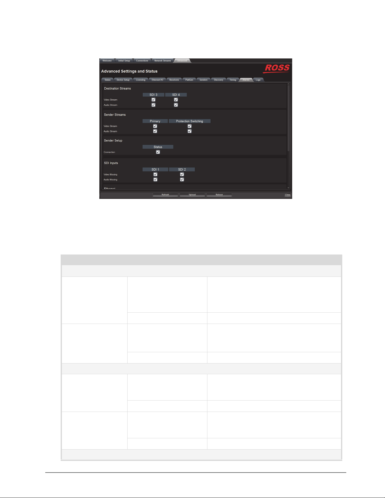
Alarms Tab
The Alarms tab enables you to manage the type of alarms the NEWT-IPX reports.
Figure 17.18 Alarms Tab — Two SDI Outputs Enabled
All alarms are enabled by default.
Table 17.21 summarizes the options displayed in the Alarms tab.
Table 17.21 Alarms Tab
Item Parameters Description
Destination Streams - SDI #
Video Stream Selected Enables the monitoring of the video signal of the
Audio Stream Selected Enables the monitoring of the audio stream.
Sender Streams - Primary, Protection Switching
Video Stream Selected The Advanced > Senders > Active Streams tab
a
stream
The status is reported in the Destinations area of
the Connections tab
Cleared Disables monitoring of this stream
The status is reported in the Destinations area of
the Connections tab.
Cleared Disables monitoring of this stream
monitors the configured video streams of the
NEWT-IPX
Cleared Disables monitoring of the sender video stream(s)
Audio Stream Selected The Advanced > Senders > Active Streams tab
monitors the configured audio streams of the
NEWT-IPX
Cleared Disables monitoring of the sender audio stream(s)
Sender Setup - Status
NEWT-IPX User Guide (v4.0) DashBoard Interface Overview • 87
Page 88
Table 17.21 Alarms Tab
Item Parameters Description
Connection Selected Changes made to the Advanced > Senders > Setup
Streams tab are reported in the Advanced > Status
> Device tab
Cleared Disables monitoring of the menus on the
Advanced > Senders tab. The Senders Status and
Changes field in the Advanced > Device tab does
not report any issues.
SDI Inputs - SDI #
Video Missing Selected The Advanced > SDI Inputs status fields report
when the video data on the specified SDI IN port is
not detected
Cleared Disables monitoring of the specified SDI IN port
Audio Missing Selected The Advanced > SDI Inputs status fields report
when the audio data on the specified SDI IN port is
not detected
Cleared Disables monitoring of this
Ethernet - Control RJ-45
Link Down Selected Enables the monitoring of the NEWT-IPX and
your facility network.
If a link is not detected, an error message displays
in the Ethernet > Link Status.
Link Down Cleared Disables monitoring of the communications
between the NEWT-IPX and your facility network
NET - NET #
Link Down Selected The corresponding field in the Ethernet I/O tab
reports when a link is not detected
Cleared Disables monitoring of the link status of the
specified NET port
PTP Status - System and Interface Status
PTP Clock Selected The System Clock Status field reports when the
connection to the PTP clock is lost
Cleared Disables monitoring of the PTP Clock status
a. This title changes from SDI to HDMI when the Operational Mode is set to UHD-over-IP to HDMI 2.0 Gateway.
Logs Tab
The Logs tab is organized into two sub-tabs: System Log and Captures.
System Log Tab
The System Log tab provides a system log interface that reports tasks, messages, and other operating information in
a table format. This is useful when troubleshooting with the help of Ross Technical Support.
Captures Tab
The Captures tab displays a list of log entries that were captured.
88 • DashBoard Interface Overview NEWT-IPX User Guide (v4.0)
Page 89

Table 17.22 summarizes the options displayed in the Captures tab.
Table 17.22 Logs Tab — Captures
Item Parameters Description
Name <text> Lists the recent debug, core, and PCAP files
currently available for download.
Select the Refresh button in the top right corner to
update the list.
Size (bytes) # Indicates the size of the file
Request Debug Creates a file that captures the log entries and
device status information of the NEWT-IPX
Duration [s] # Specifies the length of time (in seconds) to
perform a packet capture (PCAP)
Packet Capture Captures a PCAP file on the port specified in the
Interface menu
Interface eth0 Captures a PCAP file for the CONTROL port of
the NEWT-IPX
eth1 Captures a PCAP file for the NET 1 port of the
NEWT-IPX
eth2 Captures a PCAP file for the NET 2 port of the
NEWT-IPX
NEWT-IPX User Guide (v4.0) DashBoard Interface Overview • 89
Page 90

90 • DashBoard Interface Overview NEWT-IPX User Guide (v4.0)
Page 91

Technical Specifications
This chapter provides technical information for NEWT-IPX.
Specifications are subject to change without notice.
Supported Video Formats
Table 18.1 Technical Specifications — Supported Video Formats
Resolution (lines) SDI Mode HDMI Mode
720p 50Hz
720p 59.94Hz
720p 60Hz
1080i 50
1080i 59.94
1080i 60
1080p 50
1080p 59.94
1080p 60
2160p 25
2160p 29.94
2160p 30
2160p 50
2160p 59.94
2160p 60
NET 1, 2 Ports - Single Mode Connections
The NET ports on the NEWT-IPX can be populated with the following classes of modules.
Transmitter Port
Table 18.2 Technical Specifications — Single-mode Transmitter Port
Item Specifications
Port Type 10GBASE-LR
Signaling Speed 10.3125Gbps
Center Wavelength (typical) 1310nm
OMA Output Power (min.) -5.2dBm
Extinction Ratio (min.) 3.5dB
Side Mode Suppression Ratio SMSR (min.)
NEWT-IPX User Guide (v4.0) Technical Specifications • 91
30dB
Page 92

Table 18.2 Technical Specifications — Single-mode Transmitter Port
Item Specifications
Optical Return Loss (max.) 12dB
Link Length (max.) 10km
Connector Type
Receiver Port
Port Type 10GBASE-LR
Signaling Speed 10.3125Gbps
Center Wavelength 1310nm
Overload (min.) 0.5dBm
Receiver Sensitivity in OMA
(max.)
Stressed Receive Sensitivity OMA
(max.)
Link Length (max.) 10km
Connector Type
Single-mode fiber
Standard LC duplex fiber-optic connector
Table 18.3 Technical Specifications — Single-mode Receiver Port
Item Specifications
-12.6dBm
-10.3dBm
Single-mode fiber
Standard LC duplex fiber-optic connector
NET 1, 2 Ports - Multi-mode Connections
Transmitter
Table 18.4 Technical Specifications — Multi-mode Transmitter Port
Item Specifications
Port Type 10GBASE-SR
Signaling Speed 10.3125Gbps
Signaling Speed Variation from Normal +/-100ppm
Center Wavelength (typical) 850nm
Spectral Width RMS (max.) 0.65nm
Average Output Power (min.) -5dBm
Extinction Ratio (min.) 3
Optical Return Loss (max.) 12dB
Connector Type
Multi-mode fiber
Standard LC duplex fiber-optic connector
92 • Technical Specifications NEWT-IPX User Guide (v4.0)
Page 93
Receiver
Port Type 10GBASE-SR
Signaling Speed 10.3125Gbps
Table 18.5 Technical Specifications — Multi-mode Receiver Port
Item Specifications
Signaling Speed Variation from
Nominal
Center Wavelength 850nm
Overload (min.) 0dBm
Receiver Sensitivity in OMA
(max.)
Stressed Receive Sensitivity OMA
(max.)
Connector Type
Multi-mode Fiber Link Length
Table 18.6 Multi-mode Fiber Link Length
Fiber Type Category
FDDI 160 2-26
62.5um MMF
OM1 200 2-33
OM2 500 2-83
50um MMF
OM3 2000 2-300
+/-100ppm
-11dBm
-7.5dBm
Multi-mode fiber
Standard LC duplex fiber-optic connector
Minimum Modal Bandwidth @
850nm (MHz*km)
Operating
Range (m)
CONTROL Port
Table 18.7 Technical Specifications — Control Port
Item Specifications
Number of CONTROL Ports 1
Standards Accommodated 10/100/1000BASE-T
Connector Type RJ45
SDI Outputs Specifications
Table 18.8 Technical Specifications — SDI Outputs
Item Specifications
Number of Outputs Up to 4 (user configurable)
Standards Accommodated SMPTE ST 2082-1
Impedance 75ohm
NEWT-IPX User Guide (v4.0) Technical Specifications • 93
Page 94

Table 18.8 Technical Specifications — SDI Outputs
Item Specifications
Return Loss
Signal Level 800mV ±10%
DC Offset 0V ±50mV
>15dB to 1.485Gbps
>10dB to 2.97Gbps
Rise and Fall Time (20-80%)
Jitter
Overshoot <10%
Connection BNC
HDMI Port Specifications
The HDMI port is not implemented.
Table 18.9 Technical Specifications — HDMI Port
Item Specifications
Number of Outputs 1 (user configurable)
HDMI Version 2.0
Output Color Space YCbCr 4:2:2
Connector Type Type A
1.485Gbps: <270ps, <100ps difference
2.97Gbps: <135ps, <50ps difference
1.485Gbps: <1.0UI jitter measured 10Hz-100kHz, <0.2UI
above 100kHz
2.97Gbps: <1.0UI jitter measured 10Hz-100kHz, <0.3UI
above 100kHz
Power
Table 18.10 Technical Specifications — Power
Item Specifications
Required Voltage 15V
Current Consumption 1-2.67A
Total Power Consumption 15-40W (application dependent)
Environment
Table 18.11 Technical Specifications — Environment
Item Specifications
Maximum Ambient Temperature 40°C (104°F)
94 • Technical Specifications NEWT-IPX User Guide (v4.0)
Page 95

Dimensions
Physical Dimensions 4.98” x 6.75” x 1.63”
Weight 815g (1.8lb)
Table 18.12 Technical Specifications — Dimensions
Item Specifications
NEWT-IPX User Guide (v4.0) Technical Specifications • 95
Page 96

96 • Technical Specifications NEWT-IPX User Guide (v4.0)
Page 97

Service Information
This chapter provides information on the warranty and repair policy for your NEWT-IPX.
Troubleshooting Checklist
Routine maintenance to this Ross product is not required. In the event of problems with your NEWT-IPX, the
following basic troubleshooting checklist may help identify the source of the problem. If the NEWT-IPX still does
not appear to be working properly after checking all possible causes, please contact your Ross products distributor,
or the Technical Support department at the numbers listed under the “Contacting Technical Support” on page 12.
1. Visual Review — Performing a quick visual check may reveal many problems, such as connectors not properly
seated or loose cables. Check the NEWT-IPX and any associated peripheral equipment for signs of trouble.
2. Power Check — Verify the PWR LED on the NEWT-IPX chassis for the presence of power. If the PWR LED
is not illuminated, verify that the power cable is connected to a power source and that power is available at the
power main. If the PWR LED is still not illuminated, replace the power supply with one that is verified to
work.
3. Input Signal Status — Verify that source equipment is operating correctly and that a valid signal is supplied.
4. Output Signal Path — Verify that destination equipment is operating correctly and receiving a valid signal.
5. Module Exchange — Exchanging a suspect module with a module that is known to be working correctly is an
efficient method for localizing problems to individual modules.
6. Re-load the Factory Defaults — If the module appears to be working and reports no errors, but is not
generating an active picture or outputs black, restoring the default factory configuration may fix the problem.
Contact Ross Technical Support if the NEWT-IPX is non-responsive after an upgrade.
Warranty and Repair Policy
The NEWT-IPX is warranted to be free of any defect with respect to performance, quality, reliability, and
workmanship for a period of ONE (1) year from the date of delivery to the customer. In the event that your
NEWT-IPX proves to be defective in any way during this warranty period, Ross Video Limited reserves the right to
repair or replace this piece of equipment with a unit of equal or superior performance characteristics.
Should you find that this NEWT-IPX has failed after your warranty period has expired, we will repair your
defective product should suitable replacement components be available. You, the owner, will bear any labor and/or
part costs incurred in the repair or refurbishment of said equipment beyond the ONE (1) year warranty period.
In no event shall Ross Video Limited be liable for direct, indirect, special, incidental, or consequential damages
(including loss of profits) incurred by the use of this product. Implied warranties are expressly limited to the
duration of this warranty.
This NEWT-IPX User Guide provides all pertinent information for the safe installation and operation of your
NEWT-IPX. Ross Video policy dictates that all repairs to the NEWT-IPX are to be conducted only by an authorized
Ross Video Limited factory representative. Therefore, any unauthorized attempt to repair this product, by anyone
other than an authorized Ross Video Limited factory representative, will automatically void the warranty. Please
contact Ross Video Technical Support for more information.
In Case of Problems
Should any problem arise with your NEWT-IPX, please contact the Ross Video Technical Support Department.
(Contact information is supplied at in the section “Contacting Technical Support” on page 12.)
A Return Material Authorization number (RMA) will be issued to you, as well as specific shipping instructions,
should you wish our factory to repair your NEWT-IPX. If required, a temporary replacement will be made available
NEWT-IPX User Guide (v4.0) Service Information • 97
Page 98

at a nominal charge. Any shipping costs incurred will be the responsibility of you, the customer. All products
shipped to you from Ross Video Limited will be shipped collect.
The Ross Video Technical Support Department will continue to provide advice on any product manufactured by
Ross Video Limited, beyond the warranty period without charge, for the life of the equipment.
98 • Service Information NEWT-IPX User Guide (v4.0)
Page 99

Software Licenses
This chapter provides third-party software license information for your NEWT-IPX. This product includes multiple
software components which are individually licensed under one or more of the following licenses included in this
chapter.
BSD
Copyright (c) 1991,1993, The Regents of the University of California. All rights reserved.
This code is derived from software contributed to Berkeley by Kenneth Almquist.
Redistribution and use in source and binary forms, with or without modification, are permitted provided that the following conditions are met:
1. Redistributions of source code must retain the above copyright notice, this list of conditions and the following disclaimer.
2. Redistributions in binary form must reproduce the above copyright notice, this list of conditions and the following disclaimer in the documentation and/or other
materials provided with the distribution.
3. <BSD Advertising Clause omitted per the July 22, 1999 licensing change ftp://ftp.cs.berkeley.edu/pub/4bsd/README.Impt.License.Change> California, Berke-
ley and its contributors.
4. Neither the name of the University nor the names of its contributors may be used to endorse or promote products derived from this software without specific prior
written permission.
THIS SOFTWARE IS PROVIDED BY THE REGENTS AND CONTRIBUTORS ``AS IS'' AND ANY EXPRESS OR IMPLIED WARRANTIES, INCLUDING,
BUT NOT LIMITED TO, THE IMPLIED WARRANTIES OF MERCHANTABILITY AND FITNESS FOR A PARTICULAR PURPOSE ARE DISCLAIMED. IN
NO EVENT SHALL THE REGENTS OR CONTRIBUTORS BE LIABLE FOR ANY DIRECT, INDIRECT, INCIDENTAL, SPECIAL, EXEMPLARY, OR CONSEQUENTIAL DAMAGES (INCLUDING, BUT NOT LIMITED TO, PROCUREMENT OF SUBSTITUTE GOODS OR SERVICES; LOSS OF USE, DATA, OR
PROFITS; OR BUSINESS INTERRUPTION) HOWEVER CAUSED AND ON ANY THEORY OF LIABILITY, WHETHER IN CONTRACT, STRICT LIABILITY, OR TORT (INCLUDING NEGLIGENCE OR OTHERWISE) ARISING IN ANY WAY OUT OF THE USE OF THIS SOFTWARE, EVEN IF ADVISED OF
THE POSSIBILITY OF SUCH DAMAGE.
Dual GPL
Portions of this software are copyright (C) 1996-2002 The FreeType Project (www.freetype.org). All rights reserved.
This project is also covered under the GPL v2.
GPL
GNU GENERAL PUBLIC LICENSE
Copyright (C) 2007 Free Software Foundation, Inc. <http://fsf.org/>
The GNU General Public License is a free, copyleft license for software and other kinds of works.
The licenses for most software and other practical works are designed to take away your freedom to share and change the works. By contrast, the GNU General Public License is intended to guarantee your freedom to share and change all versions of a program--to make sure it remains free software for all its users. We, the Free
Software Foundation, use the GNU General Public License for most of our software; it applies also to any other work released this way by its authors. You can apply
it to your programs, too.
When we speak of free software, we are referring to freedom, not price. Our General Public Licenses are designed to make sure that you have the freedom to distribute copies of free software (and charge for them if you wish), that you receive source code or can get it if you want it, that you can change the software or use pieces
of it in new free programs, and that you know you can do these things.
To protect your rights, we need to prevent others from denying you these rights or asking you to surrender the rights. Therefore, you have certain responsibilities if
you distribute copies of the software, or if you modify it: responsibilities to respect the freedom of others.
For example, if you distribute copies of such a program, whether gratis or for a fee, you must pass on to the recipients the same freedoms that you received. You must
make sure that they, too, receive or can get the source code. And you must show them these terms so they know their rights.
Developers that use the GNU GPL protect your rights with two steps: (1) assert copyright on the software, and (2) offer you this License giving you legal permission
to copy, distribute and/or modify it.
For the developers' and authors' protection, the GPL clearly explains that there is no warranty for this free software. For both users' and authors' sake, the GPL
requires that modified versions be marked as changed, so that their problems will not be attributed erroneously to authors of previous versions.
Some devices are designed to deny users access to install or run modified versions of the software inside them, although the manufacturer can do so. This is fundamentally incompatible with the aim of protecting users' freedom to change the software. The systematic pattern of such abuse occurs in the area of products for individuals to use, which is precisely where it is most unacceptable. Therefore, we have designed this version of the GPL to prohibit the practice for those products. If
Version 3, 29 June 2007
Preamble
NEWT-IPX User Guide (v4.0) Software Licenses • 99
Page 100

such problems arise substantially in other domains, we stand ready to extend this provision to those domains in future versions of the GPL, as needed to protect the
freedom of users.
Finally, every program is threatened constantly by software patents. States should not allow patents to restrict development and use of software on general-purpose
computers, but in those that do, we wish to avoid the special danger that patents applied to a free program could make it effectively proprietary. To prevent this, the
GPL assures that patents cannot be used to render the program non-free.
The precise terms and conditions for copying, distribution and modification follow.
TERMS AND CONDITIONS
0. Definitions.
"This License" refers to version 3 of the GNU General Public License.
"Copyright" also means copyright-like laws that apply to other kinds of works, such as semiconductor masks.
"The Program" refers to any copyrightable work licensed under this License. Each licensee is addressed as "you". "Licensees" and "recipients" may be individuals or
organizations.
To "modify" a work means to copy from or adapt all or part of the work in a fashion requiring copyright permission, other than the making of an exact copy. The
resulting work is called a "modified version" of the earlier work or a work "based on" the earlier work.
A "covered work" means either the unmodified Program or a work based on the Program.
To "propagate" a work means to do anything with it that, without permission, would make you directly or secondarily liable for infringement under applicable copyright law, except executing it on a computer or modifying a private copy. Propagation includes copying, distribution (with or without modification), making available
to the public, and in some countries other activities as well.
To "convey" a work means any kind of propagation that enables other parties to make or receive copies. Mere interaction with a user through a computer network,
with no transfer of a copy, is not conveying.
An interactive user interface displays "Appropriate Legal Notices" to the extent that it includes a convenient and prominently visible feature that (1) displays an
appropriate copyright notice, and (2) tells the user that there is no warranty for the work (except to the extent that warranties are provided), that licensees may convey
the work under this License, and how to view a copy of this License. If the interface presents a list of user commands or options, such as a menu, a prominent item in
the list meets this criterion.
1. Source Code.
The "source code" for a work means the preferred form of the work for making modifications to it. "Object code" means any non-source form of a work.
A "Standard Interface" means an interface that either is an official standard defined by a recognized standards body, or, in the case of interfaces specified for a particular programming language, one that is widely used among developers working in that language.
The "System Libraries" of an executable work include anything, other than the work as a whole, that (a) is included in the normal form of packaging a Major Component, but which is not part of that Major Component, and (b) serves only to enable use of the work with that Major Component, or to implement a Standard Interface
for which an implementation is available to the public in sourc
dow system, and so on) of the specific operating system (if any) on which the executable work runs, or a compiler used to produce the work, or an object code interpreter used to run it.
The "Corresponding Source" for a work in object code form means all the source code needed to generate, install, and (for an executable work) run the object code
and to modify the work, including scripts to control those activities. However, it does not include the work's System Libraries, or general-purpose tools or generally
available free programs which are used unmodified in performing those activities but which are not part of the work. For example, Corresponding Source includes
interface definition files associated with source files for the work, and the source code for shared libraries and dynamically linked subprograms that the work is specifically designed to require, such as by intimate data communication or control flow between those subprograms and other parts of the work.
The Corresponding Source need not include anything that users can regenerate automatically from other parts of the Corresponding Source.
The Corresponding Source for a work in source code form is that same work.
2. Basic Permissions.
All rights granted under this License are granted for the term of copyright on the Program, and are irrevocable provided the stated conditions are met. This License
explicitly affirms your unlimited permission to run the unmodified Program. The output from running a covered work is covered by this License only if the output,
given its content, constitutes a covered work. This License acknowledges your rights of fair use or other equivalent, as provided by copyright law.
You may make, run and propagate covered works that you do not convey, without conditions so long as your license otherwise remains in force. You may convey
covered works to others for the sole purpose of having them make modifications exclusively for you, or provide you with facilities for running those works, provided
that you comply with the terms of this License in conveying all material for which you do not control copyright. Those thus making or running the covered works for
you must do so exclusively on your behalf, under your direction and control, on terms that prohibit them from making any copies of your copyrighted material outside their relationship with you.
Conveying under any other circumstances is permitted solely under the conditions stated below. Sublicensing is not allowed; section 10 makes it unnecessary.
3. Protecting Users' Legal Rights From Anti-Circumvention Law.
No covered work shall be deemed part of an effective technological measure under any applicable law fulfilling obligations under article 11 of the WIPO copyright
treaty adopted on 20 December 1996, or similar laws prohibiting or restricting circumvention of such measures.
When you convey a covered work, you waive any legal power to forbid circumvention of technological measures to the extent such circumvention is effected by
exercising rights under this License with respect to the covered work, and you disclaim any intention to limit operation or mo
enforcing, against the work's users, your or third parties' legal rights to forbid circumvention of technological measures.
e code form. A "Major Component", in this context, means a major essential component (kernel, win-
dification of the work as a means of
100 • Software Licenses NEWT-IPX User Guide (v4.0)
 Loading...