

ROSIERES RBVSI985IN User Manual

INSTALLATION AND
CONTENT
INTRODUCTION
SAFETY PRECAUTION
SPECIFICATION
INSTALLATION
DESCRIPTION OF COMPONENTS
OPERATION
MAINTENANCE
TROUBLESHOOTING
CONFORMITY WITH DIRECTIVES
ENVIRONMENTAL PROTECTION
4-5
USER’S MANUAL
2
2
3
6
6
7
8
8
9
1

INTRODUCTION
Thank you for choosing this cooker hood.
This instruction manual is designed to provide you with all required
instructions related to the installation, use and maintenance of the appliance.
In order to operate the unit correctly and safety, please read this instruction
manual carefully before installation and usage.
The cooker hood uses high quality materials, and is made with a streamlined
design. Equipped with large power electric motor and centrifugal fan, it also
provides strong suction power, low noise operation, non-stick grease filter and
easy assembly installation.
SAFETY PRECAUTION
□ Never let the children operate the machine.
□ The cooker hood is for home use only, not suitable for barbecue, roast
shop and other commercial purpose.
□ The cooker hood and its filter should be clean regularly in order to
keep in good working condition.
□ Clean the cooker hood according to the instruction manual and keep
the unit from danger of burning.
□ Forbid the direct baking from the gas cooker.
□ Please keep the kitchen room a good convection.
□ Before connecting this appliance check that the power supply cord is
not damaged. A damage supply cord must be replaced by qualified
service personnel only.
□ There shall be adequate ventilation of the room when the range hood
is used at the same time as appliances burning gas or other fuels;
□ The air must not be discharged into a flue that is used for exhausting
fumes from appliances burning gas or other fuels;
□ Regulations concerning the discharge of air have to be fulfilled.
□ This appliance if not intended for use by persons(including children)
with reduced physical, sensory or mental capabilities, or lack of
experience and knowledge, unless they have been given supervision or
instruction concerning use of the appliance by a person slide for their
safety.
□ Children should be supervised to ensure that they do not play with the
appliance.
□ Do not flame under the range hood.
□ The range hood is not intended to be installed over a hob having more
than four hob elements
□ Only plug this unit into a properly earthed outlet. If in doubt seek
advice from a suitably qualified engineer.
□ Failure to follow these instructions can result in death, fire, or
electrical shock.
Electrical Shock Hazard
2
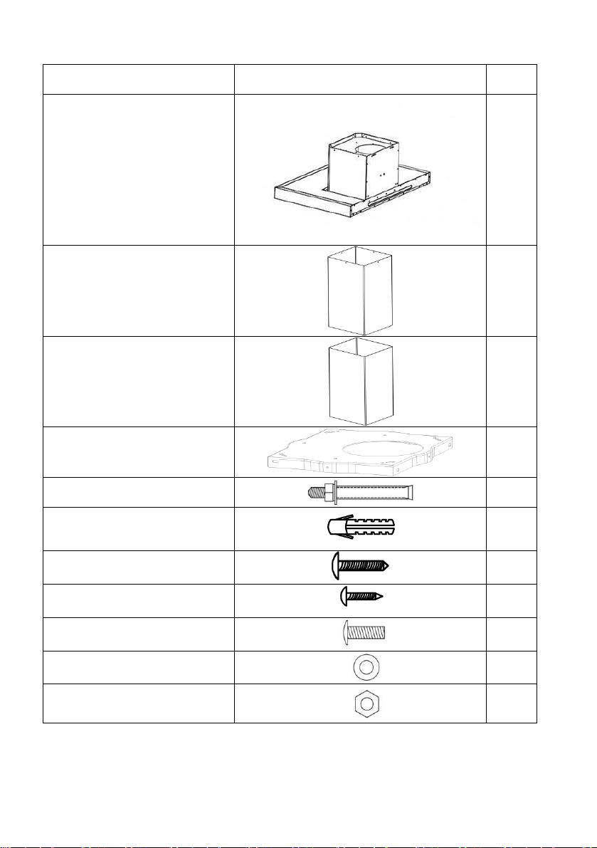
Standard Installation Accessories List
Spec.
Illustration Picture
Qty
Casing
1
Upper Chimney 600mm
1
Lower Chimney 600mm
1
Hanging Board
1
Screws M6×60
8
φ8 Rawl Plugs
φ8×φ6 white color
11
Screws
ST6.0×40
11
φ7.2 Screws
ST4.0×8
4
Screws M5x12
40
Washers
16
Nuts
16
3
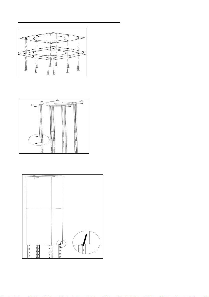
CEILING MOUNTING INSTALLATION
1)Position the hanging plate on the
ceiling and then mark the position of the
screw holes.
The hanging plate should be securely fixed
to the ceiling,
11 x ST6 (40 mm)screws for wooden
ceiling
8 x expansion bolts for cement ceiling
2) Fix the angle bars to the hanging plate,
using the 8 x M5 screws.
3) Extend the angle bars to the repuired
height and then fix them in position using
the 16 x M5 screws and nuts with metal
washers.
IMPORTANT: The angle bars must have an overlap of AT LEAST 100
mm.
4) If your cooker hood is going to
be used in extraction mode, then
you should connect the ducting
hose to the ceiling adaptor at this
point.
Fix the upper chimney section to
the hanging plate, using the 4 x
self tapping screws.
Slide the lower chimney section
onto the angle bars and raise it
until it sits just below the upper
chimney section.
4
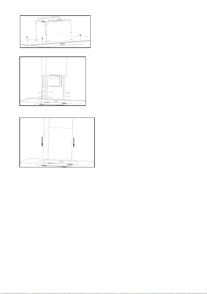
5) If the glass canopy has not been
pre-assembled by the factory, then it
should be fixed to the top of the main
body of the cooker hood at this stage.
6) Lift the main body of the cooker
hood onto the angle bar and then fix it
into position using the 16 x M5 screws.
IMPORTANT: This stage of the
installation process MUST be
completed by two people.
IMPORTANT: The 16 x M5 screws
MUST be securely tightened.
7) If you are going to be using the
hood in
extraction mode, you should fix the
ducting
hose to the spigot.
The electrical connection must correspond to the electrical
repuirement noted on the rating plate, which is placed inside the
cooker hood. The appliance should now be connected to the
electrical supply.
Check that the appliance is operating correctly by selecting each speed
and switching the light bulbs on and off.
Remove the hanging hook and then slide the lower chimney section
downwards, until it rests against the main body of the cooker hood.
Use a stainless steel cleaner and polish on the stainless steel sections of
the appliance.
If you are using the appliance in recirculation mode, then you
should now fit the carbon filter.
5
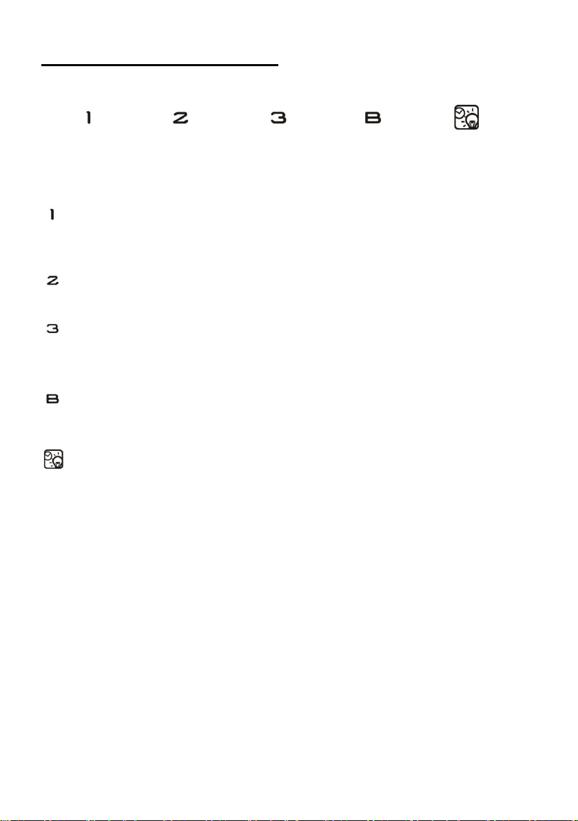
DESCRIPTION OF COMPONENTS
STANDBY MODE.
After plug in, all lighting, system in STANDBY MODE.
Low Speed button
It’s used for Ventilation on the kitchen. It is suitable for simmering and
cooking which do not make much steam.
Medium Speed button
Airflow speed is ideally for ventilation in standard cooking operation.
High Speed button
When high density of smoke or steam produced, press high-speed button
for high effective ventilation.
Booster button
Depress this button to enter into highest speed and again to turn off motor.
Light & Timer button
Short press for lamp control.
Keep pressing the light/timer icon for 2-3 seconds to active the quick timer
function.
During the count down, you can press light/timer icon one more time to
stop the quick timer function.
Remark: other button (speed, light) can still workable during quick timer
function.
6
 Loading...