

Rosieres RBVS685TIN User Manual
ENGLIS
H
INSTALLATION AND USER’S MANUAL
FRENC
H
NOTICE D’INSTALLATION ET
D’UTILISATION
ITALIAN
MANUALE D’ISTRUZIONE
1

INSTALLATION AND USER’S MANUAL
CONTENT
INTRODUCTION 03
SAFETY PRECAUTION 03
SPECIFICATION 05
INSTALLATION (VENT OUTSIDE) 06
INSTALLATION (VENT INSIDE) 10
DESCRIPTION OF COMPONENTS 11
OPERATION 11
MAINTENANCE 13
TROBULESHOOTING 14
CONFORMITY WITH DIRECTIVES 15
ENVIRONMENTAL PROTECTION 15
2

INTRODUCTION
Thank you for choosing this cooker hood.
This instruction manual is designed to provide you with all required
instructions related to the installation, use and maintenance of the appliance.
In order to operate the unit correctly and safety, please read this instruction
manual carefully before installation and usage.
The cooker hood uses high quality materials, and is made with a streamlined
design. Equipped with large power electric motor and centrifugal fan, it also
provides strong suction power, low noise operation, non-stick grease filter and
easy assembly installation.
SAFETY PRECAUTION
Never let the children operate the machine.
The cooker hood is for home use only, not suitable for barbecue, roast
shop and other commercial purpose.
The cooker hood and its filter should be clean regularly in order to
keep in good working condition.
Clean the cooker hood according to the instruction manual and keep
the unit from danger of burning.
Forbid the direct baking from the gas cooker.
Please keep the kitchen room a good convection.
Before connecting this appliance check that the power supply cord is
not damaged. A damage supply cord must be replaced by qualified
service personnel only.
There shall be adequate ventilation of the room when the range hood
is used at the same time as appliances burning gas or other fuels;
The air must not be discharged into a flue that is used for exhausting
fumes from appliances burning gas or other fuels;
•
Regulations concerning the discharge of air have to be fulfilled.
•
•
Children should be supervised to ensure that they do not play with the
appliance.
•
Do not flambé under the range hood.
•
The range hood is not intended to be installed over a hob having more
than four hob elements
Electrical Shock Hazard
Only plug this unit into a properly earthed outlet. If in doubt seek
advice from a suitably qualified engineer.
Failure to follow these instructions can result in death, fire, or
electrical shock.
3

4
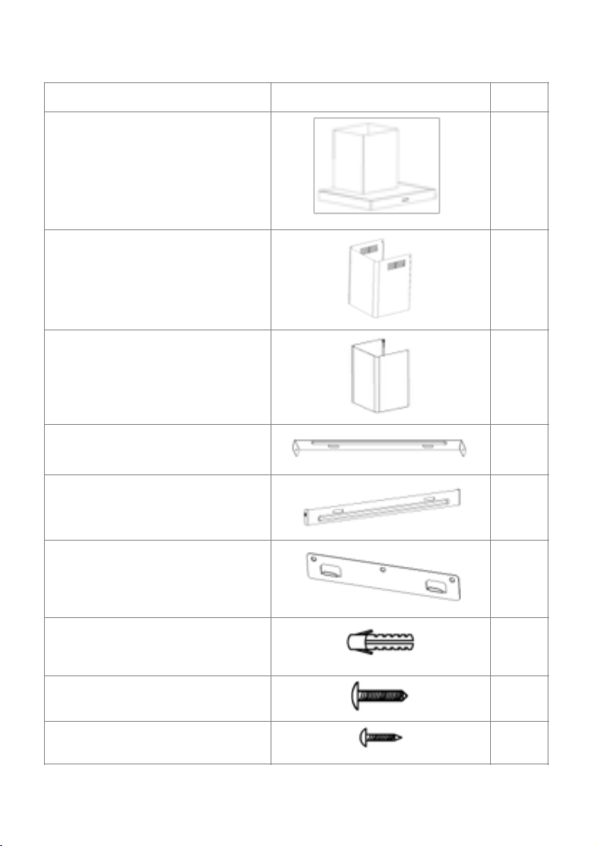
Standard Installation Accessories List
Spec.
Illustration Picture
Qty
Casing
1
Upper Chimney
1
Lower Chimney
1
Lower chimney bracket
1
Upper chimney bracket
1
Hanging Board
1
φ8 rawl plugs
φ8×φ6 white color
9
Screws
ST4.0×30
9
φ7.2screws
ST4.0×8
2
#
#
#
#
#
#
#
#
!
5
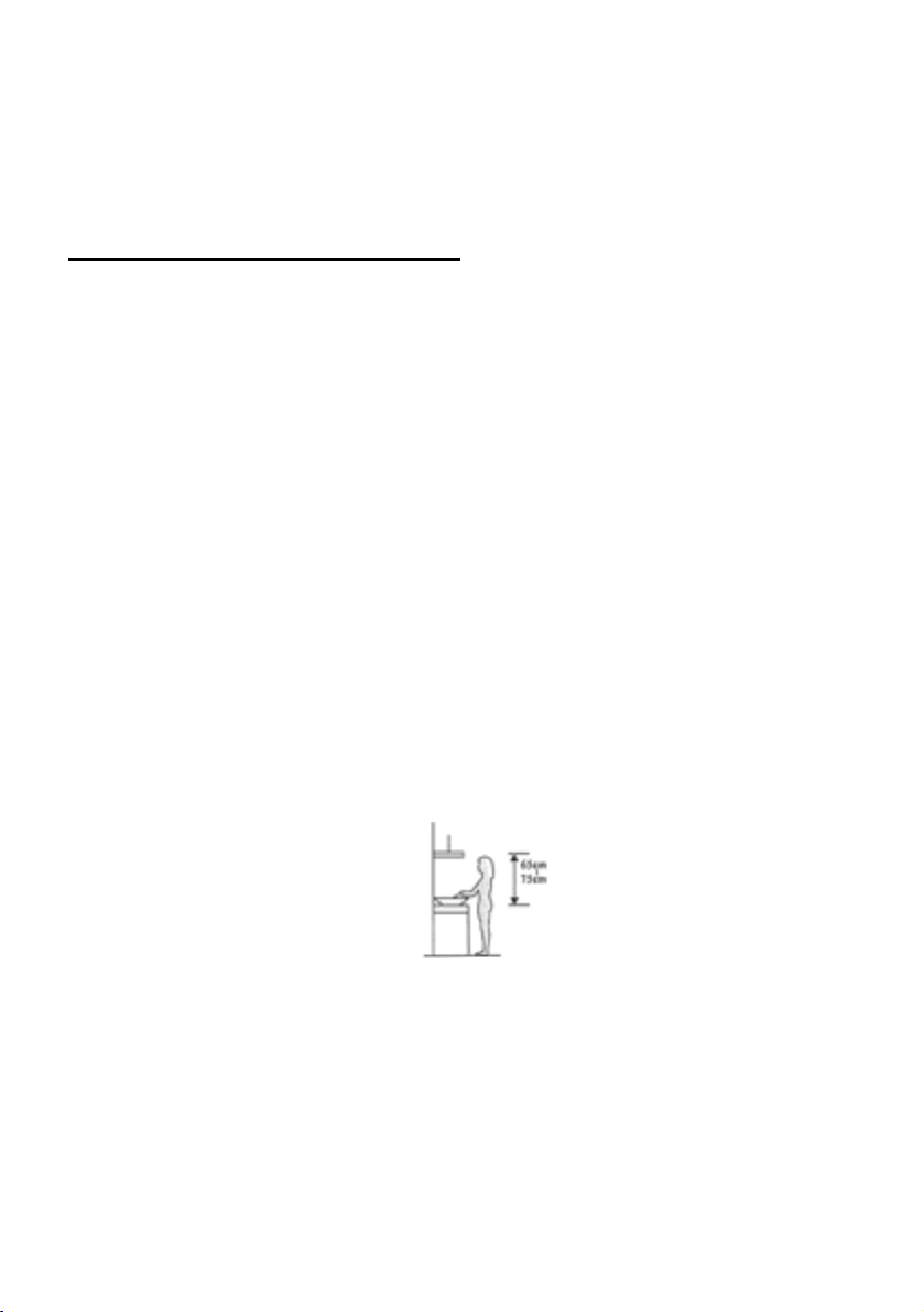
INSTALLATION (wall mounting)
If you have an outlet to the outside, your cooker hood can be connected as
below picture by means of an extraction duct (enamel, aluminum, flexible pipe
non flammabe with an interior diameter of 150mm)
1. Before installation, turn the unit off and unplug it from the outlet.
2. The cooker hood should be placed at a distance of 65~75cm above
the cooking plane for best effect.
#
3. Drill 3 x 8mm holes to accommodate the bracket. Screw and tighten
the bracket onto the wall with the screws provided.
Wall plug
6

Wall bracket
107.5
mm
Screw(4mm x 30mm)
7

4. Leave up the cooker hood and hang onto the wall bracket hook.
Cooker hook
Wall
bracket
#
5. Fix the one-way-valve to the air outlet of the cooker hood. Then,
attached the exhaust pipe onto the one-way-valve as shown below.
Exhaust pipe
Cooker hood
8
6.
i. Place the glass in appropriate position on the top the cooker
hood.
ii. Fix with 4 screws and washer. In order to avoid the glass
cracking, please do not tighten the screws too strongly.
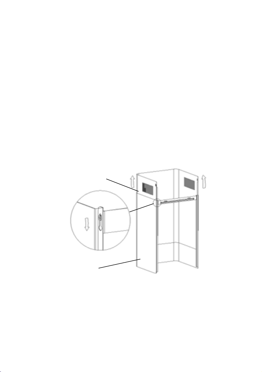
i. By Put the inner chimney into outer chimney .Then pulling out
the inner chimney upwards. Adjust to reach the height required.
ii. Sliding the chimney to adjust the chimney height. When the
height you required is reached, then hang the fixing hole to the
fixing screws as showed in below pictures.
Inner chimney
Outer
chimney
9

8.
i. Drill 2 x 8mm holes to accommodate the plate II. Screw and
tighten the plate II onto the wall with 2 screws provided.
ii. Assembly the chimney onto the unit and fix it with 2 screws.
Plate II
Wall plug
Screw
4mm x 8mm
Screw
(4mm x 30mm)!
10
INSTALLATION (VENT INSIDE)
If you do not have an outlet to the outside, exhaust pipe is not required and
the installation is similar to the one show in section “INSTALLATION (VENT
OUTSIDE)”.
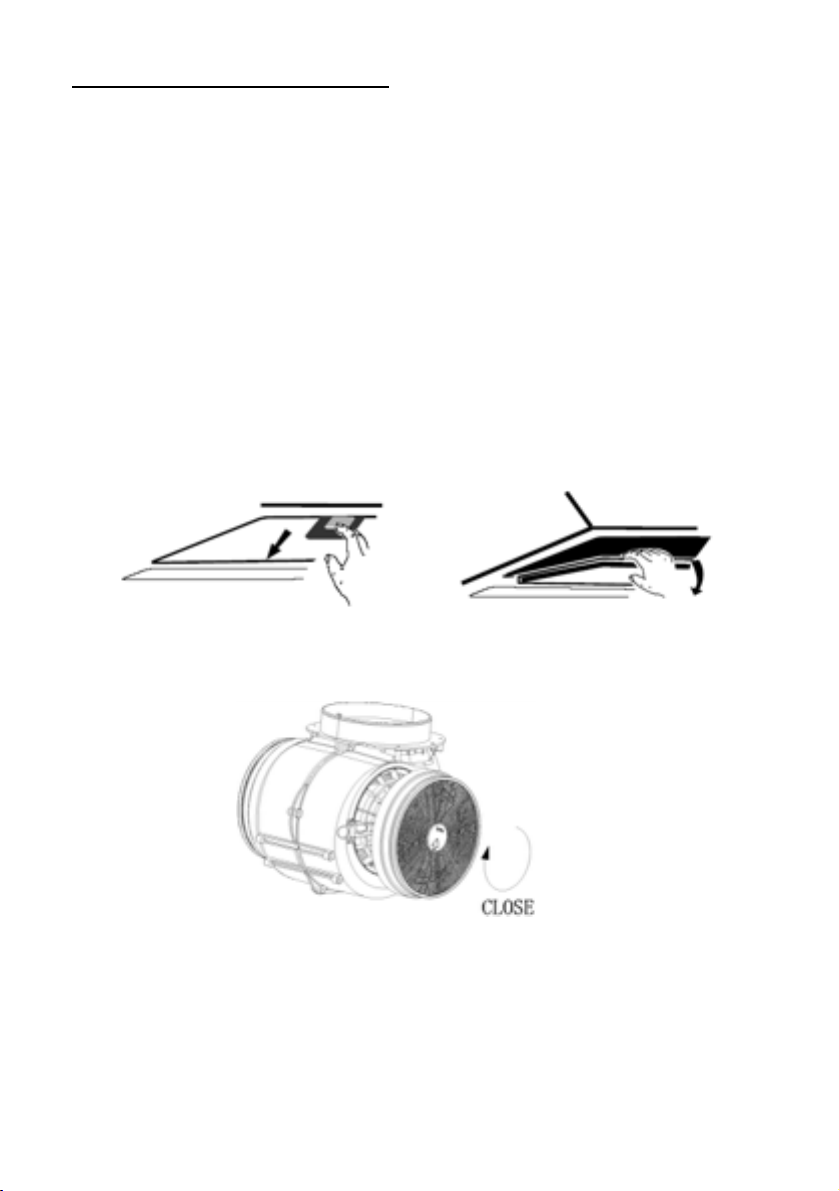
Activated carbon filter can be used to trap odors.
In order to install the activated carbon filter, the grease filter should be
detached first. Press the lock and pull it downward.
#
Plug the activated carbon filter into the unit and turn it in clockwise direction.
Repeat the same on the other side.
NOTE:
o Make sure the filter is securely locked. Otherwise, it would loosen and
cause dangerous.
o When activated carbon filter attached, the suction power will be
lowere!
11

DESCRIPTION OF COMPONENTS
#
OPERATION
Low Speed button ! 1
It’s used for Ventilation on the kitchen. It is suitable for simmering and cooking
which do not make much steam.
Medium Speed button ! 2
Airflow speed is ideally for ventilation in standard cooking operation.
High Speed button ! 3
When high density of smoke or steam produced, press high-speed button for
highest effective ventilation.
Light button !
NOTE: If Low / Medium / High speed buttons are press at the same time, the
unit will only operate at the highest speed.
12

#
ON/OFF button !
Pressing 1-2 seconds to switch on/off the cooker hood.
Low Speed button !
It’s used for Ventilation on the kitchen. It is suitable for simmering and cooking
which do not make much steam.
Medium Speed button !
Airflow speed is ideally for ventilation in standard cooking operation.
High Speed button !
When high density of smoke or steam produced, press high-speed button for
highest effective ventilation.
Light button #
Short press the light/timer button ( 1 second) to switch on or switch off the
light.
Quick Timer#
.Keep pressing the Light/timer button for 2-3 seconds to switch on the quick
timer.
The working speed button will become flashing, the quick timer will last for 5
seconds.
When the count down finish, there will be ‘bit’ sounds for 5 seconds.
To cancel the quick timer, press Light/Timer button again or press the ON/OFF
button.
13

MAINTENANCE
Before cleaning switch the unit off and pull out the plug.
I. Regular Cleaning
Use a soft cloth moistened with hand-warm mildly soapy water or
household cleaning detergent. Never use metal pads, chemical, abrasive
material or stiff brush to clean the unit.
II. Monthly Cleaning for Grease Filter
ESSENTIAL: Clean the filter every month can prevent any risk of fire.
The filter collects grease, smoke and dust…... so the filter is directly
affecting the efficiency of the cooker hood. If not cleaned, the grease
residue (potential flammable) will saturate on the filter. Clean it with
household cleaning detergent.
III. Annual Cleaning for Activated Carbon Filter
Apply SOLELY to unit that installed as a recirculation unit (not vented to
the outside). This filter traps odors and must be replaced at least once a
year
depending on how frequent the cooker hood used.
IV. Changing a light bulb
Remove the screws on the glass, take off the hood glass. Find the
bulb that requires replacement, you will find it located in the light
fixture which is inside the exposed section of the canopy.
#
Disconnect the light wiring point and remove the bulb holders and
wiring from the hood. Important: It’s not possible to replace the bulbs
individually, it will be necessary to obtain the bulbs, bulb holders and
wiring as a complete part. (LED light: G4, MAX 1.5W)
Fit the replacement bulbs, bulb holders and wiring in the same
manners as the originals. Then reconnect the light wiring point.
14

Refit the hood glass and fasten the glass screws. Make sure the screws
are fully tightened.
TROBULESHOOTING
CUSTOMER ASSISTANCE SERVICE
If you cannot identify the cause of the operating anomaly, switch off the
appliance and contact the Assistance Service.
PRODUCT SERIAL NUMBER. Where can I find it?
It is important you to inform the Assistance Service of your product code
and its serial number (a 16 character code which begins with the number
3); this can be found on the guarantee certificate or on the data plate
located on the appliance.
It will help to avoid wasted journeys to technicians, thereby (and most
significantly) saving the corresponding callout charges.
This appliance is marked according to the European directive
2012/19/EU on Waste Electrical and Electronic Equipment
(WEEE).
Light on,
but fan
does not
The fan
Switch off the unit and repair
by qualified service
Both light
and fan do
not work
Halogen light bulb
Replace the bulb with
Serious
Vibration
of the
unit
The fan
blade is
Switch of the unit and repair
by qualified service
The fan motor is
not fixed tightly.
Switch off the unit and repair
by qualified service
The unit is not hung
properly on the
Take down the unit and
check whether the bracket
is in proper location.
Suction
performan
ce not
Too long distance
between the unit
and the cooking
Readjust the distance to
65-75cm
15
 Loading...