

World Class 3000 O2 Analyzer with IFT 3000 Intelligent Field Transmitter-Rev 4.0
Table of contents
 Loading...
Rosemount World Class 3000 O2 Analyzer with IFT 3000 Intelligent Field Transmitter-Rev 4.0 Manuals & Guides

WORLD CLASS 3000
OXYGEN ANALYZER
WITH IFT 3000
INTELLIGENT
FIELD TRANSMITTER
Instruction Bulletin IB-106-300NH Rev. 4.0
World Class 3000 Probe
Part No. ____________________
Serial No. ____________________
Order No. ____________________
IFT 3000
Part No. ____________________
Serial No. ____________________
Order No. ____________________
HPS 3000
Part No. ____________________
Serial No. ____________________
Order No. ____________________
MPS 3000
Part No. ____________________
Serial No. ____________________
Order No. ____________________


HIGHLIGHTS OF CHANGES
Effective May, 1999 Rev. 4
PAGE SUMMARY
xvii-xxiii Added new Quick Start Guide.
3-1 Added Section 3, Setup.
4-1 Removed calibration information from Operation section, and created Section 4, Calibration.
6-2 Expanded explanations of IFT status codes.
Section 6 Added new troubleshooting procedures.
IB-106-300NH


ROSEMOUNT WARRANTY
Rosemount warrants that the equipment manufactured and sold by it will, upon shipment, be free of defects in workmanship or material. Should any failure to conform to this
warranty become apparent during a period of one year after the date of shipment, Rosemount
shall, upon prompt written notice from the purc haser, correct such nonconformity by repair
or replacement, F.O.B. factory of the defective part or parts. Correction in the manner
provided above shall constit ute a fulfillment of all liabilit ies of Rosemount with resp ect to
the quality of the equipment.
THE FOREGOING WARRANTY IS EXCLUSIV E AND IN LIEU OF ALL
OTHER WARRANTIES OF QUALITY WHETHER WRITTEN, ORAL,
OR IMPLIED (INCLUDING ANY WARRANTY OF MERCHANTABILITY OF
FITNESS FOR PURPOSE).
The remedy(ies) provided above shall be purchaser's sole remedy(ies) for any failure of
Rosemount to comply with the warranty provisions, whether claims by the purchaser are
based in contract or in tort (including negligence).
Rosemount does not warrant e quipment agai nst normal deter ioration due to environment. Factors such as corrosive gases and solid particulates can be detrimental and can
create the need for repair or replacement as part of normal wear and tear during the warranty
period.
Equipment supplied by Ro semount Analytical Inc. b ut not manufactured b y it will be
subject to the same warranty as is extended to Rosemount by the original manufacturer.
At the time of installation it is important that the req uired services are suppl ied to the
system and that the electronic controller is set up at least to the point where it is controlling
the sensor heater. This will ensure, that should there be a delay between installation and full
commissioning that the sensor being supplied with ac power and reference air will not be
subjected to component deterioration.
IB-106-300NH
i

NOTE
Only one probe can be calibrated at a time.
Probe calibrations must be scheduled
appropri ate l y in m u lt ip l e p ro be a pp l ic at i on s.
PURPOSE
The purpose of this manual is to provide a comprehensive understanding of the World Class 3000
Oxygen Analyzer components, functions, installation, and maintenance.
This manual is designed to provide information about the World Class 3000 Oxygen Analyzer. We
recommend that you thoroughly familiarize yourself with the Overview and Installation sections before
installing your emissions monitor.
The overview presents the basic principles of the oxygen analyzer along with its performance
characteristics and components. The remaining sections contain detailed procedures and information
necessary to install and service the oxygen analyzer.
Before contacting Rosemount concerning any questions, first consult this manual. It describes most
situations encountered in your equipment’s operation and details necessary action.
DEFINITIONS
The following definitions apply to WARNINGS, CAUTIONS, and NOTES found throughout this
publication.
Highlights an operation or maintenance
procedure, practice, condition,
statement, etc. If not strictly observed,
could result in injury, death, or longterm health hazards of personnel.
NOTE
Highlights an essential operating procedure,
condition, or statement.
: EARTH (GROUND) TERMINAL
: PROTECTIVE CONDUCTOR TERMINAL
: RISK OF ELECTRICAL SHOCK
: WARNING: REFER TO INSTRUCTION BULLETIN
Highlights an operation or maintenance
procedure, practice, condition,
statement, etc. If not strictly observed,
could result in damage to or destruction
of equipment, or loss of effectiveness.
NOTE TO USERS
The number in the lower right corner of each illustration in this publication is a manual illustration
number. It is not a part number, and is not related to the illustration in any technical manner.
IB-106-300NH
ii

IMPORTANT
SAFETY INSTRUCTIONS FOR THE WIRING AND
INSTALLATION OF THIS APPARATUS
The following safety instructions apply specifically
to all EU member states. They should be strictly
adhered to in order to assure compliance with the
Low Voltage Directive. Non-EU states should also
comply with the following unless superseded by
local or National Standards .
1. Adequate earth connections should be made to all earthing points, internal and
external, where provid ed .
2. After installation or troubleshooting, all safety covers and safety grounds must be
replaced. The integrity of all ear th te rminals must be maintained at all times.
3. Mains supply cords sh ou ld comply wit h t h e requ irements of IEC2 27 o r IEC245.
4. All wirin g shall be s u itable f or us e in an ambient temperature of g reate r th an 75°C.
5. All cable glands used should be of such internal dimensions as to provide adequate
cable anchorage.
6. To ensure safe operation of this equipment, connection to the mains supply should only
be made through a circuit breaker which will disconnect all circuits carrying
conductors during a fault situation. The circuit breaker may also include a
mechanically operate d isolating switch. If n ot, then an oth e r means of disconn ectin g th e
equipment from the supply must be provided and clearly marked as such. Circuit
breakers or switches must comply with a recognized standard such as IEC947. All
wiring must conf orm with any local standards.
7. Where equipment or covers are marked with the symbol to the
right, hazardous voltages are likely to be present beneath.
These covers Sh ou ld only be removed when power is removed
from the equipment — and then only by trained service
personnel.
8. Where equipment or covers are marked with the symbol to the
right, there is a danger from hot surfaces beneath. These
covers should only be removed by trained service personnel
when power is removed from the equipment. Certain surfaces
may remain hot to the touch.
9. Where equipment or covers are marked with the symbol to the
right, refer t o th e Operator Manual f o r i n st ru ctions.
10. All graphical symbols used in this product are from one or more of the following
standards: EN610 10-1 , IEC4 17, an d ISO3 864.
IB-106-300NH
iii

BELANGRIJK
Veiligheidsvoorschriften voor de aansluiting en installatie van dit toestel.
De hierna volgende veiligheidsvoorschriften zijn vooral bedoeld voor de EU lidstaten. Hier
moet aan gehouden worden om de onderworpenheid aan de Laag Spannings Richtlijn (Low
Voltage Directive) te verzekeren. Niet EU staten zouden deze richtlijnen moeten volgen
tenzij zij reeds achterhaald zouden zijn door plaatselijke of nationale voorschriften.
1. Degelijke aardingsaansluitingen moeten gemaakt worden naar alle voorziene aardpunten,
intern en extern.
2. Na installatie of controle moeten alle veiligheidsdeksels en -aardingen terug geplaatst
worden. Ten alle tijde moet de betrouwbaarheid van de aarding behouden blijven.
3. Voedingskabels moeten onderworpen zijn aan de IEC227 of de IEC245 voorschriften.
4. Alle bekabeling moet geschikt zijn voor het gebruik in omgevingstemperaturen, hoger dan
75°C.
5. Alle wartels moeten zo gedimensioneerd zijn dat een degelijke kabel bevestiging verzekerd
is.
6. Om de veilige werking van dit toestel te verzekeren, moet de voeding door een
stroomonderbreker gevoerd worden (min 10A) welke alle draden van de voeding moet
onderbreken. De stroomonderbreker mag een mechanische schakelaar bevatten. Zoniet moet
een andere mogelijkheid bestaan om de voedingsspanning van het toestel te halen en ook
duidelijk zo zijn aangegeven. Stroomonderbrekers of schakelaars moeten onderworpen zijn
aan een erkende standaard zoals IEC947.
7. Waar toestellen of deksels aangegeven staan met het symbool is er meestal
hoogspanning aanwezig. Deze deksels mogen enkel verwijderd worden nadat
de voedingsspanning werd afgelegd en enkel door getraind
onderhoudspersoneel.
8. Waar toestellen of deksels aangegeven staan met het symbool is er gevaar
voor hete oppervlakken. Deze deksels mogen enkel verwijderd worden door
getraind onderhoudspersoneel nadat de voedingsspanning
verwijderd werd. Sommige oppper-vlakken kunnen 45 minuten later nog
steeds heet aanvoelen.
9. Waar toestellen of deksels aangegeven staan met het symbool gelieve het
handboek te raadplegen.
10. Alle grafische symbolen gebruikt in dit produkt, zijn afkomstig uit een of meer van
devolgende standaards: EN61010-1, IEC417 en ISO3864.
IB-106-300NH
iv

VIGTIGT
Sikkerhedsinstruktion for tilslutning og installering af dette udstyr.
Følgende sikkerhedsinstruktioner gælder specifikt i alle EU-medlemslande.
Instruktionerne skal nøje følges for overholdelse af Lavsspændingsdirektivet og bør også
følges i ikke EU-lande medmindre andet er specificeret af lokale eller nationale standarder.
1. Passende jordforbindelser sk al til slu ttes al le jordk lem mer, interne og eksterne, hvor disse
forefindes.
2. Efter installation eller fejlfinding skal alle sikkerhedsdæksler og jordforbindelser
reetableres.
3. Forsyningskabler skal opfylde krav specificeret i IEC227 eller IEC245.
4. Alle ledningstilslutninger skal være konstrueret til omgivelsestemperatur højere end 75° C.
5. Alle benyttede kabelforskruninger skal have en intern dimension, så passende
kabelaflastning kan etableres.
6. For opnåelse af sikker drift og betjening skal der skabes beskyttelse mod indirekte berøring
gennem afbryder (min. 10A), som vil afbryde alle kredsløb med elektriske ledere i fejlsituation. Afbryderen skal indholde en mekanisk betjent kontakt. Hvis ikke skal anden form for
afbryder mellem forsyning og udstyr benyttes og mærkes som sådan. Afbrydere eller
kontakter skal overholde en kendt standard som IEC947.
7. Hvor udstyr eller dæksler er mærket med dette symbol, er farlige spændinger
normalt forekom-mende bagved. Disse dæksler bør kun afmonteres, når
forsyningsspændingen er frakoblet - og da kun af instrueret servicepersonale.
8. Hvor udstyr eller dæksler er mærket med dette symbol, forefindes meget
varme overflader bagved. Disse dæksler bør kun afmonteres af instrueret
servicepersonale, når forsyningsspænding er frakoblet. Visse overflader vil
stadig være for varme at berøre i op til 45 minutter efter frakobling.
9. Hvor udstyr eller dæksler er mærket med dette symbol, se da i
betjeningsmanual for instruktion.
10. Alle benyttede grafiske symboler i dette udstyr findes i én eller flere af følgende standarder:EN61010-1, IEC417 & ISO3864.
IB-106-300NH
v

BELANGRIJK
Veiligheidsinstructies voor de bedrading en installatie van dit apparaat.
Voor alle EU lidstaten zijn de volgende veiligheidsinstructies van toepassing. Om aan de
geldende richtlijnen voor laagspanning te voldoen dient men zich hieraan strikt te houden.
Ook niet EU lidstaten dienen zich aan het volgende te houden, tenzij de lokale wetgeving
anders voorschrijft.
1. Alle voorziene interne- en externe aardaansluitingen dienen op adequate wijze aangesloten
te worden.
2. Na installatie,onderhouds- of reparatie werkzaamheden dienen alle beschermdeksels
/kappen en aardingen om reden van veiligheid weer aangebracht te worden.
3. Voedingskabels dienen te voldoen aan de vereisten van de normen IEC 227 of IEC 245.
4. Alle bedrading dient geschikt te zijn voor gebruik bij een omgevings temperatuur boven
75°C.
5. Alle gebruikte kabelwartels dienen dusdanige inwendige afmetingen te hebben dat een
adequate verankering van de kabel wordt verkregen.
6. Om een veilige werking van de apparatuur te waarborgen dient de voeding uitsluitend plaats
te vinden via een meerpolige automatische zekering (min.10A) die
alle
spanningvoerende
geleiders verbreekt indien een foutconditie optreedt. Deze automatische zekering mag ook
voorzien zijn van een mechanisch bediende schakelaar. Bij het ontbreken van deze
voorziening dient een andere als zodanig duidelijk aangegeven mogelijkheid aanwezig te
zijn om de spanning van de apparatuur af te schakelen. Zekeringen en schakelaars dienen te
voldoen aan een erkende standaard zoals IEC 947.
7. Waar de apparatuur of de beschermdeksels/kappen gemarkeerd zijn met het
volgende symbool, kunnen zich hieronder spanning voerende delen bevinden
die gevaar op kunnen leveren. Deze beschermdeksels/kappen mogen
uitsluitend verwijderd worden door getraind personeel als de spanning is
afgeschakeld.
8. Waar de apparatuur of de beschermdeksels/kappen gemarkeerd zijn met het
volgende symbool, kunnen zich hieronder hete oppervlakken of onderdelen
bevinden. Bepaalde delen kunnen mogelijk na 45 min. nog te heet zijn om aan
te raken.
9. Waar de apparatuur of de beschermdeksels/kappen gemarkeerd zijn met het
volgende symbool, dient men de bedieningshandleiding te raadplegen.
10. Alle grafische symbolen gebruikt bij dit produkt zijn volgens een of meer van de volgende
standaarden: EN 61010-1, IEC 417 & ISO 3864.
IB-106-300NH
vi

TÄRKEÄÄ
Turvallisuusohje, jota on noudatettava tämän laitteen asentamisessa ja kaapeloinnissa.
Seuraavat ohjeet pätevät erityisesti EU:n jäsenvaltioissa. Niitä täytyy ehdottomasti
noudattaa jotta täytettäisiin EU:n matalajännitedirektiivin (Low Voltage Directive)
yhteensopivuus. Myös EU:hun kuulumattomien valtioiden tulee nou-dattaa tätä ohjetta,
elleivät kansalliset standardit estä sitä.
1. Riittävät maadoituskytkennät on tehtävä kaikkiin maadoituspisteisiin, sisäisiin ja ulkoisiin.
2. Asennuksen ja vianetsinnän jälkeen on kaikki suojat ja suojamaat asennettava takaisin paikoilleen. Maadoitusliittimen kunnollinen toiminta täytyy aina ylläpitää.
3. Jännitesyöttöjohtimien täytyy täyttää IEC227 ja IEC245 vaatimukset.
4. Kaikkien johdotuksien tulee to imia >75°C lämpötiloissa.
5. Kaikkien läpivientiholkkien sisähalkaisijan täytyy olla sellainen että kaapeli lukkiutuu kunnolla kiinni.
6. Turvallisen toiminnan varmistamiseksi täytyy jännitesyöttö varustaa turvakytkimellä (min
10A), joka kytkee irti kaikki jännitesyöttöjohtimet vikatilanteessa. Suojaan täytyy myös
sisältyä mekaaninen erotuskytkin. Jos ei, niin jännitesyöttö on pystyttävä katkaisemaan
muilla keinoilla ja merkittävä siten että se tunnistetaan sellaiseksi. Turvakytkimien tai katkaisimien täytyy täyttää IEC947 standardin vaatimukset näkyvyydestä.
7. Mikäli laite tai kosketussuoja on merkitty tällä merkillä on merkinnän takana
tai alla hengenvaarallisen suurui nen jänn it e. Suojaa ei saa pois ta a jänni te en
ollessa kytkettynä laitteeseen ja poistamisen saa suorittaa vain alan asiantuntija.
8. Mikäli laite tai kosketussuoja on merkitty tällä merkillä on merkinnän takana
tai alla kuuma pinta. Suojan saa poistaa vain alan asiantuntija kun jännitesyöttö on katkaistu. Tällainen pinta voi säilyä kosketuskuumana jopa 45 minuuttia.
9. Mikäli laite tai kosketussuoja on merkitty tällä merkillä katso lisäohjeita käyttöohjekirjasta
10. Kaikki tässä tuotteessa käytetyt graafiset symbolit ovat yhdestä tai useammasta seuraavis-ta
standardeista: EN61010-1, IEC417 & ISO3864.
IB-106-300NH
vii

IMPORTANT
Consignes de sécurité concernant le raccordement et l’installation de cet appareil.
Les consignes de sécurité ci-dessous s’adressent particulièrement à tous les états membres
de la communauté européenne. Elles doivent être strictement appliquées afin de satisfaire
aux directives concernant la basse tension. Les états non membres de la communauté
européenne doivent également appliquer ces consignes sauf si elles sont en contradiction
avec les standards locaux ou nationaux.
1. Un raccordement adéquate à la terre doit être effectuée à chaque borne de mise à la terre,
interne et externe.
2. Après installation ou dépannage, tous les capots de protection et toutes les prises de terre
doivent être remis en place, toutes les prises de terre doivent être respectées en permanence.
3. Les câbles d’alimentation électrique doivent être conformes aux normes IEC227 ou IEC245.
4. Tous les raccordements doivent pouvoir supporter une température ambiante supérieure à
75°C.
5. Tous les presse-étoupes utilisés doivent avoir un diamètre interne en rapport avec les câbles
afin d’assurer un serrage correct sur ces derniers.
6. Afin de garantir la sécurité du fonctionnement de cet appareil, le raccordement à
l’alimentation électrique doit être réalisé exclusivement au travers d’un disjoncteur
(minimum 10A.) isolant tous les conducteurs en cas d’anomalie. Ce disjoncteur doit
également pouvoir être actionné manuellement, de façon mécanique. Dans le cas contraire,
un autre système doit être mis en place afin de pouvoir isoler l’appareil et doit être signalisé
comme tel. Disjoncteurs et interrupteurs doivent être conformes à une norme reconnue telle
IEC947.
7. Lorsque les équipements ou les capots affichent le symbole suivant, cela
signifie que des tensions dangereuses sont présentes. Ces capots ne doivent
être démontés que lorsque l’alimentat ion est coup ée, et uniquement par un
personnel compétent.
8. Lorsque les équipements ou les capots affichent le symbole suivant, cela
signifie que des surfaces dangereusement chaudes sont présentes. Ces capots
ne doivent être démontés que lorsque l’alimentation est coupée, et uniquement
par un personnel compétent. Certaines surfaces peuvent rester chaudes jusqu’à
45 mn.
9. Lorsque les équipements ou les capots affichent le symbole suivant, se
reporter au manuel d’instructions.
10. Tous les symboles graphiques utilisés dans ce produit sont conformes à un ou plusieurs des
standards suivants: EN61010-1, IEC417 & ISO3864.
IB-106-300NH
viii

Wichtig
Sicherheitshinweise für den Anschluß und die Installation dieser Geräte.
Die folgenden Sicherheitshinweise sind in allen Mitgliederstaaten der europäischen
Gemeinschaft gültig. Sie müssen strickt eingehalten werden, um der
Niederspannungsrichtlinie zu genügen. Nichtmitgliedsstaaten der europäischen
Gemeinschaft sollten die national gültigen Normen und Richtlinien einhalten.
1. Alle intern und extern vorgesehenen Erdungen der Geräte müssen ausgeführt werden.
2. Nach Installation, Reparatur oder sonstigen Eingriffen in das Gerät müssen alle
Sicherheitsabdeckungen und Erdungen wieder installiert werden. Die Funktion aller
Erdverbindungen darf zu keinem Zeitpunkt gestört sein.
3. Die Netzspannungsversorgung muß den Anforderungen der IEC227 oder IEC245 genügen.
4. Alle Verdrahtungen sollten mindestens bis 75 °C ihre Funktion dauerhaft erfüllen.
5. Alle Kabeldurchführungen und Kabelverschraubungen sollten in Ihrer Dimensionierung so
gewählt werden, daß diese eine sichere Verkabelung des Gerätes ermöglichen.
6. Um eine sichere Funktion des Gerätes zu gewährleisten, muß die Spannungsversorgung über
mindestens 10 A abgesichert sein. Im Fehlerfall muß dadurch gewährleistet sein, daß die
Spannungsversorgung zum Gerät bzw. zu den Geräten unterbrochen wird. Ein mechanischer
Schutzschalter kann in dieses System integriert werden. Falls eine derartige Vorrichtung
nicht vorhanden ist, muß eine andere Möglichkeit zur Unterbrechung der Spannungszufuhr
gewährleistet werden mit Hinweisen deutlich gekennzeichnet werden. Ein solcher
Mechanismus zur Spannungsunterbrechung muß mit den Normen und Richtlinien für die
allgemeine Installation von Elektrogeräten, wie zum Beispiel der IEC947, übereinstimmen.
7. Mit dem Symbol sind Geräte oder Abdeckungen gekennzeichnet, die eine
gefährliche (Netzspannung) Spannung führen. Die Abdeckungen dürfen nur
entfernt werden, wenn die Versorgungsspannung unterbrochen wurde. Nur
geschultes Personal darf an diesen Geräten Arbeiten ausführen.
8. Mit dem Symbol sind Geräte oder Abdeckungen gekennzeichnet, in bzw.
unter denen heiße Teile vorhanden sind. Die Abdeckungen dürfen nur entfernt
werden, wenn die Versorgungsspannung unterbrochen wurde. Nur geschultes
Personal darf an diesen Geräten Arbeiten ausführen. Bis 45 Minuten nach
dem Unterbrechen der Netzzufuhr können derartig Teile noch über eine
erhöhte Temperatur verfügen.
9. Mit dem Symbol sind Geräte oder Abdeckungen gekennzeichnet, bei denen
vor dem Eingriff die entsprechenden Kapitel im Handbuch sorgfältig
durchgelesen werden müssen.
10. Alle in diesem Gerät verwendeten graphischen Symbole entspringen einem oder mehreren
der nachfolgend aufgeführten Standards: EN61010-1, IEC417 & ISO3864.
IB-106-300NH
ix
IMPORTANTE
Norme di sicurezza per il cablaggio e l’installazione dello strumento.
Le seguenti norme di sicurezza si applicano specificatamente agli stati membri dell’Unione
Europea, la cui stretta osservanza è richiesta per garantire conformità alla Direttiva del
Basso Voltaggio. Esse si applicano anche agli stati non appartenenti all’Unione Europea,
salvo quanto disposto dalle vigenti normative locali o nazionali
1. Collegamenti di terra idonei devono essere eseguiti per tutti i punti di messa a terra interni
ed esterni, dove previsti.
2. Dopo l’installazione o la localizzazione dei guasti, assicurarsi che tutti i coperchi di
protezione siano stati collocati e le messa a terra siano collegate. L’integrità di ciscun
morsetto di terra deve essere costantemente garantita.
3. I cavi di alimentazione della rete devono essere secondo disposizioni IEC227 o IEC245.
4. L’intero impianto elettrico deve essere adatto per uso in ambiente con temperature superiore
a 75°C.
5. Le dimensioni di tutti i connettori dei cavi utilizzati devono essere tali da consentire un
adeguato ancoraggio al cavo.
.
6. Per garantire un sicuro funzionamento dello strumento il collegamento alla rete di
alimentazione principale dovrà essere eseguita tramite interruttore automatico (min.10A), in
grado di disattivare tutti i condutt or i di circu ito in caso di guas to. Ta le in ter rut to re dovrà
inoltre prevedere un sezionatore manuale o altro dispositivo di interruzione
dell’alimentazione, chiaramente identificabile. Gli interruttori dovranno essere conformi
agli standard riconosciuti, qua li I EC947.
7. Il simbolo riportato sullo strumento o sui coperchi di protezione indica
probabile presenza di elevati voltaggi. Tali coperchi di protezione devono
essere rimossi esclusivamente da personale qualificato, dopo aver tolto
alimentazione allo strumento.
8. Il simbolo riportato sullo strumento o sui coperchi di protezione indica rischio
di contatto con superfici ad alta temperatura. Tali coperchi di protezione
devono essere rimossi esclusivamente da personale qualificato, dopo aver tolto
alimentazione allo strumento. Alcune superfici possono mantenere
temperature elevate per oltre 45 minuti.
9. Se lo strumento o il coperchio di protezione riportano il simbolo, fare
riferimento alle istruzioni del manuale Operatore.
10. Tutti i simboli grafici utilizzati in questo prodotto sono previsti da uno o più dei seguenti
standard: EN61010-1, IEC417 e ISO3864.
IB-106-300NH
x

VIKTIG
Sikkerhetsinstruks for tilkobling og installasjon av dette utstyret.
Følgende sikkerhetsinstruksjoner gjelder spesifikt alle EU medlemsland og land med i
EØS-avtalen. Instruksjonene skal følges nøye slik at installasjonen blir i henhold til
lavspenningsdirektivet. Den bør også følges i andre land, med mindre annet er spesifisert
av lokale- eller nasjonale standarder.
1. Passende jordforbindelser må tilkobles alle jordingspunkter, interne og eksterne hvor disse
forefinnes.
2. Etter installasjon eller feilsøking skal alle sikkerhetsdeksler og jordforbindelser reetableres.
Jordingsforbindelsene må alltid holdes i god stand.
3. Kabler fra spenningsforsyning skal oppfylle kravene spesifisert i IEC227 eller IEC245.
4. Alle ledningsforbindelser skal være konstruert for en omgivelsestemperatur høyere en 750C.
5. Alle kabelforskruvninger som benyttes skal ha en indre dimensjon slik at tilstrekkelig
avlastning oppnåes.
6. For å oppnå sikker drift og betjening skal forbindelsen til spenningsforsyningen bare skje
gjennom en strømbryter (minimum 10A) som vil bryte spenningsforsyningen til alle
elektriske kretser ved en feilsituasjon. Strømbryteren kan også inneholde en mekanisk
operert bryter for å isolere instrumentet fra spenningsforsyningen. Dersom det ikke er en
mekanisk operert bryter installert, må det være en annen måte å isolere utstyret fra
spenningsforsyningen, og denne måten må være tydelig merket. Kretsbrytere eller
kontakter skal oppfylle kravene i en annerkjent standard av typen IEC947 eller tilsvarende.
7. Der hvor utstyr eller deksler er merket med symbol for farlig spenning, er det
sannsynlig at disse er tilstede bak dekslet. Disse dekslene må bare fjærnes når
spenningsforsyning er frakoblet utstyret, og da bare av trenet servicepersonell.
8. Der hvor utstyr eller deksler er merket med symbol for meget varm overflate,
er det sannsynlig at disse er tilstede bak dekslet. Disse dekslene må bare
fjærnes når spenningsforsyning er frakoblet utstyret, og da bare av trenet
servicepersonell. Noen overflater kan være for varme til å berøres i opp til 45
minutter etter spenningsforsyning frakoblet.
9. Der hvor utstyret eller deksler er merket med symbol, vennligst referer til
instruksjonsmanualen for instrukser.
10. Alle grafiske symboler brukt i dette produktet er fra en eller flere av følgende standarder:
EN61010-1, IEC417 & ISO3864.
IB-106-300NH
xi

IMPORTANTE
Instruções de segurança para ligação e instalação deste aparelho.
As seguintes instruções de segurança aplicam-se especificamente a todos os estados
membros da UE. Devem ser observadas rigidamente por forma a garantir o cumprimento
da Directiva sobre Baixa Tensão. Relativamente aos estados que não pertençam à UE,
deverão cumprir igualmente a referida directiva, exceptuando os casos em que a legislação
local a tiver substituído.
1. Devem ser feitas ligações de terra apropriadas a todos os pontos de terra, inte rnos ou externo s.
2. Após a instalação ou eventual reparação, devem ser recolocadas todas as tampas de segurança
e terras de protecção. Deve manter-se semp re a integ ridade de todos os terminais de terra.
3. Os cabos de alimentação eléctrica devem obedecer às exigências das normas IEC227 ou
IEC245.
4. Os cabos e fios utilizados nas ligações eléctricas devem ser adequados para utilização a uma
temperatura ambiente at é 75º C.
5. As dimensões internas dos bucins dos cabos devem ser adequadas a uma boa fixação dos
cabos.
6. Para assegurar um funcionamento seguro deste equipamento, a ligação ao cabo de
alimentação eléctrica deve ser feita através de um disjuntor (min. 10A) que desligará todos
os condutores de circuitos durante uma avaria. O disjuntor poderá também conter um
interruptor de isolamento accionado manualmente. Caso contrário, deverá ser instalado
qualquer outro meio para desligar o equipamento da energia eléctrica, devendo ser
assinalado convenientemente. Os disjuntores ou interruptores devem obedecer a uma norma
reconhecida, tipo IEC947.
7. Sempre que o equipamento ou as tampas contiverem o símbolo, é provável a
existência de tensões perigosas. Estas tampas só devem ser retiradas quando a
energia eléctrica tiver sido desligada e por Pessoal da Assistência devidamente
treinado.
8. Sempre que o equipamento ou as tampas contiverem o símbolo, há perigo de
existência de superfícies quentes. Estas tampas só devem ser retiradas por
Pessoal da Assistência devidamente treinado e depois de a energia eléctrica ter
sido desligada. Algumas superfícies permanecem quentes até 45 minutos
depois.
9. Sempre que o equipamento ou as tampas contiverem o símbolo, o Manual de
Funcionamento deve ser consultado para obtenção das necessárias instruções.
10. Todos os símbolos gráficos utilizados neste produto baseiam-se em uma ou mais das
seguintes normas: EN61010-1, IEC417 e ISO3864.
IB-106-300NH
xii

IMPORTANTE
Instrucciones de seguridad para el montaje y cableado de este aparato.
Las siguientes instrucciones de seguridad , son de aplicacion especifica a todos los
miembros de la UE y se adjuntaran para cumplir la normativa europea de baja tension.
1. Se deben preveer conexiones a tierra del equipo, tanto externa como internamente, en
aquellos terminales previstos al efecto.
2. Una vez finalizada las operaciones de mantenimiento del equipo, se deben volver a colocar
las cubiertas de seguridad aasi como los terminales de tierra. Se debe comprobar la
integridad de cada terminal.
3. Los cables de alimentacion electrica cumpliran con las normas IEC 227 o IEC 245.
4. Todo el cableado sera adecuado para una temperatura ambiental de 75ºC.
5. Todos los prensaestopas seran adecuados para una fijacion adecuada de los cables.
6. Para un manejo seguro del equipo, la alimentacion electrica se realizara a traves de un
interruptor magnetotermico ( min 10 A ), el cual desconectara la alimentacion electrica al
equipo en todas sus fases durante un fallo. Los interruptores estaran de acuerdo a la norma
IEC 947 u otra de reconocido prestigio.
7. Cuando las tapas o el equipo lleve impreso el simbolo de tension electrica
peligrosa, dicho alojamiento solamente se abrira una vez que se haya
interrumpido la alimentacion electrica al equipo asimismo la intervencion sera
llevada a cabo por personal entrenado para estas labores.
8. Cuando las tapas o el equipo lleve impreso el simbolo, hay superficies con alta
temperatura, por tanto se abrira una vez que se haya interrumpido la
alimentacion electrica al equipo por personal entrenado para estas labores, y al
menos se esperara unos 45 minutos para enfriar las superficies calientes.
9. Cuando el equipo o la tapa lleve impreso el simbolo, se consultara el manual
de instrucciones.
10. Todos los simbolos graficos usados en esta hoja, estan de acuerdo a las siguientes normas
EN61010-1, IEC417 & ISO 3864.
IB-106-300NH
xiii

VIKTIGT
Säkerhetsföreskrifter för kablage och installation av denna apparat.
Följande säkerhetsföreskrifter är tillämpliga för samtliga EU-medlemsländer. De skall
följas i varje avseende för att överensstämma med Lågspännings direktivet. Icke EU
medlemsländer skall också följa nedanstående punkter, såvida de inte övergrips av lokala
eller nationella föreskrifter.
1. Tillämplig jordkontakt skall utföras till alla jordade punkter, såväl internt som externt där så
erfordras.
2. Efter installation eller felsökning skall samtliga säkerhetshöljen och säkerhetsjord
återplaceras. Samtliga jordterminaler måste hållas obrutna hela tiden.
3. Matningsspänningens kabel måste överensstämma med föreskrifterna i IEC227 eller
IEC245.
4. Allt kablage skall vara lämpligt för användning i en omgivningstemperatur högre än 75ºC.
5. Alla kabelförskruvningar som används skall ha inre dimensioner som motsvarar adekvat
kabelförankring.
6. För att säkerställa säker drift av denna utrustning skall anslutning till huvudströmmen endast
göras genom en säkring (min 10A) som skall frånkoppla alla strömförande kretsar när något
fel uppstår. Säkringen kan även ha en mekanisk frånskiljare. Om så inte är fallet, måste ett
annat förfarande för att frånskilja utrustningen från strömförsörjning tillhandahållas och klart
framgå genom markering. Säkring eller omkopplare måste överensstämma med en gällande
standard såsom t ex IEC947.
7. Där utrustning eller hölje är markerad med vidstående symbol föreliggerisk för
livsfarlig spänning i närheten. Dessa höljen får endast avlägsnas när strömmen
ej är ansluten till utrustningen - och då endast av utbildad servicepersonal.
8. När utrustning eller hölje är markerad med vidstående symbol föreligger risk
för brännskada vid kontakt med uppvärmd yta. Dessa höljen får endast
avlägsnas av utbildad servicepersonal, när strömmen kopplats från
utrustningen. Vissa ytor kan vara mycket varma att vidröra även upp till 45
minuter efter avstängning av strömmen.
9. När utrustning eller hölje markerats med vidstående symbol bör
instruktionsmanualen studeras för information.
10.
Samtliga grafiska symboler som förekommer i denna produkt finns angivna i en eller flera
av följande föreskrifter:- EN61010-1, IEC417 & ISO3864.
IB-106-300NH
xiv

IB-106-300NH
xv/xvi


ESSENTIAL INSTRUCTIONS
READ THIS PAGE BEFORE PROCEEDING
Rosemount Analytical designs, manufactures, and tests all its products to meet
many national and international standards. Because these instruments are sophisticated
technical products, you must properly install, use, and maintain them to ensure they
continue to operate within their normal specifications. The following instructions must
be adhered to and integrated into your safety program when installing, using, and
maintaining Rosemount Analytical products. Failure to follow the proper instructions
may cause any one of the following situations to occur: loss of life, personal injury,
property damage, damage to the instrument, and warranty invalidation.
Read all instructions prior to installing, operating, and servicing the product. If this
•
Instruction Bulletin is not the correct manual, telephone 1-800-654-7768 and the
required manual will be provided. Save this instruction manual for future reference.
If you do not understand any of the instructions, contact your Rosemount
•
representative for clarification.
Follow all warnings, cautions, and instructions marked on and supplied with the
•
product.
Inform and educate your personnel in the proper installation, operation, and
•
maintenance of the product.
!
Install your equipment as specified in the installation instructions of the appropriate
•
Instruction Bulletin and per applicable local and national codes. Connect all
products to the proper electrical and pressure sources.
To ensure proper performance, use qualified personnel to install, operate, update,
•
program, and maintain this product.
When replacement parts are required, ensure that the qualified people use
•
replacement parts specified by Rosemount. Unauthorized parts and procedures can
affect the product’s performance and place the safe operation of your process at
risk. Look alike substitutions may result in fire, electrical hazards, or improper
operation.
Ensure that all equipment doors are closed and protective covers are in place, except
•
when maintenance is being performed by qualified persons, to prevent electrical
shock and personal injury.
If a Model 275 Universal HART® Communicator is used with this unit, the
software within the Model 275 may require modification. If a software
modification is required, please contact your l ocal Fisher-Rosemount Service
Group or National Response Center at 1-800-654-7768.
IB-106-300NH
xvii

WHAT YOU NEED TO KNOW
BEFORE INSTALLING AND WIRING A ROSEMOUNT IFT 3000
INTELLIGENT FIELD TRANSMITTER
WITH WORLD CLASS 3000 PROBE
1. What is the line voltage being supplied to the IFT 3000?
Write the line voltage here __________
2. Use the following drawing, Figure 1, to identify which parts of the World Class 3000 system are
included in your system. Components in the shaded area are optional components.
INE
OTAGE
INE
OTAGE
STAC
THERMOCOPE
OPTIONA
HPS 3000
OPTIONA
WC PROBE 3000
Figure 1. Complete World Class 3000 System
IFT 3000
INE
OTAGE
MPS 3000
OPTIONA
CAIBRA TION
GAS
BOTTES
29850003

CAN YOU USE THE FOLLOWING
QUICK START GUIDE?
Use the Quick Start Guide if ....
You are using a World Class 3000 probe.
1.
You are NOT using any optional components. Optional components are shown in the shaded area
2.
in Figure 1.
You are familiar with the installation requirements for the IFT 3000 Intelligent Field Transmitter
3.
and World Class 3000 probe.
You are familiar with the procedures for changing the jumpers located in the IFT 3000, as
4.
described in Section II, Installation.
If you cannot use the Quick Start Guide, turn to Section II, Installation, in this Instruction
Bulletin.
IB-106-300NH
xix

QUICK START GUIDE FOR IFT 3000 SYSTEMS
Before using the Quick Start Guide, please read “WHAT YOU NEED TO
KNOW BEFORE INSTALLING AND WIRING A ROSEMOUNT IFT 3000
INTELLIGENT FIELD TRANSMITTER WITH WORLD CLASS 3000
PROBE” on the preceding page.
Install the probe in an appropriate location on the stack or duct. Refer to Section II, paragraph
1.
2-1.a for information on selecting a location for the probe.
Connect calibration gas and reference air to the probe.
2.
Verify the jumper selection on the IFT 3000 power supply board, microprocessor board, and
3.
interconnect board, as shown in Figure 2.
Install the IFT 3000 in the desired location. Refer to Section II, paragraph 2-2.a for information
4.
on selecting a location for the IFT 3000.
Wire the probe to the IFT as shown in Figure 2.
5.
Connect line voltage to the IFT as shown in Figure 2.
6.
Apply power to the IFT 3000. Allow sufficient time for the probe to reach normal operating
7.
temperature. The time required will vary based on process temperature and other variables.
Perform a manual (semiautomatic) calibration. Press the CAL key on the GUI. Select the
8.
PERFORM CALIBRATION sub-menu. “Press ENTER to start Manual Calibration” will appear
on the LCD display. Press ENTER to start the calibration process. Follow the instructions on the
LCD display. Refer to Section IV, Calibration, for more information on performing a calibration.

PROBE JUNCTION
BOX WIRING
HEATER
YE CHROMEL
OR CELL +VE
GN CELL -VE
RD ALUMEL
GN
BK
WORLD CLASS
PROBE
}
BK
123456 78
BL
YE
RD
OR
PROBE TC +
PROBE MV +
PROBE MV -
GN
E
PROBE TC -
LINE
VOLTAGE
SECTION
100 V.A.C.
120 V.A.C.
220 V.A.C.
240 V.A.C.
LINE VOLTAGE
JUMPERS ON IFT
POWER SUPPLY
JUMPER
(INSTALL)
JM3, JM7, JM2
JM8, JM7, JM1
JM6, JM5, JM2
JM6, JM5, JM1
BOARD
WH
R
BK
H
J5 J6
L
EN
LINE
VOLTAGE
J1
3D39122G REV
POWER SUPPLY BOARD
LINE
VOLTAGE
SECTION
100 V.A.C.
JM3, JM7, JM2
120 V.A.C.
JM8, JM7, JM1
220 V.A.C.
JM6, JM5, JM2
JM6, JM5, JM1
240 V.A.C.
JUMPER
(INSTALL)
J2
J3
3D39120G REV
INTERCONNECT BOARD
J1
J4
J5
J6
J7
SHIELD
STACK TC STACK TC +
J8
SHIELD
H
ER
PROBE TC -
RD
YE
PROBE TC +
J9
SHIELD
BL
PROBE MV
OR
PROBE
-
MV+
JM1
BK
WH
GN
PU
OR
BL
YE
RD
NOTES:
INSTALL JUMPER ACROSS TERMINALS 13 AND 14.
INSTALL JUMPER ACROSS TERMINALS 7 AND 8.
Figure 2. Wiring Layout for World Class 3000 System without HPS or MPS
29850002
IB-106-300NH
xxi

QUICK REFERENCE GUIDE
IFT 3000 INTELLIGENT FIELD TRANSMITTER
Performing a Manual (Semiautomatic) Cali bration
Connect the high calibration gas to the probe fitting.
1.
Press the CAL key.
2.
Select the PERFORM CALIBRATION sub-menu.
3.
Press the ENTER key.
4.
Turn on the high calibration gas.
5.
When the O
6.
Turn off the high calibration gas and turn on the low calibration gas.
7.
Press Enter.
8.
When the O2 reading is stable, press ENTER.
9.
10. The LCD display will show “Resistance Check”. When the display changes to “Turn off low
calibration gas”, turn off the low calibration gas and press ENTER.
11. When the oxygen reading has stabilized at the process value, press ENTER.
reading is stable, press ENTER.
2
Setting up the Analog Output
Press the SETUP key.
1.
Select the Analog Output sub-menu.
2.
Set the SOURCE to O2. For information on configuring the analog output for Efficiency or Dual
3.
Range O2, refer to Section V, Operation.
Set the AOUT TYPE to the desired setting. Note that the setting must agree with the position of
4.
the analog output selector switch. If you will communicate with the IFT using HART
communications, the AOUT TYPE must be set to HART 4-20mA.
Select Range Setup and press ENTER.
5.
Set the Xfer Fnct to Lin or Log, as desired.
6.
Select Range Values and press ENTER.
7.
Set the High End to the oxygen concentration to be represented by the hi gh analog output value,
8.
i.e., 20mA or 10V.
Set the Low End to the oxygen concentration to be represented by the low analog output value,
9.
i.e., 0 or 4mA or 0V.
10. Press the ESC key until you are back at the Main menu.

HART COMMUNICATOR FAST KEY SEQUENCES
Perform Calibration Analog Output Upper Range Value
2313 324
Trim Analog Output Analog Output Lower Range Value
24 325
Toggle Analog Output Tracking View O2 Value
2312 111
Technical Support Hotline:
View Analog Output
121
For assistance with technical problems, please call the Customer Support Center (CSC). The CSC is
staffed 24 hours a day, 7 days a week.
Phone: 1-800-433-6076
In addition to the CSC, you may also contact Field Watch. Field Watch coordinates Rosemount’s field
service throughout the US and abroad.
Phone: 1-800-654-RSMT (1-800-654-7768)
Rosemount may also be reached via the Internet through e-mail and the World Wide Web:
E-mail: GAS.CSC@frco.com
World Wide Web: www.processanalytic.com
IB-106-300NH
xxiii/xxiv


TABLE OF CONTENTS
Section Page
Rosemount Warranty...................................................................................................................................... i
SECTION I. DESCRIPTION .................................................................................................................1-1
1-1. Component Checklist of Typical System (Package Contents) ........................................1-1
1-2. System Overview.............................................................................................................1-2
SECTION II. INSTALLATION.............................................................................................................2-1
2-1. Oxygen Analyzer (Probe) Installation.............................................................................2-1
2-2. Intelligent Field Transmitter (IFT) Installation ...............................................................2-8
2-3. Heater Power Supply Installation..................................................................................2-12
2-4. Multiprobe Calibration Gas Sequencer Installation.......................................................2-20
SECTION III. SETUP .............................................................................................................................3-1
3-1. Overview.........................................................................................................................3-1
3-2. Configuring the Analog Output.......................................................................................3-1
3-3. Setting Calibration Parameters........................................................................................3-1
3-4. Setting the O
3-5. Configuring Efficiency Calculations...............................................................................3-2
3-6. Configuring the Relay Outputs........................................................................................3-2
SECTION IV. CALIBRATION..............................................................................................................4-1
4-1. Analog Output Calibration..............................................................................................4-1
4-2. System Calibration..........................................................................................................4-1
Alarm Setpoints........................................................................................3-2
2
SECTION V. GENERAL USER INTERFACE (GUI) OPERATION............................................5-1
5-1. Overview.........................................................................................................................5-1
5-2. Deluxe Version IFT Displays and Controls.....................................................................5-2
5-3. Help Key .........................................................................................................................5-3
5-4. Status Line .......................................................................................................................5-3
5-5. Quick Reference Chart....................................................................................................5-3
5-6. Main Menu...................................................................................................................... 5-3
5-7. Probe Data Sub-Menu.....................................................................................................5-4
5-8. Calibrate O
Sub-Menu ...................................................................................................5-4
2
5-9. Setup Sub-Menu..............................................................................................................5-4
SECTION VI. SYSTEM TROUBLESHOOTING...............................................................................6-1
6-1. Overview.........................................................................................................................6-1
6-2. Special Troubleshooting Notes........................................................................................6-1
6-3. System Troubleshooting..................................................................................................6-1
6-4. Heater Problem................................................................................................................6-2
6-5. Cell Poblem.....................................................................................................................6-4
6-6. IFT Problem ....................................................................................................................6-6
6-7. MPS Problem ..................................................................................................................6-7
6-8. Performance Problem (Process Response is Suspect).....................................................6-8
TABLE OF CONTENTS (Continued)
IB-106-300NH
xxv

Section Page
SECTION VII. RETURNING EQUIPMENT TO THE FACTORY ..............................................7-1
GLOSSARY
INDEX APPENDIX A. WORLD CLASS 3000 OXYGEN ANALYZER (PROBE)
APPENDIX B. HPS 3000 HEATER POWER SUPPLY FIELD MODULE
APPENDIX D. MPS 3000 MULTIPROBE CALIBRATION GAS SEQUENCE R
APPENDIX E. IFT 3000 INTELLIGENT FIELD TRANSMITTER
APPENDIX J. HART
®
COMMUNICATOR, MODEL 275D93 IFT APPLICATIONS
IB-106-300NH
xxvi

LIST OF ILLUSTRATIONS
Figure Page
Figure 1-1 Typical System Package................................................................................................................................. 1-1
Figure 1-2 Typical System Installation............................................................................................................................ 1-5
Figure 1-3 World Class 3000 Typical Application with Intelligent Field Transmitters................................................... 1-6
Figure 2-1 Probe Installation............................................................................................................................................ 2-2
Figure 2-2 Orienting the Optional Vee Deflector ............................................................................................................ 2-7
Figure 2-3 Air Set, Plant Air Connection......................................................................................................................... 2-7
Figure 2-4 Outline of Intelligent Field Transmitter ......................................................................................................... 2-8
Figure 2-5 Power Supply Board Jumper Configuration................................................................................................... 2-9
Figure 2-6 Signal Wire Routing....................................................................................................................................... 2-9
Figure 2-7 IFT Power Supply Board Jumpers............................................................................................................... 2-10
Figure 2-8 Wiring Layout for IFT Systems without HPS.............................................................................................. 2-11
Figure 2-9 Microprocessor Board Jumper Configuration.............................................................................................. 2-12
Figure 2-10 IFT Microprocessor Board........................................................................................................................... 2-13
Figure 2-11 Interconnect Board Jumper Configuration................................................................................................... 2-14
Figure 2-12 IFT Interconnect Board Output Connections............................................................................................... 2-14
Figure 2-13 Outline of Heater Power Supply................................................................................................................... 2-15
Figure 2-14 Wiring Layout for Complete IFT 3000 System with HPS........................................................................... 2-16
Figure 2-15 Heater Power Supply Wiring Connections................................................................................................... 2-18
Figure 2-16 Jumper Selection Label................................................................................................................................ 2-19
Figure 2-17 Jumpers on HPS Mother Board.................................................................................................................... 2-19
Figure 2-18 MPS Module ................................................................................................................................................ 2-20
Figure 2-19 MPS Gas Connections.................................................................................................................................. 2-21
Figure 2-20 MPS Probe Wiring....................................................................................................................................... 2-22
Figure 4-1 Typical Calibration Setup............................................................................................................................... 4-3
Figure 4-2 Portable Rosemount Oxygen Calibration Gas Kit.......................................................................................... 4-4
Figure 4-3 Typical Portable Calibration Setup ................................................................................................................ 4-5
Figure 4-4 Typical Automatic Calibration System. ......................................................................................................... 4-6
Figure 5-1 Deluxe Version IFT Displays and Controls ................................................................................................... 5-2
Figure 5-2 Quick Reference Chart................................................................................................................................... 5-5
LIST OF TABLES
Table Page
Table 4-1 Automatic Calibration Parameters ................................................................................................................. 4-7
Table 5-1 Sample HELP Messages ................................................................................................................................ 5-3
Table 5-2 MAIN menu ................................................................................................................................................... 5-3
Table 5-3 PROBE DATA Sub-Menu............................................................................................................................ 5-4
Table 5-4 CALIBRATE O
Table 5-5 SETUP Sub-Menu....................................................................................................................................... 5-11
Table 5-6 Efficiency Constants .................................................................................................................................... 5-13
Table 6-1 IFT Status Codes............................................................................................................................................ 6-2
Table 6-2 Heater Troubleshooting.................................................................................................................................. 6-3
Table 6-3 Cell Troubleshooting...................................................................................................................................... 6-4
Table 6-4 IFT Troubleshooting ...................................................................................................................................... 6-6
Table 6-5 MPS Troubleshooting .................................................................................................................................... 6-7
Table 6-6 Performance Problem Troubleshooting.......................................................................................................... 6-8
Sub-Menu......................................................................................................................... 5-10
2
IB-106-300NH
xxvii/xviii


1
SECTION I. DESCRIPTION
1-1. COMPONENT CHECKLIST OF TYPICAL
SYSTEM (PACKAGE CONTENTS)
A typical Rosemount World Class 3000 Oxygen
Analyzer with IFT 3000 Intelligent Field Transmitter
1
MAN4275A00
English
October1994
HART
Communicator
o
should contain the items shown in Figure 1-1. Record
the part number, serial number, and order number for
each component of your system in the table located
on the first page of this manual.
2
3
4
TM
FISHER-ROSEMOUNT
1. Intelligent Field Transmitter
2. Instruction Bulletin
3. Multiprobe Calibration Gas Sequencer
(Optional)
4. Heater Power Supply (Optional)
5. Oxygen Analyzer (Probe)
6. System Cable
7. MAdapter Plate with mounting
hardware and gasket
8. Reference Air Set
(If MPS not supplied)
9. HART
®
Communicator Package (Optional)
Figure 1-1. Typical System Package
5
2110001
IB-106-300NH
1-1

1-2. SYSTEM OVERVIEW
a. Scope. This Instruction Bulletin has been
designed to supply details needed to install,
startup, operate, and maintain the Rosemount
World Class 3000 Oxygen Analyzer with IFT
3000 Intelligent Field Transmitter. The
Intelligent Field Transmitter (IFT) can be
interfaced with one World Class 3000 probe. The
IFT provides all necessary intelligence for
controlling the probe and optional MPS 3000
Multiprobe Calibration Gas Sequencer.
Appendices at the back of this manual detail each
component and option from the standpoint of
trouble-shooting, repair, and spare parts.
When the cell is at operating temperature and
there are unequal oxygen concentrations across
the cell, oxygen ions will travel from the high
partial pressure of oxygen side to the low partial
pressure side of the cell. The resulting
logarithmic output voltage is approximately 50
mV per decade. Because the magnitude of the
output is proportional to the logarithm of the
inverse of the sample of the oxygen partial
pressure, the output signal increases as the
oxygen concentration of the sample gas
decreases. This characteristic enables the oxygen
analyzer to provide exceptional sensitivity at low
oxygen conc entrations.
Operator/Technician interface to the IFT can be
provided from the displays and keypads on the
front panel, and remotely through HART
communications protocol, utilizing the 4-20 mA
output signal from the IFT interconnect board.
HART Communicator IFT applications are
detailed in Appendix J.
b. System Description. The Rosemount Oxygen
Analyzer (Probe) is designed to measure the net
concentration of oxygen in an industrial process;
i.e., the oxygen remaining after all fuels have
been oxidized. The probe is permanently
positioned within an exhaust duct or stack and
performs its task without the use of a sampling
system.
The equipment measures oxygen percentage by
reading the voltage developed across a heated
electrochemical cell, which consists of a small
yttria-stabilized, zirconia disc. Both sides o f the
disc are coated with porous metal electrodes.
When operated at the proper temperature, the
millivolt output voltage of the cell is given by the
following Nernst equation:
EMF = KT log10(P1/P2) + C
Where:
Oxygen analyzer equipment measures net
®
oxygen concentration in the presence of all the
products of combustion, including water vapor.
Therefore, it may be considered an analysis on a
"wet" basis. In comparison with older methods,
such as the Orsat apparatus, which provides an
analysis on a "dry" gas basis, the "wet" analysis
will, in general, indicate a lower percentage of
oxygen. The difference will be proportional to
the water content of the sampled gas stream.
c. System Configuration. The equipment covered
in this manual consists of three major
components: the oxygen analyzer (probe), the
intelligent field transmitter (IFT), and an optional
heater power supply (HPS). The HPS is required
where the cable run between the probe and the
electronics is greater than 150 ft (45 m). There is
also an optional multiprobe calibration gas
sequencer (MPS) to facilitate automatic
calibration of the probe.
Probes are available in five length options,
giving the user the flexibility to use an in situ
penetration appropriate to the size of the stack or
duct. The options on length are 18 in. (457 mm),
3 ft (0.91 m), 6 ft (1.83 m), 9 ft (2.7 m), or 12 ft
(3.66 m).
1. P2 is the partial pressure of the oxygen in the
measured gas on one side of the cell,
2. P1 is the partial pressure of the oxygen in the
reference air on the other side,
3. T is the absolute temperature,
4. C is the cell constant,
5. K is an arithmetic constant.
NOTE
For best results, use clean, dry, instrument
air (20.95% oxygen) as a reference air.
The IFT contains electronics that control probe
temperature (in conjunction with the optional
HPS), supply power, and provide isolated
outputs that are proportional to the measured
oxygen conc ent ra tion. The o xyge n se ns in g c ell is
maintained at a constant temperature by
modulating the duty cycle of the probe heater.
The IFT accepts millivolt signals generated by
the sensing cell and produces outputs to be used
by remotely connected devices. The IFT output
is isolated and selectable to provide linearized
voltage or current.
IB-106-300NH
1-2

The heater power supply (HPS) can provide an
interface between the IFT and the probe. The
HPS contains a transformer for supplying proper
voltage to the probe heater. The enclosure has
been designed to meet NEMA 4X (IP56)
specifications for water tightness; an optional
enclosure to meet Class 1, Division 1, Group B
(IP56) explosion proof is also available.
Five languages may be selected for use
8.
with the Intelligent Field Transmitter:
English Italian
French Spanish
German
An operator can set up, calibrate, or
9.
troubleshoot the IFT in one of two ways:
Systems with multiprobe and multiple IFT
applications may employ an optional MPS 3000
Multiprobe Calibration Gas Sequencer. The MPS
3000 provides automatic calibration gas
sequencing for up to four probes and IFTs to
accommodate automatic calibration.
d. System Features.
Unique and patented electronic cell
1.
protection action that automatically protects
sensor cell when the analyzer detects
reducing atmospheres.
Output voltage and sensitivity increase as
2.
the oxygen concentration decreases.
User friendly, menu driven operator
3.
interface with context-sensitive on-line
help.
Field replaceable cell.
4.
Analyzer constructed of rugged 316 LSS
5.
for all wetted parts.
The intelligent field transmitter (IFT) can
6.
be located up to 150 ft (45 m) from the
probe when used without optional heater
power supply (HPS). When the system
includes the optional HPS, the HPS can be
located up to 150 ft (45 m) from the probe
and the IFT may be located up to 1200 ft
(364 m) from the HPS.
All electronic modules are adaptable to
7.
100, 120, 220, and 240 line voltages.
Optional General User Interface
(a)
(GUI). The GUI is housed within the
IFT electronics enclosure and makes
use of an LCD and keypad.
(b) Optional HART Interface. The IFT's
4-20 mA output line transmits an
analog signal proportional to oxygen
level. The line also carries all
information normally accessed by use
of the General User Interface LCD
and keypad. This information can be
accessed through the following:
1 Rosemount Model 275 Handheld
Communicator - The handheld
communicator requires Device
Descriptor (DD) soft ware speci fic
to the World Class 3000 product.
The DD software will be supplied
with many model 275 units, but
can also be programmed into
existing units at most FisherRosemount service offices.
2 Personal Computer (PC) - The
use of a personal computer
requires Cornerstone software
with Module Library (ModLib)
specific to the World Class 3000
product.
3 Selected Distributed Control Sys-
tems - The use of distributed
control systems requires
input/output (I/O) hardware and
software which permit HART
communications.
IB-106-300NH
1-3

e. Handling the Oxygen Analyzer.
It is important that printed circuit
boards and integrated circuits are
handled only when adequate antistatic
precautions have been taken to prevent
possible equipment damage.
The oxygen analyzer is designed for
industrial application. Treat each
component of the system with care to
avoid physical damage. The probe
contains components made from
ceramics, which are susceptible to shock
when mishandled.
temperatures, environmental considerations,
convenience, and serviceability. A typical system
installation is illustrated in Figure 1-2. Figure 1-3
shows a typical system wiring. For details on
installing the individual components of the
system, refer to Section II, Installation.
After selecting the probe mounting location,
provision should be made for a platform where
the probe can be easily serviced. The intelligent
field transmitter (IFT) can be located up to 150 ft
(45 m) cabling distance from the probe when
used without optional heater power supply
(HPS). When the system includes the optional
HPS, the HPS can be located up to 150 ft (45 m)
cabling distance from the probe and the IFT may
be located up to 1200 ft (364 m) cabling distance
from the HPS.
NOTE
Retain packaging in which the oxygen
analyzer arrived from the factory in case
any components are to be shipped to
another site. This packaging has been
designed to protect the product.
f. System Considerations. Prio r to installation of
your Rosemount World Class 3000 Oxygen
Analyzer with Intelligent Field Transmitter make
sure that you have all of the components
necessary to make the system installation. Ensure
that all the components are properly integrated to
make the system functi onal.
Once you have verified that you have all the
components, select mounting locations and
determine how each component will be placed
in terms of available power supply, ambient
A source of instrument air is required at the
probe for reference air use. Since the probe is
equipped with an in-place calibration feature,
provision should be made for connecting
calibration gas tanks to the oxygen analyzer
when the probe is to be calibrated.
If the calibration gas bottles will be permanently
hooked up, a check valve is required next to the
calibration fittings on the probe junction box.
This is to prevent breathing of calibration gas
line and subsequent flue gas condensation and
corrosion. The check valve is in addition to the
stop valve in the calibration gas kit or the
solenoid valve in the multiprobe calibratio n gas
sequencer units.
An optional Z-purge arrangement is available for
applications where hazardous area classification
may be required (See Application Data Bulletin
AD 106-300B).
IB-106-300NH
1-4

GASES
STACK
STANDARD
DUCT
CALIBRATION
INSTRUMENT
AIR SUPPLY
(REF. AIR)
GAS
PRESSURE
REGULATOR
FLOWMETER
OXYGEN
ANALYZER
(PROBE)
INTELLIGENT
FIELD TRANSMITTER
MULTIPROBE
CALIBRATION GAS
SEQUENCER
LINE
VOLTAGE
}
ADAPTER
PLATE
SUPPLY
INST. AIR
CAL GAS 1
CAL GAS 2
GASES
STACK
ADAPTER
PLATE
CALIBRATION
GAS
REFERENCE AIR
OPTIONS
DUCT
OXYGEN
ANALYZER
(PROBE)
HEATER
POWER
SUPPLY
Figure 1-2. Typical System Installation
IB-106-300NH
1-5
INTELLIGENT FIELD
TRANSMITTER
}
LINE
VOLTAGE
27270001

Stack Thermocouple
(optional)
2-Conductor T/C
Wire [150 Ft (45 m) Max]
(optional)
(OPTIONAL)
Line Voltage
4 Twisted Pair Plus 2 Twisted Pair
for Options [1200 Ft (364 m) Max]
Line Voltage
World Class 3000
Probe
2-Calibration Gas Lines
World Class 3000
Probe
Stack Thermocouple
(optional)
7-Conductor Cable
[150 Ft (45 m) Max]
by Customer
[300 Ft (90 m) Max]
HPS 3000
HPS 3000
Explosion Proof
Required only for
Hazardous Area
Applications, otherwise
use NEMA 4X.
Lengths Exceeding
150 ft (45 m).
(OPTIONAL)
MPS 3000
CALIBRATION GAS
SEQUENCER
Modular Design
Up to 4 Probes
(HPS not required for lengths of less than 150 feet)
7-Conductor Cable
[150 Feet (45 m) Max]
2-Conductor T/C
Wire [150 Feet (45 m) Max]
(optional)
Line Voltage
Calibration Gas
Customer
IFT 3000
Intelligent Field Transmitter
NEMA 4X Enclosure
Line Voltage
100 to 120 Volt
220 to 240 Volt
5 Conductor
[1000 Ft (309 m) Max]
Line Voltage
by
IFT 3000
Intelligent Field Transmitter
NEMA 4X Enclosure
Line Voltage
100 to 120 Volt
220 to 240 Volt
World Class 3000
Probe
7-Conductor Cable
[150 Ft (45 m) Max]
2-Calibration Gas Lines
by Customer
[300 Ft (90 m) Max]
4-20 mA Output
Line Voltage
HPS 3000
Heater Power Supply
Required for > 150 Ft (45 m)]
[Optional,
4 Twisted Pair, plus 2 Twisted Pair
for Options [1200 Ft (364 m) Max]
Line Voltage
IFT 3000
Intelligent Field Transmitter
NEMA 4X Enclosure
Line Voltage
100 to 120 Volt
220 to 240 Volt
(Twisted Pair)
Termination in
Control Room
Customer's Laptop with
Cornerstone Software
Customer's Distributed
Control System
with HART
Interface Capability
Figure 1-3. World Class 3000 Typical Application with Intelligent Field Transmitters
IB-106-300NH
1-6
HART Model 275
Hand Held
Interface
27270002

2 2
SECTION II. INSTALLATION
2-1. OXYGEN ANALYZER (PROBE)
INSTALLATION
Before starting to install this equip ment,
read the "Safety instructions for wiring
and installation of this apparatus" at the
front of this Instruction Bulletin. Failure
to follow the safety instructions could
result in serious injury or death.
a. Selecting Location.
The location of the probe in the stack or
1.
flue is most important for maximum
accuracy in the oxygen analyzing process.
The probe must be positioned so that the
gas it measures is representative of the
process. Best results are normally obtained
if the probe is positioned near the center of
the duct (40 to 60% insertion). A point too
near the edge or wall of the duct may not
provide a representative sample because of
the possibility of gas stratification. In
addition, the sensing point should be
selected so that the process gas temperature
falls within a range of 50° to 1300°F (10° to
704°C). Figure 2-1 provides mechanical
installation references.
If the probe is to be mounted outside,
4.
subject to rain and snow conditions, make
sure the back of the probe (outside of the
duct) is insulated to prevent the formation
of flue gas condensate in the calibration gas
lines.
Do not allow the temperature of the
probe junction box to exceed 300°F
(149°C) or damage to the unit may
result. If the probe junction box
temperature exceeds 300°F (149°C), the
user must fabricate a heat shield or
provide adequate cooling air to the
probe junction box.
b. Mechanical Installation.
Ensure that all components are available for
1.
installation of the probe. Ensure that the
system cable is the required length. If
equipped with the optional ceramic diffusor
element, ensure that it is not damaged.
The probe may be installed intact as it is
2.
received. It is recommended that you
disassemble the adapter plate for each
installation.
Check the flue or stack for holes and air
2.
leakage. The presence of this condition will
substantially affect the accuracy of the
oxygen reading. Therefore, either make
necessary repairs or install the probe
upstream of any leakage.
Ensure that the area is clear of obstructions
3.
internal and external that will interfere with
installation. Allow adequate clearance for
removal of probe (Figure 2-1).
IB-106-300NH
2-1
NOTE
An abrasive shield is recommended for high
velocity particulate in the flue stream (such
as those in coal fired boilers, kilns, and
recovery boilers). Vertical and horizontal
brace clamps are provided for 9 ft and 12 ft
(2.75 m and 3.66 m) probes to provide
mechanical support of the probe. Refer to
Figure 2-1, sheet 5.
Weld or bolt adapter plate (Figure 2-1) onto
3.
the duct.

TO AMBIENT
REF AIR
CAL GAS
1/4 IN. TUBE
ANSI
ELEC
CONN
6 MM TUBE
6 MM TUBE
DIN
JIS
1/2"
CONDUIT
27270009
1.88 (48)
FURNISHED IN - XIT
ADAPTER & ACCESSORY
0.062 THK GASKET
INSULATE IF EXPOSED
WEATHER CONDITIONS
4512C34
4512C35
4512C36
3535B18H02
3635B48H01
3535B45H01
ANSI
JIS
DIN
2.27 (58)
DIA MAX
ROSEMOUNT
3.80 (96.5)
ADD TO DIM "A"
FOR PROBE
WITH CERAMIC
5.85 (148.6)
DIM "A"
WITH STANDARD
DIFFUSER
4.90 (124.5)
7.58 (192)
SNUBBER
DIFFUSER
ADD TO DIM "A" FOR
DIFFUSER AND FLAME
PROBE WITH CERAMIC
DIM "B" REMOVAL ENVELOPE
ARRESTOR
GAS
CAL
JIS
6.10
4512C18H01
DIN
7.28
4512C19H01
ANSI
6.00
4512C17H01
(155)
(185)
(153)
0.59
0.71
0.75
AIR
REF
(15)
(18)
(20)
AT THE BOTTOM
BOTTOM VIEW
INSTALL WITH CONNECTIONS
5.12
(130)
5.71
(145)
4.75
(121)
THESE FLAT FACED FLANGES ARE MANUFACTURED
DIMENSIONS ARE IN INCHES WITH MILLIMETERS IN
TO ANSI, DIN, AND JIS BOLT PATTERNS AND ARE NOT
PARENTHESES.
2.
NOTES: 1.
DIM "B"
27.3 (694)
45.3 (1151)
16 (406)
34 (864)
DIM "A"
PRESSURE RATED.
81.3 (2065)
117.3 (2980)
70 (1778)
106 (2692)
153.3 (3894)
142 (3607)
TABLE I MOUNTING FLANGE
FLANGE
HOLE
DIA.
PROCESS FLOW MUST
BE IN THIS DIRECTION
WITH RESPECT TO
DEFLECTOR 3534848G01
Figure 2-1. Probe Installation (Sheet 1 of 5)
IB-106-300NH
2-2
DIA.
(4) HOLES
EQ SP ON BC
TABLE II INSTALLATION/REMOVAL
18 IN.
PROBE
3FT
6FT
9FT
12 FT

TABLE IV. FLANGE SIZE
7.50
BOLT
CIRCLE
0.75
(8) HOLES
DIAMETER
FLANGE
9.00 (153)
DIAMETER
*
ANSI
7.48
0.75
9.25 (235)
*
JIS
7.48
0.945
9.25 (235)
*
DIN
DIN, AND JIS BOLT PATTERNS AND ARE
* FLANGES ARE MANUFACTURED TO ANSI,
FLAT FACED. THESE FLANGES ARE NOT
PRESSURE RATED.
5.7
(145)
14.5
(369)
DIM "D" REMOVAL ENVELOPE
7.00
(178)
SEE TABLE IV
FOR FLANGE
SIZES
REF AIR AND
CAL GAS
CONNECTOR
ELECTRICAL
CONNECTOR
CHECK VALVE FOR
CAL GAS LINES
INSULATE IF
EXPOSED TO
AMBIENT WEATHER
27270010
CONDITIONS
31.1
(790)
45.3
(1151)
DIM "D" DIM "E"
27
(686)
DIM "C"
NOMINAL MEASUREMENTS
TABLE III. REMOVAL / INSTALLATION
3FT
67.1
81.3
63
6FT
(1704)
(2065)
(1600)
103.1
(2619)
117.3
(2980)
99
(2515)
9FT
139.1
(3533)
153.3
(3894)
(P/N 3535B58G04 - JIS)
135
12 FT
(3429)
DIM "C"
0.06 THK GASKET FURNISHED
DIM "E" (WITH FLAME ARRESTOR)
(P/N 3535B58G06 - DIN)
(P/N 3535B58G02 - ANSI)
IN HARDWARE PACKAGE
Figure 2-1. Probe Installation (Sheet 2 of 5)
3.6
NOMINAL
(P/N 4843B38G02)
SNUBBER DIFFUSION/
DUST SEAL ASSEMBLY
DIMENSIONS ARE IN INCHES WITH
MILLIMETERS IN PARENTHESES.
NOTE:
IB-106-300NH
2-3
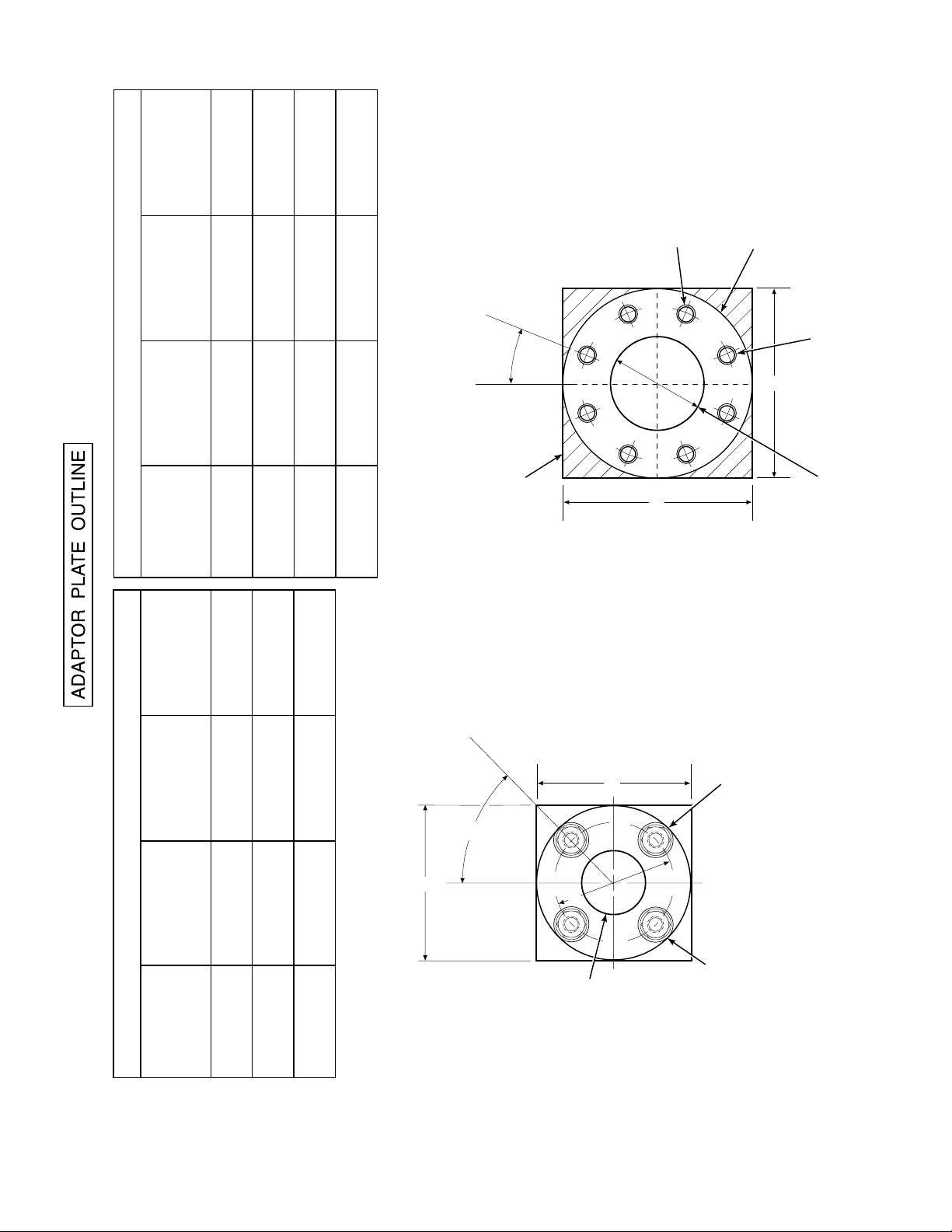
16860021
TABLE VI. ADAPTOR PLATE DIMENSIONS FOR ABRASIVE SHIELD
JIS
9.25
(P/N 3535B58G04)
DIN
9.25
(P/N 3535B58G06)
ANSI
9.00
(P/N 3535B58G02)
IN.
(mm)
"A"
DIMENSIONS
(235)
(235)
(229)
4.92
(125)
3.94
(100)
4.75
(121)
"B"
DIA
(M-20 x 2.5)
(M-16 x 2)
0.625-11
"C"
THREAD
(200)
7.894
7.48
(190)
7.50
(191)
"D"
DIA
ATTACHING HARDWARE.
NOTE: PART NUMBERS FOR ADAPTOR PLATES INCLUDE
8 THREADED HOLES
EQUALLY SPACED ON
D DIA B.C.
o
ABRASIVE SHIELD
FLANGE O.D.
C
22.5
A
B
A
CROSSHATCHED AREA IN 4
OUTSIDE WALL SURFACE.
CORNERS MAY BE USED TO
FIELD BOLTING OF PLATE TO
TABLE V. ADAPTOR PLATE DIMENSIONS FOR PROBE
JIS
6.50
(P/N 4512C35G01)
DIN
7.5
(P/N 4512C36G01)
ANSI
6.00
(P/N 4512C34G01)
IN.
(mm)
"A"
DIMENSIONS
(165)
(191)
(153)
(M-12 x 1.75)
(M-16 x 2)
0.625-11
"B"
THREAD
(130)
5.118
(145)
5.708
4.75
(121)
"C"
DIA
ATTACHING HARDWARE.
NOTE: PART NUMBERS FOR ADAPTOR PLATES INCLUDE
PROVIDE ADDITIONAL HOLES FOR
AND 12 FT ABRASIVE SHIELD
ADAPTOR PLATE FOR 3, 6, 9,
INSTALLATIONS. SEE SHEET 2.
4 STUDS,
LOCKWASHERS AND
NUTS EQUALLY
SPACED ON
A
o
C DIA B.C.
45
A
C
B
2.500 DIA
ADAPTOR PLATE FOR
STD WORLD CLASS 3000
PROBE INSTALLATION.
SEE SHEET 1.
Figure 2-1. Probe Installation (Sheet 3 of 5)
IB-106-300NH
2-4

INSTALLATION FOR METAL
WALL STACK OR DUCT
CONSTRUCTION
INSTALLATION FOR MASONRY
WALL STACK CONSTRUCTION
MTG HOLES
SHOWN ROTATED
o
45 OUT OF
TRUE POSITION
WELD OR BOLT ADAPTOR
PLATE TO METAL WALL
OF STACK OR DUCT.
JOINT MUST BE AIR TIGHT.
0.50 [13]
3.75 [95]
MIN DIA HOLE
IN WALL
STACK OR DUCT
METAL WALL
0.50 [13]
BOLT ADAPTOR
PLATE TO OUTSIDE
WALL SURFACE
FIELD WELD
PIPE TO
ADAPTOR PLATE
MTG HOLES
SHOWN ROTATED
o
45 OUT OF
TRUE POSITION
JOINT MUST
BE AIRTIGHT
OUTSIDE WALL
SURFACE
NOTE: ALL MASONRY STACK WORK AND JOINTS EXCEPT
ADAPTOR PLATE NOT FURNISHED BY ROSEMOUNT.
4.50 [114]
O.D. REF
PIPE 4.00 SCHED 40
PIPE SLEEVE (NOT
BY ROSEMOUNT)
LENGTH BY CUSTOMER
MASONRY
STACK WALL
WELD OR BOLT ADAPTOR
PLATE TO METAL WALL
OF STACK OR DUCT.
JOINT MUST BE AIR TIGHT.
2.50 [63.5]
MIN DIA HOLE
IN WALL
STACK OR DUCT
METAL WALL
Figure 2-1. Probe Installation (Sheet 4 of 5)
BOLT ADAPTOR
PLATE TO OUTSIDE
WALL SURFACE
JOINT MUST
BE AIRTIGHT
OUTSIDE WALL
SURFACE
NOTE: DIMENSIONS IN INCHES WITH
MILLIMETERS IN PARENTHESES.
IB-106-300NH
2-5
FIELD WELD
PIPE TO
ADAPTOR PLATE
3.50 [89]
O.D. REF
PIPE 3.00 SCHED 40
PIPE SLEEVE (NOT
BY ROSEMOUNT)
LENGTH BY CUSTOMER
MASONRY
STACK WALL
624038

o
60 MAX.
BRACE BARS
(NOT BY ROSEMOUNT)
2.00
(51)
1.00
(25)
NOTE: DIMENSIONS IN INCHES WITH
MILLIMETERS IN PARETHESES.
VERTICAL BRACE CLAMP ASSY.
HORIZONTAL BRACE CLAMP ASSY.
(BOTH BRACE CLAMP ASSEMBLIES ARE THE SAME.
INSTALLATION AND LOCATION OF CLAMP ASSEMBLIES
AND BRACE BARS TO BE DONE IN FIELD.)
BY ROSEMOUNT
}
o
30 MIN.
4.12
(105)
4.12
(105)
2 HOLES - 0.625
(16) DIA. FOR
0.50 (12) DIA.
BOLT
0.375
(10)
1.00
(25) MAX.
NOTE: BRACING IS FOR VERTICAL AND HORIZONTAL PROBE INSTALLATION.
EXTERNAL BRACING REQUIRED FOR 9 FT AND 12 FT
(2.75 M AND 3.66 M) PROBES AS SHOWN ABOVE.
5.62
(143)
5.62
(143)
36.00 (914)
ABRASIVE SHIELD
Figure 2-1. Probe Installation (Sheet 5 of 5)
27270008
If using the optional ceramic diffusor
4.
element, the vee deflector must be correctly
oriented. Before inserting the probe, check
the direction of flow of the gas in the duct.
Orient the vee deflector on the probe so that
the apex points upstream toward the flow
(Figure 2-2). This may be done by
loosening the setscrews, and rotating the
vee deflector to the desired position.
Retighten the setscrews.
In horizontal installations, the probe
5.
junction box should be oriented so that the
system cable drops vertically from the
probe junction box. In a vertical
installation, the system cable can be
oriented in any direction.
If the system has an abrasive shield, check
6.
the dust seal packings. The joints in the two
packings must be staggered 180°. Also,
make sure that the packings are in the hub
IB-106-300NH
2-6
grooves as the probe slides into the 15°
forcing cone in the abrasive shield.
NOTE
If process temperatures will exceed 392°F
(200°C), use anti-seize compound on stud
threads to ease future removal of probe.
Insert probe through the opening in the
7.
mounting flange and bolt the unit to the
flange. When probe lengths selected are 9
or 12 ft (2.75 or 3.66 m), special brackets
are supplied to provide additional support
for the probe inside the flue or stack. See
Figure 2-1, sheet 5.
NOTE
Probe Installation
To maintain CE compliance, ensure there is
a good connection between the chassis of
the probe and earth.
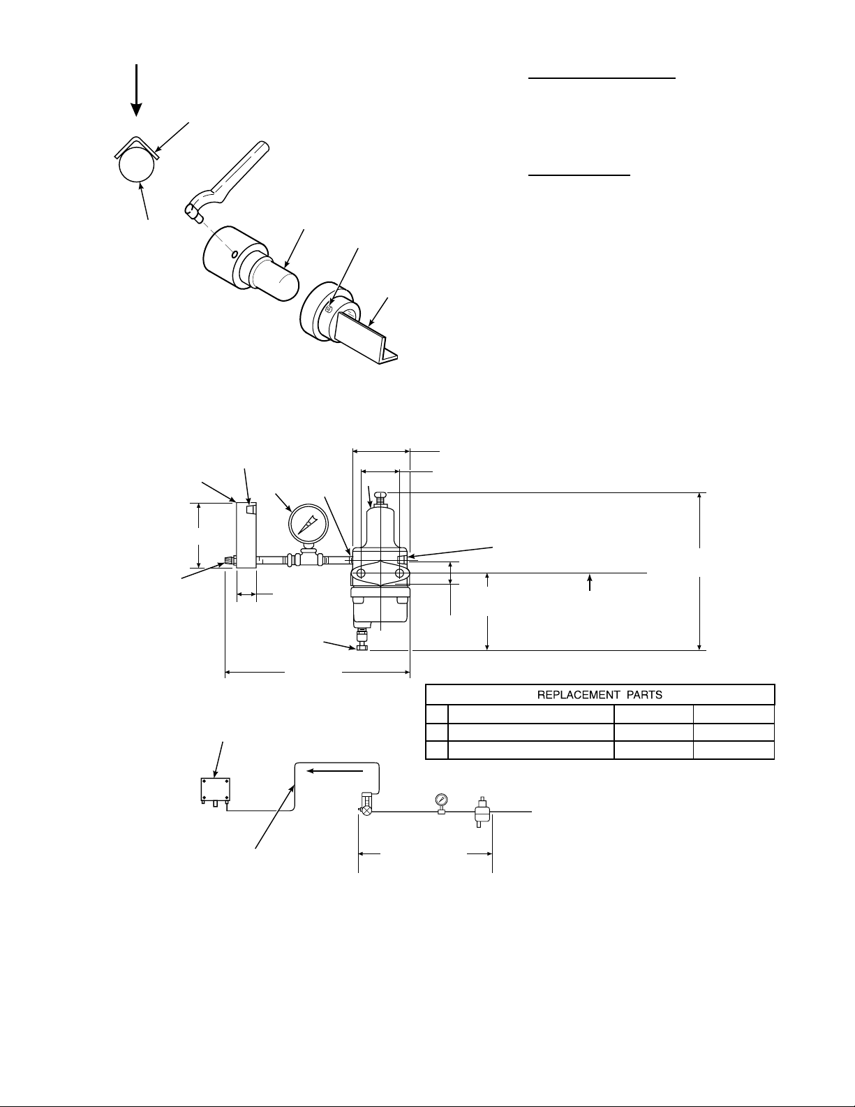
APEX
FILTER
GAS FLOW
DIRECTION
VEE
DEFLECTOR
DIFFUSION
ELEMENT
SETSCREW
DEFLECTOR
VEE
624017
c. Reference Air Package. After the oxygen
analyzing (probe) unit is installed, connect the
reference air set to the probe junction box. T he
reference air set should be installed in
accordance with Figure 2-3.
d. Service Required.
Power input: 100, 115 or 220 Vac single
1.
phase, 50 to 60 Hz, 3 amp minimum. (See
label.)
Compressed air: 10 psig (68.95 kPa)
2.
minimum, 225 psig (1551.38 kPa)
maximum at 2 sc fh (56.6 L/hr) maxi mum;
supplied by one of the following (less than
40 parts-per-million total hydrocarbons).
Regulator outlet pressure should be set at 5
psi (35 kPa).
Figure 2-2. Orienting the Optional Vee Deflector
0.125-27 NPT FEMALE
OUTLET CONNECTION
1
4.81 (122.17)
FLOW SET
POINT KNOB
0.250 OR 6 MM OD
TUBE COMPRESSION
FITTING (SUPPLIED BY WECO)
2
OUTLET
1.19
(30.22)
DRAIN VALVE
10.0 REF
(254)
TO PROBE HEAD
3
(a) Instrument air - clean, dry.
3.12 (79.25) MAX
2.250 (57.15)
0.25-18 NPT FEMALE
INLET CONNECTION
2.0
(50.80)
1.50
(38.10)
1 FLOWMETER 0.2-2.0 SCFH 771B635H02
2 2" PRESSURE GAGE 0-15 PSIG 275431-006
3 COMBINATION FILTER-REG. 0-30 PSIG 4505C21G01
NOTE: DIMENSIONS ARE IN INCHES WITH
2 MOUNTING HOLES
3.19 (81.03) LG
THROUGH BODY FOR
0.312 (7.92) DIA BOLTS
MILLIMETERS IN PARENTHESES.
8.50 MAX
(215.90)
COMPRESSED AIR SUPPLY
10-225 PSIG MAX PRESSURE
0.250 OR 6 MM OD TUBING
(SUPPLIED BY CUSTOMER)
SCHEMATIC HOOKUP FOR REFERENCE AIR SUPPLY ON OXYGEN ANALYZER PROBE HEAD.
REF AIR SET
263C152G01
Figure 2-3. Air Set, Plant Air Connection
IB-106-300NH
2-7
27270003
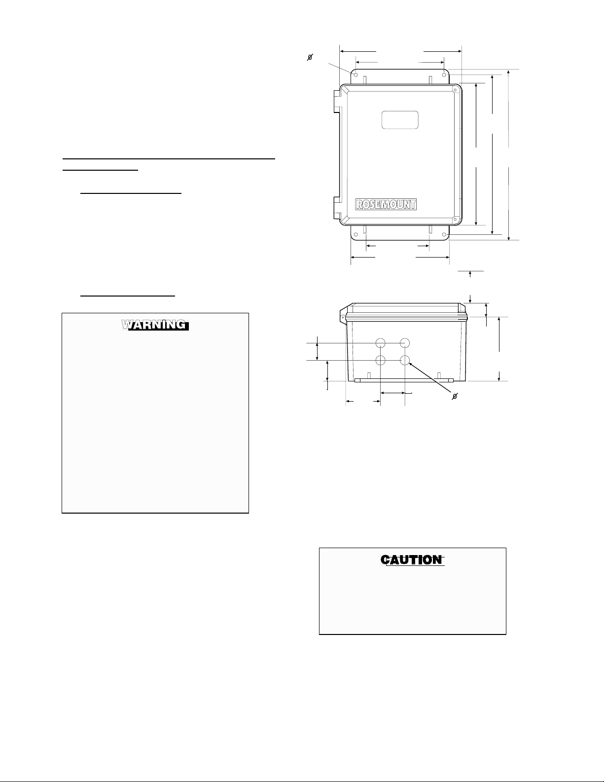
(b) Bottled standard air with step-down
regulator.
(c) Bottled compressed gas mixture
(20.95% oxygen in nitrogen).
0.31
.
11.24 25.5
.00 203.2
(d) Other equivalent clean, dry, oil-free
air supply.
2-2. INTELLIGEN T FIELD TR ANSM ITTER ( IFT)
INSTALLATION
a. Mechanical Installation. The outline drawing
of the IFT module in Figure 2-4 shows mounting
centers and clearances. The NEMA 4X enclosure
is designed to be mounted on a wall or bulkhead.
The IFT should be installed no more than 1200
feet (364 m) from the optional HPS or 150 feet
(45 m) from the probe if HPS is not installed in
the system.
b. Electrical Connections.
To meet the Safety Requirements of IEC
1010 (EC requirement), and ensure safe
operation of this equipment, connection
to the main electrical power supply must
be made through a circuit breaker (min
10A) which will disconnect all current
carrying conductors during a fault
situation. This circuit breaker should
also include a mechanically operated
isolating switch. If not, then another
external means of disconnecting the
supply from the equipment should be
located close by. Circuit breakers or
switches must comply with a recognized
standard such as IEC 947.
NOTE
Refer to Figure 2-7 for fuse locations and
specifications.
15.00
31.0
5. 14.3
.00 22.
1.2
41.1
2.00
50.
NOTE
3.3
5.3
DESIGN DIMENSIONS ARE IN INCHES
WITH MILLIMETERS IN PARENTHESES.
13.24
33.3
11.5 22.1 MINIMUM DOOR
SWING CLEARANCE
2.25
5.15
0.
22.00
1.00
40.4
1.25
31.5
.0
152.4
2110002
Figure 2-4. Outline of Intelligent Field Trans mitter
over 150 feet (45 m). The electrical
connections for a non-HPS equipped
system should be made as described in the
electrical installation diagram, Figure 2-8.
Refer to Figure 2-14 for connections for an
HPS equipped system.
The IFT can be configured for 100, 120,
1.
220, or 240 line voltages. For 120 Vac
usage, install JM8, JM7, and JM1 on the
power supply board. For 220 Vac usage,
install jumpers JM6, JM5, JM2 (refer to
Figure 2-5 and Figure 2-7).
For installations where the cable run is le ss
2.
than 150 feet (45 m), the IFT can be
configured to connect directly to a probe.
An optional HPS is available for cable runs
IB-106-300NH
2-8
Do not install jumper JM6 on the
microprocessor board, or JM1 on the
interconnect board, if an HPS is
installed in the system. This will result
in system failure.
The IFT must have JM6 on the micro-
3.
processor board (Figure 2-9 and Figure
2-10) and JM1 on the interconnect board
(Figure 2-11 and Figure 2-12) installed if
an HPS is not installed in the system.
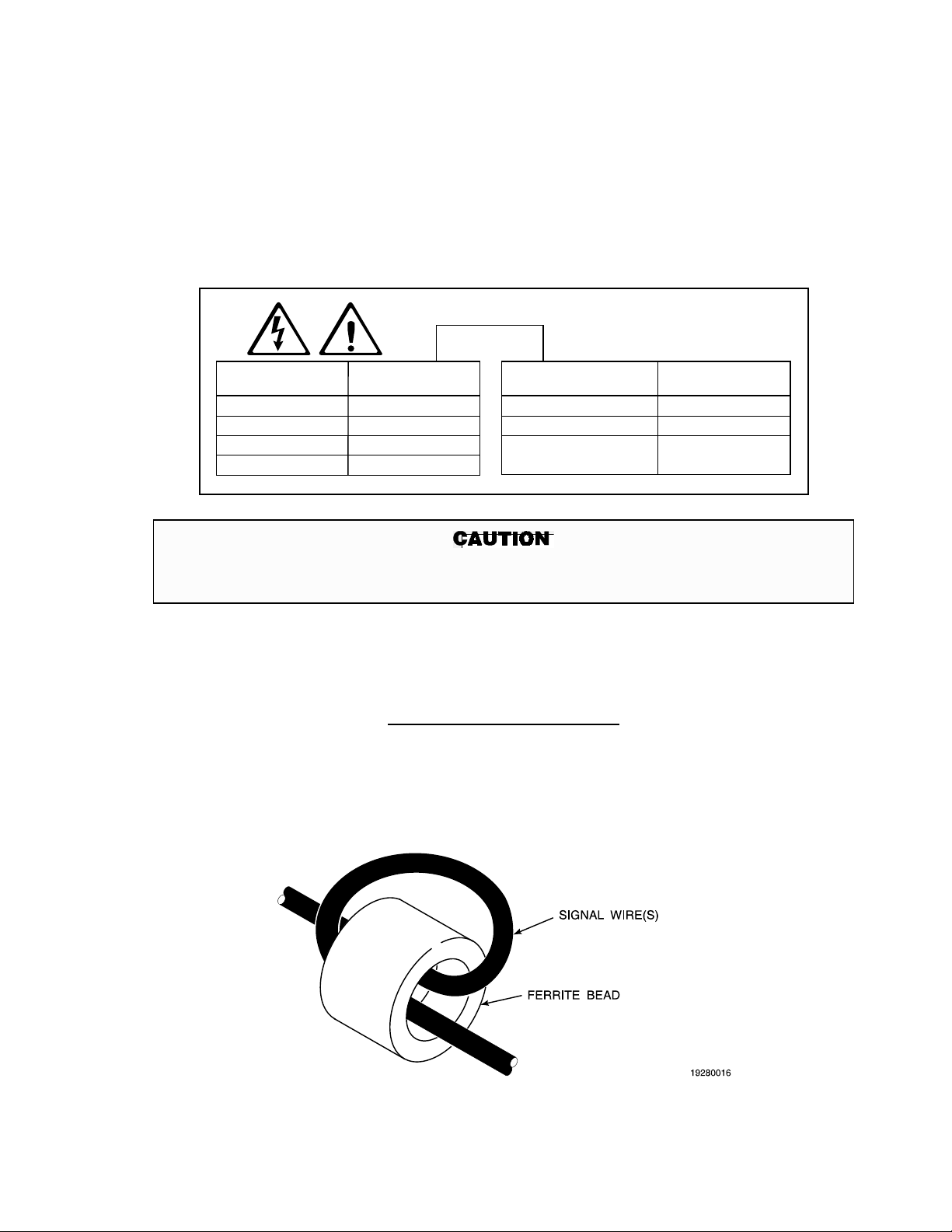
If an MPS is not used in the system, wire
4.
jumper between CAL RET and NO GAS
must be installed on the interconnect board.
Remove wire jumper if MPS is installed in
the system. Refer to Figure 2-8, note 6.
The power cable should comply with the
5.
safety regulations in the user's country and
should not be smaller than 16 gauge, 3 amp.
LINE VOLTAGE
SELECTION
100 V.A.C.
120 V.A.C.
220 V.A.C.
240 V.A.C.
JUMPER
(INSTALL)
JM3, JM7, JM2
JM8, JM7, JM1
JM6, JM5, JM2
JM6, JM5, JM1
JUMPER
CONFIGURATION
WORLD CLASS PROBE (44V)
REPLACEMENT" PROBE (115V)
Before supplying power to the IFT, verify
6.
that the jumpers have been properly set
in the IFT (Figure 2-5, Figure 2-9, and
Figure 2-11).
Terminal strip J5 on the power supply
7.
board is used for supplying the IFT with
power. Terminal strip J6 on the power
supply board is used to supply the probe
heater with power if an HPS is not used
(Figure 2-7).
ALWAYS DISCONNECT LINE VOLTAGE
FROM INTELLIGENT FIELD TRANSMITTER
BEFORE CHANGING JUMPERS.
PROBE HEATER
VOLTAGE SELECTION
218 PROBE (115V)
WORLD CLASS "DIRECT
JUMPER
(INSTALL)
JM10
JM9
JM9
2110012
If incorrect heater voltage is selected, damage to the probe may occur. For HPS voltage selection
jumper, refer to Figure 2-15. Always update the relevant labeling to reflect the set vo lt age.
Figure 2-5. Power Supply Board Jumper Configuratio n
NOTE
General Wiring Recommendations
To maintain CE compliance and ensure proper EMC performance, all signal wires to the Interconnect
Board, with the exception of the probe cable, should be looped through the ferrite beads provided as
shown in Figure 2-6 (P/N 1L04253H01). Signal wires may be grouped together and looped through
before exiting the enclosure. Ferrite beads should be placed as close as possible to the exit point. Ferrite
beads are provided for European Common Market applications only.
Figure 2-6. Signal Wire Routing
IB-106-300NH
2-9

FUSES
FUSES
NOTE: ALL FUSES (F1 THROUGH F5)
ARE 5A @ 250 VAC, ANTISURGE, CASE SIZE5X20MM,
TYPE T TO IEC127, SCHURTER.
Figure 2-7. IFT Power Supply Boa r d Jumpers
IB-106-300NH
2-10
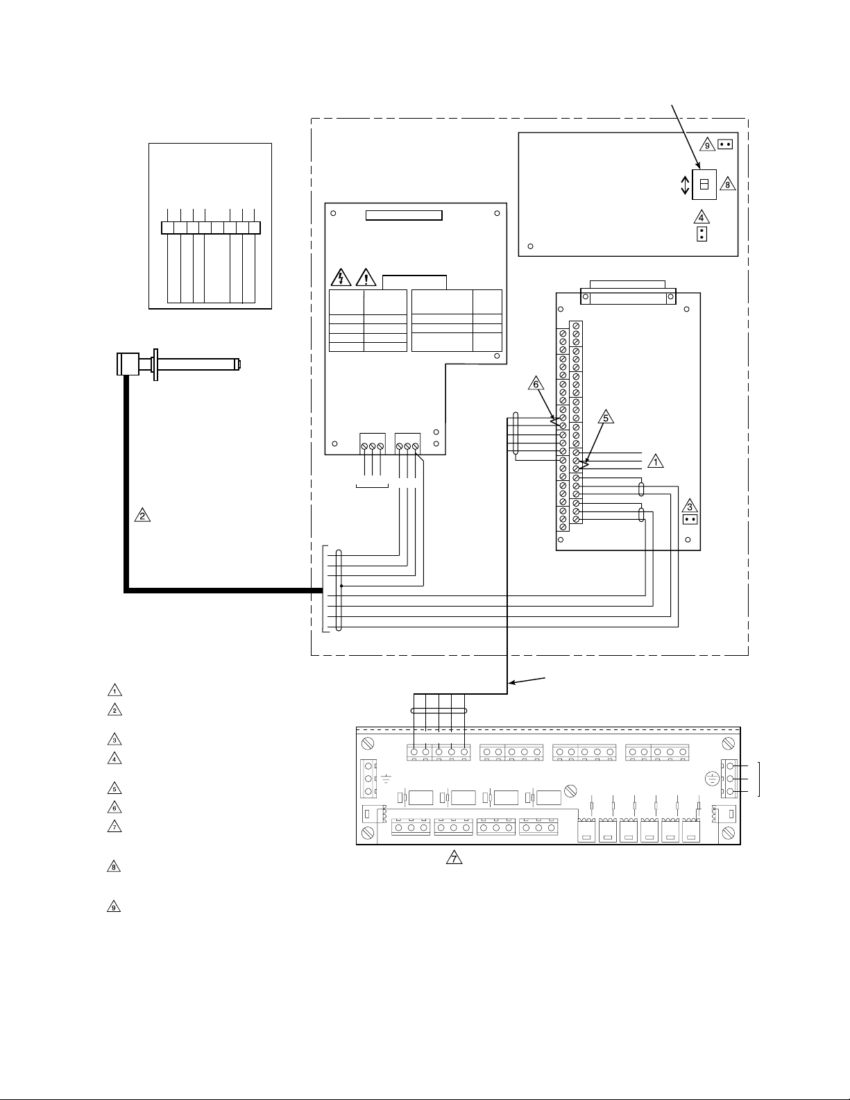
PROBE JUNCTION
BOX WIRING
GN CELL -VE
OR CELL +VE
YE CHROMEL
RD ALUMEL
GN
BK
123456 78
BL
YE
RD
OR
GN
WH
E
R
HEATER
CURRENT/VOLTAGE
SELECTOR SWITCH
3D39513G
MICROPROCESSOR
BOARD
}
BK
J1
BK
H
3D39122G REV
POWER SUPPLYBOARD
ALWAYS DISCONNECT LINE VOLTAGE
FROM INTELLIGENT FIELD TRANSMITTER
BEFORE CHANGING JUMPERS.
JM7
I
V
JM6
PROBE MV -
PROBE MV +
PROBE TC +
PROBE TC -
WORLD CLASS
PROBE
NOTES:
STACK TC WIRING AS REQUIRED.
SPECIAL PROBE CABLE BETWEEN PROBE
AND IFT BY ROSEMOUNT.
INSTALL JM1 ON INTERCONNECT BOARD.
INSTALL JM6 ON MICROPROCESSOR
BOARD.
IF STACK TEMPERATURE NOT USED.
IF MPS 3000 NOT USED.
1 RELAY PER PROBE AVAILABLE FOR
CALIBRATION STATUS INDICATION. (48 V
max, 100 mA max)
CURRENT/VOLTAGE SELECTOR SWITCH
MUST BE SELECTED TO CURRENT (I) FOR
HART COMMUNICATIONS APPLICATIONS.
JUMPER JM7 INFORMATION APPEARS IN
FIGURE 2-9.
LINE
VOLTAGE
SECTION
100 V.A.C.
120 V.A.C.
220 V.A.C.
240 V.A.C.
JUMPER CONFIGURATION
JUMPER
(INSTALL)
JM3, JM7, JM2
JM8, JM7, JM1
JM6, JM5, JM2
JM6, JM5, JM1
PROBE HEATER
VOLTAGE SECTION
WORLD CLASS PROBE
218 PROBE
WORLD CLASS "DIRECT
REPLACEMENT" PROBE
JUMPER
(INSTALL)
JM10
JM9
JM9
J2
3D39120G REV
INTERCONNECT BOARD
J3
J1
J4
J5
CAL RET
J5 J6
L
H
EN
LINE
VOLTAGE
BK
WH
GN
PU
OR
BL
YE
RD
INTELLIGENT FIELD
TRANSMITTER IFT 3000
ER
PROBE 1
LINE OUT LINE IN
J10
L
N
HI GAS
IN CAL
CAL RET
NO GAS
LOW GAS
NO GAS
LO GAS
HI GAS
IN GAS
SHIELD
PROBE 2 PROBE 3 PROBE 4
IN CAL
HI GAS
NO GAS
CAL RET
LOW GAS
NC C NO NC C NO NC C NO NC C NO
J11
PROBE 1
PROBE 2 PROBE 3 PROBE 4
MPS 3000 MULTIPROBE CALIBRATION GAS SEQUENCER (OPTIONAL)
MPS TERMINATION BOARD
J6
J7
SHIELD
STACK TC STACK TC +
J8
SHIELD
PROBE TC -
RD
YE
PROBE TC +
J9
SHIELD
BL
OR
5 CONDUCTOR SHIELDED CABLE
PER PROBE #16 AWG BY CUSTOMER
IN CAL
HI GAS
CAL RET
PROBE 1
SOLENOID
J13 J14 J15 J16 J17 J18
PROBE MV
PROBE
NO GAS
LOW GAS
PROBE 2
SOLENOID
-
MV+
HI GAS
PROBE 3
SOLENOID
IN CAL
PROBE 4
SOLENOID
NO GAS
CAL RET
HIGH GAS
SOLENOID
JM1
L
L
LOW GAS
N
LOW GAS
SOLENOID
SWITCH
PRESSURE
J12
E
N
LINE
VOLTAGE
27270011
Figure 2-8. Wiring Layout for IFT Systems without HPS
IB-106-300NH
2-11

OUTPUT JUMPER
HPS Remove JM6
Probe (No HPS) Install JM6
ANALOG OUTPUT
(Condition during
microcontroller failure) JUMPER
Output = zero Install JM7
Output = maximum Remove JM7
analog output is typically sent to recording
equipment such as chart recorders. Relay
outputs are typically sent to annunciators.
Relays K1 and K2 are user configurable
3.
from the probe SETUP sub-menu (Table
5-5). Typically these are used to indicate O
values above or below specified tolerances.
OK relay is energized when unit is
functioning properly.
All wiring must conform to local and
4.
national codes.
2
(See Figure 2-10 for jumper locations.)
Figure 2-9. Microprocessor Board Jumper
Configuration
c. Analog Output and Relay Output
Connections.
The microprocessor board has a selector for
1.
voltage or current operations. Figure 2-10
shows switch orientation. In volta ge mode,
output is 0-10 V. In the current mode, the
output can be configured from the SETUP
menu to be 0-20 mA or 4-20 mA.
The analog output and relay outputs are
2.
programmed by the user as needed. The
Connect the analog output and relay outputs
5.
as shown in Figure 2-12.
2-3. HEATER POWER SUPPLY INSTALLATION
a. Mechanical Installation. The outline drawing
of the heater power supply enclosure in Figure
2-13 shows mounting centers and clearances.
The NEMA 4X enclosure is designed to be
mounted on a wall or bulkhead. The heater
power supply should be installed no further than
150 feet (45 m) from the probe. The heater
power supply must be located in a location free
from significant ambient temperature changes
and electrical noise. Ambient temperature must
be between -20° and 140°F (-30° and 60°C).
IB-106-300NH
2-12
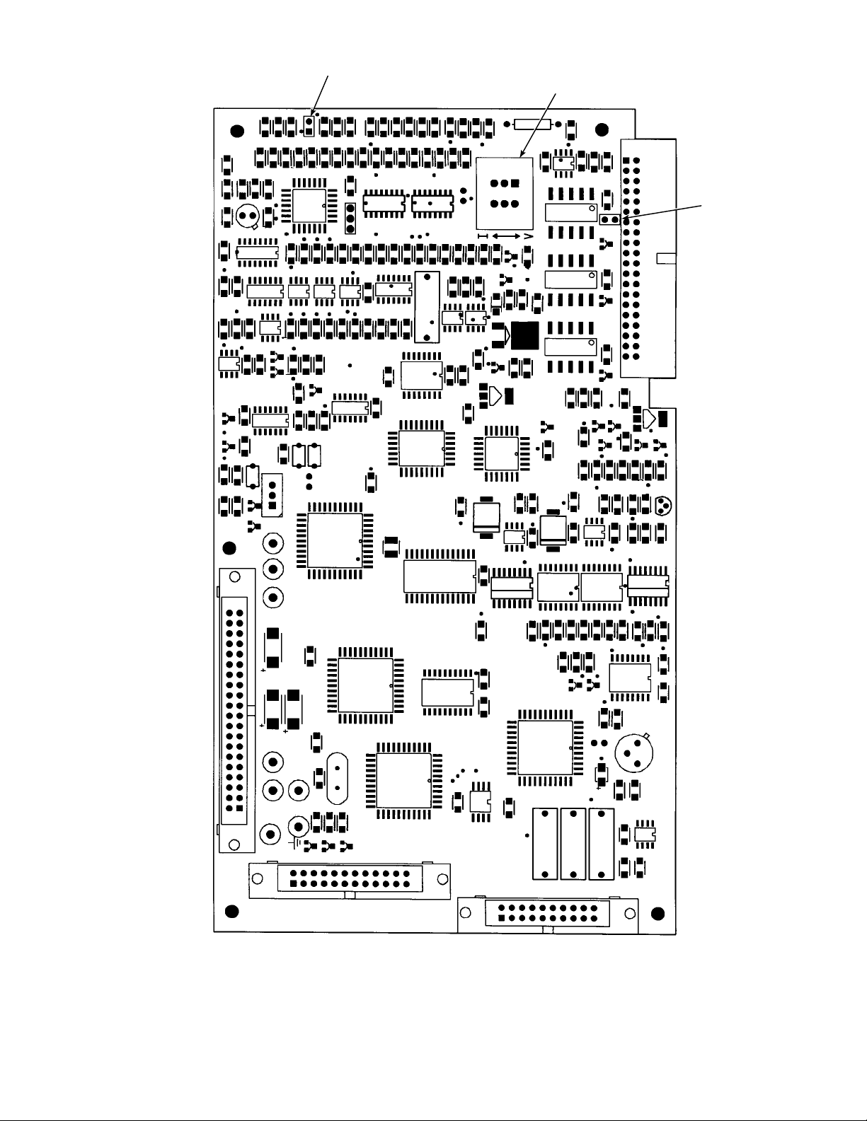
M
CURRENTV OL TAGE
SELECTOR SWITCH
JM7
SW1
J4
JM6
TO I/O
BOARD
M
TO POWER
SUPPLY CARD
TP5 TP6
TP4
+30VISO-C GNDC +5VISO-C
TP3
-15V
TP8
+5V
TP2
TP7
+15V
TP1
-5V
J1
J2
3D39513G REV
TO LDP CARD
J3
TO GUI CARD
250004
Figure 2-10. IFT Microprocessor Board
IB-106-300NH
2-13

NOTES
DENOTES SHIELD CONNECTION.
O RELA IS ENERGIED WHEN
UNIT IS FUNCTIONING PROPERL .
OUTPUT JUMPER
HPS Remove JM1
Probe (No HPS) Install JM1
Figure 2-11. Interconnect Board Jumper Configuration
24
24
23
ONC
1NC
2NC
CALINIT2
CAL INIT1
CALRET
NOGAS
LOGAS
HIGAS
INCAL
23
22
21
20
1
1
1
1
15
14
13
12
11
10
22
21
20
1
1
1
1
15
14
13
12
11
10
OCOM
ONO
1COM
1NO
2COM
2NO
ANOUT
ANOUT
RELA
RELA
5
AD50
AD50
TRIAC
TRIAC
5
4
4
3
3
2
2
1
1
Figure 2-12. IFT Interconnect Board Output Connections
STAC TC
STAC TC
PROBE TC
PROBE TC
PROBE MV
PROBE MV
M1
UNDER
SHIELD
10010
IB-106-300NH
2-14

3.25
2.
NOTE DIMENSIONS IN INCHES
WITH MILLIMETERS IN P ARENTHESES
.00
1.
3.3
2.2
10.3
24
NEMA X
NONHAARDOUS
0.31
.
6.00
4.00
101.
.50
215.
(152.4)
4.88
(124)
6.75
(171.5)
0.31
b. Electrical Connections.
Electrical connections should be made as
1.
described in the electrical installation
diagram, Figure 2-14. The wiring terminals
are divided into two layers; the bottom
(FROM PROBE) terminals should be
connected first, the top (FROM
ELECTRONICS) terminals should be
connected last (Figure 2-15). Each terminal
strip has a protective cover which must be
removed when making connections. To
remove the terminal covers, remove two
slotted screws holding cover in place.
Always reinstall terminal covers after
making connections. All wiring must
conform to local and national codes.
0.13 3.3 TH U . L. APPROVED
GASET
4.3
1.1
4
11.00
2.4
.00
203.2
1032 UNF 2A
THREADED INSERT
0.31 0.31 FR OM CORNER OF PLATE
111.3
Figure 2-13. Outline of Heater Power Supply
.
253
0.3
.
1.00 25.4 MINIMUM CLEARANCE
4.2
120
CLASS 1 DIVISION 1 GR OUP B ENCLOSURE
FOR REMOVING COVER
Power Input: 120, 220 or 240 Vac. For 120
2.
9.17
(233)
Vac usage, install jumpers JM4 and JM1.
For 220 or 240 Vac usage, install jumper
JM5 (see label, Figure 2-16).
NOTE
For 100 Vac usage, the heater power supply
is factory-supplied with a different transformer. When using the HPS with 100 Vac
transformer, install jumpers JM1 and JM4.
The power cable should comply with safety
3.
regulations in the user's country and should
not be smaller than 16 gauge, 3 amp.
.50
215.
0.5 14
DIA 2
MOUNTING
HOLES
.1
15.
686029
NOTE
Refer to Figure 2-17 for fuse locations and
specifications.
IB-106-300NH
2-15

PROBE JUNCTION
BOX WIRING
HEATER
GN CELL -VE
OR CELL +VE
YE CHROMEL
RD ALUMEL
123456 78
BL
YE
RD
OR
PROBE MV -
PROBE MV +
PROBE TC +
PROBE TC -
}
GN
BK
BK
BK
GN
WH
E
H
R
WORLD CLASS PROBE
LINE VOLTAGE
SELECTION
120 V.A.C./100 V.A.C.
11
220/240 V.A.C.
PROBE HEATER
VOLTAGE SECTION
WORLD CLA SS PROBE JM7
JUMPER
(INSTALL)
JM4, JM1
JM5
JUMPER
(INSTALL)
NOTES
1
2
3
4
5
6
7
8
9
10
11
JUMPER
CONFIGURATION
(NEXT GENERATION)
RELAY WIRE IS OPTIONAL, RELAY CAN BE BYPASSED
WITH JUMPER JM-2 IF NOT WIRED TO THE IFT.
STACK TC WIRING AS REQUIRED.
ALL WIRES #16-#22 AWG TWISTED PAIR WITH SHIELD
BY CUSTOMER EXCEPT AS NOTED.
STANDARD PROBE CABLE BETWEEN PROBE AND
HPS BY ROSEMOUNT.
REMOVE JM1 ON INTERCONNECT BOARD.
REMOVE JM6 ON MICROPROCESSOR BOARD.
IF RELAY WIRE OF NOTE 1 INSTALLED THEN
REMOVE
JM2 ON HPS 3000.
IF STACK TEMPERATURE NOT USED.
IF MPS 3000 NOT USED.
1 RELAY PER PROBE AVAILABLE FOR CALIBRATION
STATUS INDICATION (48 V max, 100 mA max).
100 V.A.C. REQUIRES TRANSFORMER PART
NUMBER 1M02961G02.
JUMPER JM7 INFORMATION APPEARS IN FIGURE 2-9.
ALWAYS DISCONNECT LINE VOLTAGE
FROM HEATER POWER SUPPLY
BEFORE CHANGING JUMPERS.
HEATER
POWER
REMOTE
ON
ELECTRONICS
SELECTION
REMOVE JM2
INSTALL JM2
JUMPER
REMOVE JM3, JM6DIGITAL
ON
7
1
4
OR CELL+
BL CELL -
YE HTR TC +
RD HTR TC -
WH
BK
GN
GN/YE
TOP
TRIAC RELAY
J9
+
+++
-
PROBE
PROBE
MV
J8
+
-
BOTTOM
PROBE
MV
J3
+
-
STACK
2
TC
J2 J1
+
-
2
1
STACKTCANALOG
---
AD590
TC
+
-
PROBE
TC
+
-
PROBE
HEATER
RH
HEATER
BK
(INTERNAL
WIRING)
HPS 3000 INTERFACE MODULE
WH
WHBK
LINE
N
L
2 TWISTED PAIR SHIELDED
#22 AWG BY CUSTOMER
(OPTIONAL)
4 TWISTED PAIR SHIELDED
#22 AWG BY CUSTOMER
LINE
VOLTAGE
A
B
Figure 2-14. Wiring Layout for Complete IFT 3000 System with HPS (Sheet 1 of 2)
IB-106-300NH
2-16
22540001

CURRENT/VOLTAGE
SELECTOR SWITCH
LINE
VOLTAGE
SECTION
100 V.A.C.
120 V.A.C.
200 V.A.C.
220 V.A.C.
240 V.A.C.
JUMPER
(INSTALL)
JM3, JM7, JM2
JM8, JM7, JM1
JM4, JM5, JM2
JM6, JM5, JM2
JM6, JM5, JM1
J5 J6
L
LINE
VOLTAGE
J1
ALWAYS DISCONNECT LINE VOLTAGE
FROM INTELLIGENT FIELD TRANSMITTER
BEFORE CHANGING JUMPERS.
JUMPER CONFIGURATION
PROBE HEATER
VOLTAGE SECTION
NOT USED REMOVE
NOT USED
EN
3D39122G REV
POWER SUPPLYBOARD
JUMPER
(INSTALL)
JM9, JM10
3D39513G
MICROPROCESSOR
BOARD
CAL RET
NO GAS
LO GAS
HI GAS
IN CAL
SHIELD
RELAY –
RELAY +
SHIELD
AD590 –
AD590 +
SHIELD
TRIAC –
TRIAC +
J2
J3
J4
J5
J6
J7
SHIELD
STACK TC –
STACK TC +
J8
SHIELD
PROBE TC –
PROBE TC +
J9
SHIELD
PROBE MV –
PROBE MV +
J1
3D39120G REV
INTERCONNECT BOARD
JM7
I
V
JM6
JM1
A
B
INTELLIGENT FIELD
TRANSMITTER IFT 3000
PROBE 1
LINE OUT LINE IN
L
IN CAL
HI GAS
NO GAS
CAL RET
J10
N
NC C NO NC C NO NC C NO NC C NO
J11
PROBE 1
PROBE 2 PROBE 3 PROBE 4
MPS 3000 MULTIPROBE CALIBRATION GAS SEQUENCER (OPTIONAL)
PROBE 2 PROBE 3 PROBE 4
IN CAL
HI GAS
LOW GAS
CAL RET
MPS TERMINATION BOARD
5 CONDUCTOR SHIELDED CABLE
PER PROBE #16 AWG BY CUSTOMER
NO GAS
IN CAL
HI GAS
NO GAS
LOW GAS
CAL RET
PROBE 1
SOLENOID
J13 J14 J15 J16 J17 J18
PROBE 2
LOW GAS
SOLENOID
PROBE 3
SOLENOID
HI GAS
IN CAL
PROBE 4
SOLENOID
NO GAS
CAL RET
LOW GAS
LOW GAS
HIGH GAS
SOLENOID
L
N
SOLENOID
SWITCH
PRESSURE
J12
Figure 2-14. Wiring Layout for Complete IFT 3000 System with HPS (Sheet 2 of 2)
L
LINE
E
VOLTAGE
N
27270012
IB-106-300NH
2-17

SCREW
2 PER CO VER
TERMINAL
COVERS
TRANSFORMER
FRONT
TERMINAL STRIP
FR OM ELECTRONICS
TRANSFORMER
SIDE
Figure 2-15. Heater Power Supply Wiring Connections
TERMINAL STRIP
FR OM ELECTRONICS
250005
IB-106-300NH
2-18

1
2
NOTES
1
100 V.A.C. OPERATION REUIRES TRANSFORMER PART
NUMBER 1M021G02.
2
REFER TO TABLE 35 FOR PROPER SET POINT SELECTION.
0310122
Figure 2-16. Jumper Selection Label
NOTE
Before supplying power to the hea ter pow er
supply, verify that jumpers JM3, JM6 are
removed and JM7 is installed. If relay wire
(Figure 2-14, note 1) is installed, JM 2 must
be removed from HPS Mother Board
(Figure 2-17).
Before supplying power to the heater power
4.
supply, verify that the jumpers on the
mother board, Figure 2-17, are properly
configured. Jumpers JM3 and JM6 should
be removed and JM7 should be installed.
Additionally, make sure that the proper
jumper for your line voltage is installed,
Figure 2-16. If relay wire (Figure 2-14, note
1) is not installed, JM 2 should be installed
on the HPS Mother Board (Figure 2-17).
NOTE
Refer to Figure 2-9 and Figure 2-11 for
proper IFT jumper configuration. IFT
microprocessor and interconnect board
jumper configurations must be set correctly
in order for HPS to work properly.
JM1
JM2
JM4
JM7
FUSES
3D3 080G REV
FUSE
NOTE: ALL FUSES ARE 5A @ 250 VAC,
ANTI-SURGE, CASE SIZE
5 X 20 MM, TYPE T TO IEC127,
SCHURTER.
JM5
29850001
IB-106-300NH
2-19
Figure 2-17. Jumpers on HPS Mother Board.

2-4. MULTIPROBE CALIBRATION
GAS SEQUENCER INSTALLATION
a. Mechanical Installation. The outline drawing
of the MPS module in Figure 2-18 shows
mounting centers and clearances. The box is
designed to be mounted on a wall or bulkhead.
The MPS module should be installed no further
than 300 feet (91 mz) piping distance from the
probe, and no more than 1000 feet (303 m)
cabling distance from the IFT. Install the MPS
module in a location where the ambient
temperature is between -20° and 160°F (-30° and
71°C).
12.00
(304.80)
10.00
(254.00)
b. Gas Connections. Figure 2-19 shows the
bottom of the MPS where the gas connections
are made. 1/4 inch threaded fittings are used.
Connect the reference air supply to INSTR.
1.
AIR IN. The air pressure regulator valve is
set at the factory to 20 psi (138 kPa). If the
reference air pressure should need readjustment, turn the knob on the top of the valve
until the desired pressure is obtained.
Connect the high O
2.
calibration gas to
2
HIGH GAS. The calibration gas pressure
should be set at 20 psi (138 kPa).
PROBE1 PROBE2 PROBE3 PROBE4
LOWCAL
CALGAS
HIGHCAL
GASIN
INSTR
AIR
CALGAS
GASIN
OUT
OUT
REFAIR
REFAIR
OUT
OUT
14.00 (355.60) REF
Figure 2-18. MPS Module
CALGAS
REFAIR
12.00
(304.80)
NOTE: DIMENSIONS ARE IN INCHES
WITH MILLIMETERS IN
CALGAS
OUT
OUT
REFAIR
OUT
OUT
PARENTHESES.
0.84 (21.34)
1.96 (49.78)
3.09 (78.49)
4.21 (106.93)
5.25 (133.35)
5.54 (140.72)
27270013
IB-106-300NH
2-20

Connect the low O
3.
calibration gas to LOW
2
GAS. The calibration gas pressure should
be set at 20 psi (138 kPa).
than one probe system is being used, the
additional probes and electric packages would be
wired similar to the first probe.
Connect the REF AIR OUT to the reference
4.
air fitting on the probe junction box.
Connect the CAL GAS OUT to the
5.
calibration gas fitting on the probe junction
box.
If the MPS is configured for multiple
6.
probes (up to four), repeat steps 4 and 5 for
each additional probe.
A check valve is required for each probe
connected to an MPS to prevent
condensation of flue gas in the
calibration gas lines. The check valve
must be located between the calibration
fitting and the gas line.
c. Electrical Connections. Electrical connections
should be made as described in the electrical
installation diagram, Figure 2-20. All wiring
must conform to local and national codes. The
electrical connections will exist only between the
electronics package and the MPS to enable
automatic and semiautomatic calibration. If more
NOTE
Refer to Figure 2-20 for fuse locations and
specifications.
Run the line voltage through the bulkhead
1.
fitting on the bottom of the MPS where
marked LINE IN, Figure 2-19. Connect the
line voltage as shown in Figure 2-20 to the
LINE IN terminal on the MPS termination
board located inside the unit. Tighten the
cord grips to provide strain relief.
The MPS can accommodate up to four
2.
probes. The terminal strips on the MPS
termination board are marked PROBE 1,
PROBE 2, PROBE 3, and PROBE 4. Select
PROBE 1 if this is the first probe and
electronic package installed on the MPS.
Make the connections from the MPS to the
3.
IFT as shown in Figure 2-20. Run wires
from the MPS Termination Board inside the
unit through the bulkhead fitting on the
bottom of the unit where marked SIGNAL
IN, Figure 2-19. After the connections are
made, tighten the cord grips to provide
strain relief.
DRAIN
PROBE 1 PROBE 2 PROBE 3 PROBE4
LOW CAL
CAL GAS
CAL GAS
CAL GAS
HIGH CAL
GAS IN
INSTR
AIR
GAS IN
OUT
REF AIR
OUT
OUT
REF AIR
OUT
OUT
REF AIR
OUT
CAL GAS
OUT
REF AIR
OUT
Figure 2-19. MPS Gas Connections
IB-106-300NH
2-21
LINE IN
SIGNAL IN
27270014
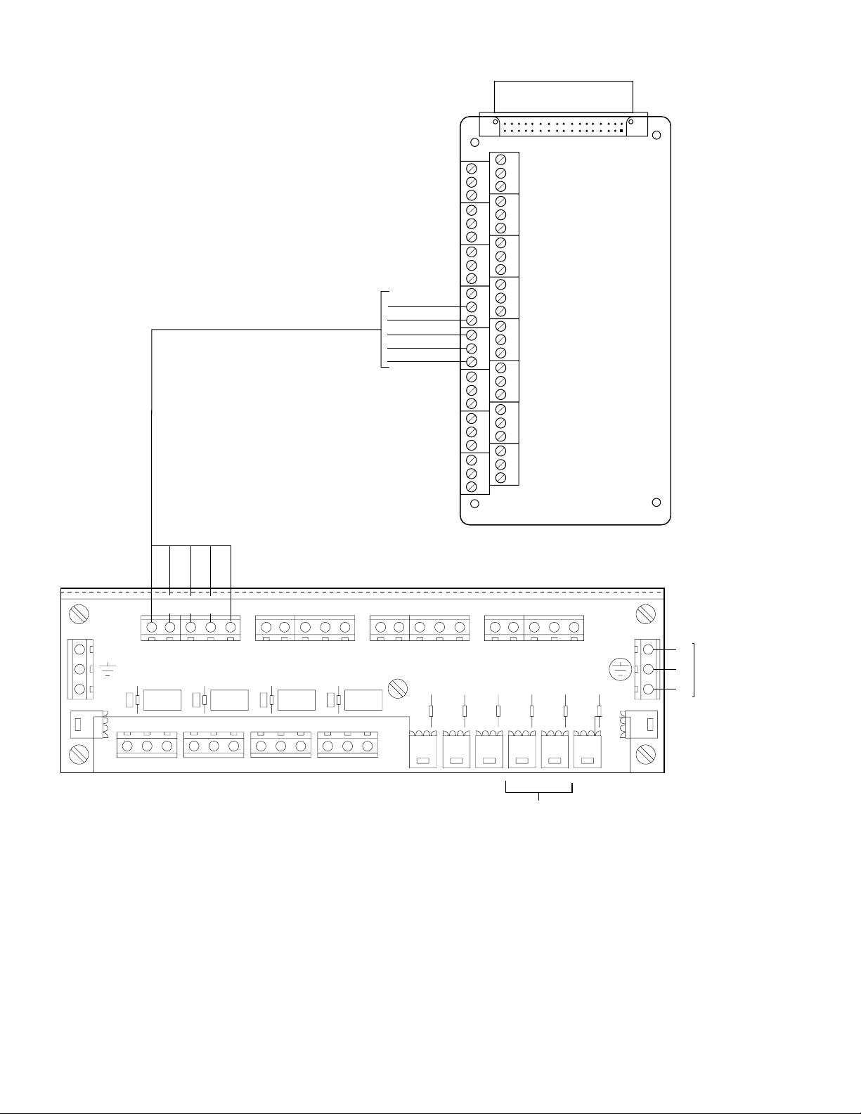
NOTE: FUSES FOR 115 VOLT MPS UNIT ARE
FAST ACTING, 1A @ 250 VAC,
SIZE: 1/4 IN. DIA X 1-1/4 IN. LG.,
GLASS BODY, NON-TIME DELAY,
BUSSMAN PART NO. BK/AGC-1
(ROSEMOUNT APRT NO. 138799-004).
INTERCONNECT
IFT
BOARD
MH1
J1
MH2
J2
FUSES FOR 220 VOLT MPS UNIT ARE
FAST ACTING, 0.5 A @ 250 VAC,
J3
SIZE 1/4 IN. DIA. X 1-1/4 IN. LG.,
GLASS BODY, NON-TIME DELAY,
BUSSMAN PART NO. BK/AGC-1/2
J4
(ROSEMOUNT PART NO. 138799-014).
CAL RET
J5
NO GAS
LO GAS
J6
HI GAS
IN CAL
J7
J8
J9
MH3
MH4
PROBE 1 PROBE 2 PROBE 3 PROBE 4
LINE OUT LINE IN
L
IN CAL
HI GAS
N
CAL RET
NO GAS
LOW GAS
HI GAS
IN CAL
CAL RET
J10
NC C NO NC C NO NC C NO NC C NO
J11
PROBE 1
PROBE 2 PROBE 3 PROBE 4
MPS TERMINATION BOARD
NO GAS
LOW GAS
PROBE 3
SOLENOID
HI GAS
IN CAL
PROBE 4
IN CAL
HI GAS
NO GAS
CAL RET
LOW GAS
PROBE 2
SOLENOID
PROBE 1
SOLENOID
J13 J14 J15 J16 J17 J18
CAL RET
SOLENOID
NO GAS
HIGH GAS
SOLENOID
LOW GAS
LOW GAS
SOLENOID
L
N
SWITCH
PRESSURE
J12
3D39120G REV
L
E
N
LINE
VOLTAGE
29850006
FUSES LOCATED BEHIND
TERMINATION BOARD
Figure 2-20. MPS Probe Wiring
IB-106-300NH
2-22

NOTE
Upon completing installation, make sure that the probe is turned on and operating prior to firing up the
combustion process. Damage can result from having a cold probe exposed to the process gases.
Power down all probes during outages. Sensor chamber is heated to 736°C. Further, if ducts will be
washed down during the outage, remove the probes to prevent water damage.
IB-106-300NH
2-23/2-24


3
SECTION III. SETUP
3-1. OVERVIEW
This section provides information on configuring the
IFT 3000 Intelligent Field Transmitter. T his section
assumes that you are familiar with the operation of
the IFT and the General User Interface (GUI). If you
need additional information on operating the IFT or
using the GUI, refer to Section V, General User
Interface, (GUI) Operation.
3-2. CONFIGURING THE ANALOG OUTPUT
Use the following procedure to configure the analog
output.
a. Press the SETUP key on the GUI keypad.
b. Set the Source to the desired measurement value
to be represented by the analog output. The
choices are O
, Efficiency, or Dual Rng O2.
2
c. Set the Type to the desired output signal style.
The choices are HART 4-20mA, 0-20mA, and
0-10V. The choice selected must agree with the
position of the current/voltage selector switch on
the IFT microprocessor board. An invalid choice
will be discarded. Note that if you are using
HART to communicate with the IFT, you must
set the analog output type to HART 4-20mA.
the point at which the output switches from
normal to hi gh range.
For a complete description of all parameters
associated with configuring the analog
output, refer to Table 5-5.
3-3. SETTING CALIBRATION PARAMETERS
To successfully calibrate a World Class 3000 system,
several calibration parameters must be set. These
parameters are generally set once and left at those
values. These values should only be changed if the
system is not ca librating p roperly, o r when chan ging
test gas bottles.
a. Press the SETUP key on the GUI keypad.
b. Select the Calibration sub-menu.
c. Set the High Gas parameter to the oxygen
concentration of the high calibration gas. For
high calibration gas, 8% oxygen with a balance
of nitrogen is recommended.
d. Set the Low Gas parameter to the oxygen
concentration of the low calibration gas. For lo w
calibration gas, 0.4% oxygen with a balance of
nitrogen is recommended.
d. The next choice, Range Setup, will vary based
on the source selected.
Source set to Efficiency. No range setup is
1.
allowed when the source is set to
efficiency. Analog output range is fixed at
0-100% efficiency.
Source set to O
2.
. Range setup allo ws yo u to
2
set the transfer function (Xfer Fnct) to
either linear or log output. You can also
specify the O
values represented by the
2
high and low analog output values.
Source Set to Dual Rng O
3.
. Range setup
2
allows you to set the transfer function (Xfer
Fnct) to either linear or log output. You can
also specify the O
values represented by
2
the high and low analog output values for
both the normal and high range.
The Mode Setup sub-menu contains entries
for setting the range mode, whether the
high range is used during calibration, and
e. The Auto Cal parameter determines whether the
IFT performs automatic or semiautomatic
calibrations. In order to perform automatic
calibration, the system must be equipped with an
MPS 3000 Multiprobe Calibration Gas
Sequencer. To perform automatic calibrations,
set the Auto Cal parameter to Yes.
f. The Output Tracks setting determines whether
the analog output tracks the oxygen reading
during a calibration. Setting Output Tracks to No
locks the analog output value to the last
measured oxygen reading until the calibration is
complete.
g. The Cal Interval parameter sets the time in hours
and days between automatic calibrations. When
Auto Cal is set to NO, this parameter is set to
OFF.
h. The Next Cal parameter displays the time until
the next scheduled automatic calibration. If
automatic calibration is not enabled, this
parameter displays Disabled.
IB-106-300NH
3-1

i. The Gas Time parameter sets the amount of time
that calibration gas flows during an automatic
calibration before a reading is taken. This value
is not used for semiautomatic calibrations.
j. The Purge Time parameter sets the amount of
time after an automatic calibration before the
system is returned to normal operation. This
allows time for the calibration gases to clear the
lines and the system to return to the process gas
concentration. This value is not used for
semiautomatic calibrations.
k. The Res Alarm parameter displays the setpoint
for the Res Hi alarm. Do not change this
parameter unless directed by a qualified
Rosemount Service Engineer.
3-5. CONFIGURING EFFICIENCY
CALCULATIONS
To enable efficiency calculations and set the efficiency
constants, press the SETUP key on GUI keypad, and select
the Efficiency Calc sub-menu. The Enable Calc selection
turns efficiency calculation on and off. Enter the K1, K2,
and L3 constant values in the appropriate fields. Efficiency
constant values are listed in
Table 5-6 for oil and gas for the US and Europe.
3-6. CONFIGURING THE RELAY OUTPUTS
The IFT has two relays that can be individually
configured. Each relay can be triggered by three
separate events selected from a list of eight events.
Use the following procedure to configure the relay
outputs.
l. Press the ESC key twice to return to the Main
menu.
3-4. SETTING THE O
ALARM SETPOINTS
2
The IFT has a high and low O2 alarm. To change the
alarm setpoints, press the SETUP key on the GUI
keypad and select the O
Alarms sub -me n u.
2
The Hi Alarm and Lo Alarm values are the settings
for the high and low oxygen concentration alarms,
respectively. The Alarm DB parameter allows the
setting of an alarm dead band. When a dead band is
set, the O
value must change by the d ead b and value
2
before the alarm will reset. For example, if the Hi
Alarm is set to 8.00% and the dead band is set to
0.25%, the O
7.75% before the O
concentration must drop to below
2
alarm will clear. This prevents
2
the alarms from continually activating and clearing
when the oxygen value is near the alarm setpoint.
a. Press the SETUP key on the GUI keypad. Select
the Relay Outputs sub-menu.
b. Select K1 Setup or K2 Setup to configure rela y
one or relay two, respectively.
c. Set Event 1, Event 2, and Event 3 to the d esired
triggering event. The relay will be energized
when any of the three events occurs. If you do
not want a relay to trigger on three events, set the
desired trigger or triggers and set the remaining
events to Off.
Note that the TG Low event will only function if
the system includes an MPS 3000 Multiprobe
Test Gas Sequencer.
d. Press the ESC key and select the other relay.
Configure the relay as described above.
e. Press the ESC key three times to return to the
Main menu.
IB-106-300NH
3-2

4 4
SECTION IV. CALIBRATION
4-1. ANALOG OUTPUT CALIBRATION
For the analog output to perform within the published
specifications, it must be manually calibrated. The
only equipment needed to perform the calibration is a
voltage or current meter, depending on which mode
of operation is to be calibrated. Prior to manual
calibration, remove the IFT from any control loops it
may be in.
Prior to manual calibration, the IFT
should be removed from any automatic
control loops. Failure to remove the IFT
from control loops prior to calibration
may result in faulty equipment
performance.
Once initiated from the Setup - Analog Outputs
menu, the calibration procedure is self guiding.
4-2. SYSTEM CALIBRATION
a. Overview. The primary purpose of an oxygen
analyzer is to give an accurate representation of
the percentage of O
in the gas stream. The
2
system should be calibrated periodically to
maintain an accuracy which may otherwise be
reduced over time due to cell aging.
A requirement for calibration is a set of two
accurate calibration gases spanning the oxygen
range of most interest. For example, 0.4% and
8% for a 0-10% oxygen range.
Under normal conditions the probe should not
need frequent calibration. Because calibration is
necessary, the system can be equipped with the
optional MPS 3000 Multiprobe Calibration Gas
Sequencer for fully automatic calibration at
regular intervals. Without an MPS, the probes
must be calibrated manually (semiautomatically).
b. Probe Calibration
Previous Calibration Constants
1.
Functionality. There are three sets of
registers used to store calibration
constants. These are: Latest Calibration,
Previous Calibration, and Calculation. Only
the values in the Calculation register are
used to calculate the oxygen value for
display and representation on the analog
output signal. These values may be changed
in two ways.
(a) The operator may change the values
through the SETUP menu. The
operator may adjust the slope and
constant individually, or reset both to
the values calculated during the last
good calibration. To reset the values,
move the cursor to RESET SLOPE &
CONST and push ENTER.
(b) The IFT will automatically change the
values after each calibration as
follows:
The values in the Latest Calibration
registers are updated after every
complete calibration, even if the
calibration is not successful. If the
calibration is successful, the values in
the Latest Calibration registers are
copied into the Previous Calibration
registers. This is accomplished prior
to the update of the Latest Calibration
registers. The new slope and constant
are copied into the Calculation
register.
If the calibration fails, the Previous
Calibration registers retain their
existing values, while the Latest
Calibration registers record the values
of the failed calibration. The
Calculation register is not updated
when the calibration fails.
Calibration Methods. There are three
2.
calibration methods: manual
(semiautomatic), manually initiated
automatic, and fully automatic. Manual
(semiautomatic) calibration is done without
an MPS unit. Calibration gases are
switched on and off by the operator and the
IFT is sequenced through the calibration
procedure by the operator with the front
panel keyboard. The IFT prompts the
operator for the correct action. Manually
initiated automatic calibration is done with
an MPS. The operator manually initiates
the calibration at the IFT or through a
remote switch, and the IFT controls the
IB-106-300NH
4-1

operation of the MPS unit and the
calibration sequencing. Fully automatic
calibration requires no action from the
operator. The setup is the same as
semiautomatic except the IFT automatically
initiates the calibration at a fixed calibra tion
interval. In this mode the operator can also
manually initiate calibrations between the
intervals in the same manner as
semiautomatic calibrations.
c. Manual (Semiautomatic) Calibration.
Calibration Gases For Manual (Semi-
1.
automatic) Calibration. There are two
options for supplying calibration gases to
the probe during semiautomatic calibration.
The first "A" uses refillable bottles and
adjustable 2-stage pressure regulators; the
second "B" uses disposable bottles and a
fixed single stage regulator to provide a
mixed flow. Normally, the first (method
"A") will have a higher cost and not be
portable. The second ("B") is less costly,
portable, and weighs about 10 lbs (4.5 kg).
LIQUID CARBONIC GAS
CORP.
SPECIALTY GAS
LABORATORIES
700 South Alameda Street
Los Angeles, California 90058
213/585-2154
767 Industrial Road
San Carlos, California 94070
415/592-7303
9950 Chemical Road
Pasadena, Texas 77507
713/474-4141
12054 S.W. Doty Avenue
Chicago, Illinois 60628
312/568-8840
Test Method "A" Fixed Tanks
and Manifolds.
(a) Required Equipment.
Do not use 100% nitrogen as a zero gas.
It is suggested that gas for the zero be
between 0.4% and 2.0% O2. Do not use
gases with hydrocarbon concentrations
of more than 40 parts per million.
Failure to use proper gases will result in
erroneous readings.
NOTE
Ambient air is not recommended for use as
high calibration gas. An 8% O
balance in
2
nitrogen is recommended for high
calibration gas.
1 Two tanks of precision
calibration gas mixtures.
Recommended calibration gases
are nominally 0.4% and 8.0%
oxygen in nitrogen.
Two sources of calibrated gas
mixtures are:
603 Bergen Street
Harrison, New Jersey 07029
201/485-1995
255 Brimley Road
Scarborough, Ontario, Canada
416/266-3161
SCOTT ENVIRONMENTAL
TECHNOLOGY, INC.
SCOTT SPECIALTY GASES
2600 Cajon Blvd.
San Bernardino, CA 92411
714/887-2571
TWX: 910-390-1159
1290 Combermere Street
Troy, MI 48084
314/589-2950
Route 611
Plumsteadville, PA 18949
215/766-8861
TWX: 510-665-9344
2616 South Loop, West
Suite 100
Houston, TX 77054
713/669-0469
IB-106-300NH
4-2

2 If gas bottles will be permanently
hooked up to the probe, a manual
block valve is required at the
probe (between the calibration
fitting and the gas line) to prevent
the migration of process gases
down the calibration gas line.
If an MPS 3000 Multiprobe Gas
Sequencer is used, a check valve
is required at the probe.
3 Two, 2-stage pressure regulators
with stainless steel diaphragms
for tanks. Maximum output
required: 20 psi (138 kPa).
4 One instrument air pressure
regulator: 20 psi (138 kPa)
maximum and a supply of clean,
dry instrument air.
5 Two zero-leakage shutoff valves.
can cause back diffusion of
oxygen fro m the atmosphere e ve n
though positive pressures are
maintained in the lines.
NOTE
The probe calibration gas fitting has a seal
cap which must be in place at all times
except during calibration.
In addition to the precision
calibration gas mixtures, clean,
dry, oil-free instrument air should
be used for calibration.
For optimum accuracy, this calibration
should be run with the process at
normal temperature and operating
conditions.
6 Miscellaneous oil-free tubing and
fittings.
(b) Calibration.
1 A typical calibration setup is
shown in Figure 4-1. Care must
be taken that all fittings are tight
and free from oil or other organic
contaminants. Small openings
CALIBRATE
INPLACE
FITTING
5 SCFH
FLOW METER
LEA TIGHT
VALVES
REG
CHEC
VALVE
PROBE
END VIEW
REFERENCE AIR
CONNECTION
When the calibration gas line
exceeds 6 ft (1.8 m) in length
from the leak tight valves, check
valve, Rosemount P/N
6292A97H02, should be installed
next to the calibration gas
connection on the probe to
prevent breathing of the line with
the process gas and subsequent
gas condensation and corrosion.
2 SCFH
REFERENCE
AIR
SET
INSTR.
AIR
IN
0.4
O
2
PROBE CALIBRATION GAS FITTING
NOTE
HAS A SEAL CAP WHICH MUST
BE IN PLACE AT ALL TIMES
ECEPT DURING CALIBRATION.
Figure 4-1. Typical Calibration Setup
.0
O
2
IB-106-300NH
4-3

NOTE
Only set the calibration gas flowmeter upon
initial installation and after changing the
diffusion element. A slightly lower
calibration gas flow rate may indicate a
plugged diffusion element.
2 Set the calibration gas pressure
regulators and the flow meter for
a flow of 5 SCFH at 20 psi (138
kPa) for both gases. The
reference air should be flowing as
in normal operation.
3 Refer to paragraph 4-2.d of this
section for Manual
(Semiautomatic) Calibration
setup and procedure using the
IFT.
4 Calibration gases will be
switched on and off using the
shutoff valve s.
Test Method "B" Rosemount Oxygen
Calibration Gas and Service Kit.
(a) Required Equip ment
Do not use 100% nitrogen as a zero gas.
It is suggested that gas for the zero be
between 0.4% and 2.0% O2. Do not use
gases with hydrocarbon concentrations
of more than 40 parts per million.
Failure to use proper gases will result in
erroneous readings.
NOTE
Ambient air is not recommended for use as
high calibration gas. An 8% O
balance in
2
nitrogen is recommended for high
calibration gas.
CALIBRATION
GAS KIT #1
(P/N 6296A27G01)
27270007
Figure 4-2. Portable Rosemount Oxygen Calibration
Gas Kit
2 Extra gas bottles are available at:
Rosemount Analytical Inc.
Box 901
Orrville, Ohio 44667
U.S.A.
Rosemount Limited
Burymead Road
Hitchin, Herts. U.K.
Rosemount Italy
VIA Guido Cavalcanti 8
20127 Milan, Italy
Rosemount Spain
Saturnino Calleja 6
28002 Madrid
Spain
Rosemount France
165 Boulevard de Vallmy
92706, Colombes, France
1 Portable Rosemount Oxygen
Calibration Gas Kits (Figure 4 -2),
Rosemount P/N 6296A27G01,
containing 8% and 0.4% gases in
a portable carrying case with
regulator, b uilt-i n val ve, ho se and
connecting adapter to the
calibration gas connection.
IB-106-300NH
Rosemount P/N 3530B07G01 for
probe 0.4 % oxygen in nitr ogen in
disposable bottle.
Rosemount P/N 3530B07G02 for
probe 8% oxygen in nitrogen in
disposable bottle.
4-4

3 A check valve is required at the
probe (between the calibration
fitting and the gas line) to prevent
the migration of process gases
down the calibration gas line.
(b) Calibration with a Portable
Rosemount Oxygen Calibratio n Ga ses
Kit.
1 A typical portable calibration
setup is shown in Figure 4-3. For
manual (semiautomatic)
calibrati on, remove cap plug from
the calibrate in place fitting. The
cap plug must be retained to seal
this fitting after calibration is
complete; failure to do so may
render the probe useless if the
system pressure is slightly
negative. The reference air should
be flowing as in normal
operation.
d. Manual (Semiautomatic) Calibration
Procedure. The following procedure relates to
an operator initiated calibration selected at the
IFT by pressing the CAL key. The calibratio n is
manually performed by the operator upon data
queues from the IFT. Any system without an
MPS 3000 Multiprobe Calibration Gas
Sequencer must follow these steps.
Press SETUP to display the SET UP menu.
1.
Select PROBE CALIBRATION sub-menu.
Ensure that Auto Cal is disabled. Set the
cursor on Auto Cal. Press ENTER. Set
Auto Cal to NO if not already done.
Press the CAL key. Select PERFORM
2.
CALIBRATION sub-menu. "Press ENTER
to start Manual Calibration" will appear on
the LCD display. Press ENTER to start.
Follow the data queues. Refer to Table 5-4,
CALIBRATE O
Sub-menu.
2
e. Fully Automatic Calibration.
2 Refer to paragraph 4-2.d of this
section for Manual
(Semiautomatic) Calibration
setup and procedure using the
IFT.
3 Screw the pushbutton regulator
with contents gage on to the
calibration gas of choice and
inject the calibration gas by
opening the valve. Gas is on
continuously when the valve is
opened.
CALIBRATE
IN PLACE
CONNECTION
GAGE - SET 5 SCFH
NOTE:
PROBE CALIBRATION GAS
FITTING HAS A SEAL CAP
WHICH MUST BE IN PLACE
EXCEPT DURING CALIBRATION.
CHECK
VALV E
PUSHBUTTON
REGULATOR
WITH CONTENTS
REFERENCE AIR
CONNECTION
CALIBRATION
GAS HOSE
CONNECTS
TO CHECK
VALV E
0.4
%
O
2
Figure 4-3. Typical Portable Calibration Setup
8.0
%
O
2
27270005
Calibration Gases For Fully Automatic
1.
Calibration. For fully automatic calibratio n,
an MPS 3000 Multiprobe Calibration Gas
Sequencer is required as well as the two
types of calibration gas.
Do not use 100% nitrogen as a zero gas.
It is suggested that gas for the zero be
between 0.4% and 2.0% O2. Do not use
gases with hydrocarbon concentrations
of more than 40 parts per million.
Failure to use proper gases will result in
erroneous readings.
NOTE
Ambient air is not recommended for use as
high calibration gas. An 8% O
balance in
2
nitrogen is recommended for high
calibration gas.
Two tanks of precision calibration gas
mixtures. Recommended calibration gases
are nominally 0.4% and 8.0% oxygen in
nitrogen set calibration gas pressure at 20
psi (138 kPa).
A typical automatic calibration system is
shown in Figure 4-4.
IB-106-300NH
4-5

OPTIONAL
CHECK
VALV E
CALIBRATION GAS
MPS
PROBE
(END VIEW)
REFERENCE
HPS
MPS-IFT
SIGNAL
CONNECTIONS
AIR
PROBE
SIGNAL CONNECTIONS
IFT
INSTRUMENT
AIR IN
NOTE: THE MPS CAN BE USED WITH UP
TO FOUR PROBES. ONLY ONE PROBE
CAN BE CALIBRATED AT A TIME.
PROBE CALIBRATIONS MUST BE
SCHEDULED IN MULTIPLE PROBE
APPLICATIONS.
NOTE: SHOWN WITH HPS OPTION.
Figure 4-4. Typical Automatic Calibration System.
CALIBRATION
GAS 1
(HIGH )O
2
CALIBRATION
GAS 2
(LOW O )
2
27270006
IB-106-300NH
4-6

Table 4-1. Automatic Calibration Parameters
Auto Cal YES/NO Set to YES
Output Tracks YES/NO
Set as desired t o configure
analog output tracking.
Cal Intvl XD XH
Set the desired time between
calibrations in number of days
and hours (1 year max).
Next Cal. XD XH Displays the time left to the start
of the next calibration. Set the
desired time until the start of the
next calibration (1 year max). If
nothing is entered here, the unit
will automatically enter the Cal
Intvl and count down from that.
Gas Time 0:00 Set the amount of time for
calibration gases to be turned on
in minutes and seconds; allow
enough time for signal value to
stabilize.
Gas Time 0:00 Set the amount of time for
calibration gases to be turned on
in minutes and seconds; allow
enough time for signal value to
stabilize.
Purge Time 0:00 Set the amount of time for the
gas lines to clear in number of
minutes and seconds.
Abort Time 0:00 Set the amount of time allowed
between ke y functions before the
calibration procedure is aborted
in number of minutes and
seconds.
Res Alarm ____
Set the desired resistance alarm
between 50 to 10,000 ohms.
Fully Automatic Calibration Setup. In
2.
order for the IFT system to calibrate
automatically, the parameters from the
CALIBRATE sub-menu (shown in Table
4-1) in the IFT have to be entered.
Once these parameters have been set, the
system will initiate calibration without
operator intervention as set by the CAL
INTVL parameter.
Manually Initiated Fully Automatic
3.
Calibration Procedure. The following
procedure relates to an operator initiated
calibration, either by a remote switch
(CAL INIT on interconnect board) or
selected at the IFT by pressing the CAL
key using an MPS 3000 Multiprobe Gas
Sequencer.
(a) Press SETUP to display the SETUP
sub-menu. Select Calibration.
Ensure that Auto Cal is enabled. Set
the cursor on Auto Cal. Press
ENTER. Set Auto Cal to YES if not
already done.
(b) Press the CAL key. Select Perfor m
Calibration. "Press ENTER to start
Automatic Calibration" will appear
on the LCD display. Pre ss ENTER
to start. Refer to Table 5-5,
CALIBRATE O
Sub-Menu.
2
IB-106-300NH
4-7/4-8


5 5
SECTION V. GENERAL USER INTERFACE (GUI) OPERATION
5-1. OVERVIEW
Ensure that the oxygen analyzer, heater power
supply, and intelligent field transmitter have been
properly connected. It is important to check that
grounding and screening of terminations are correctly
made to prevent the introduction of ground loops.
The IFT is equipped with noise suppression circuitry
on the power supply and signal input lines. Proper
grounding at installation will ensure accuracy of
function.
The following five languages are can be selected
within the IFT:
English Italian
French Spanish
German
NOTE
Support the keypad with the free hand to
prevent bounce back of the IFT door.
a. Intelligent Field Transmitter (IFT). The
Intelligent Field Transmitter may be supplied
with either of two configurations. These are the
blind version and the deluxe version. The two
versions differ as follows:
eight-key pad from which the probe and
electronics can be configured, calibrated
and troubleshooted.
b. HART Communicator Interface Devices. The
HART communications protocol can interface
with any of the above IFT versions. To interface
a HART communicator with an IFT, one of three
interface devices is required. The interface
devices are as follows:
Rosemount Model 275 Handheld Commu-
1.
nicator. The handheld communicator
requires Device Descriptor (DD) software
specific to the World Class 3000 product.
The DD software will be supplied with
many model 275 units, but can also be
programmed into existing units at most
Fisher-Rosemount service offices.
Personal Computer (PC). The use of a
2.
personal computer requires Cornerstone
software with Module Library (ModLib)
specific to the World Class 3000 product.
Selected Distributed Control Systems. The
3.
use of distributed control systems requires
input/output (I/O) hardware and software
which permit HART communications.
Blind Version. The blind version has no
1.
display and no keypad. With this version an
external HART communications device is
required.
Deluxe Vers i on (GUI). The deluxe version
2.
is also known as the General User Interface
(GUI) version. This IFT contains an LED
display, liquid crystal display panel, and an
This section of the manual deals with operator
controls and displays available with the GUI
equipped IFT. Operating parameters are listed
and instructions are included for viewing and
changing them.
Any procedures not associated with normal
operation are included in Section II, I nstallation,
or Section V, Troubleshooting.
IB-106-300NH
5-1
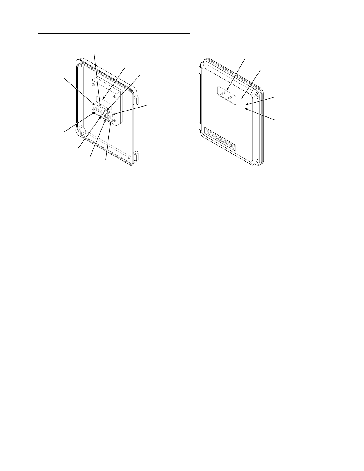
5-2. DELUXE VERSION IFT DISPLAYS AND CONTROLS
3
1
2
H
E
LP
D
A
TA
C
A
ESC
L
SET
U
P
EN
T
E
R
INTERNAL VIEW
4
5
IFT COVER DOOR
NOTE
SHOWN FOR
REFERENCE.
EXTERNAL VIEW
Figure 5-1. Deluxe Version IFT Displays and Controls
Figure 5-1
Index No. Control/LED
Description
1 LCD Display Top line displays system status, menu, and probe number.
CAL
TGH
TGL
10
11
12
13
2110003
2 HELP Context sensitive HELP is displayed when this key is pres sed.
3 DATA DATA key is used to access DATA menu.
4 CAL C AL key used to access CALIBRATE menu.
5 SETUP SETUP key used to access SETUP menu.
6 ESC The escape key is used to exit to a high level menu or to abort a parameter change.
7
∨
The decrease key is used to move the cursor (asterisk) when scrolling through lists or to
decrease a parameter value.
8
∧
The increase key is used to move the cursor (asterisk) when scrolling through lists or to
increase a parameter value.
9 ENTER The ENTER key is used to select a lower level menu, initiate calibration, or select a
parameter to change.
10 LED Display Indicates current O
or calibration gas value.
2
11 CAL Calibration in progress indicator light.
12 TGH High calibration gas indicator light. High calibration gas is being used in calibration
process.
13 TGL Low calibration gas indicator light. Low calibration gas is being used in calibration
process.
IB-106-300NH
5-2

Table 5-1. Sample HELP Messages
MENU, SUB-MENU, HELP
OR PARAMETER NAME MESSAGE
PROBE DATA Press ENTER key to access DATA menu.
CALIBRATE O
2
The CAL menu is used to start calibration and view calibration.
SETUP The SETUP menu is used to configure the IFT 3000.
5-3. HELP KEY
The HELP key will display explanatory
i. ResHi - Resistance is above the high limit.
j. OK - System is functioning correctly.
information about a menu, sub-menu, or parameter
that the asterisk is next to when pressed. The HELP
key is not available during calibration routines.
5-5. QUICK REFERENCE CHART
Refer to Table 4-1 for sample HELP messages.
The quick reference chart (Figure 5-2) is designed
5-4. STATUS LINE
to help you get where you want to be in the menu
system. The chart shows all the available menu and
The top line of the LCD display (1, Figure 5-1) is a
status line that always disp la ys s yste m stat us, men u
name, and O
level. System status displays will be
2
displayed one at a time in priority sequence, as
follows:
sub-menu options for the IFT. Follow the lines to
determine which menu choices to make. Moving
down a level on the chart is accomplished by the
use of the ENT ER key. To move up a leve l on the
chart, press the ESCAPE key.
a. Off - The probe has been turned off because
the IFT cannot control the heater temperature.
b. PrbEr - The probe is disconnected, cold, or
leads are reversed.
5-6. MAIN MENU
When power is first applied to the IFT, the MAIN
menu (Table 5-2) is initially displayed. It is from
the MAIN menu that the PROBE DATA (Table
c. HtrEr - Heater error.
5-3), CALIBRATE O2 (Table 5-4),and SETUP
(Table 5-5) menus can be accessed.
d. InCAL - Calibration in progress.
e. Low O2 - O
value is below the low alarm
2
limit.
f. HiO2 - O
value is above the high alarm limit.
2
g. NoGas - Calibration gas pressure is low.
h. CalEr - Calibration error.
IB-106-300NH
5-3
Table 5-2. MAIN menu
MENU SELECTION DESCRIPTION
PROBE DATA Refer to Table 5-3.
CALIBRATE O
2
Refer to Table 5-4.
SETUP Refer to Table 5-5.

5-7. PROBE DATA SUB-MENU
The PROBE DATA sub-menu is a list of all the
parameters of the system as it is currently
configured. To access the PROBE DATA submenu, press the DATA key at any time. The
increase and decrease keys are used to scroll
through the list. The PROBE DATA sub-menu can
be viewed but not changed. The operator must use
the SETUP menu to change any of the parameters.
There are two selections available on the PROBE
DATA sub-menu; Process Data and Diagnostic
Data. Refer to Table 5-3 for contents of the submenu.
5-8. CALIBRATE O
SUB-MENU
2
The CALIBRATE O2 sub-menu (Table 5-4) is
used to enter the calibration mode. To access the
CALIBRATE O
sub-menu, press t he CAL key at
2
any time. The increase and decrease keys are used
to scroll through the list.
The CALIBRATE O
sub-menu has three
2
selections available: Perform Calibration, View
Constants, and Calibration Status. Refer to Table
5-4 for contents of the sub-menus.
Perform Calibration has two options depending on
how Auto Cal is selected in Probe Setup. Refer to
SETUP Setting in Table 5-4.
For information on performing a calibration, refer
to Section IV, Calibration.
5-9. SETUP SUB-MENU
The SETUP sub-menu is used to enter all oper ator
set variables into the system. To access the SETUP
sub-menu press the SETUP key at any time. To
select the parameter to be changed, move the
cursor to the desired parameter using the arrow
keys. Press ENTER to select that parameter. To
change the value for that parameter, use the arrow
keys to increase or decrease the value. Press
ENTER to save changes.
There are six selections available on the SETUP
sub-menu: Calibration, O
Calculation, O2 Alarms,
2
Efficiency Calc., Relay Outputs, and Analog
Outputs. Refer to Table 5-5 for the contents of the
SETUP sub-menu, or ESCAPE to abort changes.
Table 5-3. PROBE DATA Sub-Menu
SUB-MENU
SELECTION PARAMETER DESCRIPTION
Process Data O
2
__% O
2
O2 value for the probe.
Efficiency __% Efficiency display.
Stack Temp __DegC Stack temperature.
Diagnostic Data
Temperature Cell __DegC Cell temperature of the probe.
Stack __DegC Stack temperature.
Cold Junct __DegC C old Junctio n t emperatur e.
Voltages Cell __mV Cell voltage of the probe.
Cell T/C __mV Cell thermocouple voltage of the probe.
Stk T/C __mV Stack thermocoup le voltage.
Cold Jnt __mV Cold junction voltage.
Output Values Analog __% FS Analog output voltage.
K1 State OFF/ON Status of relay 1.
K2 State OFF/ON Status of relay 2.
IB-106-300NH
5-4
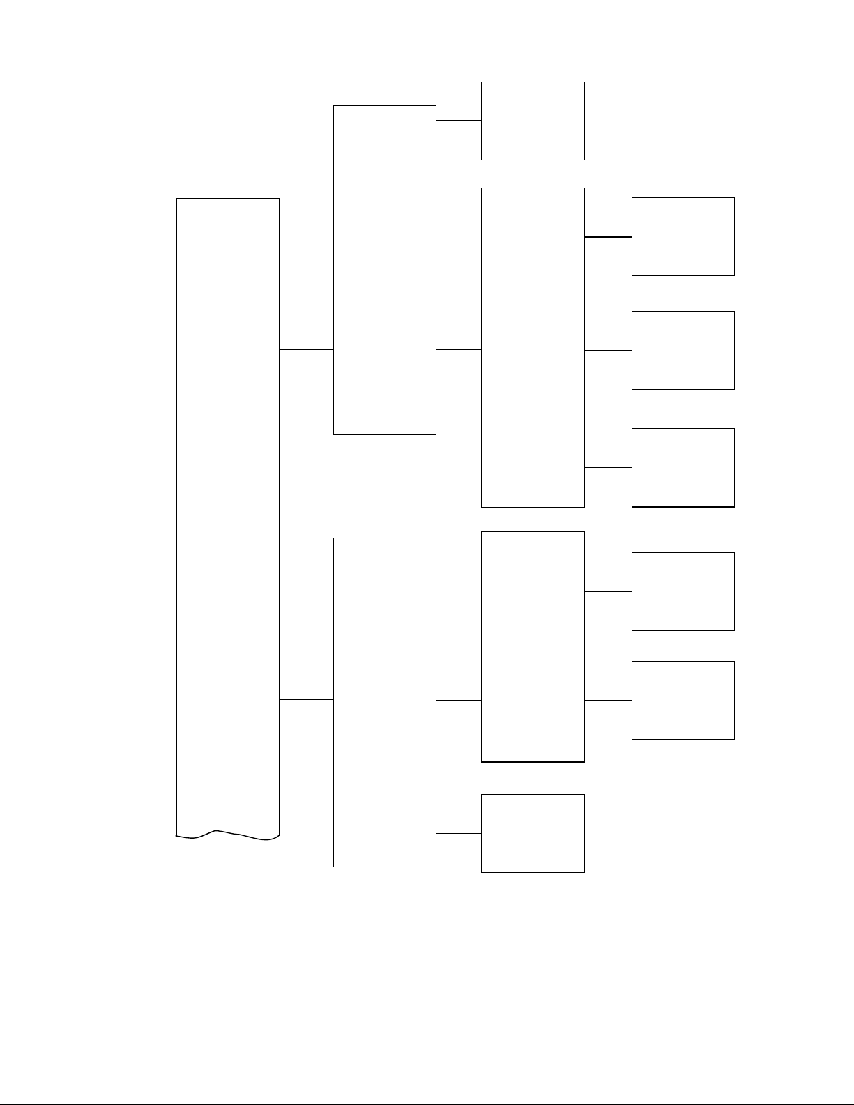
PROCESS DATA
PROBE DATA DIAGNOSTIC
DATA
O2
Efficienc
Stack Temp
TEMPERATURE
VOLTAGES
OUTPUT
VALUES
Cell
Stack
Cold unct
Cell
Cell TC
Stk TC
Cold nt
Analog
1 State
2 State
CALIBRATE O2
CONTINUE D ON
SHEET 2
PERFORM
CALIBRATION
VIEW
CONSTANTS
CALIBRATION
STATUS
LATEST
CALIBRATION
PREVIOUS CAL
Net Cal
Slope
Constant
Resist
Figure 5-2. Quick Reference Chart (Sheet 1 of 5)
Slope
Constant
Resist
Slope
Constant
Resist
022
IB-106-300NH
5-5
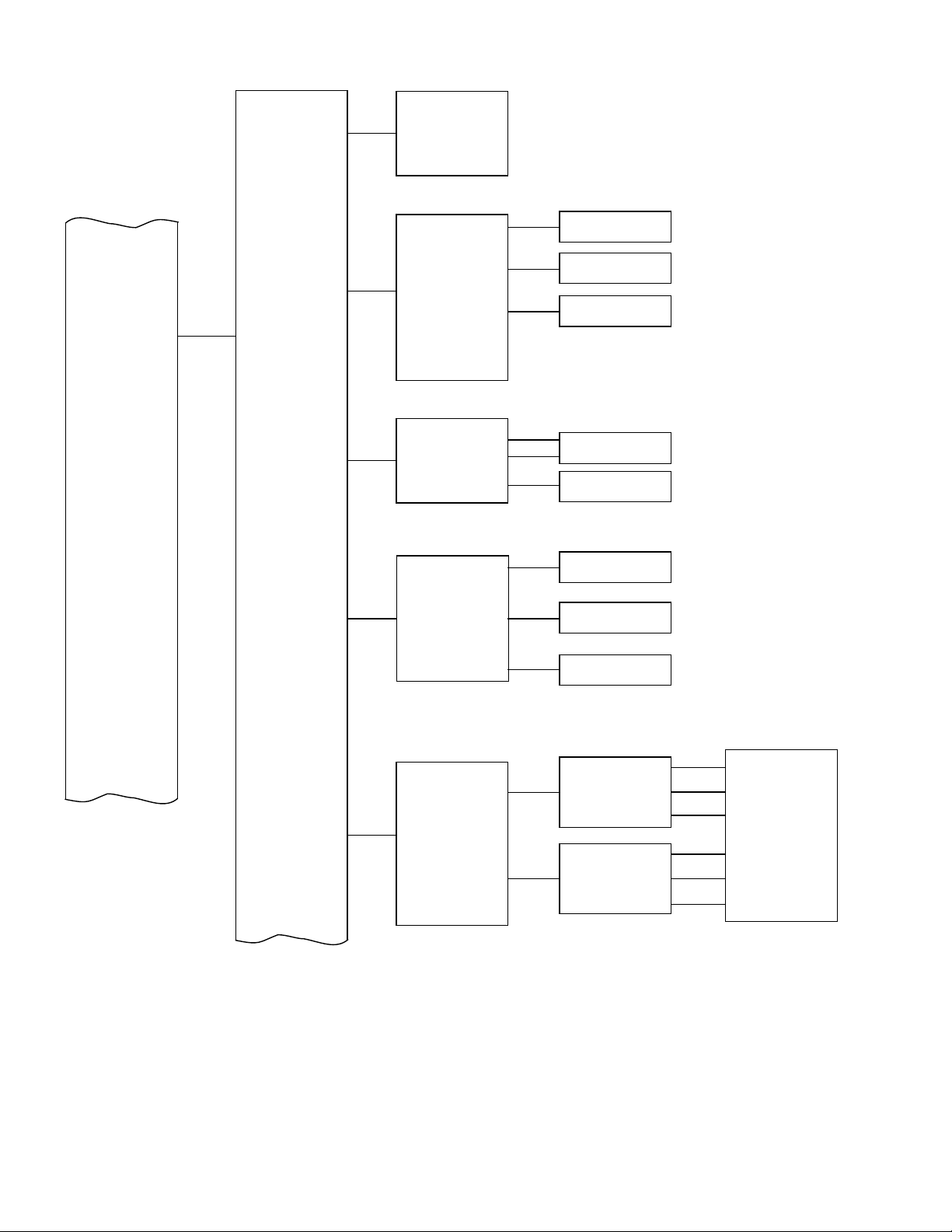
CONTINUE D FROM
SHEET 1
CALIBRATION
See seet 4
SLOPE
34.5 mVD
5.5 mVD
SETUP
O2 CALIBRATION
O2 ALARMS
EFFICIENC
CALC
CONSTANT
SET POINT
RESET SLOPE
AND CONST
HI ALARM
LO ALARM
ALARM DB
ENABLE CALC
1 V ALUE
2 V ALUE
3 V ALUE
20.0 mV
20.0 mV
o
3 C
o
43 C
0.1000 O2
25.00 O2
0.00 O2
25.00 O2
es
No
0.0000
1.000
0.0000
20.00
CONTINUE D ON
SHEET 3
1 SETUP
RELA OUTPUT
2 SETUP
CONTINUE D ON
SHEET 3
Figure 5-2. Quick Reference Chart (Sheet 2 of 5)
IB-106-300NH
5-6
EVENT 1
EVENT 2
EVENT 3
EVENT 1
EVENT 2
EVENT 3
Off
In Cal
Hi O2
Lo O2
Htr Fail
Cal Fail
TG Low
Cell Res
Hig Range
10023

(CONTINUED FROM
SHEET 2)
(CONTINUED FROM
SHEET 2)
ANALOG
OUTPUTS
SOURCE
AOUT TYPE
O2
Efficiency
Dual Rng O2
HART 4-20 mA
0-20 mA
0-10 V
SETUP
RANGE SETUP
USA
GBR
COUNTRY
FRA
ESP
GER
Figure 5-2. Quick Reference Chart (Sheet 3 of 5)
See sheet 5
27270004
IB-106-300NH
5-7
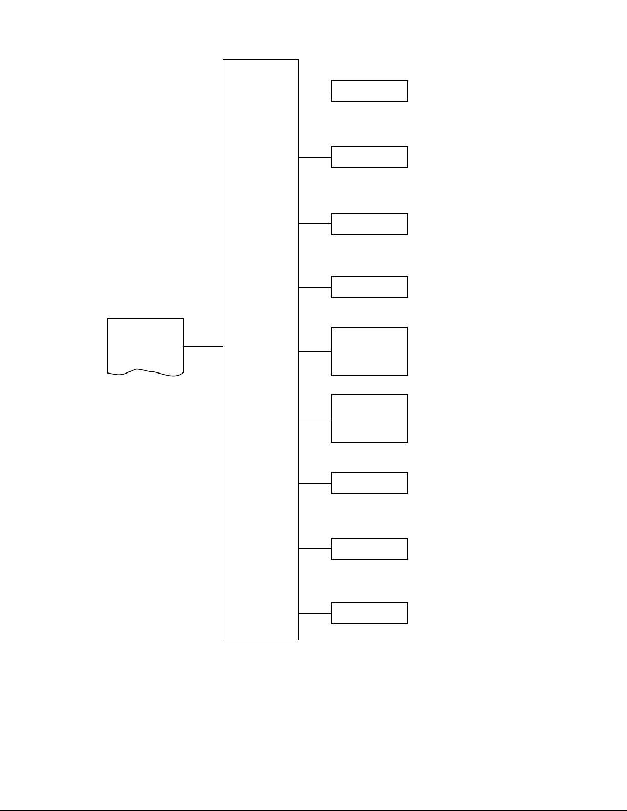
HIGH GAS
0.1000 O2
25.00 O2
CALIBRATION
CONTINUE D FROM
SHEET 2
LOW GAS
AUTO CAL
OUTPUT TRACS
CAL INTRVL
NET CAL
0.1000 O2
25.00 O2
es
No
es
No
Off
1H
35 D OH
Disabled
1H
35 D OH
1 our to 35 das
and no ours
1 our to 35 das
and no ours
GAS TIME
PURGE TIME
RES ALARM
0030
2000
0030
2000
50
10000
Ω
Ω
Figure 5-2. Quick Reference Chart (Sheet 4 of 5)
IB-106-300NH
5-8
10025

Range Setup
Source not set to
Dual Rng O2
CONTINUE D FROM
SHEET 3
FER FNCT
RANGE VALUES
Log
LIN
HIGH END
0.000 O2
25.00 O2
RANGE SETUP
Source not set to
Dual Rng O2
Range Setup
FER FNCT
NORMAL RANGE
VALUES
LOW END
Log
LIN
HIGH END
LOW END
MODE SETUP
0.000 O2
25.00 O2
0.000 O2
25.00 O2
0.000 O2
25.00 O2
RANGE MODE
Normal
Auto
Hig
DUAL RANGE
SETUP
HIGH RANGE
VALUES
Figure 5-2. Quick Reference Chart (Sheet 5 of 5)
IB-106-300NH
5-9
HIGH IN CAL
SWITCHES AT
LOW END
HIGH END
es
No
0.000 O2
25.00 O2
0.000 O2
25.00 O2
0.000 O2
25.00 O2
1002

Table 5-4. CALIBRATE O2 Sub-Menu
SUB-MENU
SELECTION
Perform
Calibration
SETUP SETTING
(SEE TABLE 3-5) DISPLAY DESCRIPTION
Auto Cal in Probe
Setup is YES
Auto Cal in Probe
Setup is NO.
Press ENTER to start Auto Calibration. MPS will start calibrating probe.
Starting Automatic Calibration
High Gas _____%
Time Left 0: 0 0
O
2
Value for high
Amount of time necessary to complete
calibration gas.
O
2
the current testing phase i n min:sec.
Cell mV ______mV Cell voltage of the probe.
Low Gas _____%
Time Left 0: 0 0
O
2
Value for low
Amount of time necessary to complete
calibration gas.
O
2
the current testing phase i n min:sec.
Cell mV ______mV Cell voltage of the probe.
Resistance Check
Resistance check in progress.
Time Left 0: 0 0
Cell _____mV _____C
Cell voltage and probe temperature.
Calibration Complete
Purging 0:00
Gas lines are being purged of calibration
gas.
Cell _____mV _____C
Cell voltage and probe temperature.
Calibration Complete
Press ENTER to start Manual Calibration. Manual calibration sequence will begin
when ENTER is pressed.
Switch ON high calibration gas. Press
ENTER when ready.
High gas ______%
Press ENTER when
O
2
reading is stable.
O
2
High
calibration gas value.
O
2
Turn OFF high calibration gas and ON
low calibration gas. Press ENTER when
ready.
Low gas ______%
Press ENTER when
O
2
reading is stable.
O
2
Low
calibration gas value.
O
2
Resistance Check. Resistance check in progress.
Turn off low calibration gas. Press
ENTER when ready.
Press ENTER when probe has returned to
process.
View Constants Latest
Calibration
Previous
Calibration
Slope _____mV/D
Constant _____mV
Resist _____ohms
Slope _____mV/D
Constant _____mV
Resist _____ohms
Slope for probe from latest calibration.
Latest calibration offset for probe.
Latest calibration resistance of probe.
Slope for probe from previous calibration.
Previous calibration offset for probe.
Previous calibration resistance of probe.
Calibration Status N/A Next Cal XD XH Time until next calibration in number of
days and number of hours.
Slope _____
Constant _____
Resist _____
Status of the slope.
Status of the offset.
Status of the resistance.
IB-106-300NH
5-10

Table 5-5. SETUP Sub-Menu
SUB-MENU
SELECTION PARAMETERS DESCRIPTION
Calibration High Gas ____% O
Low Gas ____% O
2
2
Value of hi gh O2 calibration gas (0.1000% - 25.00% O2).
Value of low O2 calibration gas (0.1000% - 25.00% O2).
Auto Cal YES/NO MPS required for Auto Cal.
Output Tracks YES/NO NO, locks output during calibration.
Cal Intrvl XD XH Select time between calibrations in number of days and
hours (1 year max).
Next Cal XH Time until next calibration in number of hours
(1 year max).
Gas Time 0:30 - 20:00 Amount of time calibration gases will be turned on in
number of minutes and seconds; allow enough time for
signal values to stabilize.
Purge Time 0:30 - 20:00 Amount of time for gas lines to clear of calibration gas.
Res Alarm 50 W - 10 kW Resistance alarm set from 50 to 10,000 ohms.
O2 Calculation Slope ____ mV/D Set value between 34.5 and 57.5.
Constant ____ mV Set value between -20.0 and +20.0 mV.
Set Point ____°C Set either 736 for World Class 3000 probes or 843 for
218 probes.
Ensure the correct voltage is selected when using HPS 3000 with either World Class
3000 probes or 218 probes. Refer to Figure 2-15, Jumper Selection Label for proper
voltage selections. If incorrect SET POINT is selected, damage to the probe may
occur.
Reset slope and constants. Press ENTER to reset slo pe and constants to val ue s from
the latest successful calibration.
O2 Alarms Hi Alarm ____% O
Lo Alarm ____% O
Alarm DB ____% O
2
2
2
Set value for high alarm limit (0.1000% - 25.00%).
Set value for low alarm limit (0.1000% - 25.00%).
Set value for alarm dead band (0.0000% - 25.00%).
Efficiency Calc. Enable Calc. YES/NO Select YES to enable, NO to disable.
K1 Value _______ Set between 0.0000 and 1.000. Refer to Table 5-6.
K2 Value _______
Set between 0.0000 and 1.000. Refer to
Table 5-6.
K3 Value _______
Set between 1.000 and 20.00. Refer to
Table 5-6.
IB-106-300NH
5-11

Table 5-5. SETUP Sub-Menu (Continued)
SUB-MENU
SELECTION PARAMETERS DESCRIPTION
Relay Outputs
NOTE
K1 and K2 relay outputs can be configured for "OFF" or any one of the eight
events listed below. Up to three events can control each relay output. Events are
selected in the SETUP sub-menu.
- Off No effect.
K1 Setup Event 1 1. In Cal Probe goes into calibration status.
Event 2 2. Hi O
Event 3 3. Lo O
2
2
Output exceeds high end alarm limit.
Output goes below low alarm limit.
Event 1 4. Htr Fail Probe heater fault occurs.
K2 Setup Event 2 5. Cal Fail Probe failed last calibration.
Event 3 6. TG Low Calibration gas pressure gets too low.
7. Cell Res Probe resistance exceeds high limit.
8. High Range High analog output range is selected.
Analog Output SOURCE O
AOUT TYPE
RANGE SETUP
(Source not set to Dual Rng O2)
Xfer Fnct Log Select the transfer function used on the analog output.
Range Values
High End
0.000% O2 - 25.00% O
Low End
0.000% O2 - 25.00% O
2
Efficiency
Dual Rng O
2
Select the measurement value to be represented on the
analog output.
Select one of the listed options to define upper and lower
HART 4-20mA
0-20mA
0-10V
limits of probe analog output. Only a selection that
matches the position of the analog output selector switch
on the microprocessor board (Figure 2-9) will be accepted.
The defined limits correspond to the upper-lower %O
2
values defined in the Range Setup menu.
Lin Selecting Log will not effect the output when Efficiency is
selected as the Source.
Enter the upper and lower analog output range values. The
High End value defines the measured O
2
value
2
corresponding to the high analog output value, i.e, 20mA
or 10V, and the Low End value corresponds to the low
2
analog output value, i.e., 0mA, 4mA, or 0V.
IB-106-300NH
5-12

Table 5-5. SETUP Sub-Menu (Continued)
SUB-MENU
SELECTION PARAMETERS DESCRIPTION
Analog Output RANGE SETUP
(continued) (Source set to Dual Rng O2)
Xfer Fnct Log
Lin
Select the transfer function used on the analog output.
Selecting Log will not effect the output when Efficiency is
selected as the Source.
Normal Range Values
High End
0.000% O2 - 25.00% O
Low End
0.000% O2 - 25.00% O
Enter the upper and lower analog output range values for
Normal Operating Range. The High E nd value defines the
measured O
2
output value, i.e, 20mA or 10V, and the Low End value
corresponds to the low analog output value, i.e., 0mA,
2
4mA, or 0V.
value corresponding to the high analog
2
Dual Range Setup
Mode Setup
Range Mode Normal Forces the output to the Normal Range.
Auto Allows the IFT to select either the High Range or the
Normal Range based on the present O
Setup Values.
High Forces the output to the High Range.
High in Cal Yes/No Selecting Yes will cause the High Range to be used
whenever the probe is being calibrated.
Switches at
0.000% O2 - 25.00% O
2
Enters the switching point between the High a nd Normal
Ranges. O
values above this point will use the High
2
Range and values below this point will use the Normal
Range. The O
value must be below the switch point by
2
10% (of the "Switches at" value) to cause a switch from
High to Normal Range.
value and the Mode
2
High Range Values
High End
0.000% O2 - 25.00% O
Low End
0.000% O2 - 25.00% O
Enter the upper and lower analog output range values for
High Operating Range. The High End value defines the
measured O
2
value corresponding to the high analog
2
output value, i.e, 20mA or 10V, and the Low End value
corresponds to the low analog output value, i.e., 0mA,
2
4mA, or 0V.
NOTE: Relay output can be initiated upon range change. (See page 5-11 of Table 5-5.)
Table 5-6. Efficiency Constants
CONSTANT
UNITED STATES EUROPE
GAS OIL GAS OIL
K1 0.407 0.432 0.66 0.69
K2 0.0 0.0 0.0082 0.0051
K3 5.12 5.12 12.28 8.74
IB-106-300NH
5-13

IB-106-300NH
5-14

6 1
SECTION VI. SYSTEM TROUBLESHOOTING
6-1. OVERVIEW
The system troubleshooting describes how to identi fy
and isolate faults which may develop in the Oxygen
Analyzer System. Refer to Probe, IFT, HPS, MPS,
and HART Communicator appendices.
Install all protective equipment covers
and safety ground leads after
troubleshooting. Failure to replace
covers and ground leads could res ult in
serious injury or death.
6-2. SPECIAL TROUBLESHOOTING NOTES
a. Grounding. It is essential that adequate
grounding precautions are taken when the system
is being installed. A very thorough check must
be made at both the probe and electronics to
ensure that the grounding quality has not
degraded during fault finding. The system
provides facilities for 100% effective grounding
and the total elimination of ground loops.
suppression circuits are employed on all field
terminations and main inputs. When fault
finding, the electrical noise being generated in
the immediate circuitry of a faulty system should
be evaluated. All cable shields must be
connected to earth.
c. Loose Integrated Circuits. The IFT uses a
microprocessor and supporting integrated
circuits. Should the electronics unit receive
rough handling during installation in a location
where it is subjected to severe vibration, an
Integrated Circuit (IC) could work loose. The
fault findi ng guid es in par agraph 0 . and Tabl e 21 Appendix E, show the resulting variety of
failure modes. It is recommended that all IC 's be
confirmed to be fully seated before
troubleshooting on the system begins.
d. Electrostatic Discharge. Electrostatic discharge
can damage the IC's used in the electronics unit.
It is essential that the user ensure he/she is at
ground pote nti a l b e for e removing or ha nd li ng t he
processor board or the IC's used on it.
6-3. SYSTEM TROUBLESHOOTING
b. Electrical Noise. The IFT has been designed to
operate in the type of environment normally
found in a boiler room or control room. Noise
The status line of the GUI equipped IFT will display
one of ten conditions. The system status displa ys will
be displayed one at a time in priority sequence, as
indicated in Table 6-1.
IB-106-300NH
6-1

Table 6-1. IFT Status Codes
Off Heater power has been turned OFF by the electronics. The display shows 0% O
. Several conditions may
2
cause the OFF status:
1. The cell heater temperature is below -50°C. The thermocouple wires may be reversed.
2. The cell temperature is more than 70°C above the set point. The heater is out of control. The triac
module may have failed.
3. The cell heater thermocouple voltage has remained within +1.5 mV for more that 4 minutes. The
thermocouple may be shorted.
4. The AD590 voltage is below 50.0 mV (50K or -223°C). The AD590 is not connected.
5. The AD590 voltage is above 363 mV (363K or 90°C). If HPS is used with IFT, then IFT interconnect
board has JM1 in position connecting two AD590s in parallel.
PrbEr The probe is disconnected or cold, or leads are reversed.
HtrEr There is a fault within the heater system. The heater temperature is more than +25°C from the set point.
When the unit is first turned ON, HtrEr is normal. The heater may take 0.5 to 1.0 hours to warm up.
InCal T he system is currently undergoing calibration. If Outpu t Tr acks is set to YES, the output will show
values. If Output Tracks is set to NO, the output will hold the pre-calibration value.
2
LowO
HiO
2
changing O
2
The measured O2 value is below the low O2 alarm limit. The problem may be in the probe or the process.
The measured O2 value is above the high O2 alarm limit. The problem may be in the probe or the process.
NoGas Test gas pressu re is too low. Pressure switches are set to trig ger this alarm at 12 to 16 psig (83 to 110 kPa
gage). Test gas regulators are usually set at 20 to 25 psig (138 to 172 kPa gage). Possible causes are:
1. At least one test gas pressure switch is open.
2. A test gas cylinder is empty.
3. There is an MPS or piping failure.
4. If MPS is not connected, CALRET and NOGAS signals should be jumpered on the interconnect board.
CalEr An error occurred during the last calibration. The error may be one of the following:
The new
1.
calculated slope value is outside the range 34.5 to 57.6 mV/decade.
2. The new calculated constant value is outside the range +20.0 to -20.0 mV.
3. The test gas pressur e
switch opened during calibration.
Ensure that the proper test gases are being used, and that the gas flows are set properly. Refer to Appendix
D for additional MPS troubleshooting infor mation.
ResHi The resistance calculated during the last good calibration was greater than the High Resistance Alarm limit
set in the calibration setup. The resistance limit may be set wrong, or there is a problem with the probe.
Ok Operation appears to be normal.
(blank
screen)
6-4. HEATER PROBLEM
For all heater troubleshooting, allow at least 30
minutes for the operating temperature to stabilize.
After the warmup period, observe the system status
and the voltages of the cell TC and the cold junction
A possible failure within the IFT. Check the LED on the microprocessor board to help isolate problems.
See IFT Problem in the troubleshooting tables.
b. The displayed O
value will read 0%.
2
c. Cell TC voltages will vary from normal. These
voltages are found by accessing the proper menu.
In the IFT, use the DIAGNOSTIC DATA submenu of the PROBE DATA menu.
AD590. For heater related problems:
Refer to Table 6-2 to troubleshoot heater related
a. The status line may read: HtrEr or OFF.
problems.
IB-106-300NH
6-2

Problem
Cause
Corrective Action
Status is HtrEr or OFF.
Cell TC < 28.4 mV.
Cold Junction 273 to 330 mV (normal).
O
Display = 0%
2
1. Blown fuse or faulty wiring.
Check all fuses and wiring for continuity and repair as needed. Verify that input power jumpers are
installed correctly. Check jumpers for prop er configuration in IFT and HPS if used.
2. Heater failure.
In HPS with power OFF, check heater resistance at J2, terminals R/H. For 44 V heater, resistance should be
11 to 14 ohms. For 115 V heater, resistance should be 67 to 77 ohms. Check wiring, and replace heater if
needed. Heater resistance can also be checked at the probe junction box:
• 44 V heater: terminals 7 and 8 should measure 11 to 14 ohms.
• 115 V heater: terminals 5 and 6 should measure 67 to 77 ohms. (Terminals 6 to 7 and 6 to 8 should be
open circuits.)
3. Triac open.
Check the triac. Repair as needed.
4. Electronics failure.
First check and repair all related wiring. Check and repair electronics as needed.
5. Missing insulation around heater.
Check that insulation is in place and undamaged. Repair or replace insulation as needed.
Table 6-2. Heater Troubleshooting
Status is HtrEr or OFF.
Cell TC > 28.4 mV.
Cold Junction 273 to 330 mV (normal).
O
Display = 0%
2
1. Triac failure.
Check the triac. Repair as needed.
2. Wrong TC set point.
Check electronics manual and verify the set point; typically 1356°F (736°C).
3. Wrong heater voltage selected. HPS voltage jumpers setup wrong.
For 44 V heater, make sure JM7 is installed and JM8 is removed. For 115 V heater, JM7 is removed and
JM8 is installed. The 115 V heater has an identifying stainless steel tag attached in the junction box.
Status is HtrEr or OFF.
Cell TC < 28.4 mV.
Cold Junction < 273 mV.
O
Display = 0%
2
1. Wiring error, thermocouple wires reversed.
Verify TC wiring at junction box terminal and electronics. The yellow chromel line connects to terminal 3.
The red alumel line connects to terminal 4. Trace line through the HPS (if used) and the electronics.
Reverse wires if needed.
2. Faulty thermocouple. At a cold junction reference of 77°F (25°C), the probe TC should read about 29.3 mV.
Replace faulty thermocouple.
3. Faulty AD590. At normal ambient temperatures, cold junction sensor should be 273 to 330 mV.
Replace faulty sensor.
IB-106-300NH
6-3

Table 6-2. Heater Troubleshooting (continued)
Problem
Cause
Corrective Action
Status is HtrEr or OFF.
Cell TC = -40 mV.
Cold Junction 273 to 330 mV (normal).
O
Display = 0%
2
1. Faulty thermocouple connection or open.
Verify TC wiring at junction box terminal and electronics. The yellow chromel line connects to terminal 3.
The red alumel line connects to terminal 4. Trace line through the HPS (if used) and the electronics. Repair
connection or wiring as needed.
2. Thermocouple fault. At a cold junction reference of 77°F (25°C), the probe TC should read about 29.3 mV.
Replace faulty thermocouple.
6-5. CELL PROBLEM
For cell troubleshooting, as in heater problems, you
should allow at least 30 minutes for operating
temperature to stabilize. After this warmup period,
observe the system status and cell voltage. If the
heater is working, troubleshoot the cell. If the heater
is nor working, refer to Heater Problem, paragraph
6-4.
• The status line may read: LowO
, Hi O2, CalEr,
2
ResHi.
• Access voltage values in the proper menu. Use the
DIAGNOSTIC DATA sub-menu of the PROBE
DATA menu.
Problem
Cause
Corrective Action
Status is LowO2.
Cell mV = -127 mV.
1. Faulty cell connection or open. If the cell circuit is open, the cell output will show about -127 mV.
Check cable connection between the probe and the electronics. Check that the probe spring presses the
contact pad firmly onto the cell. Repair or replace faulty wires, spring, or connectors.
2. Electronics fault. Cell output is good, and the input to the electronics is good.
Check the electronics package. In an IFT, replace the microprocessor or interface board as needed. In a
CRE, replace the DPI board if needed.
• The displayed O
• It may be helpful to observe the calibration statu s
and parameters from the last calibration: Slope,
Constant, and Cell Resistance. In the CALIBRATE
menu, VIEW CONSTANTS shows previous
calibration values, and CALIBRATION STATUS
shows the latest values. If these values appear out
of range, perform a calibration before
troubleshooting the cell.
Refer to Table 6-3 to troubleshoot cell related
problems.
Table 6-3. Cell Troubleshooting
value will read 0% to 99%.
2
Status is ResHi or CalEr.
Cell mV = -20 to 120 mV (normal).
1. Test gas flow no t 5 scfh (2.4 L/min).
Check test gas flow and related piping. Rotameter should show 5 scfh. Adjust needle valve for correct flow
rate.
2. Incorrect test gas.
Confirm labels on test gas bottles are correct. Confirm High Gas and Low Gas values agree with labels on test
gas bottles. (Refer to menu map — SETUP-CALIBR AT ION, High Gas, Low Gas.) Check all ports, cylinders,
and gas lines for proper hookup. Change piping if necessary. Label pipes for reference.
IB-106-300NH
6-4

Table 6-3. Cell Troubleshooting (continued)
Problem
Cause
Corrective Action
Status is ResHi or CalEr.
Cell mV = -20 to 120 mV (normal).(continued)
3. Reference air contamination (oil/water).
Clean or replace lines and valves as needed.
4. Cell leads reversed.
Check cell signal wiring from probe junction box to electronics, and correct wiring if needed.
5. Reference/test gas lines reversed.
Switch piping as needed.
6. Diffusion element fault. Diffusion element cr acked, broken, missing, or plugge d.
Replace diffusor or snubber as needed. Diffusors are disposable because it is difficult to clean a diffusor
and know the tiny pores are open. A flow and pressure test with a manometer is possible but usually not
practical. To clean a snubber, blow off surface dirt with pressurized air and clean the unit in an ultrasonic
bath.
7. Faulty cell. Low sensor cell output when test gas is applied.
If test gas flow is good and there is low cell signal, replace the cell, or call the SCAN line for assistance.
Typical cell output:
Test Gas mV
8.0% 18 to 25
0.4% 76 to 86
8. Cell performance degraded from aging.
Replace the sensor cell if its resistance has increased beyond 1 kOhm and the slope calculated during
calibration has decreased lower than 40 mV/decade.
9. Electronics fault. Cell output is good, and the input to the electronics is good.
Check the electronics package. In an IFT, replace the microprocessor or interface board as needed. In a
CRE, replace the DPI board if needed.
Status is Res Hi.
Cell mV = -120 to 20 mV.
1. Cell leads reversed.
Check cell signal wiring from probe junction box to electronics, and correct wiring if needed.
2. Reference/test gas lines reversed.
Switch piping as needed.
3. Reference air (nitrogen).
Confirm labels on test gas bottles are correct. 100% nitrogen must NOT be used as a zero gas because cell
protection will engage and affect the O
from ambient air with 20.95% O
reading. Reference air should be clean, dry instrument air prepared
2
.
2
IB-106-300NH
6-5

6-6. IFT PROBLEM
When an IFT problem is suspected, look at the LED on the
microprocessor board. The LED may be OFF, ON, or
flashing. Refer to Table 6-4 to troubleshoot IFT related
problems.
Table 6-4. IFT Troubleshooting
Problem
Cause
Corrective Action
IFT LED is OFF. IFT failure.
Fuse fault.
Check fuses on power supply board. Replace fuses as needed.
1. Power fault.
Check line voltage. Correct or turn main power ON.
2. Power supply fault.
Check voltage test points on the microprocessor board. Replace power supply board if needed.
3. Microprocessor board fault.
Replace microprocessor board.
IFT LED is steady ON. Heater or cell wiring problem.
1. Faulty wiring.
Check thermocouple and heater wires and connections for continuity. Repair as needed.
2. Jumpers set up wrong. JM1 on interconnect board, JM6 on microprocessor board, or JM9 and JM10 on power
supply board are configured incorrectly.
Check that jumpers are set up as follows:
• Without an HPS, JM1 and JM6 should be installed.
• With a 115 V probe heater, JM9 is installed.
• With a 44 V probe heater, JM10 is installed.
3. Status line is “OFF”.
Turn OFF IFT power and restart. If light stays ON and both wiring and jumpers are OK, then replace the
microprocessor board.
Faulty GUI or LDP (IFT LED is Flashing).
1. Microprocessor is normal, but front panel indicators are not working properly.
Check connections to GUI or LDP, and repair or replace as needed.
IB-106-300NH
6-6

6-7. MPS PROBLEM
MPS problems can occur with a status of C Err, R Hi,
TGLow. The O
reading can be 0% to 99%, and
2
probe data will be in the normal ranges. Consider two
conditions, A and B. Refer to Table 6-5 to
troubleshoot problems with the MPS.
Problem
Cause
Corrective Action
Status is NoGas.
Cell mV is between -20 to 120 mV.
1. Regulator or plumbing fault. The test gas pressure is low for the indicated probe [20 to 25 psig (138 to 172 kPa
gage)].
Check test gas pressure [should be 20 psig (138 kPa gage)], regulator, and lines. Reset, repair, or replace
the regulator as needed. If only one probe has low flow [less than 5 scfh (2.4 L/min)], check lines, needle
valve, connectors, and MPS solenoid for that probe.
2. Test gas low.
Replace empty test gas cylinder with full cylinder. Verify O
3. Wiring fault .
Confirm proper wiring and continuity between MPS and electronics. Repair as needed.
4. Pressure switch fault.
Pressure switch is factory set at 16 psig (68.9 kPa gage). Set test gas regulator pressure to 20 psig (138 kPa
gage) to avoid nuisance alarms. Replace faulty switch with a new one if test gas supply is good.
Table 6-5. MPS Troubleshooting
2
concentration.
Status is ResHi or CalEr.
Cell mV is between -20 to 120 mV.
The CalEr occurs when the slope calculated from the last calibration was out of range. CalEr can be caused by leaks,
a faulty diffusor or sensor cell, err oneous test gas values, or not enough test gas time. Eac h t est gas should be
supplied for at least three minutes.
1. Flowmeter set incorrectly.
The flowmeter for each probe must be set individually. Flow should be 5 scfh (2.4 L/min).
2. Wiring fault .
Confirm proper wiring and continuity between MPS and electronics.
3. Piping fault. Faulty gas l ine or regula tor.
Check gas line, valves, and regulators for blockage or corrosion. Repair or replace as needed.
4. Solenoid fault.
Verify nominal 24 VDC at HI GAS, LOW GAS, IN CAL, and CAL RET connections. Voltages should
drop to about 4 VDC. If voltage is present but solenoid does not work, replace the solenoid.
5. Termination board fault.
Verify 24 VDC at J11 on termination board. Repair or replace termination board or connectors as needed.
6. Power supply fault.
Verify power supply fuses and output are good and that line voltage is present at J1. Repair or replace the
power supply as needed.
7. Power fault.
Check fuses, mains, and circuit breakers. Repair or replace as needed.
IB-106-300NH
6-7

6-8. PERFORMANCE PROBLEM (PROCESS
RESPONSE IS SUSPECT)
O2 readings may not always agree with known
process conditions. Such a discrepancy can be the
first sign of a problem either in the process or the
World Class 3000. The O
display will read between
2
Table 6-6. Performance Problem Troubleshooting
Problem
Cause
Corrective Action
Status is OK.
Cell mV is -20 to 120 mV (normal).
O
display is stable but not expected value.
2
Such a condition occurs during various kinds of leaks and data output faults.
1. Mounting flange leak.
Reseal the flange, and tighten bolts properly.
2. Test gas line leak.
Since the test gas line is under positive pressure, the line can be tested with a bubbling liquid such as
SNOOP
TM
. Repair or replace as needed.
3. Silicon hose break. Leaks may occur in the silicon rubber hose in the probe junction box.
Replace hose.
4. Air ingress from leaky duct .
Check condition of duct, gas lines, and fittings. If duct has air ingress upstream of probe, re-site the probe
or fix the leak.
5. Analog output or recorder fault.
Measure analog output in voltage or milliamps as set up on the analog output bo ard and software. If analog
output is not in range, replace the analog output board in a CRE or the microprocessor board in an IFT.
Check recorder function, and repair as needed.
6. Random spiking of the analog output to 0 mA dc.
Check the power supply voltage. If suspect, replace the power supply in the CRE or the power supply
board in the IFT.
0 to 99%, but the reading may be unstable. The status
line may read OK, and PROBE DATA voltages may
read normal.
Refer to Table 6-6 to troubleshoot performance
problems.
Status is OK.
Cell mV is -20 to 120 mV (normal).
O
display is unstable.
2
1. Process variations.
Analyze the process for even flows of gases or materials. Check the operation of dampers and control
valves. Repair process devices, procedures, and flows as needed. Depending on the process, some variation
may be normal.
2. Pad to cell connection fault.
Check pad and contact for cleanliness, and clean as needed. Check spring tension, and replace as needed.
3. Grounding fa u lt.
Check all wiring for continuity and connections for cleanliness and lack of corrosion. Repair as needed.
4. Improper line voltage.
Check line voltage circuit for proper polarity and/or "hot" and "neutral" circuitry.
IB-106-300NH
6-8

7 5
SECTION VII. RETURNING EQUIPMENT TO THE FACTORY
If factory repair of defective equipment is required,
7-1.
proceed as follows:
Secure a return authorization number from a
a.
Rosemount Analytical Sales Office or representative before returning the equipment. Equipment
must be returned with complete identification in
accordance with Rosemount instructions or it
will not be accepted.
In no event will Rosemount be responsible for
equipment returned without proper authorization
and identification.
Carefully pack defective unit in a sturdy box
b.
with sufficient shock absorbing material to insure
that no additional damage will occur during
shipping.
In a cover letter, describe completely:
c.
1.
The symptoms from which it was determined that the equipment is faulty.
2.
The environment in which the equipment
has been operating (housing, weather, vibration, dust, etc.).
3.
Site from which equipment was removed.
4.
Whether warranty or nonwarranty service is
requested.
6.
Reference the return authorization number.
Enclose a cover letter and purchase order and
d.
ship the defective equipment according to instructions provided in Rosemount Return
Authorization, prepaid, to:
American
Rosemount Analytical Inc.
RMR Department
1201 N. Main Street
Orrville, Ohio 44667
If warranty service is requested, the defective
unit will be carefully inspected and tested at the
factory. If failure was due to conditions listed in
the standard Rosemount warranty, the defective
unit will be repaired or replaced at Rosemount's
option, and an operating unit will be returned to
the customer in accordance with shipping instructions furnished in the cover letter.
For equipment no longer under warranty, the
equipment will be repaired at the factory and returned as directed by the purchase order and
shipping instructions.
5.
Complete shipping instructions for return of
equipment.
IB-106-300NH
7-1/7-2


GLOSSARY
Abrasive Shield The abrasive shield is an optional component that shields the probe from high velocity
particulate entrained in the flue gas stream.
Automatic Calibration An automatic calibration can only be performed if the system is equipped with an MPS
3000 Multiprobe Calibration Gas Sequencer. Once a calibration is initiated by the
operator or by the IFT on a scheduled interval, all calibration actions are performed by
the IFT. The MPS switched calibration gases under direction from the IFT.
Calibration Calibration is the process of measuring gases of a known concentration, and comparing
that known concentration to the actual values sensed by the instrument. After reading the
calibration gases, the IFT automatically adjusts the slope and constant values to ensure
that the system is correctly reading the process gas O
Cold Junction Compensation A method for compensating for the small voltage developed at the junction of the
thermocouple leads in the probe junction box.
Dead Band The range through which a signal can be varied without initiating a response. In the IFT
3000, dead band is used to prevent an oxygen signal near an alarm setpoint from cycling
the alarm on and off.
GUI General User Interface. The GUI is the operator interface for the IFT 3000.
HART A communications protocol using frequency shift keying (FSK) to transmit data on an
analog output line without affecting the analog output si gnal.
values.
2
HPS Heater Power Supply. An HPS should be used to provide power for the probe heater if
the probe is more than 150 ft (45 m) from the IFT.
IFT Intelligent Field Transmitter.
In Situ A method of analyzing process gases without removing them from the process stream.
MPS Multiprobe Calibration Gas Sequencer. The MPS can provide automatic calibration gas
sequencing for up to four probes.
Reference Air Reference air provides a known oxygen concentration to the reference side of the oxygen
sensing cell.
Semiautomatic Calibration Semiautomatic calibration is performed when the system does not include an MPS 3000
Multiprobe Calibration Gas Sequencer. The IFT 3000 provides prompts to direct the user
to switch calibration gases when performing the calibra tion.
Thermocouple An electrical device made of two dissimilar metals. A thermocouple develops a millivolt
signal proportional to its temperature.
Vee Deflector The vee deflector protects the optional ceramic diffusor from the process gases. The vee
deflector must be positioned so it points toward the dir ection of the process gas flow. See
Figure 2-2 for an illustration of the vee deflector.
IB-106-300NH
G-1


INDEX
The index is an alphabetized listing of parts, terms, and procedures related to the World Class 3000 Oxygen Analyzer with
IFT 3000 Intelligent Field Transmitter. Every item listed in the index refers to a location i n t he manual by page number or
numbers.
HART® Communicator, 1-1
A
Abrasive Shield, 2-6
Absolute Temperature, 1-2
Adapter Plate, 1-1, 2-1
Air Pressure Regulator Valve, 2-20
Analog Output, 2-12, 5-12, 5-13
Annunciator, 2-12
Arithmetic Constant, 1-2
Auto Cal, 5-10
Auto Calibration, 5-10
Automatic Calibration, 1-2, 2-21, 4-5
B
Blind Version, 5-1
Heater Power Supply, 1-1, 1-2, 2-12, 2-18, 2-19
HELP, 5-2
High Gas, 2-20
I
Instrument Air, 1-4, 2-7
Instrument Air In, 2-20
Intelligent Field Transmitter, 1-1, 1-2, 5-1
Interconnect Board, 2-14
L
Languages, 1-3, 5-1
Low Gas, 2-21
M
C
Cable Shields, 6-1
CAL, 5-2
CALIBRATE O
CALIBRATE O
Calibration, 4-1
Calibration Constants, 4-1
Calibration Fittings, 1-4
Calibration Gas, 4-3
Calibration Gas Out, 2-21
Cell Constant, 1-2
Ceramic Diffusor, 2-1
Chart Recorders, 2-12
Check Valve, 1-4, 4-3
Sub-Menu, 5-4
2
Sub-Menu, 5-10
2
MAIN Menu, 5-3
Manual Calibration, 4-2, 5-10
Microprocessor Board, 2-13
Mother Board, 2-19
MPS Wiring, 2-22
Multiprobe Calibration Gas Sequencer, 1-1, 1-2, 2-20
N
NEMA 4X Enclosure, 1-3, 2-8, 2-12
O
Orsat Apparatus, 1-2
Oxygen Analyzer, 1-1, 1-2
D
DATA, 5-2
Diagnostic Data, 5-4
Dust Seal Packings, 2- 6
E
Electrical Noise, 6-1
Electrostatic Discharge, 6-1
G
Gas Kit, 4-4
Gas Mixture, 2-8, 4-2, 4-5
Gas Stratification, 2-1
General User Interface, 1-3, 5-1
Grounding, 6-1
GUI, 6-1
H
HART Communication, 5-1
HART Interface, 1-3
HART® Communications, 1-2
P
Power Cable, 2-9, 2-15
Power Supply Board, 2-10
Pressure Regulator, 4-3, 4-4
PROBE DATA Sub-Menu, 5-4
Push Button Regulator, 4-5
Q
Quick Reference Chart, 5-3
R
Reference Air, 1-1, 2-7, 2-21
S
Semiautomatic Calibration, 2-21, 4-2, 4-5
SETUP Sub-Menu, 5-4
Status Line, 5-3
Stop Valve, 1-4
IB-106-300NH
I-1

T
TGH, 5-2
TGL, 5-2
Troubleshooting, 6-1
V
Vee Deflector, 2-6
W
Wiring Layout, 2-11, 2-16, 2-17
Z
Zirconia Disc, 1-2
Z-purge, 1-4
Loading...