

Page 1

Quick Start Guide
00825-0300-2654, Rev GB
March 2021
Rosemount™ Volume 1 Sensor Assembly
Page 2

Quick Start Guide March 2021
Contents
About this guide...........................................................................................................................3
Wiring diagrams...........................................................................................................................4
Rosemount Series 58C sheath cutting ......................................................................................... 6
Drawings......................................................................................................................................7
Rosemount Series 68 Platinum RTD........................................................................................... 10
Rosemount Series 78 Platinum RTD........................................................................................... 12
Rosemount Series 183 Thermocouple........................................................................................15
Rosemount Series 68Q Sanitary Platinum RTD ...........................................................................18
Rosemount Series 58C Platinum RTD......................................................................................... 20
Product certifications................................................................................................................. 21
2 Emerson.com/Rosemount
Page 3
March 2021 Quick Start Guide
1 About this guide
This guide provides basic guidelines for Sensor models. It does not provide
instructions for configuration, diagnostics, maintenance, service,
troubleshooting, explosion-proof, flameproof, or intrinsically safe (I.S.)
installations. If the Rosemount Volume 1 Sensor was ordered assembled to a
temperature transmitter, see the appropriate transmitter Quick Start Guide
for information on configuration and hazardous locations certifications.
WARNING
Physical access
Unauthorized personnel may potentially cause significant damage to and/or
misconfiguration of end users’ equipment. This could be intentional or
unintentional and needs to be protected against.
Physical security is an important part of any security program and
fundamental to protecting your system. Restrict physical access by
unauthorized personnel to protect end users’ assets. This is true for all
systems used within the facility.
CAUTION
Refer to Product Certification section of this Quick Start Guide
documentation.
Quick Start Guide 3
Page 4
A
A
B
B
B
B
A
C
C
D
Quick Start Guide March 2021
2 Wiring diagrams
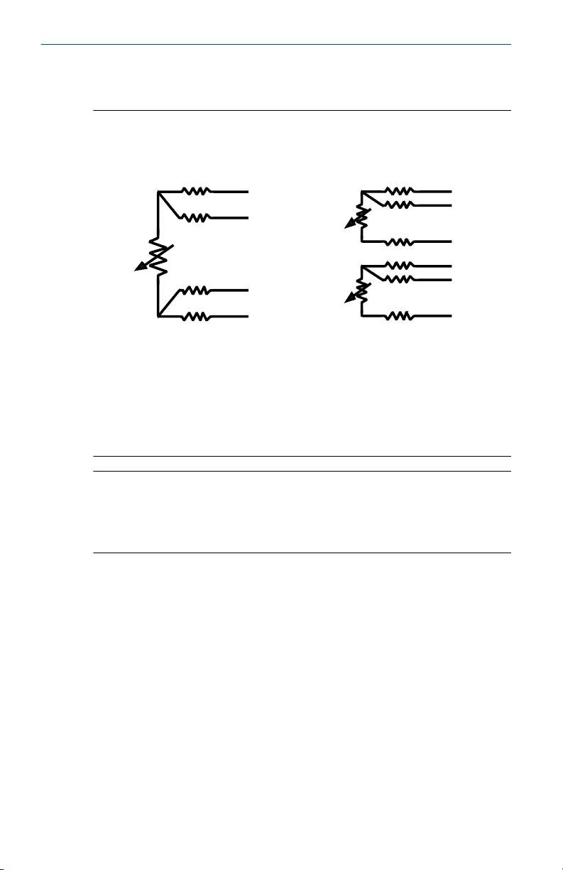
Figure 2-1: Rosemount Series 68, 68Q, 78, and 58C RTD Wire Colors
Single Element Dual Element
(1) Dual element sensors are only available on Rosemount Series 68Q and 78
Sensors.
A. Red
B. White
C. Green
D. Black
(1)
Note
For three-wire systems, use one white and two red leads. Do not connect the
white leads. Insulate or terminate the unused white lead in a manner that
prevents shorting to the ground. For two-wire systems, connect both sets of
leads.
4 Emerson.com/Rosemount
Page 5

+ A
- B
+ C
- B
+ D
- B
+ E
- B
March 2021 Quick Start Guide
Figure 2-2: Rosemount Series 183 Thermocouple Wire Colors
Type J Type E
Type K Type T
A. White
B. Red
C. Purple
D. Yellow
E. Blue
Note
To distinguish the two sensors in dual Rosemount 183 Sensors, there is an
outer insulation wrapped around each pair of sensor wires.
Quick Start Guide 5
Page 6

Quick Start Guide March 2021
3 Rosemount Series 58C sheath cutting
Procedure
1. Determine the length to which the sheath will be cut. The finished
length needs to include an additional 1.5-in. (3.8 cm) for
compression fittings or 2.5-in. (6.5 cm) for spring-loaded fittings (see
Figure 4-1).
2. Remove and save the heat shrink tubing from the rear of the sensor.
3. Place the sensor in a vise, taking care not to overtighten, and position
the tubing cutter on the sheath.
4. Score the sheath to a depth of approximately 1/64-in. (0.4 cm) To
prevent damage to the lead wire insulation, do not cut completely
through the sheath.
5. Firmly grasp the end of the sheath with your hand or a pair of pliers.
Using a sharp snapping motion, break off and remove the excess
sheath material. Take care not to strip or damage the lead wire
insulation while removing the excess sheath material.
Note
If you are unable to easily break off excess sheath material, deepen
the score and repeat Step 5.
6. Replace the heat shrink tubing.
6 Emerson.com/Rosemount
Page 7
A
B
C
D
E
F
March 2021 Quick Start Guide
4 Drawings
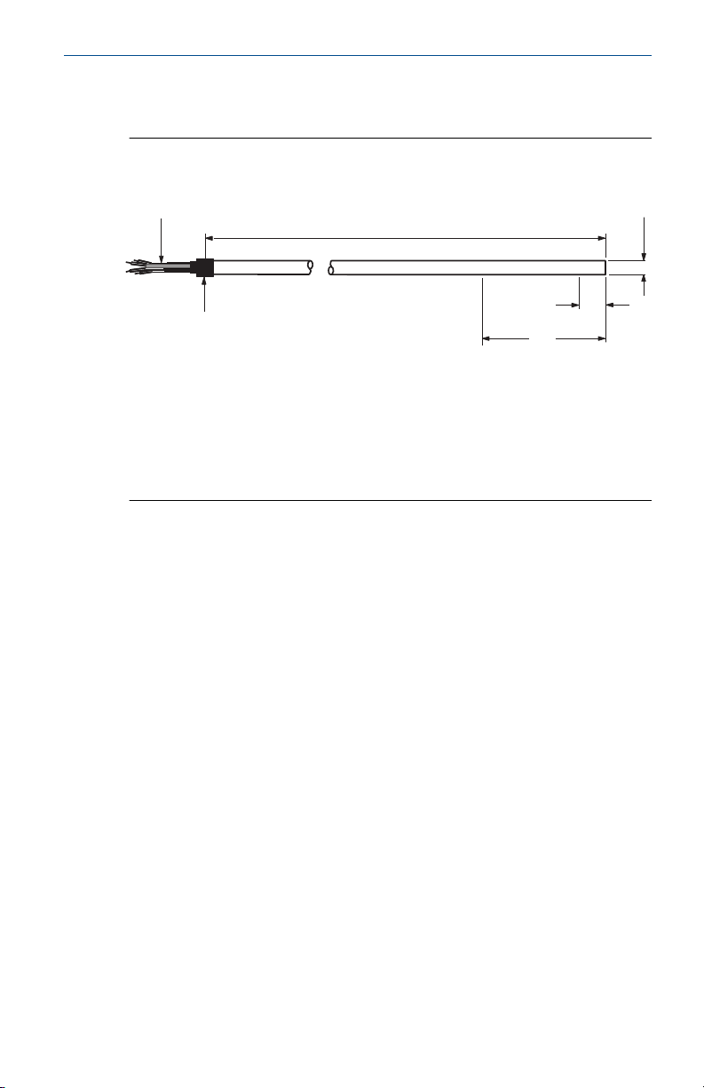
Figure 4-1: Rosemount Series 58C Sensor
A. Four lead wires 6-in. (152 mm) long.
B. X length ±0.25 (±6)
C. 0.25 ±0.002 (6.35 ±0.13) diameter
D. Heat shrink tubing
E. Do not cut or bend sheath within 2-in. (51 mm)
F. 0.6-in. (15 mm) max. sensing element
Quick Start Guide 7
Page 8
A
B
D
C
E
F
I
G
H
K
J
L
M
O
N
P
Q
R
S
T
Quick Start Guide March 2021
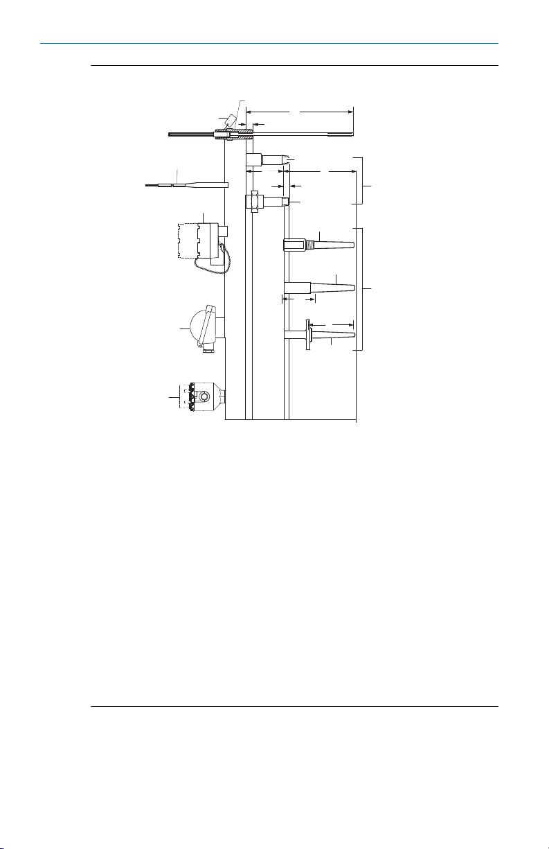
Figure 4-2: Sensor Assembly
A
Open identification tag
B
Standard adapter sensor assembly
C
Sensor immersion length “X”
D
0.5-in. (13 mm) nominal
engagement
E
F
G
H
I
J
8 Emerson.com/Rosemount
Coupling nipple
Extension length
Overall thermowell length
Lead wire extensions and seals
0.5-in. (13 mm) nominal
engagement
Extensions
K
Union nipple
L
Flat or extended cover aluminum
connection heads
M
Threaded thermowell
N
Thermowells
O
T + 1.75-in. (44.5 mm)
P
Socket weld thermowell
Q
Polypropylene connection head
R
Thermowell immersion length
S
Flanged thermowell
T
Rosemount aluminum connection
head
Page 9

March 2021 Quick Start Guide
Note
Sensor assemblies can be provided without an enclosure or with an
enclosure such as the connection heads shown above or assembled to a
Rosemount transmitter.
Quick Start Guide 9
Page 10

Quick Start Guide March 2021
5 Rosemount Series 68 Platinum RTD
5.1 Specifications
5.1.1 Performance specifications
Temperature range
–50 to 400 °C (–58 to 752 °F)
Effect of temperature cycling
±0.05 percent (0.13 °C or 0.23 °F) maximum ice-point resistance shift
following 10 cycles over the specified temperature range
Stability
±0.11 percent 0.28 °C or 0.51 °F maximum ice-point resistance shift
following 1,000 hours at maximum specified temperature (400 °C)
Maximum hysteresis
±0.1 percent of operating temperature range
Time constant
12 seconds maximum required to reach 63.2 percent sensor response in
water flowing at 3 ft/s (0.91 m/s)
Nominal R0 100 Ohm
Nominal alpha 0.00385 Ω/Ω °C
5.1.2 Physical specifications
Material selection
Emerson provides a variety of Rosemount product with various product
options and configurations including materials of construction that can be
expected to perform well in a wide range of applications. The Rosemount
product information presented is intended as a guide for the purchaser to
make an appropriate selection for the application. It is the purchaser’s sole
responsibility to make a careful analysis of all process parameters (such as all
chemical components, temperature, pressure, flow rate, abrasives,
contaminants, etc.), when specifying product, materials, options and
components for the particular application. Emerson is not in a position to
evaluate or guarantee the compatibility of the process fluid or other process
parameters with the product, options, configuration or materials of
construction selected.
Sheath material
316 SST and 321 SST
10 Emerson.com/Rosemount
Page 11

March 2021 Quick Start Guide
Lead wire
PTFE-insulated, silver plated, 24-gauge stranded copper wire
Identification data
The model, serial numbers, and up to six lines of permanent tagging
information are etched on each sensor adapter. Stainless steel tags are
available upon request.
5.1.3 Environmental specifications
Humidity limits
Lead seal can withstand 100 percent relative humidity
Vibration limits
±0.05 percent maximum ice-point resistance shift due to 30 minutes of 14 g
peak vibration from 5 to 350 Hz at 20 °C (68 °F) for unsupported stem length
of less than 6-in.
Quality assurance
Each sensor is subjected to a resistance accuracy test at 0 °C and an
insulation resistance test
Enclosure ratings
When installed properly, Rosemount Series 68 Sensors are suitable for
indoor and outdoor NEMA® 4X and CSA Enclosure Type 4X installations.
Insulation resistance
1000 × 106 ohms minimum insulation resistance when measured at 500 Vdc
at room temperature
5.1.4 Functional specifications
Power
Environmental
Quick Start Guide 11
Overvoltage Category I
Pollution Degree 4
Page 12
Quick Start Guide March 2021
6 Rosemount Series 78 Platinum RTD
6.1 Specifications
6.1.1 Performance specifications
Temperature range
Rosemount Series 78 single- and dual-element sensors may be used in
temperatures from –200 to 500 °C (–328 to 932 °F).
Effect of temperature cycling
±0.04 percent (0.10 °C or 0.18 °F) maximum ice-point resistance shift
following 10 cycles between –200 and 500 °C (–328 to 932 °F).
Stability
±0.05 percent maximum ice-point resistance shift following 1,000 hours at
400 °C (752 °F).
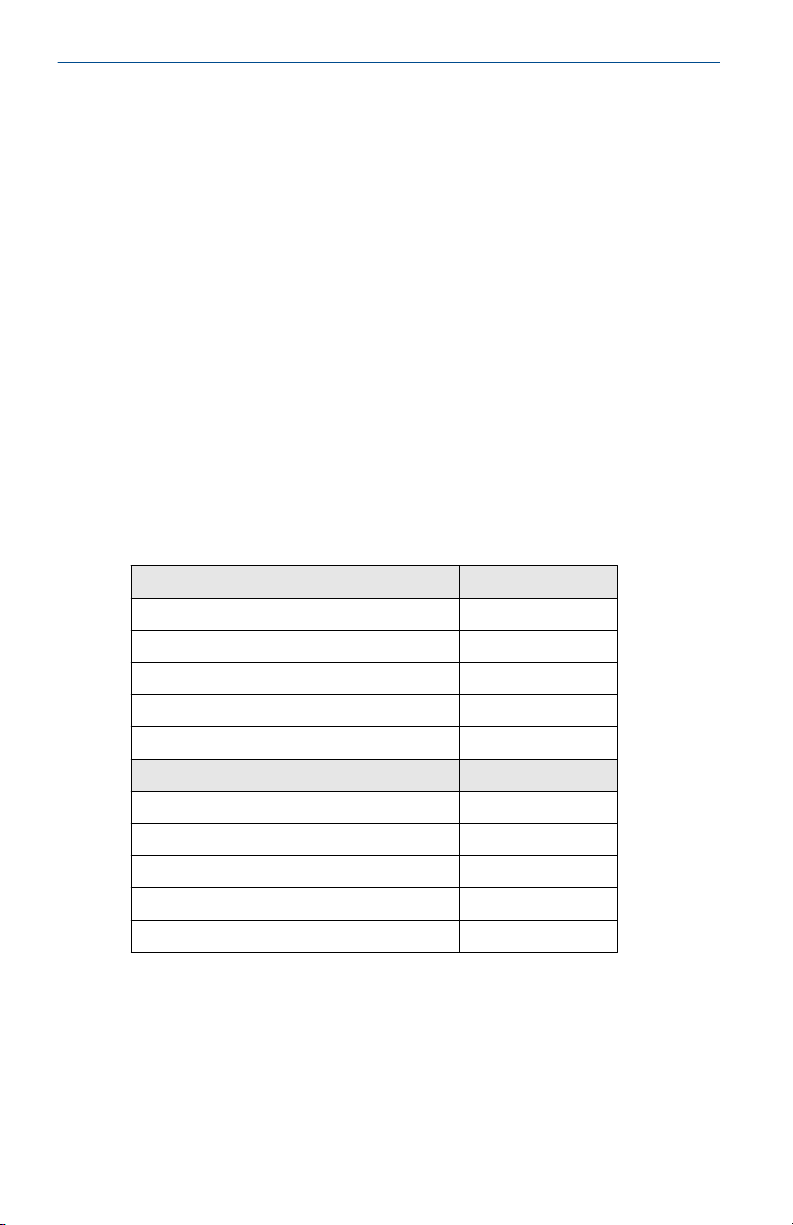
Table 6-1: Rosemount Series 78 Interchangeability
Both tolerances valid from –200 to 500 °C.
Standard series 78 IEC-751 Class B Temperature
±0.80 °C (±1.44 °F) –100 °C (–148 °F)
±0.30 °C (±0.54 °F) 0 °C (32 °F)
±0.80 °C (±1.44 °F) 100 °C (212 °F)
±1.80 °C (±3.24 °F) 300 °C (572 °F)
±2.30 °C (±4.14 °F) 400 °C (752 °F)
Series 78 with IEC-751 Class A option Temperature
±0.35 °C (±0.63 °F) –100 °C (–148 °F)
±0.15 °C (±0.27 °F) 0 °C (32 °F)
±0.35 °C (±0.63 °F) 100 °C (212 °F)
±0.75 °C (±1.35 °F) 300 °C (572 °F)
±0.95 °C (±1.71 °F) 400 °C (752 °F)
Maximum hysteresis
Single- and dual-element, Nominal R0 100 Ohm Nominal alpha 0.00385 Ω/
Ω °C: ±0.04 percent of range
12 Emerson.com/Rosemount
Page 13

March 2021 Quick Start Guide
Time constant
4 seconds maximum required to reach 63.2 percent sensor response in
water flowing at 3 ft/s (0.91 m/s).
Self heating
18 mW minimum power dissipation required to cause a 1 °C (1.8 °F)
temperature measurement error in water flowing at 3 ft/s.
Insulation resistance
500 × 106 ohms minimum insulation resistance when measured at 500 Vdc
at room temperature (20 °C [68 °F]).
6.1.2 Environmental specifications
Humidity limits
Lead seal is capable of withstanding 100 percent relative humidity.
Vibration limits
Standard single- and dual-element sensors
±0.03 percent maximum ice-point resistance shift due to 30 minutes of 21 g
peak vibration from 5 to 350 Hz continuous sweep at 20 °C (68 °F) for
unsupported stem length of less than 5.5-in. (140 mm).
Quality assurance
Each sensor is subjected to a resistance accuracy test at 0 °C and an
insulation resistance test.
Enclosure ratings
When installed properly, Rosemount Series 78 Sensors are suitable for
indoor and outdoor NEMA 4X and CSA Enclosure Type 4X installations.
6.1.3 Physical specifications
Sheath material
Single and dual-element, 316 SST
Lead wires
Single and dual-element, PTFE-insulated, nickel-coated, 22-gauge stranded
copper wire.
Identification data
The model and serial numbers and up to six lines of permanent tagging
information are etched on each sensor adapter. Stainless steel tags are
available upon request.
Quick Start Guide 13
Page 14

Quick Start Guide March 2021
6.1.4 Functional specifications
Power
Environmental
Overvoltage Category I
Pollution Degree 4
14 Emerson.com/Rosemount
Page 15

March 2021 Quick Start Guide
7 Rosemount Series 183 Thermocouple
7.1 Specifications
7.1.1 Performance Specifications
The thermoelectric current relationship in a thermocouple is standardized
and defined by ASTM E-230. All Rosemount Series 183 Thermocouples
conform to these standards with “special limits of error” accuracy. The
particular characteristics of each ISA type thermocouple are outlined in
Table 7-1.
7.1.2 Physical specifications
Sheath material
304 SST for types J, E, and T (used at temperatures up to 871 °C). Inconel for
type K (used at temperatures up to 1150 °C).
Lead wires
Thermocouple, external lead wires—20 AWG wire, PTFE-insulated. Color
coded per lead wire configuration schematic shown in Figure 2-2.
Identification data
The model and serial numbers and up to six lines of permanent tagging
information are etched on each sensor adapter. Stainless steel tags are
available upon request.
Insulation resistance
100 × 106 ohms minimum insulation resistance when measured at 100 Vdc
at room temperature.
Enclosure ratings
When installed properly, Rosemount Series 183 Sensors are suitable for
indoor and outdoor NEMA 4X and installations.
Quick Start Guide 15
Page 16
32 1000 2000
Degrees Farenheit
0
20
40
60
80
Millivolts (approx.)
Type E
Type J
Type T
Type K
Type K
Quick Start Guide March 2021
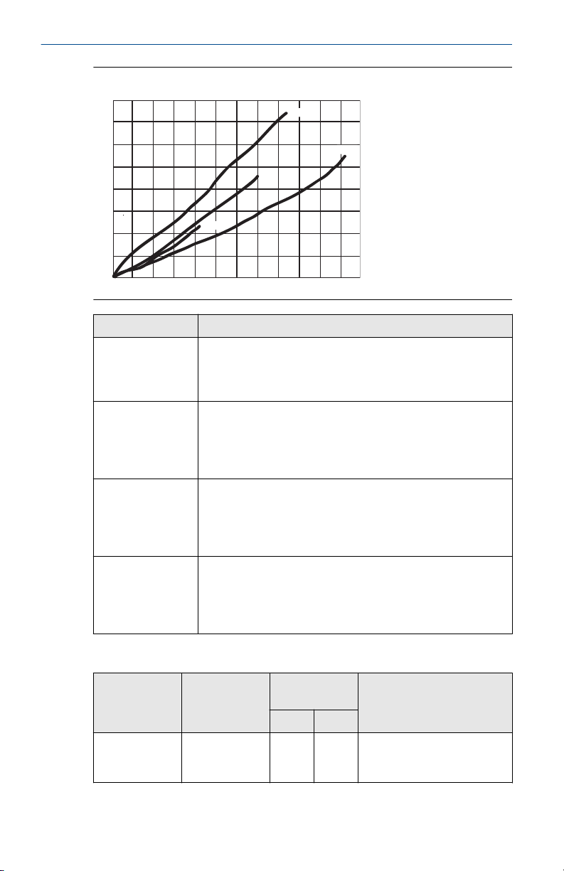
Figure 7-1: Comparison of Thermocouples
Thermocouple Conditions for use
Type J Iron/
Constantan
Type K Chromel/
Alumel
Type E Chromel/
Constantan
Type T Copper/
Constantan
Maximum operating temperature of 760 °C (1400 °F). Used
with or without protective tubing where deficiency of free
oxygen exists. Protective tube not essential, but desirable for
cleanliness and longer service.
Suitable for extended use in temperatures reaching 1150 °C
(2102 °F). Use of metal or ceramic protective tube desirable,
especially in reducing atmospheres. In oxidizing atmospheres,
protective tubing necessary only to promote cleanliness and
longer service.
Suitable for use at temperature up to 871 °C (1600 °F) in
vacuum or inert, mildly oxidizing, or reducing atmosphere.
Not subject to corrosion at cryogenic temperatures. Has
highest EMF output per degree of all commonly used
thermocouples.
Operating temperature range of –180 to 371 °C (–292 to 700
°F). Use in either oxidizing or reducing atmospheres.
Protective tubing necessary only to promote cleanliness and
longer service. Stable at lower temperature. Superior for a
wide variety of uses in cryogenic temperatures.
ISA
thermocouple
types
J Iron/
16 Emerson.com/Rosemount
Thermocouple
wire alloys
Constantan
Temperature
range
°C °F
0 to
32 to
760
1400
Limits of error
(interchangeability)
±1.1 °C (2.0 °F) or ±0.4% of
measured temperature,
whichever is greater
Table 7-1: Characteristics of Series 183 Thermocouple Types
Page 17

March 2021 Quick Start Guide
Table 7-1: Characteristics of Series 183 Thermocouple Types (continued)
ISA
thermocouple
types
K Chromel/
E Chromel/
T Copper/
Thermocouple
wire alloys
Alumel
Constantan
Constantan
7.1.3 Functional specifications
Power
Environmental
Temperature
range
°C °F
0 to
1150
0 to
871
–180
to 0
0 to
371
Limits of error
(interchangeability)
32 to
±1.1 °C (2.0 °F) or ±0.4% of
2102
measured temperature,
whichever is greater
32 to
±1.0 °C (1.8 °F) or ±0.4% of
1600
measured temperature,
whichever is greater
–292
±1.0 °C (1.8 °F) or ±1.5% of
to 32
measured temperature,
whichever is greater
32 to
±0.5 °C (1.0 °F) or ±0.4% of
700
measured temperature,
whichever is greater
Overvoltage Category I
Pollution Degree 4
Quick Start Guide 17
Page 18

Quick Start Guide March 2021
8 Rosemount Series 68Q Sanitary Platinum RTD
8.1 Specifications
8.1.1 Performance specifications
Temperature range
–50 to 200 °C (–58 to 392 °F)
Maximum hysteresis
±0.09 percent of operating temperature range
Stability
Tri Clamp O.D. tube size 1-in. and greater
±0.04 percent maximum ice-point resistance shift following 1,000 hours at
maximum specified temperature 392 °F (200 °C)
Tri Clamp O.D. tube size ½- to ¾-in.
±0.08 percent maximum ice-point resistance shift following 1,000 hours at
maximum specified temperature 392 °F (200 °C)
Response time
Tri Clamp O.D. tube size 1-in. and greater
Less than 3.5 seconds required to reach 63.2 percent sensor response in
water flowing at 3 ft/s (0.91 m/s). Meets PMO specification.
Tri Clamp O.D. tube size ½- to ¾-in.
Less than 1.5 seconds required to reach 63.2 percent sensor response in
water flowing at 3 ft/s (0.91 m/s).
Insulation Resistance
500 × 106 ohms minimum insulation resistance when measured at 100 Vdc
at room temperature
Surface Finish
32RA standard finish on product contact surfaces. Meets 3A requirements.
15RA high mechanical polish available with option code HP.
8.1.2 Environmental specifications
Humidity limits
Lead seal is capable of withstanding 100 percent relative humidity.
18 Emerson.com/Rosemount
Page 19

March 2021 Quick Start Guide
Quality assurance
Each sensor is subjected to a resistance accuracy test at 0 °C.
8.1.3 Physical specifications
Sheath material
316L SST
Lead wire
PTFE-insulated, nickel-coated, 24-gauge stranded copper wire
Identification data
The model and serial numbers and up to six lines of permanent tagging
information are etched on each sensor adapter. Stainless steel tags are
available upon request.
8.1.4 Functional specifications
Power
Environmental
Overvoltage Category I
Pollution Degree 4
Quick Start Guide 19
Page 20

Quick Start Guide March 2021
9 Rosemount Series 58C Platinum RTD
9.1 Specifications
9.1.1 Performance specifications
Temperature range
–50 to 200 °C (–58 to 392 °F)
Maximum hysteresis
±0.09 percent of operating temperature range
Stability
±0.035 percent maximum ice-point resistance shift following 1,000 hours at
maximum specified temperature 200 °C (392 °F)
Insulation resistance
500 x106 ohms minimum insulation resistance when measured at 50 Vdc at
room temperature
9.1.2 Environmental specifications
Humidity limits
No permanent rear seal is installed.
Quality assurance
Each sensor is subjected to a resistance accuracy test at 0 °C (32 °F) and an
insulation resistance test.
9.1.3 Physical specifications
Sheath material
316 SST
Lead wires
PTFE-insulated, nickel-coated, 24-gauge stranded copper wire
9.1.4 Functional specifications
Power
Environmental
20 Emerson.com/Rosemount
Overvoltage Category I
Pollution Degree 4
Page 21

March 2021 Quick Start Guide
10 Product certifications
Rev 2.21
10.1 European Directive Information
A copy of the EC Declaration of Conformity can be found at the end of the
Quick Start Guide. The most recent revision of the EC Declaration of
Conformity can be found at Emerson.com/Rosemount.
10.2 Ordinary Location Certification
As standard, the transmitter has been examined and tested to determine
that the design meets the basic electrical, mechanical, and fire protection
requirements by a nationally recognized test laboratory (NRTL) as accredited
by the Federal Occupational Safety and Health Administration (OSHA).
Note
The terminal strip in the Aluminum Connection Head with Six Terminals (R,
T, P or L) requires sensor lead wires to have a wire termination (Ex: Bootlace
ferrule or spade lug).
10.3 North America
The US National Electrical Code (NEC) and the Canadian Electrical Code
(CEC) permit the use of Division marked equipment in Zones and Zone
marked equipment in Divisions. The markings must be suitable for the area
classification, gas, and temperature class. This information is clearly defined
in the respective codes.
10.4
USA
E5 FM Explosion proof, Dust-Ignition proof
Certificate
Standards
Markings
FM17US0170X
FM Class 3600: 2011; FM Class 3611: 2004; FM Class 3615:
2006; FM Class 3810: 2005; ANSI/NEMA - 250: 1991
XP CL I, Div 1, GP B, C, D; DIP CL II/III, Div 1, GP E, F, G; T5(-50
°C ≤ Ta ≤ 85 °C); when installed per Rosemount drawing
00068-0013; Type 4X
10.5 Canada
E6 CSA Explosion proof and Dust-Ignition proof
Certificate
Quick Start Guide 21
70044744
Page 22

Quick Start Guide March 2021
Standards
Markings
†
Spring loaded indicator has reduced ingress and dust ratings. Spring loaded
sensors must be installed in a thermowell to maintain dust and ingress
ratings. Un-painted aluminum enclosures are Type 4 rated.
*Assembly is not Canada Explosionproof (E6) rated to Group B if the R, T, P
or L (Aluminum Connection Head with Six Terminals) connection head is
used
10.6 Europe
E1 ATEX Flameproof
Certificate
Standards
Markings
CAN/CSA C22.2 No. 0:2010, CAN/CSA No. 25-1966 (R2000),
CAN/CSA C22.2 No. 30-M1986 (R2012), CAN/CSA C22.2 No.
94-M1991 (R2011)
XP CL I, DIV 1, GP B*, C, D; DIP CL II, DIV 1, GP E, F, G; CL III; T6
(-50 °C ≤ Ta ≤ +80 °C), T5 (-50 °C ≤ Ta ≤ +95 °C); Seal not
required; installed per Rosemount drawing 00068-0033; Type
4X† and IP 66/67; V
35 VDC, 750 mW
max
max
FM12ATEX0065X
EN 60079-0: 2012+A11:2013, EN 60079-1: 2014, EN
60529:1991 +A1:2000 + A2:2013
II 2 G Ex db IIC T6…T1 Gb, T6(-50 °C ≤ Ta ≤ +40 °C), T5…
T1(-50 °C ≤ Ta ≤ +60 °C)
See Process temperature limits for process temperatures.
Special Conditions for Safe Use(X):
1. See certificate for ambient temperature range.
2. The non-metallic label may store an electrostatic charge and become
a source of ignition in Group III environments.
3. Guard the LCD display cover against impact energies greater than 4
joules.
4. Flameproof joints are not intended for repair.
5. A suitable certified Ex d or Ex tb enclosure is required to be connected
to temperature probes with Enclosure option “N”.
6. Care shall be taken by the end user to ensure that the external
surface temperature on the equipment and the neck of DIN Style
Sensor probe does not exceed 130 °C.
7. Non-Standard Paint options may cause risk from electrostatic
discharge. Avoid installations that cause electrostatic build-up on
painted surfaces, and only clean the painted surfaces with a damp
22 Emerson.com/Rosemount
Page 23

March 2021 Quick Start Guide
cloth. If paint is ordered through a special option code, contact the
manufacturer for more information.
10.7 International
E7 IECEx Flameproof
Certificate
Standards
Markings
Special Conditions for Safe Use(X):
1. See certificate for ambient temperature range.
2. The non-metallic label may store an electrostatic charge and become
3. Guard the LCD display cover against impact energies greater than 4
4. Flameproof joints are not intended for repair.
5. A suitable certified Ex d or Ex tb enclosure is required to be connected
6. Care shall be taken by the end user to ensure that the external
7. Non-Standard Paint options may cause risk from electrostatic
IECEx FMG 12.0022X
IEC 60079-0:2011, IEC 60079-1:2014-06
Ex db IIC T6…T1 Gb, T6(-50 °C ≤ Ta ≤ +40 °C), T5…T1(-50 °C ≤
Ta ≤ +60 °C)
See Process temperature limits for process temperatures.
a source of ignition in Group III environments.
joules.
to temperature probes with Enclosure option “N”.
surface temperature on the equipment and the neck of DIN Style
Sensor probe does not exceed 130 °C.
discharge. Avoid installations that cause electrostatic build-up on
painted surfaces, and only clean the painted surfaces with a damp
cloth. If paint is ordered through a special option code, contact the
manufacturer for more information.
NK IECEx Dust-Ignitionproof
Certificate
Standards
Markings
Special Conditions for Safe Use(X):
1. See certificate for ambient temperature range.
Quick Start Guide 23
IECEx FMG 12.0022X
IEC 60079-0:2011, IEC 60079-1:2013
Ex tb IIIC T130 °C Db Ta = -40 °C to +70 °C; IP66
See Process temperature limits for process temperatures.
Page 24

Quick Start Guide March 2021
2. The non-metallic label may store an electrostatic charge and become
a source of ignition in Group III environments
3. Guard the LCD display cover against impact energies greater than 4
joules.
4. Flameproof joints are not intended for repair
5. A suitable certified Ex db or Ex tb enclosure is required to be
connected to temperature probes with Enclosure option "N".
6. Care shall be taken by the end user to ensure that the external
surface temperature on the equipment and the neck of DIN Style
Sensor probe does not exceed 130 °C.
7. Non-Standard Paint options may cause risk from electrostatic
discharge. Avoid installations that cause electrostatic build-up on
painted surfaces, and only clean the painted surfaces with a damp
cloth. If paint is ordered through a special option code, contact the
manufacturer for more information.
10.8 Brazil
E2 INMETRO Flameproof
Certificate
Standards
Markings
Special Conditions for Safe Use (X):
1. See certificate for ambient temperature range.
2. The non-metallic label may store an electrostatic charge and become
3. Guard the LCD display cover against impact energies greater than 4
4. A suitable certified Ex d or Ex tb enclosure is required to be connected
5. Care shall be taken by the end user to ensure that the external
6. Consult the manufacturer if dimensional information on the
UL-BR 13.0535X
ABNT NBR IEC 60079-0:2013; ABNT NBR IEC 60079-1:2016;
ABNT NBR IEC 60079-31:2014
Ex db IIC T6…T1 Gb T6…T1(-50 °C ≤ Ta ≤ +40 °C), T5…T1(-50
°C ≤ Ta ≤ +60 °C)
Ex tb IIIC T130 °C Db (-40 °C ≤ Ta ≤ +70 °C)
a source of ignition in Group III environments.
joules.
to temperature probes with Enclosure option "N".
surface temperature on the equipment and the neck of DIN Style
Sensor probe does not exceed 130 °C.
flameproof joints is necessary.
24 Emerson.com/Rosemount
Page 25
March 2021 Quick Start Guide
10.9 EAC
EM Technical Regulations Customs Union (EAC) Flameproof
Markings
Special Condition for Safe Use(X):
See certificate.
1Ex db IIC T6…T1 Gb X; T6 (-55 to 40 °C); T5..T1 (-55 to 60 °C);
IP66, IP68
10.10 Korea
EP Korea Explosionproof/Flameproof
Certificate
Markings
Special Condition for Safe Use(X):
See certificate.
13-KB4BO-0560X
Ex d IIC T6…T1; T6(–50 °C ≤ Ta ≤ +40 °C), T5…T1(–50 °C ≤ Ta ≤
+60 °C)
10.11 Combinations
KF
KD
Combination of E1 and E6
Combination of E5, E6, and E1
10.12 Process temperature limits
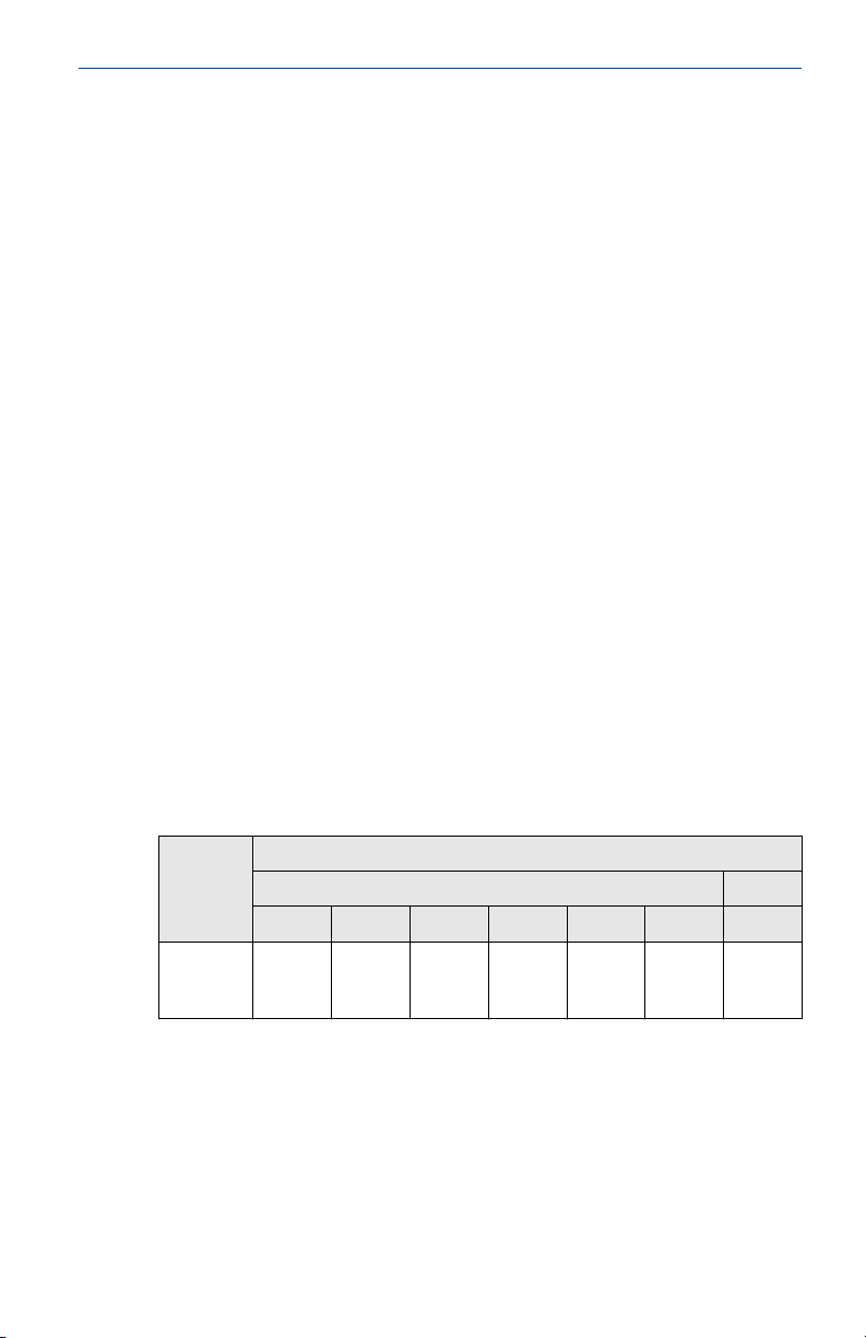
Table 10-1: Sensor Only (No Transmitter Installed)
Process temperature (°C)
Extension
length
T6 T5 T4 T3 T2 T1 T130 °C
Any
extension
length
Quick Start Guide 25
85 100 135 200 300 450 130
Gas Dust
Page 26
Quick Start Guide March 2021
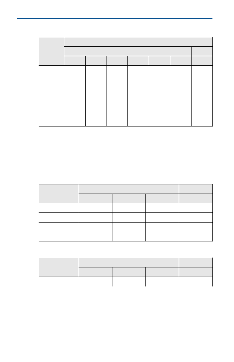
Table 10-2: Transmitter
Process temperature (°C)
Extension
length
No
extention
3-in.
extension
6-in.
extension
9-in
extension
T6 T5 T4 T3 T2 T1 T130 °C
55 70 100 170 280 440 100
55 70 110 190 300 450 110
60 70 120 200 300 450 110
65 75 130 200 300 450 120
Gas Dust
Adhering to the process temperature limitations of Table 10-3 will ensure
that the service temperature limitations of the LCD cover are not exceeded.
Process temperatures may exceed the limits defined in Table 10-3 if the
temperature of the LCD cover is verified to not exceed the service
temperatures in Table 10-4 and the process temperatures do not exceed the
values specified in Table 10-2.
Table 10-3: Transmitter with LCD Cover - Process Temperature (°C)
Extension length
T6 T5 T4...T1 T130 °C
No extension 55 70 95 95
3-in. extension 55 70 100 100
6-in. extension 60 70 100 100
9-in. extension 65 75 110 110
Gas Dust
Table 10-4: Transmitter with LCD Cover - Service Temperature (°C)
Extension length
T6 T5 T4...T1 T130 °C
No extension 65 75 95 95
26 Emerson.com/Rosemount
Gas Dust
Page 27
March 2021 Quick Start Guide
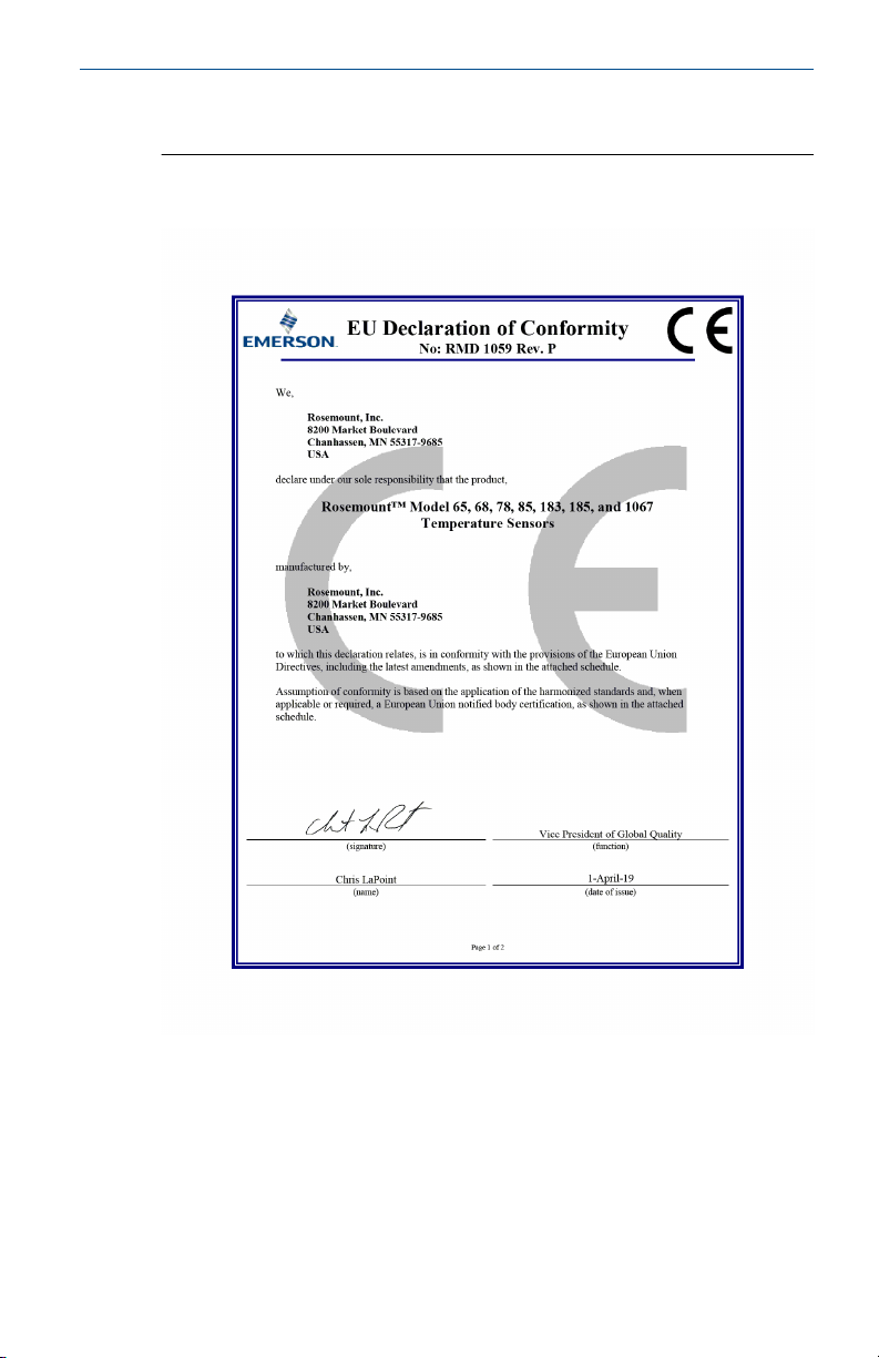
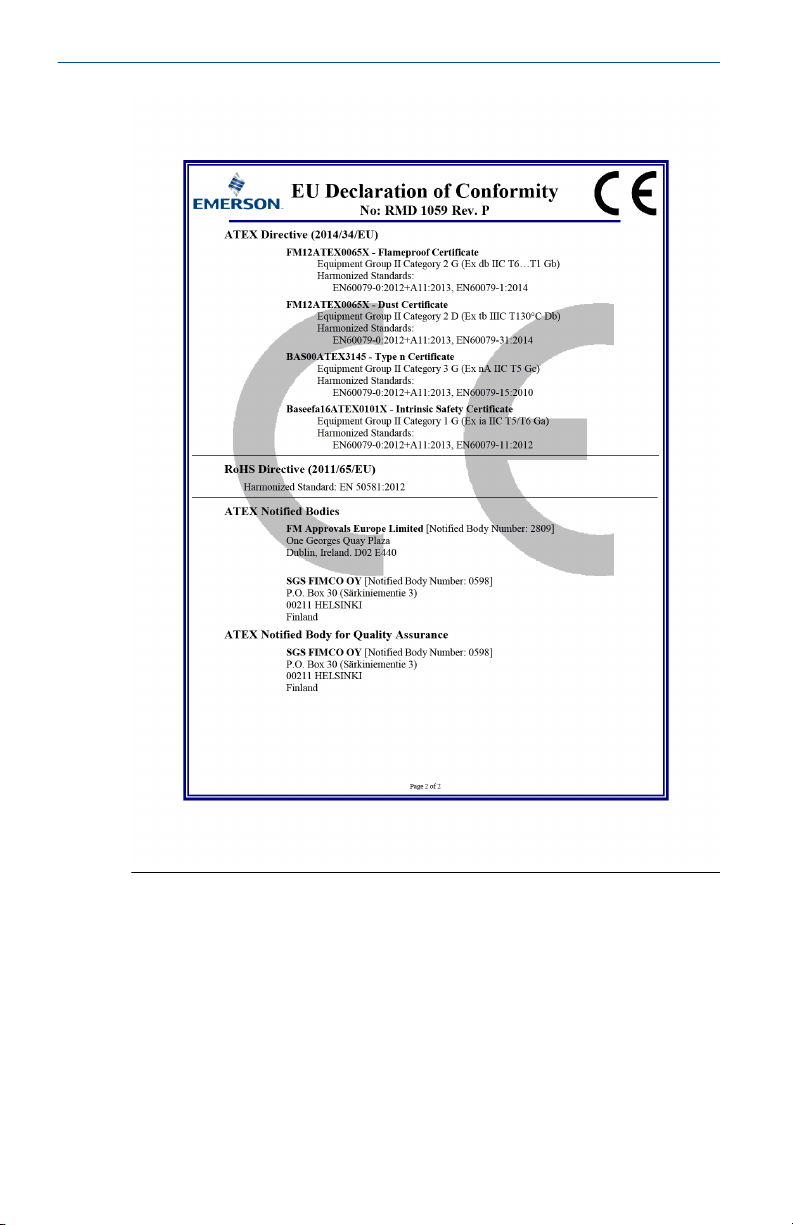
10.13 Declaration of Conformity
Figure 10-1: Rosemount Series 68, 78, and 183 Declaration of
Conformity
Quick Start Guide 27
Page 28
Quick Start Guide March 2021
28 Emerson.com/Rosemount
Page 29
0068, 0078 and 0183
2/9/2 021
ᴹ
China RoHS
㇑᧗⢙䍘䎵䗷ᴰབྷ⎃ᓖ䲀٬Ⲵ䜘Ԧරࡇ㺘
0068, 0078 and 0183 Temperature
Sensors
List of 0068, 0078 and 0183 Temperature Sensor Parts with China RoHS Concentration above MCVs
䜘Ԧ〠
Part Name
ᴹᇣ⢙䍘/ Hazardous Substances
䫵
Lead
(Pb)
⊎
Mercury
(Hg)
䭹
Cadmium
(Cd)
ޝԧ䬜
Hexavalent
Chromium
(Cr +6)
ཊⓤ㚄㤟
Polybrominated
biphenyls
(PBB)
ཊⓤ㚄㤟䟊
Polybrominated
diphenyl ethers
(PBDE)
༣փ㓴Ԧ
Housing
Assembly
O O O O O
O
Րᝏಘ㓴Ԧ
Sensor
Assembly
O O O O O
O
ᵜ㺘Ṭ㌫ᦞ
SJ/T11364
Ⲵ㿴ᇊ㘼ࡦ
This table is pr oposed in accordance with the provision of SJ/T11364.
O:
Ѫ䈕䜘ԦⲴᡰᴹ൷䍘ᶀᯉѝ䈕ᴹᇣ⢙䍘Ⲵ䟿൷վҾ
GB/T 26572
ᡰ㿴ᇊⲴ䲀䟿㾱≲
O: Indicate that said hazardous substance in all of the homogeneous materials for this part is below the limit
requirement of GB/T 26572.
X:
Ѫ൘䈕䜘Ԧᡰ֯⭘Ⲵᡰᴹ൷䍘ᶀᯉ䟼ˈ㠣ቁᴹа㊫൷䍘ᶀᯉѝ䈕ᴹᇣ⢙䍘Ⲵ䟿儈Ҿ
G B/T 26572
ᡰ㿴ᇊⲴ䲀䟿㾱≲
X: Indicate that said hazardous substance contained in at least one of the homogeneous materials used for this part is
above the limit requirement of GB/T 26572.
䜘Ԧ〠
Part Name
㓴㻵༷Ԧ䈤᰾
Spare Parts Descriptions for Assemblies
༣փ㓴Ԧ
Housing
Assembly
⭥ᆀཆ༣ Electrical Housing
March 2021 Quick Start Guide
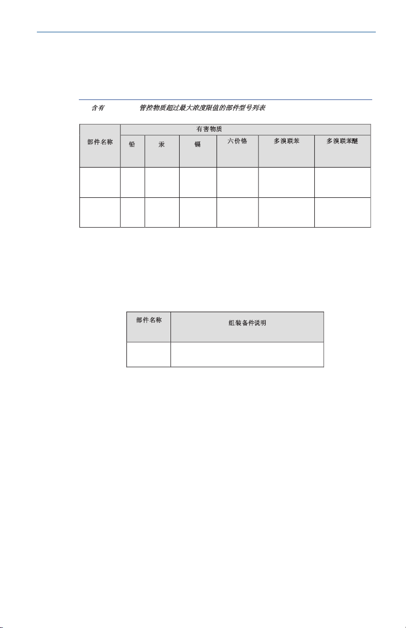
10.14 China RoHS
Quick Start Guide 29
Page 30

Quick Start Guide March 2021
30 Emerson.com/Rosemount
Page 31

March 2021 Quick Start Guide
Quick Start Guide 31
Page 32

*00825-0300-2654*
00825-0300-2654, Rev. GB
Quick Start Guide
March 2021
©
2021 Emerson. All rights reserved.
Emerson Terms and Conditions of Sale are
available upon request. The Emerson logo
is a trademark and service mark of
Emerson Electric Co. Rosemount is a mark
of one of the Emerson family of
companies. All other marks are the
property of their respective owners.
 Loading...