

World Class 3000 O2 Analyzer with CRE 3000 Control Room Electronics-Rev 4.4
Table of contents
 Loading...
Rosemount World Class 3000 O2 Analyzer with CRE 3000 Control Room Electronics-Rev 4.4 Manuals & Guides

Instruction Manual
IB-106-300NC Rev. 4.4
February 1998
World Class 3000
Oxygen Analyzer with CRE 3000
Control Room Electronics
http://www.processanalytic.com

ESSENTIAL INSTRUCTIONS
READ THIS PAGE BEFORE PROCEEDING!
Rosemount Analytical designs, manufactures and tests its products to meet many national and
international standards. Because these instruments are sophisticated technical products, you
MUST properly install, use, and maintain them to ensure they continue to operate within their
normal specifications. The following instructions MUST be adhered to and integrated into your
safety program when installing, using, and maintaining Rosemount Analytical products. Failure to
follow the proper instructions may cause any one of the following situations to occur: Loss of life;
personal injury; property damage; damage to this instrument; and warranty invalidation.
• Read all instructions prior to installing, operating, and servicing the product.
• If you do not understand any of the instructions, contact your Rosemount Analytical repre-
sentative for clarification.
• Follow all warnings, cautions, and instructions marked on and supplied with the product.
• Inform and educate your personnel in the proper installation, operation, and mainte-
nance of the product.
• Install your equipment as specified in the Installation Instructions of the appropriate In-
struction Manual and per applicable local and national codes. Connect all products to the
proper electrical and pressure sources.
• To ensure proper performance, use qualified personnel to install, operate, update, program,
and maintain the product.
• When replacement parts are required, ensure that qualified people use replacement parts
specified by Rosemount. Unauthorized parts and procedures can affect the product’s performance, place the safe operation of your process at risk, and VOID YOUR WARRANTY.
Look-alike substitutions may result in fire, electrical hazards, or improper operation.
• Ensure that all equipment doors are closed and protective covers are in place, except
when maintenance is being performed by qualified persons, to prevent electrical shock
and personal injury.
The information contained in this document is subject to change without notice.
Emerson Process Management
Rosemount Analytical Inc.
Process Analytic Division
1201 N. Main St.
Orrville, OH 44667-0901
T (330) 682-9010
F (330) 684-4434
e-mail: gas.csc@EmersonProcess.com
http://www.processanalytic.com

HIGHLIGHTS OF CHANGES
Effective October, 1995 Rev. 4
Page Summary
--- General. Updated art to reflect new probe configuration.
Page 2-1 Changed installation procedure to include optional ceramic diffusor
and vee deflector.
Page 3-16 Added manual block valve requirement to required equipment
Effective June, 1996 Rev. 4.1
Page Summary
Page 2-2, 2-3 Updated figure to reflect probe modification.
Page 3-13, 3-15,
3-17
Page Summary
P-2 Added "Safety instructions for the wiring and installation of this
Page 1-6 Added NOTE 8 regarding fuse specifications and changed probe
Page 2-1 Added one WARNING to read new safety instructions and another
Page 2-8 Deleted obsolete paragraphs 2-2b.1 and 2-2b.2.
Page 2-10 Added NOTE regarding reference to Figure 2-6 for CRE unit fuse lo-
Page 2-13 Added NOTE regarding reference to Figure 2-16 for HPS fuse loca-
Page 2-14 Changed probe ground lead color code to GN/YE in Figure 2-13.
Page 2-17 Added NOTE regarding HPS fuse specifications to Figure 2-16.
Page 2-20 Added NOTE regarding reference to Figure 2-19 for MPS fuse loca-
Added note regarding ambient air not recommended for use as high
test gas.
Effective January, 1997 Rev. 4.2
apparatus".
ground lead color code to GN/YE in Figure 1-3.
WARNING regarding protective covers and grounds.
cations and specifications and added NOTE regarding CRE fuse
specifications to Figure 2-6.
tions and specifications.
tions and specifications.
Page 2-20 Added NOTE regarding MPS fuse specifications to Figure 2-19.
Page 4-1 Added WARNING regarding protective covers and grounds.
Page 7-1 Added fuses to index listing.

HIGHLIGHTS OF CHANGES (CONTINUED)
Effective May, 1997 Rev. 4.3
Page Summary
Page P-2 Added safety sheet.
Effective February, 1998 Rev. 4.4
Page Summary
Page 2-2 Figure 2-1. Change calibration gas tube dimensions.
Page 3-15 Add note on test gas flowmeter.

HIGHLIGHTS OF CHANGES
APPENDIX A
Effective May, 1996 Rev. 3
Page Summary
-- General. Updated appendix to reflect probe design changes.
Page A-13 Added “Extended temperature by-pass arrangements” to Figure A-13
(Sheet 3 of 3)
Effective June, 1996 Rev. 3.1
Page Summary
Page A-13 Updated part ordering information.
Effective August, 1996 Rev. 3.2
Page Summary
Page A-25 Updated cell replacement kit part numbers for the probe.
Effective October, 1996 Rev. 3.3
Page Summary
Page A-6 Added NOTE to Figure A-7.
Effective January, 1997 Rev. 3.4
Page Summary
Page A-1 Added warning to read new safety instructions.
Page A-12 Added protective covers and grounds warning.
Page A-16 Added protective covers and grounds warning.
Effective February, 1998 Rev. 3.5
Page Summary
Page A-18 Changed screw torque in paragraph A-11h.
Effective July, 1998 Rev. 3.6
Page Summary
-- Changed test gas to calibration gas and reference gas to reference
air throughout the appendix.

HIGHLIGHTS OF CHANGES
APPENDIX B
Effective February, 1992 Rev. 2
Page Summary
Page B-1 Figure B-1. New HPS 3000 Optional Class 1, Division 1, Group B
(IP56) Explosion-Proof Enclosure added.
Page B-11 Figure and Index No. column added to Table B-2. Replacement Parts
for Heater Power Supply.
Effective January, 1995 Rev. 2.1
Page Summary
Page B-3 Updated Figure B-3, Heater Power Supply Block Diagram for IB
consistency.
Effective January, 1997 Rev. 2.2
Page Summary
Page B-1 Added warning to read new safety instructions.
Page B-3 Corrected Table B-1 specifications list.
Page B-4 Added protective covers and grounds warning.
Page B-8 Added protective covers and grounds warning.
Page B-11 Added expanded fuse description.

HIGHLIGHTS OF CHANGES
APPENDIX C
Effective February, 1992 Rev. 2
Page Summary
Page C-4 Figure C-3. Optional Panel Mounting Kit description added.
Page C-14 Figure and Index No. column added to Table C-2. Replacement Parts
for the Master/Slave CRE 3000 Module.
Effective February, 1995 Rev. 2.1
Page Summary
Page C-5 Updated Figure C-4 for IB consistency.
Effective October, 1995 Rev. 2.2
Page Summary
Page C-5 Updated art to reflect new probe configuration.
Effective January, 1997 Rev. 2.3
Page Summary
Page C-1 Added warning to read new safety instructions.
Page C-6 Added protective covers and grounds warning.
Page C-6 Added reference to Table C-1 for replacement fuse specifications.
Page C-6 Amended Legend for Figure C-5.
Page C-7 Removed obsolete jumper, Item 14 from Figure C-5.
Page C-9 Deleted obsolete paragraph C-6c.
Page C-14 Revised Table C-2 to introduce new power supply and added ex-
panded fuse description.

HIGHLIGHTS OF CHANGES
Effective June, 1994 Rev. 2
Page Summary
APPENDIX D
Page D-1
Page D-2
Page D-3
Page D-4
Page D-7
Page D-8
Page D-10
Page D-11
Page Summary
Page D-1 Updated Figure D-1, MPS 3000 to include hinge.
Page Summary
Page D-11 Updated replacement parts list to reflect new part numbers.
MPS outline drawing changed to show new MPS.
MPS interior view replaced with new MPS in Figure D-2.
"Optional" for check valve deleted in Figure D-3.
Drawing showing location of optional Z-Purge added as Figure D-4.
Power supply replacement procedures in paragraph D-7 changed to
reflect new design in the MPS. Solenoid valve replacement procedures in paragraph D-8 changed to reflect new design in the MPS.
Old exploded view of MPS replaced with new MPS.
Paragraph D-11, Adding Probes to the new MPS, added.
Change part numbers for the power supply, solenoid valve, and test
gas flowmeter assembly. Add part numbers for reference gas flowmeter assembly and all the parts in the probe adder kit.
Effective January, 1995 Rev. 2.1
Effective May, 1996 Rev. 2.2
Effective January, 1997 Rev. 2.3
Page Summary
Page D-1
Page D-2
Page D-5
Page D-7
Page D-11
Page Summary
--- Changed test gas to calibration gas and reference gas to reference
Added warning to read new safety instructions.
Corrected Table D-1 Specifications listing, 1
Added protective covers and grounds warning.
Added protective covers and grounds warning, corrected item number errors in paragraph D-6.
Added expanded fuse descriptions.
Effective July, 1998 Rev. 2.4
air throughout the appendix.
st
entry.

HIGHLIGHTS OF CHANGES
APPENDIX G
Effective February, 1992 Rev. 1
Page Summary
Page G-8 Figure G-5. Optional Panel Mounting Kit description added.
Page G-16 Figure and Index No. column added to Table G-3. Replacement Parts
for the Master/Slave CRE 3000 Module.
Effective February, 1995 Rev. 1.1
Page Summary
Page G-6 Updated Figure G-4 for IB consistency.
Effective October, 1995 Rev. 1.2
Page Summary
Page G-2 Updated art to reflect new probe configuration.
Page G-6 Updated art to reflect new probe configuration.
Page G-11 Updated art to reflect new probe configuration.
Effective September, 1996 Rev. 1.3
Page Summary
Page G-2 Updated part numbers for processor board and DPI card.
Effective January, 1997 Rev. 1.4
Page Summary
Page G-1 Added warning to read new safety instructions.
Page G-9 Added warning to read new safety instructions and protective covers
and ground warning.
Page G-13 Removed obsolete jumper, Item 14 from Figure G-8.
Page G-14 Amended Legend for Figures G-8 and G-9, Item 14.
Page G-15 Removed obsolete jumper, Item 14 from Figure G-9.
Page G-16 Added protective covers and grounds warning.
Page G-16 Revised Table G-3 to introduce new power supply and added ex-
panded fuse description.


World Class 3000
PREFACE........................................................................................................................ P-1
Definitions ........................................................................................................................P-1
Safety Instructions .......................................................................................................... P-2
1-0 DESCRIPTION ................................................................................................................ 1-1
1-1 Component Checklist Of Typical System (Package Contents) .................................. 1-1
1-2 System Overview............................................................................................................ 1-2
2-0 INSTALLATION .............................................................................................................. 2-1
2-1 Oxygen Analyzer (Probe) Installation ........................................................................... 2-1
2-2 Control Room Electronics Module Installation............................................................. 2-8
2-3 Heater Power Supply Installation ............................................................................... 2-13
2-4 Multiprobe Test Gas Sequencer Installation ............................................................. 2-17
2-5 Installation With Two Multiprobe Test Gas Sequencers .......................................... 2-21
3-0 OPERATION ...................................................................................................................3-1
3-1 Overview.......................................................................................................................... 3-1
3-2 Front Panel Controls And Indicators .......................................................................... 3-1
3-3 Status Line...................................................................................................................... 3-2
3-4 Help Key ......................................................................................................................... 3-3
3-5 Quick Reference Chart .................................................................................................. 3-3
3-6 Main Menu ...................................................................................................................... 3-3
3-7 Data Sub-Menu...............................................................................................................3-3
3-8 Calibrate Sub-Menu........................................................................................................ 3-8
3-9 Using The Setup Sub-Menu ......................................................................................... 3-8
3-10 Calibration...................................................................................................................... 3-12
Instruction Manual
IB-106-300NC Rev. 4.4
February 1998
TABLE OF CONTENTS
4-0 TROUBLESHOOTING .................................................................................................... 4-1
4-1 Overview.......................................................................................................................... 4-1
4-2 Special Troubleshooting Notes...................................................................................... 4-1
4-3 Probe Troubleshooting ................................................................................................... 4-1
4-4 CRE Alarm Messages ................................................................................................... 4-3
5-0 RETURN OF MATERIAL ................................................................................................ 5-1
6-0 APPENDICES ................................................................................................................. 6-1
Appendix A ......................................................................................................................A-1
Appendix B ......................................................................................................................B-1
Appendix C ......................................................................................................................C-1
Appendix D ......................................................................................................................D-1
Appendix G ......................................................................................................................G-1
7-0 INDEX.............................................................................................................................. 7-1
Rosemount Analytical Inc. A Division of Emerson Process Management i

Instruction Manual
IB-106-300 NC Rev. 4.4
February 1998
Figure 1-1. Typical System Package ....................................................................................... 1-1
Figure 1-2. Typical System Installation .................................................................................... 1-5
Figure 1-3. Typical System Wiring (Sheet 1 of 3) .................................................................... 1-6
Figure 1-4. Control Room Electronics with 6 World Class 3000 Probes ................................. 1-9
Figure 1-5. Control Room Electronics with 8 World Class 3000 Probes ............................... 1-10
Figure 2-1. Probe Installation (Sheet 1 of 5) ............................................................................ 2-2
Figure 2-2. Orienting the Optional Vee Deflector..................................................................... 2-7
Figure 2-3. Air Set, Plant Air Connection ................................................................................. 2-8
Figure 2-4. Control Room Electronic Dimensions .................................................................... 2-9
Figure 2-5. Panel Cutout for Control Room Electronic Module................................................ 2-9
Figure 2-6. CRE Power, Analog Output, and Relay Output Connections.............................. 2-10
Figure 2-7. Analog Output Card Jumpers .............................................................................. 2-11
Figure 2-8. Relay Output Panel Jumper Configuration .......................................................... 2-11
Figure 2-9. Relay Output Card Jumper Configuration ........................................................... 2-12
Figure 2-10. DPI Card Jumpers ............................................................................................... 2-12
Figure 2-11. Optional Trim Frame and Rear Cover ................................................................. 2-12
Figure 2-12. Outline of Heater Power Supply .......................................................................... 2-13
Figure 2-13. Electrical Installation of Heater Power Supply..................................................... 2-14
Figure 2-14. Heater Power Supply Wiring Connections .......................................................... 2-15
Figure 2-15. Jumper Selection Label ....................................................................................... 2-16
Figure 2-16. Jumpers on HPS Mother Board ........................................................................... 2-17
Figure 2-17. MPS Module ........................................................................................................2-18
Figure 2-18. MPS Gas Connections ........................................................................................ 2-19
Figure 2-19. Typical CRE to MPS Connections ....................................................................... 2-20
Figure 2-20. Typical CRE to MPS Connections, 5 or 6 Probes ............................................... 2-22
Figure 2-21. Typical CRE to MPS Connections, 7 or 8 Probes ............................................... 2-24
Figure 3-1. CRE Front Panel....................................................................................................3-1
Figure 3-2. Quick Reference Chart (Sheet 1 of 2) ................................................................... 3-4
Figure 3-3. Typical Calibration Setup ..................................................................................... 3-14
Figure 3-4. Portable Rosemount Oxygen Test Gas Kit......................................................... 3-15
Figure 3-5. Typical Portable Test Calibration Setup ............................................................. 3-16
Figure 3-6. Typical Automatic Calibration System ................................................................. 3-18
World Class 3000
LIST OF ILLUSTRATIONS
LIST OF TABLES
Table 2-1. Analog Output Card Jumper Configuration ......................................................... 2-11
Table 2-2. DPI Card Jumper Configuration........................................................................... 2-11
Table 2-3. Typical CRE SETUP Data for 5 or 6 Probe Configuration................................... 2-21
Table 2-4. Typical CRE SETUP Data for 7 or 8 Probe Configuration................................... 2-23
Table 3-1. Sample HELP Messages ....................................................................................... 3-3
Table 3-2. MAIN Menu ............................................................................................................ 3-3
Table 3-3. DATA Sub-Menu.................................................................................................... 3-6
Table 3-4. Perform Calibration Error Messages ..................................................................... 3-8
Table 3-5. CALIBRATE Sub-Menu ......................................................................................... 3-9
Table 3-6. SETUP Sub-Menu ............................................................................................... 3-10
Table 3-7. Efficiency Constants. ........................................................................................... 3-12
Table 4-1. Fault Finding .......................................................................................................... 4-2
ii Rosemount Analytical Inc. A Division of Emerson Process Management
World Class 3000
The purpose of this manual is to provide information concerning the components, functions, installation and maintenance of this particular World Class 3000 module.
Some sections may describe equipment not used in your configuration. The user should
become thoroughly familiar with the operation of this module before operating it. Read
this instruction manual completely.
The following definitions apply to WARNINGS, CAUTIONS, and NOTES found throughout this
publication.
Instruction Manual
IB-106-300NC Rev. 4.4
February 1998
PREFACE
DEFINITIONS
Highlights an operation or maintenance
procedure, practice, condition, statement, etc. If not strictly observed, could
result in injury, death, or long-term
health hazards of personnel.
Highlights an essential operating procedure,
condition, or statement.
: EARTH (GROUND) TERMINAL
: PROTECTIVE CONDUCTOR TERMINAL
: RISK OF ELECTRICAL SHOCK
: WARNING: REFER TO INSTRUCTION BULLETIN
NOTE TO USERS
Highlights an operation or maintenance
procedure, practice, condition, statement, etc. If not strictly observed, could
result in damage to or destruction of
equipment, or loss of effectiveness.
NOTE
The number in the lower right corner of each illustration in this publication is a manual illustration number. It is not a part number, and is not related to the illustration in any technical
manner.
Rosemount Analytical Inc. A Division of Emerson Process Management P-1

Instruction Manual
IB-106-300 NC Rev. 4.4
February 1998
FOR THE WIRING AND INSTALLATION
The following safety instructions apply specifically to all EU member states. They should
be strictly adhered to in order to assure compliance with the Low Voltage Directive. NonEU states should also comply with the following unless superseded by local or National
Standards.
1. Adequate earth connections should be made to all earthing points, internal and external,
where provided.
2. After installation or troubleshooting, all safety covers and safety grounds must be replaced.
The integrity of all earth terminals must be maintained at all times.
3. Mains supply cords should comply with the requirements of IEC227 or IEC245.
World Class 3000
IMPORTANT
SAFETY INSTRUCTIONS
OF THIS APPARATUS
4. All wiring shall be suitable for use in an ambient temperature of greater than 75°C.
5. All cable glands used should be of such internal dimensions as to provide adequate cable
anchorage.
6. To ensure safe operation of this equipment, connection to the mains supply should only be
made through a circuit breaker which will disconnect all circuits carrying conductors during a
fault situation. The circuit breaker may also include a mechanically operated isolating switch.
If not, then another means of disconnecting the equipment from the supply must be provided
and clearly marked as such. Circuit breakers or switches must comply with a recognized
standard such as IEC947. All wiring must conform with any local standards.
7. Where equipment or covers are marked with the symbol to the right, hazardous voltages are likely to be present beneath. These covers should only be
removed when power is removed from the equipment — and then only by
trained service personnel.
8. Where equipment or covers are marked with the symbol to the right, there is a
danger from hot surfaces beneath. These covers should only be removed by
trained service personnel when power is removed from the equipment. Certain surfaces may remain hot to the touch.
9. Where equipment or covers are marked with the symbol to the right, refer to
the Operator Manual for instructions.
10. All graphical symbols used in this product are from one or more of the following standards: EN61010-1, IEC417, and ISO3864.
P-2 Rosemount Analytical Inc. A Division of Emerson Process Management

World Class 3000
1
Instruction Manual
IB-106-300NC Rev. 4.4
February 1998
SECTION 1
DESCRIPTION
1-1 COMPONENT CHECKLIST OF TYPICAL
SYSTEM (PACKAGE CONTENTS)
A typical Rosemount World Class 3000 Oxygen
Analyzer with CRE 3000 Control Room Elec-
1. Control Room Electronics
2. Instruction Bulletin
3. Multiprobe Test Gas Sequencer (Optional)
4. Heater Power Supply
5. Oxygen Analyzer (Probe)
6. System Cable
7. Adapter Plate with mounting hardware and gasket
8. Reference Air Set (If MPS not supplied)
1
tronics should contain the items shown in Figure
1-1. Record the part number, serial number, and
order number for each component of your system in the table located on the first page of the
manual.
3
2
4
8
5
7
6
19270001
Figure 1-1. Typical System Package
Rosemount Analytical Inc. A Division of Emerson Process Management Description 1-1

Instruction Manual
IB-106-300 NC Rev. 4.4
February 1998
World Class 3000
1-2 SYSTEM OVERVIEW
a. Scope
This Instruction Bulletin has been designed
to supply details needed to install, start up,
operate, and maintain the Rosemount World
Class 3000 Oxygen Analyzer with CRE
3000 Control Room Electronics. The Control
Room Electronic Module (CRE) can be interfaced with up to eight World Class 3000
probes. The CRE provides all necessary
intelligence for controlling the probe and optional MPS 3000 Multiprobe Test Gas
Sequencer.
Appendices, at the back of this manual,
detail each component and option from the
standpoint of troubleshooting, repair, and
spare parts.
b. System Description
The Rosemount Oxygen Analyzer (Probe) is
designed to measure the net concentration
of oxygen in an industrial process, i.e., the
oxygen remaining after all fuels have been
oxidized. The probe is permanently positioned within an exhaust duct or stack and
performs its task without the use of a sampling system.
The equipment measures oxygen percentage by reading the voltage developed
across a heated electrochemical cell, which
consists of a small yttria-stabilized, zirconia
disc. Both sides of the disc are coated with
porous metal electrodes. When operated at
the proper temperature, the millivolt output
voltage of the cell is given by the following
Nernst equation:
EMF = KT log10(P1/P2) + C0
Where:
1 P2 is the partial pressure of the oxygen
in the measured gas on one side of the
cell,
2 P1 is the partial pressure of the oxygen
in the reference gas on the other side,
3 T is the absolute temperature,
4 C is the cell constant,
5 K is an arithmetic constant.
NOTE
For best results, use clean, dry, instrument air (20.95% oxygen) as a reference gas.
When the cell is at operating temperature
and there are unequal oxygen concentrations across the cell, oxygen ions will travel
from the high partial pressure of oxygen
side to the low partial pressure side of the
cell. The resulting logarithmic output voltage
is approximately 50 mV per decade.
Because the magnitude of the output is proportional to the logarithm of the inverse of
the sample of the oxygen partial pressure,
the output signal increases as the oxygen
concentration of the sample gas decreases.
This characteristic enables the oxygen
analyzer to provide exceptional sensitivity at
low oxygen concentrations.
Oxygen analyzer equipment measures net
oxygen concentration in the presence of all
the products of combustion, including water
vapor. Therefore, it may be considered an
analysis on a "wet" basis. In comparison
with older methods, such as the Orsat apparatus, which provides an analysis on a "dry"
gas basis, the "wet" analysis will, in general,
indicate a lower percentage of oxygen. The
difference will be proportional to the water
content of the sampled gas stream.
c. System Configuration
The equipment discussed in this manual
consists of three major components: the
oxygen analyzer (probe), the control room
electronics (CRE), and the heater power
supply (HPS). The HPS is required when
the cable run between the probe and the
electronics is greater than 150 feet (46 m).
There is also an optional multiprobe test gas
sequencer (MPS) to facilitate automatic
calibration of the probes.
Probes are available in five length options,
giving the user the flexibility to use an in situ
penetration appropriate to the size of the
stack or duct. The options on length are 18
inches (457 mm), 3 feet (0.91 m), 6 feet
(1.83 m), 9 feet (2.74 m), or 12 feet
(3.66 m).
1-2 Description Rosemount Analytical Inc. A Division of Emerson Process Management

World Class 3000
1
Instruction Manual
IB-106-300NC Rev. 4.4
February 1998
The CRE contains electronics that control
probe temperature (in conjunction with the
HPS), supply power, and provide isolated
outputs that are proportional to the measured oxygen concentration. The oxygen
sensing cell is maintained at a constant
temperature by modulating the duty cycle of
the probe heater. The CRE accepts millivolt
signals generated by the sensing cell and
produces outputs to be used by remotely
connected devices. The CRE output is isolated and selectable to provide voltage or
current. For a detailed description of the
CRE, refer to Appendix C.
The heater power supply (HPS) provides an
interface between the CRE and the probe.
The HPS contains a transformer for supplying proper voltage to the probe heater.
The enclosure has been designed to meet
NEMA 4X (IP65) specifications for water
tightness; an optional enclosure to meet
Class 1, Division 1, Group B (IP65) explosion proof is also available. For a detailed
description of the HPS, refer to Appendix B.
6. The heater power supply can be located up to 150 feet (46 m) from the
probe and up to 1200 (366 m) feet from
the control room electronics.
7. All electronic modules are adaptable to
100, 120, 220, and 240 line voltages.
8. RS-232 serial link for serial printer,
baud range selectable; optional RS232 serial link with computer interface
suitable for an IBM Personal Computer
or modem (available in the future).
e. Handling the Oxygen Analyzer
NOTE
Retain packaging in which the oxygen
analyzer arrived from the factory in
case any components are to be
shipped to another site. This packaging has been designed to protect the
product.
Systems with multiprobe applications may
employ an optional Multiprobe Test Gas
Sequencer (MPS). The MPS provides
automatic test gas sequencing for up to four
probes to accommodate automatic calibration. For a detailed description of the MPS,
refer to Appendix D.
d. System Features
1. Unique and patented electronic cell
protection action that automatically
protects sensor cell when the analyzer
detects reducing atmospheres.
2. Output voltage and sensitivity increase
as the oxygen concentration decreases.
3. User friendly, menu driven operator
interface with contact-sensitive on-line
help.
4. Field replaceable cell.
5. Analyzer constructed of rugged 316
LSS for all wetted parts.
It is important that printed circuit
boards and integrated circuits are
handled only when adequate antistatic
precautions have been taken to prevent possible equipment damage.
The oxygen analyzer is designed for
industrial application. Treat each
component of the system with care to
avoid physical damage. The probe
contains components made from ceramics, which are susceptible to shock
when mishandled.
f. System Considerations
Prior to installation of your Rosemount
World Class 3000 Oxygen Analyzer with
Control Room Electronics make sure that
you have all of the components necessary
to make the system installation. Ensure that
all the components are properly integrated
to make the system functional.
Once you have verified that you have all the
components, select mounting locations and
Rosemount Analytical Inc. A Division of Emerson Process Management Description 1-3

Instruction Manual
IB-106-300 NC Rev. 4.4
February 1998
World Class 3000
determine how each component will be
placed in terms of available power supply,
ambient temperatures, environmental considerations, convenience, and serviceability.
A typical system installation is illustrated in
Figure 1-2. Figure 1-3 shows a typical system wiring. For details on installing the individual components of the system, refer to
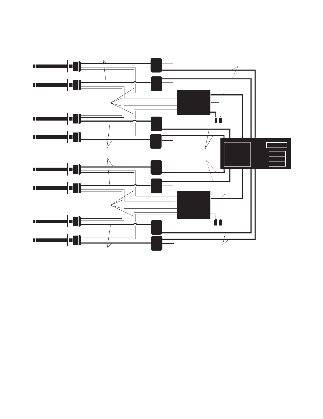
Section 2, Installation. Figure 1-4 is a block
diagram illustrating six World Class 3000
Probes applied to the Control Room Electronics. Figure 1-5 shows the same information but for an eight probe configuration.
After selecting the probe mounting location,
provision should be made for a platform
where the probe can be easily serviced. The
heater power supply can be located up to
150 feet (46 m) cabling distance from the
probe, and up to 1200 feet (366 m) cabling
distance from the control room electronics.
A source of instrument air is required at the
probe for reference gas use. Since the
probe is equipped with an in-place calibration feature, provision should be made for
connecting test gas tanks to the oxygen
analyzer when the probe is to be calibrated.
If test gas bottles will be hooked up permanently, a check valve must be installed next
to the calibration fittings on the probe junction box. This is to prevent breathing of calibration gas line and subsequent flue gas
condensation and corrosion. The check
valve is in addition to the stop valve in the
test gas kit or the solenoid valve in the multiprobe test gas sequencer units.
An optional Z-purge arrangement is available for applications where hazardous area
classification may be required. (See Application Data Bulletin AD 106-300B.)
1-4 Description Rosemount Analytical Inc. A Division of Emerson Process Management

World Class 3000
1
Instruction Manual
IB-106-300NC Rev. 4.4
February 1998
CALIBRATION
INSTRUMENT
AIR SUPPLY
(REF. GAS)
GAS
PRESSURE
REGULATOR
FLOWMETER
CONTROL ROOM
ELECTRONICS
GASES
STACK
STANDARD
DUCT
OXYGEN
ANALYZER
(PROBE)
HEATER POWER SUPPLY
MULTIPROBE
TEST GAS
SEQUENCER
ADAPTER
PLATE
LINE
VOLTAGE
1
2
AS
AS
.AIR
ST
IN
TEST G
TEST G
GASES
STACK
ADAPTER
PLATE
CALIBRATION
GAS
SUPPLY
REFERENCE AIR
OPTIONS
DUCT
OXYGEN
ANALYZER
(PROBE)
HEATER
POWER
SUPPLY
LINE
VOLTAGE
CONTROL ROOM
ELECTRONICS
19270002
Figure 1-2. Typical System Installation
Rosemount Analytical Inc. A Division of Emerson Process Management Description 1-5

Instruction Manual
IB-106-300 NC Rev. 4.4
February 1998
World Class 3000
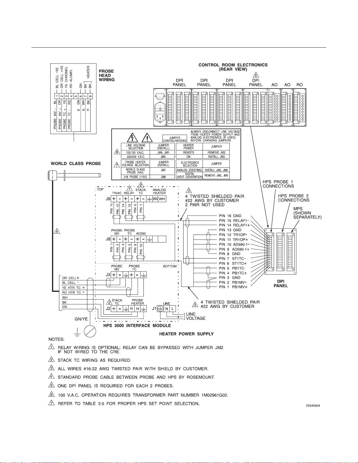
Figure 1-3. Typical System Wiring (Sheet 1 of 3)
1-6 Description Rosemount Analytical Inc. A Division of Emerson Process Management

World Class 3000
1
REMOTE MOMENTARY
CALIBRATION START
SWITCH BY CUSTOMER
PROBE 2
PROBE 1
PIN 16 CALINT2
PIN 15 CALINT2+
PIN 14 CALINT1
PIN 13 CALINT1+
PIN 12 CALRET2
PIN 11 NOGAS2
PIN 10 GND
PIN 9 LOGAS2
PIN 8 HIGAS2
PIN 7 INCAL2
PIN 6 CALRET1
PIN 5 NOGAS1
PIN 4 GND
PIN 3 LOGAS1
PIN 2 HIGAS1
PIN 1 INCAL1
Instruction Manual
IB-106-300NC Rev. 4.4
February 1998
-
-
DETAIL B
TO DPI FOR
PIN 1
PROBES 3 AND 4
PIN 7
IF REQUIRED
PIN 3
PIN 6
PIN 5
PIN 1
PIN 2
PIN 7
8 CONDUCTOR
SHIELDED CABLE
#16 AWG BY CUSTOMER
PIN 1
PIN 7
DUPLICATE CONNECTIONS
NOT REQUIRED
PROBE 1 PROBE 2 PROBE 3 PROBE 4
LINE OUT LINE IN
L
IN CAL
HI GAS
N
CAL RET
NO GAS
LOW GAS
IN CAL
HI GAS
CAL RET
NO GAS
LOW GAS
IN CAL
HI GAS
CAL RET
NO GAS
LOW GAS
HI GAS
J10
NC C NO NC C NO NC C NO NC C NO
J13 J14 J15 J16 J17 J18
J11
PROBE 1
MULTIPROBE GAS SEQUENCER (OPTIONAL) MPS 3000 TYPICAL CONFIGURATION
PROBE 2 PROBE 3 PROBE 4
REFER TO MPS MODEL NUMBER FOR SPECIFIC CONFIGURATION
IN CAL
CAL RET
NO GAS
LOW GAS
L
N
J12
L
E
N
LINE
VOLTAGE
CRE AND MPS CONNECTIONS
Figure 1-3. Typical System Wiring (Sheet 2 of 3)
Rosemount Analytical Inc. A Division of Emerson Process Management Description 1-7

Instruction Manual
IB-106-300 NC Rev. 4.4
February 1998
World Class 3000
Figure 1-3. Typical System Wiring (Sheet 3 of 3)
1-8 Description Rosemount Analytical Inc. A Division of Emerson Process Management

World Class 3000
1
7 Conductor Cable
(150 Feet Max)
World Class 3000
Probe
HPS
3000
HPS
3000
Line Voltage
Line Voltage
Instruction Manual
IB-106-300NC Rev. 4.4
February 1998
4 Twisted Pair Plus 2 Twisted Pair
for Options (1200 Feet Max)
8 Conductor Wire
(1000 Feet Max)
World Class 3000
Probe
2 Pneumatic Lines
by Customer
(300 Feet Max)
7 Conductor Cable
(150 Feet Max)
7 Conductor Cable
(150 Feet Max)
2 Pneumatic Lines
by Customer
(300 Feet Max)
7 Conductor Cable
(150 Feet Max)
Test Gas
Sequencer
MPS 3000
Modular Design
HPS
3000
4 Twisted Pair Plus 2 Twisted Pair
4 Twisted Pair Plus 2 Twisted Pair
HPS
3000
HPS
3000
HPS
3000
Up to 4 Probes
Line Voltage
for Options (1200 Feet Max)
for Options (1200 Feet Max)
Line Voltage
Line Voltage
Test Gas
Sequencer
MPS 3000
Modular Design
Up to 4 Probes
Line Voltage
4 Twisted Pair Plus 2 Twisted Pair
for Options (1200 Feet Max)
Line Voltage
Test Gas
by Customer
8 Conductor Wire
(1000 Feet Max)
Line Voltage
Test Gas
by Customer
Line Voltage
CRE 3000
Control Room
Electronics
Line Voltage
100 to 120 Volt
220 to 240 Volt
19270004
Figure 1-4. Control Room Electronics with 6 World Class 3000 Probes
Rosemount Analytical Inc. A Division of Emerson Process Management Description 1-9
Instruction Manual
IB-106-300 NC Rev. 4.4
February 1998
World Class 3000
Probe
7 Conductor Cable
(150 Feet Max)
HPS
3000
HPS
3000
Line Voltage
Line Voltage
World Class 3000
4 Twisted Pair Plus 2 Twisted Pair
for Options (1200 Feet Max)
8 Conductor Wire
(1000 Feet Max)
World Class 3000
Probe
2 Pneumatic Lines
by Customer
(300 Feet Max)
7 Conductor Cable
(150 Feet Max)
2 Pneumatic Lines
by Customer
(300 Feet Max)
7 Conductor Cable
(150 Feet Max)
Test Gas
Sequencer
MPS 3000
Modular Design
HPS
3000
HPS
3000
4 Twisted Pair Plus 2 Twisted Pair
HPS
3000
HPS
3000
HPS
3000
HPS
3000
Up to 4 Probes
Line Voltage
Line Voltage
for Options (1200 Feet Max)
Line Voltage
Line Voltage
Test Gas
Sequencer
MPS 3000
Modular Design
Up to 4 Probes
Line Voltage
Line Voltage
Line Voltage
Test Gas
by Customer
8 Conductor Wire
(1000 Feet Max)
Line Voltage
Test Gas
by Customer
4 Twisted Pair Plus 2 Twisted Pair
for Options (1200 Feet Max)
Line Voltage
CRE 3000
Control Room
Electronics
Line Voltage
100 to 120 Volt
220 to 240 Volt
19270005
Figure 1-5. Control Room Electronics with 8 World Class 3000 Probes
1-10 Description Rosemount Analytical Inc. A Division of Emerson Process Management
World Class 3000
2
Instruction Manual
IB-106-300NC Rev. 4.4
February 1998
SECTION 2
INSTALLATION
2-1 OXYGEN ANALYZER (PROBE)
INSTALLATION
Before starting to install this equipment, read the "Safety instructions for
the wiring and installation of this apparatus" at the front of this Instruction
Bulletin. Failure to follow the safety
instructions could result in serious
injury or death.
Install all protective equipment covers
and safety ground leads after installation. Failure to install covers and
ground leads could result in serious
injury or death.
a. Selecting Location.
1. The location of the probe in the stack
or flue is most important for maximum
accuracy in the oxygen analyzing process. The probe must be positioned, so
that the gas it measures is representative of the process. Best results are
normally obtained if the probe is positioned near the center of the duct (40
to 60% insertion). A point too near the
edge or wall of the duct may not provide a representative sample because
of the possibility of gas stratification. In
addition, the sensing point should be
selected, so that the process gas temperature falls within a range of 50° to
1300°F (10° to 704°C). Figure 2-1 provides mechanical installation
references.
2. Check the flue or stack for holes and
air leakage. The presence of this condition will substantially affect the accuracy of the oxygen reading. Therefore,
either make necessary repairs or install
the probe upstream of any leakage.
3. Ensure that the area is clear of obstructions, internal and external, that
will interfere with installation. Allow
adequate clearance for removal of
probe (Figure 2-1).
4. If the probe is to be mounted outside
and subject to rain and snow conditions, make sure the back of the probe
(outside of the duct) is insulated to prevent the formation of flue gas condensate in the calibration gas lines.
Do not allow the temperature of the
probe junction box to exceed 300°F
(149°C) or damage to the unit may result. If the probe junction box temperature exceeds 300°F (149°C), the
user must fabricate a heat shield or
provide adequate cooling air to the
probe junction box.
b. Mechanical Installation.
1. Ensure that all components are available for installation of the probe. Ensure that the system cable is the
required length. If applicable, check the
optional ceramic diffusor to ensure that
it is not damaged.
2. The probe may be installed intact as it
is received. It is recommended that you
disassemble the adapter plate for each
installation.
NOTE
An abrasive shield is recommended
for high velocity particulate in the flue
stream (such as those in pulverized
coal kilns and recovery boilers). Vertical and horizontal brace clamps are
provided for 9 ft and 12 ft (2.75 m and
3.66 m) probes to provide mechanical
support of the probe. Refer to Figure
2-1, sheet 5.
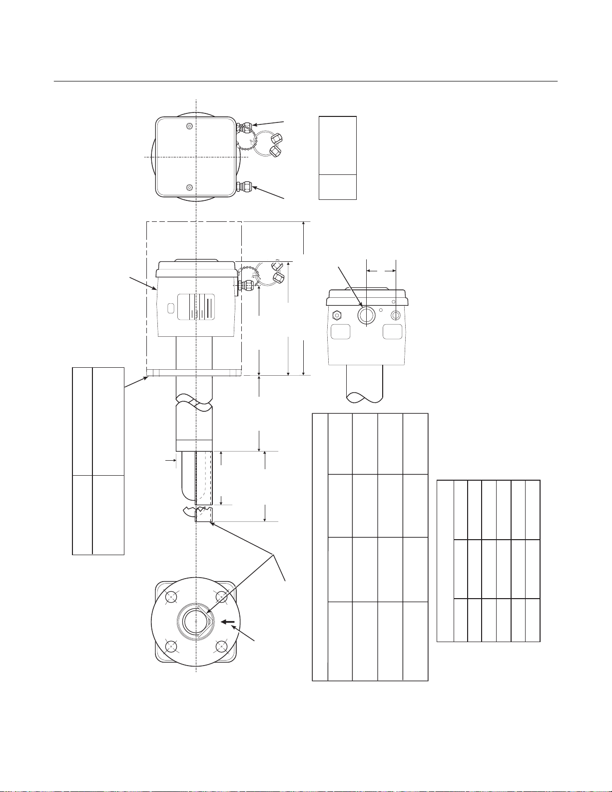
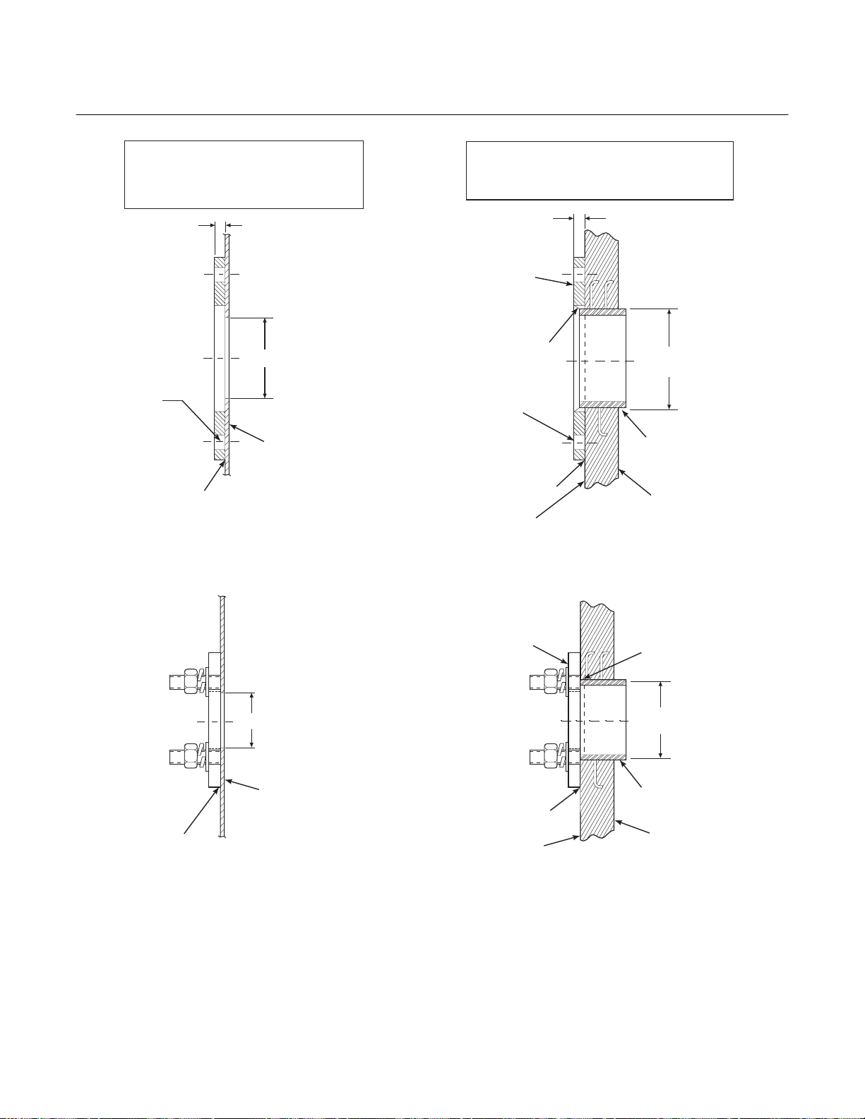
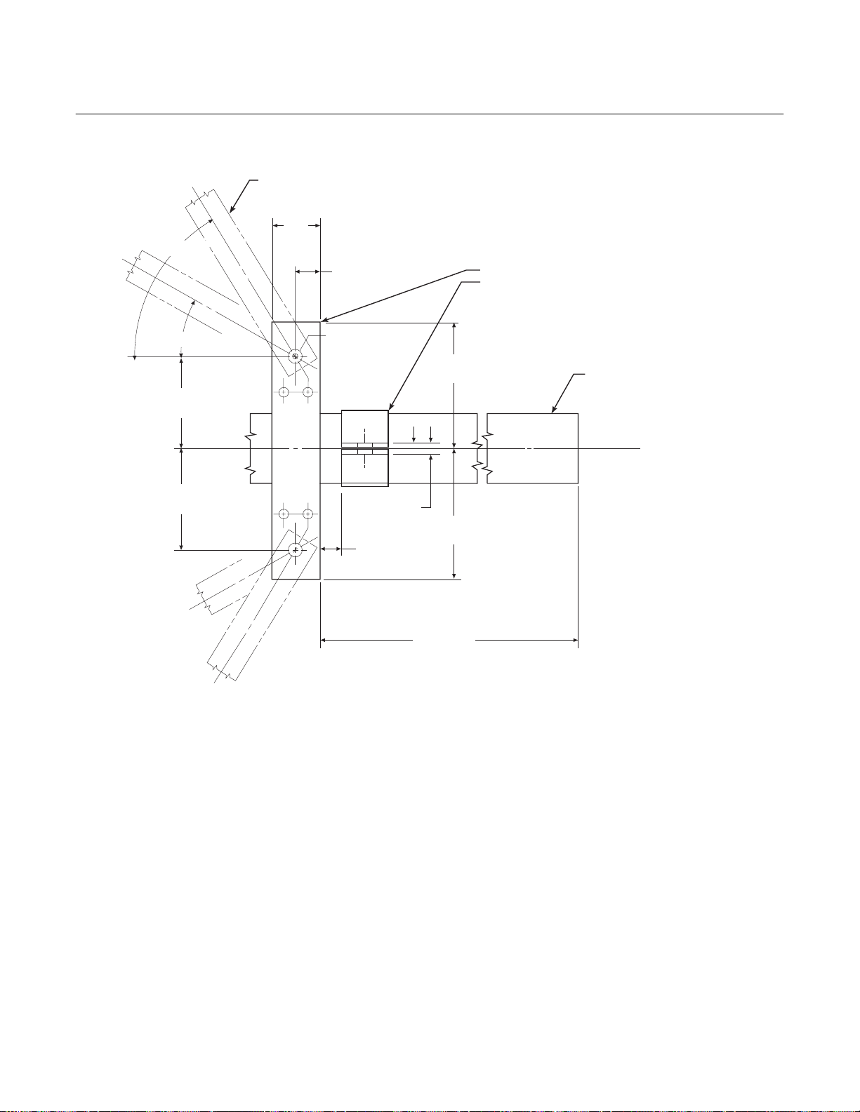
3. Weld or bolt adapter plate (Figure 2-1)
onto the duct.
Rosemount Analytical Inc. A Division of Emerson Process Management Installation 2-1
Instruction Manual
IB-106-300 NC Rev. 4.4
February 1998
World Class 3000
FURNISHED IN - XIT
4512C34
ADAPTER & ACCESSORY
TO AMBIENT
INSULATE IF EXPOSED
WEATHER CONDITIONS
4512C35
4512C36
2.27 (58)
DIA MAX
ROSEMOUNT
5.85 (148.6)
DIM "A"
WITH STANDARD
REF GAS
CAL GAS
7.58 (192)
SNUBBER
DIFFUSER
ELEC
DIM "B" REMOVAL ENVELOPE
1/4 IN. TUBE
6 MM TUBE
6 MM TUBE
ANSI
DIN
JIS
1/2"
CONN
CONDUIT
GAS
CAL
JIS
4512C18H01
6.10
(155)
1.88 (48)
0.59
GAS
REF
(15)
AT THE BOTTOM
BOTTOM VIEW
INSTALL WITH CONNECTIONS
5.12
(130)
THESE FLAT FACED FLANGES ARE MANUFACTURED
TO ANSI, DIN, AND JIS BOLT PATTERNS AND ARE NOT
DIMENSIONS ARE IN INCHES WITH MILLIMETERS IN
PARENTHESES.
PRESSURE RATED.
2.
NOTES: 1.
24610001
3.80 (96.5)
DIFFUSER
FOR PROBE
WITH CERAMIC
4.90 (124.5)
ADD TO DIM "A" FOR
ARRESTOR
DIFFUSER AND FLAME
PROBE WITH CERAMIC
DIN
7.28
4512C19H01
ANSI
6.00
4512C17H01
(185)
(153)
0.71
0.75
(18)
(20)
5.71
(145)
4.75
(121)
DIM "B"
DIM "A"
27.3 (694)
16 (406)
45.3 (1151)
34 (864)
81.3 (2065)
117.3 (2980)
70 (1778)
106 (2692)
153.3 (3894)
142 (3607)
3535B18H02
3635B48H01
ANSI
JIS
0.062 THK GASKET
ADD TO DIM "A"
3535B45H01
DIN
TABLE I MOUNTING FLANGE
3FT
6FT
9FT
12 FT
PROCESS FLOW MUST
BE IN THIS DIRECTION
WITH RESPECT TO
DEFLECTOR 3534848G01
FLANGE
DIA.
HOLE
DIA.
(4) HOLES
EQ SP ON BC
TABLE II INSTALLATION/REMOVAL
18 IN.
PROBE
Figure 2-1. Probe Installation (Sheet 1 of 5)
2-2 Installation Rosemount Analytical Inc. A Division of Emerson Process Management

World Class 3000
2
7.50
7.48
BOLT
CIRCLE
0.75
(8) HOLES
DIAMETER
FLANGE
9.00 (153)
DIAMETER
TABLE IV. FLANGE SIZE
*
ANSI
7.48
0.75
0.945
9.25 (235)
9.25 (235)
*
*
JIS
DIN
5.7
(145)
14.5
(369)
DIM "D" REMOVAL ENVELOPE
PRESSURE RATED.
FLATFACED. THESE FLANGES ARE NOT
DIN, AND JIS BOLTPATTERNS AND ARE
FLANGES ARE MANUFACTURED TO ANSI,
*
7.00
(178)
SEE TABLE IV
FOR FLANGE
SIZES
Instruction Manual
IB-106-300NC Rev. 4.4
February 1998
21190008
REF AND
CAL GAS
CONNECTOR
ELECTRICAL
CONNECTOR
CAL GAS LINES
CHECK VALVE FOR
INSULATE IF
CONDITIONS
EXPOSED TO
AMBIENT WEATHER
31.1
(790)
DIM "E"
45.3
(1151)
DIM "D"
27
(686)
DIM "C"
NOMINAL MEASUREMENTS
TABLE III. REMOVAL/ INSTALLATION
3 FT
67.1
81.3
63
6 FT
(1704)
(2065)
(1600)
103.1
139.1
(2619)
(3533)
117.3
153.3
(3894)
(2980)
(P/N 3535B58G04 - JIS)
99
9 FT
(2515)
135
(3429)
12 FT
DIM "C"
0.06 THK GASKET FURNISHED
DIM "E" (WITH FLAME ARRESTOR)
(P/N 3535B58G06 - DIN)
(P/N 3535B58G02 - ANSI)
IN HARDWARE PACKAGE
Figure 2-1. Probe Installation (Sheet 2 of 5)
3.6
NOMINAL
(P/N 4843B38G02)
SNUBBER DIFFUSION/
DUST SEAL ASSEMBLY
DIMENSIONS ARE IN INCHES WITH
MILLIMETERS IN PARENTHESES.
NOTE:
Rosemount Analytical Inc. A Division of Emerson Process Management Installation 2-3

Instruction Manual
IB-106-300 NC Rev. 4.4
February 1998
World Class 3000
JIS
(P/N 3535B58G04)
DIN
(P/N 3535B58G06)
ANSI
(P/N 3535B58G02)
IN.
TABLE VI. ADAPTOR PLATE DIMENSIONS FOR ABRASIVE SHIELD
(mm)
DIMENSIONS
JIS
(P/N 4512C35G01)
9.25
9.25
9.00
"A"
6.50
(235)
(235)
(229)
(165)
4.92
(125)
(M-20 x 2.5)
3.94
(100)
(M-16 x 2)
4.75
(121)
0.625-11
"C"
"B"
DIA
THREAD
(130)
5.118
(M-12 x 1.75)
7.894
7.48
7.50
"D"
(200)
(190)
(191)
DIA
NOTE: PART NUMBERS FOR ADAPTOR PLATES INCLUDE
ATTACHING HARDWARE.
o
22.5
OUTSIDE WALL SURFACE.
CROSSHATCHED AREA IN 4
CORNERS MAY BE USED TO
FIELD BOLTING OF PLATE TO
PROVIDE ADDITIONAL HOLES FOR
AND 12 FT ABRASIVE SHIELD
ADAPTOR PLATE FOR 3, 6, 9,
INSTALLATIONS. SEE SHEET 2.
8 THREADED HOLES
EQUALLY SPACED ON
D DIA B.C.
A
ABRASIVE SHIELD
FLANGE O.D.
C
A
B
4 STUDS,
LOCKWASHERS AND
NUTS EQUALLY
SPACED ON
DIN
ANSI
TABLE V. ADAPTOR PLATE DIMENSIONS FOR PROBE
IN.
DIMENSIONS
7.5
(191)
(M-16 x 2)
(P/N 4512C36G01)
6.00
(153)
0.625-11
(P/N 4512C34G01)
"B"
"A"
(mm)
THREAD
(145)
5.708
4.75
(121)
"C"
DIA
A
o
45
A
C
ATTACHING HARDWARE.
2.500 DIA
NOTE: PART NUMBERS FOR ADAPTOR PLATES INCLUDE
C DIA B.C.
B
ORLD CLASS 3000
ADAPTOR PLATE FOR
STD W
PROBE INSTALLATION.
SEE SHEET 1.
Figure 2-1. Probe Installation (Sheet 3 of 5)
2-4 Installation Rosemount Analytical Inc. A Division of Emerson Process Management
World Class 3000
2
Instruction Manual
IB-106-300NC Rev. 4.4
February 1998
INSTALLATION FOR METAL
WALL STACK OR DUCT
CONSTRUCTION
MTG HOLES
SHOWN ROTATED
o
45 OUT OF
TRUE POSITION
WELD OR BOLT ADAPTOR
PLATE TO METAL WALL
OF STACK OR DUCT.
JOINT MUST BE AIR TIGHT.
0.50 [13]
3.75 [95]
MIN DIA HOLE
IN WALL
STACK OR DUCT
METAL WALL
INSTALLATION FOR MASONRY
WALL STACK CONSTRUCTION
0.50 [13]
BOLT ADAPTOR
PLATE TO OUTSIDE
WALL SURFACE
FIELD WELD
PIPE TO
ADAPTOR PLATE
MTG HOLES
SHOWN ROTATED
o
45 OUT OF
TRUE POSITION
JOINT MUST
BE AIRTIGHT
OUTSIDE WALL
SURFACE
NOTE: ALL MASONRY STACK WORK AND JOINTS EXCEPT
ADAPTOR PLATE NOT FURNISHED BY ROSEMOUNT.
4.50 [114]
O.D. REF
PIPE 4.00 SCHED 40
PIPE SLEEVE (NOT
BY ROSEMOUNT)
LENGTH BY CUSTOMER
MASONRY
STACK WALL
WELD OR BOLT ADAPTOR
PLATE TO METAL WALL
OF STACK OR DUCT.
JOINT MUST BE AIR TIGHT.
2.50 [63.5]
MIN DIA HOLE
IN WALL
STACK OR DUCT
METAL WALL
Figure 2-1. Probe Installation (Sheet 4 of 5)
BOLT ADAPTOR
PLATE TO OUTSIDE
WALL SURFACE
JOINT MUST
BE AIRTIGHT
OUTSIDE WALL
SURFACE
NOTE: DIMENSIONS IN INCHES WITH
MILLIMETERS IN PARENTHESES.
FIELD WELD
PIPE TO
ADAPTOR PLATE
3.50 [89]
O.D. REF
PIPE 3.00 SCHED 40
PIPE SLEEVE (NOT
BY ROSEMOUNT)
LENGTH BY CUSTOMER
MASONRY
STACK WALL
624038
Rosemount Analytical Inc. A Division of Emerson Process Management Installation 2-5
Instruction Manual
IB-106-300 NC Rev. 4.4
February 1998
World Class 3000
60oMAX.
o
30
MIN.
4.12
(105)
4.12
(105)
BRACE BARS
(NOT BY ROSEMOUNT)
2.00
(51)
1.00
(25)
2 HOLES - 0.625
(16) DIA. FOR
0.50 (12) DIA.
BOLT
1.00
(25) MAX.
0.375
(10)
NOTE: DIMENSIONS IN INCHES WITH
MILLIMETERS IN PARETHESES.
VERTICAL BRACE CLAMP ASSY.
HORIZONTAL BRACE CLAMP ASSY.
(BOTH BRACE CLAMP ASSEMBLIES ARE THE SAME.
INSTALLATION AND LOCATION OF CLAMP ASSEMBLIES
AND BRACE BARS TO BE DONE IN FIELD.)
5.62
(143)
5.62
(143)
ABRASIVE SHIELD
BY ROSEMOUNT
}
36.00 (914)
NOTE: BRACING IS FOR VERTICAL AND HORIZONTAL PROBE INSTALLATION.
EXTERNAL BRACING REQUIRED FOR 9 FT AND 12 FT
(2.75 M AND 3.66 M) PROBES AS SHOWN ABOVE.
Figure 2-1. Probe Installation (Sheet 5 of 5)
2-6 Installation Rosemount Analytical Inc. A Division of Emerson Process Management

World Class 3000
2
Instruction Manual
IB-106-300NC Rev. 4.4
February 1998
APEX
FILTER
4. If using the optional ceramic diffusor
5. In horizontal installations, the probe
6. If the system has an abrasive shield,
GAS FLOW
DIRECTION
VEE
DEFLECTOR
element, the vee deflector must be correctly oriented. Before inserting the
probe, check the direction of flow of the
gas in the duct. Orient the vee deflector
on the probe, so that the apex points
upstream toward the flow (Figure 2-2).
This may be done by loosening the
setscrews, and rotating the vee deflector to the desired position.
Retighten the setscrews.
junction box should be oriented, so that
the system cable drops vertically from
the probe junction box. In a vertical installation, the system cable can be oriented in any direction.
check the diffusion element dust seal
packings. The joints in the two packings must be staggered 180°. Also,
DIFFUSION
ELEMENT
SETSCREW
make sure that the packings are in the
hub grooves as the probe slides into
the 15° forcing cone in the abrasive
shield.
7. Insert the probe through the opening in
the mounting flange and bolt the unit to
the flange. When probe lengths selected are 9 or 12 feet (2.74 or 3.66 m),
special brackets are supplied to provide additional support for the probe
inside the flue or stack. See Figure 2-1,
sheet 5.
c. Reference Air Package
After the oxygen analyzing (probe) unit is
installed, connect the reference gas air set
to the probe junction box. The reference gas
air set should be installed in accordance
with Figure 2-3.
d. Service Required
1. Power input: 100, 115 or 220 Vac
single phase, 50 to 60 Hz, 6 amp
minimum. (See label.)
2. Compressed air: 10 psig (68.95
kPag) minimum, 225 psig (1551.38
kPag) maximum at 2 scfh (56.6 L/hr)
maximum; supplied by one of the following (less than 40 parts-per-million
total hydrocarbons). Regulator outlet
pressure should be set at 5 psi (35
kPa).
VEE
DEFLECTOR
(a) Instrument air - clean, dry.
(b) Bottled standard air with step-down
regulator.
(c) Bottled compressed gas mixture
(20.95% oxygen in nitrogen).
Figure 2-2. Orienting the Optional Vee Deflector
(d) Other equivalent clean, dry, oil-free
air supply.
Rosemount Analytical Inc. A Division of Emerson Process Management Installation 2-7

Instruction Manual
IB-106-300 NC Rev. 4.4
February 1998
World Class 3000
0.125-27 NPT FEMALE
OUTLET CONNECTION
1
4.81 (122.17)
FLOW SET
POINT KNOB
0.250 OR 6 MM OD
TUBE COMPRESSION
FITTING (SUPPLIED BY WECO)
0.250 OR 6 MM OD TUBING
(SUPPLIED BY CUSTOMER)
SCHEMATIC HOOKUP FOR REFERENCE AIR SUPPLY ON OXYGEN ANALYZER PROBE HEAD.
2
OUTLET
1.19
(30.22)
DRAIN VALVE
10.0 REF
(254)
TO PROBE
JUNCTION BOX
3
REF GAS SET
263C152G01
3.12 (79.25) MAX
2.250 (57.15)
0.25-18 NPT FEMALE
INLET CONNECTION
2.0
(50.80)
1.50
(38.10)
1 FLOWMETER 0.2-2.0 SCFH 771B635H02
2 2" PRESSURE GAGE 0-15 PSIG 275431-006
3 COMBINATION FILTER-REG. 0-30 PSIG 4505C21G01
NOTE: DIMENSIONS ARE IN INCHES WITH
2 MOUNTING HOLES
3.19 (81.03) LG
THROUGH BODY FOR
0.312 (7.92) DIA BOLTS
COMPRESSED AIR SUPPLY
10-225 PSIG MAX PRESSURE
MILLIMETERS IN PARENTHESES.
8.50 MAX
(215.90)
703020
Figure 2-3. Air Set, Plant Air Connection
2-2 CONTROL ROOM ELECTRONICS MODULE
INSTALLATION
a. Mechanical Installation
Install CRE in 19 inch (483 mm) rack using
rack mount brackets. Refer to Figure 2-4
for CRE dimensions. If installing CRE in a
panel, see Figure 2-5 for panel cutout dimensions. If installing CRE in a wall with the
optional trim frame, refer to paragraph 2-2g,
Optional Trim Frame and Rear Cover, and
Figure 2-11.
b. Electrical Connections
1. The power cable used should comply
with safety regulations in the user's
country.
2-8 Installation Rosemount Analytical Inc. A Division of Emerson Process Management

World Class 3000
2
TOP VIEW
17.62
(447,55)
19.00
(482,60)
13.25
(336,55)
16.25
(412,75)
WITH CABLE
CLEARANCE
DIMENSIONS IN INCHES WITH
NOTE:
MILLIMETERS IN PARENTHESES.
Instruction Manual
IB-106-300NC Rev. 4.4
February 1998
FRONT VIEW
0.30 DIA (4 PLS)
2.25
(57,15)
Figure 2-5. Panel Cutout for Control Room Electronic Module
5.22
(132,59)
SIDE VIEW
Figure 2-4. Control Room Electronic Dimensions
CUTOUT
17.75
(450,85)
18.31
(465,07)
5.36
(136,14)
5.22
(132,59)
Rosemount Analytical Inc. A Division of Emerson Process Management Installation 2-9

Instruction Manual
IB-106-300 NC Rev. 4.4
February 1998
World Class 3000
2. Plug the female end of the power cable
into the AC IN plug on the back of the
CRE, Figure 2-6.
3. Plug the male end of the power cable
into any acceptable power outlet for
the voltage configured.
NOTE
Refer to Figure 2-6 for CRE unit fuse
locations and specifications.
c. Analog Output and Relay Output
Connections
1. The analog outputs and relay outputs
are programmed by the user as
needed. Analog outputs are typically
sent to recording equipment such as
chart recorders. Relay outputs are typically sent to annunciators.
2. All wiring must conform to local and
national codes.
3. Connect the analog outputs and relay
outputs as shown in Figure 2-6.
Figure 2-6. CRE Power, Analog Output, and Relay Output Connections
2-10 Installation Rosemount Analytical Inc. A Division of Emerson Process Management

World Class 3000
2
Instruction Manual
IB-106-300NC Rev. 4.4
February 1998
Table 2-1. Analog Output Card Jumper
Configuration
OUTPUT
NUMBER JM1 JM2
1-4
5-8
9-12
IN
OUT
IN
IN
IN
OUT
d. Analog Output Card Jumper
Configuration
The CRE can have up to three analog output circuit boards. The jumpers on these
boards are set at the factory. Should a system ever be expanded, or in the event of
board replacement, the jumper configurations for each card are given in Table 2-1.
Refer to Figure 2-7 for the location of the
jumpers on the analog output card.
e. Relay Output Panel Jumper
Configuration
The relay output contacts can be configured
to be normally open or normally closed. This
is done by moving jumpers on the relay output card.
ANALOG OUTPUT CARD
JM1 JM2
Refer to moving jumpers on the relay output
card. Refer to Figure 2-8. The jumpers are
placed on the first two pins for normally
closed contacts and on the last two pins for
normally open contacts. Jumpers JM1 and
JM2 on the relay output card, Figure 2-9,
are installed at the factory.
f. Dual Probe Interface (DPI) Card
Configuration
A CRE may be configured with up to four
DPI cards. Refer to Table 2-2 and Figure
2-10 for DPI card jumper configurations.
Table 2-2. DPI Card Jumper Configuration
CARD
JM1 JM2
NUMBER
1
2
3
4
FOR NORMALLY
CLOSED CONTACTS
PLACE THE
JUMPER ON THE
FIRST TWO PINS.
FOR NORMALLY
OPEN CONTACTS
PLACE THE
JUMPER ON THE
LAST TWO PINS.
IN
OUT
IN
OUT
NO NC
16
15
14
13
NO NC
12
11
10
9
NO NC
8
7
6
5
NO NC
4
3
2
1
OUT
OUT
JM
18
JM
17
JM
16
JM
15
JM
14
JM
13
JM
12
JM
1
1
JM
10
JM
9
JM
8
JM
7
JM
6
JM
5
JM
4
JM
3
IN
IN
21200001
Figure 2-7. Analog Output Card Jumpers
Figure 2-8. Relay Output Panel Jumper
Configuration
Rosemount Analytical Inc. A Division of Emerson Process Management Installation 2-11

Instruction Manual
IB-106-300 NC Rev. 4.4
February 1998
JM1
JM1 JM2
JM2
Figure 2-9. Relay Output Card Jumper
Configuration
g. Optional Trim Frame and Rear Cover
The trim frame slides over the unit as shown
in Figure 2-11. The trim frame covers wall
World Class 3000
Figure 2-10. DPI Card Jumpers
cuts. The rear cover mounts to the back of
the unit with the same screws holding the
trim strips, Figure 2-11. The rear cover protects wires and terminals. The panel
mounting kit contains a trim frame and back
cover. The part number for the panel
mounting kit is 1L03636G01.
Figure 2-11. Optional Trim Frame and Rear Cover
2-12 Installation Rosemount Analytical Inc. A Division of Emerson Process Management

World Class 3000
2
Instruction Manual
IB-106-300NC Rev. 4.4
February 1998
2-3 HEATER POWER SUPPLY INSTALLATION
a. Mechanical Installation
The outline drawing of the heater power
supply enclosure in Figure 2-12, shows
mounting centers and clearances. The
NEMA 4X enclosure is designed to be
mounted on a wall or bulkhead. The heater
power supply should be installed no further than 150 feet (45 m) from the probe.
The heater power supply must be located in
a location free from significant ambient temperature changes and electrical noise. Ambient temperature must be between -20° to
140°F (-30° to 60°C).
b. Electrical Connections
1. Electrical connections should be made
as described in the electrical installation diagram, Figure 2-13. The wiring
terminals are divided into two layers:
the bottom (FROM PROBE) terminals
3.25
(82.6)
NOTE: DIMENSIONS IN INCHES
7.00
(177.8)
WITH MILLIMETERS IN PARENTHESES.
3.63
(92.2)
NEMA 4X
(NON-HAZARDOUS)
should be connected first, the top
(FROM ELECTRONICS) terminals
should be connected last (Figure 2-14).
Each terminal strip has a protective
cover which must be removed when
making connections. To remove the
terminal covers, remove two slotted
screws holding cover in place. Always
reinstall terminal covers after making
connections. All wiring must conform to
local and national codes.
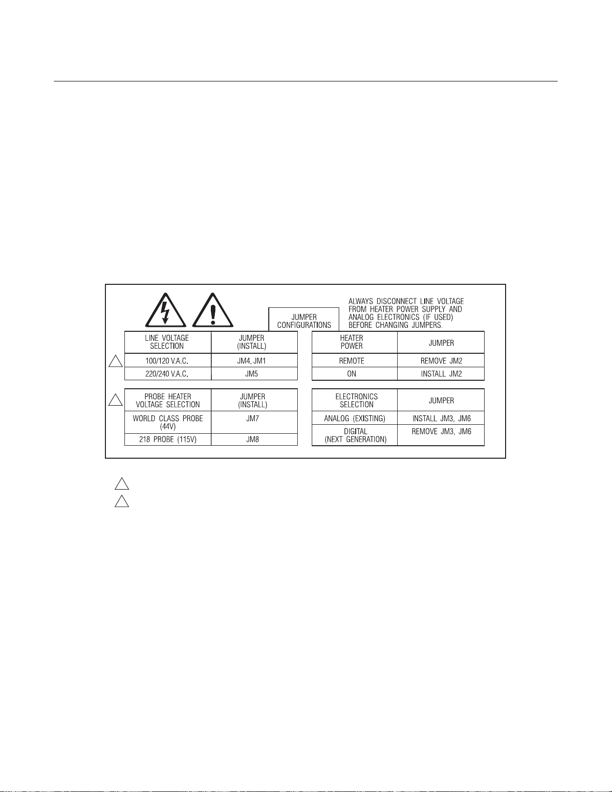
NOTE
Before supplying power to the heater
power supply, verify that jumpers JM3
and JM6 are removed, and JM7 is installed. JM2 is installed, if relay is not
wired.
NOTE
Refer to Figure 2-16 for HPS unit fuse
locations and specifications.
10.39
(264)
8.50
(215.9)
6.18
(156.9)
0.56 (14)
DIA (2)
MOUNTING
HOLES
686029
4.00
(101.6)
(215.9)
8.50
0.31
(7.9)
#0.31
6.00
(152.4)
(124)
6.75
(171.5)
0.13" (3.3) THK U. L. APPROVED
GASKET
1.81
(46)
4.88
(203.2)
#10-32 UNF 2A
THREADED INSERT
(0.31 x 0.31 FROM CORNER OF PLATE)
8.00
11.00
(279.4)
4.38
(111.3)
9.96
(253)
0.38
(9.7)
1.00 (25.4) MINIMUM CLEARANCE
4.72
(120)
CLASS 1, DIVISION 1, GROUP B ENCLOSURE
FOR REMOVING COVER
9.17
(233)
Figure 2-12. Outline of Heater Power Supply
Rosemount Analytical Inc. A Division of Emerson Process Management Installation 2-13
Instruction Manual
IB-106-300 NC Rev. 4.4
February 1998
World Class 3000
Figure 2-13. Electrical Installation of Heater Power Supply
2-14 Installation Rosemount Analytical Inc. A Division of Emerson Process Management

World Class 3000
2
TRANSFORMER
Instruction Manual
IB-106-300NC Rev. 4.4
February 1998
TERMINAL
COVERS
FRONT
TERMINAL STRIP
(FROM ELECTRONICS)
TRANSFORMER
TERMINAL STRIP
(FROM PROBE)
SIDE
Figure 2-14. Heater Power Supply Wiring Connections
29850005
Rosemount Analytical Inc. A Division of Emerson Process Management Installation 2-15
Instruction Manual
IB-106-300 NC Rev. 4.4
February 1998
World Class 3000
2. Power Input: 120, 220 or 240 Vac. For
120 Vac usage, install jumpers JM4
and JM1. For 220 or 240 Vac usage,
install jumper JM5 (see label, Figure 2-
15).
NOTE
For 100 Vac usage, the heater power
supply is factory-supplied with a different transformer. When using the
HPS with 100 Vac transformer, install
jumpers JM1 and JM4.
1
3. The power cable should comply with
safety regulations in the user's country
and should not be smaller than 16
gauge, 3 amp.
4. Before supplying power to the heater
power supply, verify that the jumpers
on the mother board, Figure 2-16, are
properly configured. Jumpers JM3 and
JM6 should be removed, and JM7
should be installed. Additionally, make
sure that the proper jumper for your
line voltage is installed, Figure 2-15.
JM2 is installed if relay is not wired.
2
NOTES:
100 V.A.C. OPERATION REQUIRES TRANSFORMER PART NUMBER 1M02961G02.
1
REFER TO TABLE 3-6 FOR PROPER SET POINT SELECTION.
2
Figure 2-15. Jumper Selection Label
2-16 Installation Rosemount Analytical Inc. A Division of Emerson Process Management

World Class 3000
2
JM1
Instruction Manual
IB-106-300NC Rev. 4.4
February 1998
JM2
JM4
JM7
Figure 2-16. Jumpers on HPS Mother Board
2-4 MULTIPROBE TEST GAS SEQUENCER
INSTALLATION
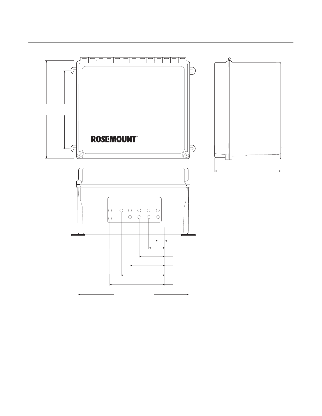
a. Mechanical Installation
The outline drawing of the MPS module in
Figure 2-17 shows mounting centers and
clearances. The box is designed to be
mounted on a wall or bulkhead. The MPS
module should be installed no further than
300 feet (91 m) piping distance from the
probe, and no more than 1000 feet (303 m)
cabling distance from the CRE. Install the
MPS module in a location where the ambient temperature is between -20° to 160°F
(-30° to 71°C).
b. Gas Connections
3D3 080G REV
JM5
JM8
JM3
JM6
2. Connect the high O
test gas to HIGH
2
GAS. The test gas pressure should be
set at 20 psi (138 kPa).
3. Connect the low O
test gas to LOW
2
GAS. The test gas pressure should be
set at 20 psi (138 kPa).
4. Connect the REF AIR OUT to the reference gas fitting on the probe junction
box.
5. Connect the TEST GAS OUT to the
calibration gas fitting on the probe
junction box. Use optional check valve
if required.
Figure 2-18 shows the bottom of the MPS
where the gas connections are made. 1/4
inch threaded fittings are used.
1. Connect the reference air supply to
INSTR. AIR IN. The air pressure regulator valve is set at the factory to 20 psi
A check valve is required for each
probe connected to an MPS to prevent
condensation of flue gas in the calibration gas lines. The check valve must
be located between the calibration fitting and the gas line.
(138 kPa). If the reference air pressure
should need readjustment, turn the
knob on the top of the valve until the
desired pressure is obtained.
Rosemount Analytical Inc. A Division of Emerson Process Management Installation 2-17
6. If the MPS is configured for multiple
probes (up to four), repeat steps 4 and
5 for each additional probe.
Instruction Manual
IB-106-300 NC Rev. 4.4
February 1998
World Class 3000
12.00
(304,80)
10.00
(254,00)
HIGH CAL
GAS IN
PROBE 1 PROBE 2 PROBE 3 PROBE4
LOW CAL
TEST GAS
GAS IN
REF AIR
INSTR
AIR
12.00
(304,80)
NOTE: DIMENSIONS ARE IN INCHES
WITH MILLIMETERS IN
TEST GAS
TEST GAS
REF AIR
TEST GAS
OUT
OUT
REF AIR
OUT
OUT
OUT
OUT
REF AIR
OUT
OUT
PARENTHESES.
0.84 (21,34)
1.96 (49,78)
3.09 (78,49)
4.21 (106,93)
5.25 (133,35)
5.54 (140,72)
14.00 (355,60) REF
Figure 2-17. MPS Module
2-18 Installation Rosemount Analytical Inc. A Division of Emerson Process Management

World Class 3000
2
DRAIN
PROBE 1 PROBE 2 PROBE 3 PROBE4
HIGH CAL
LOW CAL
TEST GAS
TEST GAS
TEST GAS
GAS IN
INSTR
GAS IN
OUT
OUT
REF AIR
REF AIR
OUT
OUT
AIR
OUT
REF AIR
OUT
TEST GAS
OUT
REF AIR
OUT
Figure 2-18. MPS Gas Connections
Instruction Manual
IB-106-300NC Rev. 4.4
February 1998
LINE IN
SIGNAL IN
c. Electrical Connections
1. Electrical connections should be made
as described in the electrical installation diagram, Figure 2-19. All wiring
must conform to local and national
codes.
NOTE
Refer to Figure 2-19 for MPS unit fuse
locations and specifications.
2. Run the line voltage through the bulkhead fitting on the bottom of the MPS
where marked LINE IN, Figure 2-18.
Connect the line voltage as shown in
Figure 2-19 to J10 LINE IN terminal on
the MPS terminal board located inside
the unit. Tighten the cord grips to provide strain relief.
3. The MPS can accommodate up to four
probes. The terminal strips on the MPS
termination board are marked PROBE
1, PROBE 2, PROBE 3, and PROBE 4.
Connect wires from these terminal
strips to the third terminal strip on a
Dual Probe Interface (DPI) on the back
of the CRE. One DPI can accommodate two probe connections.
NOTE
Only one HIGAS, LOGAS, CALRET,
and NOGAS connection are needed
per MPS unit. The HIGAS, LOGAS,
CALRET, and NOGAS connection for
probe 1 will be sufficient to work for all
the probes connected to the MPS.
4. Make the connections from the MPS to
the CRE as shown in Figure 2-19. Run
wires from the MPS Termination Board
inside the unit through the bulkhead fitting on the bottom of the unit where
marked SIGNAL IN, Figure 2-18. After
the connections are made, tighten the
cord grips to provide strain relief.
5. If more than four probes are being
used, a second MPS would be required. For installations of five to eight
probes, refer to paragraph 2-5.
6. A maximum of eight MPS units may be
connected to one CRE unit, one MPS
per probe. This may be necessary if
the system has probes spread out over
a great area. In this case, all wire connections must be made for each MPSprobe system.
Rosemount Analytical Inc. A Division of Emerson Process Management Installation 2-19

Instruction Manual
IB-106-300 NC Rev. 4.4
February 1998
World Class 3000
Figure 2-19. Typical CRE to MPS Connections
2-20 Installation Rosemount Analytical Inc. A Division of Emerson Process Management

World Class 3000
2
Instruction Manual
IB-106-300NC Rev. 4.4
February 1998
2-5 INSTALLATION WITH TWO MULTIPROBE
TEST GAS SEQUENCERS
When installing more than four probes, a second MPS unit is required. An installation of five
or six probes requires that the first three probes
are connected to the first MPS, the remainder
are connected to the second MPS. On an installation of seven or eight probes, the first four
are connected to the first MPS, the remainder
are connected to the second MPS. Refer to
paragraph 2-5a for five or six probe hookup, and
paragraph 2-5b for seven or eight probe
hookup.
a. Five or Six Probe Installation.
(Figure 2-20)
1. Connect probes 1 and 2 to CRE DPI
panel 1, probes 3 and 4 to DPI panel 2,
and probes 5 and 6 to DPI panel 3.
Table 2-3. Typical CRE SETUP Data for 5 or 6 Probe Configuration
SETUP - PROBE Sub-menu
refer to Table 3-4
Probe 1 Probe 2 Probe 3 Probe 4 Probe 5 Probe 6
2. Connect DPI panel 1 to MPS number
1, probes 1 and 2, terminal blocks.
3. Connect DPI panel 2, probe 3 connection, to MPS number 1, probe 3 terminal block.
4. Connect DPI panel 2, probe 4 connection, to MPS number 2, probe 1 terminal block.
5. Connect DPI panel 3 to MPS number
2, probes 2 and 3, terminal blocks.
6. When entering the operator set variables, as listed in Table 3-6, SETUP
Sub-menu, enter the parameters for
DPI number, UNIT number, MPS number, and CONTROLLED BY PRB
number as indicated in Table 2-3.
Parameter Selection for
CONFIGURE PROBES
PROBE____
INTERFACE
Interface Type
DPI Number
Unit Number
CALIBRATION
MPS Number
CONFIGURE MPS
MPS____
Control by PRB
DPI
1
1
1
1
DPI
1
2
1
1
DPI
2
1
1
1
DPI
2
2
2
4
DPI
3
1
2
4
DPI
3
2
2
4
Rosemount Analytical Inc. A Division of Emerson Process Management Installation 2-21
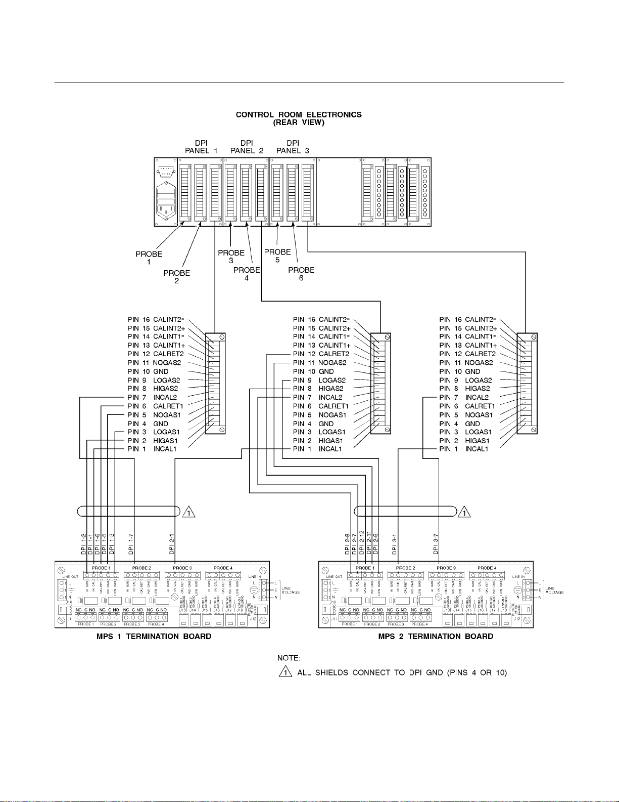
Instruction Manual
IB-106-300 NC Rev. 4.4
February 1998
World Class 3000
Figure 2-20. Typical CRE to MPS Connections, 5 or 6 Probes
2-22 Installation Rosemount Analytical Inc. A Division of Emerson Process Management
World Class 3000
2
Instruction Manual
IB-106-300NC Rev. 4.4
February 1998
b. Seven or Eight Probe Installation
(Figure 2-21)
1. Connect probes 1 and 2 to CRE DPI
panel 1, probes 3 and 4 to DPI panel 2,
probes 5 and 6 to DPI panel 3, and
probes 7 and 8 to DPI panel 4.
2. Connect DPI panel 1 to MPS number
1, probes 1 and 2, terminal blocks.
3. Connect DPI panel 2 to MPS number
1, probes 3 and 4, terminal blocks.
Table 2-4. Typical CRE SETUP Data for 7 or 8 Probe Configuration
SETUP - PROBE
Sub-Menu refer to
Table 3-6
CONFIGURE PROBES
PROBE____
INTERFACE
Interface Type
DPI Number
Unit Number
CALIBRATION
MPS Number
CONFIGURE MPS
MPS____
Control by PRB
Probe 1 Probe 2 Probe 3 Probe 4 Probe 5 Probe 6 Probe 7 Probe 8
DPI
1
1
1
1
DPI
1
2
1
1
Parameter Selection for
DPI
2
1
1
1
DPI
2
2
1
1
4. Connect DPI panel 3 to MPS number
2, probes 1 and 2, terminal blocks.
5. Connect DPI panel 4 to MPS number
2, probes 3 and 4, terminal blocks.
6. When entering the operator set variables, as listed in Table 3-6, SETUP
Sub-menu, enter the parameters for
DPI number, UNIT number, MPS number, and CONTROLLED BY PRB
number as indicated in Table 2-4.
DPI
3
1
2
5
DPI
3
2
2
5
DPI
4
1
2
5
DPI
4
2
2
5
Rosemount Analytical Inc. A Division of Emerson Process Management Installation 2-23

Instruction Manual
IB-106-300 NC Rev. 4.4
February 1998
World Class 3000
NOTE:
1
ALL SHIELDS CONNECT
TO DPI GND (PINS 4
OR 10)
PROBE
1
PROBE
2
PIN 16 CALINT2
PIN 15 CALINT2+
PIN 14 CALINT1
PIN 13 CALINT1+
PIN 12 CALRET2
PIN 11 NOGAS2
PIN 10 GND
PIN 9 LOGAS2
PIN 8 HIGAS2
PIN 7 INCAL2
PIN 6 CALRET1
PIN 5 NOGAS1
PIN 4 GND
PIN 3 LOGAS1
PIN 2 HIGAS1
PIN 1 INCAL1
DPI
PANEL 1
-
-
CONTROL ROOM ELECTRONICS
DPI
PANEL 2
PROBE
3
PROBE
4
(REAR VIEW)
DPI
PANEL 3
PROBE
5
PROBE
6
DPI
PANEL 4
PROBE 8
PROBE 7
PIN 16 CALINT2
PIN 15 CALINT2+
PIN 14 CALINT1
PIN 13 CALINT1+
PIN 12 CALRET2
PIN 11 NOGAS2
PIN 10 GND
PIN 9 LOGAS2
PIN 8 HIGAS2
PIN 7 INCAL2
PIN 6 CALRET1
PIN 5 NOGAS1
PIN 4 GND
PIN 3 LOGAS1
PIN 2 HIGAS1
PIN 1 INCAL1
-
-
PIN 16 CALINT2
-
PIN 15 CALINT2+
PIN 14 CALINT1
-
PIN 13 CALINT1+
PIN 12 CALRET2
PIN 11 NOGAS2
PIN 10 GND
PIN 9 LOGAS2
PIN 8 HIGAS2
PIN 7 INCAL2
PIN 6 CALRET1
PIN 5 NOGAS1
PIN 4 GND
PIN 3 LOGAS1
PIN 2 HIGAS1
PIN 1 INCAL1
1 1
LINE OUT LINE IN
L
T
S
L
A
E
A
C
R
G
L
I
A
IN
H
N
J10
J11
C
NC C NO NC CNO NC C NO NC C NO
PROBE 1
PROBE 2 PROBE 3 PROBE 4
L
T
S
S
S
A
E
A
A
A
C
R
G
G
G
O
N
L
I
A
IN
W
H
C
LO
S
S
S
A
A
A
G
G
G
I
O
W
H
N
LO
L
T
A
E
C
R
L
A
IN
C
J13 J14 J15 J16 J17 J18
L
T
S
S
A
A
G
G
O
W
N
LO
S
S
S
A
A
C
G
I
IN
H
L
E
A
A
R
G
G
L
O
A
W
N
C
LO
J12
PIN 16 CALINT2
PIN 15 CALINT2+
PIN 14 CALINT1
-
-
PIN 13 CALINT1+
PIN 12 CALRET2
PIN 11 NOGAS2
PIN 10 GND
PIN 9 LOGAS2
PIN 8 HIGAS2
PIN 7 INCAL2
PIN 6 CALRET1
PIN 5 NOGAS1
PIN 4 GND
PIN 3 LOGAS1
PIN 2 HIGAS1
PIN 1 INCAL1
L
LINE
E
VOLTAGE
N
N
LINE OUT LINE IN
L
T
S
L
A
E
A
C
R
G
L
I
A
IN
H
N
J10
J11
C
NC C NO NC CNO NC C NO NC C NO
PROBE 1
PROBE 2 PROBE 3 PROBE 4
L
T
S
S
S
A
E
A
A
A
C
R
G
G
G
O
N
L
I
A
IN
W
H
C
O
L
S
S
S
A
A
A
G
G
G
I
O
W
H
N
O
L
L
T
A
E
C
R
L
A
IN
C
J13 J14 J15 J16 J17 J18
L
T
S
S
A
A
G
G
O
W
N
O
L
S
S
S
A
E
A
A
A
C
R
G
G
G
L
I
O
A
IN
W
H
N
C
O
L
L
L
LINE
E
VOLTAGE
N
N
J12
MPS 2 TERMINATION BOARDMPS 1 TERMINATION BOARD
Figure 2-21. Typical CRE to MPS Connections, 7 or 8 Probes
2-24 Installation Rosemount Analytical Inc. A Division of Emerson Process Management

Instruction Manual
2
IB-106-300NC Rev. 4.4
World Class 3000
NOTE
!
Upon completing installation, make sure that the probe is turned on and operating prior to
firing up the combustion process. Damage can result from having a cold probe exposed to
the process gases.
During outages, and if possible, leave all probes running to prevent condensation and premature aging from thermal cycling.
If the ducts will be washed down during outage, MAKE SURE to power down the probes and
remove them from the wash area.
February 1998
Rosemount Analytical Inc. A Division of Emerson Process Management Installation 2-25

Instruction Manual
IB-106-300 NC Rev. 4.4
February 1998
World Class 3000
2-26 Installation Rosemount Analytical Inc. A Division of Emerson Process Management

World Class 3000
3
Instruction Manual
IB-106-300NC Rev. 4.4
February 1998
SECTION 3
OPERATION
3-1 OVERVIEW
Ensure that the oxygen analyzer, heater power
supply, and control room electronics have been
properly connected. It is important to check that
grounding and screening of terminations are
correctly made to prevent the introduction of
ground loops. The CRE is equipped with noise
suppression circuitry on the power supply and
signal input lines. Proper grounding at installation will ensure accuracy of function.
13
17
14
This section of the manual deals with operator
controls and displays available in the CRE. Operating parameters are listed and instructions
are included for viewing and changing them.
Any procedures not associated with normal operation are included in Section 2, Installation, or
Section 4, Troubleshooting.
3-2 FRONT PANEL CONTROLS AND
INDICATORS
12
3
5
4
6
8
1516
12
11
910
7
21200002
Figure 3-1. CRE Front Panel
Fig. 3-1
Index No. Control/LED
Description
1 HELP Context sensitive help is displayed when this key is pressed.
2 DATA DATA key is used to access data sub-menu.
3 LCD Display Top line is a status line which displays the current probe status, current menu
and current probe number. The second, third, and fourth lines display the
contents of the menu selected.
4 CAL CAL key used to access CALIBRATE O
sub-menu.
2
5 SETUP SETUP key used to access SETUP sub-menu.
6 RUN/PAR Keylock switch. RUN allows the operator to examine, but not modify, any
system parameter. Leave system in this mode except when changing
parameters. PAR allows parameter change and calibration.
Rosemount Analytical Inc. A Division of Emerson Process Management Operation 3-1

Instruction Manual
IB-106-300 NC Rev. 4.4
February 1998
Fig. 3-1 (Continued)
Index No. Control/LED
Description
7 ENTER The ENTER key is used to select a lower level menu, initiate calibration, or
select a parameter to change.
World Class 3000
8
▲
The increase key is used to move the cursor when scrolling through lists or to
increase a parameter value.
9
▼
The decrease key is used to move the cursor when scrolling through lists or to
decrease a parameter value.
10 ESC The escape key is used to exit to a high level menu or to abort a parameter
change.
11 AVERAGES LED Lights to indicate that O
averages have exceeded operator-set high and/or low
2
limits. Provided for up to four averages.
12 FAULT LED Lights to indicate fault condition. Provided for up to eight probes.
13 HIGH LED Lights to indicate that readings have risen above the high alarm limit. Provided
for up to eight probes.
14 LOW LED Lights to indicate that readings have fallen below the low alarm limit. Provided
for up to eight probes.
15 CAL LED Indicates analyzer is in calibrate mode. Provided for up to eight probes.
16 SYS. FAULT Indicates system fault condition.
LED
17 AUXILIARY Two lines of eight alphanumeric LEDs. Selectable to display O
readings of two
2
DISPLAY LED probes or user-specified averages.
3-3 STATUS LINE
g. LoO
. O
value is below the low alarm limit.
2
2
The top line of the LCD display (3, Figure 3-1) is
a status line that continuously displays current
h. R Hi. Cell resistance is above the high limit.
probe status, menu name, and current probe
selected. The probe status marked by an asterisk (*) will cause a fault condition and the fault
i. *Dable. Probe disabled, no longer calcu-
lated in the multiprobe averages.
LED to light.
a. OK. Current probe is functioning correctly.
b. CAL. Calibration in progress.
c. C Err. Calibration error.
j. *Off. Probe is turned off.
k. *Com-E. Communication error.
l. INACT. Interface for probe is not
configured.
d. *H Err. Probe heater temperature is out of
range (±5°C).
e. TGLow. Test gas is low.
f. HiO
. O
value is above the high alarm
2
2
limit.
3-2 Operation Rosemount Analytical Inc. A Division of Emerson Process Management
m. DPI E. CRE cannot communicate with
probe interface board.
n. PRB E. Probe is disconnected, cold, or
loads reversed.

World Class 3000
3
Instruction Manual
IB-106-300NC Rev. 4.4
February 1998
3-4 HELP KEY
The help key will display explanatory information about a menu, sub-menu, or parameter that
the asterisk is next to when pressed. The HELP
key is not available during calibration routines.
Refer to Table 3-1 for sample HELP messages.
Table 3-1. Sample HELP Messages
MENU, SUB-MENU,
HLP OR
PARAMETER NAME MESSAGE
DATA
PROBE DATA
VALUE
O
2
3-5 QUICK REFERENCE CHART
The quick reference chart, Figure 3-2, is designed to help you get to where you want to be
in the menu system. The chart shows all the
available menu and sub-menu options for the
CRE. Follow the lines to determine which menu
choices to make. To move down a level on the
chart, press the ENTER key. To move up a level
on the chart, press the ESCAPE key.
"The DATA menu displays
process data. Press ENTER
or the DATA key to access
the DATA menu."
"The PROBE DATA menu
displays information about a
single probe."
"This is an individual probe
percent O
value."
2
3-6 MAIN MENU
When power is first applied to the CRE, the
main menu is displayed under the status line.
The selections in the main menu are DATA,
CALIBRATE, and SETUP. These selections are
accessed by moving the cursor to the selection
and pressing the ENTER key, or pressing the
appropriate direct access button. Refer to Table
3-2.
Table 3-2. MAIN Menu
SUB-MENU DESCRIPTION
DATA
CALIBRATE
SETUP
3-7 DATA SUB-MENU
The DATA sub-menu (Table 3-3) can be viewed
but not changed. The DATA sub-menu is a list
of all the real time process data pertaining to the
system as it is currently configured. To access
the DATA sub-menu, press the DATA key on
the CRE front panel. There are three selections
available on the DATA sub-menu; SYSTEM
DATA, PROBE DATA, and SYSTEM STATUS.
The increase and decrease keys are used to
scroll through the list. The contents of the DATA
sub-menu are displayed on the second, third,
and fourth lines of the LCD display.
Refer to Table 3-3
Refer to Table 3-5
Refer to Table 3-6
Rosemount Analytical Inc. A Division of Emerson Process Management Operation 3-3

Instruction Manual
IB-106-300 NC Rev. 4.4
February 1998
World Class 3000
MAIN MENU
A
MULTIPROBE
AVERAGES
AVER 1
AVER 4
SYSTEM
DATA
O
2
VALUES
O
2
VALUE 1
O
2
VALUE8
EFFICIENCY
VALUES
EFF
VALUE 1
EFF
VALUE 8
DATA
PROBE
DATA
PROBE
STATUS
PROBE 1
PROBE 8
SYSTEM
STATUS
DIG O/P
STATUS
DIG O/P 1
DIG O/P 8
PERFORM
CALIBRATION*
AUTO MAN
ANALOG
O/P STATUS
A-OUT 1
A-OUT 2
CALIBRATE
VIEW
CONSTANTS
SLOPE
CONSTANT
CELL
RESIST
SOFTWARE
VERSION
CPU
DPI
CARD 1
DPI
CARD 4
CALIBRATION
STATUS
SLOPE
CONSTANT
CELL RESIST
PROCESS
DATA
VALUE
O
2
EFFICIENCY
STK TEMP
SELECTING PERFORM CALIBRATION WILL
*
RESULT IN AUTO OR MANUAL CAL BASED
ON VALUE SELECTED FOR PROBE IN PROBE
CAL SUB-MENU.
TEMPERATURES
DIAGNOSTIC
HTR TEMP
STK TEMP
CJ TEMP
DATA
VOLTAGES
CELL
HTR T/C
STK T/C
CJ T/C
Figure 3-2. Quick Reference Chart (Sheet 1 of 2)
3-4 Operation Rosemount Analytical Inc. A Division of Emerson Process Management

World Class 3000
3
A
SETUP
PROBESSYSTEM
Instruction Manual
IB-106-300NC Rev. 4.4
February 1998
AVERAGE
1 . . . 4
TIME AND
DATE
TIME
DATE
LED
DISPLAY
LINE 1
SRC
LINE 2
SRC
INTERFACE
ANALOG O/P
INTERF
TYPE
DPI
NUMBER
UNIT
NUMBER
1...12
SOURCE
RANGE
TYPE
CURRENT
PROBE
CURRENT
PROBE
1 . . . 8
DIGITAL O/P
1...8
GATE TYPE
GATE
INPUT 1
GATE
INPUT 16
ENABLE
PROBES
PROBE 1
ENABLED
PROBE 8
ENABLED
CALIBRATION
AUTO CAL
OUTPUT
TRACKS
MPS
NUMBER
CAL INTRVL
NEXT DATE
NEXT TIME
TEST GAS
TIME
PURGE TIME
RES ALARM
CONFIGURE
PROBES
O2ALARMS
HI ALARM
LO ALARM
DEADBAND
ALARMS
HIGH ALARM
LOW ALARM
DEADBAND
CONFIGURE
MPS
MPS 1...8
HIGH GAS
LOW GAS
CONTROLLED
BY PRB
O
CALCULATIONS
2
SLOPE
CONSTANT
SET POINT
LOAD
CONSTANTS
INPUTS
INPUTS
INPUT 1
INPUT 8
EFFICIENCY CALC
ENABLE CALC
K1 VALUE
K2 VALUE
K3 VALUE
Figure 3-2. Quick Reference Chart (Sheet 2 of 2)
Rosemount Analytical Inc. A Division of Emerson Process Management Operation 3-5

Instruction Manual
IB-106-300 NC Rev. 4.4
February 1998
Table 3-3. DATA Sub-Menu
ITEM IN SUB-MENU PARAMETER DESCRIPTION
SYSTEM DATA
World Class 3000
MULTIPROBE
AVERAGES
VALUES
O
2
EFFICIENCY VALUES
PROBE DATA
AVER 1 ____%
AVER 2 ____%
AVER 3 ____%
AVER 4 ____%
O
Value 1 ____%
2
O
Value 2 ____%
2
O
Value 3 ____%
2
O
Value 4 ____%
2
O
Value 5 ____%
2
O
Value 6 ____%
2
Value 7 ____%
O
2
O
Value 8 ____%
2
Eff Value 1 ____%
Eff Value 2 ____%
Eff Value 3 ____%
Eff Value 4 ____%
Eff Value 5 ____%
Eff Value 6 ____%
Eff Value 7 ____%
Eff Value 8 ____%
Average 1 value
Average 2 value
Average 3 value
Average 4 value
O
value for each probe configured
2
Efficiency value for each probe configured for efficiency
PROCESS DATA
Value ____%
O
2
Efficiency ____%
Stk Temp ____DegC
O
value for the probe selected
2
Efficiency value for the probe selected (when enabled)
Stack temperature for the probe selected, (when efficiency is enabled)
DIAGNOSTIC DATA
TEMPERATURES
Htr Temp ____DegC
Stk Temp ____DegC
CJ Temp ____DegC
VOLTAGES
Cell ____mV
Htr T/C ____mV
Stk T/C ____mV
CJ T/C ____mV
3-6 Operation Rosemount Analytical Inc. A Division of Emerson Process Management
Cell temperature of the probe selected
Stack temperature of the probe selected
Cold junction temperature of the probe selected
Cell voltage of the probe selected
Cell thermocouple voltage of the probe selected
Stack thermocouple voltage of the probe selected
Cold junction voltage of the probe selected

World Class 3000
3
Table 3-3. DATA Sub-Menu (Continued)
ITEM IN SUB-MENU PARAMETER DESCRIPTION
SYSTEM STATUS
Instruction Manual
IB-106-300NC Rev. 4.4
February 1998
PROBE STATUS
DIG O/P STATUS
ANALOG O/P
STATUS
SOFTWARE
VERSION
PROBE 1 ____
PROBE 2 ____
PROBE 3 ____
PROBE 4 ____
PROBE 5 ____
PROBE 6 ____
PROBE 7 ____
PROBE 8 ____
DIG OP 1 ____
DIG OP 2 ____
DIG OP 3 ____
DIG OP 4 ____
DIG OP 5 ____
DIG OP 6 ____
DIG OP 7 ____
DIG OP 8 ____
A-Out 1 ____%
A-Out 2 ____%
A-Out 3 ____%
A-Out 4 ____%
A-Out 5 ____%
A-Out 6 ____%
A-Out 7 ____%
A-Out 8 ____%
A-Out 9 ____%
A-Out 10 ____%
A-Out 11 ____%
A-Out 12 ____%
CPU 1.0
DPI CARD 1 1.3
DPI CARD 2 1.3
DPI CARD 3 1.3
DPI CARD 4 INACT
The status of the probes will be one of the following:
OK - Functioning correctly
HIO
- Above high O2 limit
2
LOWO
INACT - Probe is not in system
CAL - Probe is being calibrated
The status of the digital outputs will be one of the following:
ON - Digital output is actuated
OFF - Digital output is not actuated
INACT - Digital output is not configured
Value for each analog output
Software version of CPU card
Software version of DPI 1
Software version of DPI 2
Software version of DPI 3
System does not have DPI 4
- Below low O2 limit
2
Rosemount Analytical Inc. A Division of Emerson Process Management Operation 3-7

Instruction Manual
IB-106-300 NC Rev. 4.4
February 1998
World Class 3000
3-8 CALIBRATE SUB-MENU
The CALIBRATE sub-menu is used to enter the
calibration mode. To access the CALIBRATE
sub-menu, press the CAL key on the CRE key
on the CRE front panel. The increase and decrease keys are used to scroll through the list.
At the beginning of the PERFORM CALIBRATION procedure, an error message may be displayed. Unless the error is corrected,
PERFORM CALIBRATION will not continue.
Refer to Table 3-4 for the error messages.
The CALIBRATE sub-menu has three items
available: PERFORM CALIBRATION, VIEW
CONSTANTS, and CALIBRATION STATUS.
Refer to Table 3-5 for contents of the submenus.
To abort a calibration in progress during PERFORM CALIBRATION, press the ESC key.
Table 3-4. Perform Calibration Error Messages
Error Messages Remedy
3-9 USING THE SETUP SUB-MENU
The SETUP sub-menu (Table 3-6) is used to
enter all operator set variables into the system.
To access the SETUP sub-menu, press the
SETUP key on the CRE front panel. There are
items available on the SETUP sub-menu; SYSTEM, PROBE, and AVERAGE. To select a parameter in a sub-menu to be changed, move the
cursor to the desired parameter using the arrow
keys. Press ENTER to select that parameter. To
change the value for that parameter, use the arrow keys to increase or decrease the value.
Press ENTER to save changes.
NOTE
Parameters can only be changed with
the RUN/PAR keylock (6, Figure 3-1) in
the PAR position.
Key required for calibration
Test gas low, can't calibrate
Heater error, can't calibrate
Turn keylock switch to the PAR position
Check test gas bottles connected to the MPS
Wait for heater to stabilize before calibrating
3-8 Operation Rosemount Analytical Inc. A Division of Emerson Process Management

World Class 3000
3
Instruction Manual
IB-106-300NC Rev. 4.4
February 1998
Table 3-5. CALIBRATE Sub-Menu
SUB-MENU
SELECTION
Perform
Calibration
SETUP SETTING
(SEE TABLE 3-4) DATA QUEUES DESCRIPTION
Auto Cal in Probe
Setup is YES
Press ENTER to start Auto
calibration.
The MPS under control of the CRE will
begin a fully automatic calibration on the
probe selected.
1. "Waiting for MPS to
become available"
2. "Starting Automatic
Calibration"
3. High Gas ____%O
Time Left 0:00
Value ____%O
O
2
4. Low Gas ____%O
Time Left 0:00
Value ____%O
O
2
5. Resistance Check
2
2
2
2
If MPS is in use, calibration will not begin
until available.
After ENTER is pressed, five data queues
appear consecutively.
Value for high O
Gas time runs down in min:sec
Value for O
2
Value for low O2 test gas
Gas time runs down in min:sec
Value for O
2
Resistance check in progress
Time runs down in min:sec
System is purged.
Semiautomatic calibration routine begins.
Manually turn on the high O
Press ENTER to continue.
Auto Cal in Probe
Setup is NO.
6. Returning to Process
Press ENTER to start Manual Calibration
Switch on high test gas.
Press ENTER when ready.
test gas
2
test gas.
2
View
Constants
Calibration
Status
High O2 value ____%O
Press ENTER when ready.
Switch from HIGH to LOW
test gas.
Press ENTER when ready.
Low O
value ____%O
2
Press ENTER when ready.
Resistance Check - wait
Time Left 0:00
Switch off LOW test gas.
Press ENTER when ready.
value ____%O
O
2
Press ENTER when probe
has returned.
(N/A) Slope ____mV/D
Constant ____mV
Cell Resist ____ohms
(N/A) Slope ____
Constant ____
Cell Resist ____
2
High O2 value.
Press ENTER when O
reading stabilizes.
2
Manually turn off the high O
turn on the low O
test gas.
2
test gas and
2
Press ENTER to continue.
2
Low O
Press ENTER when O
value.
2
reading stabilizes.
2
Resistance check in progress.
Time runs down in min:sec.
Manually turn off the low test gas.
2
Semiautomatic calibration is complete for
the probe selected.
Slope for probe selected.
Offset for probe selected.
Resistance for probe selected.
Status of the slope.
Status of the offset.
Status of the resistance.
Rosemount Analytical Inc. A Division of Emerson Process Management Operation 3-9

Instruction Manual
IB-106-300 NC Rev. 4.4
February 1998
Table 3-6. SETUP Sub-Menu
ITEM IN SUB-MENU DISPLAY SELECTABLE OPTIONS
TIME & DATE
TIME
DATE
XX:XX
DDMMYY
Hours 1-23; Minutes 1-59
Day, Month, Year
World Class 3000
LED DISPLAY
ANALOG OUTPUTS
*ANALOG O/P 1
DIGITAL OUTPUTS
**DIG O/P 1
GATE TYPE
GATE INPUTS
LINE 1 SRC ______
LINE 2 SRC ______
SOURCE ______
RANGE __-___%
TYPE __-___mA
OR or NOR
INPUT 1 _______
INPUT 2 _______
INPUT 3 _______
INPUT 4 _______
INPUT 5 _______
INPUT 6 _______
INPUT 7 _______
INPUT 8 _______
INPUT 9 _______
INPUT 10 _______
INPUT 11 _______
INPUT 12 _______
INPUT 13 _______
INPUT 14 _______
INPUT 15 _______
INPUT 16 _______
Sources for the auxiliary LED displays can be one
of the following: AVG 1-4, PRB 1-8, or date and
time
Source can be one of the following: AVG 1-4,
PRB 1-8
Range can be one of the following: 0-1%, 0-5%,
0-10%, 0-25%, or 0-100%
Type can be either 0-20 mA, or 4-20 mA
Non-inverted or inverted
Data input can be one of the following:
INACTIVE, SYS FAULT
AV 1-4; HIGH or LOW
PR 1-8; HIGH, LOW, CAL, FAIL, TG, or CAL E
PROBES
CURRENT PROBE
ENABLE PROBES
CONFIGURE PROBES
**PROBE 1
*Format is repeated for number of probes configured in system.
**Format is repeated for all eight probes.
3-10 Operation Rosemount Analytical Inc. A Division of Emerson Process Management
CURRENT PROBE _____
*PRB 1 ENABLED _____
Select configured probe number 1-8 for LCD
display.
Select YES to enable, NO to disable, or OFF to
turn off HPS (parameter is "OFF" when probe is
initially configured).
NOTE
Relay in HPS must be wired to the CRE.
Select probe to be configured, 1-8.
World Class 3000
3
Table 3-6. SETUP Sub-Menu (Continued)
ITEM IN SUB-MENU PARAMETER SELECTABLE OPTION
PROBES (Continued)
NOTE
Once the probe is selected, the following five items are available.
Instruction Manual
IB-106-300NC Rev. 4.4
February 1998
INTERFACE
CALIBRATION
O
ALARMS
2
O
2
CALCULATION
INTERF Type ______
DPI Number ______
UNIT Number ______
Auto Cal YES/NO
Output Tracks YES/NO
MPS Number ______
Cal. Intrvl X
Next Date ______
Next Time ______
Test Gas Time 0:00
Select type of probe interface.
Select interface address.
Select unit number.
If the system has an MPS, select YES, otherwise NO.
Select output tracks.
Select which MPS the probe is connected to.
Select time between calibrations in # of days.
Date of next calibration.
Displays time of next calibration in hours and minutes.
Amount of time for test gases to be turned on in
minutes and seconds, allow enough time for signal
value to stabilize
Purge Time 0:00
Amount of time for the gas lines to clear of test gas
(Return to process).
Res Alarm ______
Hi Alarm ______% O
Low Alarm ______% O
Deadband ______% O
Slope ______mV/D
Constant ______mV
Resistance alarm set from 50-10000 ohms.
Set value for high alarm limit.
2
Set value for low alarm limit.
2
Set value for alarm deadband.
2
Set value between 34.5 and 57.5 mV/DECADE.
Set value between -20.0 and 20.0 mV.
Ensure the correct voltage is selected when using HPS 3000 with
218 probes. Refer to Figure 2-15, Jumper Selection Label for
proper voltage selection. If incorrect SET POINT is selected,
damage to the probe may occur.
Set Point ______°C
Set either 736 for World Class 3000 probes or 843 for
218 probes.
EFFICIENCY
CALC.
CONFIGURE MPS
***MPS 1
Load Constants
ENABLE CALC YES/NO
K1 Value _____
K2 Value _____
K3 Value _____
High Gas ______%O
Low Gas ______%O
Controlled by Prb _____
Press ENTER to load constants from last calibration.
Select YES to enable, NO to disable.
Set between 0.0000 and 1.0. (Refer to Table 3-7)
Set between 0.0000 and 1.0. (Refer to Table 3-7)
Set between 1.000 and 20.0. (Refer to Table 3-7)
Select the MPS unit to be configured (1 - 8).
Value of high O
2
Value of low O
2
test gas.
2
test gas.
2
Select probe number wired to MPS.
**All eight probes are displayed.
Rosemount Analytical Inc. A Division of Emerson Process Management Operation 3-11

Instruction Manual
IB-106-300 NC Rev. 4.4
February 1998
Table 3-6. SETUP Sub-Menu (Continued)
ITEM IN SUB-MENU DISPLAY SELECTABLE OPTIONS
AVERAGE
****AVERAGE 1
ALARMS
HIGH ALARM ______
LOW ALARM ______
DEADBAND ______
Select the average to be setup for all four averages
Set the value for high alarm.
Set the value for low alarm.
Set the value for deadband.
World Class 3000
INPUTS
***Format is repeated for each MPS selected (up to 8 selectable).
****All four averages are displayed.
CONSTANT
K1
K2
K3
3-10 CALIBRATION
a. Overview
The primary purpose of an oxygen analyzer
is to give an accurate representation of the
percentage of O
system should be calibrated periodically to
maintain an accuracy which may otherwise
reduce over time due to cell aging.
A requirement for calibration is a set of two
accurate test gases spanning the oxygen
range of most interest. For example, 0.4%
and 8% for a 0-10% oxygen range.
Under normal conditions the probe should
not need frequent calibration. Because calibration is necessary, the system can be
equipped with the optional MPS 3000 Multi-
INPUT 1 ______
INPUT 2 ______
INPUT 3 ______
INPUT 4 ______
INPUT 5 ______
INPUT 6 ______
INPUT 7 ______
INPUT 8 ______
Table 3-7. Efficiency Constants.
UNITED STATES EUROPE
GAS OIL GAS OIL
0.407
0.0
5.12
in the gas stream. The
2
Set the probe number to any possible configured
probe or to Inact. (Same for all eight inputs.)
0.432
0.0
5.12
probe Test Gas Sequencer for fully automatic calibration at regular intervals.
Without an MPS, the probes must be calibrated manually (semiautomatically).
b. Probe Calibration
There are three calibration methods: manual (semiautomatic), manually initiated
automatic, and fully automatic. Manual
(semiautomatic) calibration is done without
an MPS unit. Test gases are switched on
and off by the operator and the CRE is sequenced through the calibration procedure
by the operator with the front panel keyboard. The CRE prompts the operator for
the correct action. Manually initiated automatic calibration is done with an MPS. The
operator manually initiates the calibration at
0.66
0.0082
12.28
0.69
0.0051
8.74
3-12 Operation Rosemount Analytical Inc. A Division of Emerson Process Management
World Class 3000
3
Instruction Manual
IB-106-300NC Rev. 4.4
February 1998
the CRE or through a remote switch, and
the CRE controls the operation of the
MPS unit and the calibration sequencing.
Fully automatic calibration requires no action from the operator. The setup is the
same as semiautomatic except the CRE
automatically initiates the calibration at a
fixed calibration interval. In this mode the
operator can also manually initiate calibrations between the intervals in the same
manner as semiautomatic calibrations.
c. Manual (Semiautomatic) Calibration.
1. Test Gases For Manual (Semiautomatic) Calibration. There are two op-
tions for supplying test gases to the
probe during semiautomatic calibration.
The first, "A", uses refillable bottles and
adjustable 2-stage pressure regulators;
the second, "B", uses disposable bottles and a fixed single stage regulator
to provide a mixed flow. Normally, the
first ("A") will have a higher cost and
not be portable. The second ("B") is
less costly and portable, because it
only weighs about 10 pounds (4,5 kg).
Test Method "A" Fixed Tanks and
Manifolds.
(a) Required Equipment.
Two sources of calibrated gas
mixtures are:
LIQUID CARBONIC
GAS CORP.
SPECIALTY GAS
LABORATORIES
700 South Alameda Street
Los Angeles, California
90058
213/585-2154
767 Industrial Road
San Carlos, California 94070
415/592-7303
9950 Chemical Road
Pasadena, Texas 77507
713/474-4141
12054 S.W. Doty Avenue
Chicago, Illinois 60628
312/568-8840
603 Bergen Street
Harrison, New Jersey 07029
201/485-1995
255 Brimley Road
Scarborough, Ontario,
Canada
416/266-3161
SCOTT ENVIRONMENTAL
TECHNOLOGY, INC.
Do not use 100% nitrogen as a zero
gas. It is suggested that gas for the
zero be between 0.4% and 2.0% O2. Do
not use gases with hydrocarbon concentrations of more than 40 parts per
million. Failure to use proper gases
will result in erroneous readings.
NOTE
Ambient air is not recommended for
use as high test gas. An 8% O
ance in nitrogen is recommended for
high test gas.
1 Two tanks of precision cali-
bration gas mixtures. Recommended calibration gases
are nominally 0.4% and 8.0%
oxygen in nitrogen.
Rosemount Analytical Inc. A Division of Emerson Process Management Operation 3-13
bal-
2
SCOTT SPECIALTY
GASES
2600 Cajon Blvd.
San Bernardino, CA 92411
714/887-2571
TWX: 910-390-1159
1290 Combermere Street
Troy, MI 48084
314/589-2950
Route 611
Plumsteadville, PA 18949
215/766-8861
TWX: 510-665-9344
2616 South Loop West,
Suite 100
Houston, TX 77054
713/669-0469

Instruction Manual
IB-106-300 NC Rev. 4.4
February 1998
World Class 3000
2 If gas bottles will be perma-
nently hooked up to the probe,
a manual block valve is required at the probe (between
the calibration fitting and the
gas line) to prevent the migration of process gases down
the calibration gas line.
3 If an MPS 3000 Multiprobe
Gas Sequencer is used, a
check valve is required at the
probe.
4 Two, 2-stage pressure regu-
lators with stainless steel diaphragms for tanks. Maximum
output required: 20 psi (138
kPa).
5 One instrument air pressure
regulator: 20 psi (138 kPa)
maximum and a supply of
clean, dry instrument air.
6 Two zero-leakage shutoff
valves.
7 Miscellaneous oil-free tubing
and fittings.
(b) Calibration.
For optimum accuracy, this calibration
should be run with the process at
normal temperature and operating
conditions.
1 A typical calibration setup is
shown in Figure 3-3. Care
must be taken that all fittings
are tight and free from oil or
other organic contaminants.
Small openings can cause
back diffusion of oxygen from
the atmosphere even though
positive pressures are maintained in the lines.
NOTE
The probe calibration gas fitting has a
seal cap which must be in place at all
times except during calibration.
In addition to the precision
calibration gas mixtures,
clean, dry, oil-free instrument
air should be used for
calibration.
PROBE
(END VIEW)
CALIBRATE
IN-PLACE
FITTING
FLOW METER
LEAK TIGHT
VALVES
REG
5 SCFH
0.4%
O
2
CHECK
VALVE
REFERENCE AIR
CONNECTION
8.0%
O
2
NOTE:
2 SCFH
REFERENCE
AIR SET
INSTR.
AIR IN
PROBE CALIBRATION GAS FITTING HAS A
SEAL CAP WHICH MUST BE IN PLACE AT
ALL TIMES EXCEPT DURING CALIBRATION.
Figure 3-3. Typical Calibration Setup
3-14 Operation Rosemount Analytical Inc. A Division of Emerson Process Management

World Class 3000
3
Instruction Manual
IB-106-300NC Rev. 4.4
February 1998
When the calibration gas line
exceeds 6 feet (1,8 m) in
length from the leak tight
valves, a check valve, Rosemount P/N 6292A97H02,
should be installed next to the
calibration gas connection on
the probe to prevent breathing
of the line with the process
gas and subsequent gas condensation and corrosion.
NOTE
Only set the test gas flowmeter upon
initial installation and after changing
the diffusion element. A slightly lower
test gas flow rate may indicate a
plugged diffusion element.
2 Set the test gas pressure
regulators and the flow meter
for a flow of 5 SCFH at 20 psi
(138 kPa) for both gases. The
reference gas should be
flowing as in normal
operation.
NOTE
Ambient air is not recommended for
use as high test gas. An 8% O
bal-
2
ance in nitrogen is recommended for
high test gas.
1 Portable Rosemount Oxygen
Test Gas Kits (Figure 3-4),
Rosemount P/N 6296A27G01,
containing 8% and 0.4%
gases in a portable carrying
case with regulator, built-in
valve, hose and connecting
adapter to the calibration gas
connection.
3 Refer to paragraph 2 of this
section for Manual (Semiautomatic) Calibration setup and
procedure using the CRE.
4 Test gases will be switched on
and off using the shutoff
valves.
Test Method "B" Rosemount Oxygen Test Gas and Service Kit.
(a) Required Equipment.
Do not use 100% nitrogen as a zero
gas. It is suggested that gas for the
zero be between 0.4% and 2.0% O2. Do
not use gases with hydrocarbon concentrations of more than 40 parts per
million. Failure to use proper gases
will result in erroneous readings.
TEST GAS
(P/N 6296A27G01)
KIT #1
Figure 3-4. Portable Rosemount Oxygen
Test Gas Kit
629100
Rosemount Analytical Inc. A Division of Emerson Process Management Operation 3-15

Instruction Manual
IB-106-300 NC Rev. 4.4
February 1998
2 Extra gas bottles are available
at:
Rosemount Analytical Inc.
Box 901
Orrville, Ohio 44667
U.S.A.
Rosemount Limited
Burymead Road
Hitchin, Herts. U.K.
Rosemount Italy
VIA Guido Cavalcanti 8
20127 Milan, Italy
Rosemount Spain
Saturnino Calleja 6
28002 Madrid
Spain
World Class 3000
CALIBRATE IN
NOTE:
PLACE
CONNECTION
CHECK
VALVE
PUSHBUTTON
REGULATOR
WITH CONTENTS
GAGE - SET 5 SCFH
PROBE CALIBRATION GAS
FITTING HAS A SEAL CAP
WHICH MUST BE IN PLACE
EXCEPT DURING CALIBRATION.
Figure 3-5. Typical Portable Test
Calibration Setup
REFERENCE AIR
CONNECTION
TEST HOSE
CONNECTS
TO CHECK
VALVE
0.4
%
O
2
8.0
%
O
2
19270009
Rosemount France
165 Boulevard de Vallmy
92706, Colombes, France
Rosemount P/N 3530B07G01
for probe 0.4% oxygen in nitrogen in disposable bottle.
Rosemount P/N 3530B07G02
for probe 8% oxygen in nitrogen in disposable bottle.
3 A check valve or manual block
valve is required at the probe
(between the calibration fitting
and the gas line) to prevent
the migration of process
gases down the calibration
gas line.
(b) Calibration with a Portable Rose-
mount Oxygen Test Gases Kit.
1 A typical portable test calibra-
tion setup is shown in Figure
3-5. For Manual (semiautomatic) calibration, remove cap
plug from the calibrate in
place fitting. The cap plug
must be retained to seal this
fitting after calibration is complete; failure to do so may
render the probe useless if the
system pressure is slightly
negative. The reference gas
should be flowing as in normal
operation.
2 Refer to paragraph 2 of this
section for Manual (Semiautomatic) Calibration setup and
procedure using the CRE.
3 Screw the pushbutton regu-
lator with contents gage on to
the test gas of choice and inject the test gas by opening
the valve. Gas is on continuously when the valve is
opened.
2. Manual (Semiautomatic) Calibration
Procedure. The calibration is manually
performed by the operator upon data
queues from the CRE. Any system
without an MPS 3000 Multiprobe Test
Gas Sequencer must follow these
steps.
In order for the system to calibrate
manually, the following parameters
from the Cal_Cfg menu have to be
entered. This menu can be reached
from the top level SETUP sub-menu by
making the following selections:
Probes; Configure Probes; Probe N;
Calibration. Refer to Table 3-6, SETUP
Sub-menu.
3-16 Operation Rosemount Analytical Inc. A Division of Emerson Process Management

World Class 3000
3
Instruction Manual
IB-106-300NC Rev. 4.4
February 1998
AutoCal
YES/NO
Output
Tracks
MPS
Number
Cal Intrvl
Next Date
Next Time
Test Gas
Time
Purge Time
Res Alarm _____ Set the desired resis-
The following parameters from the MPS_Cfg menu
must entered. This menu can be reached from the
top level SETUP sub-menu by making the following
selections: Probes; Configure MPS; MPS N. Refer to
Table 3-6, SETUP Sub-menu.
High Gas
Set to NO
YES/NO Set as desired.
N
DDD
DDMMMYY
HH:MM
0:00
0:00
X.XXXX%
Set the desired MPS
number. Even though
an MPS is not being
used, the test gas values from this MPS will
be used for calibrating
this probe. Any other
probe using these
same test gas values
should reference this
same MPS.
The calibration interval
time does not apply to
manual calibrations.
The next calibration
time does not apply to
manual calibrations.
The next calibration
date does not apply to
manual calibrations.
The test gas time does
not apply to manual
calibrations.
The purge time does
not apply to manual
calibrations.
tance alarm between
50 to 10000 ohms.
Set the value of the
high test gas bottle.
Once these parameters have been
set, the operator will be guided
through a manual calibration as
follows:
1 Select the probe to be cali-
brated by setting the Current
Probe parameter in the
Prb_Set menu. This menu
can be reached from the top
level SETUP sub-menu by
making the following selections: Probes. Refer to Table
3-6, SETUP Sub-menu.
2 Start the calibration procedure
by selecting Perform Calibration from the Prb_Cal menu.
This menu is the top level
CAL menu. The LCD display
will read Press ENTER to start
Manual Calibration. Press
ENTER to start. Follow the
data queues. Refer to Table
3-5, CALIBRATE Sub-menu
(AUTO CAL in PROBE
SETUP is NO) for a list of the
data queues.
d. Fully Automatic Calibration
1. Test Gases for Fully Automatic Calibration. For fully automatic calibra-
tion, an MPS 3000 Multiprobe Test
Gas Sequencer is required as well as
the two types of test gas.
Do not use 100% nitrogen as a zero
gas. It is suggested that gas for the
zero be between 0.4% and 2.0% O2. Do
not use gases with hydrocarbon concentrations of more than 40 parts per
million. Failure to use proper gases
will result in erroneous readings.
Low Gas
Controlled
by Prb
Rosemount Analytical Inc. A Division of Emerson Process Management Operation 3-17
X.XXXX%
N
Set the value of the low
test gas bottle.
Enter a value of 0.
NOTE
Ambient air is not recommended for
use as high test gas. An 8% O
ance in nitrogen is recommended for
high test gas.
bal-
2

Instruction Manual
IB-106-300 NC Rev. 4.4
February 1998
World Class 3000
(a) Two tanks of precision calibration
gas mixtures. Recommended calibration gases are nominally 0.4%
and 8.0% oxygen in nitrogen.
(b) An MPS 3000 properly connected
to the probe and the CRE. Refer
(END VIEW)
CHECK
TEST GAS
VALVE
PROBE
REFERENCE
HPS
MPS-CRE
SIGNAL
CONNECTIONS
AIR
PROBE
SIGNAL CONNECTIONS
to paragraph 2-4, Multiprobe Test
Gas Sequencer Installation.
A typical automatic calibration system
is shown in Figure 3-6.
CRE
MPS
INSTRUMENT
AIR IN
NOTES: THE MPS CAN BE USED WITH UP TO
FOUR PROBES. ONLY ONE PROBE CAN
BE CALIBRATED AT A TIME. PROBE
CALIBRATIONS MUST BE SCHEDULED
IN MULTIPLE PROBE APPLICATIONS.
SHOWN WITH HPS OPTION.
Figure 3-6. Typical Automatic Calibration System
TEST GAS 1
(HIGH O
)
2
TEST GAS 2
(LOW O2)
3-18 Operation Rosemount Analytical Inc. A Division of Emerson Process Management

World Class 3000
3
Instruction Manual
IB-106-300NC Rev. 4.4
February 1998
2. Fully Automatic Calibration Setup.
The calibration is fully controlled by the
CRE 3000 system using an MPS 3000
Multiprobe Test Gas Sequencer to
control the application of test gas.
In order for the system to calibrate
automatically, the following parameters
from the Cal_Cfg menu have to be
entered. This menu can be reached
from the top level SETUP sub-menu by
making the following selections:
Probes; Configure Probes; Probe N;
Calibration. Refer to Table 3-6, SETUP
Sub-menu.
Auto Cal YES/NO Set to YES
Output
Tracks
MPS
Number
Cal Intrvl DDD Set the calibration in-
Next Date DDMMMYY Set the date for the
Next Time HH:MM Set the time of the
Gas Time 0:00 Set the amount of time
Purge Time 0:00 Set the amount of time
Res Alarm ____ Set the desired resis-
YES/NO Set as desired.
N Set the desired MPS
number.
terval in days. If automatic initiation of
calibrations is not desired, this value should
be decreased under 1
to DISABLED.
next automatic calibration.
next automatic calibration.
for the test gases to be
turned on in seconds,
allow enough time for
signal value to stabilize.
for the gas lines to
clear (probe returns to
process) in number of
minutes and seconds.
tance alarm between
50 to 10000 ohms.
The following parameters form the MPS_Cfg menu
must be entered. This menu can be reached from
the top level SETUP sub-menu by making the following selections: Probes; Configure MPS’ MPS N.
Refer to Table 3-6, Setup Submenu.
High Gas X.XXXX% Set the value of the
high test gas bottle.
Low Gas X.XXXX% Set the value of the
low test gas bottle.
Controlled
by Prb
N Enter the number of
the probe that is
wired to the MPS for
high and low test
gas control. Refer to
paragraph 2-4, Multiprobe Test Gas
Sequencer
Installation.
Once these parameters have been set,
the system will initiate calibration without operator intervention as set by the
CAL INTVL parameter.
3. Manually Initiated Fully Automatic
Calibration Procedure. The following
procedure relates to an operator initiated calibration, either by a remote
switch or selected at the CRE by
pressing the CAL key using an MPS
3000 Multiprobe Gas Sequencer.
(a) Select the probe to be calibrated
by setting the Current Probe parameter in the Prb_Set menu. This
menu can be reached from the top
level SETUP sub-menu by making
the following selection: Probes.
Refer to Table 3-6, SETUP Submenu.
(b) Start the calibration procedure by
selecting Perform Calibration from
the Prb_Cal menu. This menu is
the top level CAL menu. Press
ENTER to start AUTO; Calibration
will appear on the LCD display.
Press ENTER to start. Follow the
data queues. Refer to Table 3-5,
CALIBRATE Sub-menu for a list of
the data queues that will appear.
Rosemount Analytical Inc. A Division of Emerson Process Management Operation 3-19

Instruction Manual
IB-106-300 NC Rev. 4.4
February 1998
World Class 3000
3-20 Operation Rosemount Analytical Inc. A Division of Emerson Process Management
World Class 3000
4
Instruction Manual
IB-106-300NC Rev. 4.4
February 1998
SECTION 4
TROUBLESHOOTING
4-1 OVERVIEW
The system troubleshooting section describes
how to identify and isolate faults which may develop in the oxygen analyzer system. Refer to
Probe, IFT, HPS, and MPS Appendices.
4-2 SPECIAL TROUBLESHOOTING NOTES
Install all protective equipment covers
and safety ground leads after troubleshooting. Failure to replace covers
and ground leads could result in serious injury or death.
a. Grounding
It is essential that adequate grounding precautions are taken when the system is being installed. A very thorough check must
be made at both the probe and electronics
to ensure that the grounding quality has not
degraded during fault finding. The system
provides facilities for 100% effective
grounding and the total elimination of
ground loops.
b. Electrical Noise
c. Loose Integrated Circuits
The CRE uses a microprocessor and supporting integrated circuits. Should the electronics unit receive rough handling during
installation in a location where it is subjected to severe vibration, an Integrated
Circuit (IC) could work loose. The fault finding guide, Table 4-1, shows the resulting
variety of failure modes. It is recommended
that all IC's be confirmed to be fully seated
before troubleshooting on the system begins.
d. Electrostatic Discharge
Electrostatic discharge can damage the IC's
used in the electronics unit. It is essential
before removing or handling the processor
board or the IC's used on it, that the user
ensure he/she is at ground potential.
4-3 PROBE TROUBLESHOOTING
a. Probe Faults
Listed below are the three symptoms of
probe failure.
1. The system does not respond to
changes in the oxygen concentration.
The CRE has been designed to operate in
the type of environment normally found in a
boiler room or control room. Noise suppression circuits are employed on all field terminations and main inputs. When fault finding,
the electrical noise being generated in the
immediate circuitry of a faulty system should
be evaluated.
b. Table 4-1 provides a guide to fault finding
Rosemount Analytical Inc. A Division of Emerson Process Management Troubleshooting 4-1
2. The system does respond to oxygen
changes, but does not give the correct
indication.
3. The system does not give an acceptable indication of the value of the oxygen test gas being applied during
calibration.
for the above symptoms.

Instruction Manual
IB-106-300 NC Rev. 4.4
February 1998
Table 4-1. Fault Finding
SYMPTOM CHECK FAULT REMEDY
1. No response to
oxygen concentration change
when:
World Class 3000
Heater is cold
and TC mV output is less than
set point
Heater is hot
and T/C mV output is at set point
+0.2 mV
2. System responds to
oxygen concentration changes,
but does not
give correct
indication
Thermocouple continuity
Heater cold resistance to
be 11 ohm to 14 ohm
Triac O/P to heater
Recorder chart
Cell mV input to electronics and cell mV at
probe head
Recorder or remote
indicator
Thermocouple failure
Heater failure
Failure of electronics
Recorder failure
No cell mV at probe
Probe cell mV OK, but
no input to electronics
Cell MV satisfactory
both at probe head and
input to electronics failure of electronics
Calibration error
Replace thermocouple or return probe to Rosemount.
Replace heater or return probe
to Rosemount.
Replace faulty DPI board or
HPS. Configure jumpers on
new board. See Table 2-2, DPI
Card Jumper Configuration.
See Recorder Instruction
Manual.
Replace cell or return probe to
Rosemount.
Check out cable connection.
Replace faulty DPI board.
Configure jumpers on new
board. See Table 2-2, DPI
Card Jumper Configuration.
Recalibrate recorder or indicator Reference Recorder Instruction Manual.
Good response
with incorrect
indication
4-2 Troubleshooting Rosemount Analytical Inc. A Division of Emerson Process Management
System calibration
Probe mounting and
condition of duct
Cell mV input to electronics
Calibration error
Air ingress into duct
Failure of electronics
Recalibrate system.
Stop air leaks or resite probe.
Replace faulty DPI board.
Configure jumpers on new
board. See Table 2-2, DPI
Card Jumper Configuration.

World Class 3000
4
Table 4-1. Fault Finding (Continued).
SYMPTOM CHECK FAULT REMEDY
Instruction Manual
IB-106-300NC Rev. 4.4
February 1998
3. System does
not give accurate indication
of applied test
Test gas input port
Ceramic diffusion element
gas
4-4 CRE ALARM MESSAGES
The CRE status line which is located on the top
line of the LCD display may have one of the
following alarm messages. The alarm message
area is in the upper left corner of the LCD. The
message pertains to the current probe which is
indicated by the probe number in the upper right
corner of the LCD display.
a. *DPI E
The CRE cannot communicate with the
probe interface board. Check the probe
configuration and probe interface board's
jumper configuration or replace the faulty
interface board.
b. *Cal E
Blocked port
Diffusion element
cracked, broken, or
missing
e. HiO
The O2 reading for this probe is above the
high alarm limit.
f. LoO
The O2 reading for this probe is below the
low alarm limit.
g. R Hi
The cell resistance measured during the last
calibration is above the configured high
alarm limit.
h. *Dable
The probe has been disabled by selecting
NO in the Enable Probe menu.
Clean port.
Replace diffusion element.
2
2
O
calculation constants calculated after the
2
last calibration were outside allowable limits.
Check test gas connections and MPS configuration or replace faulty cell.
c. *Htr E
The probe temperature is outside allowable
limits. Check heater connections, thermocouple, HPS triac, and heater coil in probe.
d. Tglow
The test gas pressure is low for one of the
test gases connected to this probes MPS.
i. *Off
This probe has been turned off at the HPS
by selecting OFF in the Enable Probe menu
or the heater has failed.
j. PRBE
The probe is disconnected, cold, or leads
are reversed.
k. COME
There is communication failure between
Master and Slave.
*These states cause the O
reading to be
2
dropped for any averages.
Rosemount Analytical Inc. A Division of Emerson Process Management Troubleshooting 4-3

Instruction Manual
IB-106-300 NC Rev. 4.4
February 1998
World Class 3000
4-4 Troubleshooting Rosemount Analytical Inc. A Division of Emerson Process Management

World Class 3000
5
Instruction Manual
IB-106-300NC Rev. 4.4
February 1998
SECTION 5
RETURN OF MATERIAL
5-1 If factory repair of defective equipment is re-
quired, proceed as follows:
a. Secure a return authorization number from
a Rosemount Analytical Sales Office or
Representative before returning the equipment. Equipment must be returned with
complete identification in accordance with
Rosemount instructions or it will not be accepted.
In no event will Rosemount be responsible
for equipment returned without proper
authorization and identification.
b. Carefully pack defective unit in a sturdy box
with sufficient shock absorbing material to
ensure that no additional damage will occur
during shipping.
c. In a cover letter, describe completely:
1. The symptoms from which it was determined that the equipment is faulty.
2. The environment in which the equipment has been operating (housing,
weather, vibration, dust, etc.).
3. Site from which equipment was removed.
4. Whether warranty or nonwarranty
service is requested.
5. Complete shipping instructions for return of equipment.
6. Reference the return authorization
number.
d. Enclose a cover letter and purchase order
and ship the defective equipment according
to instructions provided in Rosemount Return Authorization, prepaid, to:
Rosemount Analytical Inc.
RMR Department
1201 N. Main Street
Orrville, Ohio 44667
If warranty service is requested, the defective unit will be carefully inspected and
tested at the factory. If failure was due to
conditions listed in the standard Rosemount
warranty, the defective unit will be repaired
or replaced at Rosemount's option, and an
operating unit will be returned to the customer in accordance with shipping instructions furnished in the cover letter.
For equipment no longer under warranty,
the equipment will be repaired at the factory
and returned as directed by the purchase
order and shipping instructions.
Rosemount Analytical Inc. A Division of Emerson Process Management Return of Material 5-1

Instruction Manual
IB-106-300 NC Rev. 4.4
February 1998
World Class 3000
5-2 Return of Material Rosemount Analytical Inc. A Division of Emerson Process Management

World Class 3000
6
APPENDIX A. WORLD CLASS 3000 OXYGEN ANALYZER (PROBE)
APPENDIX B. HPS 3000 HEATER POWER SUPPLY FIELD MODULE
APPENDIX C. CRE 3000 CONTROL ROOM ELECTRONICS MODULE
APPENDIX D. MPS 3000 MULTIPROBE TEST GAS SEQUENCER
APPENDIX G. MASTER/SLAVE CRE 3000 CONTROL ROOM ELECTRONICS
Instruction Manual
IB-106-300NC Rev. 4.4
February 1998
SECTION 6
APPENDICES
MODULES
Rosemount Analytical Inc. A Division of Emerson Process Management Appendices 6-1
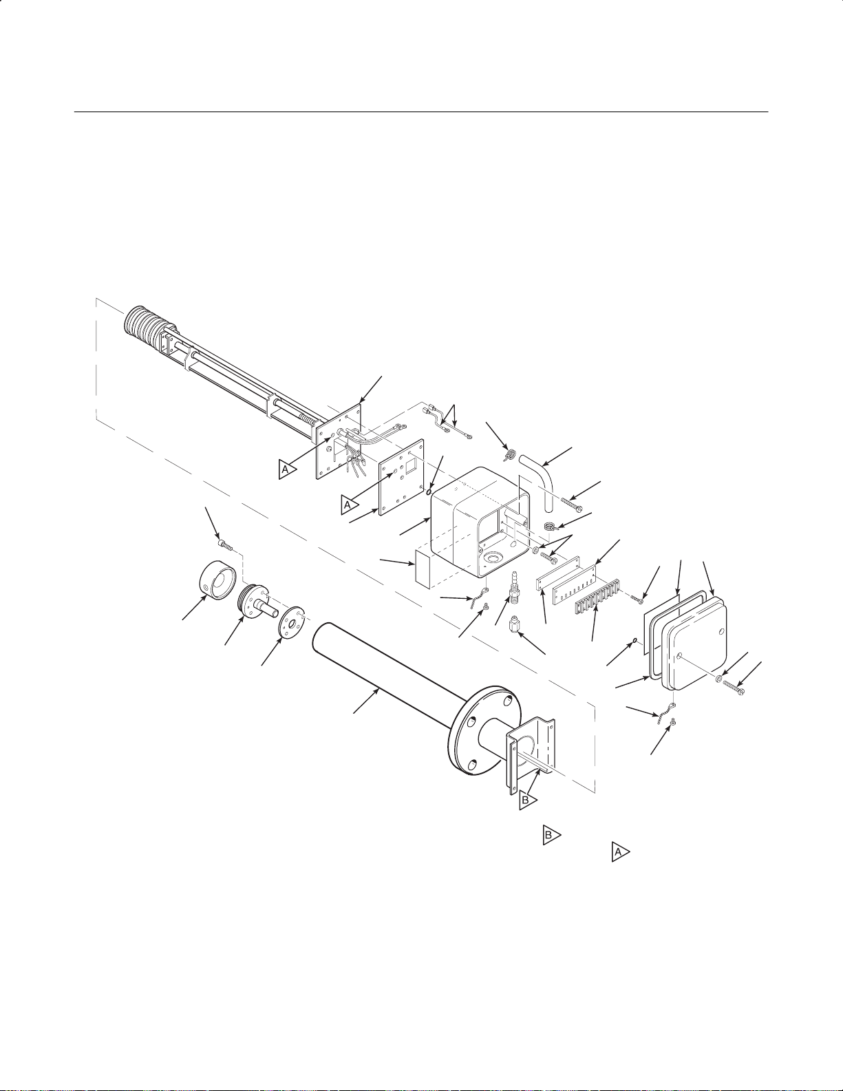
Instruction Manual
Appendix A Rev. 3.6
July 1998
NOTE: NOT ALL PARTS SHOWN ARE AVAILABLE FOR
PURCHASE SEPARATELY. FOR LIST OF
AVAILABLE PARTS, SEE TABLE A-3.
1
APPENDIX A
26
20
World Class 3000
1. Heater, Strut, and Backplate Assembly
2. Diffusion Assembly
3. Retainer Screw
4. Cell and Flange
5. Corrugated Seal
6. Probe Tube Assembly
7. Screw
8. Washer
9. Cover Chain Screw
10. Cover Chain
11. Probe Junction Box Cover
12. Cover Gasket
13. Wiring Diagram
14. O-Ring
15. Terminal Block Screws
16. Terminal Block
17. Terminal Block Marker
18. Terminal Block Mounting Plate
3
2
4
19. Probe Junction Box Screws
20. Hose Clamp
21. Hose
22. Gas Connection
23. Seal Cap
24. Label
25. Probe Junction Box
26. Ground Wires
27. Insulating Gasket
28. Washer
29. Screw
18
23
19
21
16
14
20
12
29
10
17
11
13
15
8
7
9
21240005
28
27
25
24
11
22
10
5
6
NOTE: ITEM , CALIBRATION GAS TUBE,
FITS INTO HOLES WHEN PROBE IS
ASSEMBLED.
Figure A-1. Oxygen Analyzer (Probe) Exploded View
A-0 Appendices Rosemount Analytical Inc. A Division of Emerson Process Management
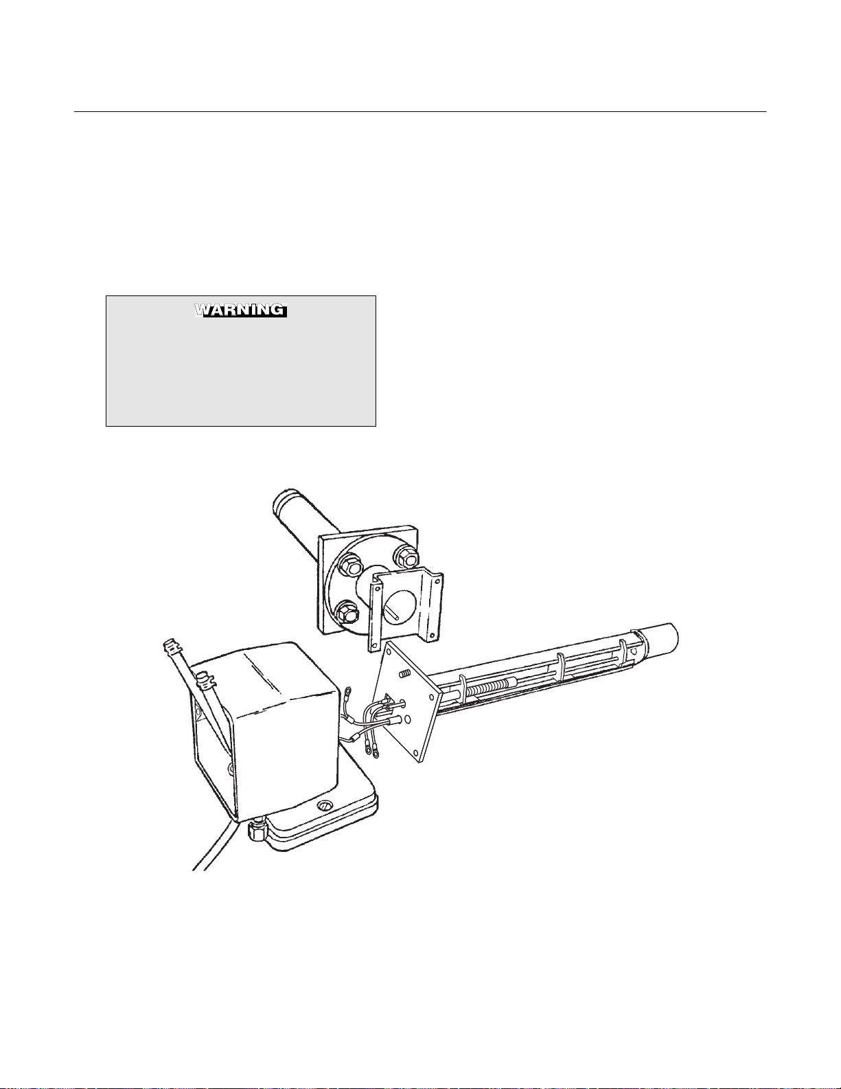
World Class 3000
A
WORLD CLASS 3000 OXYGEN ANALYZER (PROBE)
Instruction Manual
Appendix A Rev. 3.6
July 1998
APPENDIX A, REV. 3.6
DESCRIPTION
A-1 OXYGEN ANALYZER (PROBE) - GENERAL
Read the “Safety instructions for the
wiring and installation of this apparatus” at the front of this Instruction
Bulletin. Failure to follow the safety
instructions could result in serious
injury or death.
PROBE
EXTERIOR
(SENSING CELL INSTALLED)
The Oxygen Analyzer (Probe), Figure A-1, consists of three component groups: probe exterior,
inner probe, and probe junction box, Figure A-2.
PROBE
INTERIOR
PROBE
JUNCTION
BOX
21240006
Figure A-2. Main Probe Components
Rosemount Analytical Inc. A Division of Emerson Process Management Appendices A-1

Instruction Manual
Appendix A Rev. 3.6
July 1998
World Class 3000
Table A-1. Specifications for Oxygen Analyzing Equipment.
1, 2
Probe lengths, nominal .................................................................18 inches (457 mm), 3 feet (0.91 m), 6 feet
(1.83 m), 9 feet (2.74 m), or 12 feet (3.66 m),
depending on duct dimensions
Temperature limits in process
measurement area............................................................ 50° to 1300°F (10° to 704°C)
Standard/current output.................................................................4-20 mA dc signal (factory set)
O
indication (Digital display
2
and analog output)............................................................0.1% O
or ±3% of reading, whichever is
2
greater using Rosemount calibration gases
System speed of response ............................................................less than 3 seconds (amplifier output)
Resolution sensitivity......................................................................0.01% O
transmitted signal
2
HPS 3000 housing.........................................................................NEMA 4X (IP56)
Probe reference air flow.................................................................2 scfh (56.6 L/hr) clean, dry, instrument quality
air (20.95% O
), regulated to 5 psi (34 kPa)
2
Calibration gas mixtures ................................................................Rosemount Hagan Calibration Gas Kit Part No.
6296A27G01 contains 0.4% O
8% O
Nominal
2N2
Nominal and
2N2
Calibration gas flow........................................................................ 5 scfh (141.6 L/hr)
HPS 3000 Power supply.............................................................. 100/110/220 ±10% Vac at 50/60 Hz
HPS 3000 Power requirement.....................................................200 VA
HPS 3000 Ambient Operating Temperature................................32° to 120°F (0° to 50°C)
Ambient operating temperature (Probe Junction Box) .................. 300°F (150°C) max
Approximate shipping weights:
18 inch (457 mm) package ............................................... 55 pounds (24.97 kg)
3 foot (0.91 m) package.................................................... 60 pounds (27.24 kg)
6 foot (1.83 m) package.................................................... 65 pounds (29.51 kg)
9 foot (2.74 m) package.................................................... 72 pounds (32.66 kg)
12 foot (3.66 m) package.................................................. 78 pounds (35.38 kg)
1
All static performance characteristics are with operating variables constant.
2
Equipment ordered utilizing this document as reference will be supplied to the USA standard design. Customers requiring the EEC standard design sho uld req ues t the EEC documentation and utilize its orderi ng data .
Temperatures over 1000°F (537°C) may affect the ease of field cell replaceability.
A-2 Appendices Rosemount Analytical Inc. A Division of Emerson Process Management

World Class 3000
A
Instruction Manual
Appendix A Rev. 3.6
July 1998
A-2 PROBE ASSEMBLY EXTERIOR
Primary probe exterior components include a
flange-mounted zirconium oxide cell, mounted
on a tube assembly and protected by a snubber
diffusion assembly.
a. Cell and Flange Assembly
The primary component in the cell and
flange assembly, Figure A-3, is a
yttria-stabilized zirconium oxide cell. It creates an electrical signal when the oxygen
level on one side is out of balance with the
oxygen level on the other side. This signal
is proportional to the difference in oxygen
levels.
b. Probe Tube Assembly
Four screws secure the cell and flange assembly, Figure A-3, to the probe tube assembly. When in place, the cell is inside the
tube.
The tube assembly includes a flange which
mates with a stack-mounted flange (shown
attached to the probe flange in Figure A-2).
Studs on the stack flange make installation
easy. There is also a tube to carry
calibration gas from the probe junction box
to the process side of the cell during
calibration.
c. Snubber Diffusion Assembly
The snubber diffusion assembly protects
the cell from heavy particles and isolates
the cell from changes in temperature. The
snubber diffusion assembly threads onto
the cell and flange assembly. Pin spanner
wrenches (p robe disassembly kit
3535B42G01) are applied to holes in the
snubber diffusion element hub to remove or
install the snubber diffusion assembly.
An optional ceramic diffusor element and
vee deflector, shown in Figure A-4, is
available. The ceramic diffusor assembly is
also available in a flame arresting version to
keep heat from the cell from igniting flue
gases.
Systems that use an abrasive shield require
a special snubber diffusion assembly with a
hub that is grooved to accept two dust seal
gaskets. This special diffusor is available in
both snubber and ceramic versions. See
Probe Options, section A-6.
DIFFUSION
PROBE TUBE
CORRUGATED
SEAL
CELL AND
FLANGE
ASSEMBLY
21240007
PIN
WRENCH
HUB
ELEMENT
DEFLECTOR
VEE
21240024
Figure A-4. Optional Ceramic Diffusor and Vee
Figure A-3. Cell and Tube Assemblies
Rosemount Analytical Inc. A Division of Emerson Process Management Appendices A-3
Deflector Assembly

Instruction Manual
Appendix A Rev. 3.6
July 1998
World Class 3000
d. Cell - General
The components which make up the cell are
machined to close tolerances and
assembled with care to provide accurate
oxygen measurements. Any replacement
requires attention to detail and care in
assembly to provide good results.
Failure to follow the instructions in
this manual could cause danger to
personnel and equipment. Read and
follow instructions in this manual
carefully.
The oxygen probe includes an inner
electrode for the cell assembly. It consists of
a platinum pad and a platinum/inconel
composite wire which produces the ce ll
constant offset voltage described in the
Nernst equation.
With this pad and wire, the constant will be
between -10 and +15 mV. The cell constant
is noted in the calibration data sheet
supplied with each probe.
b. A heater that is helically wrapped on a
quartz support cylinder and insulated.
c. A chromel-alumel thermocouple which acts
as the sensing element for the temperature
controller. (Not visible in Figure A-5; located
within ceramic support rod.)
d. A platinum screen pad which forms
electrical contact with the inner electrode of
the electrochemical cell. (Not visible in
Figure A-5; located at end of ceram ic
support rod.) The pad is attached to an
inconel wire which carries the signal to the
terminal strip.
e. A V-strut assembly to give support to the
inner probe assembly.
f. A tube to carry reference air to the cell.
Turn to Service and Normal Maintenance, for
repair procedures for probe components.
HEATER
Every probe should be calibrated and
checked after repair or replacement of cell,
pad and wire, heater, and thermocouple, or
after disassembly of the probe.
A-3 INNER PROBE ASSEMBLY
The inner probe assembly, Figure A-5, consists
of six main parts:
a. Ceramic support rod with four holes running
through the length. The holes serve as
insulated paths for the cell signal wire and
thermocouple wires.
INSULATING
V-STRUT
CERAMIC
SUPPORT
ROD
Figure A-5. Inner Probe Assembly
GASKET
REFERENCE
AIR TUBE
27270015
A-4 Appendices Rosemount Analytical Inc. A Division of Emerson Process Management
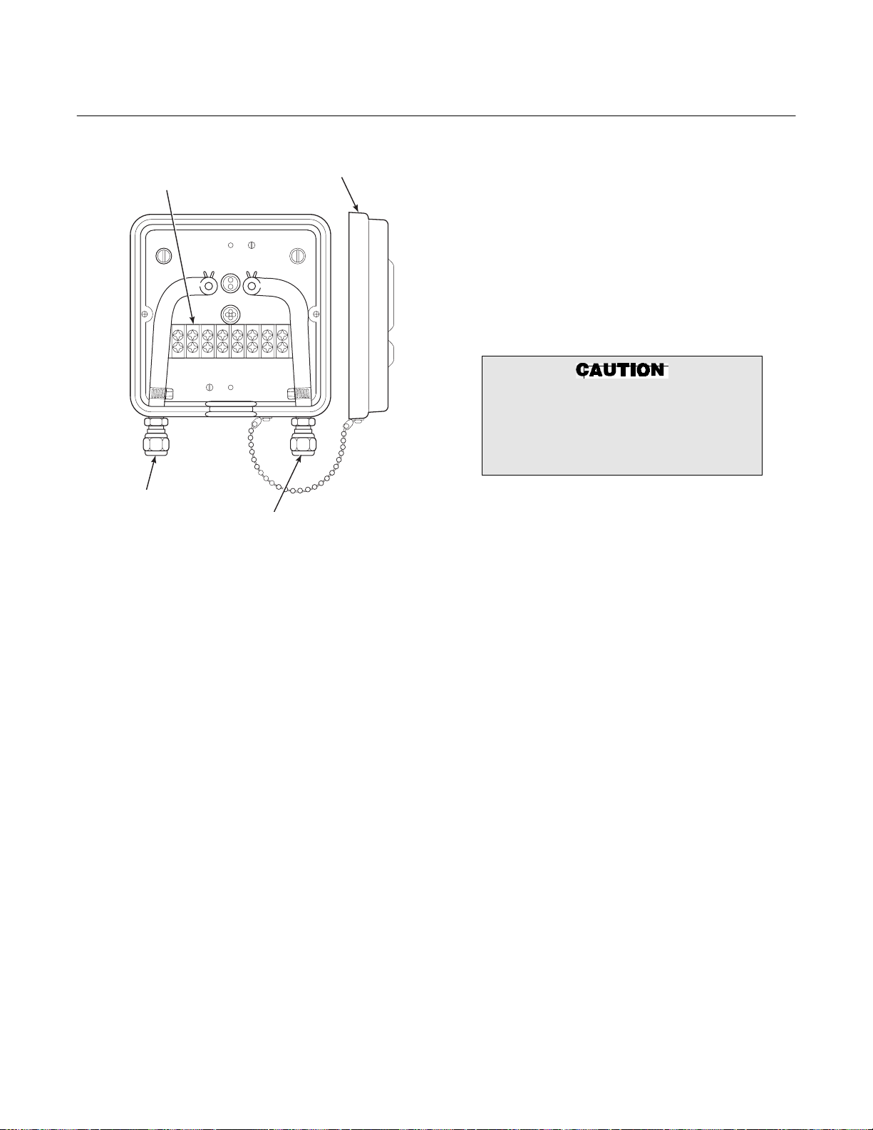
World Class 3000
A
Instruction Manual
Appendix A Rev. 3.6
July 1998
PROBE
JUNCTION BOX
TERMINAL
STRIP
CALIBRATION
GAS FITTING
REFERENCE
AIR FITTING
COVER
Figure A-6. Probe Junction Box
A-4 PROBE JUNCTION BOX
The probe junction box, Figure A-6, is
positioned at the external end of the probe and
contains a terminal strip for electrical
connections and fittings for reference air and
calibration gases. Fittings are for 0.250 inch
stainless steel tubing on American units and
6 mm on European units. The calibration fitting
has a seal cap which must remain in place
except during calibration. A tubing fitting is also
supplied to be used with the calibration gas
supply during calibration.
If the calibration gas bottles will be permanently
hooked up to the probe, a manual block valve is
required at the probe (between the calibration
fitting and the gas line) to prevent condensation
of flue gas down the calibration gas line.
During operation and calibration, reference air is
supplied through the reference air fitting to the
reference side of the cell. This gives the system
a known quantity of oxygen with which to
compare the oxygen level in the process gas.
Though ambient air can be used for this
purpose, accuracy can only be assured if a
reference air set is used.
27270016
During calibration, two gases of different known
oxygen concentrations are injected one at a
time through the calibration gas fitting. Stainless
steel tubing delivers this gas to the process side
of the cell. In a healthy cell, the difference in
oxygen pressure from the process side to the
reference side of the cell will cause a millivolt
output proportional to the difference in oxygen
levels. The electronics unit can use the two
millivolt outputs caused by the two calibration
gases for either automatic or semi-automatic
calibration.
Do not attempt to remove a process
gas sample through either gas fitting.
Hot gases from the process would
damage gas hoses in the probe
junction box.
A-5 CABLE ASSEMBLY
The system uses a 7-conductor cable to
connect the probe to the electronics package.
Standard length for this cable is 20 feet (6 m),
but lengths up to 150 feet (45 m) are available.
The seven conductors include one shielded pair
of wires for the cell millivolt signal, one shielded
pair of type K wires for the thermocouple, and
three individual 16-gauge wires for the heater
and for ground. The assembled conductors are
wrapped by a type K Teflon
TM
jacket and
braided stainless steel shield. The Teflon
stainless steel jacketing is suitable for high
temperature use. All metal shields are isolated
at the probe end and connect by drain wires to
ground at the electronics.
A-6 PROBE OPTIONS
a. Abrasive Shield Assembly
The abrasive shield assembly, Figure A-7,
is a stainless-steel tube that surrounds the
probe assembly. The shield protects the
probe against particle abras ion and
corrosive condensations, provides a guide
for ease of insertion, and acts as a probe
position support, especially for longer length
probes. The abrasive shield assembly uses
a modified diffusor and vee deflector
assembly, fitted with dual dust seal packing.
TM
and
Rosemount Analytical Inc. A Division of Emerson Process Management Appendices A-5

Instruction Manual
Appendix A Rev. 3.6
July 1998
World Class 3000
2
.187
.187
1
B
A
o
15
3.584
3.554
A
.45 MIN
VIEW A
o
90
ON INSIDE BREAK
FOR SMOOTH
ROUNDED EDGE ON
BOTH ENDS
OF CHAMFER
125
.187
6.00
SKIN CUT FACE FOR 90
o
B
VIEW B
o
22.5
0.75 THRU 4 PLS,
EQ SP ON 4.75 B.C.
NOTES:
16860033
1 WELD ON BOTH SIDES WITH EXPANDING
CHILL BLOCK.
2 BEFORE WELDING, BUTT ITEM 2 OR 4 WITH
ITEM 1 AS SHOWN.
.745
DIA ON A 7.50 DIA B.C. (REF)
.755
Figure A-7. Abrasive Shield Assembly
NOTE
In highly abrasive applications, rotate the shield 90 degrees at normal
service intervals to present a new wear surface to the abrasive flow stream.
A-6 Appendices Rosemount Analytical Inc. A Division of Emerson Process Management

World Class 3000
A
Instruction Manual
Appendix A Rev. 3.6
July 1998
P0010
Figure A-8. Ceramic Diffusion/Dust Seal Assembly
These modified diffusion and vee deflector
assemblies are available in standard, Figure
A-8, and flame arrestor version, Figure A-9.
b. Ceramic Diffusion Assembly
The ceramic diffusion assembly, Figure
A-10, is the traditional design for the probe.
Used for over 25 years, the ceramic diffusion assembly provides a greater filter surface area for the probe.
19280010
Figure A-10. Ceramic Diffusion Assembly
c. Flame Arrestor Diffusion Assembly
Where a high concentration of unburned
fuel is present in the exhaust gases, a flame
arrestor diffusion assembly, Figure A-9 and
Figure A-11 is recommended.
The flame diffusion assembly includes a set
of baffles between the cell and the stack
gases. This keeps 1500°F (816°C) cell temperatures from igniting unburned fuel in the
stack.
P0012
Figur e A-9 . Flam e Arrestor Diffusion/D ust
P0011
Figure A-11. Flame Arrestor Diffusion Assembly
Seal Assembly
Rosemount Analytical Inc. A Division of Emerson Process Management Appendices A-7
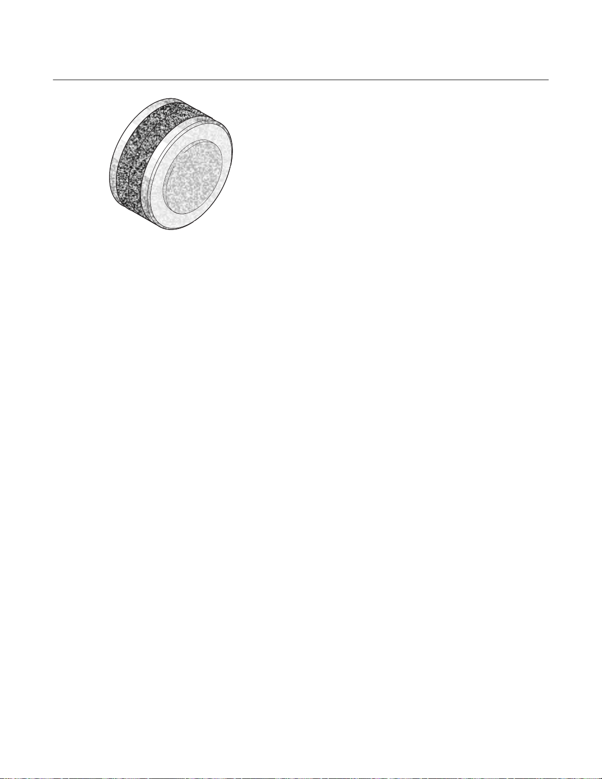
Instruction Manual
Appendix A Rev. 3.6
July 1998
World Class 3000
an 18 inch (457 mm) or 3 foot (0.92 m)
probe mounted externally on the stack or
duct. The process or exhaust gases are directed out to the probe through a passive
sampling system using inconel tubes. Flue
gas flow induces the movement of gases
into, through, and out of the bypass unit.
The bypass arrangement does not require
the use of aspiration air and the gas which
flows past the probe is returned to the stack
or duct.
Figure A-12. Snubber Diffusion/Dust
Seal Assembly
d. Snubber Diffusion/Dust Seal Assembly
The snubber diffusion/dust seal assembly,
Figure A-12, is used in applicat io ns where
an abrasive shield is to be used with a
snubber type diffusion element. The dust
seal consists of two rings of packing to prevent abrasive dust from collecting inside the
abrasive shield.
e. Bypass Probe Options
For processes where the flue gas exceeds
the maximum allowable temperature of
1300°F (704°C) a bypass sensor package
can be employed. The bypass system uses
The bypass probe package is normally used
for process temperatures of 1300°F (704°C)
to 2000°F (1094°C). A higher temperature
version of the bypass provides for operation
at temperatures up to 2500°F (1372°C). In
this version the pick up tubes are made of a
special high-temperature alloy.
Overall dimensions and mounting details of
the American and European bypass systems are shown in Figure A-13.
f. Probe Mounting Jacket Options
A probe mounting jacket option is available
to allow the probe to operate at temperatures of up to 2000°F (1095°C). A separate
instruction bulletin is available for this
option.
A-8 Appendices Rosemount Analytical Inc. A Division of Emerson Process Management

World Class 3000
A
A-A
Instruction Manual
Appendix A Rev. 3.6
July 1998
OF FLOW
DIRECTION
27270017
REFERENCE AIR SUPPLY CONNECTION BITE TYPE FITTING (PARKER CPI) FOR
0.250 O.D. TUBING. 2 SCFH AT 3 PSIG MAX. CLEAN DRY AIR REQUIRED. FITTING
IS LOCATED ON FAR SIDE.
1.
NOTES:
CALIBRATION AND PURGE GAS CONNECTION. BITE TYPE FITTING (PARKER CPI)
10 SCFH AT 32 PSIG MAX. CALIBRATION GAS REQUIRED.
LAG TO ENSURE GAS TEMPERATURE DOES NOT GO BELOW DEW POINT OR
2.
3.
o
EXCEED 500 C.
A
oooo
FLUE GAS OPERATING TEMPERATURE RANGE 1200 TO 1800 F (650 TO 980 C).
INSTALL WITH ANALYZER IN A VERTICALLY DOWNWARDS DIRECTION ONLY.
4.
5.
RECOMMENDED TWO INCH THK INSULATION. THERMAL CONDUCTIVITY K
EQUALS 0.5 FOR INSULATION.
DIMENSIONS ARE IN INCHES WITH MILLIMETERS IN PARENTHESES.
6.
7.
01
GROUP NOTE
A 3 FT (914.4) GAS TUBE PICK-UP
FLANGE
B6FT(1828.8) GAS TUBE PICK-UP
C9FT(2743.2) GAS TUBE PICK-UP
GASKET AND HARDWARE
06
CAL
GAS
2
ELECT CABLE
BY CUSTOMER
OPTIONAL MOUNTING
ARRANGEMENT, 4 IN.
150# FLANGE SUPPLIED
05
HARDWARE
GASKET AND
06
REF
1
AIR
4.026
VIEW
04
02 03
I.D.
(102.26)
30.62 (777.75) REF (4507C26G01)
62.50 (1587.5) REF (4507C26G03)
26.50 (673.1) REF (4507C26G01 AND G02)
6.0
(152.4) REF
6.50
(165.1) REF
37.00 (939.8) REF (4507C26G01)
73.00 (1854.2) REF (4507C26G02)
109.00 (2768.6) REF (4507C26G03)
DRAIN
STD 20 FT
(6.1 M) CABLE
A
4
6
3
FOR
FOR PROBE
27.31 (693.67)
CLEARANCE REQ
INSERTION
AND REMOVAL
3D3947G01
19.80 (502.92)
IF EQUIPPED WITH THE OPTIONAL
CERAMIC DIFFUSOR ASSEMBLY, PROBE
VEE SHIELD IS SQUARE TO GAS FLOW.
ASSEMBLY MUST BE ORIENTED SO THAT
Figure A-13. Bypass Probe Option (Sheet 1 of 3)
Rosemount Analytical Inc. A Division of Emerson Process Management Appendices A-9

Instruction Manual
Appendix A Rev. 3.6
July 1998
World Class 3000
Y CONNECTION BITE TYPE FITTING (PARKER CPI) FOR
A-A
o
VIEW
o
o
o
GROUP NOTE
o
o
A 3 FT (914.4) GAS TUBE PICK-UP
B6FT(1828.8) GAS TUBE PICK-UP
C9FT(2743.2) GAS TUBE PICK-UP
CAL
GAS
2
ELECT
CABLE
16
15
14
REF
1
13
12
11
AIR
04
03
02
OF FLOW
DIRECTION
I.D.
4.026
(102.26)
PICKUP (3D390004G07 OR G08)
26.5 (673.1) ON 3 FT (914.4) OR 6 FT (1828.8)
62.5 (1587.5) ON 9 FT (2743.2) PICKUP (3D390004G09)
27270018
37.0 (939.8) ON 3 FT (914.4) PICKUP (3D390004G07)
73.0 (1854.2) ON 6 FT (1828.8) PICKUP (3D390004G08)
109.0 (2768.6) ON 9 FT (2743.2) PICKUP (3D390004G09)
0.250 O.D. TUBING. 2 SCFH AT 3 PSIG (20.69 kPa GAUGE) MAX. CLEAN DRY AIR
REQUIRED. FITTING IS LOCATED ON FAR SIDE.
1.
NOTES: REFERENCE AIR SUPPL
STD CABLE
20 FT (6.1 M)
CALIBRATION AND PURGE GAS CONNECTION. BITE TYPE FITTING (PARKER CPI)
10 SCFH AT 32 PSIG (220.64 kPa GAUGE) MAX. CALIBRATION GAS REQUIRED.
EXCEED 932 F (500 C).
LAG TO ENSURE GAS TEMPERATURE DOES NOT GO BELOW DEW POINT OR
3.
2.
A
A
RECOMMENDED 2.0 INCH (50.8) THK INSULATION. THERMAL CONDUCTIVITY K EQUAL
0.5 FOR INSULATION.
FLUE GAS OPERATING TEMPERATURE RANGE 1200 TO 1800 F (650 TO 980 C).
5.
01
6.
27.31 (693.67)
DIMENSIONS ARE IN INCHES WITH MILLIMETERS IN PARENTHESES.
7.
FLANGE
INSERTION
FOR PROBE
AND REMOVAL
CLEARANCE REQ
08
06 07
AND
GASKET
HARDWARE
4
WELD BY CUSTOMER
10
09
05
19.80
FOR
(502.92)
3D3947G01
PLATE
WELDED
TO STACK
6.50 (165.1) REF
DRAIN
3
6
IF EQUIPPED WITH THE OPTIONAL
CERAMIC DIFFUSOR ASSEMBLY, PROBE
VEE SHIELD IS SQUARE TO GAS FLOW.
ASSEMBLY MUST BE ORIENTED SO THAT
INSTALL WITH ANALYZER IN A VERTICALLY DOWNWARDS DIRECTION ONLY.
4.
Figure A-13. Bypass Probe Option (Sheet 2 of 3)
A-10 Appendices Rosemount Analytical Inc. A Division of Emerson Process Management

World Class 3000
A
Instruction Manual
Appendix A Rev. 3.6
July 1998
Extended Temperature By-Pass Arrangements (2400°°°°F; 1300°°°°C)
GROUP
PART NO.
1U0571 G01 3’ By-pass Package with ANSI bolt pattern.
1U0571 G02 6’ By-pass Package with ANSI bolt pattern.
1U0571 G03 9’ By-pass Package with ANSI bolt pattern.
1U0571 G04 3’ By-pass Package with JIS bolt pattern.
1U0571 G05 6’ By-pass Package with JIS bolt pattern.
1U0571 G06 9’ By-pass Package with JIS bolt pattern.
1U0571 G07 3’ By-pass Package with DIN bolt pattern.
1U0571 G08 6’ By-pass Package with DIN bolt pattern.
1U0571 G09 9’ By-pass Package with DIN bolt pattern.
Figure A-13. Bypass Probe Option (Sheet 3 of 3)
Rosemount Analytical Inc. A Division of Emerson Process Management Appendices A-11
CODE DESCRIPTION

Instruction Manual
Appendix A Rev. 3.6
July 1998
World Class 3000
PROBE TROUBLESHOOTING
A-7 OVERVIEW
The probe troubleshooting section describes
how to identify and isolate faults which may develop in the probe assembly.
Install all protective equipment and
safety ground leads after troubleshooting. Failure to replace covers
and ground leads could result in serious injury or death.
A-8 PROBE TROUBLESHOOTING
a. Probe Faults
Listed below are the four symptoms of
probe failure.
Symptom Check Fault Remedy
1. No response to oxygen concentration
change when:
1. The system does not respond to
changes in the oxygen concentrat ion.
2. The system responds to oxygen
changes but does not give the correct
indication.
3. The system does not give an acceptable indication of the value of the oxygen calibration gas being applied
during calibration.
4. The system takes a long time to return
to the flue gas value after the calibration gas is turned off.
b. Table A-2 provides a guide to fault finding
for the above symptoms.
c. Figure A-14 and Figure A-15 provide an al-
ternate approach to finding probe related
problems.
Table A-2 . Fault Finding
Heater is cold and TC
mV output is less than
set point
Heater is hot and T/C
mV output is at set
point ±0.2 mV
A-12 Appendices Rosemount Analytical Inc. A Division of Emerson Process Management
Thermocouple continuity Thermocouple failure Replace thermocouple
or return probe to
Rosemount.
Heater cold resistance to
be 11 ohm to 14 ohm
Triac O/P to heater Failure of electronics Check HPS and electron-
Recorder chart Recorder failure See Recorder Instruction
Cell mV input to electronics and cell mV at probe
junction box
Heater failure Replace heater or return
probe to Rosemount.
ics package.
Manual.
No cell mV at probe when
calibration gas applied
Probe cell mV OK but no
input to electronics
Cell mV satisfactory both
at probe junction box and
input to electronics - failure of electronics
Replace cell or return
probe to Rosemount.
Check out cable
connection.
Check electronics
package.

World Class 3000
A
Symptom Check Fault Remedy
2. System responds to
oxygen concentration
changes but does not
give correct indication
Instruction Manual
Appendix A Rev. 3.6
July 1998
Table A-2. Fault Finding (Continued)
Good response, with
incorrect indication
3. System does not give
accurate indication of
applied calibration gas
4. System takes a long
time to return to flue
gas value after calibration gas is turned off
Recorder or remote
indicator
System calibration Calibration error Recalibrate system.
Probe mounting and con-
dition of duct
Cell mV input to
electronics
Calibration gas input port Blocked port Clean port. If the flue gas
Ceramic diffusion element Diffusion element cracked,
Diffusion element Plugged diffusion element Change diffusion element
Calibration error Recalibrate recorder or
indicator. Reference Recorder Instruction Manual.
Air ingress into duct Stop air leaks or resite
probe.
Failure of electronics Check electronics
package.
is condensing in the calibration gas line, insulate
the back of the probe.
Make sure that the calibration gas line is capped
between calibrations, or a
check valve is installed.
Replace diffusion element.
broken, or missing
or snubber diffusion
element.
Rosemount Analytical Inc. A Division of Emerson Process Management Appendices A-13

Instruction Manual
Appendix A Rev. 3.6
July 1998
World Class 3000
Figure A-14. Flowchart of Probe Related Problems, #1
A-14 Appendices Rosemount Analytical Inc. A Division of Emerson Process Management
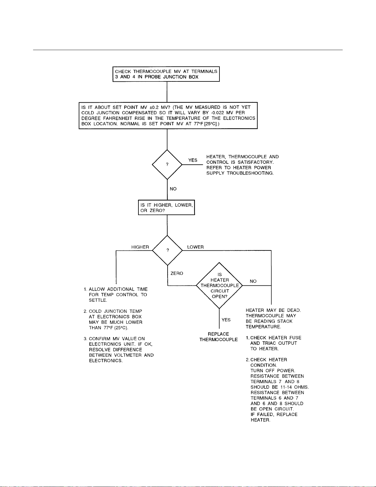
World Class 3000
A
Instruction Manual
Appendix A Rev. 3.6
July 1998
Figure A-15. Flowchart of Probe Related Problems, #2
Rosemount Analytical Inc. A Division of Emerson Process Management Appendices A-15

Instruction Manual
Appendix A Rev. 3.6
July 1998
World Class 3000
SERVICE AND NORMAL MAINTENANCE
NOTE
!
UPON COMPLETING INSTALLATION, MAKE SURE THAT THE PROBE IS TURNED ON AND OPERATING
PRIOR TO FIRING UP THE COMBUSTION PROCESS. DAMAGE CAN RESULT FROM HAVING A COLD
PROBE EXPOSED TO THE PROCESS GASES.
During outages, and if possible, leave all probes running to prevent condensation and premature aging from thermal cycling.
If the ducts will be washed down during outage, MAKE SURE to power down the probes and
remove them from the wash area.
A-9 OVERVIEW
This section describes routine maintenance of
the oxygen analyzer probe. Spare parts referred
to are available from Rosemount. Probe disassembly kit 3535B42G01 contains the required
spanner and hex wrenches. Refer to the following section of this appendix for part numbers
and ordering information.
Install all protective equipment covers
and safety ground leads after equipment repair or service. Failure to install covers and ground leads could
result in serious injury or death.
A-10 PROBE RECALIBRATION
The oxygen analyzer system should be calibrated when commissioned. Under normal circumstances the probe will not require frequent
calibration. When calibration is required, follow
the procedure described in the Instruction Bulletin applicable to your electronics package.
A-11 CELL REPLACEMENT
precise surface finishes. Do not remove items
from packaging until they are ready to be used.
Spanner wrenches and hex wrenches needed for
this procedure are part of an available special
tools kit, Table A-3.
Wear heat resistant gloves and clothing to remove probe from stack. Normal operating temperatures of diffusor
and vee deflector are approximately
600° to 800°F (316° to 427°C). They
could cause severe burns.
Disconnect and lock out power before
working on any electrical components.
There is voltage up to 115 Vac.
Do not remove cell unless it is certain
that replacement is needed. Removal
may damage cell and platinum pad. Go
through complete troubleshooting
procedure to make sure cell needs replacement before removing it.
This paragraph covers oxygen sensing cell replacement. Do not attempt to replace the cell
until all other possibilities for poor performance
have been considered. If cell replacement is
needed, order cell replacement kit, Table A-3.
The cell replacement kit contains a cell and
flange assembly, corrugated seal, setscrews,
socket head cap screw s, an d anti-seize compound. Items are carefully packaged to preserve
A-16 Appendices Rosemount Analytical Inc. A Division of Emerson Process Management
a. Disconnect and lock out power to electron-
ics. Shut off and disconnect reference air
and calibration gas supplies from probe
junction box, Figure A-16. Wearing heat resistant gloves and clothing, remove probe
assembly from stack carefully and allow to
cool to room temperature. Do not attempt to
work on unit until it has cooled to a comfortable working temperature.
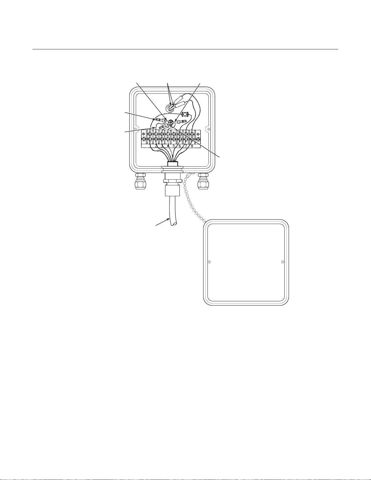
World Class 3000
A
Instruction Manual
Appendix A Rev. 3.6
July 1998
BOMB TAIL
CONNECTOR
CELL EXTENSION
WIRE (ORANGE)
INCONEL
CELL WIRE
(CLEAR
SLEEVING)
CALIBRATION
GAS FITTING
CABLE
HEATER
WIRES
(BLACK
SLEEVING)
THERMOCOUPLE -
(RED ALUMEL)
THERMOCOUPLE +
(YELLOW CHROMEL)
REFERENCE
AIR FITTING
Figure A-16. Cell Wiring Connection
b. If the probe uses the standard diffusion
element, use a spanner wrench to remove
the diffusion element.
c. If equipped with the optional ceramic diffusor
assembly, remove and discard setscrews,
Figure A-17, and remove vee deflector. Use
spanner wrenches from probe disassembly
kit, Table A-3, to turn hub free from retainer.
Inspect diffusion element. If damaged, replace element.
d. Loosen four socket head cap screws from
the cell and flange assembly and remove
the assembly and the corrugated seal. The
cell flange has a notc h wh ic h m a y be used
PROBE JUNCTION
BOX COVER
27270019
to gently pry the flange away from the
probe. Note that the contact pad inside the
probe will sometimes fuse to the oxygen
sensing cell. If the cell is fused to the contact pad, push the cell assembly back into
the probe (against spring pressure), and
quickly twist the cell assembly. The cell and
contact pad should separate. If the contact
pad stays fused to the cell, a new contact/thermocouple assembly must be installed. Disconnect the cell and the
thermocouple wires at the probe juncti on
box, and withdraw the cell with the wires still
attached (see paragraph A-13).
Rosemount Analytical Inc. A Division of Emerson Process Management Appendices A-17

Instruction Manual
Appendix A Rev. 3.6
July 1998
World Class 3000
PIN
WRENCH
OPTIONAL CERAMIC
DIFFUSION ELEMENT
FILLET
SETSCREW
VEE
DEFLECTOR
CEMENT
PORT
RETAINER
HUB
CEMENT
Figure A-17. Removal of Optional D if fu sor
and Vee Deflector
PROBE TUBE
(NOT INCLUDED
IN KIT)
CORRUGATED
SEAL
CELL AND
FLANGE
ASSEMBLY
SOCKET HEAD
CAP SCREWS
CALIBRATION GAS
PASSAGE
21240026
g. Rub a small amount of anti-seize on both
sides of new corrugated seal.
h. Assemble cell and flange assembly, corru-
gated seal, and probe tube. Make sure the
calibration tube lines up with the calibration
gas passage in each component. Apply a
small amount of anti-seize compound to
screw threads and use screws to secure
assembly. Torque to 55 in-lbs (4 N
•
m).
i. Apply anti-seize compound to threads of
cell assembly, hub, and setscrews. Reinstall
hub on cell assembly. Using pin spanner
wrenches, torque to 10 ft-lbs (14 N
•
m). If
applicable, reinstal l vee def lec tor , or ie nti ng
apex toward gas flow. Secure with
setscrews and anti-seize compound.
Torque to 25 in-lbs (2.8 N
•
m).
j. On systems equipped with an abrasive
shield, install dust seal gaskets, with joints
o
180
apart.
k. Reinstall probe and gasket on stack flange.
If there is an abrasive shield in the stack,
make sure dust seal gaskets are in place as
they enter 15
o
reducing cone.
l. Turn power on to electronics and monitor
thermocouple outpu t . It sh o uld stab iliz e at
29.3 ±0.2 mV. Set reference air flow at 2 scfh
(56.6 L/hr). After probe stabilizes, calibrate
probe per Instruction Bulletin applicable to
your electronics package. If new components
have been instal le d, rep ea t cal ib rat io n a fte r
24 hours of operation.
21240009
Figure A-18. Cell Replacement Kit
e. If contact assembly is damaged, replace
A-12 OPTIONAL CERAMIC DIFFUSION
ELEMENT REPLACEMENT
a. General
contact and thermocouple according to
paragraph A-13, Replacem ent of Contac t
and Thermocouple Assembly.
The diffusion element protects the cell from
particles in process gases. It does not normally need to be replaced because the vee
f. Remove and discard corrugated seal. Clean
mating faces of probe tube and retainer.
Remove burrs and raised surfaces with
block of wood and crocus cloth. Clean
threads on retainer and hub.
deflector protects it from particulate erosion.
In severe environments the filter may be
broken or subject to excessive erosion. Examine the diffusion element whenever removing the probe for any purpose. Replace
if damaged.
A-18 Appendices Rosemount Analytical Inc. A Division of Emerson Process Management

World Class 3000
A
Instruction Manual
Appendix A Rev. 3.6
July 1998
Damage to the diffusion element may become apparent during calibration. Compare
probe response with previous response. A
broken diffusion element will cause a slower
response to calibration gas.
Hex wrenches needed to remove setscrews
and socket head screws in the following procedure are available as part of a special tool
kit, Table A-3.
Wear heat resistant gloves and clothing to remove probe from stack. Normal operating temperatures of diffusor
and vee deflector are approximately
600° to 800°F (300° to 425°C). They can
cause severe burns.
Disconnect and lock out power before
working on any electrical component.
There is voltage up to 115 Vac.
3. On systems equipped with abrasive
shield, remove dual dust seal gaskets.
4. Use spanner wrenches from special
tools kit, Table A-3, to turn hub free
from retainer.
5. Put hub in vise. Br eak out old diffusion
element with chisel along cement line
and 3/8 inch (9.5 mm) pin punch
through cement port.
6. Break out remaining diffusion element
by tapping lightly around hub with
hammer. Clean grooves with pointed
tool if necessary.
7. Replace diffusion element, using replacement kit listed in Table A-3. This
consists of a diffusion element, cement, setscrews, anti-seize compound
and instructions.
8. Test fit replacement element to be sure
seat is clean.
It is not necessary to remove the cell
unless it is certain that replacement is
necessary. Cell cannot be removed for
inspection without damaging it. Refer
to paragraph A-11, Cell Replacement.
b. Replacement Procedure
1. Shut off power to electronics. Disconnect cable conductors and remove cable, Figure A-16. Shut off and
disconnect reference air and calibration
gas supplies from probe junction box.
Wearing heat resistant gloves and
clothing, carefully remove probe assembly from stack and allow to cool to
room temperature. Do not attempt to
work on unit until it has cooled to a
comfortable working tem peratur e.
2. Loosen setscrews, Figure A-17, using
hex wrench from special tools kit,
Table A-3, and remove vee deflector.
Inspect setscrews. If damaged, replace
with M-6 x 6 stainless setscrews
coated with anti-seize compound.
Do not get cement on diffusion element except where it touches the hub.
Any cement on ceramic element
blocks airflow through element. Wiping wet cement off of ceramic only
forces cement into pores.
9. Thoroughly mix cement and insert tip
of squeeze bottle into cement port. Tilt
bottle and squeeze while simultaneously turning diffusion element into
seat. Do not get any cement on upper
part of diffusion element. Ensure complete penetration of cement around
three grooves in hub. Cement should
extrude from opposite hole. Wipe excess material back into holes and wipe
top fillet of cement to form a uniform
fillet. (A Q-Tip is useful for this.) Clean
any excess cement from hub with
water.
10. Allow filter to dry at room temperature
overnight or 1 to 2 hours at 200°F
(93°C).
Rosemount Analytical Inc. A Division of Emerson Process Management Appendices A-19
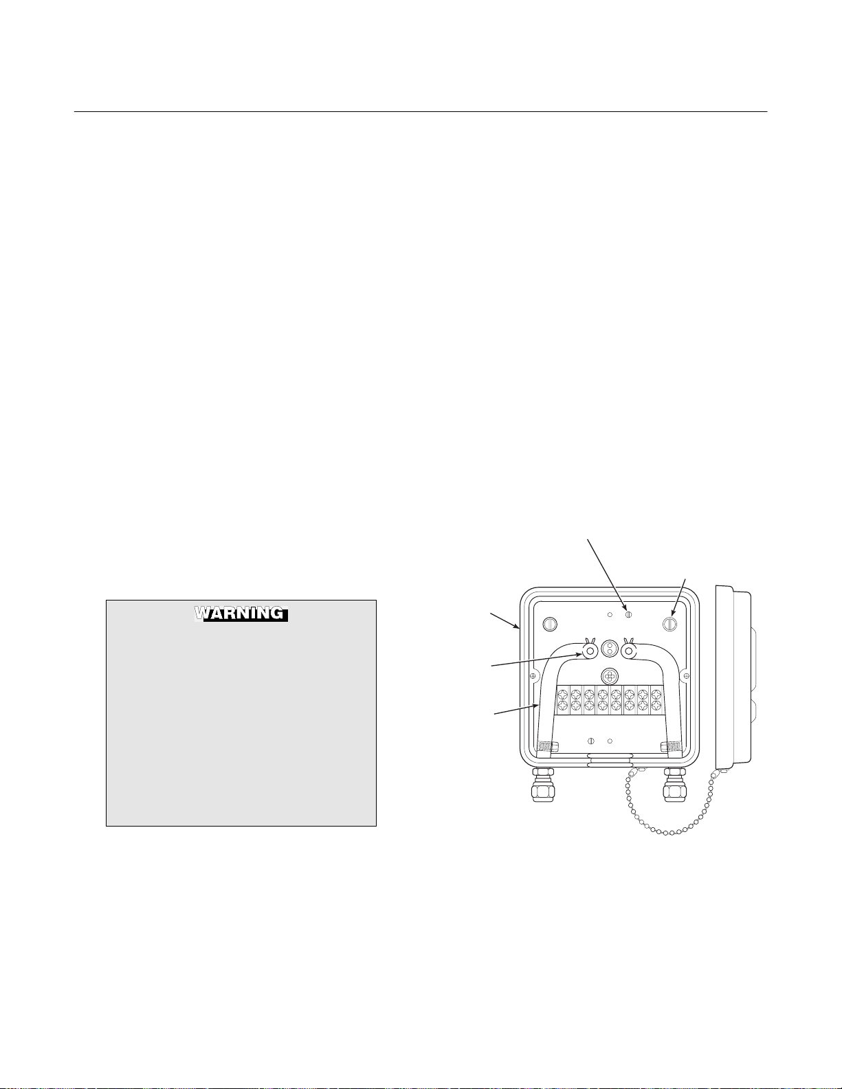
Instruction Manual
Appendix A Rev. 3.6
July 1998
World Class 3000
11. Wipe a heavy layer of anti-seize compound onto the threads and mating
surfaces of the diffusion hub and
retainer.
12. Assemble retainer and diffusion hub
with two pin spanner wrenches. Torque
to 10 ft-lbs (14 N·m).
13. On systems equipped with abrasive
shield, install dust seal gaskets with
joints 180° apart.
14. Reinst al l vee deflec tor , orienting apex
toward gas flow. Apply anti-seize compound to setscrews and tighten with
hex wrench.
15. Reinstall probe on stack flange.
16. Turn power on to electronics and
monitor thermocouple output. It should
stabilize at 29.3 ±0.2 mV. Calibrate
probe per Instruction Bulletin applicable to your electronics pack age.
A-13 REPLACEMENT OF CONTACT AND
THERMOCOUPLE ASSEMBLY
Use heat resistant gloves and clothing when removing probe junction box
and inner probe assembly. Do not attempt to work on these components
until they have cooled to room temperature. Probe components can be as
hot as 800°F (427°C). This can cause
severe burns.
Squeezing tabs on hose clamps, remove
hoses from probe junction box, Figure A-19.
Remove four screws in corners of probe
junction box. Pull probe junction box and inner probe assembly free from probe tube.
Set on bench and allow to cool to room
temperature.
b. Disconnect cell extension wire (orange),
thermocouple wire (red alumel), and thermocouple wire (yellow chromel) by cutting
bomb tail connections from the terminal
strip, Figure A-16.
c. Remove two screws, Figure A-19, lock-
washers, and flat washers that connect
probe junction box to inner probe assembly.
Pull heater, V-st rut and ba ckpl a te assembly
away from probe junction box. Inspect all
O-rings and insul at in g gaske t; r epl ac e i f wor n
or damaged.
PROBE JUNCTION BOX TO HEATER,
STRUT, AND BACKPLATE
ASSEMBLY SCREW
PROBE JUNCTION BOX
INNER PROBE ASSEMBLY
TO PROBE TUBE SCREWS
PROBE
JUNCTION
BOX
HOSE
CLAMP
HOSE
Disconnect and lock out power before
working on any electrical components.
There is voltage up to 115 Vac.
21240027
a. Disconnect and lock out power to electron-
ics. Using heat resistant gloves and cloth-
Figure A-19. Probe Junction Box Mechanical
Connections
ing, remove probe junction box cover.
A-20 Appendices Rosemount Analytical Inc. A Division of Emerson Process Management

World Class 3000
A
Instruction Manual
Appendix A Rev. 3.6
July 1998
d. Use a pencil to mark locations of spring clip
on ceramic rod, Figure A-20.
e. Pry or squeeze tabs on sp ring cli ps, an d pull
contact and thermocouple assembly out of
probe assembly. Retain spring clips and
spring; replace if damaged.
Be very careful when handling contact
and thermocouple assembly. The ceramic rod in this assembly is fragile.
f. While very carefully handling new contact
and thermocouple assembly, lay old assembly next to new one. Transfer pencil
marks to new rod.
HEATER SCREWS
(NOT SHOWN)
V-STRUT
MOUNTING SCREW
(REAR VIEW)
CONTACT AND
THERMOCOUPLER
ASSEMBLY
g. Note wire lengths of old assembly as an aid
for trimming new lengths in step (j). Trimming of wires will not always be necessary.
Throw away old contact and thermocouple
assembly.
h. Carefully guide new contact and thermo-
couple assembly through V-strut assembly
leaf spring (4, Figure A-21), spring (9),
spring clip (10) (held open by squeezing
tabs), and tube supports (11, 13) until
spring clip reaches pencil mark.
i. Reinstall insulating gasket on backplate, re-
place two screws, O-rings, lockwashers and
flat washers connecting probe junction box
to inner probe assembly.
Do not trim new wiring shorter than
existing (old) wiring. Excessive wire
trim will prevent connections from
being properly made and will require a
new replacement kit.
INSULATING
GASKET
SPRING
CLIP
Figure A-20. Inner Probe Replacement
(Heater, V-Strut, and Backplate Assembly)
1
13
12
1. Heater Ceramic Rod
2. Contact and Thermocouple Assembly
3. Strut
4. Leaf Spring
3
2
11
HEATER
CERAMIC ROD
21240010
5. Ring Lug
6. Butt Connector
7. Extension
8. Backplate
j. Trim wires, if necessary, as noted in
step (g).
k. Connect color coded wires to proper termi-
nals as shown in Figure A-16. Rosemount
recommends connecting the thermocouple
wires directly to the terminal strip. This is
because the junction of different metals at
the wires and lugs and at the lugs and the
4
5
6
1011
9
8
7
9. Spring
10. Spring Clip Assembly
11. Common Tube Support
12. Heater
13. Short Tube Support
4
8
Figure A-21. Heater, St rut, and Backplate Assembly
(Inner Probe Assembly)
Rosemount Analytical Inc. A Division of Emerson Process Management Appendices A-21

Instruction Manual
Appendix A Rev. 3.6
July 1998
World Class 3000
terminal strip could act as additional thermocouple junctions. This could produce a
voltage that would affect the thermocouple
output si gnal.
Do not bend wires closer than 1/4 inch
(6.4 mm) from end of ceramic rod. Dress
wires so they do not touch sides of probe
junction box.
l. Slide assembled probe junction box and in-
ner probe assembly into probe tube. To
align calibration gas tube with corresponding hole in backplate (A, B, Figure A-1), insert scriber through hole in backplate and
into calibration gas tube. Secure with
screws. Reinstall hoses and probe junction
box cover.
m. Power up system. Monitor thermocouple
output. It should stabilize at set point mV
±0.2 mV. Recalibrate probe per Instruction
Bulletin applicable to your elec tron ic s
package.
A-14 REPLACEMENT OF HEATER, V-STRUT
AND BACKPLATE ASSEMBLY (INNER
PROBE ASSEMBLY; INCLUDES CONTACT
AND THERMOCOUPLE ASSEMBLY)
Use heat resistant gloves and clothing
when removing probe junction box
and inner probe assembly. Do not attempt to work on these components
until they have cooled to room temperature. Probe components can be as
hot as 800° (427°C). This can cause
severe burns.
a. Disconnect and lock out power to electron-
ics. Using heat resistant gloves and clothing, remove probe cover. Squeezing tabs
on hose clamps and remove hoses from
probe junction box, Figure A-19. Remove
four screws and lockwashers (7, 10, Figure
A-22) that hold probe junction box and inner
probe assembly to probe tube. Pull probe
junction box and inner probe assembly free
from probe tube. Set on bench and allow to
cool to room temperature.
b. Disconnect cell extension wire (orange),
thermocouple wire (red alumel), and thermocouple wire (yellow chromel) by cutting
bomb tail connections from the terminal
strip, Figure A-16.
c. Remove two screws, lockwashers, and flat
washers that connect probe junction box to
inner probe assembly. Remove and discard
inner probe assembly (heater, V-strut, and
backplate assembly). Repl ace with ne w inner probe assembly. Reinstall screws, lockwashers and flat washers.
d. Connect color coded wires to proper termi-
nals as shown in Figure A-16. Rosemount
recommends connecting the thermocouple
wires directly to the terminal strip. This is
because the junction of different metals at
the wires and lugs and at the lugs and the
terminal strip could act as additional thermocouple junctions. This could produce a
voltage that would affect the thermocouple
output si gnal.
Disconnect and lock out power before
working on any electrical components.
There is voltage up to 115 Vac.
NOTE
This replacement may be done without
removing the probe from the duct.
A-22 Appendices Rosemount Analytical Inc. A Division of Emerson Process Management
Do not bend wires closer than 1/4 inch
(6.4 mm) from end of ceramic rod. Dress
wires so they do not touch sides of probe
junction box.
Loading...