

Instructions for Installing the Profibus Local Operator Interface (LOI) Upgrade Kit
Table of contents
 Loading...
Rosemount Instructions for Installing the Profibus Local Operator Interface (LOI) Upgrade Kit Quick Start Guide
Page 1

Quick Start Guide
00825-0300-4801, Rev DA
February 2019
Rosemount™ 3051S Series Pressure
Transmitter and 3051SF Series Flow
Meter
with Advanced HART® Diagnostics
Page 2

Quick Start Guide February 2019
Safety messages
NOTICE
This guide provides basic guidelines for Rosemount™ 3051S Series Pressure Transmitters. It also
provides the basic electronic guidelines for the Rosemount 3051SFA Reference Manual, Rosemount
3051SFC Reference Manual, and Rosemount 3051SFP Reference Manual. It does not provide
instructions for diagnostics, maintenance, service, or troubleshooting. Refer to the Rosemount 3051S
HART Reference Manual for more instruction. This document is also available electronically on
Emerson.com/Rosemount.
WARNING
Explosions could result in death or serious injury.
Installation of this transmitter in an explosive environment must be in accordance with the appropriate
local, national, and international standards, codes, and practices. Review the approvals section of this
manual for any restrictions associated with a safe installation.
• Before connecting a handheld communicator in an explosive atmosphere, make sure the
instruments in the loop are installed in accordance with intrinsically safe or non-incendive field
wiring practices.
• In an explosion-proof/flameproof installation, do not remove the transmitter covers when power
is applied to the unit.
• Verify the operating atmosphere of the transmitter is consistent with the appropriate hazardous
locations certifications.
• Use appropriately rate Ex adapters, blanking elements, or glands during installation.
• Keep process insulation at least 1 inch (25 mm) from transmitter connection.
Process leaks could result in death or serious injury.
• Install and tighten process connectors before applying pressure.
• To avoid process leaks, only use the O-ring designed to seal with the corresponding flange
adapter.
Electrical shock could cause death or serious injury.
• Avoid contact with the leads and terminals. High voltage that may be present on leads can cause
electrical shock.
Conduit/cable entries
• Unless marked, the conduit/cable entries in the transmitter housing use a ½–14 NPT thread form.
Entries marked “M20” are M20 × 1.5 thread form. On devices with multiple conduit entries, all
entries will have the same thread form. Only use plugs, adapters, glands, or conduit with a
compatible thread form when closing these entries.
• When installing in a hazardous location, use only appropriately listed or Ex certified plugs, glands,
or adapters in cable/conduit entries.
Contents
System readiness........................................... 5
2 Rosemount 3051S Advanced HART
Mount the transmitter................................... 7
Page 3

February 2019 Quick Start Guide
Consider housing rotation............................13
Set the switches and jumpers.......................14
Connect wiring and power up...................... 15
Configuration verification............................ 19
Trim the transmitter.................................... 21
Safety instrumented systems.......................23
Rosemount 3051S/3051SFx/3051S-ERS
Product Certifications.................................. 24
Rosemount 3051S Declaration of Conformity
.................................................................... 40
China RoHS.................................................. 44
Quick Start Guide 3
Page 4

Quick Start Guide February 2019
4 Rosemount 3051S Advanced HART
Page 5

February 2019 Quick Start Guide
1 System readiness
1.1 Confirm HART Revision capability
Not all systems are capable of communicating with HART® Revision 7
protocol. This transmitter can be configured for either HART Revision 5 or 7.
Note
Before installing the transmitter, confirm the correct device driver is loaded
on the host systems.
Procedure
1. If using HART based control or asset management systems, confirm
the HART capability of those systems prior to transmitter installation.
2. Reference the Rosemount™ 3051S Reference Manual for instructions
on how to change the HART revision of the transmitter.
1.2 Confirm correct device driver
Procedure
1. Verify the latest device driver (DD/DTM™) is loaded on your systems to
ensure proper communications.
2. Download the latest device driver at Emerson.com or
FieldCommGroup.org.
1.3
Device revisions and drivers
Table 1-1 provides the information necessary to ensure you have the correct
device driver and documentation for your device.
Table 1-1: Device Revisions and Files
Identify device Find device driver Review
Software
release
date
Apr-16 1.0.0 20 7 4 00809-01
Quick Start Guide 5
NAMUR
software
revision
)
(1
HART
software
revision
)
HART
universal
(2
revision
5 3
Device
revision
)
(3
instructio
ns
Manual
documen
t number
00-4801
Review
functiona
lity
Changes
to
software
4)
(4)
See
for
list of
changes.
(
Page 6

Quick Start Guide February 2019
Table 1-1: Device Revisions and Files (continued)
Identify device Find device driver Review
instructio
ns
Oct-10 N/A 12 5 3 00809-01
00-4801
May-07 N/A 7 5 2 00809-01
00-4801
Sep-06 N/A 4, 5, 6 5 1 00809-01
00-4801
(1) NAMUR software revision is located on the hardware tag of the device. In
accordance with NE53, revisions of the least significant level X (of 1.0.X) do not
change functionality or operation of the device and will not be reflected in the
review functionality column.
(2) HART software revision can be read using a HART capable configuration tool.
(3) Device driver file names use Device and DD Revision, e.g. 10_01. HART Protocol is
designed to enable legacy device driver revisions to continue to communicate with
new HART devices. To access new functionality, the new device driver must be
downloaded. It is recommended to download new device driver files to ensure full
functionality.
(4) HART Revision 5 and 7 selectable.
Review
functiona
lity
Added
Power
Advisory,
mA
Output,
Power
Consumpt
ion,
Coefficien
t of
Variation
Update
Statistical
Process
Monitorin
g
Capability
N/A
6 Rosemount 3051S Advanced HART
Page 7

A
A
February 2019 Quick Start Guide
2 Mount the transmitter
If the transmitter requires the use of a mounting bracket, use the images for
instructions on how to properly mount the transmitter using the Emerson
provided mounting brackets. Use only bolts provided with the transmitter or
sold as Emerson spare parts
2.1 Liquid flow applications
Procedure
1. Place taps to the side of the line.
2. Mount beside or below the taps.
3. Mount the transmitter so that the drain/vent valves are oriented
upward.
A. Direction of flow
2.2
Gas flow applications
™
Procedure
1. Place taps in the top or side of the line.
2. Mount beside or above the taps.
Quick Start Guide 7
Page 8

A
Quick Start Guide February 2019
A. Direction of flow
2.3 Steam flow applications
Procedure
1. Place taps to the side of the line.
2. Mount beside or below the taps.
3. Fill impulse lines with water.
A. Direction of flow
2.4 Mounting brackets
Figure 2-1: Mounting Bracket – Coplanar Flange
Panel mount
8 Rosemount 3051S Advanced HART
Pipe mount
Page 9

February 2019 Quick Start Guide
Figure 2-2: Mounting Brackets – Traditional Flange
Panel mount Pipe mount
Figure 2-3: Mounting Brackets – In-line
Panel mount Pipe mount
2.5 Bolting considerations
If the transmitter installation requires assembly of a process flange, manifold,
or flange adapters, follow these assembly guidelines to ensure a tight seal for
optimal performance characteristics of the transmitter. Only use bolts
supplied with the transmitter or sold by Emerson™ as spare parts. Figure 2-4
illustrates common transmitter assemblies with the bolt length required for
proper transmitter assembly.
Quick Start Guide 9
Page 10

A
4 × 1.75-in.
(44 mm)
D
4 × 1.75-in.
(44 mm)
4 × 2.25-in.
(57 mm)
C
4 × 1.75-in.
(44 mm)
4
× 1.50-in.
(38 mm)
B
4 × 2.88-in.
(73 mm)
Quick Start Guide February 2019
Figure 2-4: Common Transmitter Assemblies
A. Transmitter with coplanar flange
B. Transmitter with coplanar flange and optional flange adapters
C. Transmitter with traditional flange and optional flange adapters
D. Transmitter with coplanar flange and optional Rosemount Conventional
Manifold and flange adapters
Note
For all other manifolds, contact Customer Central technical support.
Bolts are typically carbon steel or stainless steel. Confirm the material by
viewing the markings on the head of the bolt and referencing Table 2-1 . If
bolt material is not shown in Table 2-1, contact the local Emerson
representative for more information.
Use the following bolt installation procedure:
Procedure
1. Carbon steel bolts do not require lubrication and the stainless steel
bolts are coated with a lubricant to ease installation. However, no
additional lubricant should be applied when installing either type of
bolt.
2. Finger-tighten the bolts.
3. Torque the bolts to the initial torque value using a crossing pattern.
See Table 2-1 for initial torque value.
4. Torque the bolts to the final torque value using the same crossing
pattern. See Table 2-1 for final torque value.
10 Rosemount 3051S Advanced HART
Page 11

B7M
316
316
316
SW
316
STM
316
R
B8M
A
B
February 2019 Quick Start Guide
5. Verify the flange bolts are protruding through the sensor module
before applying pressure (see Figure 2-5).
Example
Table 2-1: Torque Values for the Flange and Flange Adapter Bolts
Bolt material Head markings Initial torque Final torque
Carbon Steel
300 in-lb 650 in-lb
(CS)
Stainless Steel
150 in-lb 300 in-lb
(SST)
Figure 2-5: Proper Bolt Installation
A. Bolt
B. Sensor module
Quick Start Guide 11
Page 12

A
B
C
D
A
Quick Start Guide February 2019
2.6 O-rings with flange adapters
WARNING
Failure to install proper flange adapter O-rings may cause process leaks, which
can result in death or serious injury. Only use the O-ring that is designed for its
specific flange adapter.
A. Flange adapter
B. O-ring
C. PTFE-based profile (square)
D. Elastomer profile (round)
Whenever the flange or adapters are removed, visually inspect the O-rings.
Replace them if there are any signs of damage, such as nicks or cuts. If the Orings are replaced, re-torque the flange bolts and alignment screws after
installation to compensate for seating of the O-rings.
2.7 In-line gage transmitter orientation
The low side pressure port (atmospheric reference) on the In-line gage
transmitter is located under the sensor module neck label. (See Figure 2-6)
Keep the vent path free of any obstruction, including but not limited to paint,
dust, and lubrication by mounting the transmitter so that any contaminants
can drain away.
Figure 2-6: In-line Gage Transmitter
A. Low side pressure port (under neck label)
12 Rosemount 3051S Advanced HART
Page 13

February 2019 Quick Start Guide
3 Consider housing rotation
To improve field access to wiring or to better view the optional LCD display:
Procedure
1. Loosen the housing rotation set screw.
2. Turn the housing up to 180° left or right of its original (as shipped)
position.
3. Re-tighten the housing rotation set screw.
Figure 3-1: Transmitter Housing Set Screw
A. LCD display
B. Housing rotation set screw (3/32-in.)
CAUTION
Do not rotate the housing more than 180° without first performing a
disassembly procedure. Over-rotation may sever the electrical
connection between the sensor module and the electronics.
Quick Start Guide 13
Page 14

A
B
C
Quick Start Guide February 2019
4 Set the switches and jumpers
Prerequisites
Set alarm and security switch configuration before installation as shown in
Figure 4-1
The alarm switch sets the analog output alarm to high or low (default alarm is
high).
The security switch allows (off) or prevents (on) any configuration of the
transmitter (default security is off).
Procedure
1. Do not remove the transmitter covers in explosive atmospheres when
the circuit is live. If the transmitter is live, set the loop to manual and
remove power.
2. Remove the electronics compartment cover. On the PlantWeb
housing the cover is opposite the field terminals side.
3. On the PlantWeb housing, slide the security and alarm switches into
the preferred position by using a small screwdriver (an LCD display or
an adjustment module must be in place to activate the switchers).
4. Reinstall the housing cover so that metal contacts metal to meet
explosion-proof requirements.
Figure 4-1: Transmitter Switch and Jumper Configuration
(Plantweb Housing)
A. Meter/adjustment module
B. Security
C. Alarm
14 Rosemount 3051S Advanced HART
Page 15

February 2019 Quick Start Guide
5 Connect wiring and power up
Procedure
1. Remove and discard orange conduit plugs.
2. Remove the housing cover labeled “Field Terminals.”
Note
Do not connect the power across the test terminals. Power could
damage the test diode in the test connection. Twisted pairs yield best
results. Use 24–14 AWG wire and do not exceed 5,000 ft. (1,500 m).
For single compartment housing (Junction Box housing), shielded
signal wiring should be used in high EMI/RFI environments.
3. Connect the positive lead to the “+” terminal, and the negative lead to
the “–” terminal.
4. CAUTION
When the enclosed threaded plug is utilized in the conduit opening, it
must be installed with a minimum thread engagement in order to
comply with explosion-proof requirements. For straight threads, a
minimum of seven threads must be engaged. For tapered threads, a
minimum of five threads must be engaged.
Plug and seal the unused conduit connection with the provided
conduit plug.
5. If applicable, install wiring with a drip loop. Arrange the drip loop
so the bottom is lower than the conduit connections and the
transmitter housing.
6. Reinstall the housing cover and tighten so the cover is fully seated with
metal to metal contact between the housing and cover in order to
meet explosion proof requirements.
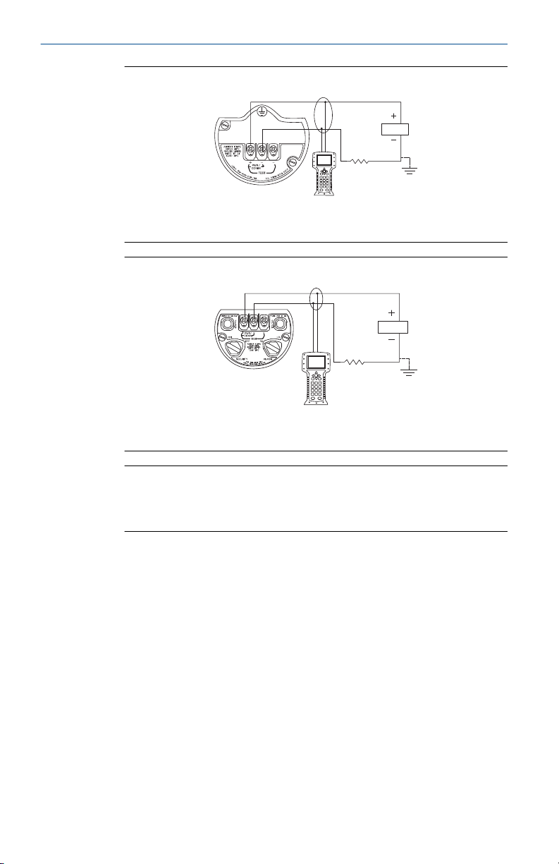
The figures below show the wiring connections necessary to power a
transmitter and enable communications with a hand-held Field
Communicator.
Quick Start Guide 15
Page 16
A
B
A
B
Quick Start Guide February 2019
Figure 5-1: Transmitter Wiring (Plantweb Housing)
A. RL ≥ 250 Ω
B. Power supply
Figure 5-2: Transmitter Wiring (Junction Box Housing)
A. RL ≥ 250 Ω
B. Power supply
Note
Installation of the transient protection terminal block does not provide
transient protection unless the Rosemount 3051S case is properly
grounded.
5.1
Ground signal wiring
Do not run signal wiring in conduit or open trays with power wiring, or near
heavy electrical equipment. Grounding terminations are provided on the
sensor module and inside the terminal compartment. These grounds are used
when transient protection terminal blocks are installed or to fulfill local
regulations.
Prerequisites
The cable shield should be:
• Trimmed close and insulated from touching the transmitter housing
• Continuously connected to the termination point
• Connected to a good earth ground at the power supply end
16 Rosemount 3051S Advanced HART
Page 17
DP
C
A
B
B
D
E
February 2019 Quick Start Guide
Procedure
1. Remove the field terminals housing cover.
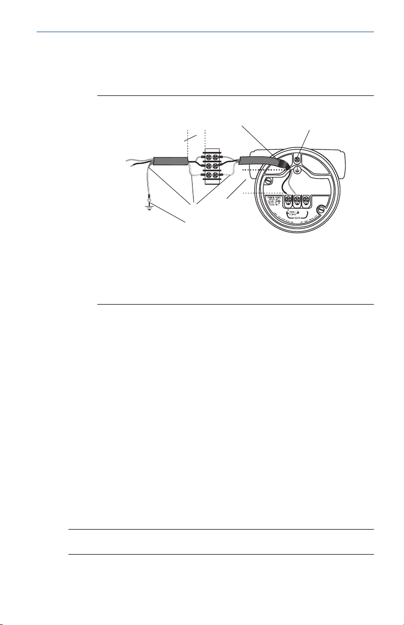
2. Connect the wiring pair and ground as shown.
Figure 5-3: Wiring
A. Insulate shield
B. Minimize distance
C. Connect shield back to the power supply ground
D. Trim shield and insulate
E. Ground for transient protection
3. Reinstall the housing cover so metal contacts metal to meet explosionproof requirements.
4. Plug and seal unused conduit connections with the provided conduit
plug.
5.2
Conduit electrical connector wiring (option GE or GM)
For Rosemount 3051S with conduit electrical connectors GE or GM, refer to
the cordset manufacturer’s installation instructions for wiring details. For FM
Intrinsically Safe, non-incendive or FM FISCO Intrinsically Safe hazardous
locations, install in accordance with Rosemount drawing 03151-1009 to
maintain outdoor rating (NEMA® 4X and IP66.) See Appendix B of the
Rosemount 3051S Reference Manual.
5.3
Power supply
The DC power supply should provide power with less than two percent ripple.
The total resistance load is the sum of the resistance of the signal leads and
the load resistance of the controller, indicator, and related pieces.
Note
The resistance of intrinsic safety barriers, if used, must be included.
Quick Start Guide 17
Page 18

1387
1000
500
0
10.5 20 30
42.4
Voltage (Vdc)
Load (Ohms)
Operating
Region
Quick Start Guide February 2019
Figure 5-4: Load Limitation
Maximum loop resistance = 43.5 x (power supply voltage – 10.5)
The Field Communicator requires a minimum loop resistance of 250Ω for
communication.
18 Rosemount 3051S Advanced HART
Page 19

February 2019 Quick Start Guide
6 Configuration verification
Use any HART®-compliant master to communicate with and verify
configuration of the transmitter with Advanced HART Diagnostics (option
code DA2).
A check (✓) indicates the basic configuration parameters. At a minimum,
these parameters should be verified as part of the configuration and startup
procedure.
Table 6-1: Fast Key Sequence
Function HART 7 Fast Keys HART 5 Fast Keys
Alarm and Saturation Levels 2, 2, 2, 5, 6 2, 2, 2, 5
Analog Output Trim 3, 4, 1, 2, 3 3, 4, 1, 2, 3
Burst Mode On/Off 2, 2, 5, 3, 1 2, 2, 5, 2, 1
Burst Options 2, 2, 5, 3 2, 2, 5, 2, 2
✓ Damping 2, 2, 1, 1, 3 2, 1, 1, 1, 3
Date 2, 1, 1, 1, 1, 5 2, 1, 1, 1, 1, 4
Descriptor 2, 1, 1, 1, 1, 3 2, 1, 1, 1, 1, 2
Digital To Analog Trim (4-20 mA Output) 3, 4, 1, 2, 3 3, 4, 1, 2, 3
Field Device Information 1, 7 1, 3, 5
HART Lock 2, 2, 6, 3 N/A
LCD Display Configuration 2, 1, 4 2, 1, 3, 1
Long Tag 2, 1, 1, 1, 1, 2 N/A
Loop Test 3, 5, 1 3, 5, 1
Lower Sensor Trim 3, 4, 1, 1, 1, 2 3, 4, 1, 1, 1, 2
Message 2, 1, 1, 1, 1, 4 2, 1, 1, 1, 1, 3
Process Alert Configuration 2, 1, 2, 3 2, 1, 2, 3
Poll Address 2, 2, 5, 2, 1 2, 2, 5, 3, 1
Remapping 2, 1, 1, 1, 4 2, 1, 1, 1, 4
Rerange- Keypad Input 2, 2, 2, 1 2, 2, 2, 1
Scaled Variable Configuration 2, 2, 3, 7 2, 2, 3, 5
View All Variables 1, 6 1, 3, 3
Sensor Trim 3, 4, 1, 1, 1 3, 4, 1, 1, 1
Status 1, 1 1, 1
Quick Start Guide 19
Page 20

Quick Start Guide February 2019
Table 6-1: Fast Key Sequence (continued)
Function HART 7 Fast Keys HART 5 Fast Keys
✓ Tag 2, 1, 1, 1, 1, 1 2, 1, 1, 1, 1, 1
✓ Transfer Function (Setting Output Type) 2, 2, 1, 1, 4 2, 2, 1, 1, 4
Transmitter Security (Write Protect) 2, 2, 6 2, 2, 6
✓ Units (Process Variable) 2, 1, 1, 1, 2 2, 1, 1, 1, 2
Upper Sensor Trim 3, 4, 1, 1, 1, 1 3, 4, 1, 1, 1, 1
Zero Trim 3, 4, 1, 1, 1, 3 3, 4, 1, 1, 1, 3
20 Rosemount 3051S Advanced HART
Page 21

February 2019 Quick Start Guide
7 Trim the transmitter
Transmitters are shipped fully calibrated per request or by the factory default
of full scale (lower range value = zero, upper range value = upper range limit).
7.1 Zero Trim
Prerequisites
Choose your trim procedure
1. Analog zero trim - sets the analog output to 4 mA.
a. Also referred to as a "rerange", it sets the lower value range
(LRV) equal to the measured pressure.
b. The display and digital HART output remains unchanged.
2. Digital zero trim - recalibrates the sensor zero.
a. The LRV is unaffected. The pressure value will be zero (on
display and HART output)/ 4 mA point may noy be at zero.
b. The transmitter must be within 3 percent of URL from factory
calibrated zero pressure in order to calibrate the zero function.
7.1.1 Use the Field Communicator
Fast Keys: 3, 4, 1, 1, 3
Procedure
1. Equalize or vent the transmitter and connect Field Communicator.
2. At the menu, input the Fast Key sequence.
3. Follow the commands to perform a zero trim.
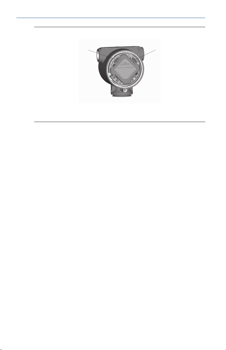
7.1.2 Use the transmitter zero adjustment button
This procedure is to adjust the lower range point (i.e. the pressure value
represented by 4 mA).
Procedure
Push and hold the zero adjustment button for at least two seconds but no
longer than ten seconds.
Quick Start Guide 21
Page 22
A B
Quick Start Guide February 2019
Figure 7-1: Transmitter Adjustment Buttons (Plantweb Housing)
A. Zero
B. Span
22 Rosemount 3051S Advanced HART
Page 23

February 2019 Quick Start Guide
8 Safety instrumented systems
For safety certified installations, refer to the “Advanced HART Diagnostic
Suite” section of the Rosemount 3051S Reference Manual for installation
procedures and system requirements specific to safety instrumented systems.
Quick Start Guide 23
Page 24

Quick Start Guide February 2019
9 Rosemount 3051S/3051SFx/3051S-ERS Product
Certifications
Rev 2.2
European Directive Information
A copy of the EU Declaration of Conformity can be found at the end of the
Quick Start Guide. The most recent revision of the EU Declaration of
Conformity can be found at Emerson.com/Rosemount.
Ordinary Location Certification
As standard, the transmitter has been examined and tested to determine that
the design meets the basic electrical, mechanical, and fire protection
requirements by a nationally recognized test laboratory (NRTL) as accredited
by the Federal Occupational Safety and Health Administration (OSHA).
Installing Equipment in North America
The US National Electrical Code® (NEC) and the Canadian Electrical Code (CEC)
permit the use of Division marked equipment in Zones and Zone marked
equipment in Divisions. The markings must be suitable for the area
classification, gas, and temperature class. This information is clearly defined in
the respective codes.
9.1 USA
9.1.1 E5 US Explosionproof (XP) and Dust-Ignitionproof (DIP)
Certificate
Standards
Markings
9.1.2 I5 US Intrinsic Safety (IS) and Nonincendive (NI)
Certificate
Standards
Markings
24 Rosemount 3051S Advanced HART
FM16US0090
FM Class 3600 - 2011, FM Class 3615 - 2006, FM Class 3616 2011, FM Class 3810 - 2005, ANSI/NEMA 250 - 2003
XP CL I, DIV 1, GP B, C, D; DIP CL II, DIV 1, GP E, F, G; CL III; T5(–
50 °C ≤ Ta ≤ +85 °C); Factory Sealed; Type 4X
FM16US0089X
FM Class 3600 - 2011, FM Class 3610 - 2010, FM Class 3611 2004, FM Class 3810 - 2005, NEMA® 250 - 2003
IS CL I, DIV 1, GP A, B, C, D; CL II, DIV 1, GP E, F, G; Class III; Class
1, Zone 0 AEx ia IIC T4; NI CL 1, DIV 2, GP A, B, C, D; T4(–50 °C ≤
Ta ≤ +70 °C) [HART]; T4(–50 °C ≤ Ta ≤ +60 °C) [Fieldbus]; when
connected per Rosemount drawing 03151-1006; Type 4X
Page 25

February 2019 Quick Start Guide
Special Condition for Safe Use:
1. The Model 3051S/3051S-ERS Pressure Transmitter contains aluminum
and is considered to constitute a potential risk of ignition by impact or
friction. Care must be taken into account during installation and use to
prevent impact and friction.
Note
Transmitters marked with NI CL 1, DIV 2 can be installed in Division 2 locations
using general Division 2 wiring methods or Nonincendive Field Wiring (NIFW).
See Drawing 03151-1006.
9.1.3 IE US FISCO Intrinsically Safe
9.2
Certificate
Standards
Markings
Special Condition for Safe Use:
1. The Rosemount 3051S/3051S-ERS Pressure Transmitter contains
Canada
FM16US0089X
FM Class 3600 - 2011, FM Class 3610 - 2010, FM Class 3611 2004, FM Class 3810 - 2005, NEMA 250 - 2003
IS CL I, DIV 1, GP A, B, C, D; T4(–50 °C ≤ Ta ≤ +60 °C); when
connected per Rosemount drawing 03151-1006; Type 4X
aluminum and is considered to constitute a potential risk of ignition by
impact or friction. Care must be taken into account during installation
and use to prevent impact and friction.
9.2.1 E6 Canada Explosionproof, Dust-Ignitionproof, and Division 2
Certificate
Standards
Markings
1143113
CAN/CSA C22.2 No. 0-10, CSA Std C22.2 No. 25-1966, CSA Std
C22.2 No. 30-M1986, CAN/CSA C22.2 No. 94-M91, CSA Std
C22.2 No. 142-M1987, CSA Std C22.2 No. 213-M1987,
ANSI/ISA 12.27.01-2003, CSA Std C22.2 No. 60529:05
Explosionproof Class I, Division 1, Groups B, C, D; DustIgnitionproof Class II, Division 1, Groups E, F, G; Class III; suitable
for Class I, Zone 1, Group IIB+H2, T5; suitable for Class I,
Division 2, Groups A, B, C, D; suitable for Class I, Zone 2, Group
IIC, T5; when connected per Rosemount drawing 03151-1013;
Type 4X
9.2.2 I6 Canada Intrinsically Safe
Certificate
Quick Start Guide 25
1143113
Page 26

Quick Start Guide February 2019
Standards
CAN/CSA C22.2 No. 0-10, CSA Std C22.2 No. 25-1966, CSA Std
C22.2 No. 30-M1986, CAN/CSA C22.2 No. 94-M91, CSA Std
C22.2 No. 142-M1987, CSA Std C22.2 No. 157-92, ANSI/ISA
12.27.01-2003, CSA Std C22.2 No. 60529:05
Markings
Intrinsically Safe Class I, Division 1; Groups A, B, C, D; suitable
for Class 1, Zone 0, IIC, T3C; when connected per Rosemount
drawing 03151-1016 [3051S] 03151-1313 [ERS]; Type 4X
9.2.3 IF Canada FISCO
Certificate
Standards
Markings
1143113
CAN/CSA C22.2 No. 0-10, CSA Std C22.2 No. 30-M1986,
CAN/CSA C22.2 No. 94-M91, CSA Std C22.2 No. 142-M1987,
CSA Std C22.2 No. 157-92, ANSI/ISA 12.27.01-2003, CSA Std
C22.2 No. 60529:05
FISCO Intrinsically Safe Class I, Division 1; Groups A, B, C, D;
suitable for Class 1, Zone 0, IIC, T3C; when connected per
Rosemount drawing 03151-1016 [3051S] 03151-1313 [ERS];
Type 4X
9.3 Europe
9.3.1 E1 ATEX Flameproof
Certificate
Standards
Markings
KEMA 00ATEX2143X
EN 60079-0:2012+A11:2013, EN 60079-1:2014, EN
60079-26:2015
II 1/2 G Ex db IIC T6…T4 Ga/Gb, T6(–60 °C ≤ Ta ≤ +70 °C), T5/
T4(–60 °C ≤ Ta ≤ +80 °C)
Table 9-1: Process Temperature
Temperature class Process temperature
T6 –60 °C to +70 °C
T5 –60 °C to +80 °C
T4 –60 °C to +120 °C
Special Conditions for Safe Use (X):
1. This device contains a thin wall diaphragm less than 1 mm thickness
that forms a boundary between Category 1 (process connection) and
Category 2 (all other parts of the equipment). The model code and
datasheet are to be consulted for details of the diaphragm material.
Installation, maintenance and use shall take into account the
26 Rosemount 3051S Advanced HART
Page 27

February 2019 Quick Start Guide
environmental conditions to which the diaphragm will be subjected.
The manufacturer's instructions for installation and maintenance shall
be followed in detail to assure safety during its expected lifetime.
2. Flameproof joints are not intended for repair.
3. Non-standard paint options may cause risk from electrostatic
discharge. Avoid installations that could cause electrostatic build-up
on painted surfaces, and only clean the painted surfaces with a damp
cloth. If paint is ordered through a special option code, contact the
manufacturer for more information.
4. Appropriate cable, glands and plugs need to be suitable for a
temperature of 5 °C greater than maximum specified temperature for
location where installed.
9.3.2 I1 ATEX Intrinsic Safety
Certificate
Standards
Markings
BAS01ATEX1303X
EN 60079-0: 2012+A11:2013, EN 60079-11: 2012
II 1 G Ex ia IIC T4 Ga, T4(–60 °C ≤ Ta ≤ +70 °C)
Table 9-2: Input Parameters
U
SuperModule 30 V 300 mA 1.0 W 30 nF 0
3051S...A; 3051SF…A;
3051SAL…C
3051S…F; 3051SF…F 30 V 300 mA 1.3 W 0 0
3051S …A…M7, M8, or
M9; 3051SF …A…M7,
M8, or M9;
3051SAL…C… M7, M8,
or M9
3051SAL or 3051SAM 30 V 300 mA 1.0 W 12 nF 33 µH
3051SAL…M7, M8, or
M9 3051SAM…M7,
M8, or M9
RTD Option for 3051SF 5 V 500 mA 0.63 W N/A N/A
i
30 V 300 mA 1.0 W 12 nF 0
30 V 300 mA 1.0 W 12 nF 60 µH
30 V 300 mA 1.0 W 12 nF 93 µH
I
i
P
i
C
i
L
i
Special Conditions for Safe Use (X):
1. The Model 3051S Transmitters fitted with transient protection are not
capable of withstanding the 500V test as defined in Clause 6.3.13 f EN
60079-11:2012. This must be taken into account during installation.
Quick Start Guide 27
Page 28
Quick Start Guide February 2019
2. The terminal pins of the Model 3051S SuperModule must be provided
with a degree of protection of at least IP20 in accordance with IEC/EN
60529.
3. The Model 3051S enclosure may be made of aluminum alloy and given
a protective polyurethane paint finish; however, care should be taken
to protect it from impact or abrasion if located in a zone 0 area.
9.3.3 IA ATEX FISCO
Certificate
Standards
Markings
BAS01ATEX1303X
EN 60079-0: 2012+A11:2013, EN 60079-11: 2012
II 1 G Ex ia IIC T4 Ga, T4(–60 °C ≤ Ta ≤ +70 °C)
Table 9-3: Input Parameters
Parameter FISCO
Voltage U
Current I
Power P
Capacitance C
Inductance L
i
i
i
i
i
17.5 V
380 mA
5.32 W
0
0
Special Conditions for Safe Use (X):
1. The Model 3051S Transmitters fitted with transient protection are not
capable of withstanding the 500 V test as defined in Clause 6.3.13 of
EN 60079-11:2012. This must be taken into account during
installation.
2. The terminal pins of the Model 3051S SuperModule must be provided
with a degree of protection of at least IP20 in accordance with IEC/EN
60529.
3. The Model 3051S enclosure may be made of aluminum alloy and given
a protective polyurethane paint finish; however, care should be taken
to protect it from impact or abrasion if located in a zone 0 area.
9.3.4 ND ATEX Dust
Certificate
Standards
Markings
28 Rosemount 3051S Advanced HART
BAS01ATEX1374X
EN 60079-0: 2012+A11:2013, EN 60079-31: 2009
II 1 D Ex ta IIIC T105 °C T
V
= 42.4 V
max
95 °C Da, (–20 °C ≤ T a ≤ +85 °C),
500
Page 29

February 2019 Quick Start Guide
Special Conditions for Safe Use (X):
1. Cable entries must be used which maintain the ingress protection of
the enclosure to at least IP66.
2. Unused cable entries must be filled with suitable blanking plugs which
maintain the ingress protection of the enclosure to at least IP66.
3. Cable entries and blanking plugs must be suitable for the ambient
temperature range of the apparatus and capable of withstanding a 7J
impact test.
4. The SuperModule(s) must be securely screwed in place to maintain the
ingress protection of the enclosure(s).
9.3.5 N1 ATEX Type n
Certificate
Standards
Markings
BAS01ATEX3304X
EN 60079-0: 2012+A11:2013, EN 60079-15: 2010
II 3 G Ex nA IIC T5 Gc, (–40 °C ≤ Ta ≤ +85 °C), V
Special Condition for Safe Use (X):
1. The equipment is not capable of withstanding the 500 V insulation test
required by clause 6.5 of EN 60079-15:2010. This must be taken into
account when installing the equipment.
Note
RTD Assembly is not included with the 3051SFx Type n Approval.
9.4
International
9.4.1 E7 IECEx Flameproof and Dust
Certificate
Standards
Markings
Table 9-4: Process Temperature
Temperature class Process temperature
T6 –60 °C to +70 °C
T5 –60 °C to +80 °C
T4 –60 °C to +120 °C
IECEx KEM 08.0010X (Flameproof)
IEC 60079-0:2011, IEC 60079-1:2014, IEC 60079-26:2014
Ex db IIC T6…T4 Ga/Gb, T6(–60 °C ≤ Ta ≤ +70 °C), T5/T4(–60 °C
≤ Ta ≤ +80 °C)
max
= 45 V
Quick Start Guide 29
Page 30

Quick Start Guide February 2019
Special Conditions for Safe Use (X):
1. This device contains a thin wall diaphragm less than 1 mm thickness
that forms a boundary between EPL Ga (process connection) and EPL
Gb (all other parts of the equipment). The model code and datasheet
are to be consulted for details of the diaphragm material. Installation,
maintenance and use shall take into account the environmental
conditions to which the diaphragm will be subjected. The
manufacturer's instructions for installation and maintenance shall be
followed in detail to assure safety during its expected lifetime.
2. Flameproof joints are not intended for repair.
3. Non-standard paint options may cause risk from electrostatic
discharge. Avoid installations that could cause electrostatic buildup on
painted surfaces, and only clean the painted surfaces with a damp
cloth. If paint is ordered through a special option code, contact the
manufacturer for more information.
4. Appropriate cable, glands and plugs need to be suitable for a
temperature of 5 °C greater than maximum specified temperature for
location where installed.
Certificate IECEx BAS 09.0014X (Dust)
Standards IEC 60079-0:2011, IEC 60079-31:2008
Markings Ex ta IIIC T105 °C T50095 °C Da, (–20 °C ≤ Ta ≤ +85 °C),
V
= 42.4 V
max
Special Conditions for Safe Use (X):
1. Cable entries must be used which maintain the ingress protection of
the enclosure to at least IP66.
2. Unused cable entries must be filled with suitable blanking plugs which
maintain the ingress protection of the enclosure to at least IP66.
3. Cable entries and blanking plugs must be suitable for the ambient
temperature range of the apparatus and capable of withstanding a 7J
impact test.
4. The 3051S- SuperModule must be securely screwed in place to
maintain the ingress protection of the enclosure.
9.4.2 I7 IECEx Intrinsic Safety
Certificate
Standards
Markings
30 Rosemount 3051S Advanced HART
IECEx BAS 04.0017X
IEC 60079-0: 2011, IEC 60079-11: 2011
Ex ia IIC T4 Ga, T4(–60 °C ≤ Ta ≤ +70 °C)
Page 31

February 2019 Quick Start Guide
Table 9-5: Input Parameters
U
SuperModule 30 V 300 mA 1.0 W 30 nF 0
3051S...A; 3051SF…A;
3051SAL…C
3051S…F; 3051SF…F 30 V 300 mA 1.3 W 0 0
3051S …A…M7, M8, or
M9; 3051SF …A…M7,
M8, or M9;
3051SAL…C… M7, M8,
or M9
3051SAL or 3051SAM 30 V 300 mA 1.0 W 12 nF 33 µH
3051SAL…M7, M8, or
M9 3051SAM…M7,
M8, or M9
RTD Option for 3051SF 5 V 500 mA 0.63 W N/A N/A
i
30 V 300 mA 1.0 W 12 nF 0
30 V 300 mA 1.0 W 12 nF 60 µH
30 V 300 mA 1.0 W 12 nF 93 µH
I
i
P
i
C
i
L
i
Special Conditions for Safe Use (X):
1. The Model 3051S Transmitters fitted with transient protection are not
capable of withstanding the 500 V test as defined in Clause 6.3.13 of
EN 60079-11:2012. This must be taken into account during
installation.
2. The terminal pins of the Model 3051S SuperModule must be provided
with a degree of protection of at least IP20 in accordance with IEC/EN
60529.
3. The Model 3051S enclosure may be made of aluminum alloy and given
a protective polyurethane paint finish; however, care should be taken
to protect it from impact or abrasion if located in a zone 0 area.
9.4.3 I7 IECEx Intrinsic Safety - Group I - Mining (I7 with Special A0259)
Certificate
Standards
Markings
Table 9-6: Input Parameters
U
SuperModule 30 V 300 mA 1.0 W 30 nF 0
Quick Start Guide 31
IECEx TSA 14.0019X
IEC 60079-0: 2011, IEC 60079-11: 2011
Ex ia I Ma (–60 °C ≤ Ta ≤ +70 °C)
i
I
i
P
i
C
i
L
i
Page 32

Quick Start Guide February 2019
Table 9-6: Input Parameters (continued)
U
3051S...A; 3051SF…A;
3051SAL…C
3051S…F; 3051SF…F 30 V 300 mA 1.3 W 0 0
3051S …A…M7, M8, or
M9; 3051SF …A…M7,
M8, or M9;
3051SAL…C… M7, M8,
or M9
3051SAL or 3051SAM 30 V 300 mA 1.0 W 12 nF 33 µH
3051SAL…M7, M8, or
M9 3051SAM…M7,
M8, or M9
RTD Option for 3051SF 5 V 500 mA 0.63 W N/A N/A
i
30 V 300 mA 1.0 W 12 nF 0
30 V 300 mA 1.0 W 12 nF 60 µH
30 V 300 mA 1.0 W 12 nF 93 µH
I
i
P
i
C
i
L
i
Special Conditions for Safe Use (X):
1. If the apparatus is fitted with optional 90 V transient suppressor, it is
not capable of withstanding the 500 V insulation test required by
Clause 6.3.13 of IEC60079-11. This must be taken into account when
installing the apparatus.
2. It is a condition of safe use that the above input parameters shall be
taken into account during installation.
3. It is a condition of manufacture that only the apparatus fitted with
housing, covers and sensor module housing made out of stainless
steel are used in Group I applications.
9.4.4 IG IECEx FISCO
Certificate
Standards
Markings
Table 9-7: Input Parameters
Parameter FISCO
Voltage U
Current I
Power P
Capacitance C
32 Rosemount 3051S Advanced HART
i
i
i
IECEx BAS 04.0017X
IEC 60079-0: 2011, IEC 60079-11: 2011
Ex ia IIC T4 Ga, T4(–60 °C ≤ Ta ≤ +70 °C)
17.5 V
380 mA
5.32 W
i
0
Page 33
February 2019 Quick Start Guide
Table 9-7: Input Parameters (continued)
Inductance L
i
0
Special Conditions for Safe Use (X):
1. The Model 3051S Transmitters fitted with transient protection are not
capable of withstanding the 500 V test as defined in Clause 6.3.13 of
EN 60079-11:2012. This must be taken into account during
installation.
2. The terminal pins of the Model 3051S SuperModule must be provided
with a degree of protection of at least IP20 in accordance with IEC/EN
60529.
3. The Model 3051S enclosure may be made of aluminum alloy and given
a protective polyurethane paint finish; however, care should be taken
to protect it from impact or abrasion if located in a zone 0 area.
9.4.5 IG IECEx Intrinsic Safety - Group I - Mining (IG with Special A0259)
Certificate
Standards
Markings
Table 9-8: Input Parameters
Parameter FISCO
Voltage U
Current I
Power P
Capacitance C
Inductance L
IECEx TSA 04.0019X
IEC 60079-0: 2011, IEC 60079-11: 2011
FISCO FIELD DEVICE Ex ia I Ma , (–60 °C ≤ Ta ≤ +70 °C)
i
i
i
i
i
17.5 V
380 mA
5.32 W
0
0
Special Conditions for Safe Use (X):
1. If the apparatus is fitted with optional 90 V transient suppressor, it is
not capable of withstanding the 500 V insulation test required by
Clause 6.3.13 of IEC60079-11. This must be taken into account when
installing the apparatus.
2. It is a condition of safe use that the above input parameters shall be
taken into account during installation.
3. It is a condition of manufacture that only the apparatus fitted with
housing, covers and sensor module housing made out of stainless
steel are used in Group I applications.
Quick Start Guide 33
Page 34

Quick Start Guide February 2019
9.4.6 N7 IECEx Type n
Certificate
Standards
Markings
Special Condition for Safe Use (X):
1. The equipment is not capable of withstanding the 500 V insulation test
required by clause 6.5 of EN 60079-15:2010. This must be taken into
account when installing the equipment.
IECEx BAS 04.0018X
IEC 60079-0: 2011, IEC 60079-15: 2010
Ex nA IIC T5 Gc,(–40 °C ≤ Ta ≤ +85 °C)
9.5 Brazil
9.5.1 E2 INMETRO Flameproof
Certificate
Standards
Markings
Special Conditions for Safe Use (X):
1. The device contains a thin wall diaphragm less than 1mm thick that
UL-BR15.0393X
ABNT NBR IEC 60079-0:2008 + Corrigendum 1:2011, ABNT NBR
IEC 60079-1:2009 + Corrigendum 1:2011, ABNT NBR IEC
60079-26:2008 + Corrigendum 1: 2008
Ex db IIC T* Ga/Gb, T6(–60 °C ≤ Ta ≤ +70 °C), T5/T4(–60 °C ≤ Ta ≤
+80 °C), IP66
forms a boundary between zone 0 (process connection) and zone 1 (all
other parts of the equipment).The model code and datasheet are to be
consulted for details of the diaphragm material. Installation,
maintenance, and use shall take into account the environmental
conditions to which the diaphragm will be subjected. The
manufacturer's instructions for maintenance shall be followed in detail
to assure safety during its expected lifetime.
2. Flameproof joints are not intended for repair.
3. Non-standard paint options may cause risk from electrostatic
discharge. Avoid installations that could cause electrostatic buildup on
painted surfaces, and only clean the painted surfaces with a damp
cloth. If paint is ordered through a special option code, contact the
manufacturer for more information.
9.5.2 I2/IB INMETRO Intrinsic Safety/FISCO
Certificate
Standards
34 Rosemount 3051S Advanced HART
UL-BR 15.0392X
ABNT NBR IEC 60079-0:2013, ABNT NBR IEC 60079-11:2013
Page 35

February 2019 Quick Start Guide
Markings
Ex ia IIC T4 Ga (–60 °C ≤ Ta ≤ +70 °C), IP66
Special Conditions for Safe Use (X):
1. The surface resistivity of the antenna is greater than 1 GΩ. To avoid
electrostatic charge buildup, it must not be rubbed or cleaned with
solvents or a dry cloth.
2. The Model 701PBKKF Power Module may be replaced in a hazardous
area. The Power Module has a surface resistivity greater than 1 GΩ and
must be properly installed in the wireless device enclosure. Care must
be taken during transportation to and from the point of installation to
prevent electrostatic charge buildup.
3. The 3051S enclosure may be made of aluminium alloy and given a
protective polyurethane paint finish; however, care should be taken to
protect it from impact or abrasion if located in areas that requires EPL
Ga.
Table 9-9: Input Parameters
U
SuperModule 30 V 300 mA 1.0 W 30 nF 0
3051S...A; 3051SF…A;
3051SAL…C
3051S…F; 3051SF…F 30 V 300 mA 1.3 W 0 0
3051S…F…IB;
3051SF…F…IB
3051S …A…M7, M8, or
M9; 3051SF …A…M7,
M8, or M9;
3051SAL…C… M7, M8,
or M9
3051SAL or 3051SAM 30 V 300 mA 1.0 W 12 nF 33 µH
3051SAL… M7, M8, or
M9 3051SAM… M7,
M8, or M9
RTD Option for 3051SF 5 V 500 mA 0.63 W N/A N/A
i
30 V 300 mA 1.0 W 12 nF 0
17.5 V 380mA 5.32W 0 0
30 V 300 mA 1.0 W 12 nF 60 µH
30 V 300 mA 1.0 W 12 nF 93 µH
I
i
P
i
C
i
L
i
9.6 China
9.6.1 E3 China Flameproof and Dust Ignition-proof
Certificate
Quick Start Guide 35
3051S: GYJ16.1249X
3051SFx: GYJ16.1466X
Page 36

Quick Start Guide February 2019
3051S-ERS: GJY15.1406X
Standards
3051S: GB3836.1-2010, GB3836.2-2010, GB3836.20-2010,
GB12476.1-2013, GB12476.5-2013
3051SFx: GB3836.1-2010, GB3836.2-2010, GB3836.20-2010,
GB12476.1-2013, GB 12476.5-2013
3051S-ERS: GB3836.1-2010, GB3836.2-2010, GB3836.20-2010
Markings
3051S: Ex d IIC T6…T4; Ex tD A20 T105 °C T
95 °C; IP66
500
3051SFx: Ex d IIC T4~T6 Ga/Gb; Ex tD A20 IP66 T105 °CT
500
95
°C; IP66
3051S-ERS: Ex d IIC T4~T6 Ga/Gb
9.6.2 I3 China Intrinsic Safety
Certificate
3051S: GYJ16.1250X[Mfg USA, China, Singapore]
3051SFx: GYJ16.1465X [Mfg USA, China, Singapore]
3051S-ERS: GYJ16.1248X [Mfg USA, China, Singapore]
Standards
3051S: GB3836.1-2010, GB3836.4-2010, GB3836.20-2010
3051SFx: GB3836.1/4-2010, GB3836.20-2010,
GB12476.1-2013, GB12476.5-2013
3051S-ERS: GB3836.1-2010, GB3836.4-2010, GB3836.20-2010
Markings
3051S: Ex ia IIC T4 Ga
3051SFx: Ex ia IIC T4 Ga, Ex tD A20 IP66 T105 °CT
500
95 °C
3051S-ERS: Ex ia IIC T4 Ga
9.6.3 N3 China Type n
Certificate
Markings
3051S, 3051SHP: GYJ17.1354X
3051SFX: GYJ17.1355X
Ex nA IIC T5 Gc
9.7 EAC - Belarus, Kazakhstan, Russia
9.7.1 EM Technical Regulation Customs Union (EAC) Flameproof and Dust Ignition-proof
Certificate
Markings
RU C-US.AA87.B.00378
Ga/Gb Ex d IIC T6…T4 X
Ex tb IIIC T105 °C T
Ex ta IIIC T105 °C T
500
95 °C Da X
500
95 °C Db X
36 Rosemount 3051S Advanced HART
Page 37

February 2019 Quick Start Guide
9.7.2 IM Technical Regulation Customs Union (EAC) Intrinsic Safety
Certificate
Markings
RU C-US.AA87.B.00378
0Ex ia IIC T4 Ga X
9.7.3 IN Technical Regulation Customs Union (EAC) Intrinsic Safety
Certificate:
Markings:
RU C-US.AA87.B.00378
0Ex ia IIC T4 Ga X
9.8 Japan
9.8.1 E4 Japan Flameproof
Certificate
Markings
Temperature class Ambient temperature Process temperature
T6 -40 °C to +70 °C -60 °C to +70 °C
Special Conditions for Safe Use:
1. This device contains a thin wall diaphragm less than 1mm thickness
TC15682, TC15683, TC15684, TC15685, TC15686, TC15687,
TC15688, TC15689, TC15690, TC17099, TC17100, TC17101,
TC17102, TC18876
3051ERS: TC20215, TC20216, TC20217, TC20218, TC20219,
TC20220, TC20221
Ex d IIC T6 Ga/Gb
that forms a boundary between EPL Ga (process connection) and EPL
Gb (all other parts of the equipment). The model code and datasheet
are to be consulted for details of the diaphragm material. Installation,
maintenance, and use shall consider the environmental conditions to
which the diaphragm will be subjected. The manufacturer’s
instructions fr installation and maintenance shall be followed in detail
to assure safety during its expected lifetime.
2. Flameproof joints are not intended for repair.
3. Non-standard paint options may cause risk from electrostatic
discharge. Avoid installations that could cause electrostatic build-up
on painted surfaces, and only clean the painted surfaces with a damp
cloth. If paint is ordered through a special option code, contact the
manufacturer for more information.
Quick Start Guide 37
Page 38

Quick Start Guide February 2019
9.9 Republic of Korea
9.9.1 EP Republic of Korea Flameproof
Certificate
Markings
12-KB4BO-0180X [Mfg USA], 11-KB4BO-0068X [Mfg
Singapore]
Ex d IIC T6...T4
9.9.2 IP Republic of Korea Intrinsic Safety
Certificate
Markings
12-KB4BO-0202X [HART - Mfg USA],12-KB4BO-0204X [Fieldbus
- Mfg USA], 12-KB4BO-0203X [HART - Mfg Singapore], 13KB4BO-0296X [Fieldbus - Mfg Singapore]
Ex ia IIC T4
9.10 Combinations
K1
K2
K5
K6
K7
KA
KB
KC
KD
KG
KM
KP
Combination of E1, I1, N1, and ND
Combination of E2 and I2
Combination of E5 and I5
Combination of E6 and I6
Combination of E7, I7, and N7
Combination of E1, I1, E6, and I6
Combination of E5, I5, E6, and I6
Combination of E1, I1, E5, and I5
Combination of E1, I1, E5, I5, E6, and I6
Combination of IA, IE, IF, and IG
Combination of EM and IM
Combination of EP and IP
9.11 Additional Certifications
9.11.1 SBS American Bureau of Shipping (ABS) Type Approval
Certificate
Intended Use
38 Rosemount 3051S Advanced HART
17-RJ1679518-PDA
Measure gauge or absolute pressure of liquid, gas or vapor
applications on ABS classed vessels, marine, and offshore
installations.
Page 39

February 2019 Quick Start Guide
9.11.2 SBV Bureau Veritas (BV) Type Approval
Certificate
Requirements
Application
31910 BV
Bureau Veritas Rules for the Classification of Steel Ships
Class Notations: AUT-UMS, AUT-CCS, AUT-PORT and AUTIMS.
9.11.3 SDN Det Norske Veritas (DNV) Type Approval
Certificate
Intended Use
Application
Location classes
Type 3051S
Temperature D
Humidity B
Vibration A
EMC A
Enclosure D/IP66/IP68
TAA00000K9
Det Norske Veritas' Rules for Classification of Ships, High
Speed & Light Craft, and Det Norske Veritas' Offshore
Standards
9.11.4 SLL Lloyds Register (LR) Type Approval
Certificate
Application
11/60002
Environmental categories ENV1, ENV2, ENV3, and ENV5
9.11.5 D3 Custody Transfer - Measurement Canada Accuracy Approval [3051S Only]
Certificate
Quick Start Guide 39
AG-0501, AV-2380C
Page 40

EU Declaration of Conformity
No: RMD 1044 Rev. AD
Page 1 of 4
We,
Rosemount Inc.
8200 Market Boulevard
Chanhassen, MN 55317-9685
USA
declare under our sole responsibility that the product,
Rosemount 3051S Series Pressure Transmitters
Rosmeount 3051SFx Series Flowmeter Transmitters
Rosemount 300S Housings
manufactured by,
Rosemount Inc.
8200 Market Boulevard
Chanhassen, MN 55317-9685
USA
to which this declaration relates, is in conformity with the provisions of the European Union
Directives, including the latest amendments, as shown in the attached schedule.
Assumption of conformity is based on the application of the harmonized standards and, when
applicable or required, a European Union notified body certification, as shown in the attached
schedule.
(signature)
Vice President of Global Quality
(function name - printed)
Chris LaPoint
(name - printed)
1-Feb-19; Shakopee, MN USA
(date of issue)
Quick Start Guide February 2019
10 Rosemount 3051S Declaration of Conformity
40 Rosemount 3051S Advanced HART
Page 41

EU Declaration of Conformity
No: RMD 1044 Rev. AD
Page 2 of 4
EMC Directive (2014/30/EU)
Harmonized Standards:
EN 61326-1:2013, EN 61326-2-3:2013
PED Directive (2014/68/EU)
Rosemount 3051S Series Pressur e Tr ansmitters
Rosemount 3051S_CA4; 3051S_CD2, 3, 4, 5 (also with P0 & P9 option) Pressure
Transmitters
QS Certificate of Assessment – Certificate No. 12698-2018-CE-USA-ACCREDIA
Module H Conformity Assessment
Other Standards Used: ANSI / ISA 61010-1:2004
Note – previous PED Certificate No. 59552-2009-CE-HOU-DNV
All other Rosemount 3051S Pressure Transmitters
Sound Engineering Practice
Transmitter Attachments: Diaphragm Seal, Process Flange, or Manifold
Sound Engineering Practice
Rosemount 3051SFx Series Flowmeter Pressure Tran smitters
See DSI 1000 Declaration of Conformity
February 2019 Quick Start Guide
Quick Start Guide 41
Page 42

EU Declaration of Conformity
No: RMD 1044 Rev. AD
Page 3 of 4
ATEX Directive (2014/34/EU)
BAS01ATEX1303X – Intrinsic Safety Certificate
Equipment Group II, Category 1 G
Ex ia IIC T4 Ga
Harmonized Standards Used:
EN 60079-0:2012+A11:2013, EN 60079-11:2012
BAS01ATEX3304X – Type n Certificate
Equipment Group II, Category 3 G
Ex nA IIC T5 Gc
Harmonized Standards Used:
EN 60079-0:2012+A11:2013, EN 60079-15:2010
BAS01ATEX1374X – Dust Certificate
Equipment Group II, Category 1 D
Ex ta IIIC T105°C T
500
95°C Da
Harmonized Standards Used:
EN 60079-0:2012+A11:2013
Other Standards Used:
EN 60079-31:2009 (a review against EN 60079-31:2014, which is
harmonized, shows no significant changes relevant to this equipment
so EN 60079-31:2009 continues to represent “State of the Art”)
BAS04ATEX0181X – Mining Certificate
Equipment Group I, Category M1
Ex ia I Ma
Harmonized Standards Used:
EN 60079-0:2012, EN 60079-11:2012
BAS04ATEX0193U – Mining Certificate: Component
Equipment Group I, Category M1
Ex ia I Ma
Harmonized Standards Used:
EN 60079-0:2012, EN 60079-11:2012
KEMA00ATEX2143X – Flameproof Certificate
Equipment Group II, Category 1/2 G
Ex db IIC T6…T4 Ga/Gb
Harmonized Standards:
EN 60079-0:2012+A11:2013, EN 60079-1:2014, EN 60079-26:2015
Quick Start Guide February 2019
42 Rosemount 3051S Advanced HART
Page 43

EU Declaration of Conformity
No: RMD 1044 Rev. AD
Page 4 of 4
PED Notified Body
DNV GL Business Assurance Italia S.r.l. [Notified Body Number: 0496]
Via Energy Park, 14, N-20871
Vimercate (MB), Italy
Note – equipment manufactured prior to 20 October 2018 may be marked with the previous PED
Notified Body number; previous PED Notified Body information was as follows:
Det Norske Veritas (DNV) [Notified Body Number: 0575]
Veritasveien 1, N-1322
Hovik, Norway
ATEX Notified Bodies for EU Type Examination Certificate
DEKRA Certification B.V. [Notified Body Number: 0344]
Utrechtseweg 310
Postbus 5185
6802 ED Arnhem
Netherlands
SGS FIMCO OY [Notified Body Number: 0598]
P.O. Box 30 (Särkiniementie 3)
00211 HELSINKI
Finland
ATEX Notified Body for Quality Assurance
SGS FIMCO OY [Notified Body Number: 0598]
P.O. Box 30 (Särkiniementie 3)
00211 HELSINKI
Finland
February 2019 Quick Start Guide
Quick Start Guide 43
Page 44

ᴹ
China RoHS
㇑᧗⢙䍘䎵䗷ᴰབྷ⎃ᓖ䲀٬Ⲵ䜘Ԧරࡇ㺘
Rosemount 3051S
List of Rosemount 3051S Parts with China RoHS Concentration above MCVs
䜘Ԧ〠
Part Name
ᴹᇣ⢙䍘
/ Hazardous Substances
䫵
Lead
(Pb)
⊎
Mercury
(Hg)
䭹
Cadmium
(Cd)
ޝԧ䬜
Hexavalent
Chromium
(Cr +6)
ཊⓤ㚄㤟
Polybrominated
biphenyls
(PBB)
ཊⓤ㚄㤟䟊
Polybrominated
diphenyl ethers
(PBDE)
⭥ᆀ㓴Ԧ
Electronics
Assembly
X O O O O O
༣փ㓴Ԧ
Housing
Assembly
X O O X O O
Րᝏಘ㓴Ԧ
Sensor
Assembly
X O O X O O
ᵜ㺘Ṭ㌫ᦞ
SJ/T11364
Ⲵ㿴ᇊ㘼ࡦ
This table is proposed in accordance with the provision of SJ/T11364.
O:
Ѫ䈕䜘ԦⲴᡰᴹ൷䍘ᶀᯉѝ䈕ᴹᇣ⢙䍘Ⲵ䟿൷վҾ
GB/T 26572
ᡰ㿴ᇊⲴ䲀䟿㾱≲
O: Indicate that said hazardous substance in all of the homogeneous materials for this part is below the limit requirement of
GB/T 26572.
X:
Ѫ൘䈕䜘Ԧᡰ֯⭘Ⲵᡰᴹ൷䍘ᶀᯉ䟼ˈ㠣ቁᴹа㊫൷䍘ᶀᯉѝ䈕ᴹᇣ⢙䍘Ⲵ䟿儈Ҿ
GB/T 26572
ᡰ㿴ᇊⲴ䲀䟿㾱≲
X: Indicate that said hazardous substance contained in at least one of the homogeneous materials used for this part is above
the limit requirement of GB/T 26572.
Quick Start Guide February 2019
11 China RoHS
44 Rosemount 3051S Advanced HART
Page 45

February 2019 Quick Start Guide
Quick Start Guide 45
Page 46

Quick Start Guide February 2019
46 Rosemount 3051S Advanced HART
Page 47

February 2019 Quick Start Guide
Quick Start Guide 47
Page 48

*00825-0300-4801*
00825-0300-4801, Rev. DA
Quick Start Guide
February 2019
Global Headquarters
Emerson Automation Solutions
6021 Innovation Blvd.
Shakopee, MN 55379, USA
+1 800 999 9307 or +1 952 906 8888
+1 952 949 7001
[email protected]
Latin America Regional Office
Emerson Automation Solutions
1300 Concord Terrace, Suite 400
Sunrise, FL 33323, USA
+1 954 846 5030
+1 954 846 5121
[email protected]
Asia Pacific Regional Office
Emerson Automation Solutions
1 Pandan Crescent
Singapore 128461
+65 6777 8211
+65 6777 0947
[email protected]
North America Regional Office
Emerson Automation Solutions
8200 Market Blvd.
Chanhassen, MN 55317, USA
+1 800 999 9307 or +1 952 906 8888
+1 952 949 7001
[email protected]
Europe Regional Office
Emerson Automation Solutions Europe
GmbH
Neuhofstrasse 19a P.O. Box 1046
CH 6340 Baar
Switzerland
+41 (0) 41 768 6111
+41 (0) 41 768 6300
[email protected]
Middle East and Africa Regional Office
Emerson Automation Solutions
Emerson FZE P.O. Box 17033
Jebel Ali Free Zone - South 2
Dubai, United Arab Emirates
+971 4 8118100
+971 4 8865465
[email protected]
Linkedin.com/company/Emerson-
Automation-Solutions
Twitter.com/Rosemount_News
Facebook.com/Rosemount
Youtube.com/user/
RosemountMeasurement
Google.com/+RosemountMeasurement
©
2019 Emerson. All rights reserved.
Emerson Terms and Conditions of Sale are
available upon request. The Emerson logo is a
trademark and service mark of Emerson Electric
Co. Rosemount is mark of one of the Emerson
family of companies. All other marks are the
property of their respective owners.
Loading...