

Page 1

Quick Start Guide
00825-0200-4410, Rev EC
February 2019
Emerson™ Wireless 1410 A/B and 1410D Gateway with 781 Field Link
Page 2

Quick Start Guide
February 2019
NOTICE
This guide provides basic guidelines for the Emerson Wireless 1410 and 1410D Gateway. It does not provide
instructions for diagnostics, maintenance, service, or troubleshooting. Refer to the Emerson Wireless Gateway
1410 Reference Manual
electronically on Emerson.com/Rosemount
This device complies with Part 15 of the FCC Rules. Operation is subjec t to the following conditions. This device
may not cause harmful interference. This device must accept any interference received, including interference
that may cause undesired operation. This device must be installed to ensure a minimum antenna separation
distance of 20 cm from all persons.
Explosion hazard
Do not make or break any connections to the Gateway while circuits are live unless area is known to be
non-hazardous.
Explosions could result in death or serious injury.
Installation of this device in an explosive environment must be in accordance with the appropriate local,
national, and international standards, codes, and practices. Review the Product Certifications section for any
restrictions associated with a safe installation.
Avoid contact with the leads and terminals. High voltage that may be present on leads can cause electrical
shock.
Potential electrostatic charging hazard
The Gateway enclosure is plastic. Use care in handling and cleaning when in explosive environments to avoid
an electrostatic discharge.
for more information and instructions. The manuals and this guide are available
.
Contents
Wireless planning . . . . . . . . . . . . . . . . . . . . . . . . 3
PC requirements . . . . . . . . . . . . . . . . . . . . . . . . . 3
Initial connection and configuration . . . . . . . . 3
Physical installation . . . . . . . . . . . . . . . . . . . . . . 11
2
Software installation (optional) . . . . . . . . . . . 20
Verify operations . . . . . . . . . . . . . . . . . . . . . . . . 21
Product Certification . . . . . . . . . . . . . . . . . . . . 23
Page 3

February 2019
1.0 Wireless planning
1.1 Power up sequence
The Gateway should be installed and functioning properly before power
modules are installed in any wireless field devices. Wireless field devices should
also be powered up in order of proximity from the Gateway beginning with the
closest. This will result in a simpler and faster network installation.
1.2 Antenna position
The antenna should be positioned vertically and be approximately 6 ft. (2 m)
from large structures or buildings to allow for clear communication to other
devices.
1.3 Mounting height
For optimal wireless coverage, the remote antenna is ideally mounted 15–25 ft.
(4.6–7.6 m) above ground or 6 ft. (2 m) above obstructions or major
infrastructure.
2.0 PC requirements
Quick Start Guide
2.1 Operating system (optional software only)
Microsoft
Windows Server 2008 R2 Standard Edition, Service Pack 1
Windows 7 Professional, Service Pack 1
Windows 7 Enterprise, Service Pack 1
Windows 8 Enterprise, Service Pack 1
Windows 10 Enterprise, Service Pack 1
®
Windows™ Server 2008 (Standard Edition), Service Pack 2
2.2 Applications
Configuration of the Gateway is done through a secure web interface. Recent
versions of the following browsers are supported:
Internet Explorer
Chrome
Mozilla Firefox
Microsoft Edge
™
®
browser
®
2.3 Hard disk space
AMS Wireless Configurator: 1.5 GB
Gateway Setup CD: 250 MB
3.0 Initial connection and configuration
To configure the Gateway, a local connection between a PC/Mac/laptop and the
Gateway needs to be established. The Emerson 1410 and 1410D are
operationally equivalent and the following instructions are applicable to both
models.
3
Page 4

Quick Start Guide
3.1 Powering the Gateway
For both Emerson Wireless 1410A/B and the 1410D, bench top power will be
needed to power the Gateway by wiring a 10.5–30 VDC (20–30 VDC if a 781 is
connected with I.S. barriers to the Emerson 1410D) power source, with a
capacity of at least 250 mA to the power terminals.
Figure 1. Emerson 1410A/B Gateway Housing
A
B
February 2019
Power
Reset
C
D
E
Power Input
+
24 VDC
(nominal)
-
S
Serial
Modbus
A+
B-
F
A. DIN Rail clip
B. SMA to N type connection
C. Power light. During normal operation the power indicator will be green.
D. Ethernet port 2. When this port is activated, the factory IP address is 192.168.2.10. See
Table 1 on page 9.
E. Ethernet port 1. Use for standard communication to the webserver or other protocols
enabled on the Gateway. The factory IP address is 192.168.1.10. See Table 1 on page 9.
F. Emerson 1410 power and serial connection. Black terminal included in the box.
4
Page 5

February 2019
Figure 2. Emerson 1410D Gateway Wiring
E
Quick Start Guide
A
B
E
C
D
F
F
A. DIN Rail Clip
B. Power light. During normal operation the power indicator will be green.
C. Ethernet port 2. When this port is activated, the factory IP address is 192.168.2.10. See
Table 1 on page 9.
D. Ethernet port 1. When this port is activated, the factory IP address is 192.168.1.10. See
Table 1 on page 9.
E. Emerson 1410 Power and Serial connections. Black terminal included in the box.
F. Emerson Wireless 781 Field Link power and data connections. Black terminal included in
box.
5
Page 6

Quick Start Guide
3.2 Establishing a connection
Connect the PC/laptop to the Ethernet 1 (Primary) receptacle on the Gateway
using an Ethernet cable.
Windows 7
1. Click the Internet Access icon on the bottom right of the screen.
Figure 3. Internet Access
2. Select the Network and Sharing Center.
3. Select Local Area Connection.
February 2019
Figure 4. Local Area Connection
4. Select Properties.
6
Page 7

February 2019
5. Select Internet Protocol Version 4 (TCP/IPv4) then select Properties.
Figure 5. Internet Protocol Version 4 (TCP/IPv4)
Note
If the PC/laptop is from another network, record the current IP address and other settings
so the PC/laptop can be returned to the original network after the Gateway has been
configu red.
Quick Start Guide
6. Select the Use the following IP address button.
Figure 6. IP Address
7. In the IP address field, enter 192.168.1.12 (DeltaV Ready enter 10.5.255.12).
8. In the Subnet mask field, enter 255.255.255.0.
7
Page 8

Quick Start Guide
1
2
9. Select OK for both the Internet Protocol (TCP/IP) Properties window and the
Local Area Connection Properties window.
Windows 10
1. Select the network icon in the lower right corner.
2. Select the Network settings link.
3. Select Ethernet on the left hand side of the Network Settings dialog.
February 2019
8
Page 9

February 2019
4. Select Change adapter options.
5. See steps 4-10 from Windows 7 instructions.
Note
Connecting to the Gateway's secondary Ethernet port will require different network
settings.
Table 1. TCP/IP Network Settings
Quick Start Guide
Gateway PC/laptop/tablet Subnet
Ethernet 1 192.168.1.10 192.168.1.12 255.255.255.0
Ethernet 2 192.168.2.10 192.168.2.12 255.255.255.0
Disable proxies
1. Open web browser.
2. Navigate Tools >I nternet Options > Connections > LAN Settings (may be a
different process for other browsers).
3. Under Proxy server, uncheck the Use a proxy server... box.
9
Page 10
Quick Start Guide
3.3 Configure the Gateway
To complete initial configuration for the Gateway:
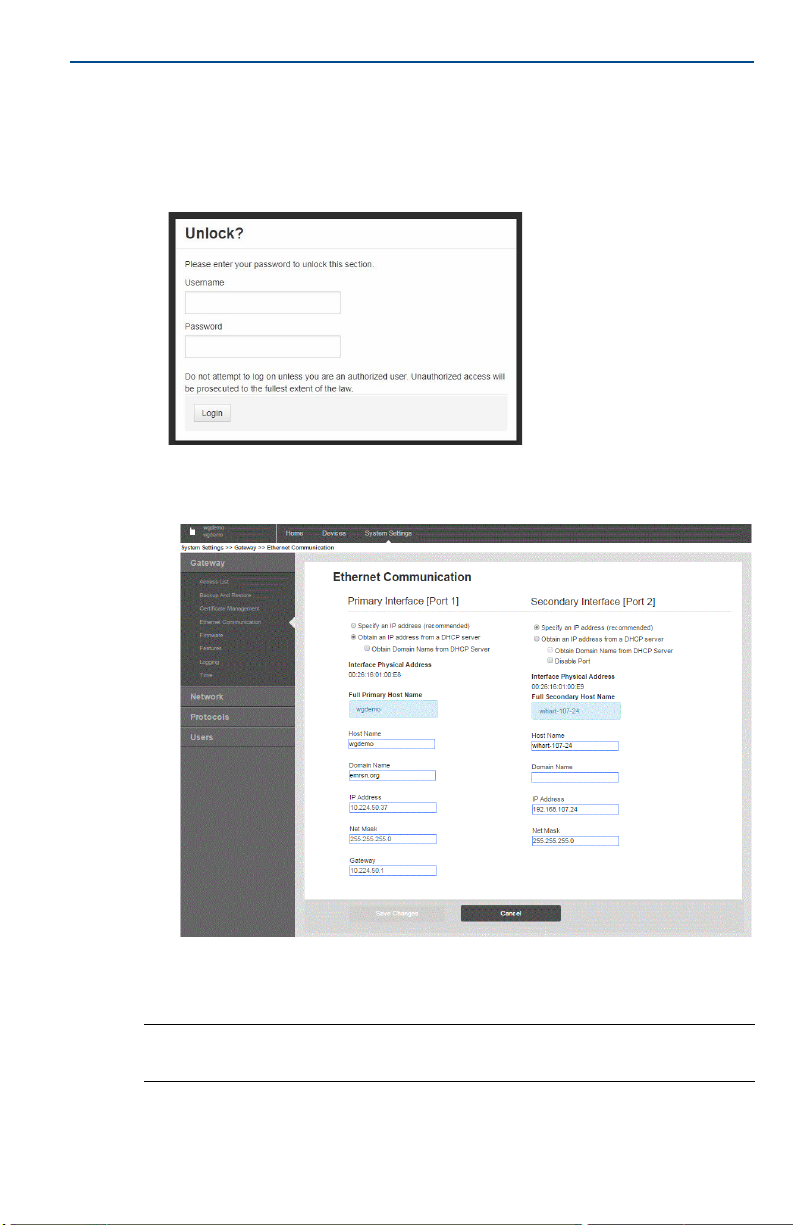
1. Access the default web page for the Gateway at https://192.168.1.10
a. Log on as Username: admin
b. Type in password: default
2. Navigate to System Settings > Gateway > Ethernet Communication to enter the
Network Settings.
a. Configure a static IP Address or set for DHCP and enter a Hostname.
February 2019
10
b. Restart application at System Settings > Gateway > Backup and Restore >
Restart Apps.
Note
Resetting applications will temporarily disable communications with field devices.
3. Disconnect the power and Ethernet cable from the Gateway.
Page 11
February 2019
4.0 Physical installation
4.1 Emerson 1410A/B and 1410D mounting
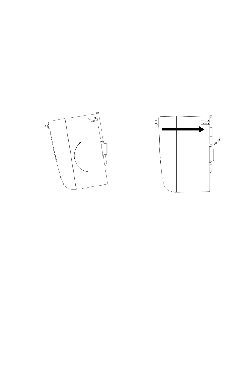
The unit can be snapped onto a DIN TS35/7.5 or TS35/15 rail system. To clip the
unit onto the DIN rail, see Figure 7.
1. Tilt the unit at a slight angle allowing the lower lip of the chassis to catch the
bottom of the DIN rail.
2. Apply pressure forward to snap the back of the unit securely onto the DIN
rail.
Figure 7. Installing
Quick Start Guide
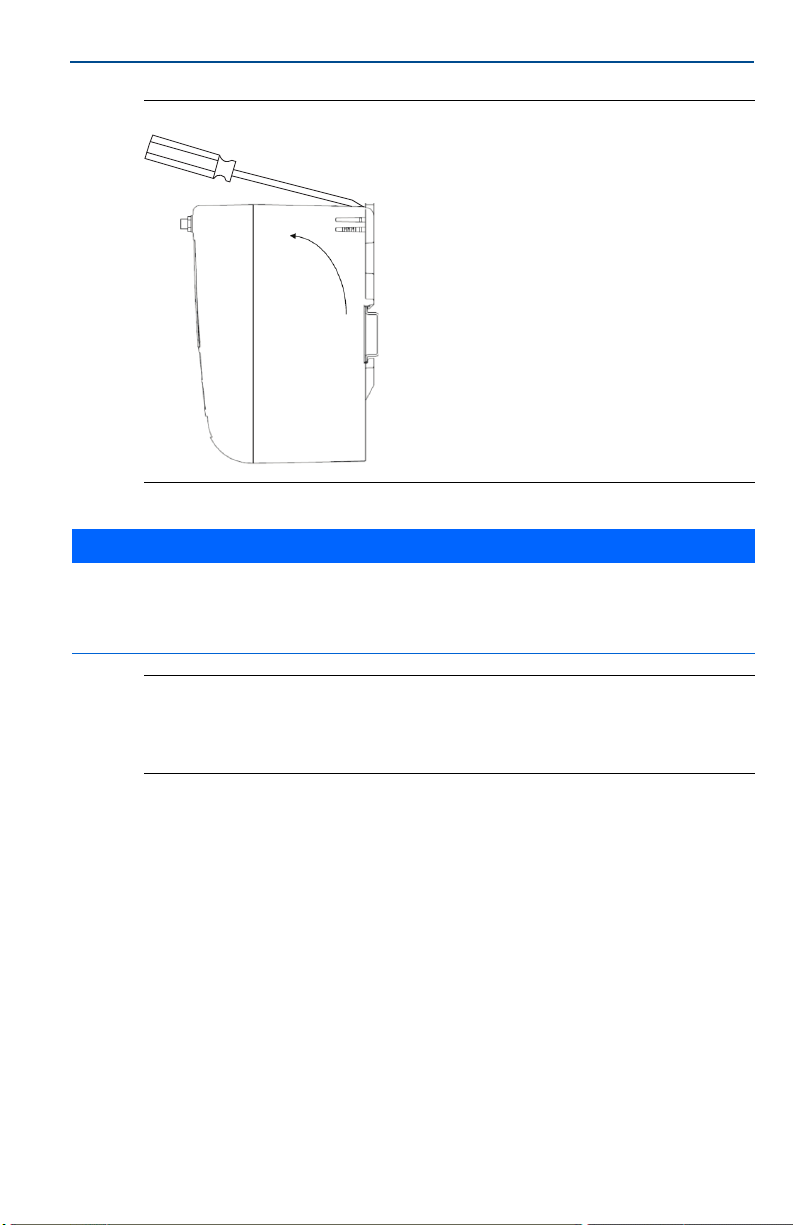
To remove the unit, see Figure 8.
1. Place a flat or rounded object (such as a screw driver) into the DIN clip and
apply a slight pressure downwards on the object.
2. Once the unit is released from the DIN rail, pull backwards and down to
successfully disengage.
11
Page 12
Quick Start Guide
February 2019
Figure 8. Removing
NOTICE
When mounting the unit in an electrical enclosure or other location, comply with the appropriate local and
national installation codes. Verify that the installer, associated hardware, and installation equipment used have
the proper certifications for the specific type of installation being performed. Before installation, verif y if local
codes require a permit and/or an inspection before energizing. When planning the installation, account for
routing the antenna cable within the enclosure.
Note
Do not mount the antenna within a metal enclosure. To avoid damage to sensitive RF
components, do not remove protective cap from the Gateway SMA connector until ready
to install the antenna.
4.2 Connecting the Emerson 1410D with 781
There are two main connection configurations for the Emerson 1410D and 781:
with and without barriers. The location and hazardous approval option of the
Emerson 781 determines whether it needs to be installed with barriers.
12
Page 13
February 2019
Data A (+)
Data B (-)
Return (-)
24 VDC (+)
Blu
Wht
Red
Blk
C
E
D
B
A
Red
Blk
Blu
Wht
10.5-30VDC
Gray line means internal
connection
Installation without barriers
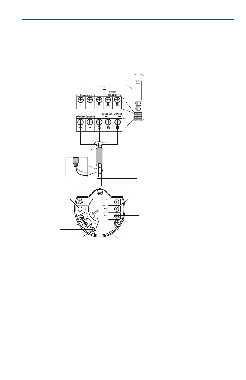
A shielded twisted pair cable is needed for connecting the Emerson 1410D and
781 (refer to Figure 9). The Emerson 781 can be located up to 656 ft. (200m)
from the Emerson 1410D.
Figure 9. Emerson 1410D and 781 without Barriers Installation
Quick Start Guide
A. Emerson Wireless 1410D Gateway
B. Attach shield pair cable (Belden 3084A
or equivalent)
C. Tape back shield wire and foils
D. Short these terminals to enable 250 Ω
terminating resistor
E. Emerson Wireless 781 Field Link
13
Page 14
Quick Start Guide
B
+
-
Data+ Data -
- +
+
-
Power
Barrier
Signal
Barrier
Red
Blk
Blu
Wht
20-30 VDC
20-30 VDC
Data+Data -
Safe Area
A
Red Blk
Wht
Blu
Gray line means internal
connection
Blu
Red
Blk
C
Data A (+)
Data B (-)
Return (-)
24 VDC (+)
E
Wht
D
Hazardous Area
F
G
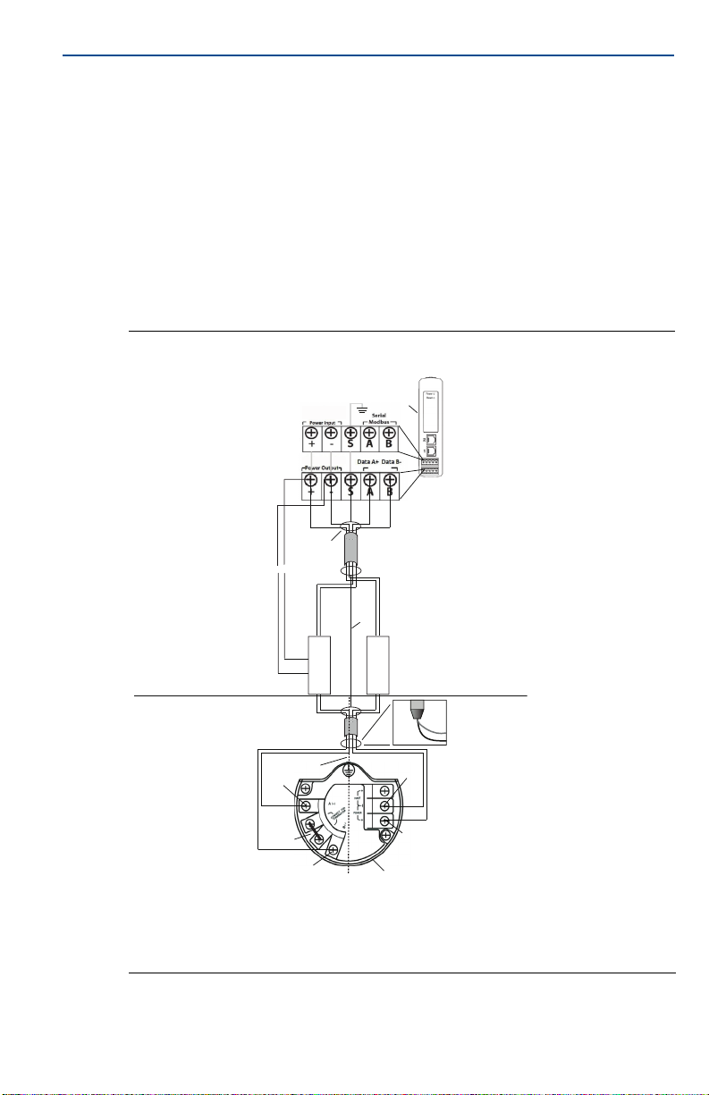
Installation with barriers
When installing the Emerson 781 in a hazardous area there are two I.S. barriers
that need to be installed: a power barrier and a signal barrier. The signal and the
power are two separate I.S. circuits so they must comply with proper I.S.
segregation distance. When using the Emerson recommended barriers the
input power of the Gateway should be 20–30 VDC, with current capacity of at
least 330 mA.
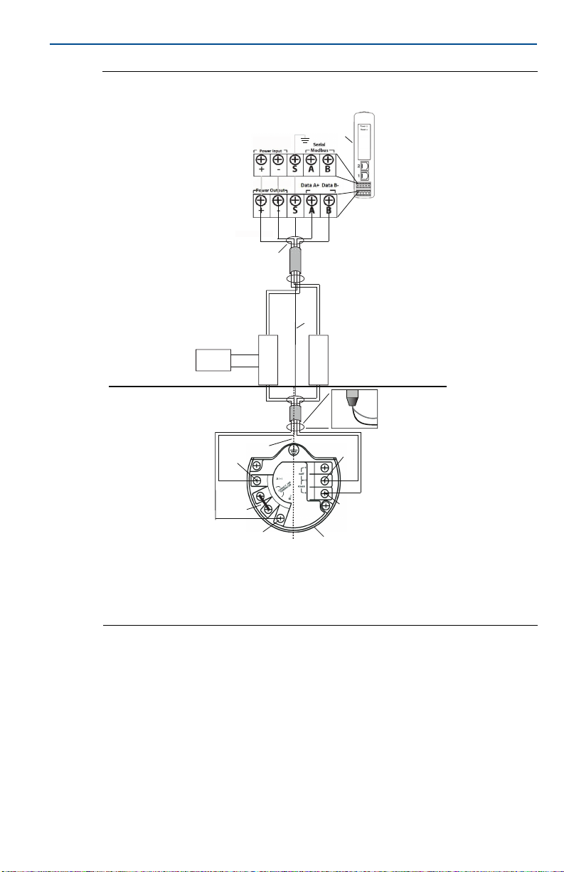
The signal barrier needs additional power. You can wire it to the Emerson 1410D
terminals or to a separate power supply. Make sure power supply is rated to
handle power drawn for the barrier. Figure 10 and Figure 11 show the two
variations of powering the signal barrier.
Figure 10. Emerson 1410D and 781 with Gateway Powered Barrier
February 2019
Installation
14
A. Emerson Wireless 1410D Gateway
B. Attach shield pair cable (Belden 3084A)
C. Tape back shield wire and foils
D. Short these terminals for 250 Ω
E. Emerson Wireless 781 Field Link
F. I.S. segregation
G. Shield
Page 15
February 2019
Figure 11. Emerson 1410D and 781 with Additional Power Supplied Barrier
Quick Start Guide
Installation
Gray line means internal
20-30 VDC
Safe Area
Hazardous Area
connection
Power
Supply
Blu
Wht
Data A (+)
+
-
D
20-30 VDC
Red
Wht
Data+ Data -
F
Data B (-)
Blk
Signal
Data+Data -
B
Blu
Barrier
A
Blu
Wht
Red Blk
G
+
-
Power
Barrier
- +
C
Red
Blk
Return (-)
24 VDC (+)
E
A . E m e r s o n W i r e l e s s 1 4 1 0 D G a t e w a y
B. Attach shield pair cable (Belden 3084A)
C. Tape back shield wire and foils
D. Short these terminals for 250 Ω
Recommendation
Signal barrier
GM-International D1016S
Power barrier
Stahl 9176 10-16-00
E. Emerson Wireless 781 Field Link
F. I .S . segregation
G. Shield
15
Page 16
Quick Start Guide
(May be polymer with
grounding plate)
2
1
A
A
B
D
Shield grounding
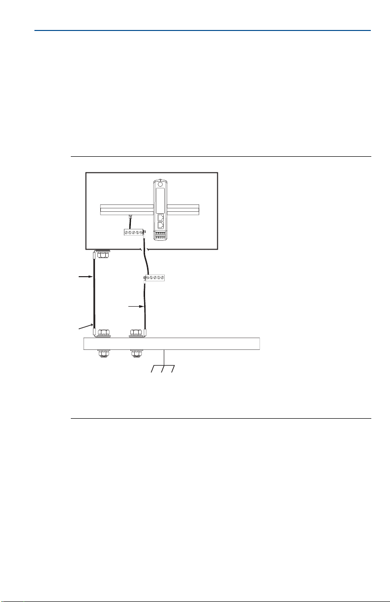
The shield of the twisted pair cable needs to be grounded using the grounding
terminal on the Emerson 1410D, and it should be taped back on the Emerson
781 side.
Emerson 1410D Grounding
The Emerson 1410D DIN rail cabinet must be grounded as well. A #6 AWG
(4.11 mm European) copper wire bonding connector with the shortest length
possible, no sharp bends, and no coiling is recommended.
Figure 12. Emerson 1410D Grounding
February 2019
16
A. #6 AWG copper wire
B. Protective ground
C. Reference ground (when present)
D. Earth
Page 17
February 2019
A
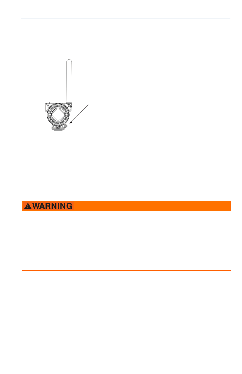
Emerson 781 grounding
Grounding of the electronics enclosure should be done in accordance with local
and national installation codes. Grounding is accomplished through the external
case grounding terminal.
A. Grounding lug
Terminating resistances
For best performance, the terminating resistances should be matched across
the Emerson 1410D, 781, and the signal barrier. The Emerson 1410D has an
integral 250 Ω terminating resistor. Short the Emerson 781 terminator
terminals to engage a 250 Ω resistor (note D of Figure 10 and Figure 11). The
recommended barriers can also be switched to 250 Ω.
Quick Start Guide
4.3 Connecting the Emerson 1410A/B with the remote antenna
When installing remote mount antennas for the Gateway, always use established safety procedures to avoid
falling or contact with high-power electrical lines.
Install remote antenna components for the Gateway in compliance with local and national electrical codes and
use best practices for lightning protection.
Before installing, consult with the local area electrical inspector, electrical officer, and work area supervisor.
The Gateway remote antenna option is specifically engineered to provide installation flexibility while optimizing
wireless performance and local spectrum approvals. To maintain wireless performance and avoid
non-compliance with spectrum regulations, do not change the length of cable or the antenna type.
If the supplied remote mount antenna kit is not installed per these instructions, Emerson is not responsible for
wireless performance or non-compliance with spectrum regulations.
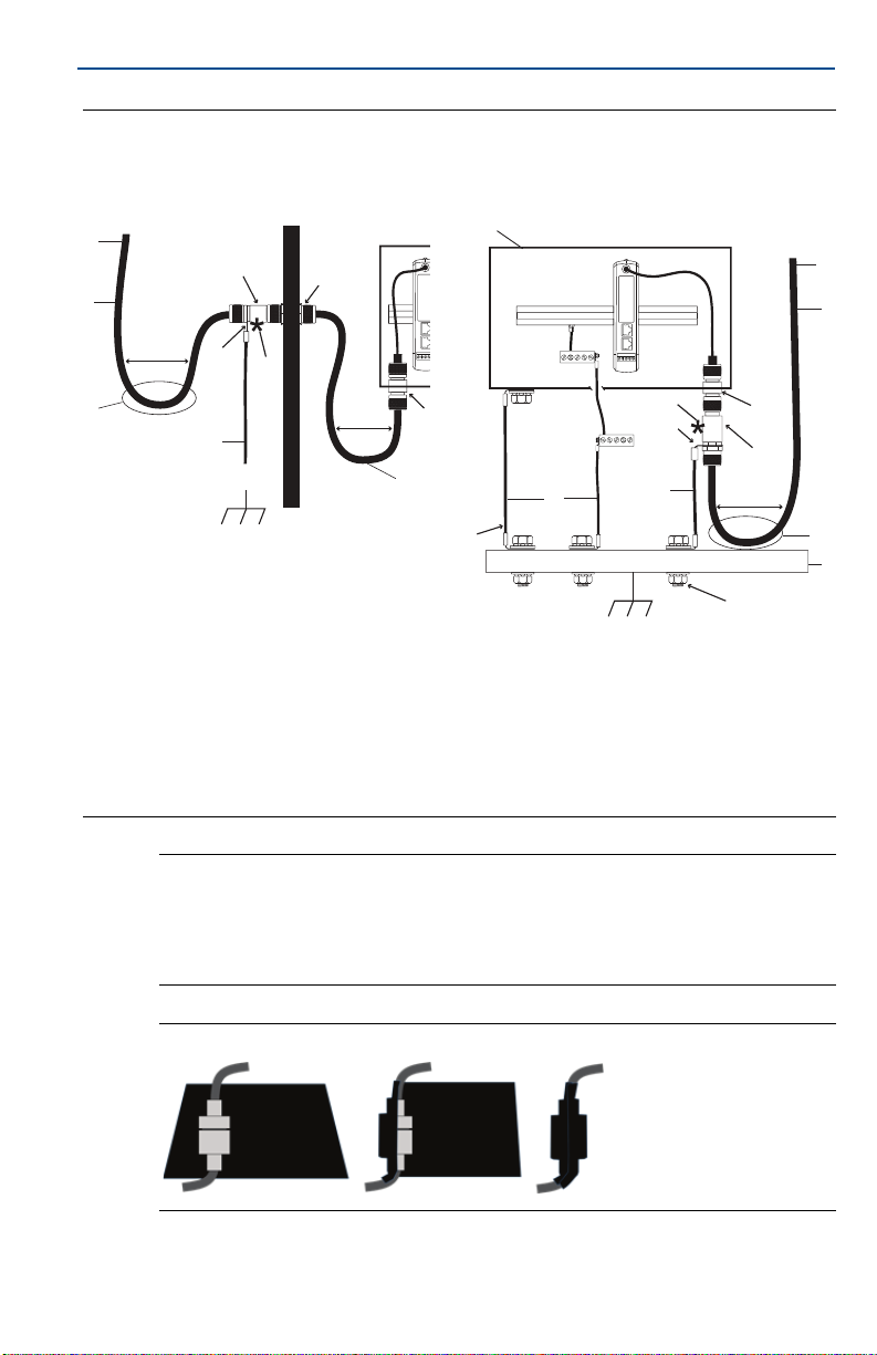
Use only Emerson provided remote antenna, coaxial RF cable, and lightning
arrestor. The remote antenna lightning arrestor must be installed and grounded
in accordance with Figure 13.
Locate the remote antenna to achieve optimal wireless performance. Ideally this
will be 15–25 ft. (4.6–7.6 m) above the ground or 6 ft. (2 m) above obstructions
or major infrastructure. To install the remote antenna, use one of the following
procedures:
17
Page 18

Quick Start Guide
Installation of WL2/WN2 option
1. Mount the antenna on a 11/2- to 2-in. pipe mast using the supplied mounting
equipment.
2. Connect the lightning arrestor either to the electrical cabinet or directly
outside the wall or right outside the wall (depending on where the Gateway is
located).
3. Install the grounding lug, lock washer, and nut on top of the lightning
arrestor.
4. Bond the grounding terminal of the lightning arrestor to a common earth
point using individual high integrity, low resistance means as shown in
Figure 13.
5. The DIN rail cabinet must be grounded as well. A #6 AWG (or 4.11 mm
European) copper wire bonding conductor with the shortest length possible,
no sharp bends, and no coiling is recommended.
6. All the outdoor connections should be made hand tight plus an 1/8th turn with
a wrench and wrapped with the coaxial seal (shown in Figure 14).
7. Ensure the mounting mast, lightning arrestor, and Gateway are grounded
according to local/national electrical code.
Any spare lengths of coaxial cable should be placed in 1 ft. (0.3 m) coils.
February 2019
18
Page 19
February 2019
InsideOutside
2
1
300 mm (11.8-in.)
minimum bend radius
300 mm (11.8-in.)
minimum bend radius
Reference
ground
(when present)
(May be polymer with
grounding plate)
300 mm (11.8-in.)
minimum bend radius
2
1
A
A
B
B
B
C
C
D
D
E
E
E
F
F
G
H
H
G
G
J
I
K
L
L
Figure 13. Installation of WL2/WN2 Option
Indoor/outdoor cabinet and antenna Outdoor cabinet and antenna
Quick Start Guide
A. To antenna
B. Coaxial RF
C. Drip loop
D. Lightning arrestor
E. Type N bulkhead connector
5
F.
/8-in. ring terminal
Note: Weather proofing is required
The remote mount antenna kit includes coaxial sealant for the cable connections for the
lightning arrestor, antenna, and Gateway. The coaxial sealant must be applied to
guarantee performance of the wireless field network. See Figure 14 for details on how to
apply weather proofing.
Figure 14. Applying Coaxial Sealant to Cable Connections
G. #6 AWG copper wire
H. Transient protection ground
I. Outdoor rated enclosure
J. Protective ground
K. Earth
L. Seal per Figure 13
19
Page 20
Quick Start Guide
February 2019
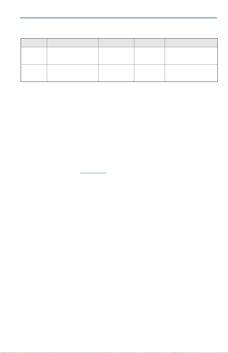
Table 2. Remote Antenna Kit Options
Kit option Antenna Cable 1 Cable 2 Lightning arrestor
1
WL2
WN2
/2 Wavelen gth Dip ole
Omni-Directional
+6 dB Gain
1
/2 Wavelen gth Dip ole
Omni-Directional
+8 dB Gain
50 ft. (15,2 m)
LMR-400
25 ft. (7,6 m)
LMR-400
N/A
N/A
Head mount, jack to plug
Gas discharge tube
0.5 dB insertion loss
Head mount, jack to plug
Gas discharge tube
0.5 dB insertion loss
4.4 Connect to the host system
1. Wire the Gateway’s Ethernet 1 (Primary) or Serial Output connection to the
Host System Network or Serial I/O (see Figure 1 and Figure 2 for hardware
drawings).
2. For serial connections, make sure all terminations are clean and secure to
avoid wiring connection problems.
4.5 Best practice
Twisted shielded pair cable is generally used to wire the serial connection, and it
is standard practice to ground the shield on the serial host side leaving the shield
floating on the Gateway side. Insulate the shield to avoid grounding issues.
®
In accordance with Emerson WirelessHART
Wireless Security Whitepaper), the Gateway should be connected to the Host
System via a LAN (Local Area Network) and not a WAN (Wide Area Network).
security guidelines (Emerson
5.0 Software installation (optional)
The 2-disk software pack contains the Security Setup Utility (only required for
secure host connections or OPC communications) and AMS Wireless
Configurator. The Security Setup Utility is located on Disk 1. To install the
software:
1. Exit/close all Windows programs, including any running in the background,
such as virus scan software.
2. Insert Disk 1 into the CD/DVD drive of the PC.
3. If the setup program does not appear, go into the disc's file and run
autorun.exe.
4. Follow the prompts.
20
Page 21
February 2019
AMS Wireless Configurator is located on Disk 2. To install the software:
1. Exit/close all Windows programs, including any running in the background,
such as virus scan software.
2. Insert Disk 2 into the CD/DVD drive of the PC.
3. Select Install from the menu when the AMS Wireless Configurator setup
begins.
4. Follow the prompts.
5. Allow AMS Wireless Configurator to reboot PC.
6. Do not remove the disk from the CD/DVD drive.
7. Installation will resume automatically after login.
8. Follow the prompts.
Note
If the autorun function is disabled on the PC, or installation does not begin automatically,
double click D:\SETUP.EXE (where D is the CD/DVD drive on the PC) and select OK.
For more information about the Security Setup Utility and AMS Wireless
Configurator, see the Emerson Wireless Gateway 1410 Reference Manual.
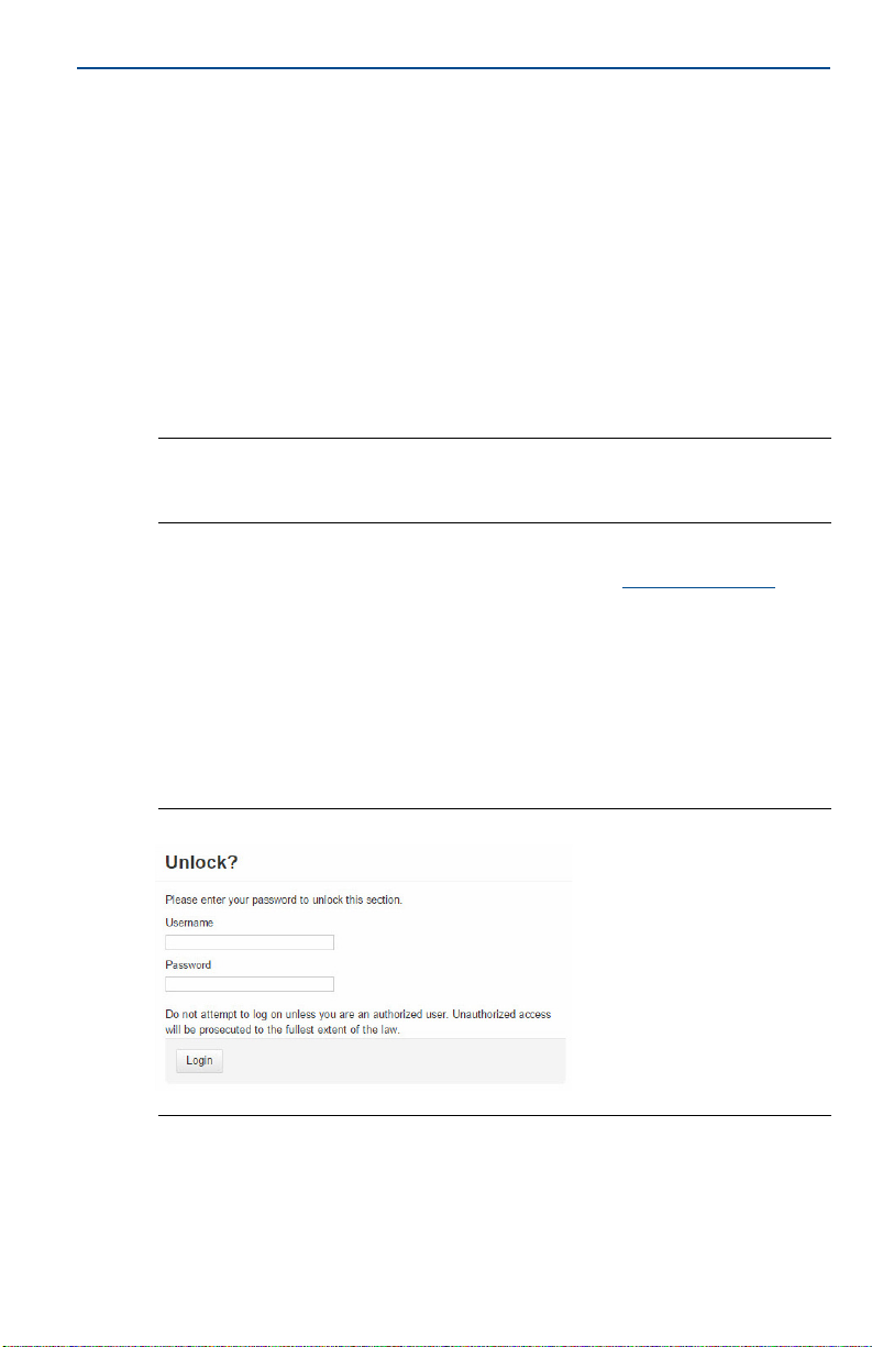
6.0 Verify operations
Operation is verified through the web interface by opening a web browser from
any PC on the host system network and entering the Gateway IP address or
DHCP host name in the address bar. If the Gateway has been connected and
configured properly, the security alert will be displayed followed by the log in
screen.
Quick Start Guide
Figure 15. Gateway Log In Screen
21
Page 22

Quick Start Guide
The Gateway is now ready to be integrated into the host system. If wireless field
devices were ordered with the Gateway, they were preconfigured with the same
Network ID and Join Key information. Once the field devices are powered, they
will appear on the wireless network and communications can be verified under
the Explore tab using the web interface. The time needed for the network to
form will depend on the number of devices.
For more detailed installation instructions, see the Emerson Wireless Gateway
1410 Reference Manual
February 2019
.
22
Page 23

February 2019
7.0 Product Certification
Rev 2.0
7.1 European Directive Information
A copy of the EC Declaration of Conformity can be found at the end of the Quick
Start Guide. The most recent revision of the EC Declaration of Conformity can be
found at Emerson.com/Rosemount
7.2 Telecommunication Compliance
All wireless devices require certification to ensure they adhere to regulations
regarding the use of the RF spectrum. Nearly every country requires this type of
product certification. Emerson is working with governmental agencies around
the world to supply fully compliant products and remove the risk of violating
country directives or laws governing wireless device usage.
7.3 FCC and IC
This device complies with Part 15 of the FCC Rules. Operation is subject to the
following conditions: This device may not cause harmful interference. This
device must accept any interference received, including interference that may
cause undesired operation. This device must be installed to ensure a minimum
antenna separation distance of 20 cm from all persons.
7.4 Ordinary Location Certification
As standard, the transmitter has been examined and tested to determine that
the design meets the basic electrical, mechanical, and fire protection
requirements by a nationally recognized test laboratory (NRTL) as accredited by
the Federal Occupational Safety and Health Administration (OSHA).
.
Quick Start Guide
North America
N5 U.S.A. Division 2
Certificate: 2646342 (CSA)
Standards: CAN/CSA C22.2 No. 0-10, CSA C22.2 No. 213-M1987 (2013), CSA C22.2 No.
61010-1 - 2012, ANSI/ISA-12.12.01 - 2012, UL61010-1, 3rd Edition
Markings: Suitable for CL I, DIV 2, GP A, B, C, D;
Temperature Code: T4 (-40 °C ≤ T
Note
Shall be powered by a class 2 power supply.
Suitable for dry indoor locations only.
Equipment must be installed in a suitable tool accessible enclosure subject to
the end use application.
Using the Emerson 1410D and the 781 Wireless Field Link in a hazardous
location requires barriers between the two units
1.
≤ 70 °C)
a
23
Page 24
Quick Start Guide
Canada
N6 Canada Division 2
Certificate: 2646342 (CSA)
Standards: CAN/CSA C22.2 No. 0-10, CSA C22.2 No. 213-M1987 (R2013),
Markings: Suitable for CL I, DIV 2, GP A, B, C, D
Tem per atu re code: T4 (– 40 °C ≤ T
Note
Shall be powered by a class 2 power supply.
Suitable for dry indoor locations only.
Equipment must be installed in a suitable tool accessible enclosure subject to the end
use application.
Using the Emerson 1410D and the 781 Wireless Field Link in a hazardous location
requires barriers between the two units.
Europe
N1 ATE X Type n
Certificate: Baseefa14ATEX0125X
Standards: EN 60079-0: 2012, EN 60079-15: 2010
Markings: II 3 G Ex nA IIC T4 Gc, T4(–40 °C ≤ T
Special Conditions for Safe Use (X):
1. The equipment must be installed in an area of not more than Pollution Degree 2 as
defined in IEC 60664-1, and in an enclosure that provides a degree of protection of at
least IP54 and meets the relevant requirements of EN 60079-0 and EN 60079-15.
2. External connections to the equipment must not be inserted or removed unless either
the area in which the equipment is installed is known to be non-hazardous, or the
circuits connected have been de-energized.
3. The equipment is not capable of withstanding the 500 V electrical strength test as
defined in clause 6.5.1 of EN 60079-15: 2010. This must be taken into account during
installation.
4. When fitted, the surface resistivity of the remote antenna is greater than 1 GΩ. To
avoid electrostatic charge build up, it must not be rubbed with a dry cloth or cleaned
with solvents.
CSA C22.2 No. 61010-1 - 2012, ANSI/ISA-12.12.01 - 2012,
UL61010-1, 3rd Edition
≤ 70 °C)
a
≤ +75 °C), V
a
MAX
= 30 Vdc
February 2019
N7 IECEx Type n
24
Note
Currently not available for Emerson 1410D option.
International
Certificate: IECEx BAS 14.0067X
Standards: IEC 60079-0: 2011, IEC 60079-15: 2010
Markings: Ex nA IIC T4 Gc, T4(-40 °C ≤ T
≤ +75 °C), V
a
MAX
= 30 Vdc
Page 25

February 2019
Special Conditions for Safe Use (X):
1. The equipment must be installed in an area of not more than Pollution Degree 2 as
defined in IEC 60664-1, and in an enclosure that provides a degree of protection of at
least IP54 and meets the relevant requirements of EN 60079-0 and EN 60079-15.
2. External connections to the equipment must not be inserted or removed unless either
the area in which the equipment is installed is known to be nonhazardous, or the
circuits connected have been de-energized.
3. The equipment is not capable of withstanding the 500 V electrical strength test as
defined in clause 6.5.1 of EN 60059-15: 2010. This must be taken into account during
installation.
4. When fitted, the surface resistivity of the remote antenna is greater than 1 GW. To
avoid electrostatic charge build-up, it must not be rubbed with a dry cloth or cleaned
with solvents.
Note
Currently not available for Emerson 1410D option.
EAC - Belarus, Kazakhstan, Russia
NM Technical Regulation Customs Union (EAC) Type n
Certificate: TC RU C-US.Gb05.B.01111
Markings: 2Ex nA IIC T4 Gc X, T4(–40 °C ≤ T
Special Condition for Safe Use (X):
1. See certificate for special conditions.
≤ +75 °C), V
a
MAX
Quick Start Guide
= 30 Vdc
Note
Currently not available for Emerson 1410D option.
25
Page 26
Quick Start Guide
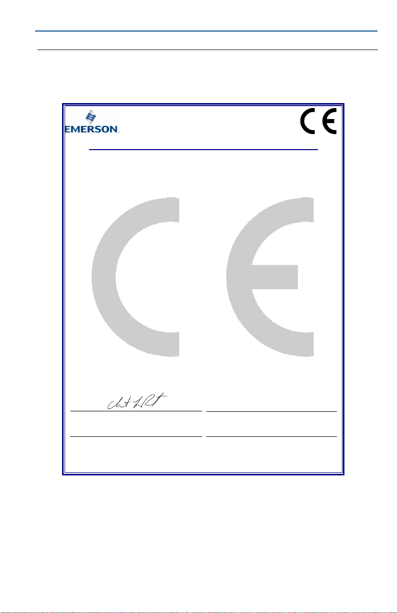
EU Declaration of Conformity
No: RMD 1093 Rev. G
Page 1 of 3
We,
Rosemount, Inc.
8200 Market Boulevard
Chanhassen, MN 55317-9685
USA
declare under our sole responsibility that the product,
Rosemount 1410 Wireless Gateway
manufactured by,
Rosemount, Inc.
8200 Market Boulevard
Chanhassen, MN 55317-9685
USA
to which this declaration relates, is in conformity with the provisions of the European Union
Directives, including the latest amendments, as shown in the attached schedule.
Assumption of conformity is based on the application of the harmonized standards and, when
applicable or required, a European Union notified body certification, as shown in the attached
schedule.
Vice President of Global Quality
Chris LaPoint
1-Feb-19
Figure 16. Emerson 1410 Wireless Gateway Declaration of Conformity
(signature)
(name)
(function)
(date of issue)
February 2019
26
Page 27

February 2019
EU Declaration of Conformity
No: RMD 1093 Rev. G
EMC Directive (2014/30/EU)
Harmonized Standards:
EN 61326-1: 2013
Radio Equipment Directive (RED) (2014/53/EU)
Harmonized Standards:
EN 300 328 V2.1.1
EN 301 489-17: V3.2.0
EN 60950-1: 2006+A11+A12+A1+A2
EN 50371: 2002
ATEX Directive (2014/34/EU)
Baseefa14ATEX0125X – Type n Certificate
Equipment Group II, Category 3 G
Ex nA IIC T4 Gc
Harmonized Standards:
EN 60079-0: 2012 + A11:2013
EN 60079-15: 2010
Quick Start Guide
Page 2 of 3
27
Page 28
Quick Start Guide
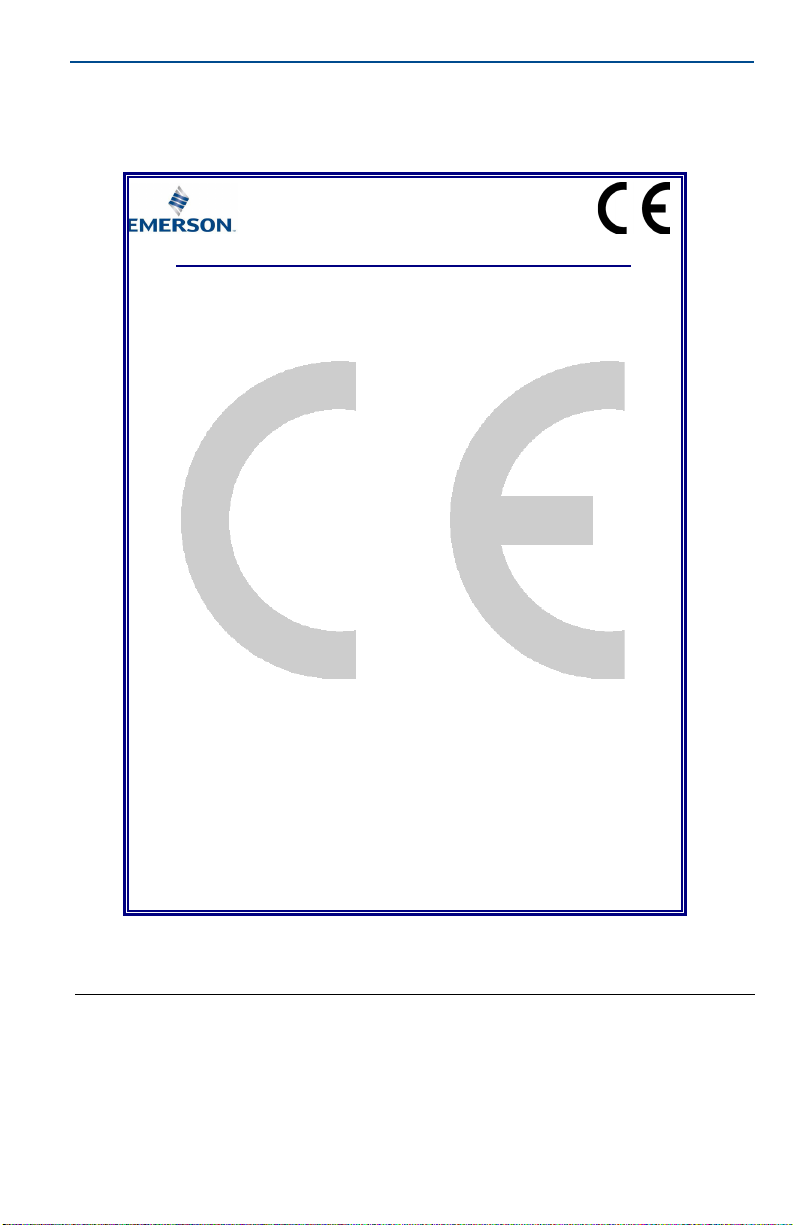
EU Declaration of Conformity
No: RMD 1093 Rev. G
Page 3 of 3
ATEX Notified Body
SGS FIMKO OY [Notified Body Number: 0598]
P.O. Box 30 (Särkiniementie 3)
00211 HELSINKI
Finland
ATEX Notified Body for Quality Assurance
SGS FIMKO OY [Notified Body Number: 0598]
P.O. Box 30 (Särkiniementie 3)
00211 HELSINKI
Finland
February 2019
28
Page 29
February 2019
ᴹ
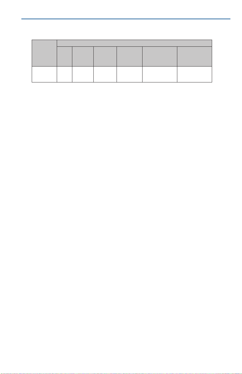
China RoHS
㇑᧗⢙䍘䎵䗷ᴰབྷ⎃ᓖ䲀٬Ⲵ䜘Ԧරࡇ㺘
List of Parts with China RoHS Concentration above MCVs
䜘Ԧ〠
Part Name
ᴹᇣ⢙䍘䍘/ Hazardous Substances
䫵
Lead
(Pb)
⊎
Mercury
(Hg)
䭹
Cadmium
(Cd)
ޝԧ䬜䬜
Hexavalent
Chromium
(Cr +6)
ཊⓤ㚄㚄㤟
Polybrominated
biphenyls
(PBB)
ཊⓤ㚄㚄㤟䟊
Polybrominated
diphenyl ethers
(PBDE)
⭥ᆀ㓴Ԧ
Electronics
Assembly
X O O O O
O
ᵜ㺘Ṭ㌫ᦞ
SJ/T11364
Ⲵ㿴ᇊ㘼ࡦ
This table is proposed in accordance with the provision of SJ/T11364.
O:
Ѫ䈕䜘ԦⲴᡰᴹ൷䍘ᶀᯉѝ䈕ᴹᇣ⢙䍘Ⲵ䟿൷վҾ
GB/T 26572
ᡰ㿴ᇊⲴ䲀䟿㾱≲
O: Indicate that said hazardous substance in all of the homogeneous materials for this part is below the limit requirement of
GB/T 26572.
X:
Ѫ൘䈕䜘Ԧᡰ֯⭘Ⲵᡰᴹ൷䍘ᶀᯉ䟼ˈ㠣ቁᴹа㊫൷䍘ᶀᯉѝ䈕ᴹᇣ⢙䍘Ⲵ䟿儈Ҿ
GB/T 26572
ᡰ㿴ᇊⲴ䲀䟿㾱≲
X: Indicate that said hazardous substance contained in at least one of the homogen eous materials used for this pa rt is above
the limit requirement of GB/T 26572.
Rosemount 1410
Rosemount 1410
Quick Start Guide
29
Page 30
Global Headquarters
Emerson Automation Solutions
6021 Innovation Blvd.
Shakopee, MN 55379, USA
+1 800 999 9307 or +1 952 906 8888
+1 952 949 7001
[email protected]
North America Regional Office
Emerson Automation Solutions
8200 Market Blvd.
Chanhassen, MN 55317, USA
+1 800 999 9307 or +1 952 906 8888
+1 952 949 7001
[email protected]
Latin America Regional Office
Emerson Automation Solutions
1300 Concord Terrace, Suite 400
Sunrise, FL 33323, USA
+1 954 846 5030
+1 954 846 5121
[email protected]
Europe Regional Office
Emerson Automation Solutions
Neuhofstrasse 19a P.O. Box 1046
CH 6340 Baar
Switzerland
+41 (0) 41 768 6111
+41 (0) 41 768 6300
[email protected]
Asia Pacific Regional Office
Emerson Automation Solutions
1 Pandan Crescent
Singapore 128461
+65 6777 8211
+65 6777 0947
[email protected]
Middle East and Africa Regional Office
Emerson Automation Solutions
Emerson FZE P.O. Box 17033
Jebel Ali Free Zone - South 2
Dubai, United Arab Emi rates
+971 4 8118100
+971 4 8865465
*00825-0200-4410*
Quick Start Guide
00825-0200-4410, Rev EC
Linkedin.com/company/Emerson-Automation-Solutions
Twitter.com/Rosemount_News
Facebook.com/Rosemount
Youtube.com/us er/RosemountMeasur ement
Google.com/+RosemountMeasurement
Emerson Terms and Conditions of Sale are available upon re quest.
The Emerson logo is a trademark and service mark of Emerson
Electric Co.
Rosemount is a mark of one of the Emerson family of companies.
All other marks are the property of their respective owners.
© 2019 Emerson. All rights reserved.
February 2019
 Loading...