


Reference Manual
00809-0400-4004, Rev AB
October 2021
Rosemount™ 8800D Series Vortex Flow Meter
with Modbus Protocol

2

Reference Manual Contents
00809-0400-4004 October 2021
Contents
Rosemount™ 8800D Vortex Flowmeter................................................................................. 0
Chapter 1 Safety messages.........................................................................................................7
Chapter 2 Introduction.............................................................................................................. 9
2.1 Overview..................................................................................................................................... 9
Chapter 3 Pre-installation........................................................................................................ 11
3.1 Planning.................................................................................................................................... 11
3.2 Commissioning..........................................................................................................................15
Chapter 4 Basic installation...................................................................................................... 17
4.1 Handling....................................................................................................................................17
4.2 Flow direction............................................................................................................................17
4.3 Gaskets......................................................................................................................................17
4.4 Insulation...................................................................................................................................18
4.5 Flanged-style flow meter mounting...........................................................................................18
4.6 Wafer-style flow meter alignment and mounting...................................................................... 20
4.7 Cable glands.............................................................................................................................. 22
4.8 Flow meter grounding............................................................................................................... 22
4.9 Grounding the transmitter case.................................................................................................23
4.10 Conduit installation................................................................................................................. 24
4.11 Wiring......................................................................................................................................24
4.12 Remote installation................................................................................................................. 25
4.13 Quad transmitter numbering and orientation..........................................................................30
Chapter 5 Basic configuration.................................................................................................. 33
5.1 About basic configuration..........................................................................................................33
5.2 Connect configuration tool ....................................................................................................... 33
5.3 Process variables........................................................................................................................34
5.4 Process configuration................................................................................................................ 36
5.5 Reference K-factor.....................................................................................................................37
5.6 Flange type................................................................................................................................38
5.7 Pipe I.D...................................................................................................................................... 38
5.8 Optimize Digital Signal Processing (DSP)................................................................................... 39
5.9 Modbus communication settings.............................................................................................. 39
Chapter 6 Advanced installation...............................................................................................43
6.1 Insert integral temperature sensor.............................................................................................43
6.2 Pulse output.............................................................................................................................. 44
6.3 Transient protection.................................................................................................................. 45
Chapter 7 Advanced configuration...........................................................................................47
Reference Manual 3

Contents Reference Manual
October 2021 00809-0400-4004
7.1 LCD display................................................................................................................................ 47
7.2 Compensated K-factor...............................................................................................................47
7.3 Meter body................................................................................................................................48
7.4 Meter factor...............................................................................................................................48
7.5 Variable mapping...................................................................................................................... 48
7.6 Pulse output.............................................................................................................................. 49
7.7 Signal processing.......................................................................................................................50
7.8 Special process variable units.....................................................................................................53
7.9 Flow totalizer.............................................................................................................................54
Chapter 8 Troubleshooting...................................................................................................... 57
8.1 Communication problem with HART-based communicator.......................................................57
8.2 Incorrect Modbus communication output................................................................................. 57
8.3 Modbus communication setting fails to apply............................................................................57
8.4 Incorrect pulse output............................................................................................................... 58
8.5 Error messages on a HART-based communicator.......................................................................58
8.6 Flow in Pipe, No Output............................................................................................................. 58
8.7 No flow, output......................................................................................................................... 59
8.8 Diagnostic messages................................................................................................................. 60
8.9 Electronics test points................................................................................................................63
Chapter 9 Maintenance............................................................................................................67
9.1 Transient protection.................................................................................................................. 67
9.2 Installing the LCD indicator........................................................................................................68
9.3 Hardware replacement.............................................................................................................. 70
9.4 Return of material......................................................................................................................84
Appendix A Product Specifications..............................................................................................87
A.1 Physical specifications............................................................................................................... 87
A.2 Performance specifications........................................................................................................91
A.3 Typical flow rates.......................................................................................................................96
A.4 HART specifications.................................................................................................................104
A.5 Modbus RS-485 specifications................................................................................................. 108
A.6 LCD indicator functional specifications.................................................................................... 108
A.7 Quality certificate details.........................................................................................................110
Appendix B Spacers.................................................................................................................. 113
Appendix C Electronics verification........................................................................................... 115
C.1 Electronics verification using flow simulation mode.................................................................115
C.2 Fixed flow rate simulation........................................................................................................116
C.3 Varying flow rate simulation....................................................................................................116
C.4 Verify electronics using an external frequency generator.........................................................116
C.5 Output variable calculations with known input frequency........................................................118
C.6 Unit conversion table...............................................................................................................119
4 Rosemount™ 8800D Series Vortex Flow Meter with Modbus Protocol

Reference Manual Contents
00809-0400-4004 October 2021
C.7 Example calculations............................................................................................................... 119
Appendix D Modbus details.......................................................................................................125
D.1 Byte transmission order...........................................................................................................125
D.2 Input registers (Modbus function code 4)................................................................................125
D.3 Holding registers (Modbus function code 3)............................................................................128
Reference Manual 5

Contents Reference Manual
October 2021 00809-0400-4004
6 Rosemount™ 8800D Series Vortex Flow Meter with Modbus Protocol

Reference Manual Safety messages
00809-0400-4004 October 2021
1 Safety messages
WARNING
Explosion hazards. Failure to follow these instructions could cause an explosion,
resulting in death or serious injury.
• Verify the operating atmosphere of the transmitter is consistent with the
appropriate hazardous locations certifications.
• Installation of this transmitter in an explosive environment must be in accordance
with the appropriate local, national, and international standards, codes, and
practices. Review the approvals documents for any restrictions associated with a safe
installation.
• Do not remove transmitter covers or thermocouple (if equipped) in explosive
atmospheres when the circuit is live. Both transmitter covers must be fully engaged
to meet explosion-proof requirements.
• Before connecting a hand-held communicator in an explosive atmosphere, make
sure the instruments in the loop are installed in accordance with intrinsically safe or
non-incendive field wiring practices.
WARNING
Electrical shock hazard. Failure to follow this instruction could result in death or serious
injury. Avoid contact with the leads and terminals. High voltage that may be present on
leads can cause electrical shock.
WARNING
General hazard. Failure to follow these instructions could result in death or serious
injury.
• This product is intended to be used as a flowmeter for liquid, gas, or steam
applications. Do not use for any other purpose.
• Make sure only qualified personnel perform the installation.
Reference Manual 7

Safety messages Reference Manual
October 2021 00809-0400-4004
8 Rosemount™ 8800D Series Vortex Flow Meter with Modbus Protocol

Reference Manual Introduction
00809-0400-4004 October 2021
2 Introduction
2.1 Overview
System description
The Vortex Flow Meter consists of a meter body and transmitter, and measures volumetric
flow rate by detecting the vortices created by a fluid passing by the shedder bar.
The meter body is installed in-line with process piping. A sensor is located at the end of the
shedder bar which creates a sine wave signal due to the passing vortices. The transmitter
measures the frequency of the sine wave and converts it into a flow rate.
Safety messages
Procedures and instructions in this manual may require special precautions to ensure the
safety of the personnel performing the operations. Refer to the safety messages listed at
the beginning of this document, before performing any operations.
Chapters
Section Who uses Description
Pre-installation Planners and
installers
Basic installation Planners and
installers
Basic
configuration
Advanced
installation
Advanced
configuration
Operation Operations
Troubleshooting Installers and
Maintenance Operations
Operations
technicians
Installers Installation procedures required after initial setup for
Operations
technicians
technicians
operations
technicians
technicians
Reference information to help you verify compatibility
between the meter and its application and installation
location
Mechanical and electrical installation instructions typically
required as initial setup in all applications
Configuration parameters typically required as initial setup
in all applications
some applications
Configuration procedures required after initial setup for
some applications
Information on advanced configuration parameters and
functions that can aid in maintaining the flow meter
Troubleshooting techniques, diagnostic information, and
transmitter verification procedures
Information on maintaining the flow meter
Appendixes
Appendixes include supplementary information that may be useful in some situations.
Reference Manual 9

Introduction Reference Manual
October 2021 00809-0400-4004
10 Rosemount™ 8800D Series Vortex Flow Meter with Modbus Protocol

Reference Manual Pre-installation
00809-0400-4004 October 2021
3 Pre-installation
3.1 Planning
3.1.1 Sizing
To determine the correct meter size for optimal flow meter performance:
• Determine the limits of measuring flow.
• Determine the process conditions so that they are within the stated requirements for
Reynolds number and velocity.
Sizing calculations are required to select the proper flow meter size. These calculations
provide pressure loss, accuracy, and minimum and maximum flow rate data to guide in
proper selection. Vortex sizing software can be found using the Selection and Sizing tool.
The Selection and Sizing tool can be accessed online or downloaded for offline use using
this link: www.Emerson.com/FlowSizing.
3.1.2
3.1.3
Wetted material selection
Ensure that the process fluid is compatible with the meter body wetted materials when
specifying the Rosemount 8800D. Corrosion will shorten the life of the meter body.
Consult recognized sources of corrosion data or contact technical support for more
information.
Note
If Positive Material Identification (PMI) is required, perform test on a machined surface.
Orientation
The best orientation for the meter depends on the process fluid, environmental factors,
and any other nearby equipment.
Vertical installation
Vertical, upward, installation allows upward process liquid flow and is generally preferred.
Upward flow ensures that the meter body always remains full and that any solids in the
fluid are evenly distributed.
The meter can be mounted in the vertical down position when measuring gas or steam
flows. This type of application is strongly discouraged for liquid flows, although it can be
done with proper piping design.
Reference Manual 11

Pre-installation Reference Manual
October 2021 00809-0400-4004
Figure 3-1: Vertical installation
A B
A. Liquid or gas flow
B. Gas flow
Note
To ensure the meter body remains full, avoid downward vertical liquid flows where back
pressure is inadequate.
Horizontal installation
For horizontal installation, the preferred orientation is to have the electronics installed to
the side of the pipe. In liquid applications, this helps prevent any entrained air or solids
from striking the shedder bar and disrupting the shedding frequency. In gas or steam
applications, this helps prevent any entrained liquid (such as condensate) or solids from
striking the shedder bar and disrupting the shedding frequency.
Figure 3-2: Horizontal installation
B
A
A. Preferred installation—meter body installed with electronics to side of pipe
B. Acceptable installation—meter body installed with electronics above pipe
High-temperature installations
The maximum process temperature for integral electronics is dependent on the ambient
temperature where the meter is installed. The electronics must not exceed 185 °F (85 °C).
Figure 3-3 shows combinations of ambient and process temperatures needed to maintain
a housing temperature of less than 185 °F (85 °C).
12 Rosemount™ 8800D Series Vortex Flow Meter with Modbus Protocol

Reference Manual Pre-installation
00809-0400-4004 October 2021
Figure 3-3: Ambient/Process temperature limits
200 (93)
180(82)
160 (71)
600 (316)
700 (371)
C
800 (427)
900 (482)
1000 (538)
A
140 (60)
120 (49)
100 (38)
80 (27)
60 (16)
0
100 (38)
200 (93)
300 (149)
400 (204)
500 (260)
B
A. Ambient temperature °F (°C)
B. Process temperature °F (°C)
C. 185 °F (85 °C) Housing temperature limit.
Note
The indicated limits are for horizontal pipe and vertical meter position, with meter and
pipe insulated with 3 in. (77 mm) of ceramic fiber insulation.
Install the meter body so the electronics are positioned to the side of the pipe or below the
pipe as shown in Figure 3-4. Insulation may also be required around the pipe to maintain
an electronics temperature below 185 °F (85 °C). See Figure 4-2 for special insulation
considerations.
Figure 3-4: Examples of high-temperature installations
B
A
A. Preferred installation—The meter body installed with the electronics to the side of the
pipe.
B. Acceptable installation—The meter body installed with the electronics below the pipe.
3.1.4
Location
Hazardous area
The transmitter has an explosion-proof housing and circuitry suitable for intrinsically safe
and non-incendive operation. Individual transmitters are clearly marked with a tag
Reference Manual 13
Pre-installation Reference Manual
October 2021 00809-0400-4004
indicating the certifications they carry. For hazardous location installation, including
Explosion-proof, Flameproof,or Intrinsic Safety (I.S.), please consult the Emerson 8800
Approval Document 00825-VA00-0001.
Environmental considerations
Avoid excessive heat and vibration to ensure maximum flow meter life. Typical problem
areas include high-vibration lines with integrally mounted electronics, warm-climate
installations in direct sunlight, and outdoor installations in cold climates.
Although the signal conditioning functions reduce susceptibility to extraneous noise,
some environments are more suitable than others. Avoid placing the flow meter or its
wiring close to devices that produce high intensity electromagnetic and electrostatic
fields. Such devices include electric welding equipment, large electric motors and
transformers, and communication transmitters.
Upstream and downstream piping
The meter may be installed with a minimum of ten diameters (D) of straight pipe length
upstream and five diameters (D) of straight pipe length downstream.
To achieve reference accuracy, straight pipe lengths of 35D upstream and 5D downstream
are required. The value of the K-factor may shift up to 0.5% when the upstream straight
pipe length is between 10D and 35D. For optional K-factor corrections, see Rosemount
™
8800 Vortex Installation Effects Technical Data Sheet.
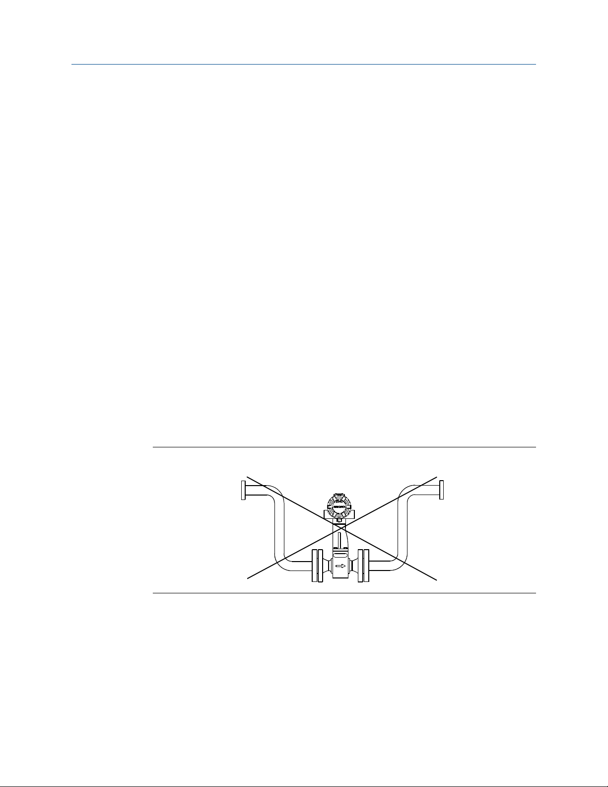
Steam piping
For steam applications, avoid installations such as the one shown in the following figure.
Such installations may cause a water-hammer condition at start-up due to trapped
condensation. The high force from the water hammer can stress the sensing mechanism
and cause permanent damage to the sensor.
Figure 3-5: Wrong steam pipe installation
Pressure and temperature transmitter location
When using pressure and temperature transmitters in conjunction with the vortex flow
meter for compensated mass flows, install the transmitter(s) downstream of the vortex
flow meter.
14 Rosemount™ 8800D Series Vortex Flow Meter with Modbus Protocol

Reference Manual Pre-installation
00809-0400-4004 October 2021
Figure 3-6: Pressure and temperature transmitter location
C
A
B
D
A. Pressure transmitter
B. Four straight pipe diameters downstream
C. Temperature transmitter
D. Six straight pipe diameters downstream
3.1.5
Power supply
The transmitter requires 10 to 30 VDC. The maximum power consumption is 0.4 W.
3.2 Commissioning
For proper configuration and operation, commission the meter before putting it into
operation. Bench commissioning also enables you to check hardware settings, test the
flowmeter electronics, verify flowmeter configuration data, and check output variables.
Any problems can be corrected—or configuration settings changed—before going out into
the installation environment. To commission on the bench, connect a configuration
device to the signal loop in accordance the device instructions.
3.2.1
Alarm and security jumper configuration
Two jumpers on the transmitter specify the alarm and security modes. Set these jumpers
during the commissioning stage to avoid exposing the electronics to the plant
environment. The two jumpers can be found on the electronics board stack or on the LCD
display.
Alarm
Security
The jumper setting for Alarm has no effect when the HART address is set to 1,
which is the required setting for the transmitter when configured for use on a
Modbus network.
You can protect the configuration data with the security lockout jumper. With
the security lockout jumper ON, any configuration changes attempted on the
electronics are disallowed. You can still access and review any of the operating
parameters and scroll through the available parameters, but no changes can
be made. The factory sets the jumper according to the Configuration Data
Sheet, if applicable, or OFF by default.
Reference Manual 15

Pre-installation Reference Manual
October 2021 00809-0400-4004
Note
If you will be changing configuration variables frequently, it may be useful to
leave the security lockout jumper in the OFF position to avoid exposing the
flow meter electronics to the plant environment.
To access the jumpers, remove the transmitter electronics housing or the LCD cover (if
equipped) opposite of the terminal block, See Figure 3-7 and Figure 3-8.
Figure 3-7: Alarm and security jumpers (no LCD option)
VORTEX
4-20mA
HART
TEST FREQ
IN
3.2.2
TP1
Figure 3-8: Alarm and security jumpers (with LCD option)
HI LO
HI LO
ALARM
ALARM
FLOW
SECURITY
SECURITY
ON OFF
ON OFF
Calibration
The flow meter is wet-calibrated at the factory and needs no further calibration during
installation. The calibration factor (K-factor) is indicated on each meter body and is
entered into the electronics. Verification can be accomplished with a configuration device.
16 Rosemount™ 8800D Series Vortex Flow Meter with Modbus Protocol

Reference Manual Basic installation
00809-0400-4004 October 2021
4 Basic installation
4.1 Handling
Handle all parts carefully to prevent damage. Whenever possible, transport the system to
the installation site in the original shipping containers. Keep the shipping plugs in the
conduit connections until you are ready to connect and seal them.
NOTICE
To avoid damage to the meter, do not lift the flow meter by the transmitter. Lift the meter
by the meter body. Lifting supports can be tied around the meter body as shown.
Figure 4-1: Lifting supports
4.2 Flow direction
The meter can only measure flow in the direction indicated on the meter body. Be sure to
mount the meter body so the FORWARD end of the flow arrow points in the direction of
the flow in the pipe.
4.3 Gaskets
The flow meter requires gaskets supplied by the user. Be sure to select gasket material
that is compatible with the process fluid and pressure ratings of the specific installation.
Note
Ensure the inside diameter of the gasket is larger than the inside diameter of the flow
meter and adjacent piping. If gasket material extends into the flow stream, it will disturb
the flow and cause inaccurate measurements.
Reference Manual 17

Basic installation Reference Manual
October 2021 00809-0400-4004
4.4 Insulation
Insulation should extend to the end of the bolt on the bottom of the meter body and
should leave at least 1-in. (25 mm) of clearance around the electronics bracket. The
electronics bracket and electronics housing should not be insulated. See Figure 4-2.
Figure 4-2: Insulation best practice to prevent electronics overheating
A. Support tube
CAUTION
In high temperature installations, to avoid damage to the electronics on integral units or
to the remote cable on remote units, only insulate the meter body as shown. Do not
insulate the support tube. See also Orientation.
4.5 Flanged-style flow meter mounting
Most vortex flow meters use a flanged-style process connection. Physical mounting of a
flanged-style flow meter is similar to installing a typical section of pipe. Conventional
tools, equipment, and accessories (such as bolts and gaskets) are required. Tighten the
nuts following the sequence shown in Figure 4-4.
Note
The required bolt load for sealing the gasket joint is affected by several factors, including
operating pressure and gasket material, width, and condition. A number of factors also
affect the actual bolt load resulting from a measured torque, including condition of bolt
threads, friction between the nut head and the flange, and parallelism of the flanges. Due
to these application-dependent factors, the required torque for each application may be
different. Follow the guidelines outlined in ASME PCC-1 for proper bolt tightening. Make
sure the flow meter is centered between flanges of the same nominal size and rating as
the flow meter.
18 Rosemount™ 8800D Series Vortex Flow Meter with Modbus Protocol

Reference Manual Basic installation
00809-0400-4004 October 2021
Figure 4-3: Flanged-style flow meter installation
A. Installation studs and nuts (supplied by customer)
B. Gaskets (supplied by customer)
C. Flow
Figure 4-4: Flange bolt torquing sequence
Reference Manual 19

Basic installation Reference Manual
October 2021 00809-0400-4004
4.6 Wafer-style flow meter alignment and mounting
Center the wafer-style meter body inside diameter with respect to the inside diameter of
the adjoining upstream and downstream piping. This will ensure the flow meter achieves
its specified accuracy. Alignment rings are provided with each wafer-style meter body for
centering purposes. Follow these steps to align the meter body for installation. Refer to
Figure 4-5.
1. Place the alignment rings over each end of the meter body.
2. Insert the studs for the bottom side of the meter body between the pipe flanges.
3. Place the meter body (with alignment rings) between the flanges.
• Make sure the alignment rings are properly placed onto the studs.
• Align the studs with the markings on the ring that correspond to the flange you
are using.
Note
Be sure to align the flow meter so the electronics are accessible, the conduits drain,
and the flow meter is not subject to direct heat.
4. Place the remaining studs between the pipe flanges.
5. Tighten the nuts in the sequence shown in Figure 4-4.
6. Check for leaks at the flanges after tightening the flange bolts.
Note
The required bolt load for sealing the gasket joint is affected by several factors,
including operating pressure and gasket material, width, and condition. A number
of factors also affect the actual bolt load resulting from a measured torque,
including condition of bolt threads, friction between the nut head and the flange,
and parallelism of the flanges. Due to these application-dependent factors, the
required torque for each application may be different. Follow the guidelines
outlined in ASME PCC-1 for proper bolt tightening. Make sure the flow meter is
centered between flanges of the same nominal size and rating as the flow meter.
20 Rosemount™ 8800D Series Vortex Flow Meter with Modbus Protocol

Reference Manual Basic installation
00809-0400-4004 October 2021
Figure 4-5: Wafer-style flow meter installation with alignment rings
B
B
A
4.6.1
C
D
A. Installation studs and nuts (supplied by customer)
B. Alignment rings
C. Spacer (for Rosemount 8800D to maintain Rosemount 8800A dimensions)
D. Flow
Note
See for instructions on retrofitting 8800D to 8800A installations.
Stud bolts for wafer-style flow meters
The following tables list the recommended minimum stud bolt lengths for wafer-style
meter body size and different flange ratings.
Table 4-1: Stud bolt length for wafer-style flow meters with ASME B16.5 flanges
Line size Minimum recommended stud bolt lengths (in inches) for each flange
rating
Class 150 Class 300 Class 600
½-inch 6.00 6.25 6.25
1-inch 6.25 7.00 7.50
1½-inch 7.25 8.50 9.00
2-inch 8.50 8.75 9.50
3-inch 9.00 10.00 10.50
4-inch 9.50 10.75 12.25
6-inch 10.75 11.50 14.00
8-inch 12.75 14.50 16.75
Reference Manual 21

Basic installation Reference Manual
October 2021 00809-0400-4004
Table 4-2: Stud bolt length for wafer-style flow meters with EN 1092 flanges
Line size Minimum recommended stud bolt lengths (in mm) for each flange rating
PN 16 PN 40 PN 63 PN 100
DN 15 160 160 170 170
DN 25 160 160 200 200
DN 40 200 200 230 230
DN 50 220 220 250 270
DN 80 230 230 260 280
DN 100 240 260 290 310
DN 150 270 300 330 350
DN 200 320 360 400 420
Line size Minimum recommended stud bolt lengths (in mm) for each flange
rating
JIS 10k JIS 16k and 20k JIS 40k
15mm 150 155 185
25mm 175 175 190
40mm 195 195 225
50mm 210 215 230
80mm 220 245 265
100mm 235 260 295
150mm 270 290 355
200mm 310 335 410
4.7 Cable glands
If you are using cable glands instead of conduit, follow the cable gland manufacturer’s
instructions for preparation and make the connections in a conventional manner in
accordance with local or plant electrical codes. Be sure to properly seal unused ports to
prevent moisture or other contamination from entering the terminal block compartment
of the electronics housing.
4.8 Flow meter grounding
Grounding is not required in typical vortex applications; however, a proper ground will
eliminate possible noise pickup by the electronics. Grounding straps may be used to
ensure that the meter is grounded to the process piping. If you are using the transient
protection option (T1), grounding straps are required to provide a proper low impedance
ground.
22 Rosemount™ 8800D Series Vortex Flow Meter with Modbus Protocol

Reference Manual Basic installation
00809-0400-4004 October 2021
Note
Properly ground flow meter body and transmitter per the local code.
To use grounding straps, secure one end of the grounding strap to the bolt extending from
the side of the meter body and attach the other end of each grounding strap to a suitable
ground. See Figure 4-6.
Figure 4-6: Grounding connections
A. Internal ground connection
B. External ground assembly
4.9 Grounding the transmitter case
The transmitter case should always be grounded in accordance with national and local
electrical codes. The most effective transmitter case grounding method is direct
connection to earth ground with minimal impedance. Methods for grounding the
transmitter case include:
Internal
Ground
Connection
External
Ground
Assembly
Note
Grounding the transmitter case using the threaded conduit connection may not provide a
sufficient ground. The transient protection terminal block (Option Code T1) does not
provide transient protection unless the transmitter case is properly grounded. For
transient terminal block grounding, see Transient protection. Use the above guidelines to
The Internal Ground Connection screw is inside the FIELD TERMINALS
side of the electronics housing. This screw is identified by a ground
symbol ( ), and is standard on all Rosemount 8800D transmitters.
This assembly is located on the outside of the electronics housing and
is included with the optional transient protection terminal block
(Option Code T1). The External Ground Assembly can also be ordered
with the transmitter (Option Code V5) and is automatically included
with certain hazardous area approvals. See Figure 4-6 for the location
of the external ground assembly.
Reference Manual 23

Basic installation Reference Manual
October 2021 00809-0400-4004
ground the transmitter case. Do not run the transient protection ground wire with signal
wiring as the ground wire may carry excessive electric current if a lightning strike occurs.
4.10 Conduit installation
Prevent condensation in any conduit from flowing into the housing by mounting the
flowmeter at a high point in the conduit run. If the flowmeter is mounted at a low point in
the conduit run, the terminal compartment could fill with fluid.
If the conduit originates above the flowmeter, route conduit below the flowmeter to form
a drip loop before entry. In some cases a drain seal may need to be installed.
Figure 4-7: Proper conduit installation
A A
A. Conduit line
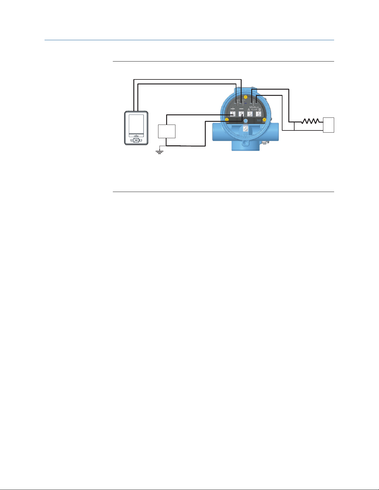
4.11 Wiring
1. Supply 10–30 VDC to the positive (+) and negative (–) terminals. The power
terminals are polarity insensitive: the polarity of the DC power leads does not
matter when connecting to the power terminals.
24 Rosemount™ 8800D Series Vortex Flow Meter with Modbus Protocol

Reference Manual Basic installation
00809-0400-4004 October 2021
Figure 4-8: Modbus and power supply wiring
C
A. RS-485 (A)
B. RS-485 (B)
C. 10–30 VDC power supply
2. Connect Modbus RTU communication wires to the Modbus A and B terminals.
Note
Twisted pair wiring is required for RS-485 bus wiring. Wiring runs under 1000 ft
(305 m) should be AWG 22 or larger. Wiring runs from 1000 to 4000 ft. (305 to
1219 m) should be AWG 20 or larger. Wiring should not exceed AWG 16.
4.12 Remote installation
If a remote electronics option (Rxx or Axx) was ordered, the flow meter assembly will be
shipped in two parts:
• The meter body with an adapter installed in the support tube and an interconnecting
coaxial cable attached to it.
B
A
• The electronics housing installed on a mounting bracket.
If an armored remote electronics option (Axx) was ordered, follow the same instructions as
for the standard remote cable connection with the exception that the cable may not need
to be run through conduit. Both standard and armored cable include cable glands.
Information on remote installation can be found in Cable connections.
4.12.1
Reference Manual 25
Mounting
Mount the meter body in the process flow line as described earlier in this section. Mount
the bracket and electronics housing in the desired location. The housing can be
repositioned on the bracket to facilitate field wiring and conduit routing.

Basic installation Reference Manual
October 2021 00809-0400-4004
4.12.2 Cable connections
Complete these steps for connecting the loose end of the coaxial cable to the electronics
housing. If connecting/disconnecting the meter adapter to the meter body,.
Figure 4-9: Remote installation
A
B
C
D
E
F
G
H
P
O
N
J
K
I
M
L
A. ½ NPT conduit adapter or cable gland (supplied by customer for Rxx options)
B. Coaxial cable
C. Meter adapter
D. Union
E. Washer
F. Nut
G. Sensor cable nut
H. Support tube
I. Meter body
J. Electronics housing
K. Coaxial cable SMA nut
L. ½ NPT conduit adapter or cable gland (supplied by customer for Rxx options)
M. Housing adapter screws
N. Housing adapter
O. Housing base screw (one of four)
P. Ground connection
26 Rosemount™ 8800D Series Vortex Flow Meter with Modbus Protocol

Reference Manual Basic installation
00809-0400-4004 October 2021
CAUTION
To prevent moisture from entering the coaxial cable connections, install the
interconnecting coaxial cable in a single dedicated conduit run or use sealed cable
glands at both ends of the cable.
In remote mount configurations when ordered with a hazardous area option code, the
remote sensor cable and the interconnecting thermocouple cable are protected by
separate intrinsic safety circuits, and must be segregated from each other, other
intrinsically safe circuits, and non-intrinsically safe circuits per local and national wiring
code.
CAUTION
The coaxial remote cable cannot be field terminated or cut to length. Coil any extra
coaxial cable with no less than a 2-in. (51 mm) radius.
1. If you plan to run the coaxial cable in conduit, carefully cut the conduit to the
desired length to provide for proper assembly at the housing. A junction box may
be placed in the conduit run to provide a space for extra coaxial cable length.
2. Slide the conduit adapter or cable gland over the loose end of the coaxial cable and
fasten it to the adapter on the meter body support tube. If coaxial remote cable
originates or any part of the cable is above the flow meter, route cable below the
flow meter to form a drip loop before the meter body support tube.
3. If using conduit, route the coaxial cable through the conduit.
4. Place a conduit adapter or cable gland over the end of the coaxial cable.
5. Remove the housing adapter from the electronics housing.
6. Slide the housing adapter over the coaxial cable.
7. Remove one of the four housing base screws.
8. Attach the coaxial cable ground wire to the housing via the housing base ground
screw.
9. Attach and hand tighten the coaxial cable SMA nut to the electronics housing to 7
in-lbs (0.8 N-m).
Reference Manual 27

Basic installation Reference Manual
October 2021 00809-0400-4004
Figure 4-10: Attaching and tightening SMA nut
A
B
A. SMA nut
B. Hand tighten
Note
Do not over-tighten the coaxial cable nut to the electronics housing.
4.12.3
10. Align the housing adapter with the housing and attach with two screws.
11. Tighten the conduit adapter or cable gland to the housing adapter.
Housing rotation
The entire electronics housing may be rotated in 90° increments for easy viewing. Use the
following steps to change the housing orientation,
1. Loosen the housing rotation set screws at the base of the electronics housing with a
5/32” hex wrench by turning the screws clockwise (inward) until they clear the
support tube.
2. Slowly pull the electronics housing out of the support tube.
CAUTION
Do not pull the housing more than 1.5 in. (40 mm) from the top of the support
tube until the sensor cable is disconnected. Damage to the sensor may occur if
this sensor cable is stressed.
3. Unscrew the sensor cable from the housing with a 5/16” open end wrench.
4. Rotate the housing to the desired orientation.
5. Hold it in this orientation while you screw the sensor cable onto the base of the
housing.
CAUTION
Do not rotate the housing while the sensor cable is attached to the base of the
housing. This will stress the cable and may damage the sensor.
6. Place the electronics housing into the top of the support tube.
28 Rosemount™ 8800D Series Vortex Flow Meter with Modbus Protocol

Reference Manual Basic installation
00809-0400-4004 October 2021
7. Use a hex wrench to turn the housing rotation screws counter-clockwise (outward)
to engage the support tube.
4.12.4 Specifications and requirements for remote sensor cable
If using a Rosemount remote sensor cable, observe these specifications and requirements.
• The remote sensor cable is a proprietary design tri-axial cable
• It is considered a low voltage signal cable
• It is rated for and/or part of intrinsically safe installations
• Non armored version is designed to be run through metal conduit
• Cable is water resistant, but not submersible. As a best practice, exposure to moisture
should be avoided if possible
• Rated operating temperature is –58°F to +392°F (–50°C to +200°C)
• Flame Resistant in accordance with IEC 60332-3
• Non-armored and armored version minimum bend diameter is 8 inches (203 mm)
• Nominal O.D. of the non-armored version is 0.160 inches (4 mm)
• Nominal O.D. of the armored version is 0.282 inches (7.1 mm)
Figure 4-11: Non-armored cable
A. Transmitter end
B. Sensor end
C. Minimum bend diameter
D. Nominal O.D.
Reference Manual 29

Basic installation Reference Manual
October 2021 00809-0400-4004
Figure 4-12: Armored cable
A. Transmitter end
B. Sensor end
C. Minimum bend diameter
4.13 Quad transmitter numbering and orientation
When quad vortex flow meters are ordered, for configuration purposes, the transmitters
are identified as Transmitter 1, Transmitter 2, Transmitter 3, and Transmitter 4. The
transmitter and meter body nameplate of a Quad Vortex flow meter can be used to
identify and verify the transmitter number. See Figure 4-13 for Quad transmitter
orientation and nameplate locations. See Figure 4-14 and 4-15 for Quad transmitter and
meter body nameplate number location.
30 Rosemount™ 8800D Series Vortex Flow Meter with Modbus Protocol

Reference Manual Basic installation
00809-0400-4004 October 2021
Figure 4-13: Quad transmitter numbering
A. Transmitter nameplate (Transmitter 1)
B. Meter body nameplate (Transmitter 1)
Reference Manual 31

Basic installation Reference Manual
October 2021 00809-0400-4004
Figure 4-14: Quad transmitter nameplate
Figure 4-15: Quad meter body nameplate
32 Rosemount™ 8800D Series Vortex Flow Meter with Modbus Protocol

Reference Manual Basic configuration
00809-0400-4004 October 2021
5 Basic configuration
5.1 About basic configuration
The transmitter will be configured at the factory before shipment. If further configuration
changes are required, note the following:
• A HART communication tool must be used. Examples are ProLink III Software or AMS
Software with a HART modem, or Emerson AMS Trex Device Communicator or 475
Field Communicator.
• The transmitter leaves the factory at HART address 1. Verify that the HART
communication tool is configured to poll beyond address 0.
Important
Do not change the transmitter HART address; it should always be set to 1.
• The COMM terminals must be used for configuration. A built-in load resistor is provided
for HART communication; an external load resistor is not required.
Note
After measurement configuration and Modbus communication settings are configured
with a HART communicatoin tool, the flow meter can be used to output measurement
data to a Modbus host.
5.2 Connect configuration tool
If configuration changes are needed, connect the configuration tool to the transmitter as
shown in Figure 5-1.
Reference Manual 33

C
B
A
Basic configuration Reference Manual
October 2021 00809-0400-4004
Figure 5-1: HART configuration tool connection to COMM port
A. Example AMS Trex Device Communicator
B. Example ProLink III software on PC
C. 10–30 VDC power supply
Tip
If you do not have an external power supply during configuration, you can temporarily
power the transmitter directly through the COMM terminals using the AMS Trex Device
Communicator.
5.3 Process variables
Process variables define the flow meter output. When commissioning a flow meter, review
each process variable, its function and output, and take corrective action if necessary
before using the flow meter in a process application.
5.3.1
Primary variable mapping
Allows the user to select which variables the transmitter will output.
ProLink III
Flow variables are available as Corrected Volume Flow, Mass Flow, Velocity Flow, Volume
Flow or Process Temperature (MTA option only).
Device Tools → Configuration → Communications (HART)
When bench commissioning, the flow values for each variable should be zero and the
temperature value should be the ambient temperature.
34 Rosemount™ 8800D Series Vortex Flow Meter with Modbus Protocol
If the units for the flow or temperature variables are not correct, refer to Process variable
units. Use the Process Variable Units function to select the units for your application.

Reference Manual Basic configuration
00809-0400-4004 October 2021
5.3.2 Process variable units
ProLink III Device Tools → Configuration → Process Measurement →
(select type)
Allows for the viewing and configuration of Process Variable Units such as Volume,
Velocity, Mass Flow, Electronics Temperature, Process Density, and Corrected Volume
units, including corrected volume Special Units configuration.
Volume flow units
Allows the user to select the volumetric flow units from the available list.
Table 5-1: Volume flow units
gallons per second gallons per minute gallons per hour
gallons per day cubic feet per second cubic feet per minute
cubic feet per hour cubic feet per day barrels per second
barrels per minute barrels per hour barrels per day
imperial gallons per second imperial gallons per minute imperial gallons per hour
imperial gallons per day liters per second liters per minute
liters per hour liters per day cubic meters per second
cubic meters per minute cubic meters per hour cubic meters per day
mega cubic meters per day special units
Corrected volumetric flow units
Allows the user to select the corrected volumetric flow units from the available list.
Table 5-2: Corrected volume flow units
gallons per second gallons per minute gallons per hour
gallons per day cubic feet per second standard cubic feet per minute
standard cubic feet per hour cubic feet per day barrels per second
barrels per minute barrels per hour barrels per day
imperial gallons per second imperial gallons per minute imperial gallons per hour
imperial gallons per day liters per second liters per minute
liters per hour liters per day normal cubic meters per
minute
normal cubic meters per hour normal cubic meters per day cubic meters per second
cubic meters per minute cubic meters per hour cubic meters per day
special units
Reference Manual 35

Basic configuration Reference Manual
October 2021 00809-0400-4004
Note
When measuring corrected volumetric flow, a base density and process density must be
provided. The base density and process density are used to calculate the density ratio
which is a value used to convert actual volume flow to corrected volume flow.
Mass flow units
Allows the user to select the mass flow units from the available list. (1 STon = 2000 lb; 1
MetTon = 1000 kg)
Table 5-3: Mass flow units
grams per hour grams per minute grams per second
kilograms per day kilograms per hour kilograms per minute
kilograms per second pounds per minute pounds per hour
pounds per day special units short tons per day
short tons per hour short tons per minute pounds per second
tons (metric) per day tons (metric) per hour tons (metric) per minute
Note
If you select a Mass Flow Units option, you must enter process density in your
configuration.
Velocity flow units
Allows the user to select the Velocity Flow Units from the available list.
• feet per second
• meters per second
Velocity measurement base
Determines if the velocity measurement is based on the mating pipe ID or the meter body
ID. This is important for Reducer™ Vortex Applications.
5.4 Process configuration
ProLink III Device Tools → Configuration → Device Setup
The flow meter can be used for liquid or gas/steam applications, but it must be configured
specifically for the application. If the flow meter is not configured for the proper process,
readings will be inaccurate. Select the appropriate process configuration parameters for
your application:
Transmitter mode
For units with an integral temperature sensor, the temperature sensor can be activated
here.
• Without Temperature Sensor
• With Temperature Sensor
36 Rosemount™ 8800D Series Vortex Flow Meter with Modbus Protocol

Reference Manual Basic configuration
00809-0400-4004 October 2021
Set process fluid
Select the fluid type—either Liquid, Gas/Steam, Tcomp Sat Steam, or Tcomp Liquids.
Tcomp Sat Steam and Tcomp Liquids require the MTA Option and provide dynamic
density compensation based on the process temperature reading.
Fixed process temperature
Needed for the electronics to compensate for thermal expansion of the flow meter as the
process temperature differs from the reference temperature. Process temperature is the
temperature of the liquid or gas in the line during flow meter operation.
May also be used as a back-up temperature value in the event of a temperature sensor
failure if the MTA option is installed.
Fixed process density
A Fixed Process Density must be accurately configured if mass flow or corrected volume
flow measurements are used. In mass flow it is used to convert volume flow to mass flow.
In corrected volume flow it is used with the base process density to derive a density ratio
which in turn is used to convert volume flow to corrected volume flow. In temperature
compensated fluids the fixed process density is still required as it is used to convert
volume flow sensor limits to sensor limits for temperature compensated fluids.
Note
If mass or corrected volume units are chosen, you must enter the density of your process
fluid into the software. Be careful to enter the correct density. The mass flow rate and
density ratio are calculated using this user-entered density, and unless the transmitter is in
TComp Sat Steam or TComp Liquids mode where changes in density are automatically
being compensated for, any error in this number will cause error in the measurement.
Base process density
The density of the fluid at base conditions. This density is used in corrected volume flow
measurement. It is not required for volume flow, mass flow, or velocity flow. The Base
Process Density is used with the Process Density to calculate the Density Ratio. In
temperature compensated fluids, the Process Density is calculated by the transmitter. In
non-temperature compensated fluids the Fixed Process Density is used to calculate a fixed
Density Ratio. Density Ratio is used to convert actual volumetric flow to standard
volumetric flow rates based on the following equation:
Density ratio = density at actual (flowing) conditions/density at standard (base) conditions
5.5 Reference K-factor
ProLink III Device Tools → Configuration → Device Setup
A factory calibration number relating the flow through the meter to the shedding
frequency measured by the electronics. Every vortex meter manufactured by Emerson is
run through a water calibration to determine this value.
Reference Manual 37

Basic configuration Reference Manual
October 2021 00809-0400-4004
5.6 Flange type
ProLink III Device Tools → Configuration → Device Setup
Enables the user to specify the type of flange on the flow meter for later reference. This
variable is preset at the factory but can be changed if necessary.
Table 5-4: Flange types
Wafer ASME 150 ASME 150 Reducer
ASME 300 ASME 300 Reducer ASME 600
ASME 600 Reducer ASME 900 ASME 900 Reducer
ASME 1500 ASME 1500 Reducer ASME 2500
ASME 2500 Reducer PN10 PN10 Reducer
PN16 PN16 Reducer PN25
PN25 Reducer PN40 PN40 Reducer
PN64 PN64 Reducer PN100
PN100 Reducer PN160 PN160 Reducer
JIS 10K JIS 10K Reducer JIS 16K/20K
JIS 16K/20K Reducer JIS 40K JIS 40K Reducer
Special (Spcl)
5.7 Pipe I.D.
ProLink III Device Tools → Configuration → Device Setup
The pipe I.D. (inside diameter) of the pipe adjacent to the flow meter can cause entrance
effects that may alter flow meter readings. Configuring the actual mating pipe inside
diameter will correct for theses effects. Enter the appropriate value for this variable.
Pipe I.D. values for schedule 10, 40, and 80 piping are given in the following table. If the
mating pipe I.D. is not listed in the table, confirm it with the manufacturer or measure it
yourself.
38 Rosemount™ 8800D Series Vortex Flow Meter with Modbus Protocol

Reference Manual Basic configuration
00809-0400-4004 October 2021
Table 5-5: Pipe IDs for Schedule 10, 40, and 80 piping
Pipe size inches (mm) Schedule 10 inches
(mm)
½ (15) 0.674 (17,12) 0.622 (15,80) 0.546 (13,87)
1 (25) 1.097 (27,86) 1.049 (26,64) 0.957 (24,31)
1½ (40) 1.682 (42,72) 1.610 (40,89) 1.500 (38,10)
2 (50) 2.157 (54,79) 2.067 (52,50) 1.939 (49,25)
3 (80) 3.260 (82,80) 3.068 (77,93) 2.900 (73,66)
4 (100) 4.260 (108,2) 4.026 (102,3) 3.826 (97,18)
6 (150) 6.357 (161,5) 6.065 (154,1) 5.761 (146,3)
8 (200) 8.329 (211,6) 7.981 (202,7) 7.625 (193,7)
10 (250) 10.420 (264,67) 10.020 (254,51) 9.562 (242,87)
12 (300) 12.390 (314,71) 12.000 (304,80) 11.374 (288,90)
Schedule 40 inches
(mm)
Schedule 80 inches
(mm)
5.8 Optimize Digital Signal Processing (DSP)
ProLink III Device Tools → Configuration → Process Measurement →
Signal Processing
A function that can be used to optimize the range of the flow meter based on the density
of the fluid. The electronics uses process density to calculate the minimum measurable
flow rate, while retaining at least a 4:1 signal to the trigger level ratio. This function will
also reset all of the filters to optimize the flow meter performance over the new range. If
the configuration of the device has changed, this method should be executed to ensure
the signal processing parameters are set to their optimum settings. For dynamic process
densities, select a density value that is lower than the lowest expected flowing density.
5.9 Modbus communication settings
Table 5-6: Modbus default and configurable communication settings
Parameter Rosemount
8800D
default
settings
Baud rate 9600 1200, 2400, 4800, 9600,
Start bits
Data Bits
Parity Even None None, Odd, Even
Stop Bits One One One, two
Reference Manual 39
(2)
(2)
One
Eight
(1)
HMC Default
settings
Configurable values
19200, 38400

Basic configuration Reference Manual
October 2021 00809-0400-4004
Table 5-6: Modbus default and configurable communication settings (continued)
Parameter Rosemount
8800D
default
settings
Address range 1 246 1–247
(1) If the transmitter was ordered without communication settings, these will be configured at the
factory.
(2) Start bits and data bits cannot be changed.
(1)
HMC Default
settings
Configurable values
Configuring the HART Message field
ProLink III
Device Tools → Configuration → Informational Parameters →
Transmitter
To implement the Modbus communication settings using a HART communication device,
you must enter the parameters in the form of a text string into the HART Message field.
Note
The HART address must be set to 1 to ensure that the HART message field is implemented
by the transmitter.
The string is in the following example format: HMC A44 B4800 PO S2
HMC
A44
These three characters are required at the beginning of the configuration string.
A indicates that the following number is the new Address (address 44). Leading
zeros are not needed.
B4800
B indicates that the following number is the new Baud rate (1200, 2400, 4800,
9600, 19200, 38400).
PO
S2
P identifies the following letter as Parity type (O = odd, E = even, and N = none).
S indicates that the following figure is the number of Stop bits (1 = one, 2 = two).
Only values that differ from the current values need to be included. For example, if only
the address is changed, the following text string is written into the HART Message: HMC
A127.
Note
If the string is entered as only "HMC" the Modbus settings will be reset to their HMC default
values shown in Table 5-6. This will not affect other transmitter configuration settings.
Note
Cycle power after sending the message and wait 60 seconds after the power is restored for
changes to take effect.
Alarm handling
The output from the Modbus transmitter in case of an error (such as a field device
malfunction) can be configured. The values for Modbus registers corresponding to PV, SV,
TV, and QV will be changed accordingly (applicable registers in area 1300, 2000, 2100,
and 2200).
40 Rosemount™ 8800D Series Vortex Flow Meter with Modbus Protocol

Reference Manual Basic configuration
00809-0400-4004 October 2021
Write HART Message field for HART address 1 device per Table 5-7.
Note
Cycle power after sending the message and wait 60 seconds after the power is restored for
changes to take effect.
Table 5-7: Modbus alarm configuration settings
String Alarm output
HMC EN Not a number (NaN), default
HMC EF Freeze, hold last value
HMC EU-0.1 User defined value. 0.1 in this example
Reference Manual 41

Basic configuration Reference Manual
October 2021 00809-0400-4004
42 Rosemount™ 8800D Series Vortex Flow Meter with Modbus Protocol

Reference Manual Advanced installation
00809-0400-4004 October 2021
6 Advanced installation
6.1 Insert integral temperature sensor
Follow these steps to install the integral temperature sensor, if equipped.
1. The temperature sensor is coiled and attached to the electronics bracket. Remove
the Styrofoam around the sensor and insert the temperature sensor into the hole at
the bottom of the meter body.
There is no need to remove the opposite end from the electronics.
2. Insert temperature sensor into the hole in the bottom of meter body until it reaches
the bottom of the hole.
Figure 6-1: Temperature sensor assembly for inserting into meter body
3. If any part of the temperature sensor cable is above the horizontal plane of where
the temperature sensor enters the transmitter, route the sensor cable below the
flow meter to form a drip loop.
Reference Manual 43

A
Advanced installation Reference Manual
October 2021 00809-0400-4004
4. Hold the temperature sensor in place and tighten the bolt with a ½ inch (13 mm)
open end wrench until it reaches ¾ turns past finger tight. Do not over-tighten.
5. Verify that the insulation extends to the end of the bolt on the bottom of the meter
body. Leave at least 1 inch (25 mm) clearance around the electronics bracket.
The meter body should be insulated to achieve stated temperature accuracy. The
electronics bracket and electronics housing should not be insulated. See Insulation.
CAUTION
Do not loosen or remove the temperature connection at the electronics when the
housing integrity needs to be maintained.
6.2 Pulse output
Note
When using the pulse output, all power to the electronics is still supplied by the Modbus
power supply.
The flowmeter provides an isolated transistor switch-closure frequency output signal
proportional to flow, as shown in the following figure. The frequency limits are as follows:
• Maximum frequency = 10000 Hz
• Minimum frequency = 0.0000035 Hz (1 pulse/79 hours)
• Duty cycle = 50%
• External supply voltage (Vs): 5 to 30 V dc
• Load Resistance (RL): 100 Ω to 100 kΩ
• Max switching current = 100 mA ≥ VS/RL
• Switch closure: transistor, open collector
In the following example, the pulse output will maintain a 50 percent duty cycle for all
frequencies.
Figure 6-2: Example: Pulse output
A. 50% duty cycle
6.2.1
44 Rosemount™ 8800D Series Vortex Flow Meter with Modbus Protocol
Wire the pulse output
1. To connect the wires, remove the FIELD TERMINALS side cover of the electronics
housing.
2. Connect the wires as shown in the following figure.
+
-
A
RL>250 Ω
B
C
+
-
Reference Manual Advanced installation
00809-0400-4004 October 2021
Figure 6-3: 4–20 mA and pulse wiring with electronic totalizer/counter
A. Power supply
B. Counter power supply
C. Counter
6.3 Transient protection
The optional transient terminal block prevents damage to the flowmeter from transients
induced by lightning, welding, heavy electrical equipment, or switch gears. The transient
protection electronics are located in the terminal block.
IEEE C62.41 - 2002 Category B
The transient terminal block was verified using the following test waveforms specified in
the IEEE C62.41 - 2002 Category B standard:
• 3 kA crest (8 X 20 ms)
• 6 kV crest (1.2 X 50 ms)
• 6 kV/0.5 kA (0.5 ms, 100 kHz, ring wave)
6.3.1
Installing or replacing the transient protection
For flowmeters ordered with the transient protector option (T1), the protector is shipped
installed.
The transient protection kit includes the following:
• One transient protection terminal block assembly
• Three captive screws
When purchased separately from the transmitter, install the protector using a small
instrument screwdriver, a pliers, and the transient protection kit.
1. If the flowmeter is installed in a loop, secure the loop and disconnect power.
2. Remove the field terminal side flowmeter cover.
3. Remove the captive screws.
Reference Manual 45

Advanced installation Reference Manual
October 2021 00809-0400-4004
Refer to the following figure.
4. Remove the housing ground screw.
5. Use pliers to pull the terminal block out of the housing.
6. Inspect the connector pins for straightness.
7. Place the new terminal block in position and carefully press it into place.
The terminal block may have to be moved back and forth to get the connector pins
started into the sockets.
8. Tighten the captive screws.
9. Install and tighten the ground screw.
10. Replace the cover.
Figure 6-4: Transient Terminal Block
A. Housing ground screw
B. Captive screws
C. Transient terminal block ground tab
46 Rosemount™ 8800D Series Vortex Flow Meter with Modbus Protocol

Reference Manual Advanced configuration
00809-0400-4004 October 2021
7 Advanced configuration
Advanced configuration options are used to configure the flow meter for a wider range of
applications and special situations.
7.1 LCD display
ProLink III Device Tools → Configuration → Display Variables
The LCD display (option M5) provides local indication of the output and abbreviated
diagnostic messages governing operation of the flow meter. You can select any of the
following variables to be displayed, where at least one must be selected:
• Primary Variable
• Percent of Range
• Totalizer Value
• Shedding Frequency
• Mass Flow
• Velocity Flow
• Volume Flow
• Process Temperature
• Pulse Frequency
• Shedding Frequency
• Electronics Temperature
• Signal Strength
• Corrected Volume Flow
Note
Analog Output and % of Range can be selected, but provide no useful information when
Modbus protocol is used.
7.2 Compensated K-factor
ProLink III Device Tools → Configuration → Device Setup
The compensated K-factor is based on the reference K-factor as compensated for the
given process temperature, wetted materials, body number, and pipe ID. Compensated Kfactor is an informational variable that is calculated by the electronics of the flow meter.
The reference K-factor is factory set and is displayed on the support tube label. The
reference K-factor should only be re-configured in the device in the event of transmitter
replacement. Contact technical support for details.
Reference Manual 47

Advanced configuration Reference Manual
October 2021 00809-0400-4004
7.3 Meter body
ProLink III Device Tools → Configuration → Informational Parameters →
Meter Body
Meter body parameters are factory-set configuration variables that indicate the physical
and manufacturing properties of the flow meter. These parameters need not be changed
unless the transmitter is being configured in the field for use with a different meter body
than originally configured.
Wetted Material
Flange Type
Meter Body
Serial Number
Body Number
Suffix
The meter body material that is in contact with the process.
The sensor flange type and rating.
The manufacturer's unique identification number for the sensor.
A number + letter or a number with no letter on the right side of the
meter body tag indicating the construction of the meter.
Number + letter "A" or number only
Number + letter "B"
7.4 Meter factor
Compensates the flowmeter for installation effects such as those caused by less than ideal
straight run piping. See the reference graphs in the Technical Data Sheet
(00816-0100-3250) on Installation Effects for the percent of K-factor shift based on entrance
effects of upstream disturbances. This value is entered as a flow multiplication factor of
the range of 0.8 to 1.2.
7.5 Variable mapping
Allows the user to select which variables the transmitter will output.
Welded meter construction
Cast meter construction
ProLink III
Primary Variable
The Primary Variable can be either Corrected Volume Flow, Mass Flow, Velocity Flow, or
Volume Flow or Process Temperature. When bench commissioning, the flow values for
each variable should be zero and the temperature value should be the ambient
temperature.
If the units for the flow or temperature variables are not correct, refer to Process variable
units. Use the Process Variable Units function to select the units for your application.
Secondary Variable
Selections for the secondary variable can be set to any of the following:
48 Rosemount™ 8800D Series Vortex Flow Meter with Modbus Protocol
Device Tools → Configuration → Communications (HART)

Reference Manual Advanced configuration
00809-0400-4004 October 2021
• Cold Junction Temperature (MTA)
• Totalizer Value
• Shedding Frequency
• Mass Flow
• Velocity Flow
• Volume Flow
• Process Temperature (MTA)
• Pulse Frequency
• Electronics Temperature
• Signal Strength
• Corrected Volume Flow
Third variable
Selections for the Third Variable are identical to those of the Secondary Variable.
Fourth variable
Selections for the Fourth Variable are identical to those of the Secondary Variable.
7.6 Pulse output
ProLink III Device Tools → Configuration → Outputs → Pulse Output
Pulse output can be configured using the configuration tool guided setups.
The flow meter can provide a temporary pulse output to a test device. It may be
configured for either pulse scaling (based on rate or unit) or shedding frequency output.
There are several options for configuring the pulse output:
• Off
• Direct (Shedding Frequency)
• Scaled Volume
• Scaled Velocity
• Scaled Mass
• Scaled Corrected Volumetric
Note
In order to totalize in compensated mass flow, set pulse output to Scaled Mass even if the
pulse output was not ordered or will not be used.
Direct (shedding)
This mode provides the vortex shedding frequency as output. In this mode, the software
does not compensate the K-factor for effects such as thermal expansion or differing
Reference Manual 49

Advanced configuration Reference Manual
October 2021 00809-0400-4004
mating pipe inside diameters. Scaled pulse mode must be used to compensate the Kfactor for thermal expansion and mating pipe effects.
Scaled volumetric
This mode allows for configuration of the pulse output based on a volumetric flow rate.
For example, set 100 gallons per minute = 10,000 Hz. (The user enterable parameters are
flow rate and frequency.)
Scaled corrected volumetric
This mode allows for configuration of the pulse output based on a corrected volumetric
flow rate.
Scaled velocity
This mode allows for configuration of the pulse output based on a velocity flow rate.
Scaled mass
This mode allows for configuration of the pulse output based on a mass flow rate if Actual
Mass Compensation is Temperature Compensation.
When one of the scaled outputs is selected, choose one of two options:
Pulse scaling
based on flow
rate
Pulse scaling
based on flow
unit
Allows the user to set a certain flow rate to a desired frequency. For
example: 1000 lbs/hr = 1000HZ
• Enter a flow rate of 1000 lbs/hr.
• Enter a frequency of 1000Hz.
Allows the user to set one pulse equal to a desired volume, mass,
corrected volume, or distance. For example: 1 pulse = 1000lbs.
• Enter 1000 for the mass.
7.6.1 Pulse Loop Test
Pulse Loop Test is a fixed frequency mode test that checks the integrity of the pulse loop. It
tests that all connections are good and that pulse output is running on the loop.
Note
The Pulse Loop Test will not check for valid pulse scaling configuration. It will set a
frequency without consideration of the pulse scaling configuration.
7.7 Signal processing
ProLink III Device Tools → Configuration → Process Measurement
The transmitter can filter out noise and other frequencies from the vortex signal. The four
user-alterable parameters associated with the digital signal processing include low-pass
filter corner frequency, low-flow cutoff, trigger level, and damping. These four signal
conditioning functions are configured at the factory for optimum filtering over the range
of flow for a given line size, service type (liquid or gas), and process density. For most
50 Rosemount™ 8800D Series Vortex Flow Meter with Modbus Protocol

Reference Manual Advanced configuration
00809-0400-4004 October 2021
applications, leave these parameters at the factory settings. Some applications may
require adjustment of the signal processing parameters.
Use signal processing only when recommended in the troubleshooting section of this
manual. Some of the problems that may require signal processing include:
• High output (output saturation)
• Erratic output with or without flow present
• Incorrect output (with known flow rate)
• No output or low output with flow present
• Low total (missing pulses)
• High total (extra pulses)
If one or more of these conditions exist, and you have checked other potential sources (Kfactor, service type, lower and upper range values, 4–20 mA trim, pulse scaling factor,
process temperature, pipe ID), refer to Troubleshooting. If problems persist after signal
processing adjustments, contact an Emerson representative (see back page).
Optimize DSP (Digital Signal Processing)
Used to optimize the range of the flow meter based on the density of the fluid. The
electronics uses process density to calculate the minimum measurable flow rate, while
retaining at least a 4:1 signal to the trigger level ratio. This function will also reset all of the
filters to optimize the flow meter performance over the new range. For a stronger signal,
select a density value that is lower than the actual flowing density. For dynamic process
densities, select a density value that is lower than the lowest expected flowing density.
Signal strength
Variable that indicates the flow signal strength to trigger level ratio. This ratio indicates if
there is enough flow signal strength for the meter to work properly. For accurate flow
measurement, the value should be greater than 4. Values greater than 4 will allow
increased filtering for noisy applications. For values greater than 4, with sufficient density,
the Optimize DSP function can be utilized to optimize the measurable range of the flow
meter.
Values less than 4 may indicate applications with very low densities and/or applications
with excessive filtering.
Manual filter adjust
Allows for manual adjustment of the following settings: Low Flow Cutoff, Low Flow Cutoff
Response, Low Pass Corner Frequency, and Trigger Level, while monitoring flow and or
signal strength.
Low flow cutoff
Enables the adjustment of the filter for noise at no flow. It is set at the factory to handle
most applications, but certain applications may require adjustment either to expand
measurability or to reduce noise.
• Low Flow Cutoff offers two modes for adjustment:
• Decrease Low Flow Cutoff
Reference Manual 51

Advanced configuration Reference Manual
October 2021 00809-0400-4004
• Increase Low Flow Cutoff
It also includes a dead band such that once flow goes below the cutoff value, output does
not return to the normal flow range until flow goes above the dead band. The dead band
extends to approximately 20 percent above the low flow cutoff value. The dead band
prevents the output from bouncing between 4 mA and normal flow range if the flow rate is
near the low flow cutoff value.
LFC response
Defines how the output of the Vortex meter will behave entering into and coming out of
the Low Flow Cutoff. Options are stepped or damped. (See Technical Note
00840-0200-4004 for more information regarding Low Flow Measurement).
Low pass corner frequency
Sets the low-pass filter corner frequency to minimize the effects of high frequency noise. It
is factory set based on line size and service type. Adjustments may be required only if you
are experiencing problems. See Troubleshooting.
The Low Pass Filter corner frequency variable offers two modes for adjustment:
• Decrease Low Pass Corner Frequency
• Increase Low Pass Corner Frequency
Note
Do not adjust this parameter unless directed to do so by an Emerson representative.
Trigger level
Configured to reject noise within the flow range while allowing normal amplitude variation
of the vortex signal. Signals of amplitude lower than the Trigger Level setting are filtered
out. The factory setting optimizes noise rejection in most applications. Trigger Level offers
two modes for adjustment:
• Increase Trigger Level
• Decrease Trigger Level
Note
Do not adjust this parameter unless directed to do so by an Emerson representative.
Restore default filter
Restores all of the signal conditioning variables to default values. Default values for signal
conditioning variables will be set automatically depending on fluid type using the
Optimize DSP function with a density setting of 40 lb/ft³ (640 kg/m³) for liquid or
0.15 lb/ft³ (2.4 kg/m³) for gas.
Flow damping
The default damping value is 2.0 seconds. Flow Damping can be reset to any value
between 0.2 and 255 seconds.
52 Rosemount™ 8800D Series Vortex Flow Meter with Modbus Protocol

Reference Manual Advanced configuration
00809-0400-4004 October 2021
Temperature damping
The default damping value is 2.0 seconds. Temperature Damping can be reset to any value
between 0.4 and 32 seconds. Temperature Damping can only be configured if
Temperature is assigned to be PV.
7.8 Special process variable units
ProLink III Device Tools → Configuration → Process Measurement →
Flow → Special Units
Allows the user to create flow rate units that are not among the standard options.
Configuration of a special unit involves entry of these values: base flow unit, base time
unit, user defined unit and conversion number. For example, the following settings would
be used to display flow in beer barrels per minute instead of gallons per minute, with one
beer barrel equal to 31 gallons:
• Base volume unit: gal
• Base time unit: min
• User defined unit: br
• Conversion number: 1/31.0
Base flow unit
The unit from which the conversion is made.
Table 7-1: Base flow unit
Volumetric flow Mass flow Corrected volume flow
U.S. gallon gram U.S. gallon
liter kilogram liter
imperial gallon metric ton imperial gallon
cubic meter pound barrel
barrel short ton standard cubic foot
cubic foot normal cubic foot
Base time unit
Provides the time unit from which to calculate the special units. For example, if the special
unit is a volume per minute, select minutes. Choose from the following units:
• Seconds (s)
• Minutes (min)
• Hours (h)
• Days (d)
Reference Manual 53

Advanced configuration Reference Manual
October 2021 00809-0400-4004
Special flow unit
A user created custom flow unit. The special unit is limited to four characters. The LCD
display will display the actual four character user defined special unit.
Conversion number
Used to relate base units to special units. For a straight conversion of volume units from
one to another, the conversion number is the number of base units in the new unit.
For example, if it is desired to convert from gallons to beer barrels there are 31 gallons in a
beer barrel. The conversion equation is as follows (where beer barrels is the new volume
unit):
1 gallon = 0.032258 bbl.
7.9 Flow totalizer
ProLink III Device Tools → Totalizer Control → Totalizers
The flow totalizer keeps a running total of the flow that has run through the meter in the
user-selected flow variable (Corrected Volume Flow, Mass Flow, Velocity Flow, or Volume
Flow). It can run continuously or be controlled using the Start, Stop, and Reset (to zero)
commands.
Totalizer control
Allows the totalizer to be started, stopped, or reset.
Start
Stop
Reset
Totalizer configuration
Used to configure the flow parameter (volume, mass, velocity, or corrected volume flow)
that will be totaled.
Note
The totalizer value is saved in the non-volatile memory of the electronics every three
seconds. Should power to the transmitter be interrupted, the totalizer value will start at
the last saved value when the power is re-applied.
Note
Changes that affect the density, density ratio, or compensated K-Factor will affect the
totalizer value being calculated. These changes will not cause the existing totalizer value
to be recalculated.
Starts the totalizer counting from its current value.
Interrupts the totalizer count until it is restarted again. This feature is often used
during pipe cleaning or other maintenance operations.
Returns the totalizer value to zero. If the totalizer was running, it will continue to
run starting at zero.
54 Rosemount™ 8800D Series Vortex Flow Meter with Modbus Protocol

Reference Manual Advanced configuration
00809-0400-4004 October 2021
Note
In order to totalize in compensated mass flow, set pulse output to Scaled Mass even if the
pulse output was not ordered or will not be used. Please refer to section 7.9 for pulse
output configuration.
Reference Manual 55

Advanced configuration Reference Manual
October 2021 00809-0400-4004
56 Rosemount™ 8800D Series Vortex Flow Meter with Modbus Protocol

Reference Manual Troubleshooting
00809-0400-4004 October 2021
8 Troubleshooting
8.1 Communication problem with HART-based communicator
Before troubleshooting communication problems, ensure that 10–30 VDC is applied to
the transmitter + and – terminals.
Recommended actions
1. If possible, visually verify transmitter is powered by viewing the LCD display.
2. Verify that the configuration tool is polling for the device at HART address 1.
3. Verify that the transmitter is not set to Burst Mode.
4. Cycle power and try again.
5. The device may require component replacement or advanced troubleshooting
service. Contact an Emerson representative for assistance.
8.2 Incorrect Modbus communication output
Before troubleshooting communication problems, ensure that 10–30 VDC is applied to
the transmitter + and – terminals.
Recommended actions
1. Verify that the configuration tool is polling for the device at HART address 1.
2. Cycle the power to the transmitter after the HART message is applied.
3. Wait at least 60 seconds after power is restored.
4. Confirm the proper Input or Holding registers to poll variables from based on
Modbus host requirements. Please consult Appendix D for more information.
5. Confirm that there are no HART communication devices connected to the
device.
6. Wait 10 seconds after HART communication device has been disconnected.
Note
Any communication settings configuration through the HART communication
port will prevent Modbus output from updating with fresh data.
8.3 Modbus communication setting fails to apply
The HART address on the configuration tool was not set to 1.
Recommended actions
Ensure that the HART address of the configuration device is set to 1 when the HART
message is applied.
Reference Manual 57

Troubleshooting Reference Manual
October 2021 00809-0400-4004
The transmitter power was not cycled after the HART message was applied.
Recommended actions
1. Cycle the power to the transmitter after the HART message is applied.
2. Wait at least 60 seconds after power is restored.
8.4 Incorrect pulse output
Recommended actions
1. Confirm the wiring polarity as well as pulse power supply and resistance are
within specifications. See Pulse output.
2. Check the pulse mode and the scaling factor. Make sure the scaling factor is not
inverted.
3. Perform a pulse test.
4. Select the pulse scaling so that the pulse output is less than 10,000Hz at URV.
8.5 Error messages on a HART-based communicator
Recommended actions
See Diagnostic messages.
8.6 Flow in Pipe, No Output
Recommended actions for basic problems
1. Check sizing. Make sure the flow is within measurable flow limits. Use the
online Emerson Size and Selection tool for best sizing results.
2. Check to make sure the meter is installed with the arrow in the direction of
process flow.
3. For installations with transmitter mounted remotely from the meter, confirm
remote cable connections.
4. Check and correct the configuration parameters in this order:
a. Process fluid
b. Process density
c. Base density
d. Reference K-factor
e. Variable mapping
f. PV unit
g. Optimize signal processing
58 Rosemount™ 8800D Series Vortex Flow Meter with Modbus Protocol

Reference Manual Troubleshooting
00809-0400-4004 October 2021
h. Pulse mode
i. Scaling (if used)
5. For the electronics verification procedure, see Electronics verification.
Recommended actions for electronics problems
1. Check for Diagnostic messages. See Diagnostic messages for more information
about the messages.
2. Run a self test with a HART-based interface tool.
3. Using a sensor simulator, apply a test signal.
4. Check the configuration, LFC, trigger level, and STD vs. actual flow units.
5. Replace the electronics.
Recommended actions for application problems
1. Check sizing. Make sure the flow is within measurable flow limits. Use the
online Emerson Size and Selection tool for best sizing results.
2. Calculate the expected frequency. If the actual frequency is the same, check the
configuration.
3. Check that the application meets viscosity and density requirements for the line
size.
4. Recalculate the back pressure requirement. If it is necessary and possible,
increase the back pressure, flow rate, or operating pressure.
Recommended actions for sensor problems
1. Inspect sensor lead wire and sensor connection for damage. Replace if
necessary.
2. Check tightness of SMA connector.
The SMA nut should be gently secured to the nut with a 5/16 inch wrench to
7 in-lbs (0.8 N-m) to the electronics housing. Avoid over-tightening the coaxial
sensor cable to the electronics housing.
3. Check that the sensor impedance at process temperature is > 1 Mega- Ohm.
Replace the sensor if necessary. See Replacing the sensor.
4. Check the torque on the sensor nut and make sure it is at 32 ft lbf (43.4 N m).
For a 1-8 inch (2.54-20.32 cm) meter body with ANSI 1500 flanges, the torque
on the sensor nut should be 50 ft lbf (67.8 N m).
8.7 No flow, output
Recommended actions for basic problems
1. Check basic configuration and ADSP filter settings.
2. Check for excessive pipe vibration by monitoring Signal Strength and Shedding
Frequency. Typically pipe vibration would be less than 30 Hz. Please refer to the
product spec section for more information on vibration spec.
Reference Manual 59

Troubleshooting Reference Manual
October 2021 00809-0400-4004
3. Check the shedding frequency to see if it is locked to 50/60 Hz for AC line noise.
Remote installations are more susceptible.
4. Verify line is blocked or fully shut down
5. Check to make sure the meter is installed with the arrow in the direction of
process flow.
8.8 Diagnostic messages
When a diagnostic event occurs, the transmitter posts information to the communication
tools and the LCD. The following tables list the messages and descriptions as they appear
in ProLink or AMS, as well as their associated display/communication tool messages.
Table 8-1: Faults
Display ProLink III Description
FAULt^^^
ELECT
FAULt^^^
SFTWR
FAULt^^^
COPHW
FAULt^^^
^ASIC
FAULt^^^
^COEFF
Electronics Failure This is a summary fault condition indicating a failure in the
transmitter electronics.
• Cycling power may resolve the problem.
• Replace the electronics if the problem persists.
Software Detected Error One of the software task stacks has overflowed. Resetting the
transmitter will clear the faults.
• Cycling power may resolve the problem.
• Report the problem to the factory.
• Replace the electronics if the problem persists.
Output Board Electronics Failure The coprocessor built in Self Test has detected a fault, or the
coprocessor has detected a math or instruction fault.
• Cycling power may resolve the problem.
• Replace the electronics if the problem persists.
Digital Filter Error The digital filter in the transmitter electronics is not reporting. The
transmitter will remain in ALARM until the digital signal processor
resumes reporting flow data.
• Cycling power may resolve the problem.
• Replace the electronics if the problem persists.
Coprocessor Coefficient Error The area of non-volatile memory used to store the curve fit
coefficients for the coprocessor calculations does not contain valid
data. This data can only be loaded at the factory.
• Cycling power may resolve the problem.
• Replace the electronics if the problem persists
60 Rosemount™ 8800D Series Vortex Flow Meter with Modbus Protocol
Reference Manual Troubleshooting
00809-0400-4004 October 2021
Table 8-1: Faults (continued)
Display ProLink III Description
FAULt^^^
NVMEM
FAULt^^^
^^ROM
ALErt ^ ^ ^ or
FAULT^^^
T/C
FAULt^^^
SDCOM
Non-Volatile Memory Error At least one segment of non-volatile memory has failed a checksum
verification. If the 'Factory Non-Volatile Memory Error' is NOT also
active this problem may be fixed by reconfiguring all transmitter
parameters. The transmitter will remain in ALARM until the EEPROM
checksum test passes.
• Reconfigure all transmitter parameters.
• Replace the electronics if the problem persists.
ROM Checksum Error The microprocessor ROM has failed a checksum test. This test is run
at start-up and in the background.
• Cycling power may resolve the problem
• Replace the electronics if the problem persists
Thermocouple Failure
Internal Communications Fault After several attempts the microprocessor has failed in
Note
This message is a fault when Temperature Sensor Failure Mode is
set to Go to Alarm. It is an alert when Temperature Sensor Failure
Mode is set to Use Fixed Process Pressure.
The thermocouple used to measure process temperature has failed.
• Check the thermocouple connections to the transmitter.
• Replace the thermocouple if the problem persists.
communicating with an ASIC used in the conversion of the flow
sensor signal.
• Cycling power may resolve the problem.
• Check the connector between electronics boards.
• Replace the electronics if the problem persists.
FAULt^^^
SDPLS
FAULt^^^
NVMEM
FAULt^^^
PT HW
Reference Manual 61
Internal Signal Fault The flow data from an ASIC used in the conversion of the flow
sensor signal has been lost.
• Cycling power may resolve the problem.
• Check the connector between electronics boards.
• Replace the electronics if the problem persists.
Factory Non-Volatile Memory
Error
Process Temperature Electronics
Failure
A segment of non-volatile memory that is written only at the
factory has failed a checksum verification. This fault cannot be fixed
by reconfiguring transmitter parameters. Replace the electronics.
The electronics circuitry that supports the measurement of the
Process Temperature has failed. The transmitter can still be used in
a conventional volume flow mode. Replace the electronics if
Process Temperature measurement is required.

Troubleshooting Reference Manual
October 2021 00809-0400-4004
Table 8-1: Faults (continued)
Display ProLink III Description
FAULt^^^
PT>CF
FAULt^^^
PT<CF
Process Temperature is above
the Saturated Steam Limits
Process Temperature is below
the Saturated Steam Limits
The Process Temperature is above the high limit for Saturated
Steam density calculations. This status only occurs when the
Process Fluid is Temperature Compensated Saturated Steam. The
density calculation will continue using a process temperature of
320 ˚C.
The Process Temperature is below the low limit for Saturated Steam
density calculations. This status only occurs when the Process Fluid
is Temperature Compensated Saturated Steam. The density
calculation will continue using a process temperature of 80 ˚C.
Table 8-2: Maintenance
Display ProLink III Description
Trigger Overrange The Trigger Level configuration of the Digital Filters is out of range.
• Re-enter the Trigger Level configuration.
Low-Pass Filter Overrange The Low-pass Filter configuration of the Digital Filters is out of
range.
• Reconfigure the Low-pass Filter.
Low Flow Cutoff Out of Range The Low Flow Cutoff configuration of the Digital Filters is out of
range.
• Reconfigure the Low Flow Cutoff.
Electronics Temperature Out of
Limits
The temperature of the electronics is too high or too low.
• Adjust the ambient conditions of the transmitter.
• Consider remotely mounting the electronics.
FAULt^^^
CONFIG
FAULt^^^
LOOPV
PT^^^
FIXED
62 Rosemount™ 8800D Series Vortex Flow Meter with Modbus Protocol
Invalid Configuration Parameters critical to the operation of the transmitter are not
properly configured. Refer to the Configuration Status to determine
which parameters should be reconfigured. The valid configuration
of some parameters is dependent on the current configuration of
other parameters. Consult the manual for assistance.
• Re-enter the invalid configuration parameter.
Low Loop Voltage The voltage reading at the COMM port is insufficient for operation.
• Check the transmitter power supply voltage to ensure that it is
within 10-30 VDC.
• Replace the terminal block.
Fixed Process Temperature
Active
The Fixed Process Temperature value is being used for density
calculations. The thermocouple used to measure process
temperature has failed.
• Check the thermocouple connections to the transmitter.
• Replace the thermocouple if the problem persists.

A
B
C
Reference Manual Troubleshooting
00809-0400-4004 October 2021
Table 8-3: Advisory
Display ProLink III Description
SIGnAL^^
SIMUL
SEnSOr^^
OFFLN
ALErt ^^^
PTOSL
(freq.)
PULSE
Flow Simulation Mode The flow signal is being produced from a signal generator internal
to the Vortex transmitter. The flow value reported by the
transmitter is NOT the process flow value.
• This is informational only.
Flow Signal Injection The flow signal is being injected into the transmitter from an
external signal generator. The flow value reported by the
transmitter is NOT the process flow value.
• This is informational only.
Process Temperature Out of
Range
Pulse Output Fixed The transmitter has been commanded to output a fixed pulse
The Process Temperature is beyond the defined sensor limits of –
58 °F to +842 °F (–50 °C to +450 °C).
• This is informational only.
output frequency. The pulse output does not reflect the process
flow.
• Exit the Pulse Loop test.
8.9 Electronics test points
As shown in the following figure, there are several test points located on the electronics.
Figure 8-1: Electronics test points
A. Ground
B. Test frequency input
C. Test point 1
The electronics are capable of internally generating a flow signal that can be used to
simulate a sensor signal to perform electronics verification with a handheld communicator
or AMS Device Manager interface. The simulated signal amplitude is based on the
transmitter required minimum process density. The signal being simulated can be one of
several profiles – a simulated signal of constant frequency or a simulated signal
representative of a ramping flow rate. The electronics verification procedure is described
Reference Manual 63

A
B
C
D
E
F
G
H
Troubleshooting Reference Manual
October 2021 00809-0400-4004
in Electronics verification. To verify the electronics, you can input a frequency on the TEST
FREQ IN and GROUND pins to simulate flow via an external signal source such as a
frequency generator. To analyze and/or troubleshoot the electronics, an oscilloscope (set
for AC coupling) and a handheld communicator or AMS Device Manager interface are
required. The following figure is a block diagram of the signal as it flows from the sensor to
the microprocessor in the electronics.
Figure 8-2: Signal flow
A. External test frequency input
B. Sensor
C. Charge amplifier
D. Amplifier/Low pass filter
E. TP1
F. A-to-D converter/internal frequency generator
G. Digital filter
H. Microprocessor
TP1—Test point 1
TP1 is the vortex shedding signal after it has gone through the charge amplifier and low
pass filter stages and into the input of the sigma delta A-to-D converter ASIC in the
electronics. The signal strength at this point will be in the mV to Volt range.
TP1 is easily measured with standard equipment.
Example: Correct waveform
Figure 8-3 shows an ideal (clean) waveform. Consult technical support if the waveform you
detect is not similar in principle to this figure.
64 Rosemount™ 8800D Series Vortex Flow Meter with Modbus Protocol

0
0
3.0V
A
B
C
A
B
C
0
0
3.0 V
Reference Manual Troubleshooting
00809-0400-4004 October 2021
Figure 8-3: Clean signals
A. Vortex signal (TP1)
B. Trigger level
C. Shedding frequency output
Examples: Wrong waveforms
Figure 8-4 and Figure 8-5 show waveforms that may cause the output to be inaccurate.
Figure 8-4: Noisy signals
A. Vortex signal (TP1)
B. Trigger level
C. Shedding frequency output
Reference Manual 65

0
0
3.0V
A
B
C
Troubleshooting Reference Manual
October 2021 00809-0400-4004
Figure 8-5: Improper Sizing/Filtering
A. Vortex signal (TP1)
B. Trigger level
C. Shedding frequency output
66 Rosemount™ 8800D Series Vortex Flow Meter with Modbus Protocol

Reference Manual
00809-0400-4004 October 2021
Maintenance
9 Maintenance
9.1 Transient protection
The optional transient terminal block prevents damage to the flowmeter from transients
induced by lightning, welding, heavy electrical equipment, or switch gears. The transient
protection electronics are located in the terminal block.
IEEE C62.41 - 2002 Category B
The transient terminal block was verified using the following test waveforms specified in
the IEEE C62.41 - 2002 Category B standard:
• 3 kA crest (8 X 20 ms)
• 6 kV crest (1.2 X 50 ms)
• 6 kV/0.5 kA (0.5 ms, 100 kHz, ring wave)
9.1.1
Installing or replacing the transient protection
For flowmeters ordered with the transient protector option (T1), the protector is shipped
installed.
The transient protection kit includes the following:
• One transient protection terminal block assembly
• Three captive screws
When purchased separately from the transmitter, install the protector using a small
instrument screwdriver, a pliers, and the transient protection kit.
1. If the flowmeter is installed in a loop, secure the loop and disconnect power.
2. Remove the field terminal side flowmeter cover.
3. Remove the captive screws.
Refer to the following figure.
4. Remove the housing ground screw.
5. Use pliers to pull the terminal block out of the housing.
6. Inspect the connector pins for straightness.
7. Place the new terminal block in position and carefully press it into place.
The terminal block may have to be moved back and forth to get the connector pins
started into the sockets.
8. Tighten the captive screws.
9. Install and tighten the ground screw.
10. Replace the cover.
Reference Manual 67

Maintenance
October 2021 00809-0400-4004
Figure 9-1: Transient Terminal Block
Reference Manual
A. Housing ground screw
B. Captive screws
C. Transient terminal block ground tab
9.1.2
Reconfiguring the Modbus module parameters
See Modbus communication settings.
9.2 Installing the LCD indicator
For flowmeters ordered with the LCD indicator, the indicator is shipped installed. When
purchased separately from the Rosemount 8800D, you must install the indicator using a
small instrument screwdriver and the indicator kit. The indicator kit includes:
• One LCD indicator assembly
• One extended cover with o-ring installed
68 Rosemount™ 8800D Series Vortex Flow Meter with Modbus Protocol
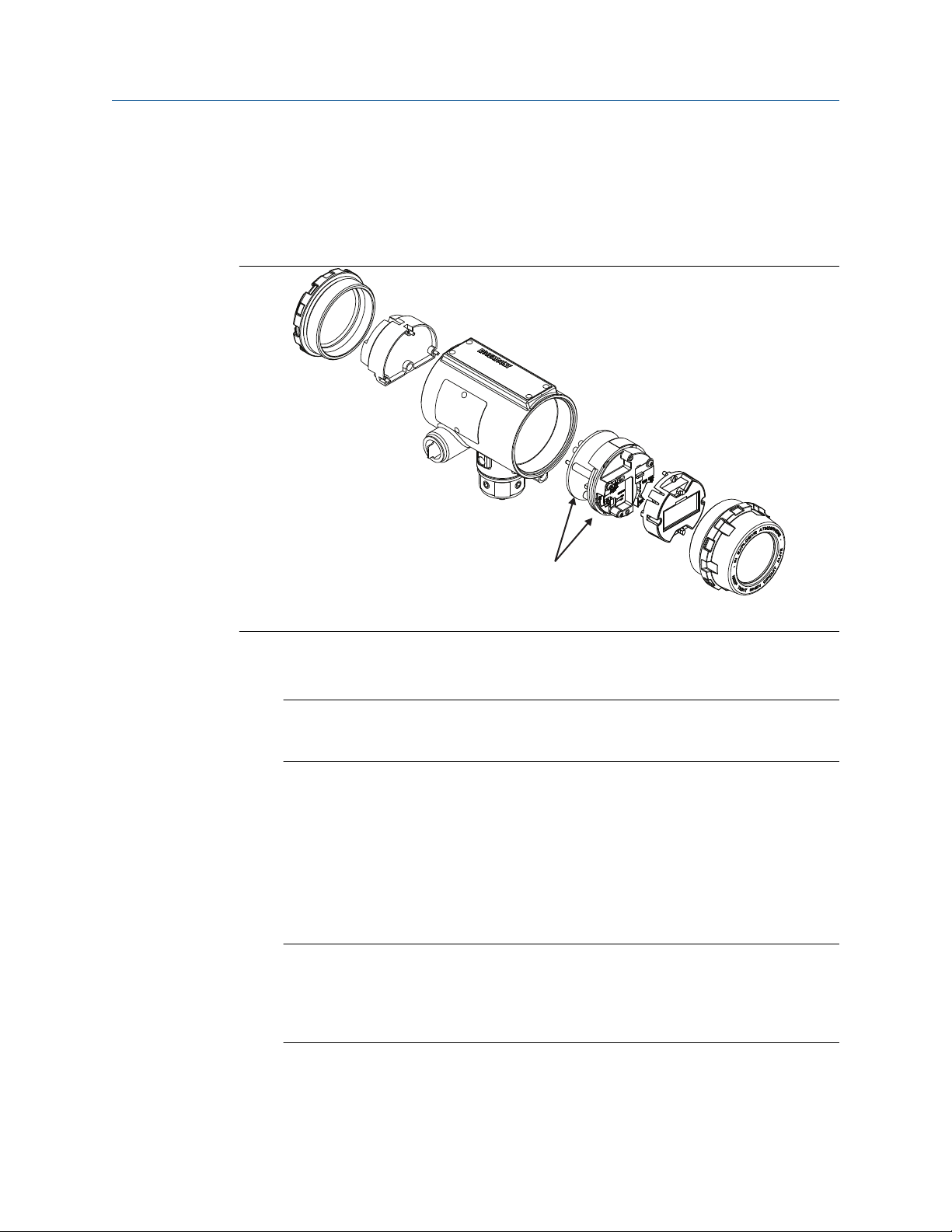
A
Reference Manual
00809-0400-4004 October 2021
• One connector
• Two mounting screws
• Two jumpers
Refer to the following figure when using these steps to install the LCD indicator:
Maintenance
A. Electronics board
1. If the flowmeter is installed in a loop, secure the loop and disconnect the power.
2. Remove the flowmeter cover on the electronics side.
Note
The circuit board is electrostatically sensitive. Be sure to observe handling
precautions for static-sensitive components.
3. Insert the mounting screws into the LCD indicator.
4. Remove the two jumpers on the circuit board that coincide with the Alarm and the
Security settings.
5. Insert the connector into the Alarm/Security junction.
6. Gently slide the LCD indicator onto the connector and tighten the screws into place.
7. Insert jumpers into ALARM and SECURITY positions on the face of the LCD indicator.
8. Attach the extended cover and tighten at least one-third turn past O-ring contact.
Note
The indicator may be installed in 90-degree increments for easy viewing. Mounting
screws may need to be installed in the alternative holes based on LCD display
orientation. One of the four connectors on the back of the indicator assembly must
be positioned to fit into the 10-pin connector on the electronic board stack.
Note the following LCD display temperature limits:
• Operating: –4 to 185 °F (–20 to 85 °C)
Reference Manual 69
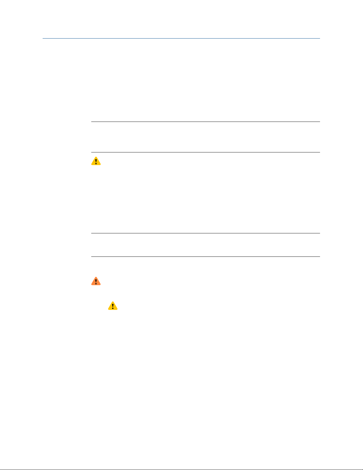
Maintenance Reference Manual
October 2021 00809-0400-4004
• Storage: –50 to 185 °F (–46 to 85 °C)
9.3 Hardware replacement
The following procedures will help you disassemble and assemble the Rosemount 8800D
hardware if you have followed the troubleshooting guide earlier in this section of the
manual and determined that hardware components need to be replaced.
Note
Use only the procedures and new parts specifically referenced in this manual.
Unauthorized procedures or parts can affect product performance and the output signal
used to control a process, and may render the instrument dangerous.
CAUTION
Process should be vented before the meter body is removed from service for
disassembly. Flowmeters should not be left in service once they have been determined
to be inoperable.
9.3.1
Replacing the terminal block in the housing
To replace the field terminal block in the housing, you will need a small screwdriver. Use
the following procedure to replace the terminal block in the housing.
Note
After you replace the terminal block you must also reconfigure (reapply) the HART
message field. See Modbus communication settings.
Remove the terminal block
WARNING
For complete warning information, see Safety messages.
1. CAUTION
Remove power before removing the electronics cover.
Turn off the power to the Rosemount 8800D.
2. Unscrew the cover. Refer to the following figure.
70 Rosemount™ 8800D Series Vortex Flow Meter with Modbus Protocol
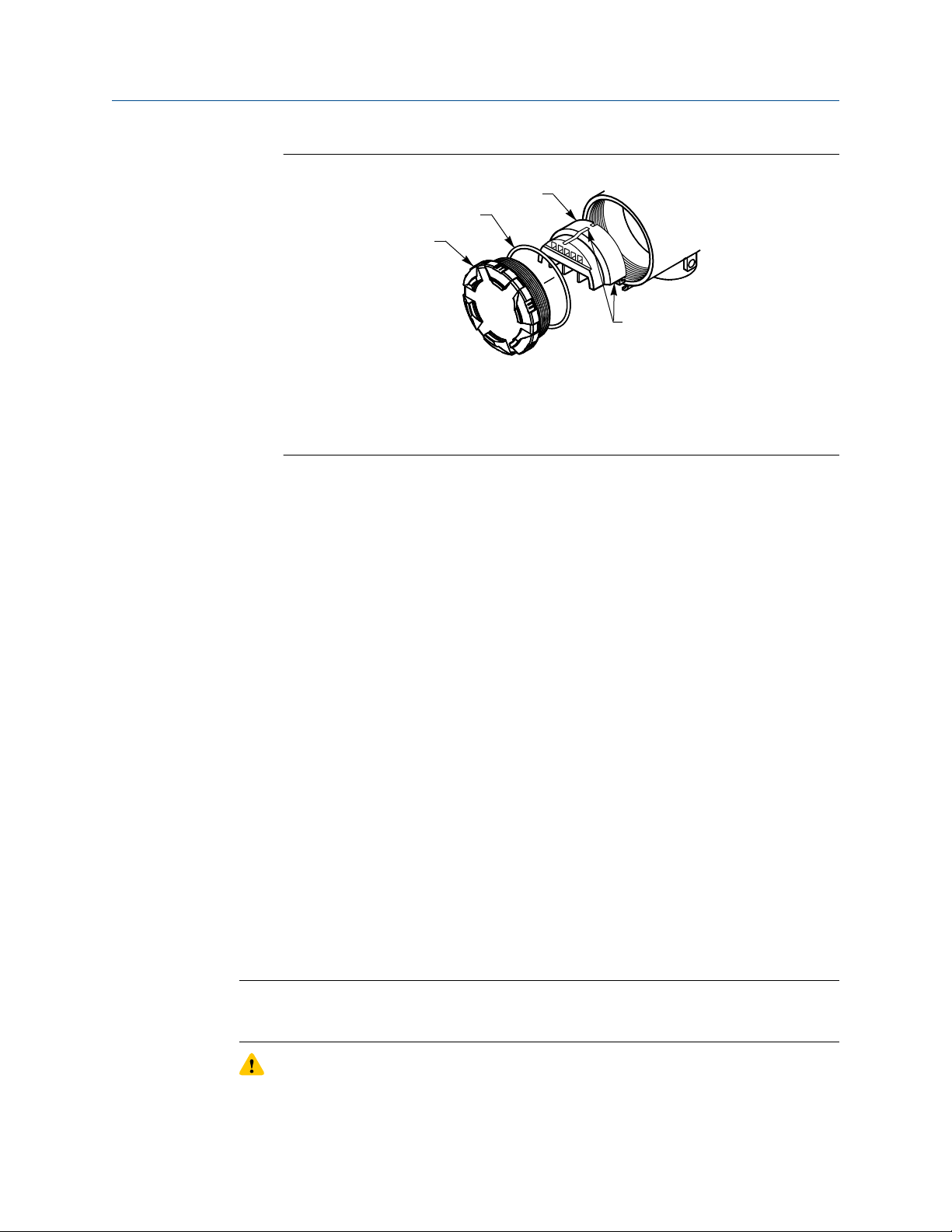
A
B
C
D
Reference Manual
00809-0400-4004 October 2021
Figure 9-2: Terminal block assembly
A. Cover
B. O-ring
C. Terminal block
D. Captive screws (3x)
3. Disconnect the wires from the field terminals. Be sure to secure them out of the
way.
4. Remove the ground screw.
5. Loosen the three captive screws.
6. Pull outward on the terminal block to remove it from the housing.
Maintenance
9.3.2
Install the terminal block
1. Align the socketed holes on the back side of the terminal block over the pins
protruding from the bottom of the housing cavity in the terminal block side of the
electronics housing.
2. Slowly press the terminal block into place. Do not force the block into the housing.
Check the alignment if it does not glide into place.
3. Tighten the three captive screws to anchor the terminal block.
4. Connect the wires to the appropriate field terminals.
5. Reinstall and tighten the ground screw.
6. Screw on and tighten the cover.
Replacing the electronics boards
The Rosemount 8800D electronics boards may need to be replaced if they have been
damaged or otherwise become dysfunctional. Use the following procedures to replace
electronics boards in the Rosemount 8800D. You will need a small Phillips head
screwdriver and pliers.
Note
The electronics boards are electrostatically sensitive. Be sure to observe handling
precautions for static-sensitive components.
Reference Manual 71
CAUTION
Remove power before removing the electronics cover.
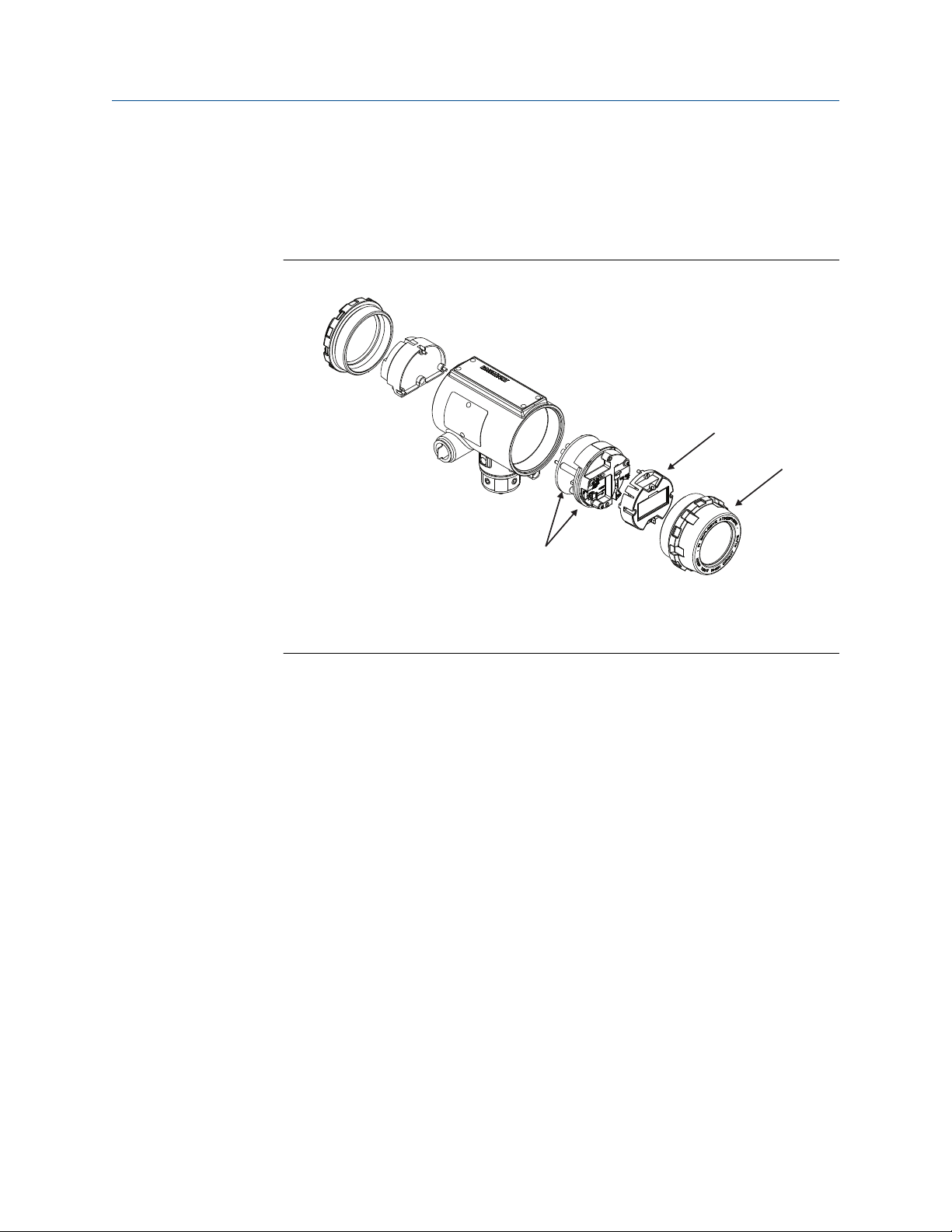
A
B
C
Maintenance
October 2021 00809-0400-4004
Reference Manual
Remove the electronics boards
1. Turn off the power to the Rosemount 8800D.
2. Unscrew and remove the electronics board compartment cover. (Unscrew and
remove the LCD display cover if you have the LCD display option).
Figure 9-3: Electronics Boards Assembly
A. Electronics boards
B. LCD display
C. LCD display cover
3. If the meter has the LCD display option, loosen the two screws.
4. Remove the LCD display and the connector from the electronics board.
5. Loosen the three captive screws that anchor the electronics.
6. Use pliers or a flat head screwdriver to carefully remove the sensor cable clip from
the electronics.
7. Remove thermocouple if applicable.
8. Use the handle molded into the black plastic cover to slowly pull the electronics
boards out of the housing.
Install the electronics boards
1. Verify that power to the Rosemount 8800D is off.
2. Align the sockets on the bottom of the two electronics boards over the pins
protruding from the bottom of the housing cavity.
3. Carefully guide the sensor cable through the notches on the edge of the circuit
boards.
4. Slowly press the boards into place. Do not force the boards down. Check the
alignment if they do not glide into place. Carefully insert sensor cable clip into
electronics board.
5. Tighten the three captive screws to anchor the two electronics boards. Ensure that
the SST washer is under the screw in the 2 o’clock position.
72 Rosemount™ 8800D Series Vortex Flow Meter with Modbus Protocol

Reference Manual
00809-0400-4004 October 2021
6. Reinsert the alarm and security jumpers into the correct location.
7. Re-install the thermocouple if applicable.
8. If the meter has LCD display option, insert the connector header into the LCD
display board.
a) Remove jumpers from the electronics board.
b) Put the connector through the bezel on the electronics board.
c) Carefully press the LCD display onto the electronics board.
d) Tighten the two screws that retain the LCD display.
e) Insert the alarm and security jumpers in the correct location.
9. Replace the electronics board compartment cover.
Maintenance
9.3.3
Replacing the electronics housing
The Rosemount 8800D electronics housing can be replaced easily when necessary. Use
the following procedure:
Tools needed
• 5/32 inch (4 mm) hex wrench
• 5/16 inch (8 mm) open end wrench
• Screwdriver to disconnect wires
• Tools to disconnect conduit
Note
Remove power before removing the electronics housing.
Remove the electronics housing
1. Turn off the power to the Rosemount 8800D.
2. Remove the terminal block side cover.
3. Disconnect the wires and conduit from the housing.
4. Use a 5/32 inch (4 mm) hex wrench to loosen the housing rotation screws (at the
base of the electronics housing) by turning screws clockwise (inward) until they
clear the bracket.
5. Slowly pull the electronics housing no more than 1.5 inch (40 mm) from the top of
the support tube.
6. Loosen the sensor cable nut from the housing with a 5/16 inch (8 mm) open end
wrench.
Note
Lift the electronics housing until the sensor cable nut is exposed. Do not pull the
housing more than 1.5 inch (40 mm) from the top of the support tube. Damage to
the sensor may occur if this sensor cable is stressed.
Reference Manual 73

Maintenance
October 2021 00809-0400-4004
Reference Manual
Install the electronics housing
1. Verify that power to the Rosemount 8800D is off.
2. Screw the sensor cable nut onto the base of the housing.
3. Tighten the sensor cable nut with a 5/16 inch (8 mm) open end wrench.
4. Place the electronics housing into the top of the support tube.
5. Use a hex wrench to turn the three hex socket screws counterclockwise (outward)
to engage support tube.
6. Place the access cover on the support tube (if applicable).
7. Tighten the screw on the access cover.
8. Connect conduit and wires.
9. Replace the terminal block cover.
10. Apply power.
9.3.4
Replacing the sensor
The sensor for the Rosemount 8800D is a sensitive instrument that should not be removed
unless there is a problem with it. If you must replace the sensor, follow these procedures
closely. Consult technical support before removing the sensor.
Note
Be sure to fully check all other troubleshooting possibilities before removing the sensor.
Do not remove the sensor unless it is determined that a problem exists with the sensor
itself. The sensor may not fit on the post if it is removed and replaced more than two or
three times, or replaced incorrectly.
Also, please note that the sensor is a complete assembly and cannot be further
disassembled.
Tools needed
• 5/32 inch (4 mm) hex wrench
• 5/16 inch (8 mm) open end wrench
• 7/16 inch (11 mm) open end wrench
• ¾ inch (19 mm) open end wrench — for 3 inch (80 mm) and 4 inch (100 mm) SST
wafers
• 1-1/8 inch (28 mm) open end wrench (for all other models)
• Suction or compressed air device
• Small, soft bristle brush
• Cotton swabs
• Appropriate cleaning liquid: water or cleaning agent
Removing the sensor
The following procedure applies to flowmeters equipped with a removable support tube.
74 Rosemount™ 8800D Series Vortex Flow Meter with Modbus Protocol

Reference Manual Maintenance
00809-0400-4004 October 2021
Note
Sensor cavity could contain line pressure if an abnormal failure has occurred inside the
meter body. For complete warning information, see Safety messages.
1. If the meter body is not a CriticalProcess™ Vortex (CPA Option) proceed to Step 6.
2. Welded onto the side of the meter body is a valve. Move any nearby equipment
from the line of sight of the valve tube, if possible. Protect other equipment with
shielding, cover, or other type of protection.
3. Position all personnel away from the line of sight of the valve tube.
Note
There are numerous tube fittings that could connect to the tube if there is a need to
drain away process material. The tube on the valve has a 0.188 in (4.8 mm) OD with
a 0.035 in (0.9 mm) wall thickness.
4. Using a 7/16 in (11 mm) open end wrench, slowly loosen the valve nut. Back out the
nut until it stops. There is a set screw which prevents the nut from being completely
removed.
5. Process fluid venting from the valve tube indicates that there is process fluid in the
sensor cavity.
Option Description
If there is no process fluid in
Continue to Step 7.
the sensor cavity
If there is process fluid in the
sensor cavity
Immediately re-tighten the valve nut until process
fluid stops venting. Do not tighten any further.
Stop and contact your technical support. The
meter body may need to be replaced.
6. De-pressurize the flow line.
7. Remove the electronics housing (see Replacing the electronics housing).
8. Loosen the four support tube anchor bolts with a 7/16 in (11 mm) open end
wrench.
Reference Manual 75
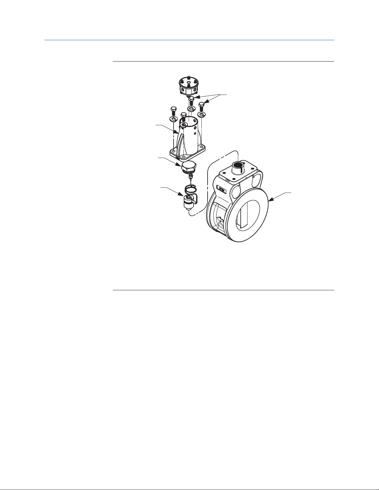
A
B
C
D
E
Maintenance
Reference Manual
October 2021 00809-0400-4004
Figure 9-4: Removable support tube assembly
A. Removable support tube
B. Sensor nut
C. Sensor
D. Anchor bolts
E. Meter body
9. Remove the support tube.
10. Loosen and remove the sensor nut from the sensor cavity with a 1-1/8 in (28 mm)
open end wrench.
Use a 3/4 in (19 mm) open end wrench for 3 in (80 mm) and 4 in (100 mm) SST
wafers.
11. Lift the sensor from the sensor cavity. Be very careful to lift the sensor straight up.
Do not rock, twist, or tilt the sensor during removal; this will damage the
engagement diaphragm.
12. If Critical Process (CPA option) is present, tighten the valve to insure it is closed after
the new Vortex sensor is installed. It is recommended that the nut be torqued to 50
in-lbs (5.7 N-m). Over tightening the valve nut could compromise its ability to seal.
Clean the sealing surface
Before installing a sensor in the meter body, clean the sealing surface by completing the
following procedure.
76 Rosemount™ 8800D Series Vortex Flow Meter with Modbus Protocol
The metal o-ring on the sensor is used to seal the sensor cavity in the event that process
fluid should corrode through the meter body and enter the sensor cavity. Be sure not to

A
Reference Manual Maintenance
00809-0400-4004 October 2021
scratch or otherwise damage any part of the sensor, sensor cavity, or sensor nut threads.
Damage to these parts may require replacement of the sensor or meter body, or may
render the flowmeter dangerous.
Note
If you are installing a sensor that has been used before, clean the metal o-ring on the
sensor using the procedure below. If you are installing a newly purchased sensor, cleaning
the o-ring is not necessary.
Figure 9-5: O-Ring Sealing Surface in Sensor Cavity
A. Sealing surface
1. Use a suction or compressed air device to remove any loose particles from the
sealing surface and other adjacent areas in the sensor cavity. See Figure 9-5.
Note
Do not scratch or deform any part of the sensor, sensor cavity, or sensor nut
threads.
2. Carefully brush the sealing surface clean with a soft bristle brush.
3. Moisten a cotton swab with an appropriate cleaning liquid.
4. Wipe the sealing surface. Repeat several times if necessary with a clean cotton swab
until there is minimal dirt residue picked up by the cotton swab.
Install the sensor
1. Carefully place sensor over the post in the sensor cavity.
2. Ensure that the sensor is centered on the post. See Figure 9-6 and Figure 9-7.
Note
If the sensor is installed in a high temperature application place the sensor in the
sensor cavity and wait for it to come up to temperature before seating the sensor
on the post.
Reference Manual 77

A
B
C
E
D
A
B
C
D
Maintenance
Reference Manual
October 2021 00809-0400-4004
Figure 9-6: Sensor installation – improper alignment (before seating)
A. Top view of flowmeter
B. Sensor
C. Sensor cavity in flowmeter
D. Sensor not properly aligned
E. Sensor center line is not aligned with flowmeter center line. Damage to sensor
will occur.
Figure 9-7: Sensor installation – proper alignment (before seating)
A. Top view of flowmeter
B. Sensor
C. Sensor cavity in flowmeter
D. Sensor center line must be aligned with flowmeter center line.
78 Rosemount™ 8800D Series Vortex Flow Meter with Modbus Protocol

A
B
C
Reference Manual
00809-0400-4004 October 2021
3. Sensor should remain as close to vertical as possible when applying force to seat.
See Figure 9-8.
Figure 9-8: Sensor installation – applying force
A. Pressure
B. Sensor center line must be aligned with flowmeter center line
C. Sensor properly seated
Maintenance
9.3.5
4. Manually push down on the sensor by applying equal pressure for engagement onto
the post.
5. Screw the sensor nut into the sensor cavity. Tighten the nut with a 1-1/8 inch (28
mm) open end torque wrench to 32 ft-lbs (43.4 N-m) (50 ft-lbs [67.8 N-m] for ANSI
1500 meter body).
Use a 3/4 inch (19 mm) open end wrench for 3 inch (80 mm) and 4 inch (100 mm)
SST wafers. Do not over-tighten the sensor nut.
6. Replace the support tube.
7. Tighten the four bolts that anchor the support tube in place with a 7/16 inch (11
mm) open end wrench.
8. Install the flowmeter electronics housing. See Replacing the electronics housing.
Remote electronics procedures
If the Rosemount 8800D electronics housing is mounted remotely, some replacement
procedures are different than for the flowmeter with integral electronics. The following
procedures are identical:
• Replacing the terminal block in the housing.
• Replacing the electronics boards .
• Replacing the sensor.
Disconnect the coaxial cable at the meter
1. Remove the access cover on the meter body support tube if present.
2. Loosen the three housing rotation screws at the base of the meter adapter with a
Reference Manual 79
5/32 inch (4 mm) hex wrench by turning the screws clockwise (inward) until they
clear the bracket.

A
B
C
D
E
F
G
H
I
Maintenance
Reference Manual
October 2021 00809-0400-4004
3. Slowly pull the meter adapter no more than 1.5 inch (40 mm) from the top of the
support tube.
4. Loosen and disconnect the sensor cable nut from the union using a 5/16 inch (8
mm) open end wrench.
Note
Do not pull the adapter more than 1.5 inch (40 mm) from the top of the support
tube. Damage to the sensor may occur if the sensor cable is stressed.
Figure 9-9: Coaxial Cable Connections
A. ½ NPT conduit adapter or cable gland (supplied by customer)
B. Coaxial cable
C. Meter adapter
D. Union
E. Washer
F. Nut
G. Sensor cable nut
H. Support tube
I. Meter body
Detach the meter adapter
Use the following steps if it is necessary to remove the coaxial cable.
1. Loosen and remove the two screws that hold the union onto the meter adapter and
pull the union away from the adapter.
2. Loosen and remove the sensor cable nut from the other end of the union.
80 Rosemount™ 8800D Series Vortex Flow Meter with Modbus Protocol

Reference Manual Maintenance
00809-0400-4004 October 2021
3. Loosen and disconnect the conduit adapter or cable gland from the meter adapter.
Attach the meter adapter
1. If you are using a conduit adapter or cable gland, slide it over the plain end of the
coaxial cable (the end without a ground wire).
2. Slide the meter adapter over the coaxial cable end.
3. Use a 5/16 inch (8 mm) open end wrench to securely tighten the sensor cable nut
onto one end of the union.
4. Place the union onto the two screws extending out of the meter adapter and
tighten the two screws.
Connect the coaxial cable at the meter body
1. Pull the sensor cable out of the support tube slightly and securely tighten the sensor
cable nut onto the union.
Note
Do not stretch the sensor cable over 1.5 inch (40 mm) beyond the top of the
support tube. Damage to the sensor may occur if the sensor cable is stressed.
2. Place the meter adapter into the top of the support tube and line up the screw
holes.
3. Use a hex wrench to turn the three adapter screws counterclockwise (outward) to
engage the support tube.
4. Replace the access cover on the support tube — 6 inch (152.4 mm) to 8 inch (203.2
mm) wafer style only.
5. Tighten the conduit adapter or cable gland into the meter adapter.
Remove the coaxial cable from the electronics housing
1. Loosen the two housing screws from the housing adapter.
2. Remove the housing adapter from the housing.
3. Loosen and remove the coaxial cable nut from the base of the electronics housing.
4. Remove the coaxial cable ground connection from the housing base by loosening
the housing base screw that is connecting it to the housing base.
5. Loosen the conduit adapter (or cable gland) from the housing adapter.
Reference Manual 81

A
B
C
D
F
E
G
Maintenance Reference Manual
October 2021 00809-0400-4004
Figure 9-10: Remote electronics exploded view
A. Ground connection
B. Housing base screw
C. Housing adapter
D. Housing adapter screws
E. Conduit adapter (optional—supplied by customer)
F. Coaxial cable nut
G. Electronics housing
Attach the coaxial cable
1. Route the coaxial cable through the conduit (if you are using conduit).
2. Place a conduit adapter over the end of the coaxial cable.
3. Remove the housing adapter from the electronics housing (if attached).
4. Slide the housing adapter over the coaxial cable.
5. Remove one of the four housing base screws that is in closest proximity to the
ground connection.
6. Re-install the housing base screw by passing it through the ground connection.
7. Attach and securely tighten the coaxial cable nut to the connection on the
electronics housing.
8. Align the housing adapter with the housing base and attach with the two housing
adapter screws.
9. Tighten the conduit adapter to the housing adapter.
82 Rosemount™ 8800D Series Vortex Flow Meter with Modbus Protocol

Reference Manual
00809-0400-4004 October 2021
Maintenance
9.3.6 Changing the housing orientation
The entire electronics housing may be rotated in 90 degree increments for better wiring
access or improved viewing of the display.
1. Loosen the screw on the access cover on the support tube (if present) and remove
the cover.
2. Loosen the three accessible housing rotation set screws at the base of the
electronics housing with a 5/32 inch (4 mm) hex wrench by turning the screws
clockwise (inward) until they clear the support tube.
3. Slowly pull the electronics housing out of the support tube.
If the electronics housing is rotated more than 90 degrees and a thermocouple is
present, remove the thermocouple from the transmitter housing. See Temperature
sensor replacement for more information.
4. Unscrew the sensor cable from the housing with a 5/16 inch (8 mm) open end
wrench.
Note
Do not pull the housing more than 1.5 inch (40 mm) from the top of the support
tube until the sensor cable is disconnected. Damage to the sensor may occur if this
sensor cable is stressed.
9.3.7
5. Rotate the housing to the desired orientation.
6. Hold it in this orientation while you screw the sensor cable onto the base of the
housing.
Note
Do not rotate the housing while the sensor cable is attached to the base of the
housing. This will stress the cable and may damage the sensor.
7. If applicable, re-install the thermocouple to the transmitter housing. See
Temperature sensor replacement.
8. Place the electronics housing into the top of the support tube.
9. Use a hex wrench to turn the three accessible housing rotation screws
counterclockwise to engage the support tube.
10. Replace the access cover on the support tube (if present).
11. Tighten the screw on the access cover (if present).
Temperature sensor replacement
Replacement of the temperature sensor should only be necessary in the event of a failure.
Use the following procedure for replacement.
Note
Disconnect power before replacing temperature sensor.
1. Turn off power to the meter.
2. Remove temperature sensor from meter body by using a ½ inch (13 mm) open end
wrench.
Reference Manual 83

Maintenance
October 2021 00809-0400-4004
Note
Use plant approved procedure for removing a temperature sensor from a
thermowell.
3. Remove temperature sensor from electronics by using a 2.5 mm hex wrench to
remove hex socket screw from electronics.
4. Gently pull temperature sensor from electronics.
Note
This will expose the electronics to the atmosphere.
5. Insert new temperature sensor into electronics housing using care to align pin and
cap head screw to align connector pins.
6. Tightening cap head screw with 2.5 mm hex wrench.
7. Slide bolt and ferrule assembly onto temperature sensor and hold into place.
8. Insert temperature sensor into hole in bottom of meter body until it reaches the
bottom of the hole. Hold it in place and tighten bolt with ½ inch (13 mm) open end
wrench until 3/4 turns past finger tight to seat ferrule.
9. Reapply power to the Rosemount 8800D.
Reference Manual
9.4 Return of material
To expedite the return process, call the Rosemount North American Response Center at
800-654-RSMT (7768) toll-free number. This center, available 24 hours a day, will assist
you with any needed information or materials.
The center will ask for product model and serial numbers, and will provide a Return
Material Authorization (RMA) number. The center will also ask for the name of the process
material to which the product was last exposed.
CAUTION
People who handle products exposed to a hazardous substance can avoid injury if they
are informed and understand the hazard. If the product being returned was exposed to
a hazardous substance as defined by OSHA, a copy of the required Material Safety Data
Sheet (MSDS) for each hazardous substance identified must be included with the
returned goods.
The Rosemount North American Response Center will detail the additional information
and procedures necessary to return goods exposed to hazardous substances.
Toll-free assistance numbers
Within the United States, Emerson Process Management has two toll-free assistance
numbers:
Technical support, quoting, and order-related questions:
1-800-522-6277 (7:00 am to 7:00 pm CST)
North American Response Center—Equipment service needs:
1-800-654-7768 (24 hours—includes Canada)
84 Rosemount™ 8800D Series Vortex Flow Meter with Modbus Protocol

Reference Manual Maintenance
00809-0400-4004 October 2021
Outside of the United States, contact your local an Emerson Flow Sales Representative .
Reference Manual 85

Maintenance Reference Manual
October 2021 00809-0400-4004
86 Rosemount™ 8800D Series Vortex Flow Meter with Modbus Protocol
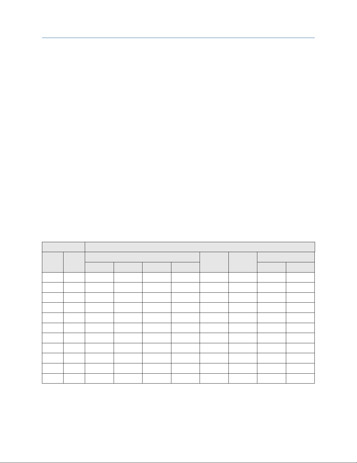
Reference Manual Product Specifications
00809-0400-4004 October 2021
A Product Specifications
A.1 Physical specifications
Rosemount vortex flow meters are designed to the standards defined in ASME B31.3. This
standard is used as the basis for all of our other pressure vessel certifications such as CRN
and PED.
Process fluids
Liquid, Gas, and Steam applications. Fluids must be homogeneous and single-phase.
Flow calibration
Every Emerson Vortex flowmeter is water calibrated and given a unique calibration
number called a reference K-factor. Emerson flow labs use traceable calibrations that
reference internationally recognized standards such as NIST in the United States and
Mexico, National Institute of Standards in China, and ISO 10725 in Europe.
Theoretical and experimental data have shown that the K-factor is independent of fluid
density and viscosity, proving the K-factor is applicable in all types of fluid—liquid, gas and
steam. The K-factor is a function of the shedder bar and meter geometry.
Line sizes and pipe schedules
Table A-1: Line sizes by process connection type
Line size Process connection type (✓ indicates availability)
Inch DIN Flanged Wafer Weld-end Threaded
Standard Dual Reducer Quad Standard Reducer
0.5 15 ✓ ✓ ✓ ✓ ✓
1 25 ✓ ✓ ✓ ✓ ✓ ✓ ✓
1.5 40 ✓ ✓ ✓ ✓ ✓ ✓ ✓
2 50 ✓ ✓ ✓ ✓ ✓ ✓ ✓ ✓
3 80 ✓ ✓ ✓ ✓ ✓ ✓
4 100 ✓ ✓ ✓ ✓ ✓ ✓
6 150 ✓ ✓ ✓ ✓ ✓ ✓
8 200 ✓ ✓ ✓ ✓ ✓ ✓
10 250 ✓ ✓ ✓ ✓ ✓
12 300 ✓ ✓ ✓ ✓ ✓
14 350 ✓
Process pipe schedules
Meters will be shipped from the factory at the Schedule 40 default value unless otherwise
specified. The value can be changed in the field if necessary.
Reference Manual 87

Product Specifications Reference Manual
October 2021 00809-0400-4004
For a weld-end style meter, see Table A-5.
Pressure limits
Table A-2: Flanged/Dual/Quad style meter
ASME 16.5 EN1092-1 JIS
Class 150 PN 10 10K
Class 300 PN 16 20K
Class 600 PN 25 40K
Class 900 PN 40
Class 1500 PN 63
PN 100
PN 160
Table A-3: Reducer style meter
ASME 16.5 EN1092-1
Class 150 PN 10
Class 300 PN 16
Class 600 PN 25
Class 900 PN 40
Class 1500 PN 63
Table A-4: Wafer style meter
ASME 16.5 EN1092-1 JIS
Class 150 PN 10 10K
Class 300 PN 16 20K
Class 600 PN 25 40K
PN 40
PN 63
PN 100
Table A-5: Weld-end/Threaded-end style meter
PN 100
PN 160
W1 W4 W8/T8 W9/T9
Mating pipe
schedule:
88 Rosemount™ 8800D Series Vortex Flow Meter with Modbus Protocol
Schedule 10 Schedule 40 Schedule 80 Schedule 160

Reference Manual Product Specifications
00809-0400-4004 October 2021
Table A-5: Weld-end/Threaded-end style meter (continued)
W1 W4 W8/T8 W9/T9
Pressure rating for
1 inch to 4 inch
sizes:
Pressure rating for
6 inch to 12 inch
sizes:
720 psig
(4.96 MPa-g)
N/A 720 psig
1,440 psig
(9.93 MPa-g)
(4.96 MPa-g)
2,160 psig
(14.9 MPa-g)
1,440 psig
(9.93 MPa-g)
(24.8 MPa-g)
(14.9 MPa-g)
Temperature limits
Table A-6: Vortex sensor temperature limits
Vortex sensor Temperature limit
Standard –40 °F to +450 °F (–40 °C to +232 °C)
Extended –330 °F to +800 °F (–201 °C to +427 °C)
(1)
Severe
(1)
The meter body and sensor, in remote mount configurations, is functionally rated to
–330 °F to +800 °F (–201 °C to +427 °C)
+842 °F process temperature. Process temperature may be further restricted depending
on hazardous area options and PED certificates. Consult applicable certificates for
particular installation limits.
–320 °F to 800 °F (–196 to +427 °C) for European Pressure Equipment Directive (PED),
Contact an Emerson Flow representative (see back page).
The Super Duplex material of construction is limited to use in applications with process
temperatures from –40 to +450 °F (–40 to +232 °C). Contact an Emerson Flow
representative (see back page).
3,600 psig
2,160 psig
Table A-7: Temperature sensor temperature limits
Temperature sensor Temperature limit
Type N thermocouple –40 °F to +842 °F (–40 °C to +450 °C)
(1) Meets ASTM E230/E230M-17 Special Tolerance Standard.
(1)
Table A-8: Electronics temperature limits (remotely-mounted transmitter)
Ambient operating temperature range –58 °F to +185 °F (–50 °C to +85 °C)
Ambient operating temperature range with LCD
—Local Indicator
Storage temperature range –58 °F to +250 °F (–50 °C to +121 °C)
Storage temperature range with LCD –50 °F to +185 °F (–46 °C to +85 °C)
(1) LCD contrast may be affected below –4 °F (–20 °C).
(1)
–40 °F to +185 °F (–40 °C to +85 °C)
Table A-9: Electronics temperature limits (integrally-mounted transmitter)
Operating and storage
temperature range, with and
without LCD
Same as remotely-mounted transmitter. See Table A-8.
However, high process temperature lowers the maximum
allowable ambient temperature. See Figure A-1.
Reference Manual 89

br)br&
br)br&
br)br&
br)br&
br)br&
br)br&
br)br&
br)
br)br&
br)br&
br)br&
br)br&
br)br&
br)br&
br)br&
br)br&
br)br&
br)br&
$PELHQWWHPSHUDWXUH
3URFHVVWHPSHUDWXUH
7HPSHUDWXUH
OLPLWIRUKRXVLQJ
Product Specifications Reference Manual
October 2021 00809-0400-4004
Table A-9: Electronics temperature limits (integrally-mounted transmitter)
(continued)
Maximum process temperature Interdependent with ambient temperature. Figure A-1 indicates
the combined ambient and process temperature limits under
which the electronics temperature can be maintained below the
maximum +185 °F (+85 °C).
Note
The indicated limit is with the integral transmitter directly above
a horizontal pipe, and the pipe insulated with three inches of
ceramic fiber. Other configurations may affect the actual
electronics temperature.
Figure A-1: Maximum ambient/process temperature
limit
90 Rosemount™ 8800D Series Vortex Flow Meter with Modbus Protocol
EMI/RFI effect
• Meets EMC requirements to Directive 2014/30/EU.
• Output error less than ±0.025% of span with twisted pair from 80–1000 MHz for
radiated field strength of 10 V/m.
• 1.4–2.0 GHz for radiated field strength of 3 V/m.
• 2.0–2.7 GHz for radiated field strength of 1 V/m.
• No affect on the values that are being given if using HART digital signal.
• Tested per EN61326.
Humidity limits
Operates in 0–95% relative humidity under noncondensing conditions (tested to IEC
60770, Section 6.2.11).

Reference Manual Product Specifications
00809-0400-4004 October 2021
Remote transmitter mounting hardware and cables
• Mounting hardware is provided.
• The transmitter and meter body are interconnected by a standard or armored signal
cable assembly.
— Cable length is specified when ordered (see Ordering Information - Single/Dual
Transmitter or Ordering information – Quad transmitter), and it cannot be altered
in the field.
— Standard cable is non-armored and is intended to be run through rigid metal
conduit.
— Armored cable includes glands/adapters to connect the cable to the meter body
and transmitter.
— Both types of cable are flame resistant in accordance with IEC 60322-3.
Tagging
• Standard tags are stainless steel.
• The standard tag is permanently attached to the flowmeter.
• Character height is 1/16 inch (1,6 mm).
• A wired-on tag is available on request.
• Character height on the wire-on tag is 0.236 inch (6 mm).
• Wire on tags can contain five lines with an average of 19 characters per line at standard
character height.
A.2 Performance specifications
The following performance specifications are for all Rosemount models except where
noted. Digital performance specifications applicable to both Digital HART and FOUNDATION
Fieldbus output. Unless stated otherwise, all accuracy specifications include linearity,
hysteresis, and repeatability.
Volume flow accuracy
Table A-10: Volume flow accuracy
Process fluid
Liquids with Reynolds number over 20,000 ±0.65% of rate
Gas and steam with Reynolds number over
15,000
For all process fluids from stated limit to a
Reynolds number of 10,000
Digital and pulse output
±1.0% of rate
From process limit specification to ±2% linear
increase
(1)(2)(3)(4)
(5)(2)
For Reynolds numbers less than 10,000 to 5,000 ±2% to ±6%, linear
(1) 6 inch to 12 inch reducer (150 mm to 300 mm) ±1.0% of rate.
(2) Analog ±0.025% of span
(3) 4 inch (100 mm) Quad, ±0.65% for velocities greater than 5.0 ft/sec (1.5 m/sec), ±1.00% of rate
for velocities less than 5.0 ft/sec (1.5 m/sec)
Reference Manual 91
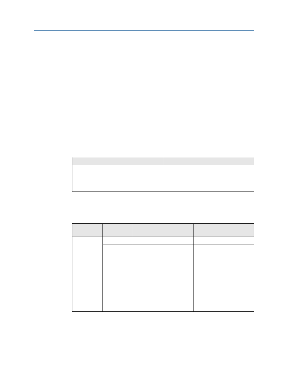
Product Specifications Reference Manual
October 2021 00809-0400-4004
(4) 6 inch (150 mm) Quad, ± 1.00% of rate.
(5) 6 inch to 12 inch reducer (150 mm to 300 mm): ±1.35% of rate.
Accuracy limitations for gas and steam:
• For ½ inch and 1 inch (DN 15 and DN 25); max velocity of 220 ft/s (67.06 m/s)
• For all dual shedder bar design meters: max velocity of 100 ft/s (30.5 m/s)
• For dual shedder bar design meters above 100 ft/s (30.5 m/s) contact an Emerson Flow
representative (see back page).
Volume flow repeatability
±0.1 percent of actual flow rate.
Stability
±0.1% of rate over one year
Process temperature accuracy
Table A-11: Process temperature accuracy by installation type
Installation type Process temperature accuracy
Integral mount 2.2 °F (1.2 °C) or 0.4% of reading, whichever is
greater
Remote mount Add ±0.018 °F/ft (±0.03 °C/m) of uncertainty to
measurement
Temperature sensor accuracy meets ASTM E230/E230M-17 Special Tolerance Standard.
Mass flow accuracy
Table A-12: Mass flow accuracy by process fluid type
Process fluid
type
Steam MTA or MCA Temperature compensation
Liquid (water) MTA and MCA Temperature Compensation ±0.70% of rate up to 500 °F
MV option
code
MPA and MCA Pressure compensation
MCA Pressure and Temperature
Compensation type Accuracy
(1)(2)(3)
Compensation
(1)(2)(3)
(1)
±2.0% of rate (typical)
±1.3% of rate at 30 psia
through 2,000 psia
±1.2% of rate at 150 psia
±1.3% of rate at 300 psia
±1.6% of rate at 800 psia
±2.5% of rate at 2,000 psia
(260 °C)
(4)
Liquid (userdefined)
(1) Temperature range +176 °F to +842 °F (+80 °C to + 450 °C)
(2) Pressure measurement accuracy is ±0.1% of span.
(3) Consult factory accuracy for < 30 psia and > 2,000 psia.
(4) ±0.85% of rate between +500 °F to +600 °F (+260 °C to +316 °C)
92 Rosemount™ 8800D Series Vortex Flow Meter with Modbus Protocol
MTA and MCA Temperature Compensation Dependent on user input

Reference Manual Product Specifications
00809-0400-4004 October 2021
Process temperature effect on K-factor
The compensated K-factor is based on the reference K-factor as compensated for the
given fixed process temperature and wetted materials. Compensated K-factor is
calculated by the electronics.
The percentage change in K-factor for all materials is no greater than ±0.3 per 100 °F
(56 °C).
Table A-13: Ambient temperature effect
Output type Ambient temperature effect
Digital and pulse output No effect
Analog output ±0.1% of span from –58 °F to 185 °F (–50 to
85 °C)
Measurable flow rates
Capable of processing signals from flow applications which meet the Reynolds number
and velocity limitations listed in Table A-14, Table A-15, and Table A-16.
Table A-14: Minimum Measurable Meter Reynolds Numbers
Meter sizes Reynolds number limitations
½ – 4 inch (DN 15 – DN100) 5000 minimum
6 – 12 inch (DN150 – DN300)
Table A-15: Minimum measurable meter velocities
Process Feet per second
(2)
Liquids
(2)
Gases
ρ is the process fluid density at flowing conditions in lb/ft³ for ft/s and kg/m³ for m/s.
(1) Referenced to schedule 40 pipe.
(2) This minimum measurable meter velocity is based on default filter settings.
(1)
36/ρ 54/ρ
36/ρ 54/ρ
Meters per second
(1)
Table A-16: Maximum Measurable Meter Velocities (use the smaller of the two
values)
Process Feet per second
Liquids
(2)
Gases
ρ is the process fluid density at flowing conditions in lb/ft³ for ft/s and kg/m³ for m/s.
90,000/ρ
90,000/ρ
(1)
or 25
or 300
Meters per second
134,000/ρ
134,000/ρ
(1)
or 7.6
or 91.4
(1) Referenced to schedule 40 pipe.
(2) Accuracy limitations for gas and steam for dual-style meters (½ to 4 inch): max velocity of 100
ft/s (30.5 m/s).
Reference Manual 93

Product Specifications Reference Manual
October 2021 00809-0400-4004
Note
Sizing calculations are required to select the proper flow meter size. These calculations
provide pressure loss, accuracy, minimum and maximum flow rate data to guide in proper
selection. Vortex sizing software can be found using the Selection and Sizing tool. The
Selection and Sizing tool can be accessed online or downloaded for offline use using this
link:
www.Emerson.com/FlowSizing
Permanent pressure loss
The approximate permanent pressure loss (PPL) from the flowmeter is calculated for each
application in the Vortex sizing software. Go to the Rosemount 8800D Product Page, and
select Size for detailed sizing on most applications, or complete a Configuration Data
Sheet and contact an Emerson Flow representative (see back page).
The PPL is determined using the equation:
2
4
D
PPL
Permanent pressure loss (psi or kPa)
ρ
Density at operating conditions (lb/ft³ or kg/m³)
ƒ
Q
Actual volumetric flow rate (Gas = ft³/min or m³/hr; Liquid
PPL =
A × ρƒ× Q
= gal/min or l/min)
D
Flowmeter bore diameter (in. or mm)
A
Constant depending on meter style, fluid type, and flow
units. Determined per :
Meter
style
8800DF/W3.4 × 10
8800DR 3.91 ×
8800DD 6.12 ×
8800DQ 6.12 ×
Minimum upstream pressure (liquids)
English units SI units
A
5
10
10
10
liquid
–5
–5
–5
–
A
gas
1.9 × 10
3
2.19 ×
–3
10
3.42 ×
–3
10
3.42 ×
–3
10
A
liquid
–
0.425 118
0.489 136
0.765 212
0.765 212
A
gas
Flow metering conditions that would allow cavitation, the release of vapor from a liquid,
should be avoided. This flow condition can be avoided by remaining within the proper flow
range of the meter and by following appropriate system design.
For some liquid applications, incorporation of a back pressure valve should be considered.
To prevent cavitation, the minimum upstream pressure should be the smaller result of
these two equations:
• 2.9 × ΔP + 1.3 × p
v
• 2.9 × ΔP + pv + 0.5 psia (3.45 kPa)
94 Rosemount™ 8800D Series Vortex Flow Meter with Modbus Protocol

Reference Manual Product Specifications
00809-0400-4004 October 2021
Where:
P
Line pressure five pipe diameters downstream of the meter (psia or kPa abs)
ΔP
Pressure loss across the meter (psi or kPa)
p
Liquid vapor pressure at operating conditions (psia or kPa abs)
v
Vibration effect
High vibration may cause a false flow measurement when there is no flow. The meter
design will minimize this effect, and the factory settings for signal processing are selected
to eliminate these errors for most applications. If an output error at zero flow is still
detected, it can be eliminated by adjusting the low flow cutoff, trigger level, or low-pass
filter. As the process begins to flow through the meter, most vibration effects are quickly
overcome by the flow signal.
Vibration specifications
• Integral aluminum housings, remote aluminum housings, and remote SST housings: At
or near the minimum liquid flow rate in a normal pipe mounted installation, the
maximum vibration should be 0.087 inch (2,21 mm) double amplitude displacement
or 1 g acceleration, whichever is smaller. At or near the minimum gas flow rate in a
normal pipe mounted installation, the maximum vibration should be 0.043 inch
(1,09 mm) double amplitude displacement or ½ g acceleration, whichever is smaller.
• Integral SST housing: At or near the minimum liquid flow rate in a normal pipe
mounted installation, the maximum vibration should be 0.044 inch (1,11 mm) double
amplitude displacement or ⅓ g acceleration, whichever is smaller. At or near the
minimum gas flow rate in a normal pipe mounted installation, the maximum vibration
should be 0.022 inch (0,55 mm) double amplitude displacement or ⅙ g acceleration,
whichever is smaller.
Mounting position effect
Meter will meet accuracy specifications when mounted in horizontal, vertical, or inclined
pipelines. Best practice for mounting in a horizontal pipe is to orient the shedder bar in the
horizontal plane. This will prevent solids in liquid applications and liquid in gas/steam
applications from disrupting the shedding frequency.
Pipe length requirements
Rated accuracy is based on the number of pipe diameters from an upstream disturbance.
No K-factor correction is required if the meter is installed with 35D upstream and 5D
downstream. The value of the K-factor may shift up to 0.5% when the upstream straight
pipe length is reduced down to the minimum recommended 10D. Refer to the Rosemount
8800 Vortex Installation Effects Technical Data Sheet for detailed information on K-factor
correction.
Flow calibration information
Flowmeter calibration and configuration information is provided with every flowmeter. For
a certified copy of flow calibration data, the Q4 option code must be ordered in the model
number.
Reference Manual 95
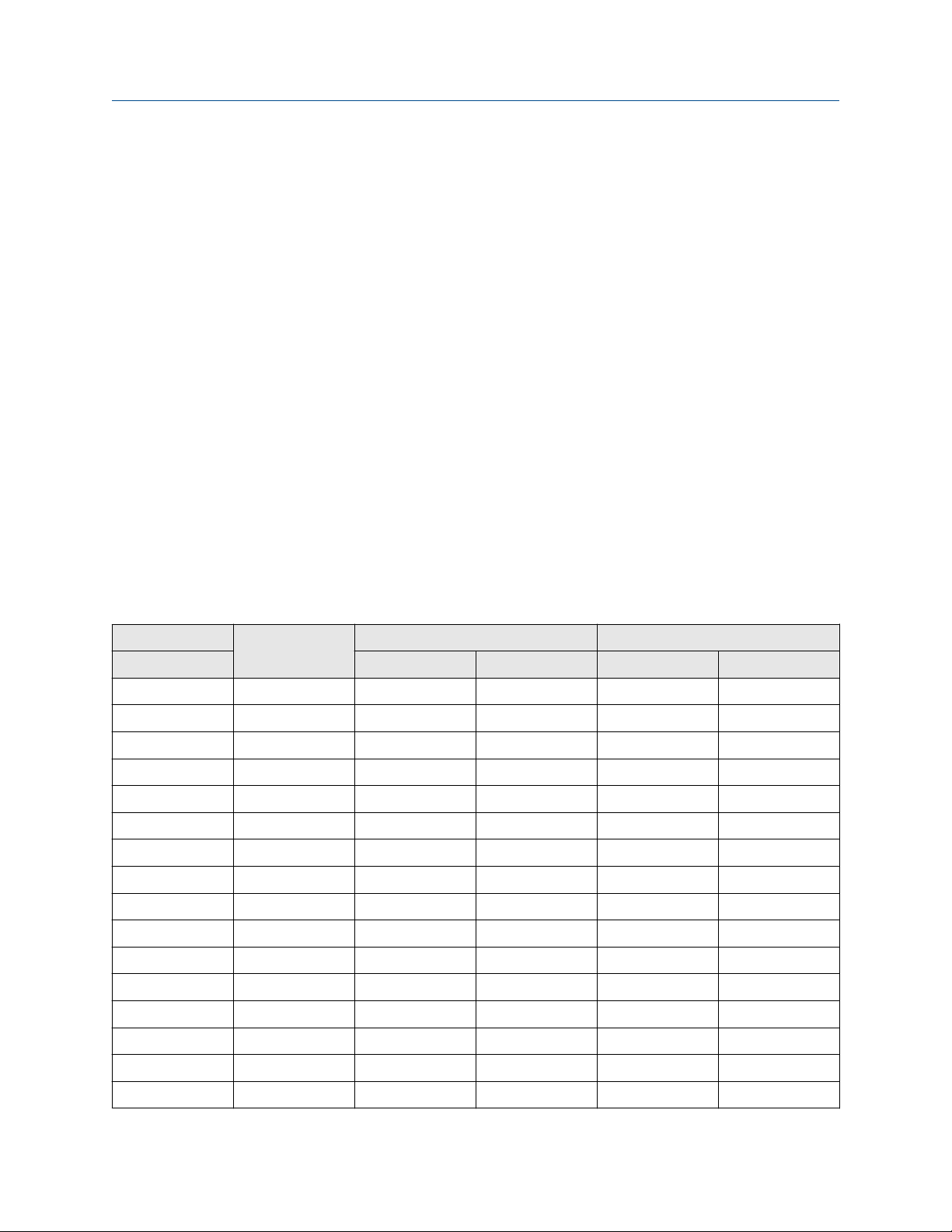
Product Specifications Reference Manual
October 2021 00809-0400-4004
Transient protection
The optional transient terminal block prevents damage to the flowmeter from transients
induced by lightning, welding, heavy electrical equipment, or switch gears. The transient
protection electronics are located in the terminal block.
The transient terminal block meets the following specifications:
• IEEE C62.41 - 2002 Category B
• 3 kA crest (8 × 20 ms)
• 6 kV crest (1.2 × 50 ms)
• 6 kV/0.5 kA (0.5 ms, 100 kHz, ring wave)
A.3 Typical flow rates
This section provides typical flow ranges for some common process fluids with default
filter settings. Consult an Emerson representative (see back page) to obtain a computer
sizing program that describes in greater detail the flow range for an application.
Table A-17 is a reference of pipe velocities that can be measured for the standard
Rosemount 8800D and the reducer Rosemount 8800DR Vortex Meters. It does not
consider density limitations, as described in Table A-14 and Table A-15. Velocities are
referenced in schedule 40 pipe.
Table A-17: Typical pipe velocity ranges for Rosemount 8800D and 8800DR
Process line size Vortex meter
(inches/ DN) (ft/s) (m/s) (ft/s) (m/s)
0.5/ 15 8800DF005 0.70 to 25.0 0.21 to 7.6 6.50 to 250.0 1.98 to 76.2
1/ 25 8800DF010 0.70 to 25.0 0.21 to 7.6 6.50 to 250.0 1.98 to 76.2
8800DR010 0.25 to 8.8 0.08 to 2.7 2.29 to 87.9 0.70 to 26.8
1.5/ 40 8800DF015 0.70 to 25.0 0.21 to 7.6 6.50 to 250.0 1.98 to 76.2
8800DR015 0.30 to 10.6 0.09 to 3.2 2.76 to 106.1 0.84 to 32.3
2/ 50 8800DF020 0.70 to 25.0 0.21 to 7.6 6.50 to 250.0 1.98 to 76.2
8800DR020 0.42 to 15.2 0.13 to 4.6 3.94 to 151.7 1.20 to 46.2
3/ 80 8800DF030 0.70 to 25.0 0.21 to 7.6 6.50 to 250.0 1.98 to 76.2
8800DR030 0.32 to 11.3 0.10 to 3.5 2.95 to 113.5 0.90 to 34.6
4/ 100 8800DF040 0.70 to 25.0 0.21 to 7.6 6.50 to 250.0 1.98 to 76.2
8800DR040 0.41 to 14.5 0.12 to 4.4 3.77 to 145.2 1.15 to 44.3
(1)
Liquid velocity ranges Gas velocity ranges
6/ 150 8800DF060 0.70 to 25.0 0.21 to 7.6 6.50 to 250.0 1.98 to 76.2
8800DR060 0.31 to 11.0 0.09 to 3.4 2.86 to 110.2 0.87 to 33.6
8/ 200 8800DF080 0.70 to 25.0 0.21 to 7.6 6.50 to 250.0 1.98 to 76.2
8800DR080 0.40 to 14.4 0.12 to 4.4 3.75 to 144.4 1.14 to 44.0
10/ 250 8800DF100 0.90 to 25.0 0.27 to 7.6 6.50 to 250.0 1.98 to 76.2
96 Rosemount™ 8800D Series Vortex Flow Meter with Modbus Protocol

Reference Manual Product Specifications
00809-0400-4004 October 2021
Table A-17: Typical pipe velocity ranges for Rosemount 8800D and 8800DR (continued)
Process line size Vortex meter
(inches/ DN) (ft/s) (m/s) (ft/s) (m/s)
8800DR100 0.44 to 15.9 0.13 to 4.8 4.12 to 158.6 1.26 to 48.3
12/ 300 8800DF120 1.10 to 25.0 0.34 to 7.6 6.50 to 250.0 1.98 to 76.2
8800DR120 0.63 to 17.6 0.19 to 5.4 4.58 to 176.1 1.40 to 53.7
(1) Velocity range of the Rosemount 8800DW is the same as Rosemount 8800DF.
(1)
Liquid velocity ranges Gas velocity ranges
Note
Table A-18 is a reference of flow rates that can be measured for the standard Rosemount
8800D and the reducer 8800DR Vortex Meters. It does not consider density limitations, as
described in Table A-14 and Table A-15.
Table A-18: Water flow rate limits for the Rosemount 8800D and 8800DR
Process line size Vortex meter
(1)
Minimum and maximum measurable water flow
(2)
rates
(inches/ DN) Gallons/minute Cubic meters/hour
0.5/ 15 8800DF005 1.76 to 23.7 0.40 to 5.4
1/ 25 8800DF010 2.96 to 67.3 0.67 to 15.3
8800DR010 1.76 to 23.7 0.40 to 5.4
1.5/ 40 8800DF015 4.83 to 158 1.10 to 35.9
8800DR015 2.96 to 67.3 0.67 to 15.3
2/ 50 8800DF020 7.96 to 261 1.81 to 59.4
8800DR020 4.83 to 158.0 1.10 to 35.9
3/ 80 8800DF030 17.5 to 576 4.00 to 130
8800DR030 7.96 to 261.0 1.81 to 59.3
4/ 100 8800DF040 30.2 to 992 6.86 to 225
8800DR040 17.5 to 576 4.00 to 130
6/ 150 8800DF060 68.5 to 2251 15.6 to 511
8800DR060 30.2 to 992 6.86 to 225
8/ 200 8800DF080 119 to 3898 27.0 to 885
8800DR080 68.5 to 2251 15.6 to 511
10/ 250 8800DF100 231 to 6144 52.2 to 1395
8800DR100 119 to 3898 27.0 to 885
12/ 300 8800DF120 391 to 8813 88.8 to 2002
8800DR120 231 to 6144 52.2 to 1395
(1) Velocity range of the 8800DW is the same as 8800DF.
(2) Conditions: 77 °F (25 °C) and 14.7 psia (1.01 bar absolute)
Reference Manual 97

Product Specifications Reference Manual
October 2021 00809-0400-4004
Table A-19: Air flow rate limits at 59 °F (15 °C)
Process pressure Flow
rate
limits
0 psig
(0 bar G)
50 psig
(3,45 bar G)
100 psig
(6,89 bar G)
150 psig
(10,3 bar G)
200 psig
(13,8 bar G)
300 psig
(20,7 bar G)
400 psig
(27,6 bar G)
max
min
max
min
max
min
max
min
max
min
max
min
max
min
Minimum and maximum air flow rates for line sizes 1/2-in./DN 15 through 1in./DN 25
1/2-in./DN 15 1-in./DN 25
Rosemount 8800D Rosemount
8800DR
ACFM ACMH ACFM ACMH ACFM ACMH ACFM ACMH
27.9
4.62
27.9
1.31
27.9
0.98
27.9
0.82
27.9
0.82
27.9
0.82
25.7
0.82
47.3
7.84
47.3
2.22
47.3
1.66
47.3
1.41
47.3
1.41
47.3
1.41
43.9
1.41
Not
Available
Not
Available
Not
Available
Not
Available
Not
Available
Not
Available
Not
Available
Not
Available
Not
Available
Not
Available
Not
Available
Not
Available
Not
Available
Not
Available
Rosemount 8800D Rosemount
8800DR
79.2
9.71
79.2
3.72
79.2
2.80
79.2
2.34
79.2
2.34
79.2
2.34
73.0
2.34
134
16.5
134
6.32
134
4.75
134
3.98
134
3.98
134
3.98
124
3.98
27.9
4.62
27.9
1.31
27.9
0.98
27.9
0.82
27.9
0.82
27.9
0.82
25.7
0.82
47.3
7.84
47.3
2.22
47.3
1.66
47.3
1.41
47.3
1.41
47.3
1.41
43.9
1.41
500 psig
(34,5 bar G)
max
min
23.0
0.82
39.4
1.41
Table A-20: Air flow rate limits at 59 °F (15 °C)
Process pressure Flow
rate
limits
0 psig
(0 bar G)
50 psig
(3,45 bar G)
100 psig
(6,89 bar G)
150 psig
(10,3 bar G)
max
min
max
min
max
min
max
min
Minimum and maximum air Flow rates for line sizes 11/2-in./DN 40 through 2in./DN 50
11/2-in./DN 40 2-in./DN 50
Rosemount 8800D Rosemount
ACFM ACMH ACFM ACMH ACFM ACMH ACFM ACMH
212
18.4
212
8.76
212
6.58
212
5.51
360
31.2
360
14.9
360
11.2
360
9.36
Not
Available
8800DR
79.2
9.71
79.2
3.72
79.2
2.80
79.2
2.34
Not
Available
134
16.5
134
6.32
134
4.75
134
3.98
66.0
2.34
Rosemount 8800D Rosemount
349
30.3
349
14.5
349
10.8
349
9.09
112
3.98
593
51.5
593
24.6
593
18.3
593
15.4
23.0
0.82
8800DR
212
18.4
212
8.76
212
6.58
212
5.51
39.4
1.41
360
31.2
360
14.9
360
11.2
360
9.36
98 Rosemount™ 8800D Series Vortex Flow Meter with Modbus Protocol

Reference Manual Product Specifications
00809-0400-4004 October 2021
Table A-20: Air flow rate limits at 59 °F (15 °C) (continued)
Process pressure Flow
rate
limits
200 psig
(13,8 bar G)
300 psig
(20,7 bar G)
400 psig
(27,6 bar G)
500 psig
(34,5 bar G)
max
min
max
min
max
min
max
min
Minimum and maximum air Flow rates for line sizes 11/2-in./DN 40 through 2in./DN 50
11/2-in./DN 40 2-in./DN 50
Rosemount 8800D Rosemount
ACFM ACMH ACFM ACMH ACFM ACMH ACFM ACMH
212
5.51
198
5.51
172
5.51
154
5.51
360
9.36
337
9.36
293
9.36
262
9.36
Table A-21: Air flow rate limits at 59 °F (15 °C)
Process pressure Flow
rate
limits
Minimum and maximum air flow rates for line sizes 3-in./DN 80 through 4-in./DN
100
3-in./DN 80 4-in./DN 100
Rosemount 8800D Rosemount
8800DR
79.2
2.34
79.2
2.34
73.0
2.34
66.0
2.34
8800DR
134
3.98
134
3.98
124
3.98
112
3.98
Rosemount 8800D Rosemount
8800DR
349
9.09
326
9.09
284
9.09
254
9.09
Rosemount 8800D Rosemount
593
15.4
554
15.4
483
15.4
432
15.4
212
5.51
198
5.51
172
5.51
154
5.51
8800DR
360
9.36
337
9.36
293
9.36
262
9.36
0 psig
(0 bar G)
50 psig
(3,45 bar G)
100 psig
(6,89 bar G)
150 psig
(10,3 bar G)
200 psig
(13,8 bar G)
300 psig
(20,7 bar G)
400 psig
(27,6 bar G)
500 psig
(34,5 bar G)
max
min
max
min
max
min
max
min
max
min
max
min
max
min
max
min
ACFM ACMH ACFM ACMH ACFM ACMH ACFM ACMH
770
66.8
770
31.8
770
23.9
770
20.0
770
20.0
718
20.0
625
20.0
560
20.0
1308
114
1308
54.1
1308
40.6
1308
34.0
1308
34.0
1220
34.0
1062
34.0
951
34.0
349
30.3
349
14.5
349
10.8
349
9.09
349
9.09
326
9.09
284
9.09
254
9.09
593
51.5
593
24.6
593
18.3
593
15.4
593
15.4
554
15.4
483
15.4
432
15.4
1326
115
1326
54.8
1326
41.1
1326
34.5
1326
34.5
1237
34.5
1076
34.5
964
34.5
2253
195
2253
93.2
2253
69.8
2253
58.6
2253
58.6
2102
58.6
1828
58.6
1638
58.6
770
66.8
770
31.8
770
23.9
770
20.0
770
20.0
718
20.0
625
20.0
560
20.0
1308
114
1308
54.1
1308
40.6
1308
34.0
1308
34.0
1220
34.0
1062
34.0
951
34.0
Reference Manual 99

Product Specifications Reference Manual
October 2021 00809-0400-4004
Table A-22: Air flow rate limits at 59 °F (15 °C)
Process pressure Flow
rate
limits
0 psig
(0 bar G)
50 psig
(3,45 bar G)
100 psig
(6,89 bar G)
150 psig
(10,3 bar G)
200 psig
(13,8 bar G)
300 psig
(20,7 bar G)
400 psig
(27,6 bar G)
max
min
max
min
max
min
max
min
max
min
max
min
max
min
Minimum and maximum air flow rates for line sizes 6-in./DN 150 through 8-in./DN
200
6-in./DN 150 8-in./DN 200
Rosemount 8800D Rosemount
8800DR
ACFM ACMH ACFM ACMH ACFM ACMH ACFM ACMH
3009
261
3009
124
3009
93.3
3009
78.2
3009
78.2
2807
78.2
2442
78.2
5112
443
5112
211
5112
159
5112
133
5112
133
4769
133
4149
133
1326
115
1326
54.8
1326
41.1
1326
34.5
1326
34.5
1237
34.5
1076
34.5
2253
195
2253
93.2
2253
69.8
2253
58.6
2253
58.6
2102
58.6
1828
58.6
Rosemount 8800D Rosemount
8800DR
5211
452
5211
215
5211
162
5211
135
5211
135
4862
135
4228
136
8853
768
8853
365
8853
276
8853
229
8853
229
8260
229
7183
229
3009
261
3009
124
3009
93.3
3009
78.2
3009
78.2
2807
78.2
2442
78.2
5112
443
5112
211
5112
159
5112
133
5112
133
4769
133
4149
133
500 psig
(34,5 bar G)
max
min
2188
78.2
3717
133
964
34.5
1638
58.6
3789
136
Table A-23: Saturated steam flow rate limits (assumes steam quality is 100%)
Process pressure Flow
rate
limits
15 psig
(1,03 bar G)
25 psig
(1,72 bar G)
50 psig
(3,45 bar G)
100 psig
(6,89 bar G)
max
min
max
min
max
min
max
min
Minimum and maximum saturated steam flow rates for line sizes 1/2-in./DN 15
through 1-in./DN 25
1/2-in./DN 15 1-in./DN 25
Rosemount 8800D Rosemount
8800DR
lb/hr kg/hr lb/hr kg/hr lb/hr kg/hr lb/hr kg/hr
120
12.8
158
14.0
250
17.6
429
23.1
54.6
5.81
71.7
6.35
113
8.00
194
10.5
Not
Available
Not
Available
Not
Available
Not
Available
Not
Available
Not
Available
Not
Available
Not
Available
Rosemount 8800D Rosemount
342
34.8
449
39.9
711
50.1
1221
65.7
6437
229
155
15.8
203
18.1
322
22.7
554
29.8
2188
78.2
8800DR
120
12.8
158
14.0
250
17.6
429
23.1
3717
133
54.6
5.81
71.7
6.35
113
8.00
194
10.5
100 Rosemount™ 8800D Series Vortex Flow Meter with Modbus Protocol
 Loading...