

Page 1

00809-0100-4725
Model 8732C
Integral Mount
Magnetic
Flowmeter System
English
Rev. BB
Page 2

Page 3
Product Manual
Model 8732C
Integral Mount Magnetic
Flowmeter System
NOTICE
Read this manual before working with the prod uc t. For perso nal and system
safety, and for optimum product performance, make sure you thoroughly
understand the conten ts before installing, using, or maintaining this product.
Within the United States, Rosemount Inc. ha s two tol l-free assistance numbers.
Customer Central: 1-800-999-9307 (
Technical support, quoting, and order-related questions.
North American 1-800-654-7768 (
Response Center: Equipment service needs.
For equipment s ervice or s upport n eeds outs ide th e United State s, cont act your
local Rosemount representative.
7:00 a.m. to 7:00 p.m. CST)
24 hours a day – Includes Canada)
Rosemount Inc.
8200 Market Boulevard
Chanhassen, MN 55317 USA
Tel 1-800-999-9307
Telex 4310012
Fax (612) 949-7001
© Rosemount Inc. 1997. All rights reserved.
http://www.rosemount.com
T
N
I
E
D
R
P
IN
U.
A.
S.
The products described in this document are NOT designed for nuclearqualified applications.
Using non-nuclear qua lifi ed products in applications that require nuclearqualified hardware or products may cause inaccurate readings.
For information on Rosemount nucle ar-qualified products, contact you r local
Rosemount Sales Representative.
Rosemount, the Rosemount logotype, and SMART FAMILY are registered trademarks of Rosemount Inc.
HART is a registered trademark of the HART Communica tion Found atio n.
Cover Photo: 8732-002AB.
Fisher-Rosemount satisfies all obligations coming from legislation
to harmonize product requ ireme n ts in th e Euro pe a n Union.
SNF-0004
Page 4

Page 5
Table of Contents
IMPORTANT
Procedures and instructions in this manual may require special precautions to
ensure the safety of the personnel performing the operations. Information that
raises potential safety issues is indicated by a warning symbol ( ). Refer to the
safety messages listed at the beginning of each section before performing
an operation preceded by this symb o l.
SECTION 1:
Introduction
SECTION 2:
Installation
Manual Scope . . . . . . . . . . . . . . . . . . . . . . . . . . . . . . . . . . . . . . . . . . . 1- 1
System Description . . . . . . . . . . . . . . . . . . . . . . . . . . . . . . . . . . . . . . . 1-2
Safety Messages . . . . . . . . . . . . . . . . . . . . . . . . . . . . . . . . . . . . . . . . . 1-2
Introduction . . . . . . . . . . . . . . . . . . . . . . . . . . . . . . . . . . . . . . . . . . . . . 2-1
Safety Messages . . . . . . . . . . . . . . . . . . . . . . . . . . . . . . . . . . . . . . . . . 2-1
Warnings . . . . . . . . . . . . . . . . . . . . . . . . . . . . . . . . . . . . . . . . . . . . 2-1
Pre-Installation . . . . . . . . . . . . . . . . . . . . . . . . . . . . . . . . . . . . . . . . . . 2-2
Identify Options and Configurations . . . . . . . . . . . . . . . . . . . . . . 2-2
Hardware Switches . . . . . . . . . . . . . . . . . . . . . . . . . . . . . . . . . . . 2-2
Failure Mode . . . . . . . . . . . . . . . . . . . . . . . . . . . . . . . . . . . . . 2-2
Current Output Internally or Externally Powered . . . . . . . 2-2
Transmitter Security . . . . . . . . . . . . . . . . . . . . . . . . . . . . . . . 2-2
Changing Hardware Switch Settings . . . . . . . . . . . . . . . . . . 2-3
Mechanical Considerations . . . . . . . . . . . . . . . . . . . . . . . . . . . . . 2-4
Electrical Considerations . . . . . . . . . . . . . . . . . . . . . . . . . . . . . . . 2-5
Conduit Connections . . . . . . . . . . . . . . . . . . . . . . . . . . . . . . . 2-5
Transmitter Input Power . . . . . . . . . . . . . . . . . . . . . . . . . . . . 2-5
dc Power Requirements . . . . . . . . . . . . . . . . . . . . . . . . . . . . . 2-5
Important User Notes . . . . . . . . . . . . . . . . . . . . . . . . . . . . . . . . . . . . . 2-6
Installation Category . . . . . . . . . . . . . . . . . . . . . . . . . . . . . . . . . . 2-6
Supply Wire Requirements . . . . . . . . . . . . . . . . . . . . . . . . . . . . . 2-6
Disconnects . . . . . . . . . . . . . . . . . . . . . . . . . . . . . . . . . . . . . . . . . . 2-6
Overcurrent Protection . . . . . . . . . . . . . . . . . . . . . . . . . . . . . . . . 2-6
Transmitter Symbols . . . . . . . . . . . . . . . . . . . . . . . . . . . . . . . . . . 2-6
Environmental Considerations . . . . . . . . . . . . . . . . . . . . . . . . . . 2-7
i
Page 6

Installation Procedures . . . . . . . . . . . . . . . . . . . . . . . . . . . . . . . . . . . 2-7
Handling . . . . . . . . . . . . . . . . . . . . . . . . . . . . . . . . . . . . . . . . . . . . 2-7
Flowtube Mounting . . . . . . . . . . . . . . . . . . . . . . . . . . . . . . . . . . . 2-8
Calibration . . . . . . . . . . . . . . . . . . . . . . . . . . . . . . . . . . . . . . . 2-8
Upstream/Downstream Piping . . . . . . . . . . . . . . . . . . . . . . . 2-8
Flowtube Orientation . . . . . . . . . . . . . . . . . . . . . . . . . . . . . . . . . . 2-9
Vertical Installation . . . . . . . . . . . . . . . . . . . . . . . . . . . . . . . . 2-9
Horizontal Installation . . . . . . . . . . . . . . . . . . . . . . . . . . . . . 2-9
Flow Direction . . . . . . . . . . . . . . . . . . . . . . . . . . . . . . . . . . . . . . .2-11
Gaskets . . . . . . . . . . . . . . . . . . . . . . . . . . . . . . . . . . . . . . . . . . . . . 2-11
Flange Bolts . . . . . . . . . . . . . . . . . . . . . . . . . . . . . . . . . . . . . . . . .2-12
Model 8705 . . . . . . . . . . . . . . . . . . . . . . . . . . . . . . . . . . . . . . .2-12
Model 8711 . . . . . . . . . . . . . . . . . . . . . . . . . . . . . . . . . . . . . . .2-13
Grounding . . . . . . . . . . . . . . . . . . . . . . . . . . . . . . . . . . . . . . . . . . .2-15
Model 8705 . . . . . . . . . . . . . . . . . . . . . . . . . . . . . . . . . . . . . . .2-15
Model 8711 . . . . . . . . . . . . . . . . . . . . . . . . . . . . . . . . . . . . . . .2-17
Install Conduit . . . . . . . . . . . . . . . . . . . . . . . . . . . . . . . . . . . . . . .2-19
Power Connections . . . . . . . . . . . . . . . . . . . . . . . . . . . . . . . . . . . .2-19
Options, Considerations, and Procedures . . . . . . . . . . . . . . . . . . . . .2-20
Connect 4–20 mA Loop External Power Source . . . . . . . . . . . . .2-20
Connect Pulse Output Power Source . . . . . . . . . . . . . . . . . . . . .2-21
Connect Auxiliary Output Control . . . . . . . . . . . . . . . . . . . . . . .2-22
Quick Start-Up . . . . . . . . . . . . . . . . . . . . . . . . . . . . . . . . . . . . . . . . . .2-22
Installation Check and Guide . . . . . . . . . . . . . . . . . . . . . . . . . . .2-23
Process Leak Protection (Model 8705 Only) . . . . . . . . . . . . . . . . . . .2-23
Process Leak Containment . . . . . . . . . . . . . . . . . . . . . . . . . . . . .2-24
Relief Valves . . . . . . . . . . . . . . . . . . . . . . . . . . . . . . . . . . . . . . . . .2-25
Field-Removable Electrodes . . . . . . . . . . . . . . . . . . . . . . . . . . . . .2-26
SECTION 3:
Local Operator Interface
The Local Operator Interface (LOI) . . . . . . . . . . . . . . . . . . . . . . . . . . 3-1
Safety Messages . . . . . . . . . . . . . . . . . . . . . . . . . . . . . . . . . . . . . . . . . 3-1
LOI Features . . . . . . . . . . . . . . . . . . . . . . . . . . . . . . . . . . . . . . . . 3-2
LOI Rotation . . . . . . . . . . . . . . . . . . . . . . . . . . . . . . . . . . . . . . . . . 3-3
Data Entry . . . . . . . . . . . . . . . . . . . . . . . . . . . . . . . . . . . . . . . . . . 3-3
LOI Examples . . . . . . . . . . . . . . . . . . . . . . . . . . . . . . . . . . . . . . . . . . . 3-4
Table Value Example . . . . . . . . . . . . . . . . . . . . . . . . . . . . . . . . . . 3-4
Select Value Example . . . . . . . . . . . . . . . . . . . . . . . . . . . . . . . . . . 3-4
LOI Screen Flow . . . . . . . . . . . . . . . . . . . . . . . . . . . . . . . . . . . . . . . . . 3-5
Diagnostic Messages . . . . . . . . . . . . . . . . . . . . . . . . . . . . . . . . . . . . . . 3-6
ii
Page 7

SECTION 4:
Transmitter Functions
Introduction . . . . . . . . . . . . . . . . . . . . . . . . . . . . . . . . . . . . . . . . . . . . . 4-1
Safety Messages . . . . . . . . . . . . . . . . . . . . . . . . . . . . . . . . . . . . . . . . . 4-2
Review Variables . . . . . . . . . . . . . . . . . . . . . . . . . . . . . . . . . . . . . . . . . 4-3
Check Output Variables . . . . . . . . . . . . . . . . . . . . . . . . . . . . . . . . . . . 4-3
Process Variables . . . . . . . . . . . . . . . . . . . . . . . . . . . . . . . . . . 4-3
Basic Configuration . . . . . . . . . . . . . . . . . . . . . . . . . . . . . . . . . . . . . . 4-4
Units . . . . . . . . . . . . . . . . . . . . . . . . . . . . . . . . . . . . . . . . . . . . 4-4
Line Size . . . . . . . . . . . . . . . . . . . . . . . . . . . . . . . . . . . . . . . . . 4-4
Tube Cal. Number . . . . . . . . . . . . . . . . . . . . . . . . . . . . . . . . . 4-4
Upper Range Value . . . . . . . . . . . . . . . . . . . . . . . . . . . . . . . . 4-4
Special Units Configuration . . . . . . . . . . . . . . . . . . . . . . . . . . . . . . . . 4-5
Volume Unit . . . . . . . . . . . . . . . . . . . . . . . . . . . . . . . . . . . . . . 4-5
Base Volume Unit . . . . . . . . . . . . . . . . . . . . . . . . . . . . . . . . . 4-5
Conversion Number . . . . . . . . . . . . . . . . . . . . . . . . . . . . . . . . 4-5
Base Time Unit . . . . . . . . . . . . . . . . . . . . . . . . . . . . . . . . . . . 4-5
Flow Rate Unit . . . . . . . . . . . . . . . . . . . . . . . . . . . . . . . . . . . . 4-5
Analog Output Configuration . . . . . . . . . . . . . . . . . . . . . . . . . . . . . . . 4-6
Upper Range Value (URV) . . . . . . . . . . . . . . . . . . . . . . . . . . . 4-6
Lower Range Value (LRV) . . . . . . . . . . . . . . . . . . . . . . . . . . . 4-6
4–20 mA Output Trim . . . . . . . . . . . . . . . . . . . . . . . . . . . . . . 4-7
Loop Test . . . . . . . . . . . . . . . . . . . . . . . . . . . . . . . . . . . . . . . . . 4-7
Digital Output . . . . . . . . . . . . . . . . . . . . . . . . . . . . . . . . . . . . . . . . . . . 4-8
Auxiliary Output Control . . . . . . . . . . . . . . . . . . . . . . . . . . . 4-8
Pulse Width . . . . . . . . . . . . . . . . . . . . . . . . . . . . . . . . . . . . . . 4-9
Totalizer Configuration . . . . . . . . . . . . . . . . . . . . . . . . . . . . . . . . . . . . 4-11
Totalizer Display . . . . . . . . . . . . . . . . . . . . . . . . . . . . . . . . . . 4-11
Noise Reduction . . . . . . . . . . . . . . . . . . . . . . . . . . . . . . . . . . . . . . . . .4-12
Damping . . . . . . . . . . . . . . . . . . . . . . . . . . . . . . . . . . . . . . . . .4-12
Coil Frequency . . . . . . . . . . . . . . . . . . . . . . . . . . . . . . . . . . . .4-12
Auto Zero . . . . . . . . . . . . . . . . . . . . . . . . . . . . . . . . . . . . . . . .4-12
Low Flow Cutoff . . . . . . . . . . . . . . . . . . . . . . . . . . . . . . . . . . .4-12
Signal Processing . . . . . . . . . . . . . . . . . . . . . . . . . . . . . . . . . .4-12
Signal Processing Control . . . . . . . . . . . . . . . . . . . . . . . . . . .4-13
Number of Samples . . . . . . . . . . . . . . . . . . . . . . . . . . . . . . . .4-13
Maximum Percent Limit . . . . . . . . . . . . . . . . . . . . . . . . . . . .4-13
Time Limit . . . . . . . . . . . . . . . . . . . . . . . . . . . . . . . . . . . . . . .4-13
Calibration . . . . . . . . . . . . . . . . . . . . . . . . . . . . . . . . . . . . . . . . . . . . .4-14
Gain (Electronics) Trim . . . . . . . . . . . . . . . . . . . . . . . . . . . . .4-14
Transmitter Information Configuration . . . . . . . . . . . . . . . . . . . . . .4-15
Transmitter Tag . . . . . . . . . . . . . . . . . . . . . . . . . . . . . . . . . . .4-15
Software Revision Number . . . . . . . . . . . . . . . . . . . . . . . . . .4-15
Descriptor . . . . . . . . . . . . . . . . . . . . . . . . . . . . . . . . . . . . . . . .4-15
Message . . . . . . . . . . . . . . . . . . . . . . . . . . . . . . . . . . . . . . . . .4-15
Date . . . . . . . . . . . . . . . . . . . . . . . . . . . . . . . . . . . . . . . . . . . .4-15
Flowtube Tag . . . . . . . . . . . . . . . . . . . . . . . . . . . . . . . . . . . . .4-15
Flowtube Serial Number . . . . . . . . . . . . . . . . . . . . . . . . . . . .4-15
Liner Material . . . . . . . . . . . . . . . . . . . . . . . . . . . . . . . . . . . .4-16
Electrode Typ e . . . . . . . . . . . . . . . . . . . . . . . . . . . . . . . . . . . .4-16
Electrode Material . . . . . . . . . . . . . . . . . . . . . . . . . . . . . . . . .4-16
Flange Type . . . . . . . . . . . . . . . . . . . . . . . . . . . . . . . . . . . . . .4-16
Flange Material . . . . . . . . . . . . . . . . . . . . . . . . . . . . . . . . . . .4-17
Multidrop Communications . . . . . . . . . . . . . . . . . . . . . . . . . . . . . . . .4-18
Auto Poll . . . . . . . . . . . . . . . . . . . . . . . . . . . . . . . . . . . . . . . . .4-19
Poll Address . . . . . . . . . . . . . . . . . . . . . . . . . . . . . . . . . . . . . .4-19
iii
Page 8

SECTION 5:
Troubleshooting
Basic Troubleshooting . . . . . . . . . . . . . . . . . . . . . . . . . . . . . . . . . . . . . 5-1
Safety Messages . . . . . . . . . . . . . . . . . . . . . . . . . . . . . . . . . . . . . . . . . 5-1
Advanced Troubleshooting . . . . . . . . . . . . . . . . . . . . . . . . . . . . . . . . . 5-3
Process Noise . . . . . . . . . . . . . . . . . . . . . . . . . . . . . . . . . . . . . . . . 5-3
Software Testing . . . . . . . . . . . . . . . . . . . . . . . . . . . . . . . . . . . . . . 5-4
Loop Test . . . . . . . . . . . . . . . . . . . . . . . . . . . . . . . . . . . . . . . . . 5-4
Pulse Test . . . . . . . . . . . . . . . . . . . . . . . . . . . . . . . . . . . . . . . . 5-4
Transmitter Test . . . . . . . . . . . . . . . . . . . . . . . . . . . . . . . . . . 5-4
Flowtube Troubleshooting Procedures . . . . . . . . . . . . . . . . . . . . 5-5
Transmitter Removal Procedure . . . . . . . . . . . . . . . . . . . . . . 5-5
Transmitter Assembly Procedure . . . . . . . . . . . . . . . . . . . . . 5-5
Return of Materials . . . . . . . . . . . . . . . . . . . . . . . . . . . . . . . . . . . . . . . 5-7
SECTION 6:
Model 8732C
Specifications and
Reference Data
SECTION 7:
Model 8705 Specifications
and Reference Data
SECTION 8:
Model 8711 Specifications
and Reference Data
Specifications . . . . . . . . . . . . . . . . . . . . . . . . . . . . . . . . . . . . . . . . . . . 6-1
Functional Specifications . . . . . . . . . . . . . . . . . . . . . . . . . . . . . . . 6-1
Performance Specifications . . . . . . . . . . . . . . . . . . . . . . . . . . . . . 6-3
Physical Specifications . . . . . . . . . . . . . . . . . . . . . . . . . . . . . . . . . 6-4
Ordering Information . . . . . . . . . . . . . . . . . . . . . . . . . . . . . . . . . . . . . 6-4
Model 8732C Spare Parts . . . . . . . . . . . . . . . . . . . . . . . . . . . . . . . . . . 6-5
Specifications . . . . . . . . . . . . . . . . . . . . . . . . . . . . . . . . . . . . . . . . . . . 7-1
Functional Specifications . . . . . . . . . . . . . . . . . . . . . . . . . . . . . . . 7-1
Performance Specifications . . . . . . . . . . . . . . . . . . . . . . . . . . . . . 7-2
Physical Specifications . . . . . . . . . . . . . . . . . . . . . . . . . . . . . . . . . 7-3
Specifications . . . . . . . . . . . . . . . . . . . . . . . . . . . . . . . . . . . . . . . . . . . 8-1
Functional Specifications . . . . . . . . . . . . . . . . . . . . . . . . . . . . . . . 8-1
Performance Specifications . . . . . . . . . . . . . . . . . . . . . . . . . . . . . 8-2
Physical Specifications . . . . . . . . . . . . . . . . . . . . . . . . . . . . . . . . . 8-2
iv
Page 9

APPENDIX A:
HART Communicator
Introduction . . . . . . . . . . . . . . . . . . . . . . . . . . . . . . . . . . . . . . . . . . . . . A-1
Safety Messages . . . . . . . . . . . . . . . . . . . . . . . . . . . . . . . . . . . . . . . . . A-1
HART Communicator Menu Tree. . . . . . . . . . . . . . . . . . . . . . . . . . . . A-2
HART Fast Key Sequence. . . . . . . . . . . . . . . . . . . . . . . . . . . . . . . . . . A-3
Connections and Hardware . . . . . . . . . . . . . . . . . . . . . . . . . . . . . . . . A-4
Basic Features . . . . . . . . . . . . . . . . . . . . . . . . . . . . . . . . . . . . . . . . . . . A-6
Action Keys . . . . . . . . . . . . . . . . . . . . . . . . . . . . . . . . . . . . . . . . . . A-7
Function Keys . . . . . . . . . . . . . . . . . . . . . . . . . . . . . . . . . . . . . . . . A-7
Alphanumeric and Shift Keys . . . . . . . . . . . . . . . . . . . . . . . . . . . A-8
Data Entry . . . . . . . . . . . . . . . . . . . . . . . . . . . . . . . . . . . . . . . A-8
HART Fast Key Feature . . . . . . . . . . . . . . . . . . . . . . . . . . . . . . . A-8
HART Fast Key Example . . . . . . . . . . . . . . . . . . . . . . . . . . . A-8
Menus and Functions . . . . . . . . . . . . . . . . . . . . . . . . . . . . . . . . . . . . . A-9
Main Menu . . . . . . . . . . . . . . . . . . . . . . . . . . . . . . . . . . . . . . . . . . A-9
Online Menu . . . . . . . . . . . . . . . . . . . . . . . . . . . . . . . . . . . . . . . . . A-9
Diagnostic Messages . . . . . . . . . . . . . . . . . . . . . . . . . . . . . . . . . . . . . A-10
APPENDIX B:
Operation Planning
APPENDIX C:
Transmitter
Output Instability
Introduction . . . . . . . . . . . . . . . . . . . . . . . . . . . . . . . . . . . . . . . . . . . . . B-1
Safety Messages . . . . . . . . . . . . . . . . . . . . . . . . . . . . . . . . . . . . . . . . . B-1
Flowtube Site Selection . . . . . . . . . . . . . . . . . . . . . . . . . . . . . . . . B-2
Line Power Access . . . . . . . . . . . . . . . . . . . . . . . . . . . . . . . . . B-2
Bypass Piping . . . . . . . . . . . . . . . . . . . . . . . . . . . . . . . . . . . . . B-2
Process Conditions . . . . . . . . . . . . . . . . . . . . . . . . . . . . . . . . . B-3
Adequate Space . . . . . . . . . . . . . . . . . . . . . . . . . . . . . . . . . . . B-3
Earth Ground . . . . . . . . . . . . . . . . . . . . . . . . . . . . . . . . . . . . . B-3
Low-Noise Environment . . . . . . . . . . . . . . . . . . . . . . . . . . . . B-3
Conductivity . . . . . . . . . . . . . . . . . . . . . . . . . . . . . . . . . . . . . . B-3
Flowtube Orientation . . . . . . . . . . . . . . . . . . . . . . . . . . . . . . . . . . B-4
Upstream Piping Length . . . . . . . . . . . . . . . . . . . . . . . . . . . . B-4
Vertical Installation . . . . . . . . . . . . . . . . . . . . . . . . . . . . . . . . B-4
Horizontal Installation . . . . . . . . . . . . . . . . . . . . . . . . . . . . . B-4
Magnetic Flowmeter Sizing . . . . . . . . . . . . . . . . . . . . . . . . . . . . . B-4
Safety Messages . . . . . . . . . . . . . . . . . . . . . . . . . . . . . . . . . . . . . . . . . C-1
Warnings . . . . . . . . . . . . . . . . . . . . . . . . . . . . . . . . . . . . . . . . . . . . C-1
Procedures . . . . . . . . . . . . . . . . . . . . . . . . . . . . . . . . . . . . . . . . . . . . . . C-2
Auto Zero . . . . . . . . . . . . . . . . . . . . . . . . . . . . . . . . . . . . . . . . . . . . C-2
Signal Processing . . . . . . . . . . . . . . . . . . . . . . . . . . . . . . . . . . . . . C-2
How Does It Really Work? . . . . . . . . . . . . . . . . . . . . . . . . . . . C-3
When Should Signal Processing Be Used? . . . . . . . . . . . . . . C-4
APPENDIX D:
Magnetic Flow
Operating Principles
INDEX
Operating Principle . . . . . . . . . . . . . . . . . . . . . . . . . . . . . . . . . . . . . . D-1
Primary and Secondary Devices . . . . . . . . . . . . . . . . . . . . . . . . . . . . D-2
Series 8700 Magnetic Flowmeter Flowtube . . . . . . . . . . . . . . . . D-2
Series 8712 Magnetic Flowmeter Transmitter . . . . . . . . . . . . . . D-2
Electrical Design . . . . . . . . . . . . . . . . . . . . . . . . . . . . . . . . . . . . . . . . . D-2
Pulsed dc Field Coil Advantages . . . . . . . . . . . . . . . . . . . . . . . . . D-2
v
Page 10

vi
Page 11

Section
1 Introduction
MANUAL SCOPE
This manual provides instructions for installing, configuring,
operating, and troubleshooting the Rosemount Model 8732C
Integral Mount Magnetic Flowmeter System.
Section 2: Installation
provides step by step instructions for installing and starting-up the
Model 8732C Magnetic Flowmeter System.
Section 3: Local Operator Interface
introduces the Model 8732C local operator interface (LOI) and its
function in configuring the Model 8732C.
Section 4: Transmitter Functions
guides you through the software configuration functions for the Model
8732C. Basic configuration covers the functions that are necessary to
get the system up and running as well as special configuration.
Section 5: Troubleshooting
includes troubleshooting tables and software test procedures for
diagnosing and repairing problems with the Model 8732C.
Section 6: Model 8732 Specifications and Reference Data
provides functional, performance, and physical specifications for the
Model 8732C. It also includes ordering information and approvals.
Section 7: Model 8705 Specifications and Reference Data
provides functional, performance, and physical specifications for Model
8705 Flanged Magnetic Flowmeter Flowtubes. It also includes ordering
information and approvals.
Section 8: Model 8711 Specifications and Reference Data
provides functional, performance, and physical specifications for Model
8711 Wafer Magnetic Flowmeter Flowtubes. It also includes ordering
information and approvals.
Appendix A: Hart Communicator
is a detailed summary of the operational features of the HART
Communicator. It includes a menu tree, Fast Key Sequence table,
and other instructions.
Appendix B: Operation Planning
provides guidance for system planning when using a magnetic
flowmeter system.
Appendix C: Transmitter Output Instability
describes the problems of signal noise and the s ignal processing system
of the Rosemount Model 8732C Transmitter.
Appendix D: Magnetic Flow Operating Principles
explains the principles behind Series 8700 System operations,
functions, and design.
1-1
Page 12

Rosemount Model 8732C Integral Mount Magnetic Flowmeter System
SYSTEM DESCRIPTION
SAFETY MESSAGES
A complete magnetic flowmeter system consists of two components: the
Rosemount Model 8732C microprocessor-based integral-mount magnetic
flowmeter transmitter, and a Rosemount Model 8705 or 8711 flowtube.
The flowtube is installed in-line with process piping, either vertically or
horizontally. Coils located on opposite sides of the flowtube create a
magnetic field, and conductive liquid moving through the magnetic
field generates a voltage that is detected by two electrodes.
The transmitter controls the generation of th e mag netic field and
senses the voltage detected by the electrodes. Base d on the se n sed
voltage, the transmitter calculates a flow rate and produces analog
and frequency output signals proportional to this flow rate.
Procedures and instructions in this manual may requ ire spe cial
precautions to ensure the safety of the perso nnel performi ng the
operations. Refer to the safety messages listed at the beginning of
each section before performing any operations.
1-2
Page 13
Section
2 Installation
INTRODUCTION
SAFETY MESSAGES
Warnings
This section covers the installation procedures for the Model 8732C
Magnetic Flowmeter System.
Instructions and procedures in this section may require special
precautions to ensure the safety of the perso nnel performi ng
the operations. Information that raises potential s afety issues
is indicated by a warning symbol ( ). Please refer to the following
safety messages before performing an operation preceded by
this symbol.
Explosions could result in death or serious injury:
• Verify that the operating atmosphere of the flowtube and
transmitter is consistent with the appropriate hazardous
locations certifications.
• Do not remove the transmitter cover in explosive atmospheres
when the circuit is alive.
• Before connecting a HART-based communicator in an explosive
atmosphere, make sure the instruments in the loop are
installed in accordance with intrinsically safe or non-incendive
field wiring practices.
• Both transmitter covers must be fully engaged to meet
explosion-proof requirements.
Failure to follow safe installation a nd servicing guide lines could res ult
in death or serious injury:
• Make sure only qualified personnel perform the installation.
• Do not perform any service other than those contained in this
manual unless qualified.
High voltage that may be present on leads co uld cause
electrical shock:
• Avoid contact with leads and terminals.
2-1
Page 14

Rosemount Model 8732C Integral Mount Magnetic Flowmeter System
PRE-INSTALLATION
Identify Options
and Configurations
Hardware Switches
There are several pre-installation steps that make the installation process
easier. They include identifying the options and configurations that apply
to your application, setting the hardware switches if neces sary, and
consideration of m ech anic al , electr ical , and envir on mental req u iremen ts .
Please remember that the flowtube liner is vulnerabl e to handli ng
damage. Never place anything through the flowtube for the purpose of
lifting or gaining leverage. Liner damage can render the flowtube useless.
Standard application of the Model 8732C includes a 4–20 mA output
and control of the flowtube coils. Other applications may require
one or more of the following configurations or options:
• Multidrop Communications
• Auxiliary Output
• Pulse Output
Additional options may also apply. Be sure to identify the options and
configurations that apply to your situation, and keep a list of them
nearby during the installation and configuration procedures.
The Model 8732C electronics board is equipped with three user-selectable
hardware switches: Failure Alarm Mode, Output Power Source, and
Software Lockout Mode. The standard configurations for these switches
when shipped from the factory are as follows:
Failure Alarm Mode: High
Output Power Source: Internal
Software Lockout: Off
Definitions of these switches and their functions are provided below.
If you determine that the settings must be changed, see Changing
Hardware Switch Settings on page 2-3.
Failure Mode If the Model 8732C experiences a catastrophic failure in the electronics,
the current output can be driven high (22.50 mA) or low (3.75 mA). The
switch is set in the High position when it leaves the factory.
Current Output Internally or
Externally Powered
T ransmitter Security The Model 8732C has a switch that locks out any configuration changes
The Model 8732C 4–20 mA loop may be powered internally or by an
external power supply. The Internal/External power supply switch
determines the source of the 4–20 mA loop power. Transmitters leaving
the factory are set in the Internal position.
The external power option is required for multidrop communications
applications. A 10–30 V dc external supply is required, and the switch
must be reset. For further information on 4–20 mA external power, see
Connect 4–20 mA Loop External Power Source on page 2-20.
attempted on the transmitter. Any changes to the configuration are
disallowed whenever the switch is in the On position. Ho wever, the flow
rate indication and totalizer functions remain active.
With the switch in the On position, you may still access and review any
of the operating parameters and scroll through the available choices,
but no actual data changes are allowed.
The local operator interface (LOI) has a display lock function that will
restrict any changes to the configuration via the LOI only. (This
restriction applies to the totalizer functions as well.) This protection is
intended to prevent accidental activation of the optical LOI in the field.
Refer to page 3-5 for information about activating and deactivating the
display lock function. The display lock is not on when the Model 8732C
leaves the factory.
2-2
Page 15
Installation
Changing Hardware
Switch Settings
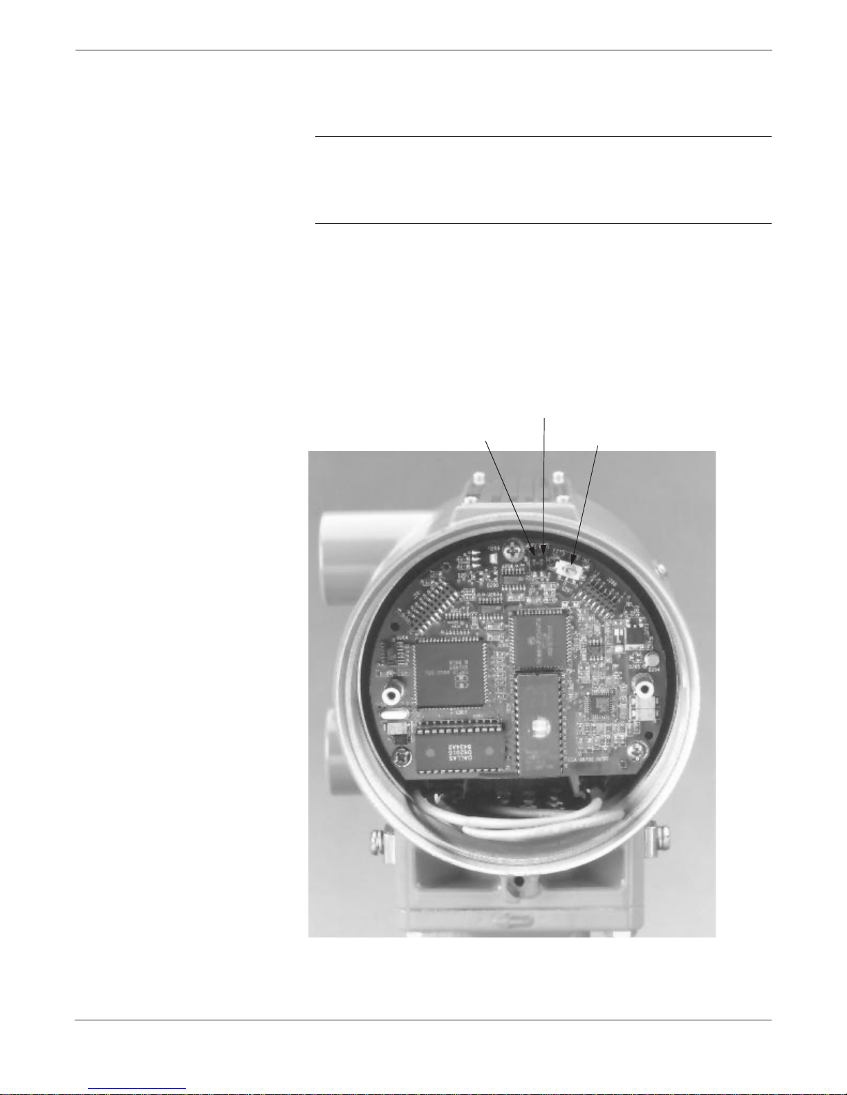
FIGURE 2-1. Model 8732C
Electronics Board and Hardware Switches.
In most cases, it is not necessary to change the setting of the hardware
switches. If you need to change the switch settings, complete the steps
outlined below:
NOTE
The hardware switches are located under the cover opposite the terminal
block. Because changing their settings requires opening the electronics
housing, make every attempt possible to carry out these procedures away
from the plant environment to protect the electronics.
1. Disconnect power to the transmitter.
2. Unscrew and remove the electronics cover.
3. Identify the location of each switch (see Figure 2-1).
4. Change the setting of the desired switches with a small screwdriver.
5. Reinstall and tighten the electronics cover.
Hi/Lo Alarm
Software Lockout
On/Off
Internal External
Analog Power
8732-004AB
2-3
Page 16
Rosemount Model 8732C Integral Mount Magnetic Flowmeter System
Mechanical Considerations
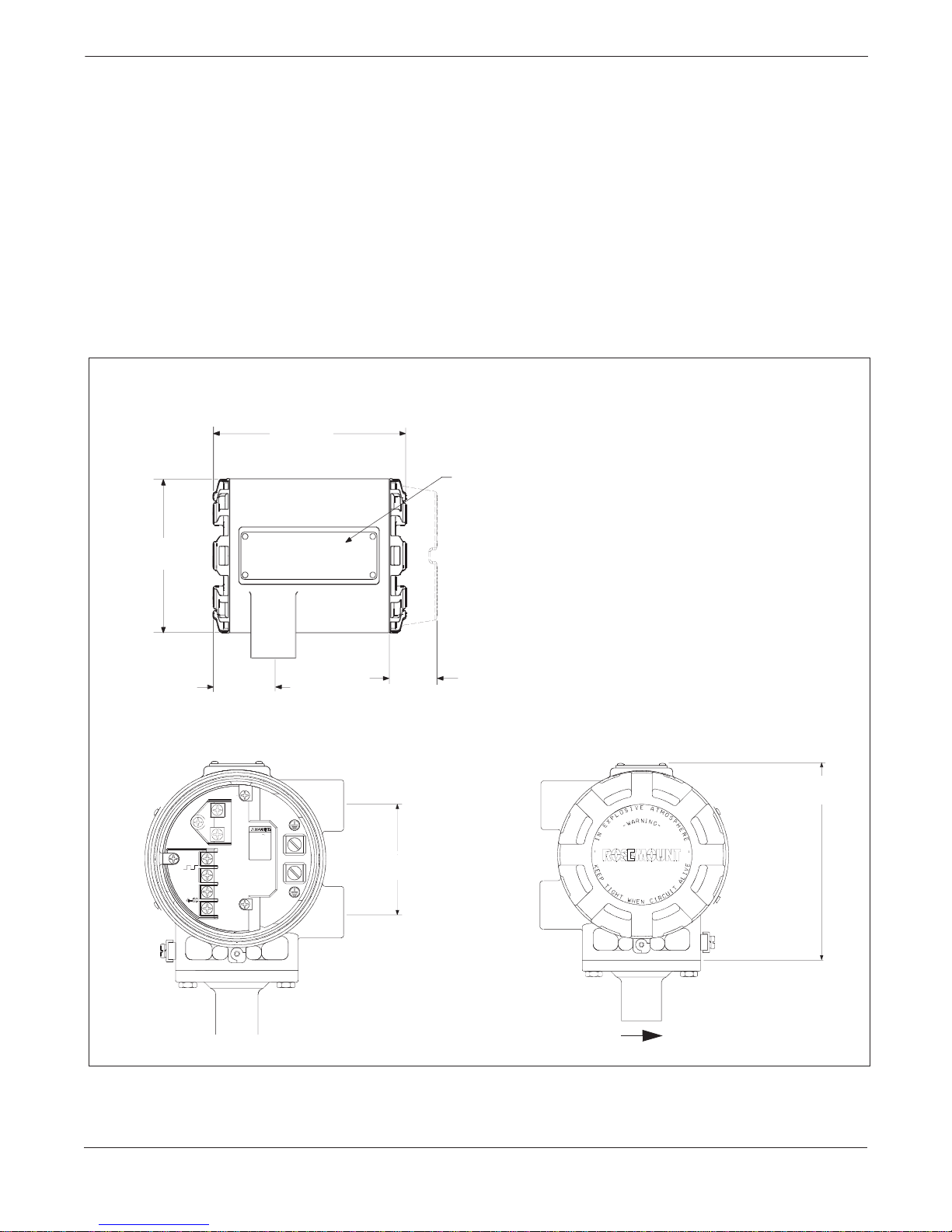
The mounting site for the Model 8732C Integral Mount Transmitter
should provide enough room for secure mounting, easy access to the
conduit ports, full opening of t he transmit ter covers, and eas y readability
of the local operator interface (LOI) screen (see Figure 2-2). The
electronics housing can be rotated on the flowtube in 90° increments.
This can be done by loosening the four mounting bolts on the bottom of
the housing, rotating the housing, and reinstalling the bolts. Be sure the
surface is clean and there is not a gap when returning the housing to its
original position.
The LOI can also b e ro tated i n 90 ° inc remen ts. Th is shou ld b e pe rf ormed
prior to installing the ma gnetic flowmeter system. Re fer to LOI Rotation
on page 3-3 for additional information.
FIGURE 2-2. Model 8732C Dimensional Drawin gs.
6.48 (165)
SST Tag
4.97
(126)
1.88
(47)
1.53
(39)
5.82
(148)
3.00
(76)
NOTE
Dimensions are in inches (millimeters).
2-4
FLOW
8732-1002A01B, 1002E01A, 1002G01A
Page 17
Installation
Electrical Considerations
Before making any electrical connections to the Model 8732C, consider
the following standards and be sure to have proper power supply,
conduit, and other accessories.
Conduit Connections The Model 8732C Integral Mount Magnetic Flowmeter Transmitter
has two ¾–inch NPT conduit connections. If one of these ports is
not being used, it must be sealed with a conduit seal. In some
cases, conduits may also require drainage if moisture could build up in
the line.
Transmitter Input Power The Model 8732C Transmitter is designed to be powered by voltages
ranging from 90 to 250 V ac (50 to 60 Hz) or 15–30 V dc. Units powered
with an ac power supply should be connected to standard ac
connections for 90 V ac or 250 V ac. Units powered by a 15–30 V dc
power supply have special considerations.
DC Power Requirements Units powered with 15–30 V dc may draw up to 2 amps of current. As a
result, the input power wire must meet certain gauge requirements.
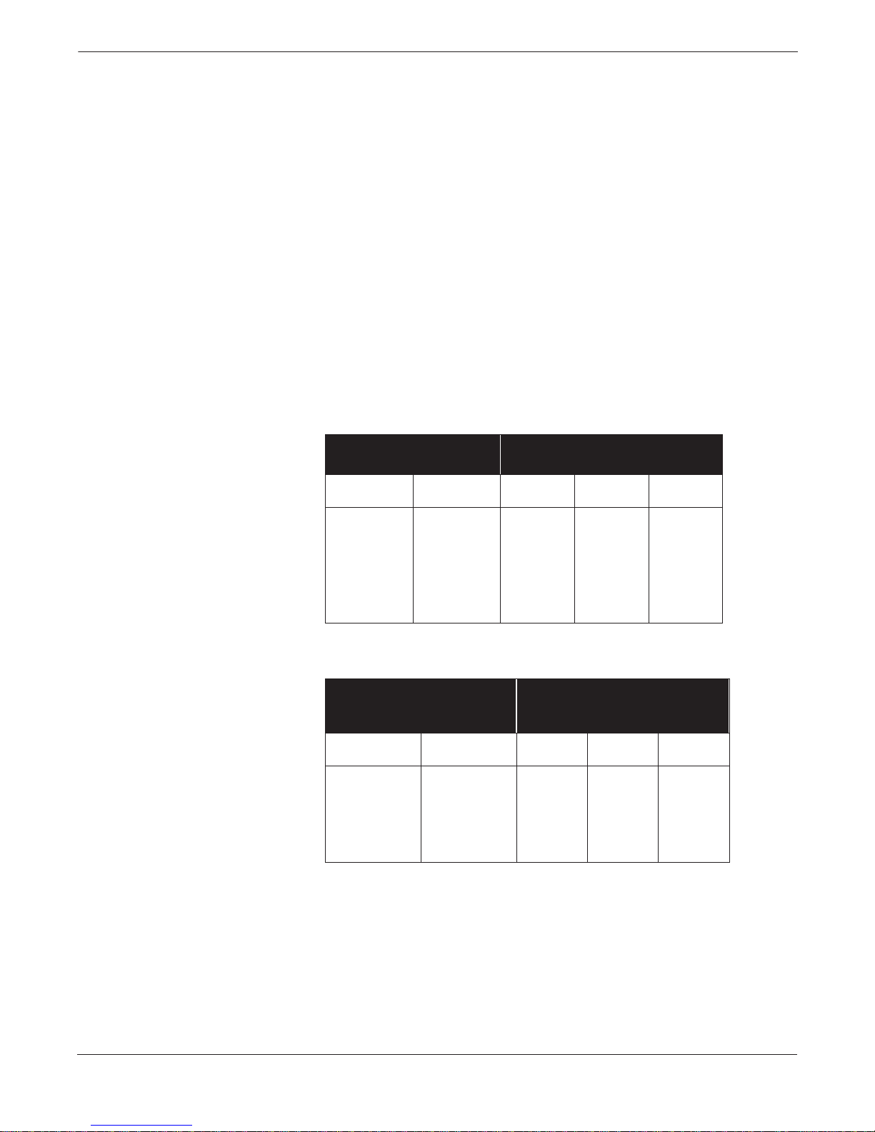
Table 2-1 and Table 2-2 show the maximum wire length for
corresponding supply voltages, wire gauges, and wire type.
TABLE 2-1. Length of Annealed
Copper Wires.
Types of
Power Supply Wires
Wire Gauge Milliohms/ft
Annealed Cu
20 10.15 1,230 625 365
18 6.385 1,955 990 585
16 4.016 3,110 1,580 930
14 2.525 4,950 2,515 1,485
12 1.588 7,870 3,995 2,360
10 0.999 12,510 6,355 3,750
Maximum Length of the Wire for Each
Corresponding Pow er Sup p ly So u rc e
30 V
Supply (ft)
24 V
Supply (ft)
20 V
Supply (ft)
TABLE 2-2. Length of Hand-drawn
Copper Wires.
Types of
Power Supply Wires
Wire Gauge Milliohms/ft
Hand-drawn Cu
18 6.640 1,880 955 565
16 4.176 2,990 1,520 895
14 2.626 4,760 2,415 1,425
12 1.652 7,565 3,840 2,270
10 1.039 12,030 6,110 3,605
Maximum Length of the Wire for
Each Corresponding Power Supply
30 V
Supply (ft)
Source
24 V
Supply (ft)
20 V
Supply (ft)
2-5
Page 18
Rosemount Model 8732C Integral Mount Magnetic Flowmeter System
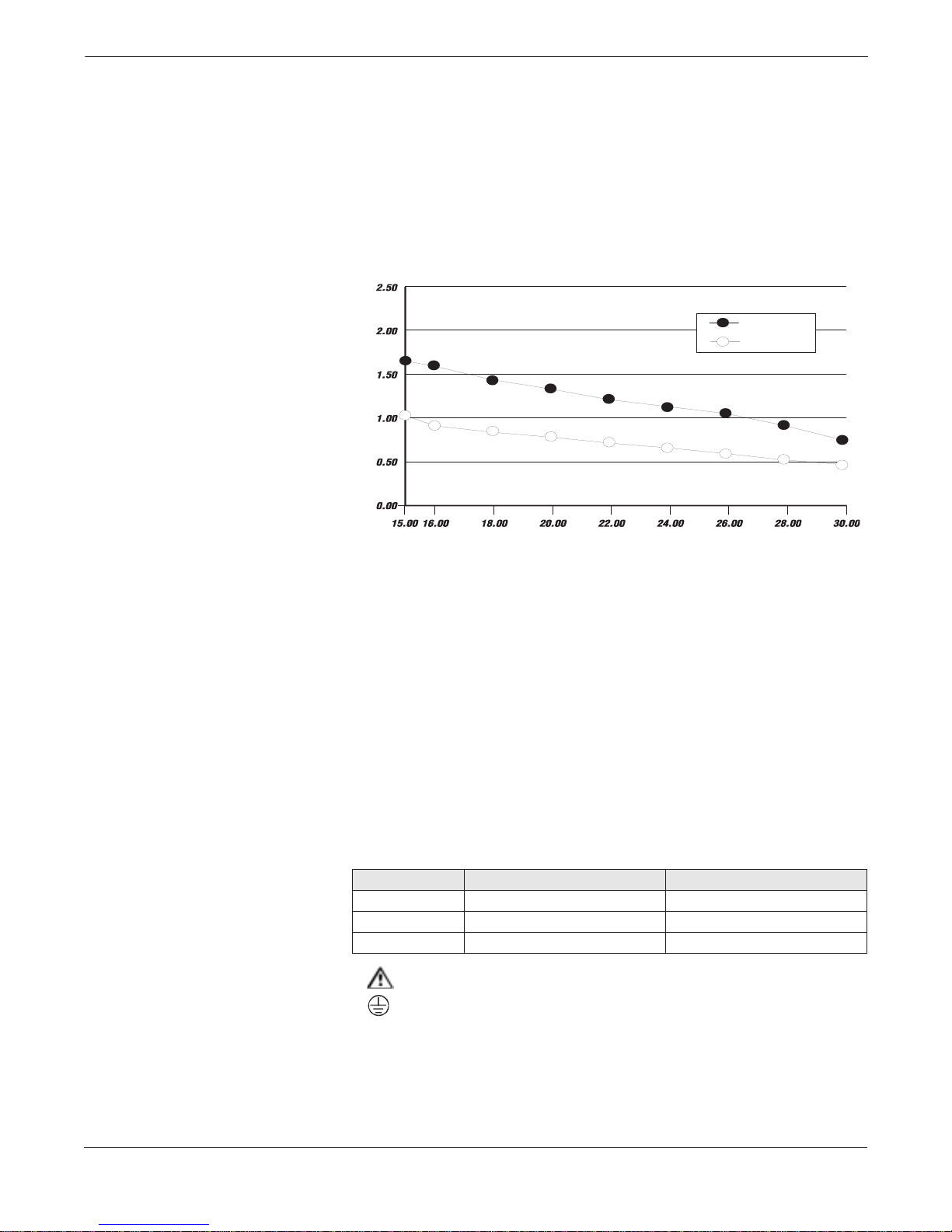
Figure 2-3 shows the surge current for each corresponding supply
voltage. For combinations not shown above, you can calculate the
maximum distance given the surge current, the voltage of the source,
and the minimum start-up voltage of the transmitter, 15 V dc using the
following equation:
Max. Resistance = (Supply Voltage –15 V dc) / Surge Current
Use Tables 2-1 and 2-2 to determine the maximum wire length
allowable for your power supply and maximum resistance.
FIGURE 2-3. Supply Current vs.
Input Voltage.
Supply Current (Amperes)
Surge
Nominal
IMPORTANT USER NOTES
Installation Category
Supply Wire Requirements
Disconnects
Overcurrent Protection
Transmitter Symbols
Input Voltage (Volts)
Installation (Overvoltage) Category II.
12- to 18-gauge wire. For connections in ambients in excess of 60° C
(140° F), use wire rated to at least 90° C (194° F).
The supply wires should be connected to the device through an external
disconnect or circuit breaker. The disconnect or circuit breaker should
be clearly labeled and located near the transmitter.
Model 8732 requires overcurrent protection of the supply lines.
Maximum rating of overcurrent devices are as follows:
Power System Fuse Rating Manufacturer
110 V ac 250 V; 1 Amp, Quick Acting Bussman AGCI or Equivalent
220 V ac 250 V;.5 Amp, Quick Acting Bussman AGCI or Equivalent
15 to 50 V dc 250 V; 3 Amp; Quick Acting Bussman AGCI or Equivalent
Caution Symbol — Check product documentation for details.
Protective conductor (grounding) terminal.
2-6
Page 19

Installation
Environmental
Considerations
INSTALLATION
PROCEDURES
Handling
To ensure maximum transmitter life, avoid excessive heat and
vibration. Typical problem areas include high-vibration lines with
integrally mounted transmitters, warm-climate installations in direct
sunlight, and outdoor installations in cold climates.
Because the Model 8732C System requires external power, access to a
suitable power source must be ensured.
Overheating will damage the flowtube. Do not encapsulate the flowtube
with heating elements.
These installation tasks provide detailed mechanical and electrical
installation procedures.
All parts should be handled carefully to prevent damage. Whenever
possible, transport the system to the installation site in the original
shipping containers. The flowtube is shipped with end covers to protect
it from mechanical damage and normal unrestrained distortion. End
covers should not be removed until just before installation. Keep
shipping plugs in conduit connections until conduits are connected
and sealed.
All flowtube liners are vulnerable to handling damage. Never place
anything through the flowtube for the purpose of lifting or gaining
leverage. Liner damage can render the flowtube useless.
FIGURE 2-4. Model 8705
Flowtube Support for Handling.
Flanged flowtubes have different lifting and transportation guidance.
Refer to Figure 2-4 for correct handling techniques. Wafer style
flowtubes have no special lifting directions, however every precaution
should be taken to avoid liner damage.
½- to 4-Inch Flowtubes
6-Inch and
Larger Flowtubes
8732-0281B02A, C02A
2-7
Page 20
Rosemount Model 8732C Integral Mount Magnetic Flowmeter System
Flowtube Mounting
Physical mounting of a flowtube is similar to installing a typical section
of pipe. Only conventional tools, equipment, and accessories (such as
bolts, gaskets, and grounding hardware) are required.
Calibration Rosemount magnetic flowmeter systems are wet-calibrated at the
factory and need no further calibration during installation.
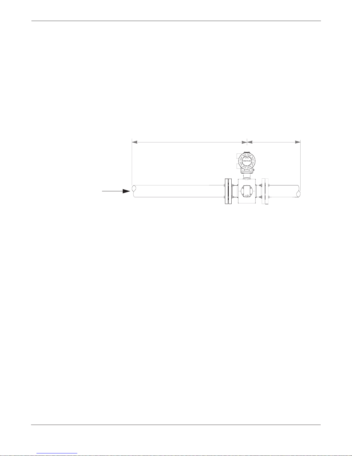
Upstream/Downstream Piping To ensure specific accuracy over widely varying process conditions,
install the flowtube with a minimum of five straight pipe diameters
upstream and two pipe diameters downstream from the electrode
plane, as shown in Figure 2-5. This flowtube placement is usually
adequate to allow for disturbances created by elbows, valves,
and reducers.
FIGURE 2-5. Upstream and
Downstream Straight Pipe Diameter.
5 Pipe Diameters 2 Pipe Diameters
Flow
8732-0281G01A
2-8
Page 21
Installation
Flowtube Orientation
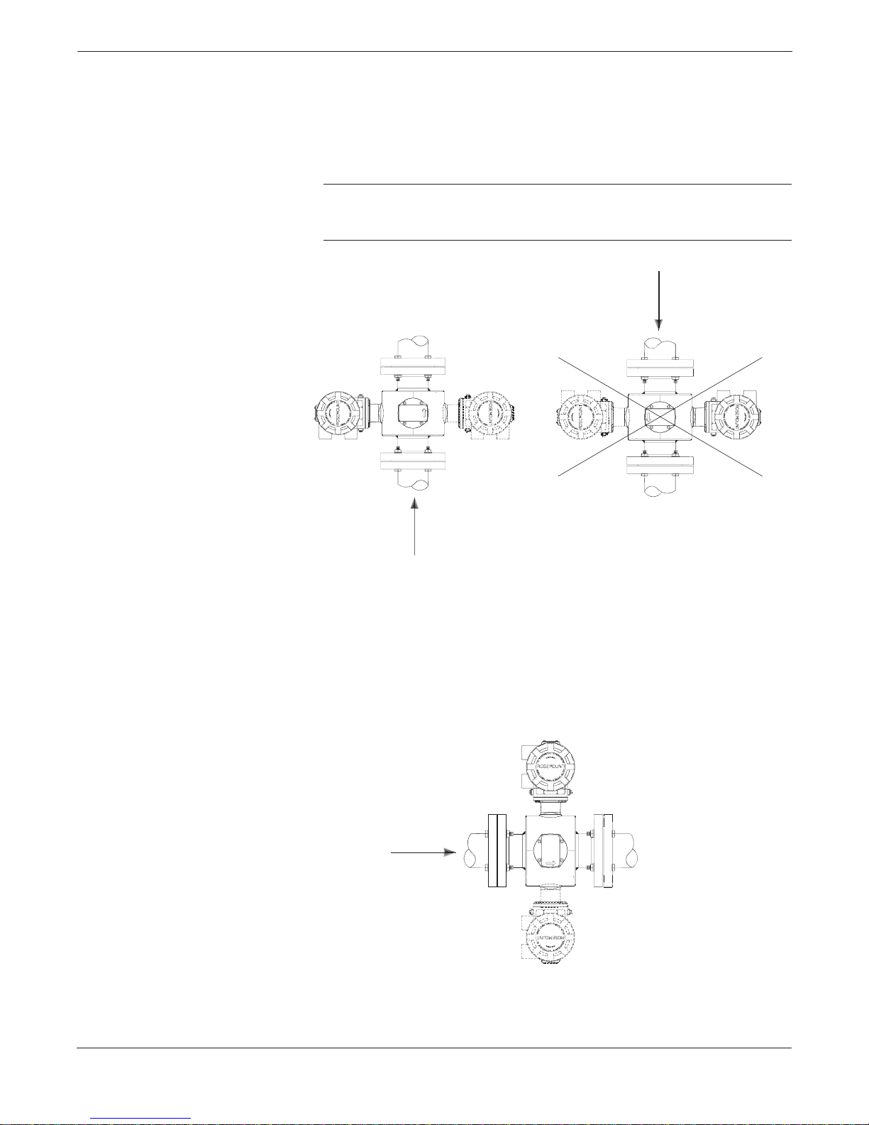
Vertical Installation Vertical installation allows upward process fluid flow and is generally
preferred. Upward flow keeps the cross-sectional area full, regardless
of flow rate. Orientation of the electrode plane is unimportant in
vertical installations.
NOTE
As shown in Figure 2-6, avoid downward vertical flows where back
pressure is inadequate to ensure that the flowtube remains full.
FIGURE 2-6. Vertical Flowtube Orientation.
Flow
Flow
B
Horizontal Installation Horizontal installation should be restricted to low piping sections that
are normally full. Orient the electrode plane to within 45 degrees of
horizontal in horizontal installations. A deviation of more than 45
degrees of horizontal would place an electrode at or near the top of the
flowtube–making it more susceptible to insulation by air or entrapped
gas at the top of the flowtube.
FIGURE 2-7. Horizontal Flowtube Orientation.
Flow
8705-0005A01A, 0005A01B
8705-0005A01C
2-9
Page 22
Rosemount Model 8732C Integral Mount Magnetic Flowmeter System
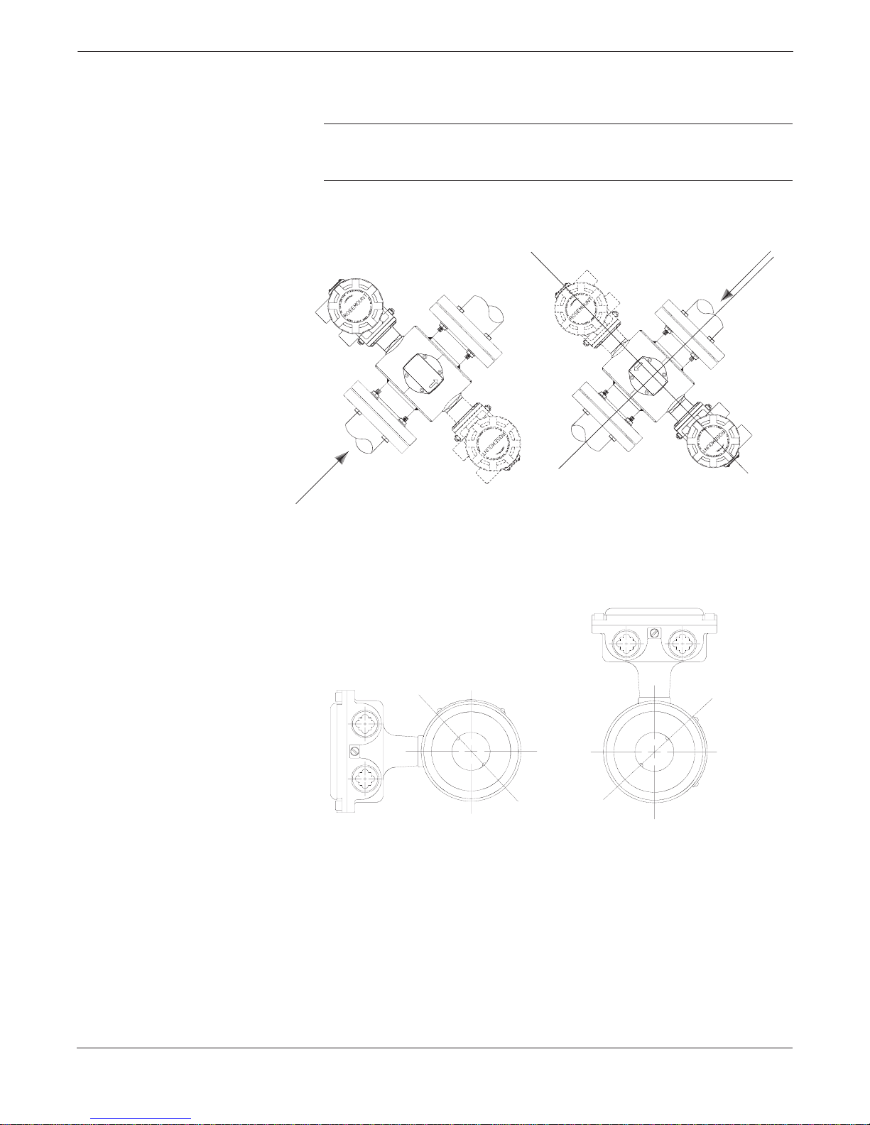
An inclined installation, as shown in Figure 2-8, is an acceptable
installation technique. This tends to keep the cross-sectional area full.
NOTE
As shown in Figure 2-8, avoid declining installations where back
pressure is inadequate to ensure that the flowtube remains full.
FIGURE 2-8. Incline or Decline Orientation.
Flow
Flow
B
8705-0005A01E, 0005A01F
The electrodes in the Model 8711 are properly oriented when the top
of the flowtube is either vertical or horizontal, as shown in Figure .
Avoid any mounting orientation that positions the top of the flowtube
at 45° from the vertical or horizontal position.
Model 8711 Mounting Position.
2-10
45° Electrode Plane
8711-8711E01A, 8711F01A
45° Electrode Plane
Page 23
Installation
Flow Direction
FIGURE 2-9. Flow Direction.
Gaskets
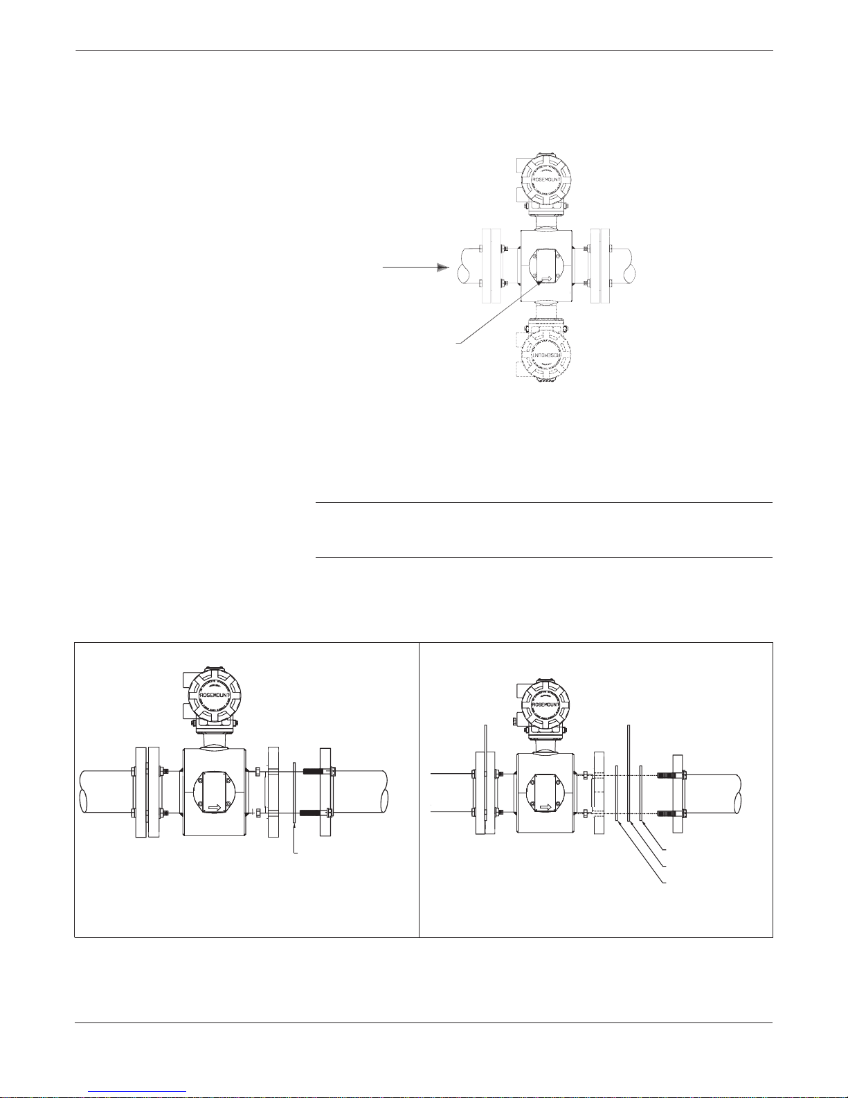
The flowtube should be mounted so that the FORWARD end of the flow
arrow, shown on the flowtube identification tag, points in the direction
of flow through the tube (see Figure 2-9).
Flow
Flow Direction Arrow
8705-0005G01A
The flowtube requires gaskets at each of its connections to adjacent
equipment or piping. The gasket material selected must be compatible
with the process fluid and operating conditions, and must not damage
the liner.
FIGURE 2-10. Model 8705 Flange Gaskets.
Gasket
FLANGE GASKETS FOR ALL OTHER
FLOWTUBES
NOTE
To avoid possible flowtube damage, do not use metallic or spiral
wound gaskets.
BA
Gasket
Grounding Ring
Gasket
FLANGE GASKETS WITH NON-ATTACHED
GROUNDING RINGS
8732-0040F, 0038F
2-11
Page 24
Rosemount Model 8732C Integral Mount Magnetic Flowmeter System
Flange Bolts
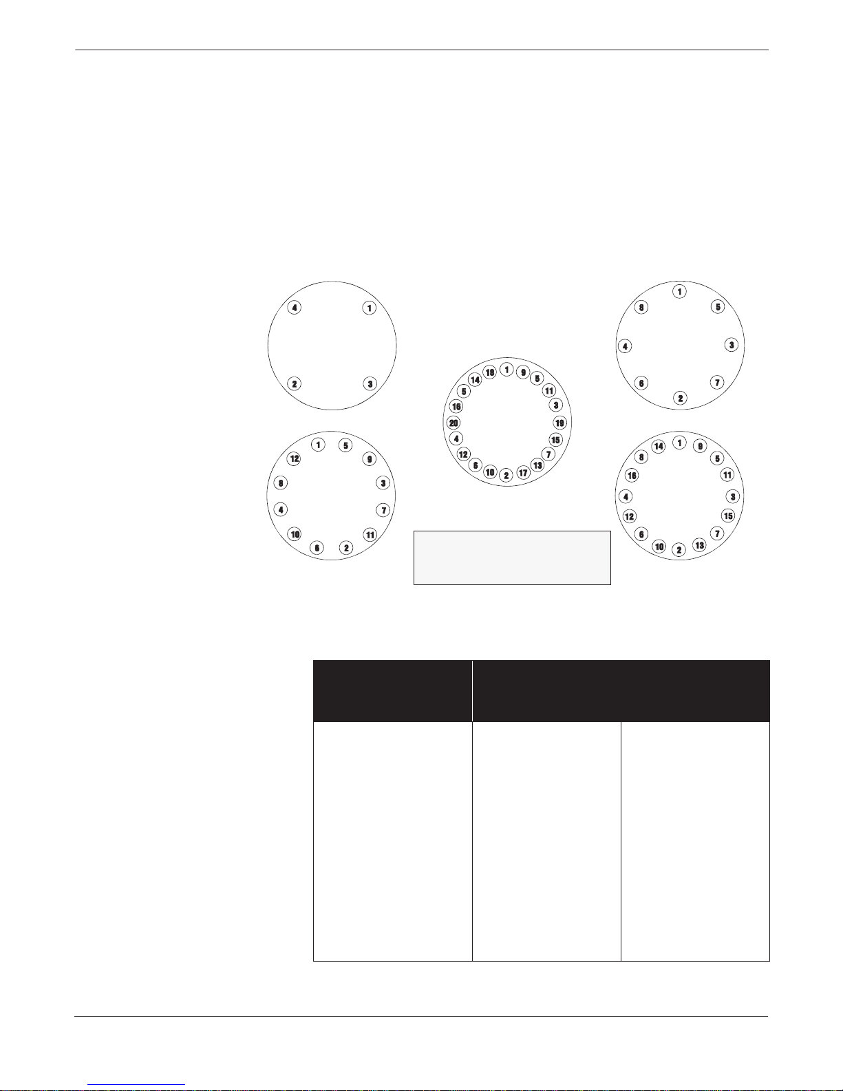
Flowtube sizes and torque values for Class 150 and Class 300 flanges
are listed in T able 2-3. Tighten flange bolts in the incremental sequence
shown in Figure 2-11.
Model 8705 Correct flange bolt tightening is crucial for proper flowtube operation and
life. All bolts must be tightened in the proper sequence to the specified
torque limits. Failure to observe these instructions could result in severe
damage to the flowtube lining and possible flowtube replacement.
Always check for leaks after tightening flange bolts. All flowtubes
require a second torquing 24 hours after initial flange bolt tightening.
FIGURE 2-11. Model 8705 Flange
Bolt Torquing Sequence.
4-Bolt
8-Bolt
TABLE 2-3. Model 8705 Flange Bolt
Torque Specifications.
12-Bolt
Nominal
Flowtube
Size (inches)
½
1
1½
2
3
4
6
8
10
12
14
16
18
20
24
30
36
20-Bolt
Torque the flange bolts
in increments according to
the above numerical sequence.
Flange Bolt Torque
Specifications in Foot-Pounds
Class 150 Flange Class 300 Flange
10
10
17
25
45
35
60
80
70
80
100
90
125
125
150
150
200
14-Bolt
8701-0589A
10
10
22
17
35
50
65
60
65
80
—
—
—
—
—
—
—
2-12
Page 25
Installation
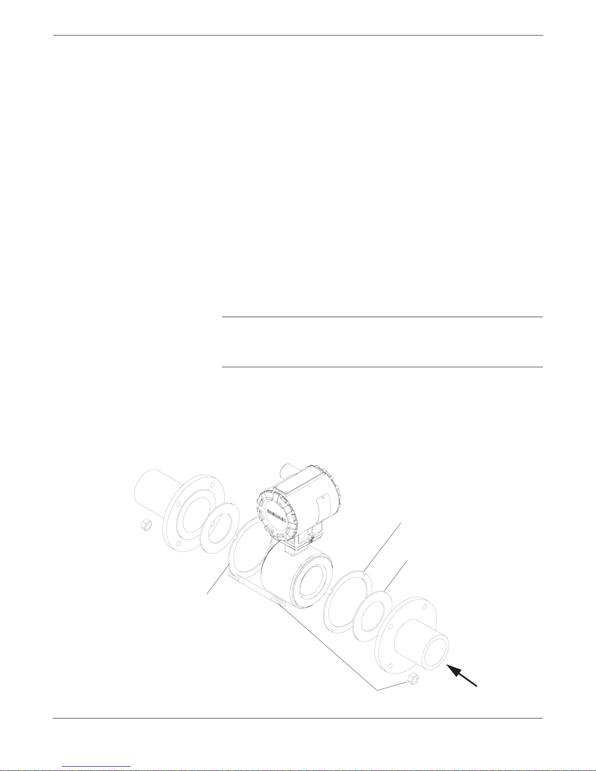
Model 8711 For Model 8711, the flowtube inside diameter should be centered with
respect to the inside diameter of the adjoining upstream and
downstream piping. This will ensure the flowmeter achieves its
specified accuracy. Mounting bolts supplied with 0.15 through 1-inch
(4–25 mm) line sizes are specifically sized to properly align these
flowtubes with the flange configurations specified. For 1.5 through
8-inch (40–200 mm) line sizes, two centering rings are supplied for
alignment purposes. Place the centering rings over the flowtube using
the following instructions as a reference. If you received two centering
sleeves, follow the steps described under Alignment with
Centering Sleeves.
Alignment with Centering Rings
1. Insert the two studs for the bottom side of the flowtube between
the pipe flanges.
2. Place the two centering rings over each end of the flowtube.
3. Place the flowtube between the flanges. Make sure that the
centering rings are properly placed in the studs. The
studs should be aligned with the markings on the rings that
correspond to the flange you are using.
4. Insert the remaining studs, and install the washers and nuts.
5. Tighten the nuts to the specifications listed in Table 2-4.
NOTE
On the 4- and 6-inch PN 10–16, the installer will need to insert the
flowtube with rings first and then insert the studs. The slots on this
ring scenario are located on the inside of the ring.
FIGURE 2-12. Alignment with Centering Rings.
Centering Ring
Centering Ring
Gasket for Tefzel/Teflon-lined
Flowtubes only
(Supplied by Customer)
Installation Stud s, Nut s, an d Washers
FLOW
2-13
Page 26
Rosemount Model 8732C Integral Mount Magnetic Flowmeter System
Alignment with Centering Sleeves
Follow the instructions below for the 1.5- through 8-inch
(40 to 200 mm) line sizes if you received two centering
sleeves instead of centering rings:
1. Insert the two studs for the bottom side of the flowtube,
with the centering sleeves, between the pipe flanges.
2. Place the flowtube firmly against the two centering sleeves,
between the flanges.
3. Insert the remaining studs.
4. Install the washers and nuts.
5. Tighten the nuts to the specifications listed in Table 2-4.
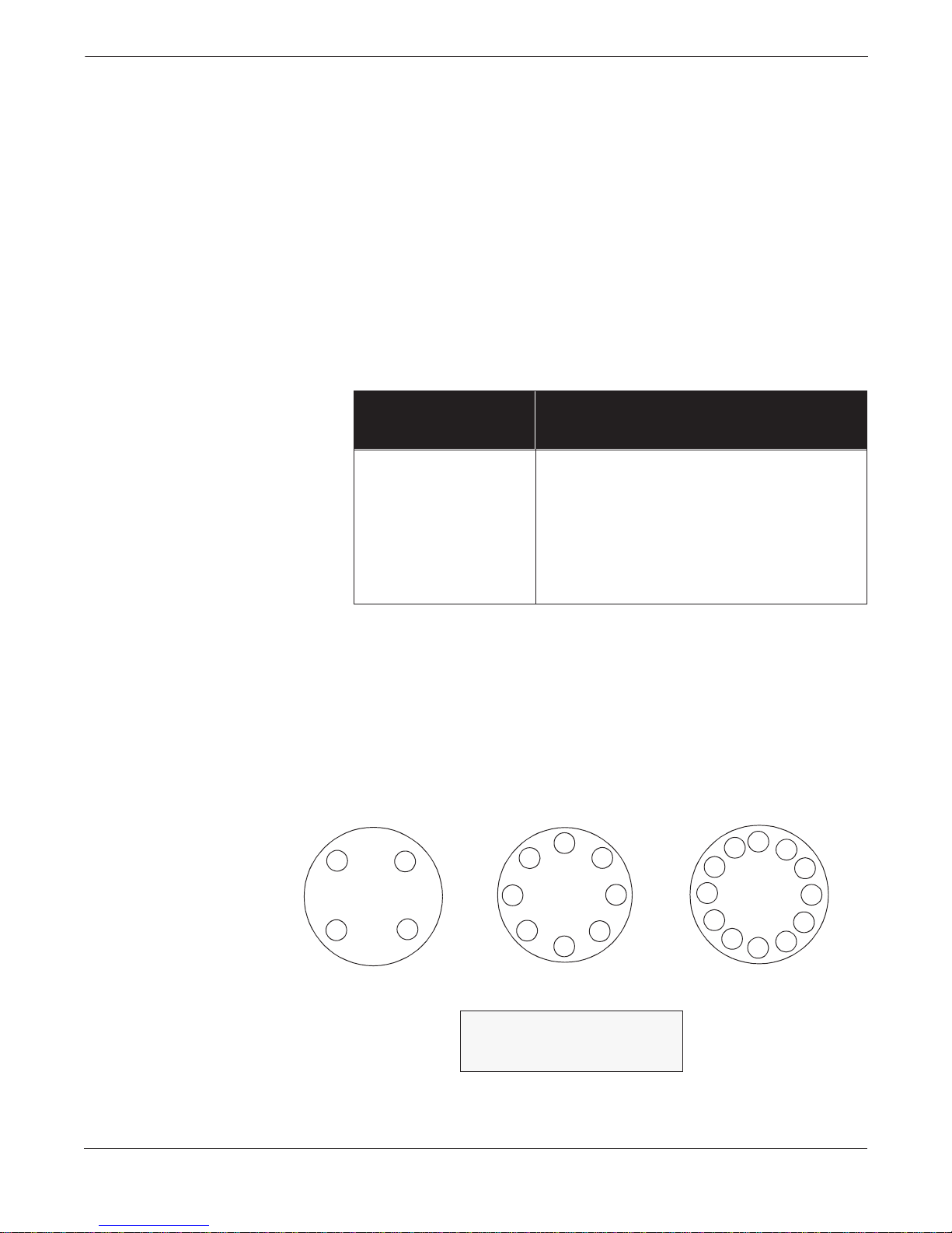
TABLE 2-4. Flange Bolt
Torque Specifications.
Nominal Flowtube Size,
Inches (mm)
0.15 (4)
0.30 (8)
0.50 (15)
1 (25)
1.50 (40)
2 (50)
3 (80)
4 (100)
6 (150)
8 (200)
Applicable for Both Class 150 and 300 Flanges
Specifications in Foot-Pounds
Bolt Torque
5
5
5
10
15
25
40
30
50
70
FIGURE 2-13. Model 871 1 Flange
Bolt Torquing Sequences.
2-14
1
1
4
4-Bolt 8-Bolt 12-Bolt
3
2
the above numerical sequence.
8
4
6
Torque the flange bolts
in increments according to
5
3
7
2
12
8
4
10
6
1
5
9
3
7
11
2
Page 27
Installation
Grounding
Grounding the flowtube is one of the most important details of flowtube
installation. Proper grounding ensures that only the voltage induced in
the flowtubes magnetic field is measured.
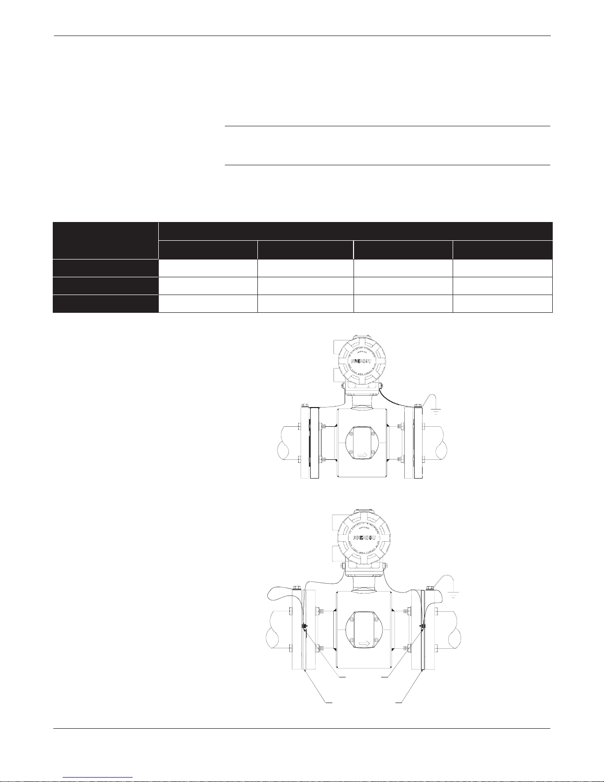
Model 8705 Use Table 2-5 to determin e which grounding option figure to use for
proper installation.
NOTE
Consult factory for installations requiring cathodic protection or
situations where high currents or high potential exist in the process.
TABLE 2-5. Model 8705 Grounding Installation.
Grounding Options
Type of Pipe
Conductive Unlined Pipe See Figure 2-14 Not Required Not Required See Figure 2-15
Conductive Lined Pipe Insufficient Grounding See Figure 2-16 See Figure 2-14 See Figure 2-15
Non-conductive Pipe Insufficient Grounding See Figure 2-18 See Figure 2-19 See Figure 2-17
FIGURE 2-14. Model 8705 Grounding
for Conductive Unlined Pipe and
Grounding for Conductive Lin ed Pipe
with Grounding Electrodes.
No Grounding Opt ions Grounding Rings Grounding Electrode s Lining Protectors
FIGURE 2-15. Model 8705 Gro unding for
Conductive Unlined Pipe with Lining
Protectors and Grou nding for Con ductive
Lined Pipe with Lining Protectors.
Lining
Protector Tab
Lining
Protectors
Earth
Ground
0281A02A
Earth
Ground
8732-0281J02A
2-15
Page 28

Rosemount Model 8732C Integral Mount Magnetic Flowmeter System
FIGURE 2-16. Model 8705
Grounding for Conductive Lined
Pipe with Grounding Rings.
Earth
Ground
FIGURE 2-17. Model 8705
Grounding for Non-Conductiv e
Pipe with Lining Protectors.
FIGURE 2-18. Model 8705
Grounding for Non-Conductive
Pipe with Grounding Rings.
Grounding Rings
Lining
Protector Tab
Lining
Protectors
8732C-0281F02A
Earth
Ground
8732-00281K02A
2-16
Grounding Rings
Earth
Ground
8732-0281L02A
Page 29

Installation
FIGURE 2-19. Model 8705
Grounding for Non-Conducti ve
Pipe with Grounding Electrodes.
Model 8711 Use Table 2-6 to help determine the grounding option required for
proper operation.
TABLE 2-6. Model 8711
Grounding Installation.
Grounding Options
8732-0281M02A
Type of Pipe
Conductive Unlined Pipe
Conductive Lined Pipe
Non-conductive Pipe
FIGURE 2-20. Model 8711
Grounding for Conductive Unlined Pipe
and Grounding for Conductive Lined
Pipe with Groundin g Ele ct rode s.
No Grounding Opt ions Grounding Rings Grounding Electrode s
See Figure 2-20 Not Required Not Required
Insufficient Grounding See Figure 2-21 See Figure 2-20
Insufficient Grounding See Figure 2-22 See Figure 2-23
Earth
Ground
8711-0360A01C
2-17
Page 30
Rosemount Model 8732C Integral Mount Magnetic Flowmeter System
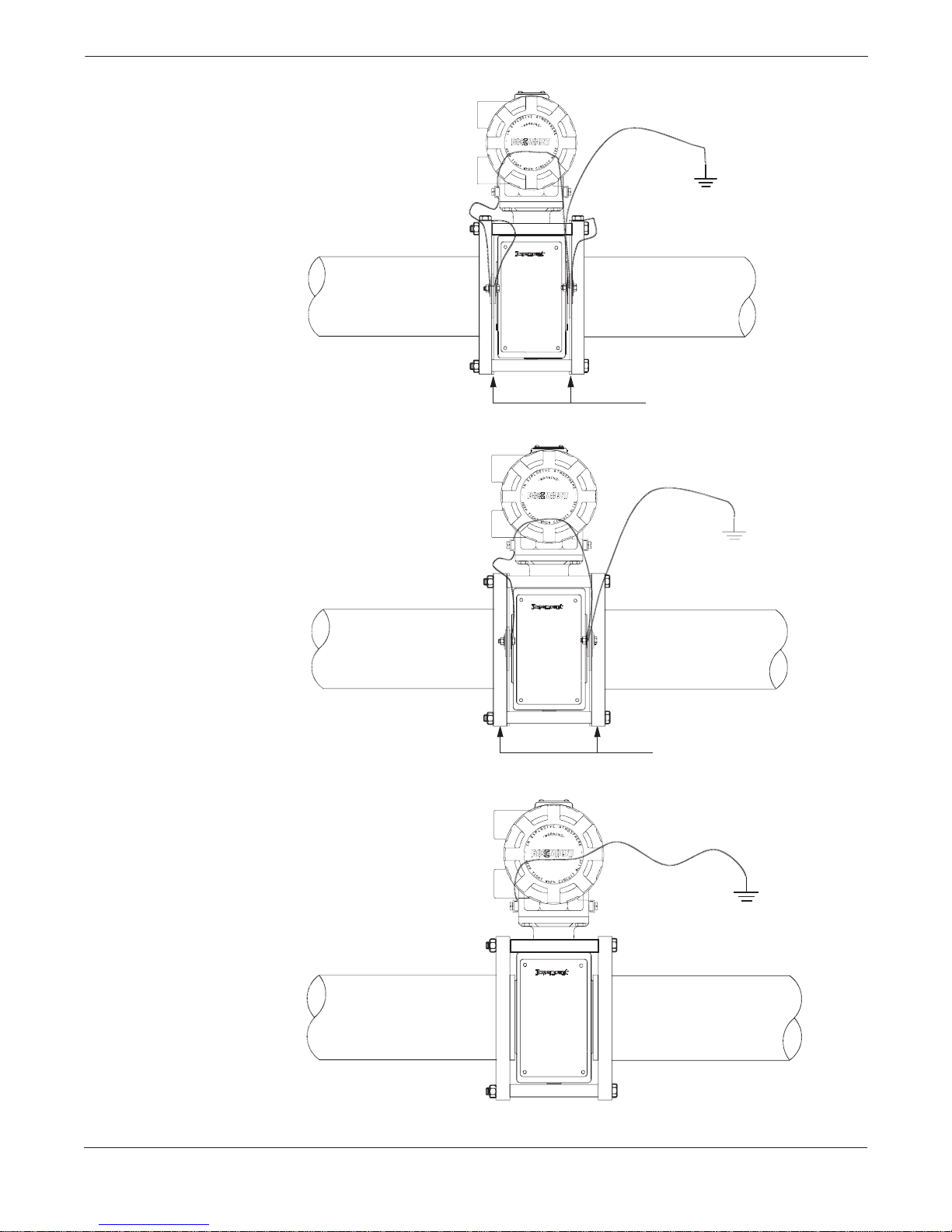
FIGURE 2-21. Model 8711
Grounding for Conductive Lined
Pipe with Grounding Rings.
Earth
Ground
FIGURE 2-22. Model 8711
Grounding for Non-Conductiv e
Pipe with Grounding Rings.
FIGURE 2-23. Model 8711
Grounding for Non-Conductive
Pipe with Grounding Electrodes.
Grounding Rin gs
Grounding Rings
8711-03660A01D
Earth
Ground
8711-03660a01B
2-18
Earth
Ground
8711-0368A01A
Page 31
Installation
Install Conduit
Power Connections
Transmitter junction boxes have ports for ¾-inch NPT
conduit connections.
1. Connect the ¾-inch NPT conduit to the transmitter in accordance
with local or plant electrical codes.
2. Seal unused ports to prevent moisture or other contaminat ion
from entering the junction box.
Do not overtighten metal plugs used to seal wiring compartment ports;
overtightening can damage the housing.
To connect power to the transmitter, complete the following steps:
1. Ensure that the power source and connecting cable meet the
requirements outlined in Transmitter Input Power on page 2-5.
2. Turn off the power source.
3. Open the power terminal cover.
4. Run the power cable through the conduit to the transmitter.
5. Loosen the terminal cable guard for the input power terminals
L1 and N or +dc and -dc.
6. Connect the power cable leads as follows:
For an ac-powered transmitter:
• Connect ac Ground to a grounding lug.
• Connect ac Neutral to terminal N.
• Connect ac Line to terminal L1.
For a dc-powered transmitter:
• Connect dc Ground to a grounding lug.
• Connect + dc.
• Connect – dc.
The dc-powered transmitter has a different terminal block and differen t
electronics that are not compatible with an ac-powered transmitter.
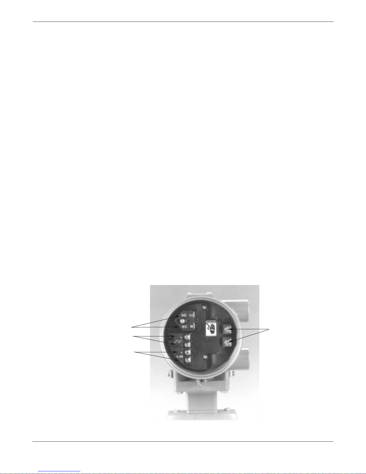
FIGURE 2-24. Power Connections.
Input Powe r
90–250 V ac
or 15–30 V dc
Digital Outputs
Grounding
Lugs
4–20 mA
Outputs
8732-005AB
2-19
Page 32
Rosemount Model 8732C Integral Mount Magnetic Flowmeter System
OPTIONS,
CONSIDERATIONS,
AND PROCEDURES
Connect 4–20 mA Loop
External Power Source
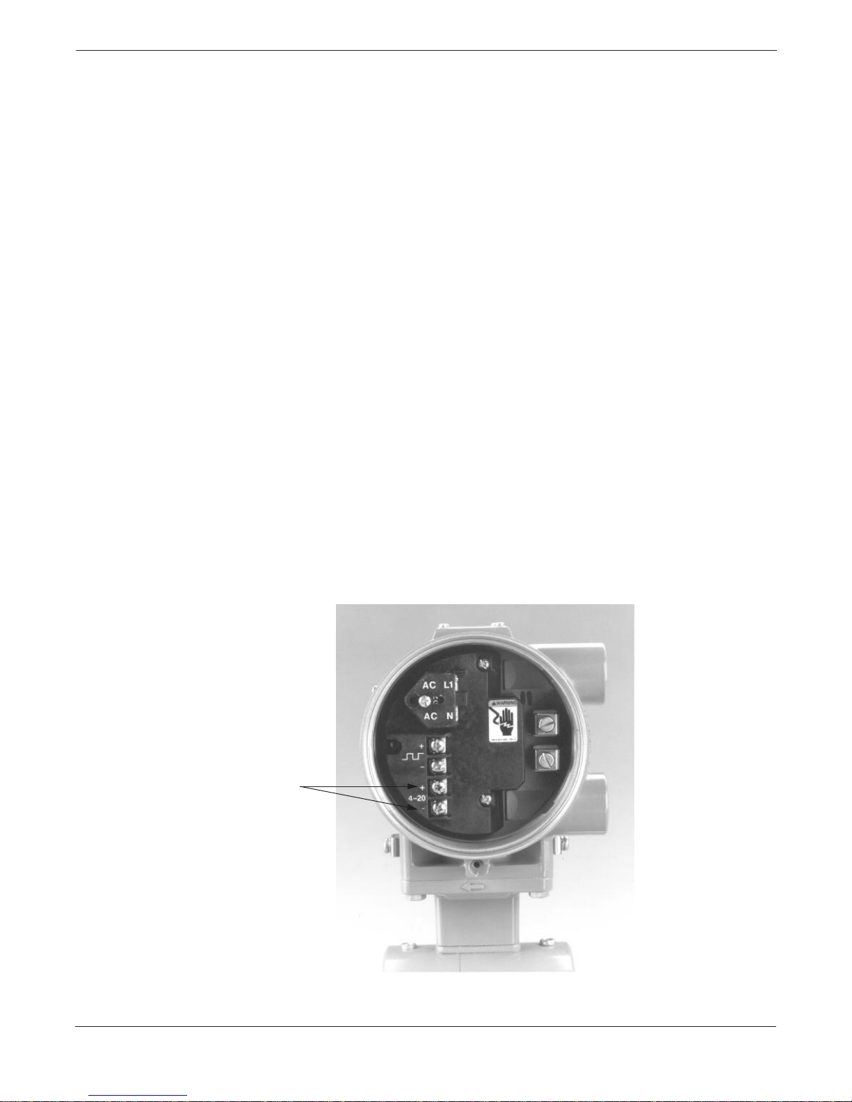
FIGURE 2-25. 4–20 mA
Loop Power Connections.
If your application of the Model 8732C includes an externally powered
4–20 mA loop, auxiliary output control or pulse output, certain
requirements may apply in addition to those previously listed.
Satisfy these requirements before attempting to install and operate
the Model 8732C.
The 4–20 mA output loop is powered either internally or externally.
Internal
The loop may be powered from the transmitter itself. Resistance in the
loop must be 1,000 ohms or less. If a HART-based communicator or a
distributed control system (DCS) is used, it must be connected across a
minimum of 250 ohms resistance in the loop.
External
External power must be supplied if the Model 8732C is to be used in a
multidrop installation (see Multidrop Communications on page
4-18). A 10–30 V dc power source is required. If a HART-based
Communicator or DCS is used, it must be connected across a
minimum of 250 ohms resistance in the loop.
If your application uses the external power option for the 4–20 mA
loop, complete the following steps to connect the power source to
the transmitter:
1. Ensure that the power source and connecting cable meet the
requirements outlined above and in Electrical Considerations
on page 2-5.
2. Turn off the transmitter and analog loop power sources.
3. Run the power cable into the transmitter.
4. Connect – dc to terminal – 4–20 mA.
5. Connect + dc to terminal + 4–20 mA.
4–20 mA
Outputs
2-20
8732-005AB
Page 33
Installation
Connect Pulse Output
Power Source
The Pulse Output function provides an isolated switch-closure
frequency output signal that is proportional to the flow through the
flowtube. The signal is normally used in conjunction with an external
totalizer or control system. The following requirements apply:
Supply Voltage: Up to 24 V ac or dc.
Load Resistance: 100 to 100 k ohms (typical
' 1 k).
Pulse Duration: 0.5 to 100 msec (adjustable).
Maximum Power: 5.75 watts.
Switch Closure: Bi-directional MOFSET.
If your application uses the pulse output option, complete the following
steps to connect the power source to the transmitter:
1. Ensure that the power source and connecting cable meet the
requirements outlined above.
2. Turn off the transmitter and pulse output power sources.
3. Run the power cable into the transmitter.
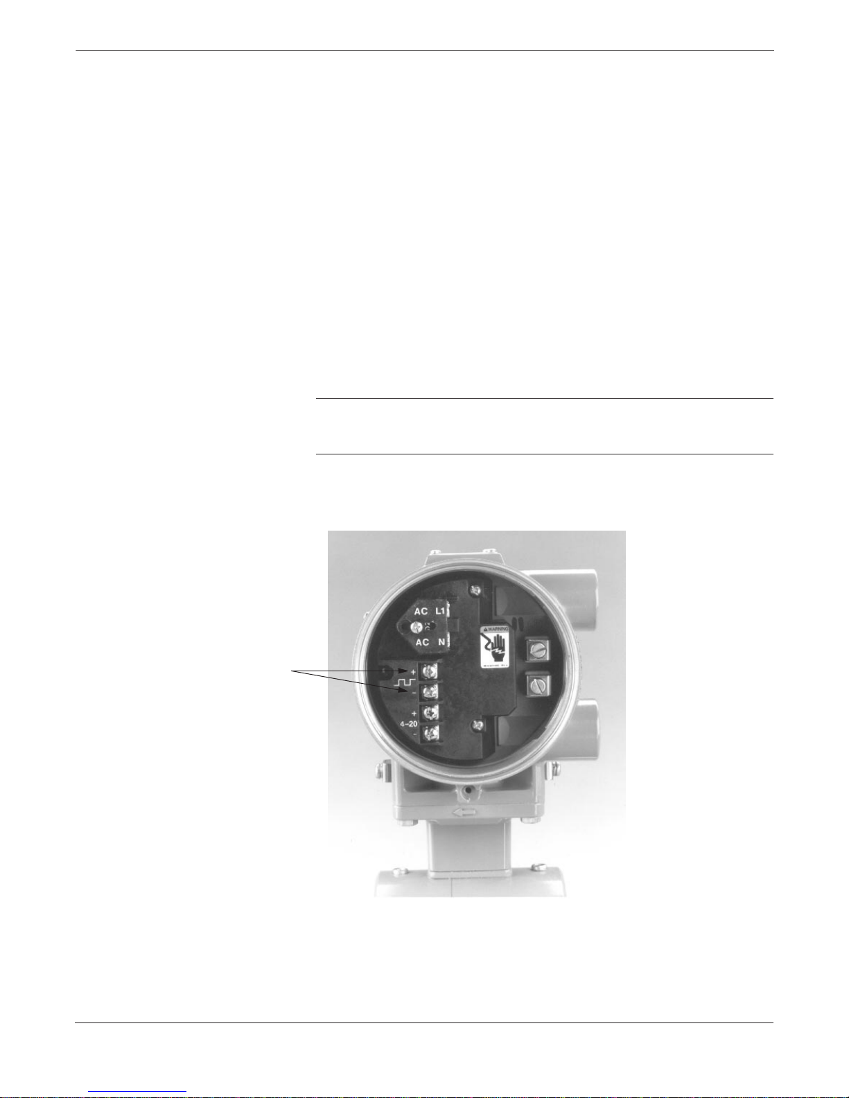
4. Connect the two wires that convey switch closure information
to the + and – terminals.
NOTE
If dc power is used, it is preferre d to conne ct – dc to terminal – and + dc
to terminal +.
FIGURE 2-26. Pulse or
Digital Output Connections.
Digital Outputs
8732-005AB
2-21
Page 34

Rosemount Model 8732C Integral Mount Magnetic Flowmeter System
Connect Auxiliary
Output Control
In lieu of pulse output, the auxiliary output control function allows you
to externally signal a zero flow or reverse flow condition. The following
requirements apply:
Supply Voltage: Up to 24 V ac or dc.
Load Resistance: 100 to 100 k ohms (typical
Pulse Duration: 0.5 to 100 msec (adjustable).
Maximum Power: 5.75 watts.
Switch Closure: Bi-directional MOFSET.
If your application uses auxiliary output control, complete the following
steps to connect the power source to the transmitter:
1. Ensure that the power source and connecting cable meet the
requirements outlined above.
2. Turn off the transmitter and pulse output power sources.
3. Run the power cable into the transmitter.
4. Connect the two wires that convey switch closure information to
the positive and negative terminals.
NOTE
If dc power is used, it is preferre d to conne ct – dc to terminal – and + dc
to terminal +.
' 1 k).
QUICK START-UP
Once the magnetic flowmeter system is installed and communication is
established, final configuration of the transmitter must be completed.
You may perform these functions with the LOI (Section 3: Local
Operator Interface) or HART Communicator (Appendix A: HART
Communicator). Specific instructions regarding these functions are
provided in Section 4: Transmitter Functions.
To initiate a basic flowmeter system start-up, only two parameters
are required:
1. Set Units
2. Analog Output Range
If your application of the magnetic flowmeter system involves more
advanced functions such as multidrop or pulse output, additional
configuration steps may be required to enable full functionality. See
Section 4: Transmitter Functions.
2-22
Page 35

Installation
Installation Check
and Guide
Use this guide to check new installations of Rosemount Magnetic
Flowmeter Systems that appear to malfunction. For detailed
troubleshooting instructions, see Section 5: Troubleshooting.
Before You Begin
Be sure that power to your system is off before beginning these checks.
Transmitter
1. Check for correct flowtube calibration number entered in
the software. (The calibration number is listed on the
flowtube nameplate.)
2. Check for correct flowtube line size entered in the software.
(The line size value is listed on the flowtube nameplate.)
3. Check that the analog range of the transmitter matches the
analog range in the control system.
4. Check that the forced analog output of the transmitter produces
the correct output at the control system.
Flowtube
1. For horizontal flow installations, ensure that the electrodes are in
a plane such that they remain covered by process fluid.
2. For vertical or inclined installations, ensure that process fluid is
flowing up into the flowtube to keep the electrodes covered by
process fluid.
3. Ensure that the grounding straps on the flowtube are connected
to grounding rings, lining protectors, or the adjacent pipe flanges.
Improper grounding will cause erratic operation of the system.
Process Fluid
1. Process fluid conductivity should be 5
centimeter, minimum.
2. Process fluid must be free of air and gasses.
3. Flowtube should be full of process fluid.
µmhos per
PROCESS LEAK
PROTECTION
(MODEL 8705 ONLY)
The Model 8705 Flowtube housing is fabricated from carbon steel
to perform two separate functions in the flowtube design. First, it
provides shielding for the flowtube magnetics so that external
disturbances cannot interfere with the magnetic field and thus affect
the flow measurement.
Second, it provides the physical protection to the coils and other
internal components from contamination and physical damage that
might occur in the industrial environment. The housing is completely
welded, and the joints contain no gaskets; the totally leak-free
enclosure protects the internal components, even in the most
demanding installations.
2-23
Page 36
Rosemount Model 8732C Integral Mount Magnetic Flowmeter System
Process Leak
Containment
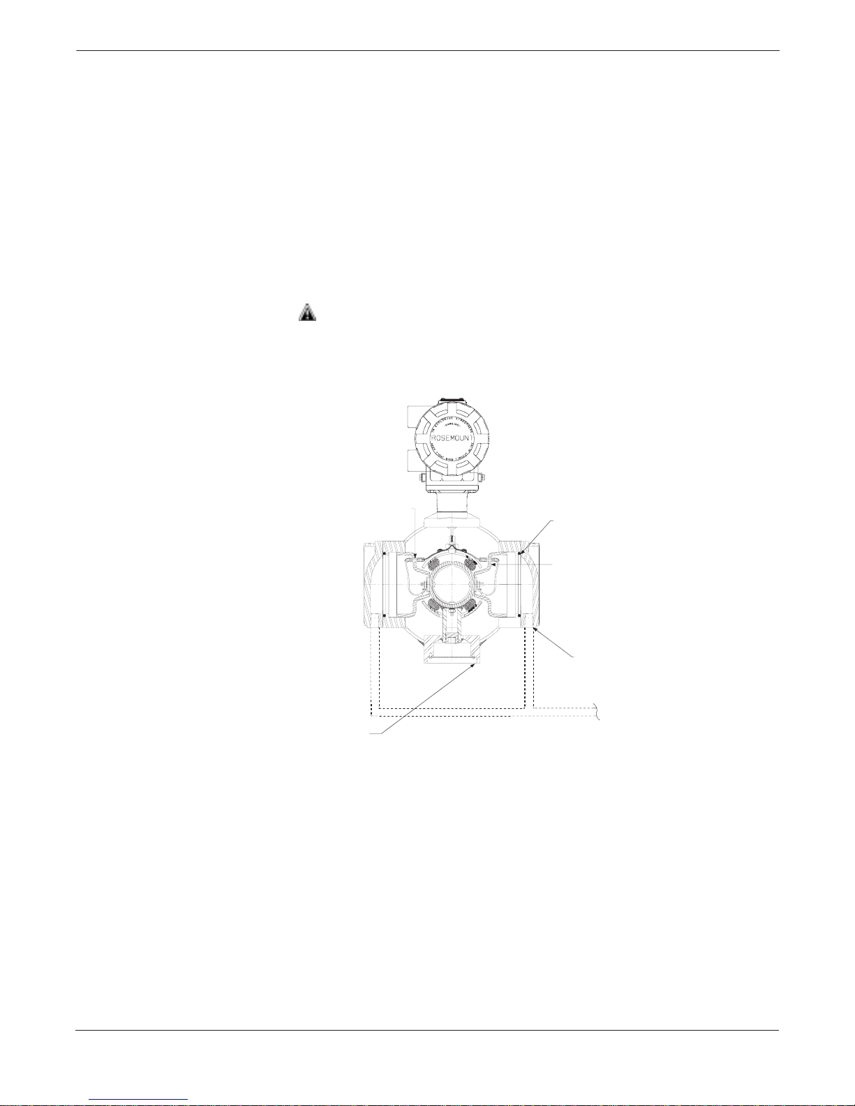
FIGURE 2-27. Sealed Electrode
Compartment–Standard Configuration.
As shown in Figure 2-27, the standard configuration divides the
housing into three separate compartments: one for each electrode and
one for the coils. The electrodes are separated from the rest of the
internal components and the coils.
If a damaged liner allows process fluid to migrate behind the electrode
seals, the fluid is contained in the electrode compartment. The sealed
electrode compartment prevents the process fluid from entering the coil
compartment where it would damage the coils and other internal
components.
The electrode compartments are designed to contain the process fluid at
full line pressure. An O-ring sealed cover provides access to each of the
electrode compartments from outside the flowtube; drainports are
provided in each cover for the removal of fluid.
The electrode compartment could contain full line pressure and it must
be depressurized before the cover is removed. Removing the cover
before depressurizing may result in death or serious injury.
Fused Glass
Ground Electrode Port
If it is necessary to capture any process fluid leaka ge for fugit ive emission
control, connect the appropriate piping to the drainports and provide for
proper disposal as shown in Figure 2-27.
The second configuration uses a completely welded coil housing but does
not provide the separate electrode compartment or external electrode
access of the standard construction. This housing configuration is
identified by a “W1” in the option code of the model number.
Seal
O-ring Seal
Sealed Electrode
Compartment
¼–18 NPT
Optional:
Use drain port to plumb
to a safe area
8705-0007ADGC
2-24
Page 37
Installation
Relief Valves
FIGURE 2-28. Relief Valve Venting.
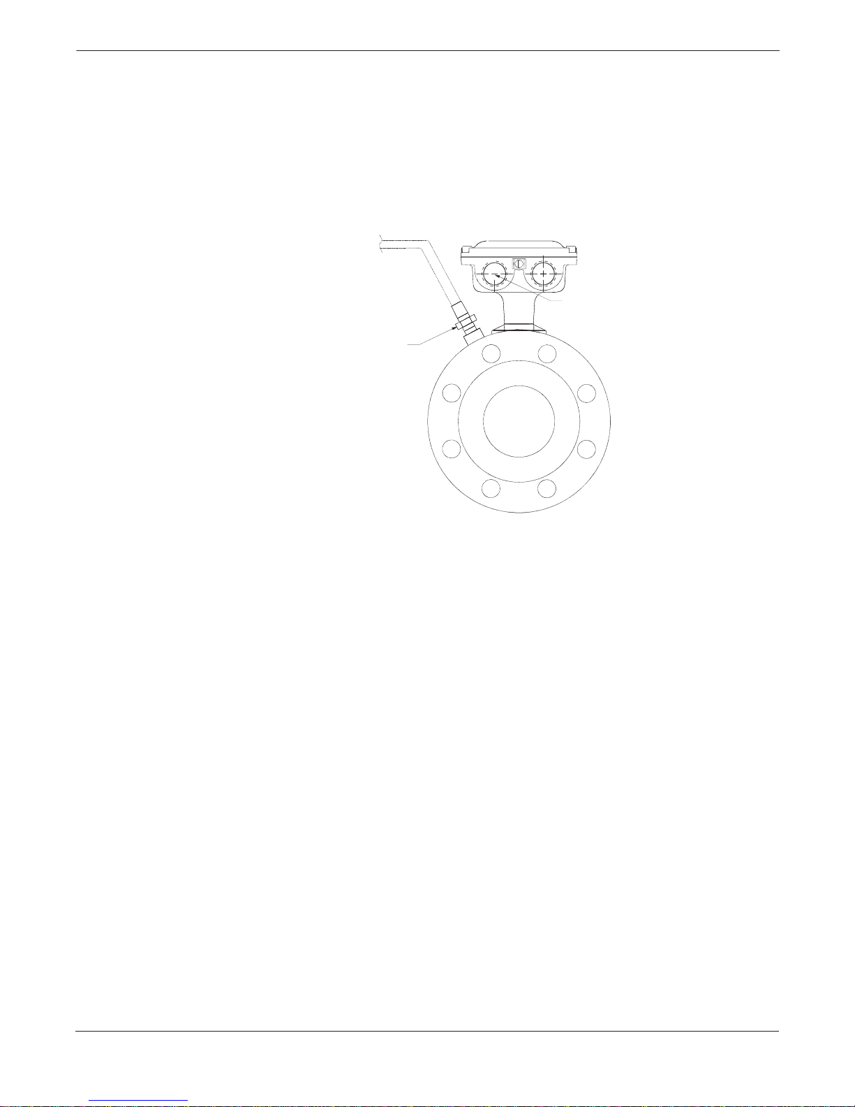
Housing configuration “W1” provides a relief valve in the housing to
prevent possible overpressuring caused by damage to the lining or
other situations that might allow process pressure to enter the housing.
The relief valve will vent when the pressure inside the flowtube
housing exceeds 5 psi. Additional piping (provided by the user) may be
connected to this relief valve to drain any process leakage to safe
containment (see Figure 2-28). In the event of a process leak, these
models will not protect the coils or other sensitive areas of the
flowtube from exposure to the pressure fluid.
Optional:
Plumb to an area consistent
with the type of process
¾–14 NPT Conduit
Connection
¼ NPT
8705-0021A05B
2-25
Page 38

Rosemount Model 8732C Integral Mount Magnetic Flowmeter System
Field-Removable
Electrodes
The field-removable electrode option allows the user to remove the
electrode assembly with the flowtube still mounted in the line.
Frequently, this option will be used for cleaning the electrode head
when coating is of concern.
The flowtube should be drained of any process fluid prior to disassembly of
electrodes. Care should be taken when handling products, or electrodes
having been in contact with products of a corrosive nature, to avoid
per so n al i nj u ry. Take care to avoid rotating the electrode whe n removing
it to avoid leakage. Some resistance may be experienced due to the
tight o-ring fit.
Remove the Electrode Assembly
Use the following procedure to remove the electrode assembly
from the flowtube.
1. Loosen and remove the screws that secure the electrode cover.
2. Remove the electrode cover and o-rings. It is generally
recommended that new o-rings be installed upon reassembly.
3. Loosen and remove the screw that secures the signal wire
to the electrode.
4. Remove the retaining nut.
5. Take the electrode from the electrode housing by pulling it out,
with firm pressure, along the axis of the electrode.
Replace the Electrode Assembly
Use the following procedure to replace the electrode assembly
into the flowtube.
1. Lubricate the o-rings.
2. Install the o-rings on the electrode.
3. Insert the electrode assembly into the electrode housing.
4. Secure the electrode into the housing with the retaining nut.
Tighten the retaining nut to 15 in/oz of torque.
5. Secure the signal wire to the electrode with a screw.
6. Install the o-rings into the electrode cover.
7. Secure the electrode cover to the flowtube with the screws.
2-26
Page 39

Installation
2-27
Page 40

Rosemount Model 8732C Integral Mount Magnetic Flowmeter System
2-28
Page 41
Section
3 Local Operator Interface
THE LOCAL OPERATOR
INTERFACE (LOI)
SAFETY MESSAGES
The LOI option is an operator communications center for the Model
8732C. Through the LOI, the operator can access any transmitter
function for changing configuration parameter settings, checking
totalized values, or other functions.
Instructions and procedures in this section may require special
precautions to ensure the safety of the personnel performing the
operations. Information that raises potential safety issues is indicated
by a warning symbol ( ). Please refer to the following safety messages
before performing an operation preceded by this symbol.
Explosions could result in death or serious injury:
• Verify that the operating atmosphere of the flowtube and transmitter is
consistent with the appropriate hazardous locations certifications.
• Do not remove the transmitter cover in explosive atmospheres
when the circuit is alive.
• Both transmitter covers must be fully engaged to meet
explosion-proof requirements.
Failure to follow safe installation and servicing guidelines could result in
death or serious injury:
• Make sure only qualified personnel perform these procedures.
• Do not perform any service other than those contained in this manual
unless qualified.
High voltage that may be present on leads co uld cause electri cal sh ock :
• Avoid contact with leads and terminals.
3-1
Page 42
Rosemount Model 8732C Integral Mount Magnetic Flowmeter System
LOI Features
FIGURE 3-1. Model 8732C
Local Operator Interface.
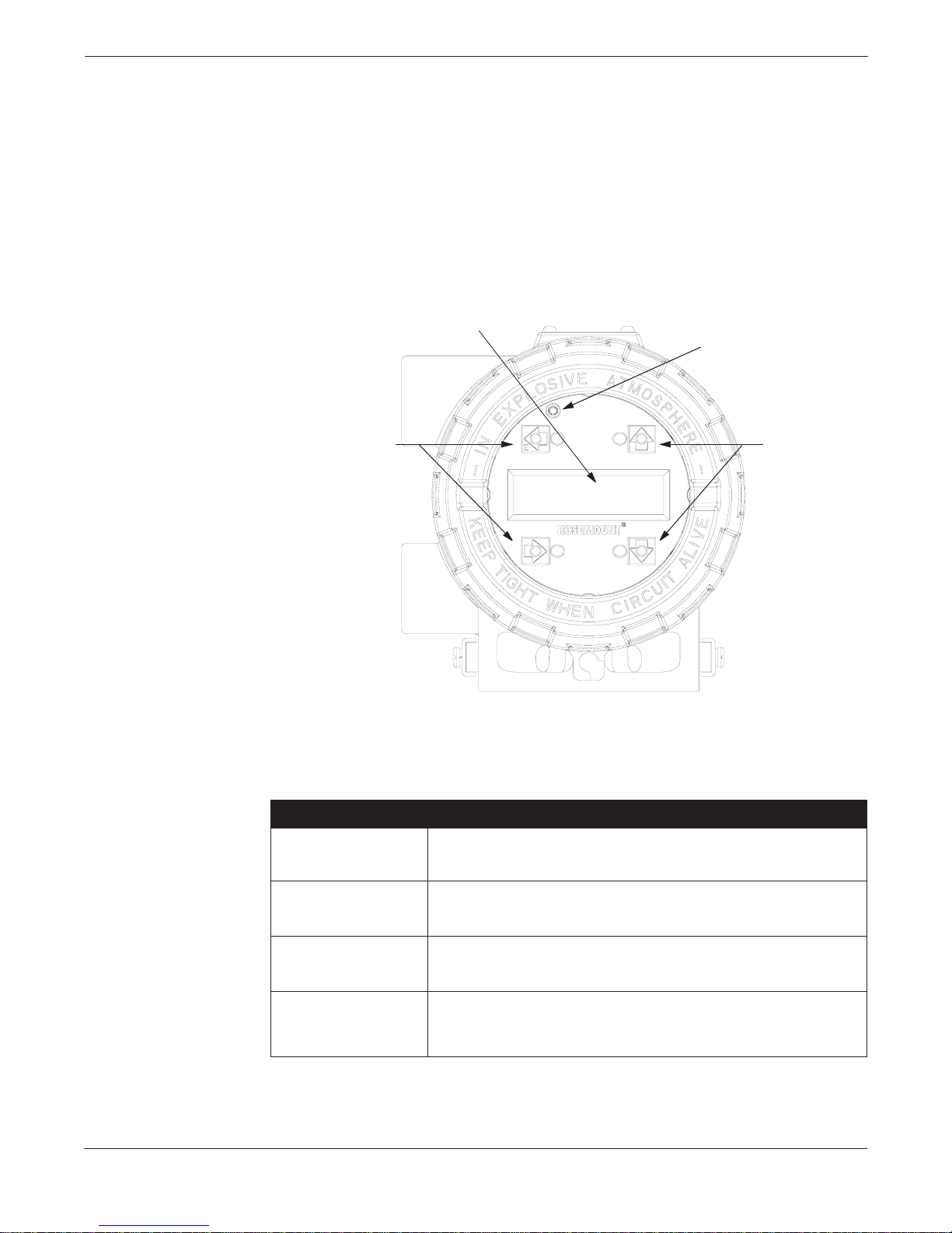
The LOI option contains a two-line, 16-character liquid crystal display
(LCD) that is back-lit and visible from any angle. This display uses
optical switches that reliably detect the touch of a finger on the LOI
glass. Because the switches are completely enclosed, they will not be
affected by the process environment.
A red light emitting diode (LED) on the display illuminates whenever
an optical switch is activated providing positive operator feedback and
guarding against accidental configuration changes. Table 3-1 lists and
details the functions of the LOI keys.
Liquid Crystal Display
Transmitter
Parameter Keys
Key Press Indicator
Transmitter
Parameter Keys
TABLE 3-1. LOI Keys and Functions.
LOI Key Function Performed
Enter. Moves to the previous display field. Starts the totalizin g fun ctio n if it is
E ←
↑
↓
→
stopped, and stops the function if it is running.
Moves the cursor to the next higher field. Changes user-selected variables in a field
to next higher value. Changes parameters on a predefined list.
Moves the cursor to the next lower field. Changes user-selected variables in a field
to next lower value. Changes parameters on a predefined list.
Enters a specific field on the LOI. Moves cursor to next user-selected variable.
Changes paramet ers o n a predef ine d list. Aborts a cho sen ope rat ion . St ops th e
totalizing display (totalizing function continues to run). Resets the net totalizing
display after the displa y is stop pe d.
8732-0031A01A
3-2
Page 43

Local Operator Interface
LOI Rotation
Each magnetic flowmeter installation is different from application to
application; therefore, the LOI display can be rotated to accommodate
various setups using the following procedure:
1. Remove power from the transmitter.
2. Unscrew and remove the LOI cover. Do not remove the cover in
explosive atmospheres when the circuit is alive.
3. Unfasten the 2 screws that attach the LOI assembly to the main
circuit assembly.
4. Carefully remove the LOI assembly by pulling it away from
the transmitter.
5. Remove the pin assembly from the back of the LOI.
6. Insert the short end of the pin assembly into the circuit board
connector J201. Ensure that all pins are engaged.
7. Position the LOI in a preferred 90° rotation and carefully press
LOI into the pin assembly.
NOTE
Misalignment may cause permanent pin damage.
8. Fasten the two screws that attach the LOI to the main
circuit assembly.
9. Replace the LOI cover.
Data Entry
The LOI keypad has no numerical keys. Enter numerical data using the
following procedure:
1. Access the appropriate function.
2. Use
3. Use
4. Use
5. Press
→ to highlight the digit you want to enter or change.
↑ or ↓ to change the highlighted value.
For numerical data,
decimal point, dash, and blank.
For alphabetical data, they toggle through the letters of the
alphabet A–Z, digits 0–9, and the symbols &, +, –, *, /, $, @, %,
and the blank space.
↑ or ↓ is al so used to toggle thro ugh pre -determined choices that
(
do not require data entry.)
↑ or ↓ toggles through the digits 0–9,
→ to highlight and change other digits you want to change.
E← when the desired choice is displayed on the screen.
3-3
Page 44

Rosemount Model 8732C Integral Mount Magnetic Flowmeter System
LOI EXAMPLES
Table Value
Example
Select Value
Example
Use the Transmitter Parameter keys shown in Figure 3-1 to change the
parameters. The parameters are set in one of two ways: Table Value
and Select Value.
Table Values
Parameters that are available from a predefined list, such as units.
Select Values
Parameters that consist of a user-created number or character string, such as a
calibration number. Values are entered one character at a time using the data
entry keys.
Setting the TUBE SIZE:
1. Access the tube size through basic setup.
2. Press
3. When you reach the desired size, press
4. Set the loop to manual if necessary, and press
After a moment, the LCD will display the new tube size and the
maximum flow rate.
Changing the UPPER RANGE VALUE (URV):
1. Access the URV through basic setup.
2. Press
3. Press
4. Repeat steps 2 and 3 until the desired number is displayed.
5. Press
↑ or ↓ to increment the tube size to the next value.
E←.
E← again.
→ to position the cursor.
↑ or ↓ to set the number.
E←.
3-4
Page 45
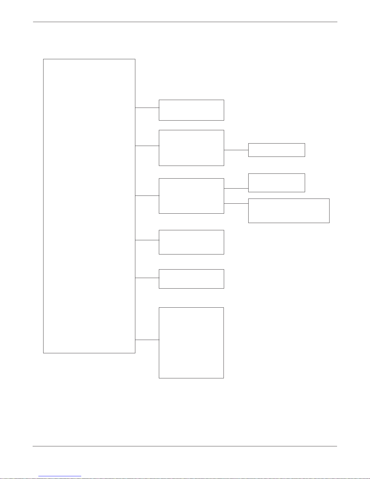
LOI SCREEN FLOW
Local Operator Interface
↑ →
DISPLAY
TOTALIZER
DISPLAY SETUP
BASIC SETUP
DETAILED SETUP
TRANSMITTER
TEST
↑ Flow Rate Display
↓ Totalize Display
Display Lock
↑ →Units
Tube Size
Tube Cal. No.
URV, LRV
Damping
↓ End of List
↑ →Lo-Flow Cutoff
Dig Out Config
Special Units
Coil Frequency
Sig Processing
↓ End of List
↑ →Xmtr. Test
Loop Test
Pulse Test
↓ End of List
↑ →URV Configure
↓ LRV Confi g u re
↑ →Dig Out Select
Pulse Output
↓ Aux Output
↑ →Sig Processing Control
Sig Processing Samples
Sig Processing Max% Limit
↓ Sig Processing Time Limit
TRANSMITTER
TRIM
DEVICE
↓
INFORMATION
↑ →4–20 mA Trim
Auto Zero
Gain Trim
↑ →Error Messages
Xmtr. Tag
Xmtr. S/N
Software Rev.
Description
Messages
Flowtube Tag
Flowtube S/N
Liner Material
Electrode Type
Electrode Material
Flange Type
↓ Flange Material
3-5
Page 46
Rosemount Model 8732C Integral Mount Magnetic Flowmeter System
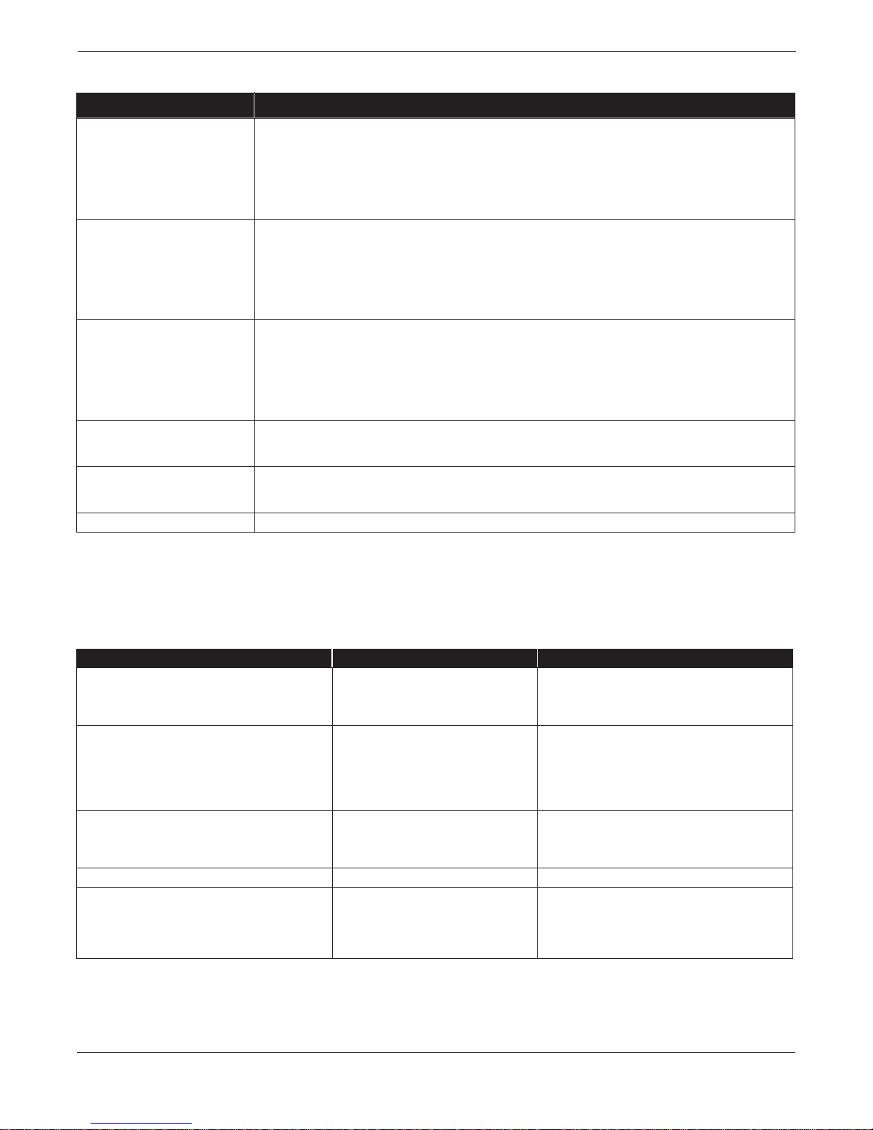
TABLE 3-2. LOI Display and Functions.
LOI Display Transmitter Function
Display Setup Display Lock ................... Locks out configuration changes (including totalizer start/stop/reset) from being made
Flow Rate Display........... User-selected settings for transmitter flow indication:
Totalize Display ............ ... User-selected setting s for tran smit te r tota lize r ind ication:
Basic Setup Units:.... ... .. ... .. ... ... .. ... ... .. .. ...Speci fie s t he d es ire d un it s: G al /Mi n, Lit /M in, IG/ Mi n, C uM/ Hr , Ft /Se c, M/S ec, Lit/sec, Special.
Tube Size . ... ... ................. Specifies the flowtube size (0.15 thro ugh 60 inc hes) an d ide nt ifie s the corresp o nding
Tube Cal No. .. ... ... .. ......... Identifie s th e flo wtu b e calib rat ion number.
URV, LRV........................ Sets the desired 20 mA (Upper Range V alue) and 4 mA (Lower Range Value) points.
Damping ......................... Sets response time, in seconds, to a step change in flow.
Detailed Set-up Lo-Flow Cutoff.............. ... Determines the flow rate at which the transmitte r indica t es an outpu t of zero flo w
Dig Out Config ................ Selects pulse or auxiliary outputs, set pulse scaling and width, and select an auxiliary
Special Units..... ... .. ......... Specifies input base unit, conversion, an d time base for spe cia l units.
Coil Frequency................ Specifies coil drive freque nc y of 6 or 30 Hz.
Sig Processing.. ... .. ... ...... Specifies sign al pro ce ssing status (on/off) and sets sig nal processing parameters.
Transmitter Test XMTR T est...................... Performs a test of the transmitter electronics.
Loop Test . ... ... ...... .. ... ...... Drives the transmitter analog output to a user -specifie d valu e.
Pulse Test .............. ... ... ... Drives the transmitter digita l ou tp u t to a user-sp ecified value.
Transmitter Trim 4–20 mA Trim ................. Adjusts the 4–20 mA Output.
Auto Zero ........................ Performs flowtube zero for 30 Hz operation.
Gain Trim ........................Performs a calibration of the transmitter.
Device Information Permits viewing and changing useful informa tion abo ut the transmitter and flowtube.
via the LOI. A DL indicator will show on the main flow rate screen. All values can still
be viewed.
Flow-% Span, Flow-Totalize, %Span-Tota lize .
Forward-Reverse, Net-Gross.
maximum flow.
Flowtube size must be set first.
and 4 mA.
output (zero or reverse flow).
DIAGNOSTIC MESSAGES
The following error messages appear on the LOI screen when a diagnostic
error is detected. To correct the problem, complete the steps as indicated. If
the problem persists, contact your sales or service representative.
TABLE 3-3. LOI Error Messages.
Symptom Potential Cause Corrective Action
“Empty Pipe” displayed Empty pipe. None. Message will clear when pipe is full.
Electrode failure. Perform flowtube tests C and D on pag e 5-5.
Conductivity less than 5 mmho per cm. Increase conductivity to ≥ 5 mmho per cm.
“Coil Open Ckt” displayed. Damaged coils. Check flowtube coils. Perform flowtube
Electronics failure. Replace Model 8732C e lect ron ics.
Flowtube will not Autozero
(“Autozero Failure” can be c leared by cycling p ower).
LOI is blank. Model 8732C is ranged improperly. Correct ranging with HART-based Communicator.
LOI blinks, scrolls, or displays scrambled letters. Unit experienced large transient. Recycle p o wer. If prob le m pe rs is ts re pl ac e electronics.
LOI does not respo nd to key press. LOI failure. Re pla ce LOI. Use the HART Communica to r
Flow is not set to zero. Force flow to zero, re-perform autozero.
LOI failure. Replace LOI.
Electronics failure. Replace electronics.
Electronics failure. Replace the electronics.
LOI Glass is dirty. Clean the LOI glass.
Test A–Flowtube Coil on page 5-5.
in the interim.
3-6
Page 47
Section
4 Transmitter Functions
INTRODUCTION
The Model 8732C features a full range of software functions for
configuration of output from the transmitter. Software
functions are accessed through the LOI (see Section 3: Local
Operator Interface), a HART-based communicator
(see Appendix A: HART Communicator), or a control system.
Configuration variables may be changed at any time, and specific
instructions are provided through on-screen instructions.
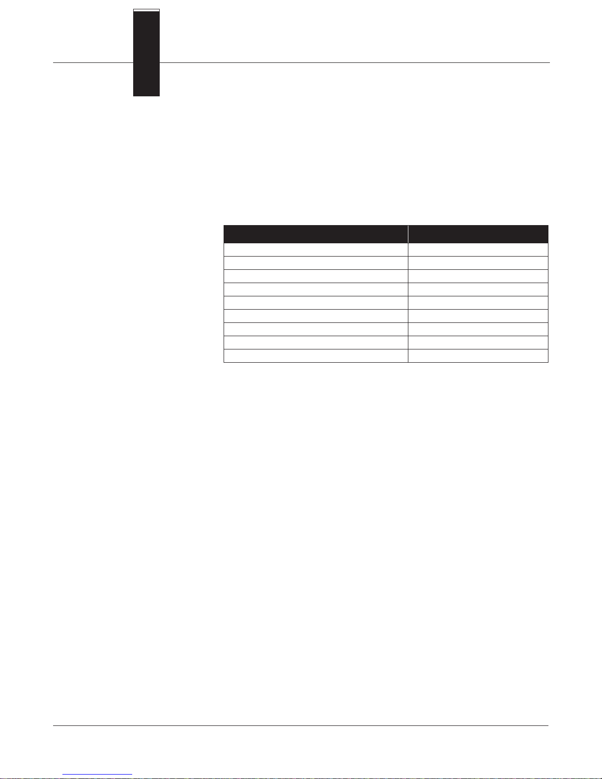
Set-up Parameters Page
Basic Configuration 4-4
Special Units Configuration 4-5
Analog Output Configuration 4-6
Digital Output Configuration 4-8
Totalizer Configuration 4-11
Noise Reduction 4-12
Calibration 4-14
Transmitter Information Configuration 4-15
Multidrop Communications 4-18
4-1
Page 48
Rosemount Model 8732C Integral Mount Magnetic Flowmeter System
SAFETY MESSAGES
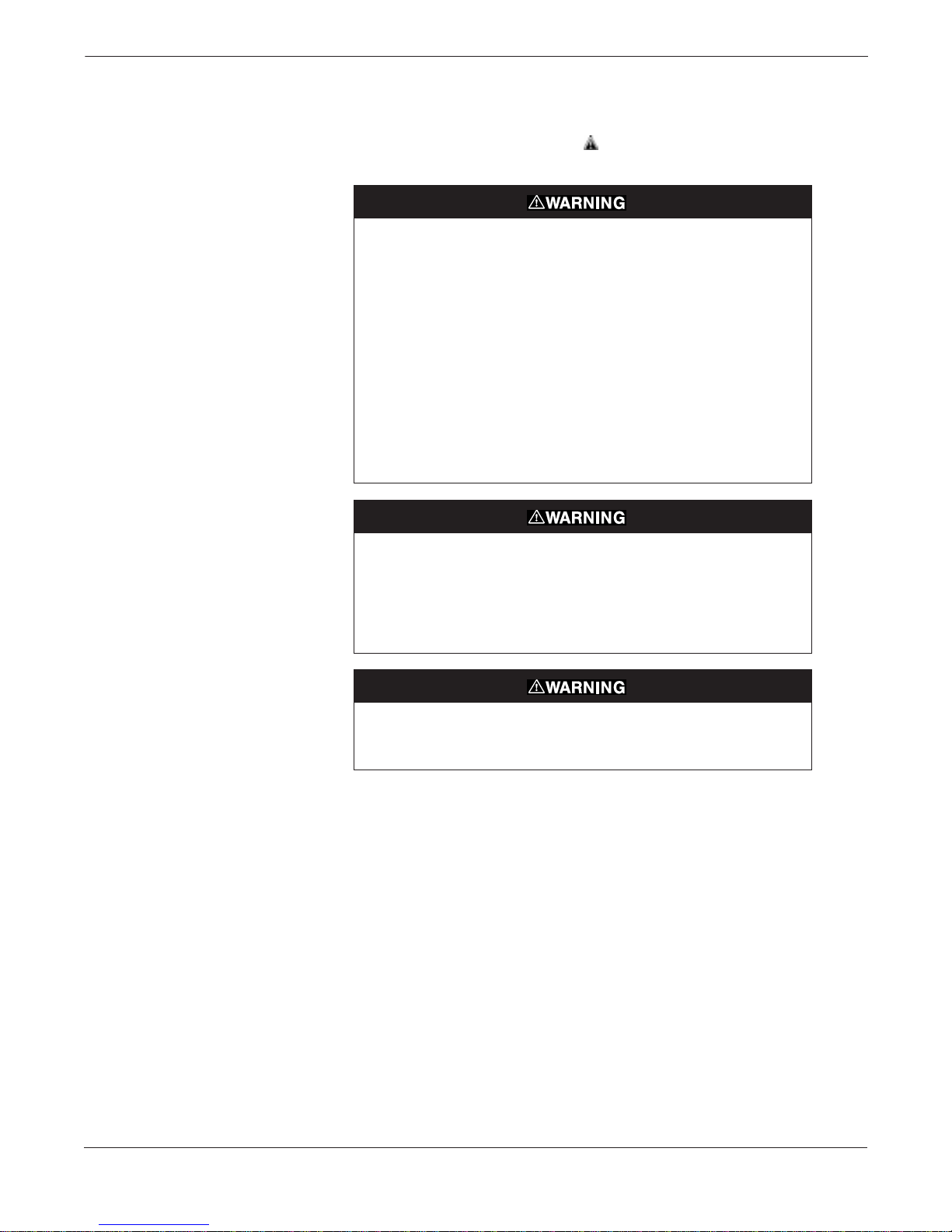
Instructions and procedures in this section may require special
precautions to ensure the safety of the personnel performing
the operations. Information that raises potential safety issues is
indicated by a warning symbol ( ). Please refer to the following safety
messages before performing an operation preceded by this symbol.
Explosions could result in death or serious injury:
• Verify that the operating atmosphere of the flowtube and transmitter is
consistent with the appropriate hazardous locations certifications.
• Do not remove the transmitter cover in explosive atmospheres
when the circuit is alive.
• Before connecting a HART-based communicator in an explosive
atmosphere, make sure the instruments in the loop are
installed in accordance with intrinsically safe or non-incendive field
wiring practices.
• Do not make connections to the HART Communicator’s serial port or
NiCad recharger jack in an explosive atmosphere.
• Both transmitter covers must be fully engaged to meet
explosion-proof requirements.
Failure to follow safe installation and servicing guidelines could result in
death or serious injury:
• Make sure only qualified personnel perform these procedures.
• Do not perform any service other than those contained in this manual
unless qualified.
High voltage that may be present on leads co uld cause electri cal sh ock :
• Avoid contact with leads and terminals.
4-2
Page 49
Transmitter Functi ons
REVIEW VARIABLES
Before operating the Model 8732C in an actual installation, review all
of the factory set configuration data to ensure that they reflect the
current application.
Review Review the flowmeter configuration parameters set at the factory to
HART Fast Keys
1, 5
ensure accuracy and compatibility with your particular application of
the flowmeter.
NOTE
If you are using the LOI to review variables, each variable must be
accessed as if you were going to change its setting. The value displayed
on the LOI screen is the configured value of the variable.
If you need to make any changes to flowmeter configuration data, see
Basic Configuration on page 4-4 for additional information.
CHECK OUTPUT
VARIABLES
Next, check the transmitter output. Model 8732C digital outputs
include: flow rate (PV), pulse output, measure gross total, measure net
total, and measure reverse total. The settings should be reviewed to
ensure that the flowmeter is operating properly.
Process Variables
HART Fast Keys
1, 1
The Process Variables for the Model 8732C provide the flowmeter
output. They measure flow in several ways that reflect your needs and
the configuration of your flowmeter.
LOI
Display Setup
When commissioning a flowmeter, review each process variable, its
function, and output. If you suspect a problem with the digital outputs,
you may need to reconfigure the transmitter or check the
troubleshooting table in Section 5: Troubleshooting.
PV – Process Variable is the actual configured flow rate in the line.
On the bench, the PV value should be zero. Check the units on
the PV to make sure they are configured correctly. If the units
format is not correct, see Units on page 4-4.
Puls Out – Pulse Output provides the actual pulse reading from the
meter if your transmitter is configured for pulse output.
Measure gross totl – Measure Gross Total provides a reading of the
total forward flow since the totalizer was last reset. The totalizer value
should be zero during commissioning on the bench, and the units
should reflect the volume units of the flow rate. If the totalizer value is
not zero, it may need to be reset (see Totalizer Display on page 4-11).
Measure net totl – Measure Net Total provides a reading of the net
totalized flow in the forward direction. The net totalize value can be
reset using the HART Communicator (1, 1, 4, 6) or the LOI.
Measure reverse totl – Measure Reverse Total provides a reading of
the total flow of process fluid in the reverse direction.
4-3
Page 50
Rosemount Model 8732C Integral Mount Magnetic Flowmeter System
BASIC CONFIGURATION
The basic configuration functions of the Model 8732C must be set for all
applications of the transmitter in a magnetic flowmeter system. If your
application requires the advanced functionality features of the Model
8732C, see Special Units Configuration on page 4-5.
Units Units variable specifies the format in which the flow rate will be
HART Fast Keys
LOI
1, 3, 2
Basic Setup
displayed. Units should be selected to meet your particular metering
needs. The choices are shown below:
Choices
• Gal/Min • Ft/Sec
• Liters/Min • Meters/Sec
• ImpGal/Min • Liters/Sec
• CuMeter/Min • Special
The maximum flow rate information is not updated as the available
units appear, but only after the data are entered. The maximum flow
rate on the second line of the display is for informational purposes, and
cannot be changed directly by the user.
If the transmitter is totalizing, the numerator of the unit of measure is
used by the transmitter as the volumetric unit for totalization and
pulse output scaling. For example, if gal/min is selected, the Model
8732C totalizes and provides a pulse output in gallons.
Line Size Line Size (tube size) must be set to match the actual flowtube
HART Fast Keys 1, 3, 5
LOI Basic Setup
connected to the transmitter. The size is set at the factory before the
flowtube is shipped. If a value is entered from a control system or
HART Communicator that does not match one of these figures, the
value will be rounded to match the nearest choice.
The tube size choices available are as follows:
0.15, 0.30, 0.50, 1, 1.5, 2, 3, 4, 6, 8, 10, 12, 14, 16, 18, 20, 24,
30, 36, 42, 48, 54, 60 (inches).
NOTE
The second line on the LOI screen, MAX FLOW, is strictly for
informational purposes and indicates the maximum flow rate for a
given line size.
Tube Cal. Number The tube calibration number is a 16-digit number used to identify
HART Fast Keys
LOI
1, 3, 6
Basic Setup
flowtubes calibrated at the Rosemount factory. It provides detailed
calibration information to the Model 8732C. This number is set at the
factory before the flowmeter is shipped.
Upper Range Value Upper Range Value (URV) is preset to 30 ft/s at the factory. The units that
HART Fast Keys
LOI
1, 3, 3
Basic Setup
appear will be the same as those selected under the units parameter.
The URV (20 mA point) can be set for any forward or reverse flow rate.
Flow in the forward direction is represented by positive values; flow in
the reverse direction is represented by negative values. The UR V can be
any value from –30 ft/s to +30 ft/s, as long as it is at least 1 ft/s from the
Lower Range Value (LRV)(4 mA point). The URV can also be set to a
value less than the LRV, which would cause the transmitter analog
output to operate in reverse, with the electrical current increasing for
lower (or more negative) flow rates.
4-4
Page 51
Transmitter Functi ons
SPECIAL UNITS
CONFIGURATION
The Model 8732C provides a selection of standard units configurations
that meet the needs of most applications (see Units on page 4-4). If,
however, your application has special needs and the standard
configurations do not apply, the Model 8732C provides the flexibility to
configure the transmitter in a custom-designed units format.
NOTE
For flowtubes larger than 36 inches (900 mm), line size must be
selected prior to configuration of special units. If special units are
configured first, the communication interface may not display the
correct flow rate.
To configure a special unit, set values for each function listed below.
Volume Unit Volume Units enables you to display the volume unit format to which
HART Fast Keys 1, 3, 2, 2, 4
LOI Detailed Setup
you have converted the base volume units. For example, if the special
units are abc/min, the special volume variable is abc. This variable is
also used in totalizing the special units flow.
Base Volume Unit Base Volume Unit is the unit from which the conversion is being
HART Fast Keys 1, 3, 2, 2, 1
LOI Detailed Setup
made. Set this variable to the appropriate option.
Conversion Number Conversion Number is used to convert base units to special units. For
HART Fast Keys
LOI
1, 3, 2, 2, 3
Detailed Setup
a straight conversion of volume units from one to another, t he
conversion number is the number of base units in the new unit. For
example, if you are converting from gallons to barrels and there are 31
gallons in a barrel, the conversion factor is 31.
Base Time Unit Base Time Unit provides the time unit from which to calculate the
HART Fast Keys 1, 3, 2, 2, 2
LOI Detailed Setup
special units. For example, if your special units is a volume per
minute, select minutes.
Flow Rate Unit Flow Rate Unit is a format variable that provides a record of the units to
HART Fast Keys
LOI
1, 3, 2, 2, 5
Detailed Setup
which you are converting. The HART Communi cator and Mod el 8732C
will display a special un its designator a s the units f ormat for your prim ary
variable. The actual spec ial uni ts settin g you define will not appear. There
are four characters available to stor e the new units designation .
Example
Suppose you work for a brewery, and want the Model 8732C to display
flow in barrels per hour. One barrel of beer is equal to 31.0 gallons. You
would set the following:
Volume Unit = BARL.
Base Volume Unit = Gallons.
Input Conversion Number = 31.
Time Base = Hour.
Rate Unit = BR/H.
4-5
Page 52
Rosemount Model 8732C Integral Mount Magnetic Flowmeter System
ANALOG OUTPUT
CONFIGURATION
The standard 4–20 mA analog output can be configured to meet the
special requirements of your application. In the standard configuration,
a 4 mA output (LRV) corresponds to 0.0 ft/s in the line, while a 20 mA
output (URV) corresponds to a maximum flow of 30 ft/s. The 4 and 20
mA output points can be changed to any value between –30 ft/s and 30
ft/s. The minimum allowable range between them is 1 ft/s.
Upper Range Value (URV) Reset the Upper Range Value (URV) to change the size of the range
HART Fast Keys
LOI
1, 3, 3
Basic Setup
(or span) between the URV and LRV. Under normal circumstances, the
URV should be set to a value near the maximum expected flow rate and
must be between –30 ft/s to 30 ft/s.
NOTE
The minimum span between the analog output range (URV) and analog
output zero (LRV) is 1 ft/s.
Lower Range Value (LRV) Reset the Lower Range Value (LRV) to change the size of the range
HART Fast Keys
LOI
1, 3, 4
Basic Setup
(or span) between the URV and LRV. Under normal circumstances, the
LRV should be set to a value near the minimum expected flow rate to
maximize resolution. LRV must be between –30 ft/s to 30 ft/s.
NOTE
The LRV can be set to a value greater than the URV, which will cause
the analog output to operate in reverse. In this mode, the analog output
will increase with lower (more negative) flow rates.
Example
If the URV is greater than the LRV, the analog output becomes 3.9 mA
when the flow rate falls below the selected 4 mA point.
If the URV is less than the LRV, the analog output becomes 3.9 mA
when the flow rate rises above the selected 4 mA point.
The minimum allowable span between the URV and LRV is 1 ft/s. Do
not set the LRV within 1 ft/s of the 20 mA point. For example, if the
URV is set to 15.67 ft/s and if the desired URV is greater than the LRV,
then the highest allowable LRV would be 14.67 ft/s. If the desired URV
is less than the LRV, then the lowest allowable analog zero setting
would be 16.67 ft/s.
4-6
Page 53
Transmitter Functi ons
4–20 mA Output Trim For maximum accuracy, the analog output should be calibrated and, if
HART Fast Keys
LOI
1, 2, 4, 1
Transmitter Trim
necessary, trimmed for your system loop. The 4–20 mA Output Trim
procedure alters the conversion of the digital signal into an analog
4–20 mA output.
Use the following steps to complete this function.
1. Set the loop to manual, if necessary.
2. Connect a precision ammeter to the 4–20 mA loop.
3. Initiate the Output Trim function with the LOI or
HART Communicator.
4. Enter the 4 mA meter value when prompted to do so.
5. Enter the 20 mA meter value when prompted to do so.
6. Return the loop to automatic control, if necessary.
The 4–20 mA trim is now complete. You may repeat the 4–20 mA trim
to check the results, or use the analog output test.
Loop Test The Loop Test allows you to drive the transmitter output to a desired
HART Fast Keys 1, 2, 2
LOI Transmitter Test
electric current output on the 4–20 mA terminals. This capability
allows you to check the entire current loop prior to start-up. The test
will terminate after five minutes if the transmitter is not returned to
normal operation manually.
4-7
Page 54

Rosemount Model 8732C Integral Mount Magnetic Flowmeter System
DIGITAL OUTPUT
Pulse Output Scaling equates one transistor switch closure pulse to a
selectable number of volume units. The volume unit used for scaling
pulse output is taken from the numerator of the configured flow units.
For example, if gal/min had been chosen when selecting the flow rate
unit, the volume unit displayed would be gallons.
NOTE
The scaled pulse output is designed to operate between 0 and 1000 Hz.
The electronics will not accept a conversion factor that would result in a
pulse frequency outside that range. The minimum conversion factor
value is found by dividing the uppe r range value (in u nits of volume p er
second) by 1000 Hz.
When selecting pulse output scaling, remember that the maximum
pulse rate is 1000 Hz. With the 110 percent overrange capability, the
absolute limit is 1100 Hz. For example, if you want the Model 8732C to
pulse every time 0.01 gallons pass through the flowtube, and the flow
rate is 1000 gal/min, you will exceed the 1000 Hz full-scale limit:
---------------------------------------------------------------------------
60 sec/min 0.01 gal/pulse×
1000 gal/min
1666.65 Hz=
The best choice for this parameter depends upon the required
resolution, the number of digits in the totalizer, the extent of range
required, and the maximum counter input frequency.
NOTE
When totalizing on the LOI, the maximum total value is 1,000,000,000.
Auxiliary Output Control In lieu of the pulse output on the digital terminals, an Auxiliary
HART Fast Keys 1, 4, 3, 2
LOI Detailed Setup
Output Control is available to indicate a reverse flow or zero flow
condition. The two terminals are actually a transistor switch closure,
which must be externally powered.
Reverse Flow Enable
This choice activates the switch closure with a reverse flow. A forward
flow is defined by the flow direction arrow on the flowtube. This also
enables the totalizer to count in the reverse direction.
No Flow Enable
This choice activates the switch closure whenever the flow rate drops
below the low flow cutoff.
4-8
Page 55
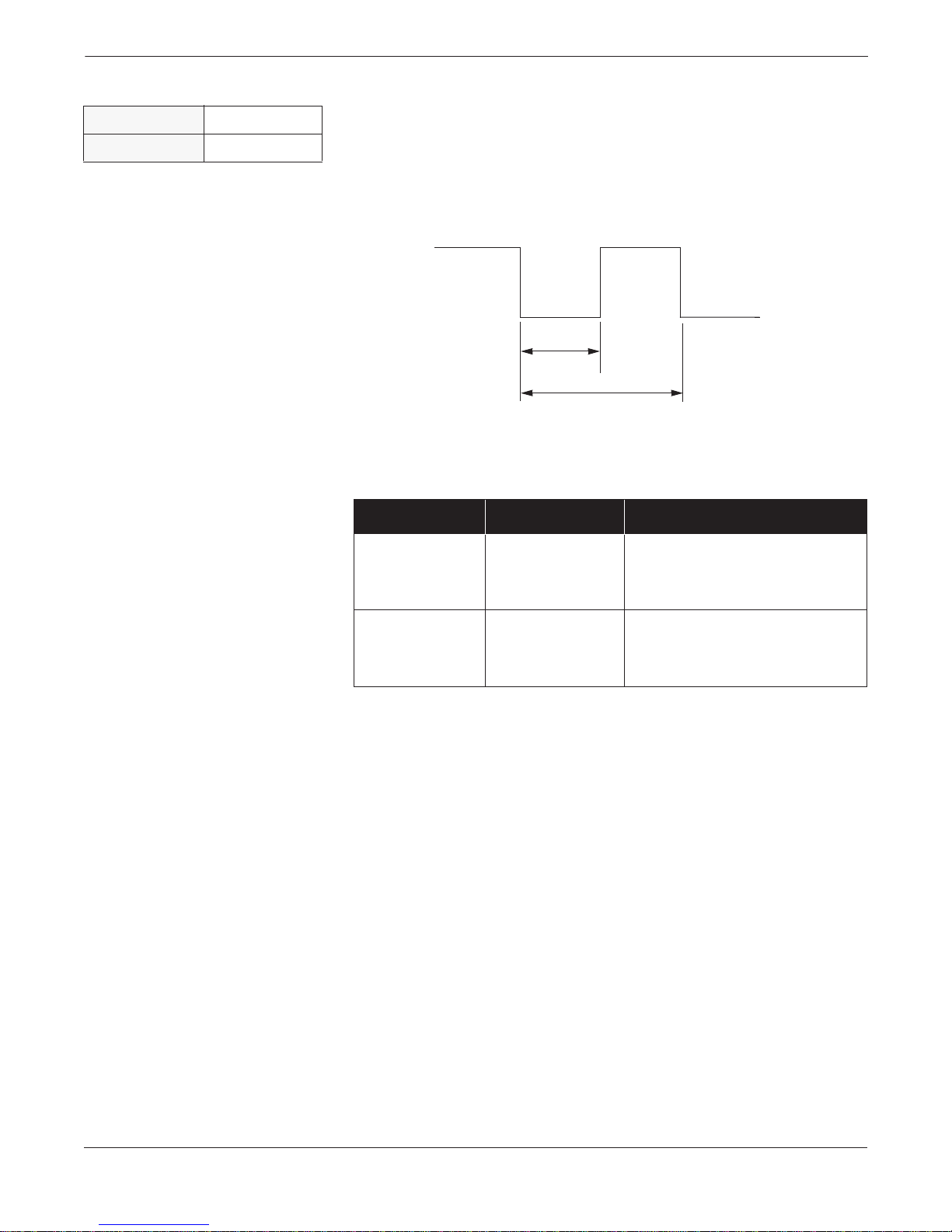
Transmitter Functi ons
Pulse Width Pulse Width, or duration, of the frequency output pulse can be
HART Fast Keys
LOI
FIGURE 4-1. Pulse Output.
1, 4, 3, 3, 2
Detailed Setup
adjusted to match the requirements of different counters
or controllers (See Figure 4-1). The pulse width adjusts the
time that the switch is closed.
OPEN
CLOSED
Pulse
Width
Period
Example
For example, if pulse width is set to 100 ms, the maximum output is 5
Hz; for a pulse width of 0.5 ms, the maximum output would be 1000 Hz.
(At the maximum frequency output there is a 50 percent duty cycle.)
PULSE WIDTH MINIMUM PERIOD
(50% duty cycle)
100 ms 200 ms
0.5 ms 1.0 ms
MAXIMUM FREQUENCY
1 Cycle
--------------- -
200 ms
1 Cycle
-------------- -
1.0 ms
5Hz=
1000 Hz=
To achieve the greatest maximum frequency output, set the pulse width
to the lowest value that is consistent with the requirements of the
pulse output power source, pulse driven external totalizer, or other
peripheral equipment.
4-9
Page 56

Rosemount Model 8732C Integral Mount Magnetic Flowmeter System
Example
The external counter is ranged for 350 gpm. You want to set 1 pulse for
every gallon of flow. What is the maximum frequency output? (Assume
the pulse width = 0.5 ms.)
Frequency
=
------------------------------------------------------------------------------------- -
(60 s/min)(Pulse Scaling gal/pulse)
=
------------------------------------------------------ -
(60 s/min)(1 gal/pulse)
Flow Rate (gpm)
350 gpm
5.833 Hz=
Example
Set the pulse output scaling to get the most accurate reading from the
totalizer (highest resolution). The 20 mA point = 3,000 gpm.
(Hint: Range 1000 Hz to full scale analog reading.)
Pulse Scaling
Flow Rate (gpm)
=
----------------------------------------------------- -
(60 s/min)(Frequency)
=
3000 gpm
-----------------------------------------------
(60 s/min)(1000Hz)
0.05 gal/pulse=
1 Pulse 0.05 gallon=
4-10
Page 57

Transmitter Functi ons
TOTALIZER
CONFIGURATION
The totalizer tracks total flow in the process line. You can start, stop, or
reset the totalizer as well as configure it to present the data specific to
your application on the LOI display.
Totalizer Display On the LOI, the Totalizer Display allows you to choose the desired
HART Fast Keys
LOI
1, 1, 4
Display Setup
format for indicating the totalized values. You may choose either
forward-reverse or net-gross for displaying totalized values.
On the HART Communicator, Gross, Net, and Reverse values are
always available.
Forward-Reverse
Forward-Reverse shows both the forward and reverse totalized values,
updating continuously. You must choose reverse flow enable to allow
totalizing in the reverse direction.
These values cannot be reset by using the totalizer reset button. Reset
them by doing one of the following:
• Change the pulse scaling.
• Change the tube size.
• Change the units.
• Power down a transmitter that is not equipped with the
non-volatile totalizer option.
Net-Gross
Net-Gross shows both net and gross total values. It updates contin uously.
The net value can be reset by the operator. The gross value cannot be reset
by using the
→ button. Reset it indirectly by d oing one of the foll owing:
• Change the pulse scaling.
• Change the tube size.
• Change the units.
• Power down a transmitter that is not equipped with the
non-volatile totalizer option.
To prevent an operator from accidentally resetting the gross value, the
Software Protect jumper on the electronics board should be in the ON
position. This action does not block the functions of the
E ← and →
buttons for starting and stopping or reading and resetting the totals.
Example
If you had a batch-type process, you would use the net value to measure
each batch and then have the operator reset it. In addition, the gross
value would keep track of a period of production (e.g., eight hour shift,
day, week, month). The gross value could be reset by cycling power to
the unit (if not equipped with a backed totalizer battery) or changing
one of the parameters described above.
4-11
Page 58
Rosemount Model 8732C Integral Mount Magnetic Flowmeter System
NOISE REDUCTION
Damping Damping allows selection of a response time, in seconds, to a step change in
HART Fast Keys
1, 3, 7
flow rate. It is most often used to smooth fluctuations in output.
LOI
Basic Setup
Coil Frequency Coil Frequency allows pulse-rate selection of the flowtube coils.
HART Fast Keys
LOI
1, 4, 4, 3
Detailed Setup
6 Hz
The standard coil pulse mode is 6 Hz, which is sufficient for
nearly all applications.
30 Hz
If the process fluid causes a noisy or unstable output, increase the coil
pulse mode to 30 Hz. If the 30 Hz mode is selected, perform the Auto
Zero function as shown below.
Auto Zero Auto Zero initializes the transmitter for use with the 30 Hz coil drive
HART Fast Keys 1, 2, 4, 4
LOI Transmitter Trim
mode only. Run this function only with the transmitter and flowtube
installed in the process. The flowtube must be filled with process fluid
at zero flow. Before running the auto zero function, be sure the coil
drive mode is set to 30 Hz.
Set the loop to manual if necessary. Then, begin the auto zero procedure. The
transmitter completes the procedure automatically i n about two minutes. A
symbol appears in the lower right-hand c orner of the display to indicate that
the procedure is running.
Low Flow Cutoff Low Flow Cutoff allows you to specify the flow rate, between 0.001
HART Fast Keys
LOI
1, 4, 4, 1
Detailed Setup
and 1.0 foot per second, belo w wh ich the outputs are driven to zero flow.
The units format for low flow cutoff cannot be changed. It is always
displayed as feet per second regardless of the format selected. The low
cutoff value applies to both forward and reverse flows.
Signal Processing Signal Processing is a software algorithm that examines the quality
HART Fast Keys
LOI
1, 4, 4
Detailed Setup
of the electrode signal against user-specified tolerances. If spurious
noise spikes are detected, they are automatically rejected. There are
three parameters associated with this function:
• Number of samples (0 to 125)
• Maximum percent limit (0 to 100 percent of running average)
• Time limit (0 to 256 seconds)
4-12
Page 59
Signal Processing Control Signal Processing Control — On/Off
HART Fast Keys
LOI
1, 4, 4, 4
Detailed Setup
When ON is selected, the Model 8732C output is derived using a running
average of the individual flow inputs. This average is updated at the rate
of 12 samples per second regardless of the selected coil drive mode. The
three parameters that make up Signal Processing Control: Number of
samples, maximum percent limit, and time limit. They are described
individually below.
Transmitter Functi ons
Number of Samples
HART Fast Keys
LOI
0 to 125 Samples
1, 4, 4, 5
Detailed Setup
Maximum Percent Limit
HART Fast Keys
LOI
Time Limit
HART Fast Keys
LOI
0 to 256 Seconds
1, 4, 4, 6
Detailed Setup
1, 4, 4, 7
Detailed Setup
The number of samples function sets the number of previous inputs
used to calculate the average value. Because the output stage of the
Model 8732C circuit is updated twelve times each second,
regardless of 6 or 30 Hz coil drive mode, the factory preset value of 90
samples equates to 7.5 seconds. For example, if you select a sample
number of 120, the response time of the system will be 10 seconds
(120 samples
÷ 12 samples per second). A sug gested nominal number of
90 samples is a good starting point for most applicable process fluids.
0 to 100 Percent
The maximum percent limit is a tolerance band set up on either side
of the running average. The percentage value refers to deviation from
the running average. For example, if the running average is 100 gal/
min, and a 2 percent maximum limit is selected, then the acceptable
range is from 98 to 102 gal/min.
Values within the limit are accepted while values outside the limit are
analyzed to determine if they are a noise spike or an actual flow change.
This parameter forces the output and running average values to the
new value of an actual flow rate change that is outside the percent limit
boundaries. It thereby limits response time to flow changes to the time
limit value rather than the length of the running average.
For example, if the number of samples selected is 120, then the
response time of the system is 10 seconds. In some cases this may be
unacceptable. By setting the time limit, you can force the Model 8732C
to clear the value of the running average and re-establish the output
and average at the new flow rate once the time limit has elapsed. This
parameter limits the response time added to the loop. A suggested time
limit value of 2 seconds is a good starting point for most applicable
process fluids. The selected signal processing configuration may be
turned ON or OFF to suit your needs.
4-13
Page 60

Rosemount Model 8732C Integral Mount Magnetic Flowmeter System
CALIBRATION
The Model 8732C offers the calibration functions described below.
Gain (Electronics) Trim Gain Trim is the function by which the fact ory calibrates the tr ansmitter.
HART Fast Keys
LOI
1, 2, 4, 3
Transmitter Trim
This procedure is rarely needed by customers. It is only necessary if you
believe the Model 8732C is no longer acc urate. It must be perfor med with
the coil drive mode set to 6 Hz and with a nomin al flowt ube calibra tion
number stored in the memory.
Attempting an electronics trim without a Model 8714D may result in an
inaccurate transmitter, or a “DIGITAL TRIM FAILURE” message may
appear. If this message occurs, no values were changed in the
transmitter . Simply power down the Model 8732C to clear the message.
If the trim was completed or no error message appears, correction
requires a Model 8714D.
To simulate a nominal flowtube with the Model 8714D, you must
change the following parameters in the Model 8732C:
• Tube Calibration Number:1000015010000000
• Units: ft/s
• Upper Range Value: 20 mA = 30.00 ft/s
• Lower Range Value: 4 mA = 0 ft/s
• Coil Frequency: 6 Hz
The instructions for changing these parameters are located in the
parameter descriptions in this section. Set the loop to manual, if
necessary, before you begin. Complete the following steps:
1. Power down the transmitter.
2. Connect the transmitter to a Model 8714D Flowtube Simulator.
3. Power up the transmitter with the Model 8714D connected
and read the flow rate. The electronics need about a 30-minute
warm-up time to stabilize.
4. The flow rate reading after warm-up should be between
29.97 and 30.03 ft/s.
5. If the reading is within the range, return the transmitter to the
original configuration parameters.
6. If the reading is not within this range, initiate an electronics trim
with the LOI or HART Communicator. The gain trim takes about
6 minutes to complete. No transmitter adjustments are required.
4-14
Page 61
Transmitter Functi ons
TRANSMITTER
INFORMATION
CONFIGURATION
This function allows you to view and change identification data and
other information about the transmitter and flowtube. This information
does not affect the performance or operation of the transmitter; it is
strictly for information purposes (exceptions are noted below).
Transmitter Tag Transmitter Tag is the quickest and shortest way of identifying and
HART Fast Keys
LOI
1, 4, 5, 2
Device Information
distinguishing between transmitters. Transmitters can be tagged
according to the requirements of your application. The tag may be
up to eight characters long and is user-defined.
Software Revision Number The Model 8732C microcontroller will automatically read the Software
HART Fast Keys
LOI
1, 4, 5
Device Information
Revision Number and display it under this heading. The software
revision number is not user-changeable.
Descriptor Descriptor is a longer user-defined variable to assist with more
HART Fast Keys 1, 4, 5, 3
LOI Device Information
specific identification of the particular transmitter. It is usually used in
multi-transmitter environments and provides 16 characters.
Message Message Variable provides an even longer user-defined variable
HART Fast Keys 1, 4, 5, 4
LOI Device Information
for identification and other purposes. It provides 32 characters of
information and is stored with the other configuration data.
Date Date is a user-defined variable that provide s a place to save the date of
HART Fast Keys
1, 4, 5, 5
the last revision of configuration information.
LOI
Device Information
Flowtube Tag Flowtube Tag is the quickest and shortest way of identifying and
HART Fast Keys
LOI
1, 4, 5, 8
Device Information
distinguishing between Flowtubes. Flowtubes can be tagged according
to the requirements of your application. The tag may be up to eight
characters long and is user-defined.
Flowtube Serial Number Flowtube Serial Number is stored in the transmitter configuration
HART Fast Keys
LOI
1, 4, 5, 7
Device Information
for future reference. The number provides easy identification if the
flowtube needs servicing or for other purposes.
4-15
Page 62
Rosemount Model 8732C Integral Mount Magnetic Flowmeter System
Liner Material Liner Material enables you to select the liner material for the attached
HART Fast Keys
LOI
1, 4, 5
Device Information
flowtube. This variable needs to be ch anged only if you have replaced
your flowtube.
• PTFE Teflon
• ETFE Tefzel
• Polyurethane
• Natural Rubber
• Neoprene
• Ryton
• Other
Electrode Type Electrode T y pe enables you to select the electrode type for your magnetic
HART Fast Keys
LOI
1, 4, 5
Device Information
transmitter system. This varia ble n eeds t o b e c hanged only if you h ave
replaced electrodes in the hardware.
• Standard
• Std and Ground
• Bullet
• Other
Electrode Material Electrode Material enables you to select the electrode material for
HART Fast Keys
LOI
1, 4, 5
Device Information
your magnetic transmitter system. This variable needs to be changed
only if you have replaced electrodes in the hardware.
•316L SST
• Hast-C 276
• Tantalum
• Pt–Ir
• Titanium
• Ryton
• Alloy 20
• Other
4-16
Page 63
Transmitter Functi ons
Flange Type Flange Type enables you to specify the type of flange on the transmitter for
HART Fast Keys
LOI
1, 4, 5
Device Information
later reference. This variable is preset at the fac tory but can be ch anged
if necessary.
• ANSI 150
• ANSI 300
• ANSI 600
• ANSI 900
• PN 10
• PN 16
• PN 25
• PN 40
• PN 64
• Flangeless
• Other
Flange Material Flange Material is a factory-set configuration variable that reflects
HART Fast Keys 1, 4, 5
LOI Device Information
the construction of your flowtube.
• Carbon steel
• 304 SST
•316L SST
• Flangeless
• Other
For flowtubes without flanges, this screen can be ignored or used to
indicate the adjacent pipe flange material.
4-17
Page 64
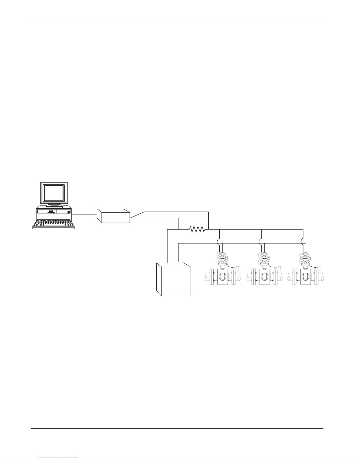
Rosemount Model 8732C Integral Mount Magnetic Flowmeter System
MULTIDROP
COMMUNICATIONS
FIGURE 4-2. Typ ical Multid rop Network.
Multidrop configuration refers to the connection of seve ral transmitters
to a single communications transmission line. Communication between
the HART Communicator and the transmitters takes place digitally
with the analog output of the transmitters deactivated. Using the
HART communications protocol, up to 15 transmitters can be connected
on a single twisted pair of wires or over leased phone lines.
The use of a multidrop installation requires consideration of the update
rate necessary from each transmitter, the combination of transmitter
models, and the length of the transmission line. Multidrop installations
are not recommended where intrinsic safety is a requirement.
Communication with the transmitters can be accomplished with
commercially available Bell 202 modems and a host implementing the
HART protocol. Each transmitter is identified by a unique address
(1-15) and responds to the commands defined in the HART protocol.
Figure 4-2 shows a typical multidrop network. This figure is not
intended as an installation diagram. Contact Rosemount product
support with specific requirements for multidrop applications.
RS-232-C
Bell 202
Modem
4–20 mA
Power
Supply
3051-0087A, 8712-8712B01B
4-18
Page 65
Transmitter Functi ons
The HART Communicator can test, configure, and format a
multidropped Model 8732C in the same way as it can a Model 8732C in
a standard point-to-point installation.
NOTE
The Model 8732C is set to poll address zero at the factory, allowing it to
operate in the standard point-to-point manner with a 4–20 mA output
signal. To activate multidrop communication, the transmitter poll
address must be changed to a number between 1 and 15. This change
deactivates the 4–20 mA analog output, sending it to 4 mA. It also
disables the failure mode alarm signal.
Auto Poll When the HART Communicator is po were d u p and auto p olling is o n, i t
HART Fast Keys
OFF LINE FCN
automatically polls the transmitter addresses to which it is connected.
If the address is 0, the HART Communicator enters its normal on-line
mode. If it detects an address other than 0, the communicator finds
each device in the loop and lists them by poll address and tag number.
Use the action keys to scroll through the list and select the transmitter
with which you need to communicate.
If a single connected device has an address other than zero and auto
polling is off, the device will not be found.
Poll Address Poll Address enables you to set the poll address for a multi-dropped
HART Fast Keys
1, 4, 4, 3, 1
meter. The poll address is used to identify each meter on the multi-drop
line. Follow the on-screen instructions to set the address at a number
from 1 to 15. To set or change the flowmeter address, establish
communication with the selected Model 8732C in the loop.
4-19
Page 66

Rosemount Model 8732C Integral Mount Magnetic Flowmeter System
4-20
Page 67
Section
5 Troubleshooting
BASIC
TROUBLESHOOTING
SAFETY MESSAGES
Problems in the magnetic flowmeter system are usually indicated by
incorrect output readings from the system, error messages, or failed
tests. Consider all sources when identifying a problem in your system.
Instructions and procedures in this section may require special
precautions to ensure the safety of the personnel performing the
operations. Please read the following safety messages before
performing any operation described in this section.
Explosions could result in death or serious injury:
• Verify that the operating atmosphere of the flowtube and transmitter is
consistent with the appropriate hazardous locations certifications.
• Do not remove the transmitter cover in explosive atmospheres
when the circuit is alive.
• Before connecting a HART-based communicator in an explosive
atmosphere, make sure the instruments in the loop are
installed in accordance with intrinsically safe or non-incendive field
wiring practices.
• Both transmitter covers must be fully engaged to meet
explosion-proof requirements.
Failure to follow safe installation and servicing guidelines could result in
death or serious injury:
• Make sure only qualified personnel perform the installation.
• Do not perform any service other than those contained in this manual
unless qualified.
High voltage that may be present on leads co uld cause electri cal sh ock :
• Avoid contact with leads and terminals.
5-1
Page 68

Rosemount Model 8732C Integral Mount Magnetic Flowmeter System
TABLE 5-1. Basic Troubleshooting–Model 8732C.
Symptom Po tential Cause Corrective Action
Output at 0 mA. No power to transmitter. Check powe r sou rce and conn ection s to the transmitt er.
Analog output improperly
configured.
Electronics failure. Replace the electron ics bo ard s.
Output at 4 mA. Transmitter in multidrop mode. Con fig ure Po ll Add res s to 0 to take tran smitter out of multidrop mode.
Low Flow Cutoff set too high. Configure Low Flow Cutoff to a lower setting or increase flow to a value
Flow is in reverse direction. Enable Reverse Flow function.
Shorted coil. Coil che ck. Perfo rm flowt ub e test A and B on pag e 5-5 .
Empty pipe. Fill pipe.
Electronics failure. Replace the electron ics bo ard s.
Output at 21.6 mA. Transmitter not ranged properly. Reset the transmi tt er rang e v alu es. S ee Lower Range Value (LRV) and
Output at alarm level. Electronics failure. Cycle power. If alarm is still prese n t, rep la ce the elec tron ics b oards .
Pulse output at zero,
regardless of flow.
Communication problems with
the HART Communicator.
Error Messages on LO I
or HART Communicator
No power to transmitter. Check powe r sou rce and conn ection to the tran smitte r.
Wiring error. Check pulse output wiring at digital output terminals. Refer to wiring
Reverse flow. Enable Reverse Flow function.
Pulse width too wide or too narrow. Reset Pulse Width. See Pulse Width on page 4-9.
Electronics failure. Replace the electron ics bo ard s.
4–20 mA output configuration. Check analog power switch (internal/external). HART Communicator
Communication interface wiring
problems.
Low batteries in the HART
Communicator.
Old revision of software in the
HART Communicator.
Many possible causes depending
upon the message.
Check the analog power switch. See Hardware Swit ches on pag e 2-2 for
proper settings.
above the low flow cutoff.
Upper Range Value (URV) on page 4-6.
Check tube size setting in tran smitte r an d mak e sure it match e s you r
actual tube size. See Line Size on page 4-4.
diagram for pulse output.
requires a 4–20 mA output to function.
Incorrect load resistanc e (250 V minimum).
Check appropriate wirin g diag ra m in Appe ndix A.
Replace the batteries in the HART Communicator. See the communicator
manual for instructions.
Consult your local sales office about updating to the latest
revision of software.
See the Error Messages Table for the LOI (Table 3-3) or the Diagnost ic
Messages for the HART Communicator (Table A-2).
5-2
Page 69
Troubleshooting
ADVANCED
TROUBLESHOOTING
Process Noise
If your system is experiencing problems and the basic troubleshooting
steps do not address your problem, use the following advanced
troubleshooting procedures or call your service representative. The
procedure for advanced troubleshooting is as follows:
1. Consider symptoms in the basic troubleshooting table.
2. Consider symptoms in the advanced troubleshooting table.
3. Run the software tests, if possible.
4. Perform the flowtube tests to see if flowtube must be removed
from the process line.
5. If the problem persists, contact your sales or service
representative.
In some circumstances, process conditions themselves can cause the
meter output to be unstable. The basic procedure for addressing a noisy
process situation is outlined below. Complete them in order. When the
output attains the desired stability, no further steps are required.
Noisy Conditions Basic Procedure
1. Change coil drive to 30 Hz.
2. Increase the damping.
3. Activate signal processing.
4. Consult Rosemount Sales Representative about using
a High-Signal Magnetic Flowmeter System.
TABLE 5-2. Advanced Troubleshooting–Model 8732C.
Accuracy
Symptom Potentia l Cause Corrective Action
Reading doesn’t appear to be
within rated accuracy.
Transmitter, control system, or other
receiving device not configured properly.
Electrode Coating. Use replaceable electrodes in Mode l 8705 .
Air in line. Move the flowtube to another location in the process line to
Flow rate is below 1 ft/s (specification
issue).
Auto zero was not perfo rm e d whe n the
coil drive frequency was changed from 6
Hz to 30 Hz.
Flowtube failure–Shorte d electrod e . Perform flowtube tests C and D on page 5-5.
Flowtube failure–Shorte d or open coil. Perform flowtube tests A an d B on page 5-5.
Transmitter failure. Replace the electronics boards.
Check all configura tio n va riab les fo r the tran smitt er,
flowtube, communicator, and/or control system. See
Process V ariables on page 4-3.
Check these other transmitter settings:
• Flowtube calibration number
• Units
• Line si ze
Perform a loop test to check the integrity if the circuit. See
Loop Test on page 5-4.
Downsize flowtub e to increa se flow rat e above 3 ft/s.
Periodically clean flowtube.
ensure that it is full under all conditions.
See accuracy specification for specific transmitter and
flowtube.
Perform the auto zero function. See Auto Zero on page
4-12.
5-3
Page 70
Rosemount Model 8732C Integral Mount Magnetic Flowmeter System
TABLE 5-2. Advanced Troubleshooting–Model 8732C.
Symptom Potentia l Cause Corrective Action
Noisy Process. Chemical additives upstream of
magnetic flowmeter.
Sludge flows–Mining/Coal/Sand/
Slurries (other slurrie s with hard
particles).
Styrofoam or other insulating particles in
process.
Electrode coating . Use replaceable ele ctro de s in Model 8705.
Air in line. Move the flowtube to another location in the process line to
Meter output is unstable. Electrode inc omp a tib i lit y. Check Magnetic Flow meter Material Selection Guid e
Improper grounding. Check ground wiring. See on page 2-14 for wiring and
High local magnetic or elect ric fie lds . Move magnetic flowmeter (20–25 ft. away is usu ally
Control loop improperly tuned. Check control loop tuning.
Sticky valve (look for periodic oscillation
of meter output).
Flowtube failure. Perform Flowtube Tests A, B, C, and D on page 5-5.
Analog output loop pro b lem. Check that the 4–20 mA loop matc he s the dig ita l va lu e.
Complete the Noisy Conditions Basic Procedure (page 5-3).
Move injection point downstream of magnetic flowmeter, or
move magnetic flowmeter.
Decrease flow rat e below 10 ft/s.
Complete the Noisy Conditions Basic Procedure (page 5-3).
Consult facto r y.
Use a smaller flowtube to increa se flow rat e abo ve 3 ft/s.
Periodically clean flowtube.
ensure that it is full under all conditions.
(00816-0100- 3033) for chemical compatibility with
electrode materi al.
grounding proce d ures.
acceptable).
Correct valve sticking.
Perform analog output test.
Software Testing
Loop Test The Loop Test drives the transmitter output to a desired electrical
HART Fast Keys
LOI
1, 2, 2
Transmitter Test
Pulse Output Test The Pulse Output Test allows you to drive the frequency output
HART Fast Keys
LOI Transmitter Test
1, 2, 3
Transmitter Test The Transmitter Test initiates a series of diagnostic tests that are not
HART Fast Keys
1, 2, 1, 2
current output on the 4–20 mA terminals. This capability allows
you to check the entire current loop prior to start-up. On the LOI the
test quits after five minutes if the transmitter is not returned
to normal operation manually.
at digital output terminals to a desired value. This capability allows
you to check auxiliary equipment prior to start-up. On the LOI the test
quits after five minutes if the transmitter is not manually returned to
normal operation.
performed continuously during normal operation. It performs the
following tests:
• Display Test
• RAM Test
•PROM Test
During the entire transmitter test, all outputs are driven to full-scale:
20 mA and 1,000 Hz. The test requires about 10 seconds to complete.
5-4
Page 71

Troubleshooting
Flowtube Troubleshooting
Procedures
The following tests can check Models 8705 or 8711 flowtubes in line and
full of process material. The tests allow you to determine whether or
not the flowtube needs to be removed from the process. The transmitter
must be removed to conduct these tests. Use the following procedure to
remove the transmitter:
Transmitter Removal Procedure 1. Remove power to the transmitter.
2. Remove the electronics compartment cover.
3. Carefully unhook the wires at the base of the electronics stack.
4. Remove the four bolts that attach the flowtube to the transmitter.
5. Carefully remove the housing, ensuring not to snag any wires.
6. Leave the wiring harness connected to the flowtube
terminal block.
T ransmitter Assembly Procedure Use the following procedure to reassemble the transmitter:
1. Carefully attach the electronics stack to the housing.
2. Secure the four bolts that attach the flowtube to the transmitter.
3. Carefully hook up the wires at the base of the electronics stack .
4. Attach t he electronics compartment cover.
5. Restore power to the transmitter.
TABLE 5-3. Magnetic Flowmeter Troubleshooting Chart.
Test A–Flowtube Coil
Step 1 Step 2 Step 3
Remove transmitter. Take all readings
across flowtube terminals.
Test B– Coil Shield to Coil
Step 1 Step 2 Step 3
Remove transmitter. Take all readings
across flowtube terminals.
Test C– Electrode Shield Resistance
Step 1 Step 2 Step 3
Remove transmitter. Take all readings
across flowtube terminals. Test with
process in the flowtube (either in flowing
or non-flowing condition .)
Test D– Positive to Negative Electrode
➤
➤
➤
Measure the resistance across wires 1
and 2 going to the flowtube, using the
lowest ohms scale. The reading should
be between 2 and 18 V.
Measure the resistance from the coil
shield (ground) to wires 1 and 2 using
the highest ohms scale. Bot h read ing s
should be overrange.
Measure the resistance from wire 17 to
18 and 17 to 19. This reading will
change as you hold the leads on the
wires, so use the initial reading.
These readings sh oul d bot h be cl os e to
each other.
➤
➤
➤
A reading outside this ra n ge in d ica te s
that the coils or cables are open or
shorted.
Any reading on the scale indicates that
the coils are shorted to the housin g.
A reading less than 100 kV indicates a
possible shorted electrode. A high
reading indicates a possible coated
electrode, nonco nductive process, or
electrode not in contact with the
process. A stable reading indicates a
shorted electrode.
Step 1 Step 2 Step 3
Remove transmitter. Take all readings
across flowtube terminals. Test with
process in the flowtube (either in flowing
or non-flowing condition .)
➤
Measure the resistance between wires
18 and 19. This r eading sho uld be in t he
range between 100 kV and 600 kV.
➤
An overrange reading indicates a coated
electrode, nonco nductive process, or
electrode not in contact with the
process.
5-5
Page 72
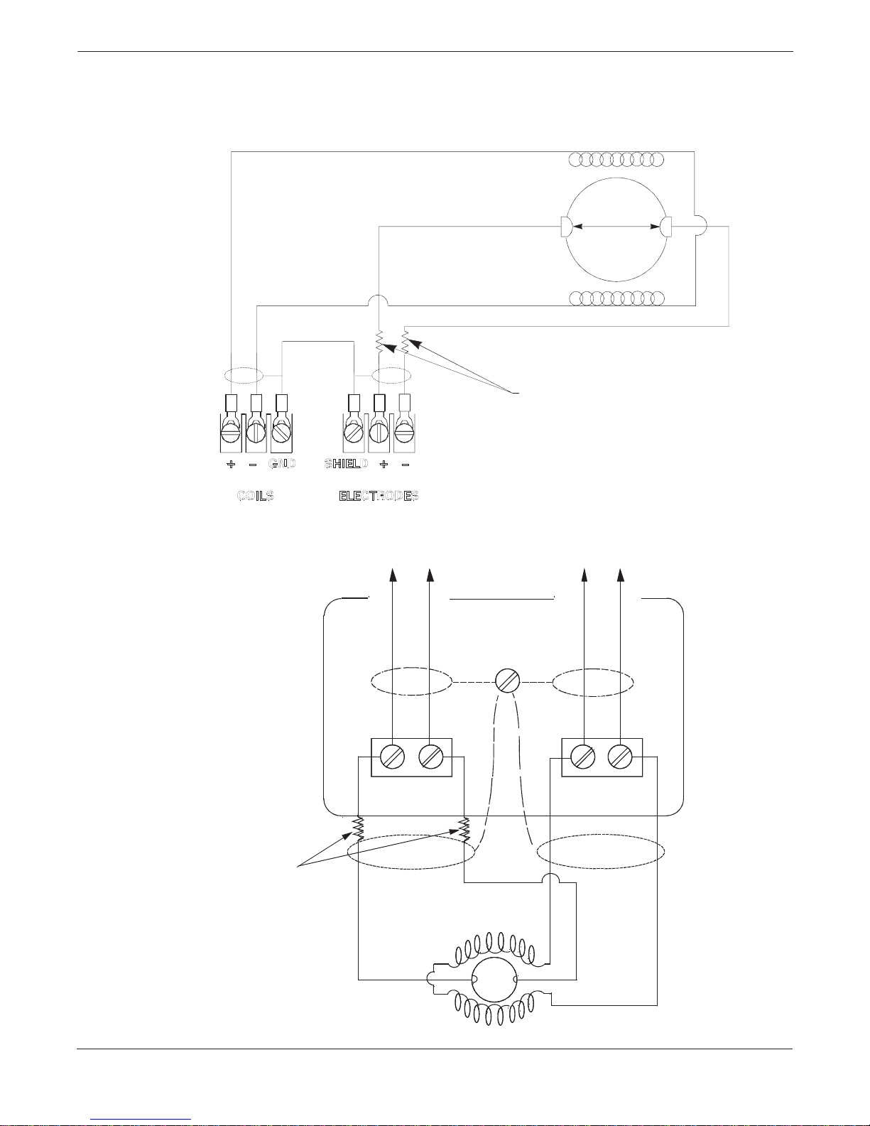
Rosemount Model 8732C Integral Mount Magnetic Flowmeter System
FIGURE 5-1. Model 8705
Flowtube Circuit Diagram.
Coil
Coil
To
Flowtube
Chassis
50 k
V both
FIGURE 5-2. Model 8711 Magnetic
Flowmeter Flowtube Circuit Diagram.
50 kV both
8705-0007E04A
to Transmitter to Transmitter
Shield
–+ –+
Electrodes Coil
5-6
8711-0371A
Page 73

Troubleshooting
RETURN OF MATERIALS
To expedite the return process outside the United States, contact the
nearest Rosemount representative.
Within the United States and Canada, call the North American
Response Center using the 800-654-RSMT (7768) toll-free number . This
center, available 24 hours a day, will assist you with any needed
information or materials.
The center will ask for product model and serial numbers, and will
provide a Return Material Authorization (RMA) number. The center
will also ask for the name of the process material to which the product
was last exposed.
Mishandling products exposed to a hazardous substance may result in
death or serious injury. If the product being returned was exposed to a
hazardous substance as defined by OSHA, a copy of the required
Material Safety Data Sheet (MSDS) for each hazardous substance
identified must be included with the returned goods.
The North American Response Center will detail the additional
information and procedures necessary to return goods exposed to
hazardous substances.
5-7
Page 74

Rosemount Model 8732C Integral Mount Magnetic Flowmeter System
5-8
Page 75

Section
6 Model 8732C Specifications
SPECIFICATIONS
and Reference Data
Functional Specifications
Flowtube Compatibility
Compatible with Rosemount Model 8705 or Model 8711 Flowtubes.
Flow Rate Range
Capable of processing signals from fluids that are traveling between
0.04 and 30 ft/s (0.01 to 10 m/s) for both forward and reverse flow in all
flowtube sizes. Full scale continuously adjustable between
–30 and 30 ft/s (–10 to +10 m/s).
Fluid Conductivity
Fluid must have conductivity of at least
5 microsiemen/cm.
Power Supply
90–250 V ac 50–60 Hz.
15– 50 V dc.
Power Consumption
10 watts maximum.
Ambient Temperature Limits
Operating
–40 to 165 °F (–40 to 74 °C).
Storage
–40 to 185 °F (–40 to 85 °C).
Output Signals
4–20 mA, switch-selectable as internally or externally powered;
0 to 1000 ohm load.
On the digital output terminals, a scalable frequency output is
available, 0 to 1000 Hz; transistor switch closure up to 5.75 W,
externally powered, 5 to 24 V ac or dc.
HART Communications, digital flow signal, superimposed on 4–20 mA
signal, available for control system interface. 250 ohms required for
HART Communications.
Analog Output Adjustment
Engineering units, lower and upper range values are user-selected.
Output automatically scaled to provide 4 mA at selected lower range
value, 20 mA at the selected upper range value. Full scale conti nuously
adjustable between –30 and +30 ft/s (–10 to +10 m/s), 1 ft/s (0.3 m/s)
minimum span. 4 mA also continuously adjustable.
Scalable Frequency Adjustment
Pulse Value
Value of one pulse can be set to equal desired volume in selected
engineering units.
Pulse Width
Adjustable from 0.5 to 100 ms. Local Operator Interface option
automatically calculates and displays maximum allowable
output frequency.
6-1
Page 76

Rosemount Model 8732C Integral Mount Magnetic Flowmeter System
Software Lockout
Security switch on electronics can be set for deactivation of all LOI
and HART-based communicator functions that affect the transmitter
input/output.
Auxiliary Output Function
In lieu of a scalable frequency output, an auxiliary output is available
using the digital output terminals. Transistor switch closure up to
5.75 W, externally powered, 5 to 24 V ac or dc, to indicate either:
Reverse Flow
Activates switch closure output when reverse flow is detected. The
reverse flow rate is displayed.
Zero Flo w
Activates switch closure output when flow goes to 0 ft/s.
Output Testing
Current Source
T ransmitter can be comman ded to supp ly a spec ified curre nt between
3.75 and 23.25 mA.
Frequency Source
Transmitter can be commanded to supply a specified frequency
between 1 and 1000 Hz.
Turn-on Time
30 minutes to rated accuracy from power up; 5 seco nds from power interrupti on.
Start-up Time
0.2 seconds from zero flow.
Low Flow Cutoff
Adjustable between 0.001 and 1 ft/s (0.003 and 0.3 m/s). Below selected
value, output is driven to the zero flow rate signal level.
Humidity Limits
0–100% RH to 150 °F (65 °C).
Overrange Capability
Signal output continues to 1 10% of upper range value setting, then
remains constant. Out of range message displayed on LOI
and the HART Communicator.
Damping
Adjustable between 0.2 and 256 seconds.
Flowtube Compensation
Rosemount flowtubes are flow-calibrated and assigned a calibration
factor at the factory. The calibration factor is entered into the
transmitter, enabling interchangeabi lity of flowtubes without
calculations or a compromise in accuracy.
6-2
Page 77

Model 8732C Specifications and Reference Data
Standard Hazardous Locations Certifications
Factory Mutual (FM) Approval
Approved for Class I, Division 2, Groups A, B, C, and D; Class II,
Division 1, Groups E, F, and G; Class III hazardous locations.
Canadian Standards Association (CSA) Approval
Approved for Class I Division 2, Groups A, B, C, and D; Class II,
Division 1, Groups E, F, and G; Class III hazardous locations.
Optional Hazardous Locations Certifications
FM Approval (E5)
Approved for Explosion-Proof Class I, Division 1, Groups C and D.
KEMA/CENELEC Approval (ED)
EEx d IIB T6.
Special Conditions
If the Magnetic Flowmeter T ransmitter Type 8732C is used integrally
with certified Magnetic Flowmeter Types 8705 or 8711, it shall
be assured that the mechanical contact areas of the 8705 or 8711
and the 8732C comply with the requirements for flanged joints,
EN 50018-1877, clause 4.1.
Performance
Specifications
(System specifications are given using the frequency output and with the unit at
reference conditions.)
Accuracy
With Model 8705 Flowtube:
System accuracy is ±0.5% of rate from 1 to 30 ft/s (0.3 to 10 m/s);
below 1.0 ft/s (0.3 m/s), the system has an accuracy of ±0.005 ft/s
(0.0015 m/s). Analog output has the same accuracy as frequency
output plus an additional 0.05% of span.
With Model 8711 Flowtube:
System accuracy is ±0.5% of rate from 3 to 30 ft/s (0.9 to 10 m/s);
below 3 ft/s (0.9 m/s), the system has an accuracy of ±0.015 ft/s
(0.045 m/s). Analog output has the same accuracy as frequency output
plus an additional 0.05% of span.
Repeatability
±0.1% of reading.
Response Time
0.2 seconds maximum response to step change in input.
Stability
±0.1% of rate over six months.
Ambient Temperature Effect
±0.25% change over operating temperature range.
EMC Compliance
Complies with the increased requirements from the NAMUR
Recommendations: May 1993, Part 1. Electromagnetic compatibility
(EMC) for process and laboratory apparatus.
Vibration Effect
Meets IEC 770 Pipeline Installation Conditions.
6-3
Page 78
Rosemount Model 8732C Integral Mount Magnetic Flowmeter System
Physical Specifications
ORDERING INFORMATION
Model Description
8732C Magnetic Flowmeter Transmitter
Code Transmitter Style
T Integral (mounted to Mode l 87 05, 8711 flowtubes)
Code Power Supply Voltage
12
03
Code Options
M4
(1)
C1
(2)
T1
L1
E5
ED
J1
J2
T ypical Model Number: 8732C T 12 M4
90–250 V ac, 50–60 Hz
15–50 V dc
Local Operator Interface
Custom Configurations
Non-volatile Totalizer
Transient Protection Circuitry
Factory Mutual (FM) Approvals, Class I. Division 1
KEMA/CENELEC Approvals, Group IIB
CM20 Conduit Adap te r s
PG13.5 Conduit Adapters
Electrical Connections
¾–14 NPT connections provided on the transmitter housing. PG13.5
and CM20 adapters are available. Screw terminals provided for all
connections. Power wiring connected to transmitter only. Integrally
mounted transmitters are factory wired to the flowtube.
Mounting
Transmitter is mounted integrally with the flowtube.
Materials of Construction
Housing
Low copper aluminum, NEMA 4X, CSA Type 4X, and IEC 529 IP66.
Paint
Polyurethane.
Cover Gasket
Rubber.
Weight
Approximately 7 pounds (3.2 kg). Add 1 pound (0.5 kg) for
the M4 option.
(1)
Custom Configuration (C1 Option)—When specifying custom configuration code C1, refer to Configuration Data Sheet 00806-0100-4668 and
provide the additional information as requested.
(2)
Non-volatile Totalizer—Non-volatile totalizer will retain totalizer data during power interruption. When power resumes, totalizing will continue.
6-4
t
Page 79
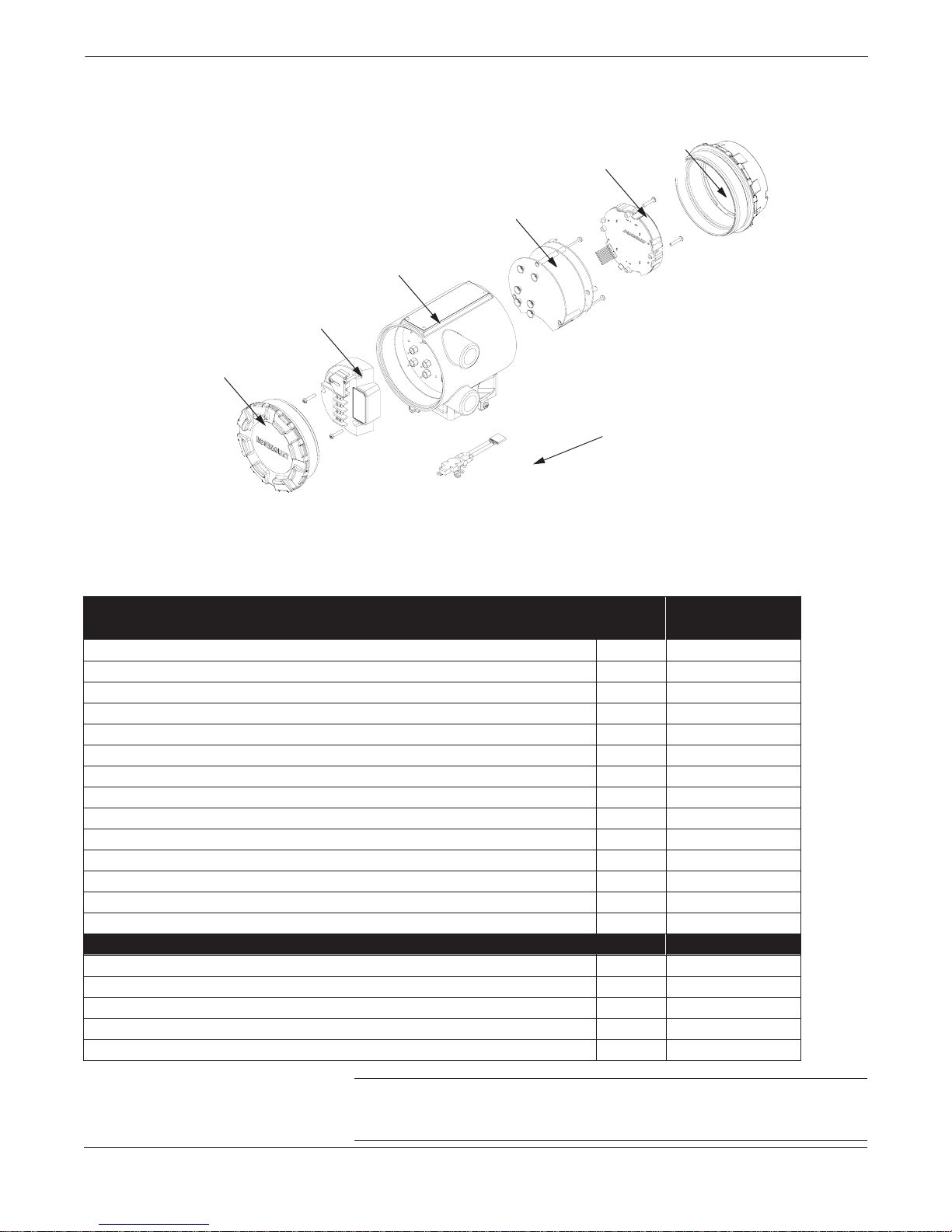
FIGURE 6-1. Model 8732C
Exploded Parts Drawing
Terminal Block Assembly
(Item #5, 6, 7, or 8)
Housing Cover
(Item #10)
Housing Assembly
(Item #9)
Three Board
Electronic Stack
(Items #1, 2, 3, or 4)
Model 8732C Specifications and Reference Data
LOI Cover
LOI Assembly
(Item #11)
(Item #12)
Electrical Connection
Assembly
(Item #13)
MODEL 8732C SPARE PARTS
Part Description
Model 8732C Electronics, 90–250 V ac (includes mounting hardware) 1 08732-0001-0001
Model 8732C Electronics with Non-volatile Totalizer, 90–250 V ac (includes mounting hardware) 2 08732-0001-0003
Model 8732C Electronics, 15-30V dc (Includes mounting hardware) 3 08732-0001-0002
Model 8732C Electronics with non-volatile totalizer, 15-30V dc (Includes mounting hardware) 4 08732-0001-0004
Standard Terminal Block Assembly (inclu des mountin g hardwa re) 5 087 32-0 002-00 01
Transient Protection Terminal Block Assembly (includes mounting hardware) 6 08732-0002-0002
DC Terminal Block Assembly (Includes mounting hardware) 7 08732-0002-0003
DC Transient Protection Terminal Block Assembly (Includes mounting ha rdwa re ) 8 08 73 2-0 0 02 -00 0 4
Integral Mount Housing Assembly (does not include terminal block assembly) 9 08732-0004-0001
Standard Housin g Cover (w it ho ut gla ss fo r LOI ) 10 087 3 2-0 0 05 -00 0 1
Local Operator Interfa ce (LOI ) Asse mbly (do e s not inclu d e LOI co ve r) 11 08732-0006-0002
LOI Cover 12 08732-0007-0002
Electrical Connection Assembly (Flowtube to transmitter) 13 08732-0133-0001
Model 8732C Non-Volatile Totalizer Chip – C53641-0003
Transmitter and Flowtube Accessories
Multi-Point Reference Calibration Standard (for use with Model 8712C, 8712U, or 8732C T ransmitters ) — Model 8714D
Spare Model 8714D Cable (for Model 8732C Transmitters) — 08714-0205-0001
UMB Tube to 8732C Transmitter Conversion Bracket — 08732-0160-0001
UMB Tube to 8732C Transmitter Conversion Cable (Three-pos ition cable assembly) — 08732-0161-0003
UMB Tube to 8732C Transmit te r Conversion Cable (Four-position cable assembly) — 08732-0161-0004
FIGURE 6-1. Model 8732C Exploded Parts Drawing.
Item
Number
Part Number
NOTE
When removing or replacing the transmitter housing, refer to
Transmitter Removal Procedure on page 5-5.
6-5
Page 80

Rosemount Model 8732C Integral Mount Magnetic Flowmeter System
6-6
Page 81

Section
7 Model 8705 Specifications
SPECIFICATIONS
and Reference Data
Functional Specifications
Service
Conductive liquids and slurries.
Line Sizes
½, 1, 1½, 2, 3, 4, 6, 8, 10, 12, 14, 16, 18, 20, 24, 30, and 36 inch
(15, 25, 40, 50, 80, 100, 150, 200, 250, 300, 350, 400, 450, 500, 600, 750,
and 900 mm).
Interchangeability
All Model 8705 Flowtubes and Series 8712 or 8732C Transmitters are
completely interchangeable. System accuracy is maintained regardless
of line size or optional features. Each flowtube nameplate has a multidigit calibration number that can be entered into any Series 8712 or
8732C Transmitter through the local operator interface (LOI) or the
HART Communicator. No further calibration is necessary.
Upper Range Limit
30 ft/s (10 m/s).
Process Temperature Limits
Special Conditions
At process temperatures > X °F (100 °C), the flowmeter must be used
with heat resistant cables with a temperature rating >
PTFE Teflon Lining
–20 to 350 °F (–29 to 177 °C).
ETFE Tefzel Lining
–20 to 300 °F (–29 to 149 °C).
Polyurethane Lining
0 to 140 °F (–18 to 60 °C).
Neoprene Lining
0 to 185 °F (–18 to 85 °C).
Natural Rubber Lining
0 to 185 °F (–18 to 85 °C).
Ambient Temperature Limits
–30 to 150 °F (–34 to 65 °C).
X °F (120 °C).
7-1
Page 82
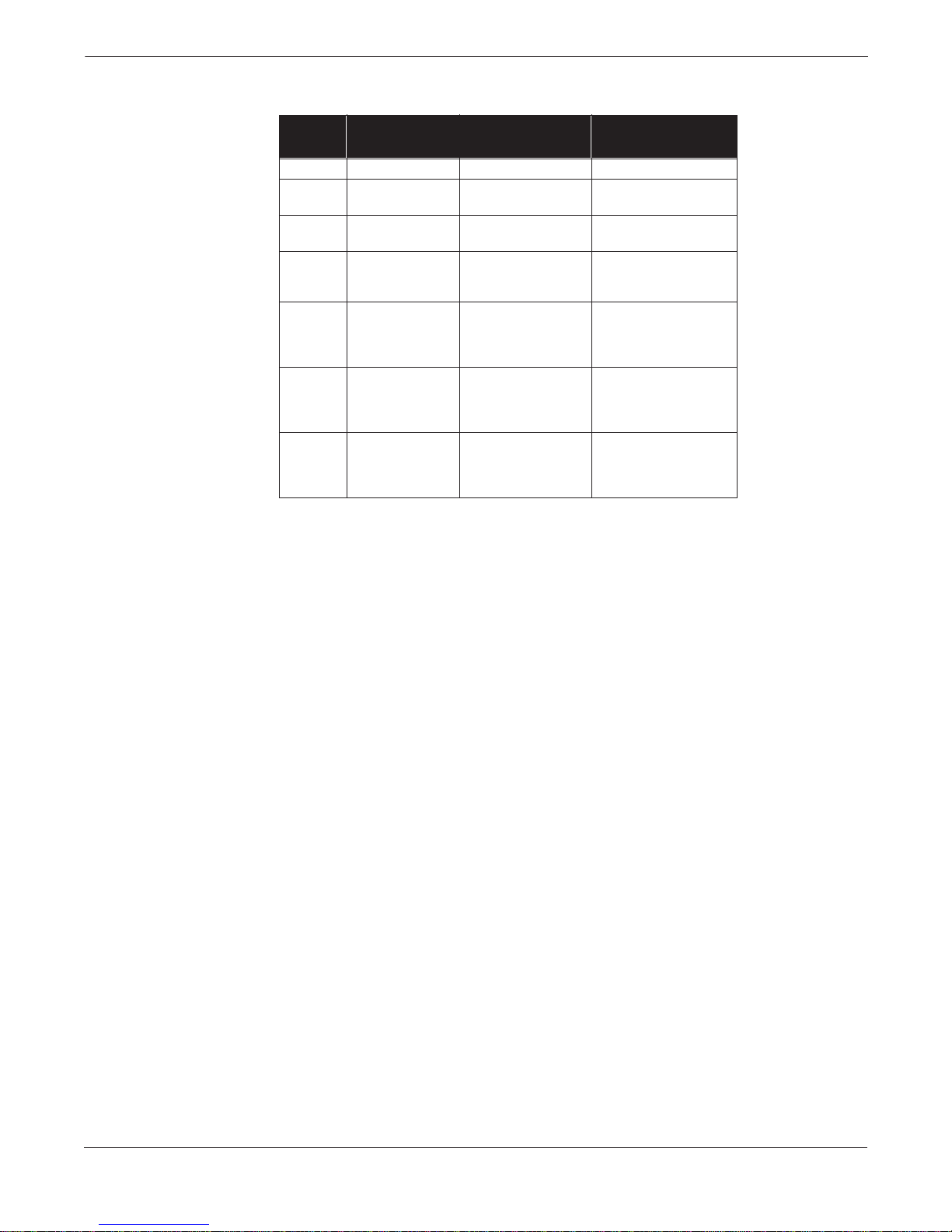
Rosemount Model 8732C Integral Mount Magnetic Flowmeter System
TABLE 7-1. Relation
Between Ambient
Temperature, Proces s
Temperature, and
Temperature Class.
Meter Size
(inches)
3 to 4
3 to 4
3 to 4
3 to 4
8 to 60
8 to 60
8 to 60
8 to 60
Maximum Ambient
T emperature
½ 149 °F (65 °C) 240 °F (116 °C) T3
1
1
1½
1½
2
2
2
6
6
6
6
149 °F (65 °C)
95 °F (35 °C)
149 °F (65 °C)
140 °F (60 °C)
149 °F (65 °C)
149 °F (65 °C)
104 °F (40 °C)
149 °F (65 °C)
149 °F (65 °C)
131 °F (55 °C)
104 °F (40 °C)
149 °F (65 °C)
149 °F (65 °C)
149 °F (65 °C)
140 °F (60 °C)
149 °F (65 °C)
149 °F (65 °C)
149 °F (65 °C)
149 °F (65 °C)
Maximum Process
T emperature
248 °F (120 °C)
95 °F (35 °C)
257 °F (125 °C)
140 °F (60 °C)
257 °F (125 °C)
167 °F (75 °C)
104 °F (40 °C)
266 °F (130 °C)
167 °F (75 °C)
194 °F (90 °C)
104 °F (40 °C)
175 °F (79 °C)
167 °F (75 °C)
230 °F (110 °C)
140 °F (60 °C)
284 °F (140 °C)
240 °F (116 °C)
176 °F (80 °C)
149 °F (65 °C)
Temperature Class
T3
T4
T3
T4
T3
T4
T5
T3
T4
T5
T6
T3
T4
T5
T6
T3
T4
T5
T6
Submergence Protection
Continuous to 30 feet (10 meters). IP 68.
Standard Hazardous Locations Certifications
Factory Mutual (FM) Approvals
Approved for Class I, Division 2, Groups A, B, C, and D; Class II, Division 1,
Groups E, F, and G; Class III hazardous locations.
NEMA 4X.
Canadian Standards (CSA) Approval
Approved for Class I, Division 2, Groups A, B, C, and D; Class II, Division 1,
Groups E, F, and G; Class III hazardous locations,
CSA enclosure 4.
Optional Hazardous Locations Certifications
KEMA/CENELEC
KD EEx e ia IIC T3...T6. See Table 7-1.
Conductivity Limits
Process liquid must have a conductivity of 5 microsiemens/cm (5 micromhos/cm)
or greater. Excludes the effect of interconnecting cable length in remote mount
transmitter installations.
Pressure Limits
See Table 7-2
.
7-2
Page 83
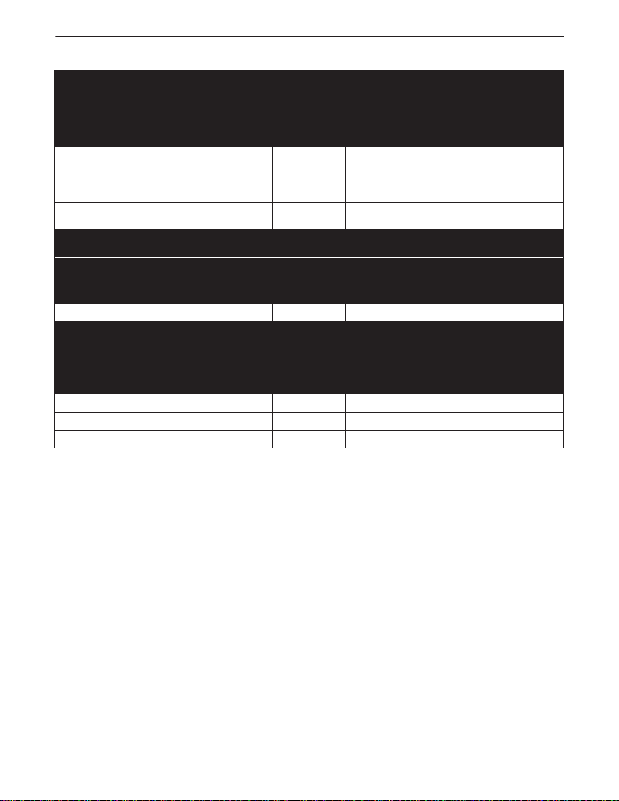
TABLE 7-2. Flowtube Temperature vs. Pressure Limits.
Model 8705 Specifications and Reference Data
ANSI Class Flanges: ½ – 24 inch Line Sizes
(1)
Pressure in psi
Flange Rating
Class 150
Carbon Stee l
Class 150
Stainless Steel
Class 300
Carbon Stee l
All
Liners
(@ 100 °F, 37.8
°C)
285 215 230 260 260 270
275 190 205 240 240 255
740 645 655 685 685 705
PTFE
Teflon
Liner
(@ 350 °F, 177
°C)
ETFE
Tefzel
Liner
(@ 300 °F, 149
°C)
Natural Rubber
Liner
(@ 185 °F, 85
°C)
Neoprene
Liner
(@ 185 °F, 85
°C)
Polyurethane
(@ 150 °F, 66
DIN Flanges: Line Sizes 15–80 mm
Pressure in Bars
All Liners
Flange Rating
(@ 100 °F, 37.8
°C)
PN 10–40 29.5 24.8 27.7 29.5 29.5 29.5
PTFE Teflon
Liner
(@ 350 °F, 177
°C)
ETFE
Tefzel
Liner
(@ 300 °F, 149
°C)
DIN Flanges: Line Sizes 100–600 mm
Natural Rubber
Liner
(@ 185 °F, 85
°C)
(1)
Neoprene
Liner
(@ 185 °F, 85
°C)
Polyurethane
(@ 150 °F, 66
Pressure in Bars
Flange Rating
All Liners
(@ 100 °F, 37.8
°C)
PTFE Teflon
Liner
(@ 350 °F, 177
°C)
ETFE
Tefzel
Liner
(@ 300 °F, 149
°C)
Natural Rubber
Liner
(@ 185 °F, 85
°C)
Neoprene
Liner
(@ 185 °F, 85
°C)
Polyurethane
(@ 150 °F, 66
Liner
°C)
Liner
°C)
Liner
°C)
PN 10 7.3 6.1 6.8 7.3 7.3 7.3
PN 16 11.8 9.9 11 11.8 11.8 11.8
PN 40 29.5 24.8 27.7 29.5 29.5 29.5
(1) Consult factory for larger line sizes.
Tefzel only available through 16” (400mm)
7-3
Page 84

Rosemount Model 8732C Integral Mount Magnetic Flowmeter System
Performance
Specifications
Physical
Specifications
(System specifications at reference conditions with frequency output and flowtube in new condition.)
Accuracy (with Model 8712C, Model 8712U or Model 8732C)
±0.5% of rate from 1 to 30 ft/s (0.3 to 10 m/s). Includes combined effects of
linearity, hysteresis, repeatability, and calibration uncertainty. Accuracy is
±0.005 ft/s (±0.0015 m/s) from low-flow cutoff to 1.0 ft/s (0.3 m/s).
Vibration Effect
Meets IEC 770 Pipeline Installation Conditions.
Mounting Position Effect
None when installed to ensure flowtube remains full.
Non-Wetted Materials
Flow Tube
AISI Type 304 SST.
Flanges
Carbon steel or AISI Type 304 SST.
Housing
Welded steel.
Paint
Polyurethane.
Process Wetted Materials
Lining
PTFE Teflon, ETFE Tefzel, polyurethane, neoprene, or natural rubber.
Electrodes
316L SST, Hastelloy C-276, tantalum, platinum-10% iridium, titanium.
Process Connections
AISI Type 304 SST – includes ANSI Class 150 flange to Tri-Clover Tri-Clamp
3-A quick-disconnect ferrule.
Process Connections
ANSI Class 150 or ANSI Class 300
½ through 24 inch.
AWWA Class 125
30- and 36-inch.
DIN PN 10, 16, 25, and 40
PN40 Standard Flange for 15–80 mm.
PN16 Standard Flange for 100–150 mm.
PN10 Standard Flange for 200–600 mm.
Electrical Connections
Two ¾–14 NPT connections are provided in the terminal enclosure for
electrical wiring.
Grounding Rings
Grounding rings are installed between the flange and the tube face on both ends
of the flowtube. They have an I.D. slightly larger than the flowtube I.D. and an
external tab to attach ground wiring. Grounding rings are available in 316L
stainless steel, Hastelloy C-276, titanium, and tantalum.
Grounding Electrode
A grounding electrode is installed similarly to the measurement electrodes
through the flowtube lining. It is available in 316L stainless steel,
Hastelloy C-276, titanium, tantalum or platinum.
Flowtube Dimensions
See Tables 7-3 and 7-4; Figures 7-1 and 7-2.
7-4
Page 85
Model 8705 Specifications and Reference Data
TABLE 7-3. Model 8705 Dimensions with ANSI Flanges in Inches (Millimeters).
Line Size
(1)
and Flange
Rating
0.5 inch–150 lb
0.5 inch–300 lb
1 inch–150 lb
1 inch–300 lb
1.5 inch–150 lb
1.5 inch–300 lb
2 inch–150 lb
2 inch–300 lb
3 inch–150 lb
3 inch–300 lb
4 inch–150 lb
4 inch–300 lb
6 inch–150 lb
6 inch–300 lb
8 inch–150 lb
8 inch–300 lb
10 inch–150 lb
10 inch–300 lb
12 inch–150 lb
12 inch–300 lb
14 inch–150 lb
14 inch–300 lb
16 inch–150 lb
16 inch–300 lb
18 inch–150 lb
18 inch–300 lb
20 inch–150 lb
20 inch–300 lb
24 inch–150 lb
24 inch–300 lb
30 inch–150 lb
36 inch–150 lb
Liner Face
Diameter
“A”
1.38 (35)
1.38 (35)
2.00 (51)
2.00 (51)
2.88 (73)
2.88 (73)
3.62 (92)
3.62 (92)
5.00 (127)
5.00 (127)
6.19 (157)
6.19 (157)
8.50 (216)
8.50 (216)
10.62 (270)
10.62 (270)
12.75 (324)
12.75 (324)
15.00 (381)
15.00 (381)
16.25 (413)
16.25 (413)
18.50 (470)
18.50 (470)
21.00 (533)
21.00 (533)
23.00 (584)
23.00 (584)
27.25 (692)
27.25 (692)
33.80 (859)
40.27 (1023)
Process
Flange
Rad. “B”
1.75 (44)
1.88 (48)
2.13 (54)
2.44 (62)
2.50 (64)
3.06 (78)
3.00 (76)
3.25 (83)
3.75 (95)
4.13 (105)
4.50 (114)
5.00 (127)
5.50 (140)
6.25 (159)
6.75 (171)
7.50 (191)
8.00 (203)
8.75 (225)
9.50 (241)
10.25 (260)
10.50 (267)
11.50 (292)
11.75 (298)
12.75 (324)
12.50 (318)
14.00 (356)
13.75 (349)
15.25 (387)
16.00 (406)
18.00 (457)
19.38 (492)
23.00 (584)
Overall
Flowtube
Length
(2)
“L”
7.88 (200)
7.88 (200)
7.88 (200)
7.88 (200)
7.88 (200)
7.88 (200)
7.88 (200)
7.88 (200)
7.88 (200)
8.63 (219)
9.84 (250)
10.88 (276)
11.81 (300)
13.06 (332)
13.78 (350)
15.60 (396)
15.00 (381)
17.13 (435)
18.00 (457)
20.14 (512)
21.00 (533)
23.25 (591)
24.00 (610)
26.25 (667)
27.00 (686)
30.12 (765)
30.00 (762)
33.25 (845)
36.00 (914)
39.64 (1007)
37.25 (946)
40.75 (1035)
Body
Height
“C”
8.75 (222)
8.75 (222)
8.75 (222)
8.75 (222)
9.52 (242)
9.52 (242)
9.52 (242)
9.52 (242)
11.52 (293)
11.52 (293)
12.22 (310)
12.22 (310)
14.39 (366)
14.39 (366)
16.33 (415)
16.33 (415)
19.11 (485)
19.11 (485)
21.27 (540)
21.27 (540)
23.39 (594)
23.39 (594)
25.41 (645)
25.41 (645)
27.93 (709)
27.93 (709)
29.95 (761)
29.95 (761)
34.50 (876)
34.50 (876)
40.41 (1026)
48.29 (1227)
(1) Consult factory for larger line sizes.
(2) When grounding rings (2 rings per meter) are specified, add 0.25 inch (6.35 mm) for ½- through 14-inch
(15 through 350 mm) flowtubes, 0.50 inch (12.7 mm) for 16-inch (400 mm) and larger. When lining
protectors are specified, add 0.25 inch (6.35 mm) for ½- through 12-inch (15 through 300 mm) flowtubes,
0.50 inch (12.7 mm) for 14- through 36-inch (350 through 900 mm) flowtubes.
Body
Widest’
with Port
“D”
6.88 (175)
6.88 (175)
7.34 (186)
7.34 (186)
7.05 (179)
7.05 (179)
7.47 (190)
7.47 (190)
9.57 (243)
9.57 (243)
10.01 (254)
10.01 (254)
10.41 (264)
10.41 (264)
11.38 (289)
11.38 (289)
17.00 (432)
17.00 (432)
19.16 (487)
19.16 (487)
21.28 (541)
21.28 (541)
23.30 (592)
23.30 (592)
25.82 (656)
25.82 (656)
27.84 (707)
27.84 (707)
32.39 (823)
32.39 (823)
38.50 (928)
46.38 (1178)
Centerline
to Conduit
“E”
5.16 (131)
5.16 (131)
5.16 (131)
5.16 (131)
5.57 (141)
5.57 (141)
5.57 (141)
5.57 (141)
6.57 (167)
6.57 (167)
6.92 (176)
6.92 (176)
8.05 (204)
8.05 (204)
9.02 (229)
9.02 (229)
10.44 (265)
10.44 (265)
11.52 (293)
11.52 (293)
12.58 (320)
12.58 (320)
13.59 (345)
13.59 (345)
14.85 (377)
14.85 (377)
15.86 (403)
15.86 (403)
18.14 (461)
18.14 (461)
21.31 (541)
25.25 (641)
Bolt Hole
Circle
Diameter
2.38 (60)
2.62 (67)
3.12 (79)
3.50 (89)
3.88 (99)
4.50 (114)
4.75 (121)
5.00 (127)
6.00 (152)
6.62 (168)
7.50 (191)
7.88 (200)
9.50 (241)
10.62 (270)
11.75 (298)
13.00 (330)
14.25 (362
15.25 (387)
17.00 (432)
17.75 (451)
18.75 (476)
20.25 (514)
21.25 (540)
22.50 (572)
22.75 (578)
24.75 (629)
25.00 (635)
27.00 (686)
29.50 (749)
32.00 (813)
36.00 (914)
42.75 (1086)
Bolt Hole
Diameter
0.62 (16)
0.62 (16)
0.62 (16)
0.75 (19)
0.62 (16)
0.88 (22)
0.75 (19)
0.75 (19)
0.75 (19)
0.88 (22)
0.75 (19)
0.88 (22)
0.88 (22)
0.88 (22)
0.88 (22)
1.00 (25)
1.00 (25)
1.12 (28)
1.00 (25)
1.25 (32)
1.12 (28)
1.25 (32)
1.12 (28)
1.38 (35)
1.25 (32)
1.38 (35)
1.25 (32)
1.38 (35)
1.37 (35)
1.62 (41)
1.38 (35)
1.63 (41)
Number
and Size
of Bolts
4–½
4–½
4–½
5
/8
4–
4–½
4–¾
5
4–
/8
8–5/8
4–5/8
8–¾
5
8–
/8
8–¾
8–¾
12–¾
8–¾
7
12–
/8
12–7/8
16–1
7
12–
/8
16–11/8
12–1
1
20–1
/8
16–1
20–1¼
1
16–1
/8
24–1¼
1
/8
20–1
24–1¼
20–1¼
24–1½
3
28–1
/8
32–1½
7-5
Page 86

Rosemount Model 8732C Integral Mount Magnetic Flowmeter System
TABLE 7-4. Flowtube Dimensions with DIN Flanges in Millimeters (Inches).
Overall
Flowtube
Length
(2)
“L”
Body
Height
“C”
Body
Width “D”
with Port
Centerline
to Conduit
“E”
Bolt Hole
Circle
Diameter
Bolt Hole
Diameter
Number of
Bolts
Rating
(1)
Liner Face
Diameter
“A”
Process
Flange
Rad. “B”
Line Size
and Flange
15 mm PN 10–40 45 (1.77) 47 (1.87) 200 (7.88) 222 (8.75) 175 (6.88) 131 (5.16) 65 (2.56) 14 (0.55) 4
25 mm PN 10–40 68 (2.68) 58 (2.27) 200 (7.88) 222 (8.75) 186 (7.34) 131 (5.16) 85 (3.35) 14 (0.55) 4
40 mm PN 10–40 88 (3.46) 75 (2.96) 200 (7.87) 242 (9.52) 179 (7.05) 141 (5.57) 110 (4.33) 18 (0.71) 4
50 mm PN 10–40 102 (4.02) 83 (3.25) 200 (7.87) 242 (9.52) 190 (7.47) 141 (5.57) 125 (4.92) 18 (0.71) 4
80 mm PN 10–40 138 (5.43) 100 (3.94) 200 (7.87) 293 (11.52) 243 (9.57) 167 (6.57) 160 (6.30) 18 (0.71) 8
100 mm PN 10–16 158 (6.22) 110 (4.33) 250 (9.84) 310 (12.22) 254 (10.01) 17 6 (6.92) 180 (7.09) 18 (0.71) 8
100 mm PN 25–40 162 (6.38) 117 (4.63) 250 (9.84) 310 (12.22) 254 (10.01) 176 (6.92) 190 (7.48) 22 (0.87) 8
150 mm PN 10–16 212 (8.35) 142 (5.61) 300 (11.81) 366 (14.39) 264 (10.41) 204 (8.05) 240 (9.45) 22 (0.87) 8
150 mm PN 25 218 (8.58) 150 (5.91) 300 (11.81) 366 (14.39) 264 (10.41) 204 (8.05) 240 (9.45) 22 (0.87) 8
150 mm PN 40 218 (8.58) 150 (5.91) 332 (13.06) 366 (14.39) 264 (10.41) 204 (8.05) 240 (9.45) 22 (0.87) 8
200 mm PN 10 268 (10.55) 170 (6.70) 351 (13.81) 415 (16.33) 289 (13.38) 229 (9.02) 295 (11.61) 22 (0.87) 8
200 mm PN 16 268 (10.55) 170 (6.70) 351 (13.81) 415 (16.33) 289 (13.38) 229 (9.02) 295 (11.61) 22 (0.87) 8
200 mm PN 25 278 (10.94) 180 (7.09) 350 (13.78) 415 (16.33) 289 (13.38) 229 (9.02) 310 (12.20) 26 (1.02) 12
200 mm PN 40 285 (11.22) 187 (7.38) 396 (15.60) 415 (16.33) 289 (13.38) 229 (9.02) 320 (12.60) 30 (1.18) 12
250 mm PN 10 320 (12.60) 197 (7.70) 381 (15.00) 485 (19.11) 432 (17.00) 265 (10.44) 350 (13.78) 22 (0.87) 12
250 mm PN 16 320 (12.60) 202 (7.97) 381 (15.00) 485 (19.11) 432 (17.00) 265 (10.44) 355 (13.98) 26 (1.02) 12
250 mm PN 25 335 (13.19) 213 (8.39) 381 (15.00) 485 (19.11) 432 (17.00) 265 (10.44) 370 (14.67) 30 (1.18) 12
250 mm PN 40 345 (13.58) 225 (8.86) 435 (17.13) 485 (19.11) 432 (17.00) 265 (10.44) 385 (15.16) 33 (1.30) 12
300 mm PN 10 370 (14.57) 223 (8.76) 457 (18.00) 540 (21.27) 487 (19.16) 265 (10.44) 400 (15.75) 22 (0.87) 12
300 mm PN 16 378 (14.88) 230 (9.06) 457 (18.00) 540 (21.27) 487 (19.16) 293 (11.52) 410 (16.14) 26 (1.02) 12
300 mm PN 25 395 (15.55) 242 (9.55) 457 (18.00) 540 (21.27) 487 (19.16) 293 (11.52) 430 (16.93) 30 (1.18) 16
300 mm PN 40 410 (16.14) 258 (10.12) 512 (20.14) 540 (21.27) 487 (19.16) 293 (11.52) 450 (17.72) 33 (1.30) 16
350 mm PN 10 430 (16.93) 252 (9.94) 534 (21.03) 594 (23.39) 541 (21.28) 293 (11.52) 460 (18.11) 22 (0.87) 16
350 mm PN 16 438 (17.24) 260 (10.24) 534 (21.03) 594 (23.39) 541 (21.28) 320 (12.58) 470 (18.50) 26 (1.02) 16
350 mm PN 25 450 (17.72) 277 (10.93) 534 (21.03) 594 (23.39) 541 (21.28) 320 (12.58) 490 (19.29) 33 (1.30) 16
350 mm PN 40 465 (18.31) 290 (11.42) 591 (23.25) 594 (23.39) 541 (21.28) 320 (12.58) 510 (20.08) 36 (1.42) 16
400 mm PN 10 482 (18.98) 282 (11.12) 610 (24.00) 645 (25.04) 592 (23.30) 345 (13.59) 515 (20.28) 26 (1.02) 16
400 mm PN 16 490 (19.29) 290 (11.42) 610 (24.00) 645 (25.04) 592 (23.30) 345 (13.59) 525 (20.67) 30 (1.18) 16
400 mm PN 25 505 (19.88) 310 (12.21) 610 (24.00) 645 (25.04) 592 (23.30) 345 (13.59) 550 (21.65) 36 (1.42) 16
400 mm PN 40 535 (21.06) 330 (12.99) 667 (26.25) 645 (25.04) 592 (23.30) 345 (13.59) 585 (23.03) 39 (1.54) 16
450 mm PN 10 532 (20.94) 308 (12.13) 686 (27.00) 709 (27.93) 656 (25.82) 377 (14.85) 565 (22.24) 26 (1.02) 20
450 mm PN 16 550 (21.65) 320 (12.60) 686 (27.00) 709 (27.93) 656 (25.82) 377 (14.85) 585 (23.03) 30 (1.18) 20
450 mm PN 40 560 (22.05) 343 (13.50) 765 (30.12) 709 (27.93) 656 (25.82) 377 (14.85) 610 (24.02) 30 (1.18) 20
500 mm PN 10 585 (23.03) 335 (13.19) 762 (30.00) 761 (29.95) 707 (27.84) 403 (15.86) 620 (24.41) 26 (1.02) 20
500 mm PN 16 610 (24.02) 358 (14.08) 762 (30.00) 761 (29.95) 707 (27.84) 403 (15.86) 650 (25.59) 33 (1.30) 20
500 mm PN 25 615 (24.21) 365 (14.37) 762 (30.00) 761 (29.95) 707 (27.84) 403 (15.86) 660 (25.98) 36 (1.42) 20
500 mm PN 40 615 (24.21) 378 (14.88) 845 (33.25) 761 (29.95) 707 (27.84) 403 (15.86) 670 (26.38) 42 (1.65) 20
600 mm PN 10 685 (26.97) 390 (15.36) 914 (36.00) 885 (34.85) 823 (32.39) 461 (18.14) 725 (28.54) 30 (1.18) 20
600 mm PN 16 725 (28.54) 420 (16.54) 914 (36.00) 877 (34.51) 823 (32.39) 461 (18.14) 770 (30.31) 36 (1.42) 20
600 mm PN 25 720 (28.35) 423 (16.64) 914 (36.00) 877 (34.51) 823 (32.39) 461 (18.14) 770 (30.31) 39 (1.54) 20
600 mm PN 40 735 (18.94) 445 (17.52) 1,007 (39.64) 886 (34.88) 823 (32.39) 461 (18.14) 795 (31.30) 48 (1.88) 20
(1) Consult factory for larger line sizes.
(2) When grounding rings (2 rings per meter) are specified, add 6.35 mm (0.25 in.) for 15 mm through 350 mm (½- through 14 in.) flowtubes or
12.7 mm (0.50 in.) for 400 mm (16 in.) and larger. When lining protect ors are specif ied, add 6.35 mm (0.25 in.) for 15 mm through 300 mm
(½- through 12-in.) flowtubes, 12.7 mm (0.50 in.) for 350 mm through 900 mm (14- through 36-in.) flowtubes.
7-6
Page 87
TABLE 7-5. Flowtube Dimensions with ANSI Flanges and
Tri-Clamp Adaptors (A3) in Inches (Millimeters)
Model 8705 Specifications and Reference Data
T ABLE 7-6. Flowtube Weight
Line Size
and
Flange
Rating
0.5–150 lb. 1.00 (25) 1.75 (44) 8.38 (213) 5.16 (131) 13.78 (350)
1–150 lb. 1.50 (40) 2.13 (54) 8.38 (213) 5.16 (131) 13.78 (350)
1.5–150 lb. 2.00 (50) 2.50 (64) 9.00 (229) 5.56 (141) 13.78 (350)
2–150 lb. 3.00 (80) 3.00 (76) 9.00 (229) 5.56 (141) 13.78 (350)
3–150 lb. 4.00 (100) 3.75 (95) 12.00 (305) 6.57 (167) 13.78 (350)
Nominal Line Size
Inches (mm)
Nominal
Clamp
Diameter
½ (15)
½ (15)
1 (25)
1 (25)
1½ (40)
1½ (40)
2 (50)
2 (50)
3 (80)
3 (80)
4 (100)
4 (100)
6 (150)
6 (150)
8 (200)
8 (200)
10 (250)
10 (250)
12 (300)
12 (300)
14 (350)
16 (400)
18 (450)
20 (500)
24 (600) 150 PN 10 1,000 (454)
30 (750)
36 (900)
Tri-
Process
Flange
Rad. “B”
Flowtube Flange
(1)
ANSI DIN
150
300
150
300
150
300
150
300
150
300
150
300
150
300
150
300
150
300
150
300
150
150
150
150
125
125
Body
Height
Centerline
to Conduit
“C” Max
Rating
PN 40
PN 40
PN 40
PN 40
PN 40
PN 16 48 (22)
PN 16 81 (37)
PN 10 110 (50)
PN 10 220 (98)
PN 10 330 (150)
PN 10
PN 10
PN 10
PN 10
PN 10
PN 10
Flowtube
“E”
Flowtube Weight
lb (kg)
20 (9)
22 (10)
20 (9)
22 (10)
22 (10)
24 (11)
26 (12)
28 (13)
40 (18)
47 (21)
65 (30)
93 (42)
162 (74)
300 (136)
435 (197)
370 (168)
500 (227)
600 (272)
680 (308)
1,400 (637)
1,975 (898)
Overall
Length
“L”
(1) Consult factory for larger line sizes.
7-7
Page 88
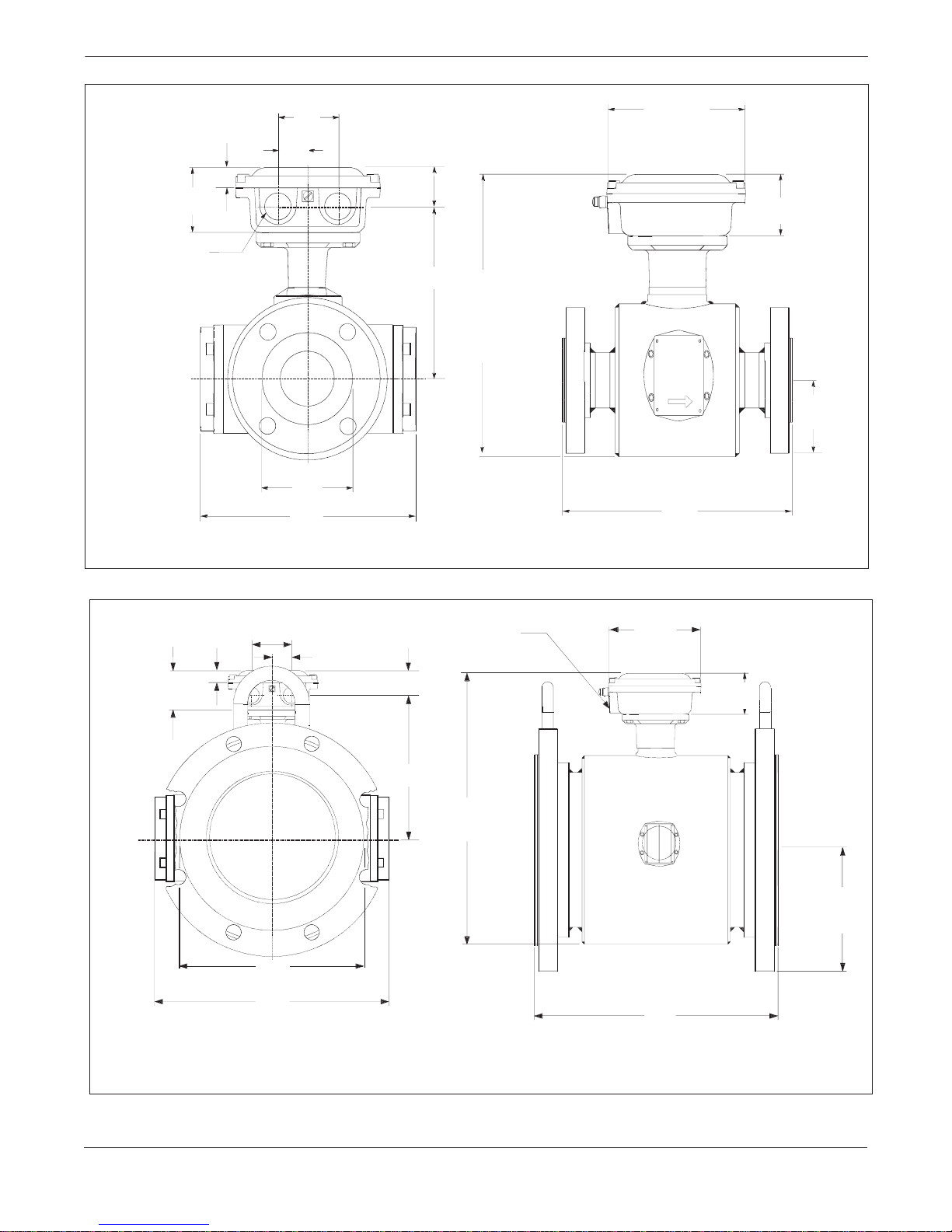
Rosemount Model 8732C Integral Mount Magnetic Flowmeter System
0.66
(17)
2.00
(51)
1.00
(25)
1.35
(34)
4.75
(121)
2.00
(51)
¾–14 NPT Conduit
Connection
“E”
“C”
“A”
“D”
NOTES
Dimensions are in inches (millimeters ).
See Table 7-3 and 7-4 for variable dimensions.
“L”
FIGURE 7-1. Dimensional Drawing of Model 8705 Flowtubes, Typical of ½- throug h 4-inc h (15–1 00 mm) Line Sizes .
2.00
(51)
“B”
8705-1002A05A, 1002B05A1
2.00
(51)
0.66
(17)
2.00
(51)
1.00
(25)
1.35
(34)
¾–14 NPT
Conduit
Connection
4.75
(121)
2.00
(51)
“E”
“C”
“A”
“D”
“L”
NOTES
Dimensions are in inches (millimeters).
Consult factory for larger line sizes.
See Table 7-3 and 7-4 for variable dimensions.
FIGURE 7-2. Dimensional Drawing of Model 8705 Flowtubes, Typical of 6- through 36-inch (150–900 mm) Line Sizes.
“B”
8705-1002A06A, 1002B06A
7-8
Page 89
Model 8705 Specifications and Reference Data
ORDERING INFORMATION
Model Product Description
8705 Magnetic Flowmeter Flowtube
Code Lining Material
T
F
P
N
G
Code Electrode Material Code A (Add) Code E (Add) Code R (Add)
S
H
T
P
N
Code Electrode Type
A
E
R
PTFE
T eflon
ETFE
Tefzel
Polyurethane
Neoprene
Natural Rubber
Available in 1½- through 36-inch (40–900 mm) line sizes.
ELECTRODE TYPE (see below)
316L Stainless Steel
Hastelloy C-276
Tantalu m
Platinum – 10% Iridium
Titanium
Standard, Two Measurement Electrod e s
Two Measurement Electrodes plus Third Grounding Electrode
Two Field-removable Electrodes (Electrode Material Codes S and H only.) (Not available in ½- and 1-inch (13-25mm) line sizes.) On
1½- to 4-inch (40 to 100 mm), fi eld removable e lectrodes are no t ava ilable with sealed electrode compartments. Access only available.
Available with PTFE lining only.
•
•
•
•
•
•
•
•
•
•
LINING MATERIAL
•
•
—
—
—
Code Line Size
005
010
015
020
030
040
060
080
100
120
140
160
180
200
240
300
360
½ inch (15 mm)
1 inch (25 mm)
1½ inch (40 mm)
2 inch (50 mm)
3 inch (80 mm)
4 inch (100 mm)
6 inch (150 mm)
8 inch (200 mm)
10 inch (250 mm)
12 inch (300 mm)
14 inch (350 mm)
16 inch (400 mm)
18 inch (450 mm)
20 inch (500 mm)
24 inch (600 mm)
30 inch (750 mm)
36 inch (900 mm)
PTFE
Code Flange Material, Type and Rating
C1
C3
S1
S3
CD
CE
CF
CH
SD
SE
SF
SH
Carbon Steel, ANSI Class 150 (AWWA Class 125–30 and 36 inch)
Carbon Steel, ANSI Class 300
304 Stainless Steel, ANSI Class 15 0 (AWWA Class 125–30 and 36 inch)
304 Stainless Steel, ANSI Class 30 0
Carbon Steel, DIN PN 10 (Standard size flan g e for sizes 20 0 thro ugh 900 m m)
Carbon Steel, DIN PN 16 (Standard size flang e for sizes 100 and 150 mm)
Carbon Steel, DIN PN 25
Carbon Steel, DIN PN 40 (Standard size flang e for sizes 15 throu gh 80 mm)
Stainless Steel, DIN PN 10 (Sta nda rd size flan ge for sizes 20 0 throu g h 900 mm)
Stainless Steel, DIN PN 16 (Sta nda rd size flan ge for sizes 10 0 and 150 mm )
Stainless Steel, DIN PN 25
Stainless Steel, DIN PN 40 (Standard size flange for sizes 15 through 80 mm)
Code T
Teflon
•
•
•
•
•
•
•
•
•
•
•
•
•
•
•
•
•
Code F
ETFE
Tefzel
•
•
•
•
•
•
•
•
•
•
•
•
—
—
—
—
—
Code P
Polyurethane
—
—
•
•
•
•
•
•
•
•
•
•
•
•
•
•
•
Code N
Neoprene
—
—
•
•
•
•
•
•
•
•
•
•
•
•
•
•
•
Code G
Natural
Rubber
—
—
•
•
•
•
•
•
•
•
•
•
•
•
•
•
•
7-9
Page 90

Rosemount Model 8732C Integral Mount Magnetic Flowmeter System
Code Optional Grounding Rings and Lining Protection
G
L
Code Grounding Rings, Lining Protecto r Wetted Material
1
2
3
4
Code Options
W1
H1
B1
B3
KD
Q4
Q5
Q8
Q9
A3
T ypical Model Number: 8705 T S A 040 C1 G 1
(1) W1 is shipped with a 5 psi housing relief valve.
(2) Teflon (T) liner only. W1 option required. Only Stainless Steel Tri-Clamp Adapters available. Available with
Stainless Steel, Hastelloy, and Platinum – 10% Iridium type electrodes.
Grounding Ring
Lining Prote cto r s
316L SST
Hastelloy C-276
Titanium (Available in ½-through 12-inch (15 - 300mm) sizes only.)
Tantalum (Available in ½- through 8-inch (15 - 200 mm) sizes only.) (Not available with option code L.)
Standard sealed, welded housing without sealed electrode compartments
Not available with field-removable electrodes (Option Code R)
Flowtube with Model 8701 lay length (Available for ½ throug h 16-in ch (15 – 400 mm) line sizes)
(For ½ through 4-inch (15–100 mm) sizes, the flowtu b e is shipped wit h a spool piece )
Integral Mount with Model 8712C Transmitter
Integral Mount with Model 8732C Transmitter
KEMA/CENELEC Approval
Calibration Data Sheet
Hydrostatic Test Certificate
Material Traceability Certificate per DIN 3.1B
Material Traceability Certificate (Electrod e s only) per DIN 3. 1B
Sanitary 3-A for ANSI 150 to Tri-Clamp (½- to 3-inches (15-80 mm) sizes only)
Grounding rings and lining protectors cannot be used together.
}
Both options provide the same fluid groundin g fun ction.
Lining protectors available with PTFE liners only .
(Available in ½-through 12-inch (15 - 300mm) sizes only.)
(1)
(2)
7-10
Page 91
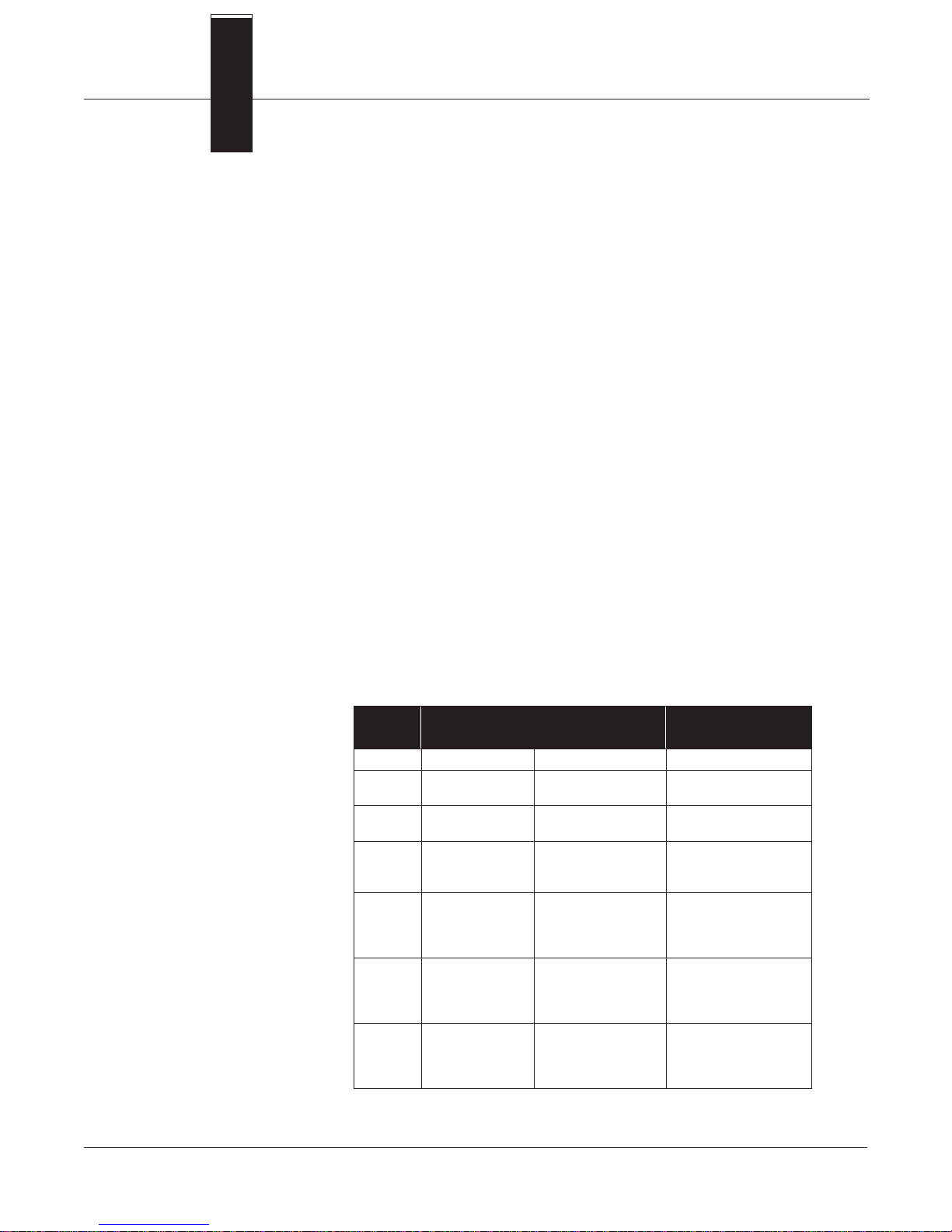
Section
8 Model 8711 Specifications
SPECIFICATIONS
and Reference Data
Functional Specifications
T ABLE 8-1. Relation Be tween Ambient
Temperature, Proces s Temperature,
and Temperature Class.
Service
Conductive liquids and slurries.
Line Sizes
0.15, 0.30, 0.5, 1, 1.5, 2, 3, 4, 6, and 8 inches (4, 8, 15, 25, 40, 50, 80, 100,
150, 200 mm).
Upper Range Limit
30 ft/s (10 m/s).
Interchangeability
All Model 8711 Flowtubes and Series 8712 or 8732 Transmitters are
interchangeable. Each flowtube nameplate has a multi-digit calibration
number that can be entered into any Series 8712 or 8732 Transmitter
through the Local Operator Interface (LOI) or a HART-based
communicator. No further calibration is necessary.
Process Temperature Limits
ETFE Tefzel Lining
–20 to 300 °F (–29 to 149 °C) for ½ through 8-inch (15–200 mm)
line sizes.
–20 to 200 °F (–29 to 93 °C) for 0.15 and 0.3-inch
(4 and 8 mm) line sizes.
Meter Size
(inches)
3 to 4
3 to 4
3 to 4
3 to 4
8 to 60
8 to 60
8 to 60
8 to 60
Maximum Ambient
T emperature
½ 149 °F (65 °C) 240 °F (116 °C) T3
1
1
1½
1½
2
2
2
6
6
6
6
149 °F (65 °C)
95 °F (35 °C)
149 °F (65 °C)
140 °F (60 °C)
149 °F (65 °C)
149 °F (65 °C)
104 °F (40 °C)
149 °F (65 °C)
149 °F (65 °C)
131 °F (55 °C)
104 °F (40 °C)
149 °F (65 °C)
149 °F (65 °C)
149 °F (65 °C)
140 °F (60 °C)
149 °F (65 °C)
149 °F (65 °C)
149 °F (65 °C)
149 °F (65 °C)
Maximum Process
T emperature
248 °F (120 °C)
95 °F (35 °C)
257 °F (125 °C)
140 °F (60 °C)
257 °F (125 °C)
167 °F (75 °C)
104 °F (40 °C)
266 °F (130 °C)
167 °F (75 °C)
194 °F (90 °C)
104 °F (40 °C)
175 °F (79 °C)
167 °F (75 °C)
230 °F (110 °C)
140 °F (60 °C)
284 °F (140 °C)
240 °F (116 °C)
176 °F (80 °C)
149 °F (65 °C)
Tempe rature Cl as s
T3
T4
T3
T4
T3
T4
T5
T3
T4
T5
T6
T3
T4
T5
T6
T3
T4
T5
T6
8-1
Page 92

Rosemount Model 8732C Integral Mount Magnetic Flowmeter System
Standard Hazardous Locations Certifications
Factory Mutual (FM) Approval
Approved for Class I, Division 2, Groups A, B, C, and D; Class II, Division 1,
Groups E, F, and G; Class III hazardous locations.
NEMA 4X.
Canadian Standards Association (CSA) Approval
Approved for Class I, Division 2, Groups A, B, C, and D; Class II, Division 1,
Groups E, F, and G; Class III hazardous locations,
CSA enclosure 4.
Optional Hazardous Locations Certifications
E5 Factory Mutual (FM) Approval
Explosion Proof for Class I, Division 1, Groups C and D.
Available for remote mount Series 8712 or integral mount
8732C Transmitters.
KEMA/CENELEC Approval
CD EEx e ia IIC T3...T6. See Table 8-1.
Maximum Safe Working Pressure at 100 °F (38 °C)
Tefzel Lining
Full vacuum to 740 psi (5.1 MPa) for ½ through 8-inch
(15–200 mm) flowtubes.
285 psi (1.96 MPa) for 0.15- and 0.30-inch (4 and 8 mm) flowtubes.
Performance
Specifications
Physical
Specifications
(System specifications are given using the frequency output and with the unit at referenced conditions.)
Accuracy (with Model 8712C/U or Model 8732C Transmitters)
±0.5% of rate from 3 to 30 ft/s (1 to 10 m/s).
±0.015 ft/s (0.005 m/s) from low-flow cutoff to
3 ft/s (1 m/s).
Vibration Effect
Meets IEC 770 Pipeline Installation Conditions.
Mounting Position Effect
No effect when installed to ensure flowtube remains full.
Non-Wetted Materials
Flowtube
303 SST (ASTM A-743).
Coil Housing
Investment cast steel (ASTM A-27).
Paint
Polyurethane.
Process-Wetted Materials
Lining
Tefzel.
Electrodes
316L SST, titanium, tantalum, Hastelloy C-276,
or platinum—10% iridium.
8-2
Page 93
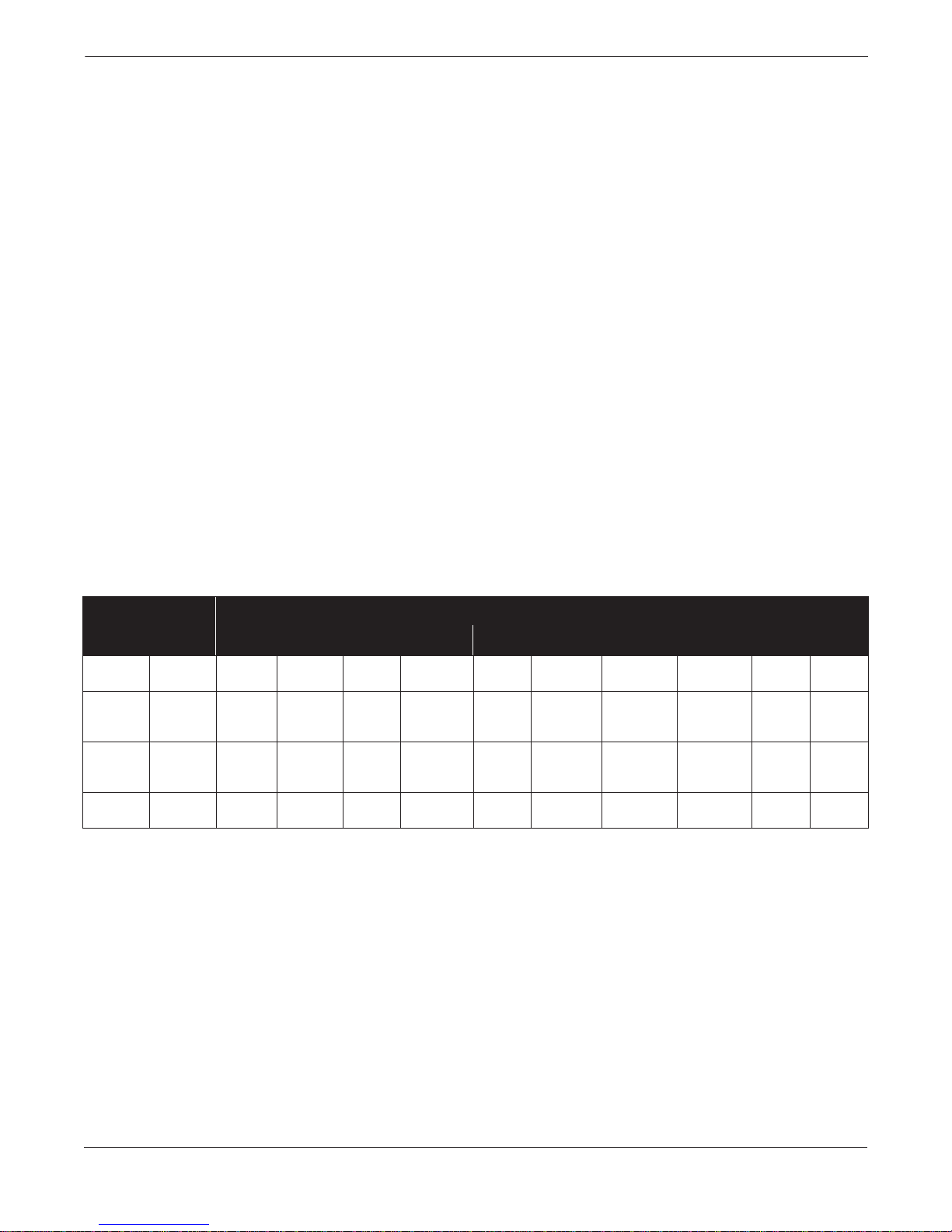
Model 8711 Specifications and Reference Data
Process Connections
Mounts between these Flange Configurations
ANSI: Class 150, 300.vv
DIN: PN 10 and 25.
BS: 10 Table D, E, and F.
Mounting Studs
0.15, 0.30, 0.5, and 1 inch (4, 8, 15, 25 mm):
316 SST, ASTM A-193, Grade B7.
1.5, 2, 3, 4, 6, and 8 inch (40, 50, 80, 100, 150 and 200 mm):
CRS, ASTM A-193, Grade B7.
Electrical Connections
Two ¾–14 NPT connections are provided in the terminal enclosure for
electrical wiring.
Grounding Rings
Grounding rings are installed between the flange and the tube face on
both ends of the flowtube. They have an ID slightly larger than the flowtube
ID and an external tab for attaching ground wiring. Grounding rings are available
in 316L stainless steel, Hastelloy C-276, titanium, and tantalum.
Grounding Electrode
A grounding electrode is installed similarly to the measurement
electrodes through the flowtube lining. It is available in 316L stainless steel,
Hastelloy C-276, titanium, tantalum or platinum.
Weight
See Table 8-2.
TABLE 8-2. Flowtube Dimensions and Weight.
Nominal
Line Size
Inches (mm)
(1)
0.15
(1)
0.30
0.5
1
1.5
2
3
4
6
8
(4)
(8)
(15)
(25)
(40)
(50)
(80)
(100)
(150)
(200)
“A” Max. “B” “C”
5.85
5.85
5.85
6.16
6.16
6.47
7.09
7.78
8.81
9.87
(1) 0.15 and 0.30 inch (4 and 8 mm) flowtubes mount between ½-inch (13 mm) flange.
Flowtube Housing Dimensions Flowtube Length
(149)
(149)
(149)
(157)
(157)
(165)
(180)
(198)
(224)
(251)
6.79
6.79
6.79
7.41
7.30
7.91
9.14
10.53
12.59
14.72
(172)
(172)
(172)
(188)
(185)
(201)
(232)
(267)
(320)
(374)
3.56
3.56
3.56
4.50
3.25
3.88
5.13
6.50
8.56
10.69
(90)
(90)
(90)
(114)
(83)
(99)
(130)
(165)
(218)
(272)
2.15
2.15
2.15
2.15
2.73
3.26
4.68
5.88
6.87
8.86
“D”
(55)
(55)
(55)
(55)
(69)
(83)
(119)
(149)
(175)
(225)
4
4
4
5
5
7
13
22
35
60
Weight
lb (kg)
(2)
(2)
(2)
(2)
(2)
(3)
(6)
(10)
(16)
(27)
8-3
Page 94
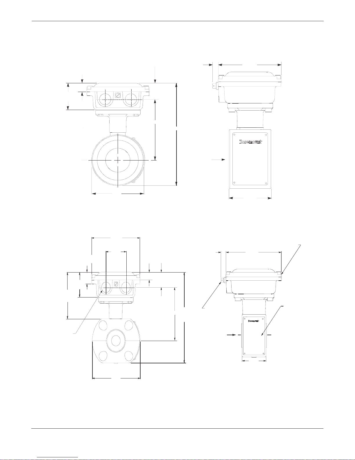
Rosemount Model 8732C Integral Mount Magnetic Flowmeter System
FIGURE 8-1. Model 8711
Dimensional Drawings
1.5- THROUGH 8-INCH LINE SIZES
2.00
(51)
0.66
(17)
1.35
(34)
“A”
“B”
“C”
0.15- THROUGH 1-INCH LINE SIZES
0.5
(13)
4.75
(121)
Flow
“D”
0.87
(22)
2.00
(51)
3.37
(86)
¾–14 NPT
Conduit
Connection
(2 places)
NOTES
Dimensions are in inches (millimeters).
See Table 8-2 for variable dimensions.
4.75
(121)
2.00
(51)
“C”
0.66
(17)
1.35
(34)
“A”
“B”
0.50
(13)
Grounding
Clamp
Flow
Wiring Connection
Cover
4.75
(121)
Nameplate
“D”
8711-1012B04A, A04A, B03A, A03A
8-4
Page 95

ORDERING INFORMATION
Model Product Description
8711 Magnetic Flowme te r Flowtu b e (Flang e less Cons tru ctio n)
Code Lining Material
T
Code Electrode Material
S
H
T
P
N
Code Electrode Construction
A
E
Code Line Size, Inches (mm)
15F
30F
005
010
015
020
030
040
060
080
Code Transmitter Mounting Configuration
R
S
U
Code Mounting Kit
1
2
3
4
Code Option
E5
G1
G2
G3
G4
CD
Q4
Q8
Q9
Typical Model Number: 8711 T S A 040 R 1 G1
ETFE Tefz el
316L SST
Hastelloy C-276
Tantalum
Platinum – 10% Iridium
Titanium
Standard Measurement Electrodes (no gro un d ing ele ctrode)
Measurement Electrodes and Grounding Electrode
0.15 (4)
0.30 (8)
0.5 (15)
1.0 (25)
1.5 (40)
2.0 (50)
3.0 (80)
4.0 (100)
6.0 (150)
8.0 (200)
Remote (2-inch Pipe or Surface Mou nt )
Integral with Model 8712C Transmitter
Integral with Model 8732C Transmitter
ANSI Class 150
DIN PN 10/16 (8 inch (200mm) has a PN 10 Mounting Kit Only.)
ANSI Class 300
DIN PN 25/40 (8 inch (200mm) has a PN 25 Mounting Kit Only.)
Factory Mutual (FM) Explosion Proof Approvals
Grounding Rings, 316L SST
Grounding Rings,
Grounding Rings, Titanium
Grounding Rings, Tantalum
KEMA/CENELEC Flameproof Approvals
Calibration Data Sh ee t
Material Traceability Certificate per DIN 3.1B
Material Traceability Certificate (Electrode s only) pe r DIN 3.1B
Hastelloy C-276
Model 8711 Specifications and Reference Data
8-5
Page 96

Rosemount Model 8732C Integral Mount Magnetic Flowmeter System
8-6
Page 97
Appendix
A HART Communicator
INTRODUCTION
SAFETY MESSAGES
This appendix provides basic communicator information on the HART
Communicator Model 275 when used with a Model 8732C Integral
Mount Magnetic Flowmeter System.
Included in this appendix are a menu tree, a table of fast key sequences,
and information on using the HART communicator.
For more complete information on the HART Communicator, refer to
the HART Communicator Product Manual 00809-0100-4275.
This brief appendix will familiarize you with the HART Communicator
but is not meant to replace the HART Communicator product manual.
Instructions and procedures in this section may require special
precautions to ensure the safety of the personnel performing the
operations. Please read the following safety messages before
performing any operation described in this section.
Explosions could result in death or serious injury:
• Verify that the operating atmosphere of the flowtube and transmitter is
consistent with the appropriate hazardous locations certifications.
• Do not remove the transmitter cover in explosive atmospheres
when the circuit is alive.
• Before connecting a HART-based communicator in an explosive
atmosphere, make sure the instruments in the loop are
installed in accordance with intrinsically safe or non-incendive field
wiring practices.
• Do not make connections to the HART Communicator’s serial port or
NiCad recharger jack in an explosive atmosphere.
• Both transmitter covers must be fully engaged to meet
explosion-proof requirements.
Failure to follow safe installation and servicing guidelines could result in
death or serious injury:
• Make sure only qualified personnel perform these procedures.
• Do not perform any service other than those contained in this manual
unless qualified.
A-1
Page 98
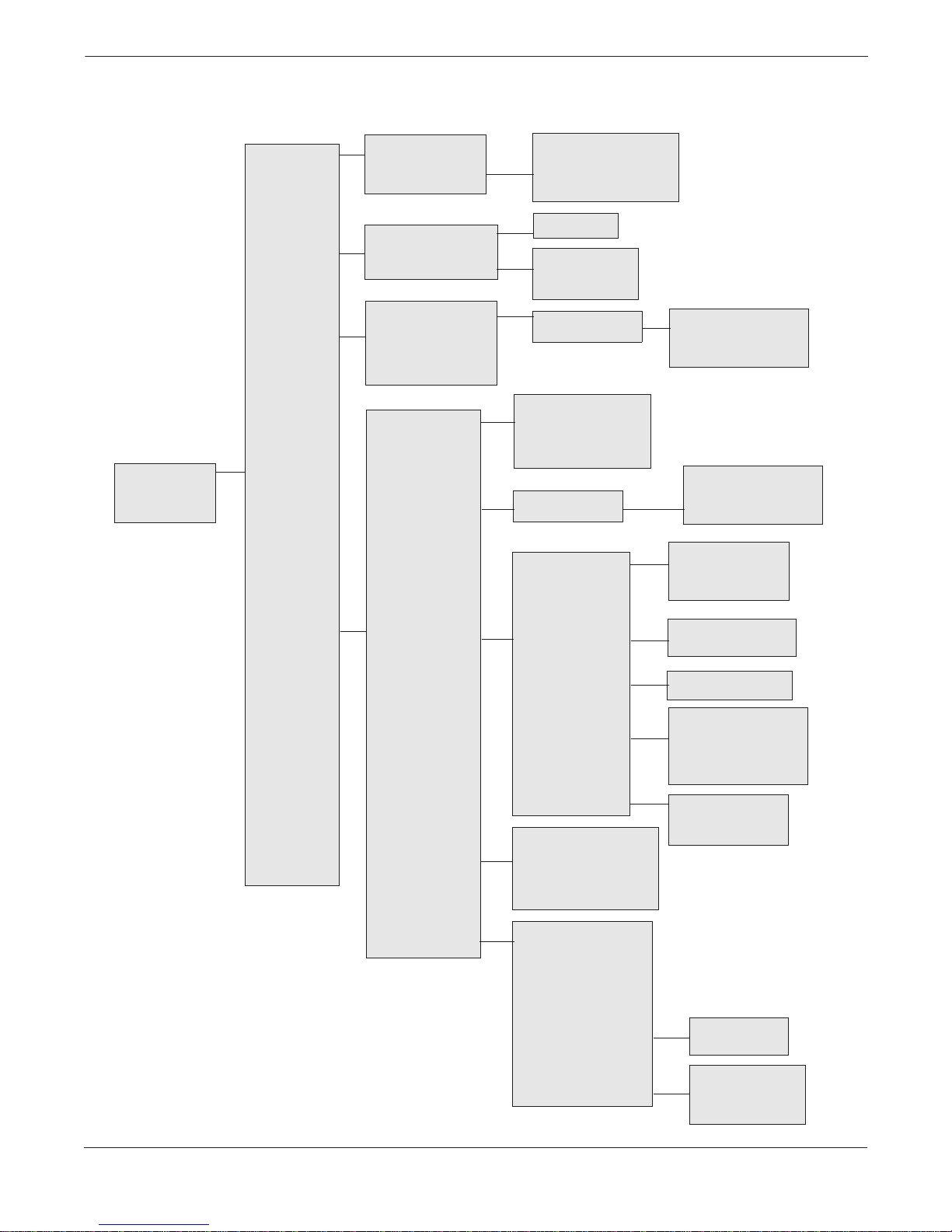
Rosemount Model 8732C Integral Mount Magnetic Flowmeter System
FIGURE A-1. HART Communicator Menu T ree .
On-line Menu
1 DEVICE SETUP
2 PV
3 AO
4 LRV
5 URV
1 PROCESS
VARIABLE
2 DIAGNOSTICS
& SERVICE
3 BASIC SETUP
4 DETAILED
SETUP
1 Flow Rate
2 Percent of Range
3 Analog Output
4 TOTALIZER
5 Pulse Output
1 SELF TEST/STATUS
2 Loop Test
3 Pulse Output Test
4 CALIBRATION
1 Tag
2 PV UNITS
3 Upper Range Value
4 Lower Range Value
5 Line Size
6 Calibration Number
7 Damping
1 CHARACTERIZE
METER
2 PV UNITS
3 CONFIGURE
OUTPUTS
1 Gross Totalized Value
2 Net Totalized Value
3 Reverse Totalized Value
4 Start Totalizer
5 Stop Totalizer
6 Reset Totalizer
1 View Status
2 Self Test
1 D/A Trim
2 Scaled D/A Trim
3 Electronics Trim
4 Auto Zero Trim
1 Flow Rate Units
2 SPECIAL UNITS
1 Line Size
2 Calibration Number
3 Coil Drive Freq.
4 Upper Spec. Limit (view)
5 Lower Spec Limit (view)
6 PV Min Span
1 Flow Rate Units
2 SPECIAL UNITS
1 ANALOG OUTPUT
2 Aux/Pulse
Output Control
3 PULSE OUTPUT
1 User Defined Vol Unit
2 Base Vol Unit
3 Conversion Number
4 Base Time Unit
5 User Defined Flow Unit
1 Base Vol Unit
2 Base Time Unit
3 Conversion Number
4 User Defined Vol Unit
5 User Defined Flow Unit
1 Upper Range Value
2 Lower Range Value
3 Analog Output
4 Alarm Type
5 Loop Test
1 Pulse Output Scaling
2 Pulse Width
3 Pulse Output Test
4 SIGNAL
5 REVIEW
NOTE
The Review menu lists all of the information stored in the
Model 8732C. This includes devi ce informati on ,
measuring element, signal condition, output condition,
and software revision.
PROCESSING
5 DEVICE INFO
4 AUX. OUTPUT
5 TOTALIZER
6 HART OUTPUT
1 Low Flow Cutoff
2 Damping
3 Coil Drive Freq.
4 Signal Processing Status
5 # of Samples
6 Max % Limit
7 Time Limit
1 Manufacturer
2 Tag
3 Descriptor
4 Message
5 Date
6 Device ID
7 Flowtube S/N
8 Flowtube Tag
9 Write Protect
– REV NUMBER
– CONSTRUCTION MAT’L
1 Reverse Flow Enable
2 Zero Flow Enable
1 Gross Totalized Value
2 Net Totalized V alue
3 Reverse Totalized Value
4 Start Totalizer
5 Stop Totalizer
6 Reset Totalizer
1 Poll Address
2 # Preambles
3 Burst Mode Control
4 Burst Option
1 Univ. Rev
2 Xmtr Rev
3 Software Rev
1 Fig Type
2 Flange Material
3 Electrode Type
4 Electrode Material
5 Liner Material
A-2
Page 99

TABLE A-1. HART Fast Key
Sequences for the Model 8732C.
Appendix A
Function HART Fast Key
AO Alarm Type 1, 4, 3, 1, 4
Analog Output 1, 1, 3
Analog Output Range (URV) 1, 3, 3
Analog Output Zero (LRV) 1, 3, 4
Analog Output Test 1, 2, 2
Auto Zero 1, 2, 4, 4
Auxiliary Output Control 1, 4, 3, 2
Base Time Unit 1, 3, 2, 2, 4
Base Volume Unit 1, 3, 2, 2, 2
Burst Mode Control 1 , 4, 3, 6, 3
Burst Mode Options 1, 4, 3, 6, 4
Calibration 1, 2, 4
Calibration Number 1, 3, 6
Coil Frequency 1, 4, 4, 3
Conversion Number 1, 3, 2, 2, 3
Damping 1, 3, 7
D/A Trim 1, 2, 4, 1
Date 1, 4, 5, 5
Descriptor 1, 4, 5, 3
Device ID 1, 4, 5, 6
Digital/Electronics Trim 1, 2, 4, 3
Flow Rate Unit 1, 3, 2, 2, 5
Flowtube Serial Number 1, 4, 5, 7
Flow Units 1, 4, 2
Gross T otalized Value 1, 4, 1
Line Size 1, 3, 5
Loop Test 1, 2, 2
Low Flow Cutoff 1, 4, 4, 1
Lower Range Value 1, 3, 4
Functi on HART Fast Key
Message 1, 4, 5, 4
Net Totalized Value 1, 4, 2
Number Requested Preams 1, 4, 3, 6, 2
Poll Address 1, 4, 3, 6, 1
Process Variables–PV 1, 1
Pulse Output 1, 1, 5
Pulse Output Loop Test 1, 2, 3
Pulse Scaling 1, 4, 3, 3, 1
Pulse Width 1, 4, 3, 3, 2
PV Percent Range 1, 1, 2
PV Unit 1, 3, 2
Reverse Totalized Value 1, 4, 3
Review 1, 5
Scaled D/A Trim 1, 2, 4, 2
Self Test 1, 2, 1, 2
Sensor–PV 1, 1, 1
Signal Processing 1, 4, 4
Signal Processing–
Percent Limit
Signal Processing–Samples 1, 4, 4, 5
Signal Processing–Status 1, 4, 4, 4
Signal Processing–Time Limit 1, 4, 4, 7
Special Units 1, 4, 2, 2
Tag Number 1, 3, 5, 2
Totalize Reset 1, 1, 4, 6
Totalize Start 1, 1, 4, 4
Totalize Stop 1, 1, 4, 5
Upper Range Value 1, 3, 3
Volume Unit 1, 3, 2, 2, 1
Write Protect 1, 4, 5, 9
1, 4, 4, 6
A-3
Page 100
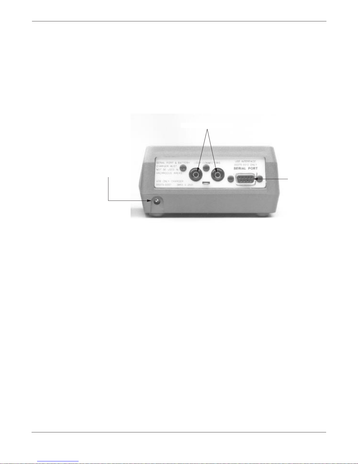
Rosemount Model 8732C Integral Mount Magnetic Flowmeter System
CONNECTIONS
AND HARDWARE
FIGURE A-2. Rear Connection Panel
with Optional NiCad Recharger Jack.
Optional NiCad
Recharger Jack
The HART Communicator exchanges information with the transmitter
from the control room, the instrument site, or any wiring termination
point in the loop. The HART Communicator should be connected in
parallel with the transmitter. Use the loop connection ports on the
rear panel of the HART Communicator (see Figure A-2). The
connections are non-polarized.
Do not make connections to the serial port or NiCad recharger jack in
an explosive atmosphere. Before connecting the HART Communicator
in an explosive atmosphere, make sure the instruments in the loop are
installed in accordance with intrinsically safe or nonincendive field
wiring practices.
Loop Connection Ports
Serial Port
275-008AB
A-4
 Loading...