

Page 1

Quick Installation Guide
Star t
Step 1: Pre-Installation
Step 2: Handling
Step 3: Mounting
Step 4: Installation (Flanged Flowtubes)
Step 4: Installation (Wafer Flowtubes)
Step 4: Installation (Sanitary Flowtubes)
Step 5: Grounding
Step 6: Wiring
Step 7: Basic Configuration
Step 8: Process Leak Protection (Optional)
Step 9: Power up the Transmitter
Step 10: Check Process Connections
Step 11: Confirm Configuration
End
00825-0100-4729, Rev BB
August 2015
Rosemount 8712H
Rosemount Magnetic Flowmeter
Systems (Transmitter and Flowtube)
www.rosemount.com
Page 2

Quick Installation Guide
IMPORTANT NOTICE
WARNING
00825-0100-4729, Rev BB
August 2015
© 2015 Rosemount Inc. All rights reserved. All marks property of owner.
Rosemount 8712H
This installation guide provides basic guidelines for the
Rosemount
configuration, diagnostics, maintenance, service and
troubleshooting installations. Refer to the 8712H reference manual
(document number 00809-0100-4729) for more instruction. The
manual and this QIG are also available electronically on
www.rosemount.com.
Failure to follow these installation guidelines could result in
death or serious injury:
Installation and servicing instructions are for use by qualified
personnel only. Do not perform any servicing other than that
contained in the operating instructions, unless qualified. Verify that
the operating environment of the flowtube and transmitter is
consistent with the appropriate FM or CSA approval.
Do not connect a Rosemount 8712H to a non-Rosemount flowtube
that is located in an explosive atmosphere.
®
8712H. It does not provide instructions for detailed
2
Page 3

Quick Installation Guide
WARNING
WARNING
00825-0100-4729, Rev BB
August 2015
Explosions could result in death or serious injury:
Installation of this transmitter in an explosive environment must be
in accordance with the appropriate local, national, and international
standards, codes, and practices. Please review the approvals
section of the 8712H reference manual for any restrictions
associated with a safe installation.
• Before connecting a HART-based communicator in an explosive
atmosphere, make sure the instruments in the loop are installed
in accordance with intrinsically safe or non-incendive field wiring
practices.
In an Explosion-Proof/Flame-Proof installation, do not remove the
flowtube cover when power is applied to the unit.
Electrical shock can result in death or serious injury
• Avoid contact with the leads and terminals. High voltage that
may be present on leads can cause electrical shock.
The flowtube liner is vulnerable to handling damage. Never place
anything through the flowtube for the purpose of lifting or gaining
leverage. Liner damage can render the flowtube useless.
To avoid possible damage to the flowtube liner ends, do not use
metallic or spiral-wound gaskets. If frequent removal is anticipated,
take precautions to protect the liner ends. Short spool pieces
attached to the flowtube ends are often used for protection.
Correct flange bolt tightening is crucial for proper flowtube operation
and life. All bolts must be tightened in the proper sequence to the
specified torque limits. Failure to observe these instructions could
result in severe damage to the flowtube lining and possible flowtube
replacement.
Rosemount 8712H
3
Page 4

Quick Installation Guide
STEP 1: PRE-INSTALLATION
4.31
(109)
LOI Cover
Standard
Cover
3.51
(89)
2.96
(75)
11.1 5
(283)
3.11
(79)
12.02
(305)
0.44
(11)
With LOI Cover
9.01
(229)
2.81
(71)
00825-0100-4729, Rev BB
August 2015
Rosemount 8712H
Before installing the Rosemount 8712H Magnetic Flowmeter
Transmitter, there are several pre-installation steps that should be
completed to make the installation process easier:
• Identify the options and configurations that apply to
your application
• Set the hardware switches if necessary
• Consider mechanical, electrical, and environmental requirements
Mechanical Considerations
The mounting site for the Rosemount 8712H transmitter should
provide enough room for secure mounting, easy access to conduit
ports, full opening of the transmitter covers, and easy readability of the
LOI screen (see Figure 1). The transmitter should be mounted in an
upright position.
If the 8712H is mounted separately from the flowtube, it
is not subject to limitations that might apply to the flowtube.
Figure 1. Rosemount 8712H Dimensional Drawing
4
Page 5

Quick Installation Guide
00825-0100-4729, Rev BB
August 2015
Rosemount 8712H
Environmental Considerations
To ensure maximum transmitter life, avoid excessive heat and
vibration. Typical problem areas:
• high-vibration lines with integrally mounted transmitters
• warm-climate installations in direct sunlight
• outdoor installations in cold climates.
Remote-mounted transmitters may be installed in the control room to
protect the electronics from the harsh environment and provides easy
access for configuration or service.
Both remotely and integrally mounted Rosemount 8712H transmitters
require external power and there must be access to a suitable power
source.
Installation Procedures
Rosemount 8712H installation includes both detailed mechanical and
electrical installation procedures.
Mount the Transmitter
At a remote site the transmitter may be mounted on a pipe up to two
inches in diameter or against a flat surface.
Pipe Mounting
To mount the transmitter on a pipe:
1. Attach the mounting plate to the pipe using the mounting hardware.
2. Attach the 8712H to the mounting plate using the mounting screws.
Surface Mounting
To surface mount the transmitter:
1. Attach the 8712H to the mounting location using the mounting
screws.
5
Page 6

Quick Installation Guide
00825-0100-4729, Rev BB
August 2015
Rosemount 8712H
Identify Options and Configurations
The standard application of the 8712H includes a 4–20 mA output and
control of the flowtube coils. Other applications may require one or
more of the following configurations or options:
• Multidrop Communications
• PZR (Positive Zero Return)
• Ultrasonic Control
• Auxiliary Output
• Pulse Output
Additional options may apply. Be sure to identify those options and
configurations that apply to your situation, and keep a list of them
nearby for consideration during the installation and configuration
procedures.
Hardware Jumpers/Switches
The 8712H electronics board is equipped with
three user-selectable hardware switches. These switches set the
Failure Alarm Mode, Internal/External Analog Power, and Transmitter
Security. The standard configuration for these switches when shipped
from the factory are as follows:
Failure Alarm Mode: HIGH
Internal/External Analog Power: INTERNAL
Transmitter Security: OFF
Changing Hardware Switch Settings
In most cases, it is not necessary to change the setting of the
hardware switches. If you need to change the switch settings,
complete the steps outlined in the manual.
Electrical Considerations
Before making any electrical connections to the 8712H, consider the
following standards and be sure to have the proper power supply,
conduit, and other accessories.
6
Page 7

Quick Installation Guide
STEP 2: HANDLING
3- through 4-Inch
Flowtubes
6-Inch and Larger
Flowtubes
8732-0281B02A, C02A
00825-0100-4729, Rev BB
August 2015
Handle all parts carefully to prevent damage. Whenever possible,
transport the system to the installation site in the original shipping
containers. Teflon
®
lined flowtubes are shipped with end covers that
protect it from both mechanical damage and normal unrestrained
distortion. Remove the end covers just before installation.
Figure 2. Rosemount 8705 Flowtube Support for Handling
Rosemount 8712H
7
Page 8

Quick Installation Guide
STEP 3: MOUNTING
5 Pipe Diameters
2 Pipe Diameters
Flow
8732-0281G02A
00825-0100-4729, Rev BB
August 2015
Rosemount 8712H
Upstream/Downstream Piping
To ensure specification accuracy over widely varying process
conditions, install the flowtube a minimum of five straight pipe
diameters upstream and two pipe diameters downstream from the
electrode plane (see Figure 3).
Figure 3. Upstream and Downstream Straight Pipe Diameters
Flow Direction
The flowtube should be mounted so that the FORWARD end of the
flow arrow, shown on the flowtube identification tag, points in the
direction of flow through the tube.
Flowtube Orientation
The flowtube should be installed in a position that ensures the
flowtube remains full during operation. Vertical installation allows
upward process fluid flow keeps the cross-sectional area full,
regardless of flow rate. Horizontal installation should be restricted to
low piping sections that are normally full. In these cases, orient the
electrode plane to within 45 degrees of horizontal.
8
Page 9

Quick Installation Guide
FLOW
FLOW
A
8735-0005A01A, 8732-0005A01C
8711-8711-E01A, 8711-8711-F01A
45° Electrode Plane
00825-0100-4729, Rev BB
August 2015
Figure 4. Flowtube Orientation
The electrodes in the Rosemount 8705 flowtube are properly
orientated when the two measurement electrodes are in the 3 and 9
o’clock positions, as shown on the right of Figure 4.
Figure 5. Rosemount 8711 Mounting Position
Rosemount 8712H
9
Page 10

Quick Installation Guide
STEP 4: INSTALLATION (FLANGED FLOWTUBE)
00825-0100-4729, Rev BB
August 2015
Rosemount 8712H
Gaskets
The flowtube requires a gasket at each of its connections to adjacent
devices or piping. The gasket material selected must be compatible with the
process fluid and operating conditions. Metallic o r spiral-wound gaskets
can damage the liner. Gaskets are required on each side of the
grounding ring. All other applications (including flowtubes with lining
protectors or a grounding electrode) require only one gasket on each
end connection.
Flange Bolts
Suggested torque values by flowtube line size and liner type are listed
in Table 1 for ASME B16.5 (ANSI) and Table 2 for DIN flanges.
Consult the factory if the flange rating of the flowtube is not listed.
Tighten flange bolts on the upstream side of the flowtube in the
incremental sequence shown in Figure 6 to 20% of the suggested
torque values. Repeat the process on the downstream side of the
flowtube. For flowtubes with more or less flange bolts, tighten the bolts
in a similar crosswise sequence. Repeat this entire tightening
sequence at 40%, 60%, 80%, and 100% of the suggested torque
values or until the leak between the process and flowtube flanges
stop.
If leakage has not stopped at the suggested torque values, the bolts
can be tightened in additional 10% increments until the joint stops
leaking, or until the measured torque value reaches the maximum
torque value of the bolts. Practical consideration for the integrity of the
liner often leads the user to distinct torque values to stop leakage due
to the unique combinations of flanges, bolts, gaskets, and flowtube
liner material.
Check for leaks at the flanges after tightening the bolts. Failure to use the
correct tightening methods can result in severe damage. Flowtubes require
a second tightening 24 hours after the initial installation. Over time,
flowtube liner materials may deform under pressure.
10
Page 11

Quick Installation Guide
1
5
3
7
8
4
6
2
8742f_01a.eps
8-bolt
00825-0100-4729, Rev BB
August 2015
Figure 6. Flange Bolt Torquing Sequence
Table 1. Suggested Flange Bolt Torque Values for
Rosemount 8705 and 8707 High-Signal Flowtubes
Teflon/Tefzel/PFA liners
Size
Code
005
010 1 inch (25 mm) 8 12 - -
015 1
Line Size
1
/2-inch (15 mm) 8 8 - -
1
/2 inch (40 mm) 13 25 7 18
020 2 inch (50 mm) 19 17 14 11
030 3 inch (80 mm) 34 35 23 23
040 4 inch (100 mm) 26 50 17 32
060 6 inch (150mm) 45 50 30 37
080 8 inch (200 mm) 60 82 42 55
100 10 inch (250 mm) 55 80 40 70
120 12 inch (300 mm) 65 125 55 105
140 14 inch (350 mm) 85 110 70 95
160 16 inch (400 mm) 85 160 65 140
180 18 inch (450 mm) 120 170 95 150
200 20 inch (500 mm) 110 175 90 150
240 24 inch (600 mm) 165 280 140 250
300 30 inch (750 mm) 195 415 165 375
360 36 inch (900 mm) 280 575 245 525
Class 150
(pound-feet)
(pound-feet)
Rosemount 8712H
Polyurethane/Neoprene/
Class 300
Class 150
(pound-feet)
Linatex liners
Class 300
(pound-feet)
11
Page 12

Quick Installation Guide
00825-0100-4729, Rev BB
August 2015
Rosemount 8712H
Table 2. Flange Bolt Torque and Bolt Load Specifications for 8705
Teflon/Tefzel liner
(Newton-
meter)
10 4400 10 4400
20 10100 20 10100
50 16100 50 16100
60 20100 60 20100
50 16800 50 16800
50 17800 70 19600
90 24700 130 28700
(Newton)
(Newton-
meter)
(Newton)
(Newton-
meter)
Size
Code
Line Size
005 0.5-inch
(15 mm)
010 1 inch
(25 mm)
015 1.5 inch
(40 mm)
020 2 inch
(50 mm)
030 3 inch
(80 mm)
040 4 inch
(100 mm)
060 6 inch
(150mm)
080 8 inch
(200 mm)
100 10 inch
(250 mm)
120 12 inch
(300 mm)
140 14 inch
(350 mm)
160 16 inch
(400 mm)
180 18 inch
(450 mm)
200 20 inch
(500 mm)
240 24 inch
(600 mm)
PN10 PN 16 PN 25 PN 40
(Newton-
meter)
(Newton)
130 35200 90 19700 130 29200 170 34400
100 28000 130 28300 190 38000 250 44800
120 32000 170 38400 190 38600 270 47700
160 43800 220 49500 320 57200 410 68100
220 50600 280 56200 410 68100 610 92900
190 43200 340 68400 330 55100 420 64000
230 51100 380 68900 440 73300 520 73900
290 58600 570 93600 590 90100 850 112000
(Newton)
12
Page 13

Quick Installation Guide
00825-0100-4729, Rev BB
August 2015
Rosemount 8712H
Size
Code
Line Size
010 1 inch
(25 mm)
015 1.5 inch
(40 mm)
020 2 inch
(50 mm)
030 3 inch
(80 mm)
040 4 inch
(100 mm)
060 6 inch
(150mm)
080 8 inch
(200 mm)
100 10 inch
(250 mm)
120 12 inch
(300 mm)
140 14 inch
(350 mm)
160 16 inch
(400 mm)
180 18 inch
(450 mm)
200 20 inch
(500 mm)
240 24 inch
(600 mm)
PN 10 PN 16 PN 25 PN 40
(Newton-
meter)
90 23400 60 13100 90 19400 110 22800
70 18600 80 18800 130 25400 170 29900
80 21300 110 25500 130 25800 180 31900
110 29100 150 33000 210 38200 280 45400
150 33700 190 37400 280 45400 410 62000
130 28700 230 45600 220 36800 280 42700
150 34100 260 45900 300 48800 350 49400
200 39200 380 62400 390 60100 560 74400
Polyurethane, Linatex, and Neoprene Liners
(Newton-
meter)
(Newton)
(Newton)
20 7040 20 7040
30 10700 30 10700
40 13400 40 13400
30 111 00 30 11100
40 11700 50 13200
60 16400 90 19200
(Newton-
meter)
(Newton)
(Newton-
meter)
(Newton)
13
Page 14
Quick Installation Guide
STEP 5: GROUNDING
8705-0040C
Earth
Ground
00825-0100-4729, Rev BB
August 2015
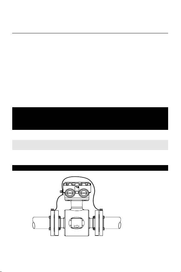
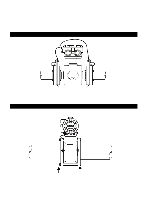
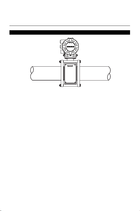
Use Table 3 to determine which grounding option to follow for proper
installation. The flowtube case should always be earth grounded in
accordance with national and local electrical codes. Failure to do so
may impair the protection provided by the equipment. The Internal
Ground Connection (Protective Ground Connection) located in side
the junction box is the Internal Ground Connection screw. This screw
is identified by the ground symbol.
Table 3. Grounding Installation
Type of Pipe
Conductive Unlined
Pipe
Conductive Lined
Pipe
Non-Conductive Pipe Insufficient
Figure 7. No Grounding Options or Grounding Electrode in Lined Pipe
Grounding Options
No
Grounding
Options
See Figure 7 Not Required Not Required See Figure 8
Insufficient
Grounding
Grounding
Grounding
Rings
See Figure 8 See Figure 7 See Figure 8
See Figure 9 See Figure 10 See Figure 9
Rosemount 8712H
Grounding
Electrodes
Lining
Protectors
14
Page 15
Quick Installation Guide
8705-038C
Earth
Ground
Grounding Rings or Lining
Protectors
Earth
Ground
8711-0360a01b
Grounding Rings
00825-0100-4729, Rev BB
August 2015
Figure 8. Grounding with Grounding Rings or Lining Protectors
Figure 9. Grounding with Grounding Rings or Lining Protectors
Rosemount 8712H
15
Page 16
Quick Installation Guide
STEP 6: WIRING
8711-0360a01a
Earth
Ground
00825-0100-4729, Rev BB
August 2015
Figure 10. Grounding with Grounding Electrodes
Rosemount 8712H
Conduit Ports and Connections
Both the flowtube and transmitter junction boxes have ports for ¾-inch
NPT conduit connections. These connections should be made in
accordance with local or plant electrical codes. Unused ports should
be sealed with metal plugs. Proper electrical installation is necessary
to prevent errors due to electrical noise and interference. Separate
conduits are not necessary for the two cables, but a dedicated conduit
line between each transmitter and flowtube is required. Shielded cable
must be used for best results in electrically noisy environments.
Conduit Cables
Run the appropriate size cable through the conduit connections in your
magnetic flowmeter system. Run the power cable from the power
source to the transmitter. Run the coil drive and electrode cables
between the flowmeter and transmitter. Prepare the ends of the coil
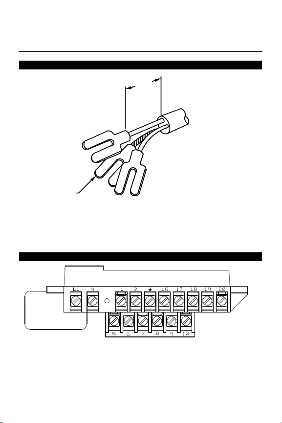
drive and electrode cables as shown in Figure 11. Limit the unshielded
wire length to 1-inch on both the electrode and coil drive cables.
Excessive lead length or failure to connect cable shields can create
electrical noise resulting in unstable meter readings.
16
Page 17
Quick Installation Guide
8705_0041a.eps
NOTE
Dimensions are in
inches (millimeters).
1.00
(26)
Cable Shield
8712/8712e01c.eps
00825-0100-4729, Rev BB
August 2015
Figure 11. Cable Preparation Detail
Rosemount 8712H
Step 6.1 Transmitter Coil Input
This wiring section covers supplying power to the flowtube coils
through the transmitter. The transmitter coil input power sends a
pulsed DC frequency to the flowtube.
Figure 12. Transmitter Power Connections
17
Page 18
Quick Installation Guide
Power Supply (Volts)
15
50
20
30
40
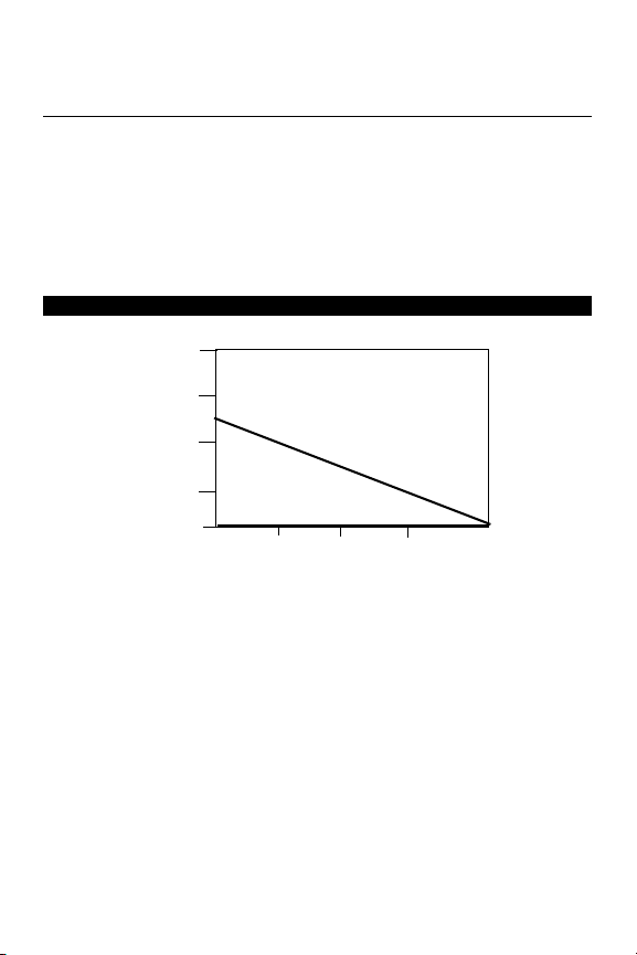
I = 10/V
I = Supply current requirement (Amps)
V = Power supply voltage (Volts)
Supply Current (Amps)
1.0
0.75
0.5
0.25
0
00825-0100-4729, Rev BB
August 2015
Wire the transmitter according to local electrical requirements. Ground
the transmitter cage via the threaded conduit connection (see
Figure 11). For ac power applications, connect ac Neutral to terminal N
and connect ac Line to terminal L1. For dc power applications,
properly connect the positive and negative terminals. Units powered
by 10-30 V dc power supply may draw up to 1 amp of current. In
addition, follow the supply wire and disconnect requirements below:
Figure 13. Power Supply Current
Supply Wire Requirements
Use 12 to 18 AWG wire rated for the proper temperature application.
For connections in ambient temperatures above 140 °F (60 °C), use a
wire rated for at least 176 °F (80 °C). For ambients greater than 176 °F
(80 °C), use a wire rated for at least 230 °F (110 °C).
Disconnects
Connect the device through an external disconnect or circuit breaker.
Clearly label the disconnect or circuit breaker and locate it near
the transmitter and per local electrical control.
18
Rosemount 8712H
Page 19

Quick Installation Guide
MaximumResis cetan
SupplyVoltage 10Vdc–
SurgeCurrent
----------------------------------------------------------- ---------=
00825-0100-4729, Rev BB
August 2015
Rosemount 8712H
Installation Category
The installation category for the Rosemount 8712H is (Overvoltage)
Category II.
Overcurrent Protection
The Rosemount 8712H Flowmeter Transmitter requires overcurrent
protection of the supply lines. Maximum ratings of overcurrent devices
are as follows:
Power
System
110 V ac 250 V; 1 Amp, Quick Acting Bussman AGCI or Equivalent
220 V ac 250 V; 0.5 Amp, Quick Acting Bussman AGCI or Equivalent
Requirements for 115 V ac or 230 V ac Power Supply
Wire the transmitter according to local electrical requirements for
115 V ac or 230 V ac. In addition, follow the supply wire and
disconnect requirements below:
Requirements for 10–30 V dc Power Supply
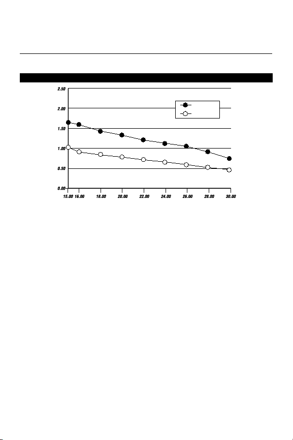
Units powered with 10–30 V dc may draw up to 2 amps of current. As
a result, the input power wire must meet certain gauge requirements.
For combinations not shown, you can calculate the maximum distance
given the surge current, the voltage of the source, and the minimum
start-up voltage of the transmitter, 10 V dc, using the following
equation:
Fuse Rating Manufacturer
19
Page 20

Quick Installation Guide
00825-0100-4729, Rev BB
August 2015
Table 4. Length of Annealed Copper (Cu) Wires
Table 5. Length of Hand-drawn Copper (Cu) Wires
Typ es o f
Power Supply Wires
Wire
Gauge
Power Supply Wires
Wire
Gauge
18 6.640 (21.78) 1,880
16 4.176 (13.70) 2,990
14 2.626 (8.61) 4,760
12 1.652 (5.42) 7,565
10 1.039 (3.41) 12,030
Annealed Cu
milliohms/ft
(milliohms/m)
20 10.15 (33.29) 1,230
18 6.385 (20.94) 1,955
16 4.016 (13.17) 3,110
14 2.525 (8.28) 4,950
12 1.588 (5.21) 7,870
10 0.999 (3.28) 12,510
Types of
Hand-drawn Cu
milliohms/ft
(milliohms/m)
Supply
(1,451)
(2,306)
(3,667)
Maximum Length of the Wire for Each
Corresponding Power Supply Source
30 V
Supply
ft (m)
(375)
(596)
(948)
(1,509)
(2,399)
(3,813)
Maximum Length of the Wire for Each
Corresponding Power Supply Source
30 V
ft (m)
(573)
(911)
955 (291) 565 (172) 180 (55)
1,520 (463) 895 (273) 285 (87)
2,415 (736) 1,425 (434) 455 (139)
6,110 (1862) 3,605 (1,099) 1,155 (352)
Rosemount 8712H
24 V
Supply
ft (m)
625 (191) 365 (111) 115 (35)
990 (302) 585 (178) 185 (56)
1,580
(482)
2,515
(767)
3,995
(1,218)
6,355
(1,937)
24 V
Supply
ft (m)
3,840
(1,170)
20 V
ft (m)
3,750
ft (m)
14 V Supply
ft (m)
1,200 (366)
14 V
Supply
ft (m)
Supply
930 (283) 295 (90)
1,485 (453) 475 (145)
2,360 (719) 755 (230)
(1,143)
20 V Supply
2,270 (692) 725 (221)
20
Page 21
Quick Installation Guide
8712-0388A
Surge
Nominal
Supply Current (Amperes)
Input Voltage (Volts)
00825-0100-4729, Rev BB
August 2015
Rosemount 8712H
Options, Considerations, and Procedures
Figure 14. Supply Current versus Input Voltage
Step 6.2 Transmitter Communication Input
Connect 4–20 mA Loop External Power Source
The 4–20 mA output loop signal may be powered internally or
externally. The default position of the internal/external analog power
jumper is in the internal position. The user-selectable power supply
jumper is located on the electronics board.
Internal
The 4–20 mA analog power loop may be powered from the transmitter
itself. Resistance in the loop must be 1,000 ohms or less. If a HART
Communicator or control system will be used, it must be connected
across a minimum of 250 ohms resistance in the loop.
External
HART multidrop installations require a 10–30 V dc external analog
power source. If a HART Communicator or control system is to be
used, it must be connected across a minimum of 250 ohms resistance
in the loop.
To connect external power to the 4–20 mA loop, connect -dc to
Terminal 8 and +dc to Terminal 7. (See Figure 12)
21
Page 22
Quick Installation Guide
Coil Drive
and
Electrode
Cables
Power
Outputs
Power
Outputs
8705/0000a01a, 0000a01b.eps
Coil
Drive and
Electrode
Cables
Power
Outputs
Power
Outputs
00825-0100-4729, Rev BB
August 2015
Rosemount 8712H
NOTE
To connect any of the other output options (pulse output for totalizing,
auxiliary output for switch closure, or positive zero return), consult the
the comprehensive product manual.
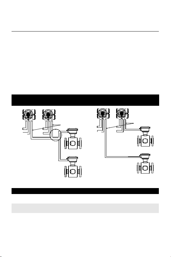
Step 6.3 Transmitter to Flowtube Wiring
A single dedicated conduit run for the coil drive and electrode cables is
needed between a flowtube and a remote transmitter. Bundled cables
in a single conduit are likely to create interference and noise problems
in your system. Use one set of cables per conduit run.
Figure 15. Conduit Preparation
Wrong Right
Table 6. Cable Requirements
Description Length Part Number
Signal Cable (20 AWG) Belden
8762, Alpha 2411 equivalent
Coil Drive Cable (14 AWG) Belden
8720, Alpha 2442 equivalent
Combination Signal and Coil Drive
Cable (18 AWG)
(1) Combination signal and coil drive cable is not recommended for
high-signal magmeter system. For remote mount installations, combination
signal and coil drive cable should be limited to less than 100 ft. (30 m).
(1)
ft
m
ft
m
ft
m
22
08712-0061-0001
08712-0061-0003
08712-0060-0001
08712-0060-0003
08712-0752-0001
08712-0752-0003
Page 23
Quick Installation Guide
8712-03A
00825-0100-4729, Rev BB
August 2015
Rosemount 8712H
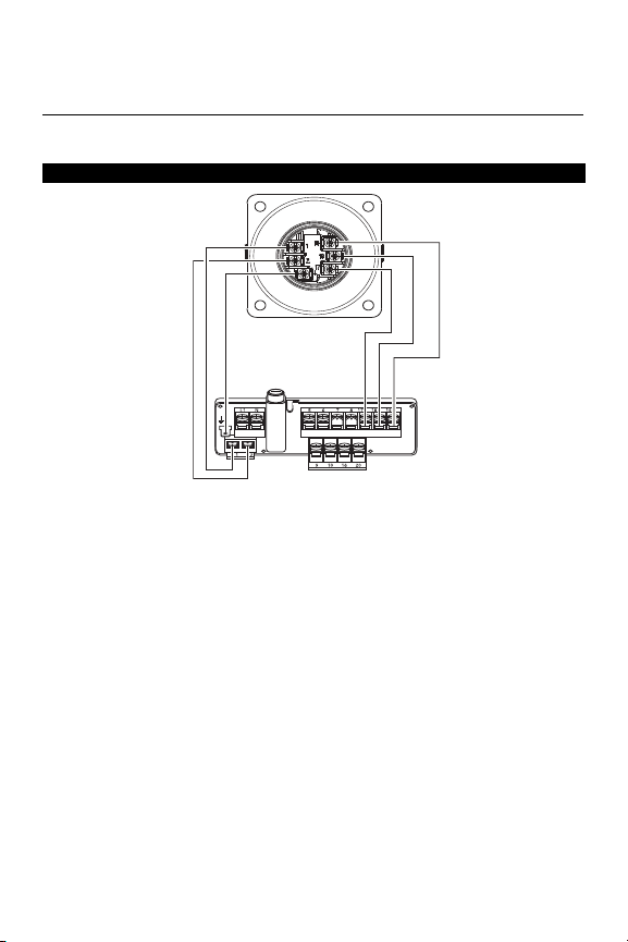
High-Signal Flowtube to High-Signal Transmitter
Figure 16. Wiring Diagram
Step 7: Basic Configuration
Once the magnetic flowmeter is installed and power has been
supplied, transmitter must be configured through the basic setup.
These parameters can be configured through either a local operator
interface, a HART Communicator or AMS. A table of all the
parameters are on page 25. Descriptions of the more advanced
functions are included in the comprehensive product manual.
Basic Setup
Tag
Tag is the quickest and shortest way of identifying and distinguishing
between transmitters. Transmitters can be tagged according to the
requirements of your application. The tag may be up to eight
characters long.
23
Page 24

Quick Installation Guide
00825-0100-4729, Rev BB
August 2015
Rosemount 8712H
Flow Rate Units
The flow rate units variable specifies the format in which the flow rate
will be displayed. Units should be selected to meet your particular
metering needs.
URV (Upper Range Value)
The upper range value (URV), or analog output range, is preset to 30
ft/s at the factory. The units that appear will be the same as those
selected under the units parameter.
LRV (Lower Range Value)
Reset the lower range value (LRV), or analog output zero, to change
the size of the range (or span) between the URV and LRV. Under
normal circumstances, the LRV should be set to a value near the
minimum expected flow rate to maximize resolution. The LRV must be
between –30 ft/s to 30 ft/s.
Line Size
The line size (tube size) must be set to match the actual flowtube
connected to the transmitter. The size must be specified in inches
according to the available sizes listed below.
Calibration Number
The tube calibration number is a 16-digit number used to identify
flowtubes calibrated at the Rosemount factory.
24
Page 25

Quick Installation Guide
00825-0100-4729, Rev BB
August 2015
Function HART Fast Keys LOI Key
PROCESS VARIABLES 1, 1
DIAGNOSTICS AND SERVICE
Analog Output Test 1, 1, 3 Aux. function
Pulse Output Test 1, 2, 3 Aux. Function
Self Test 1, 2, 1, 2 Aux. Function
D/A Trim and (4-20 mA
Output Trim
Scaled D/A Trim 1, 2, 4, 2
Electronics Trim 1, 2, 4, 3 Aux. Function
Auto Zero Trim 1, 2, 4, 4 Aux. Function
Universal Auto Trim
(8712U Only)
BASIC SETUP
Ta g 1, 3, 1 XMTR Info
Flow Rate Units 1, 3, 2, 1 Units
URV (Upper Range Value) 1, 3, 3 Analog Output Range
LRV (Lower Range Value) 1, 3, 4 Aux. Function
Line Size 1, 3, 5 Tube Size
Calibration Number 1, 3, 6 Tube Cal No.
Damping 1, 3, 7 Damping
DETAILED SETUP
Pulse Output Scaling 1, 4, 3, 2, 1 Aux. Function
Pulse Width 1, 4, 3, 2, 2 Aux. Function
Special Units 1, 3, 2, 2 Aux. Function
User-Defined Volume Unit 1, 3, 2, 2, 1 Aux. Function
Base Volume Unit 1, 3, 2, 2, 2 Aux. Function
Conversion Number 1, 3, 2, 2, 3 Aux. Function
Base Tim Unit 1, 3, 2, 2, 4 Aux. Function
User-Defined Flow Unit 1, 3, 2, 2, 5 Aux. Function
Auxiliary Output 1, 4, 3, 3 Aux. Function
Totalizer 1, 1, 4 Totalizer
Measure Gross Total 1, 1, 4, 1 Totalizer
Start Totalizer 1, 1, 4, 4 Totalizer
Stop Totalizer 1, 1, 4, 5 Totalizer
Reset Totalizer 1, 1, 4, 6 Totalizer
Low Flow Cutoff 1, 4, 4, 1 Aux. Function
Coil Dive Frequency 1, 4, 1, 3 Aux. Function
Control Status 1, 4, 4, 4 Aux. Function
1, 2, 4, 1 Aux. Function
1, 2, 4, 5 Aux. Function
Rosemount 8712H
25
Page 26

Quick Installation Guide
00825-0100-4729, Rev BB
August 2015
Function HART Fast Keys LOI Key
Signal Processing Control 1, 4, 4 Aux. Function
Number of Samples 1, 4, 4, 5 Aux. Function
Maximum Percent Limit 1, 4, 4, 6 Aux. Function
Time Limit 1, 4, 4, 7 Aux. Function
REVIEW VARIABLES
Review 1, 5
MISCELLANEOUS FUNCTIONS
Coil Current
(8712U Only)
Transmitter Gain
(8712U Only)
Flowtube Gain
(8712U Only)
Message 1, 4, 5, 4 XMTR Info
Date 1, 4, 5, 5 XMTR Info
Flowtube Tag 1, 4, 5, 8 XMTR Info
Flowtube Serial Number 1, 4, 5, 7 XMTR Info
Liner Material XMTR Info
Electrode Type XMTR Info
Electrode Material XMTR Info
1, 4, 1, 7 Aux. Function
1, 4, 1, 8 Aux. Function
1, 4, 1, 9 Aux. Function
Rosemount 8712H
26
Page 27

Quick Installation Guide
00825-0100-4729, Rev BB
August 2015
Rosemount 8712H
Product Certificates
Approved Manufacturing Locations
Rosemount Inc. — Eden Prairie, Minnesota, USA
Fisher-Rosemount Technologias de Flujo, S.A. de C.V. —
Chihuahua, Chihuahua, Mexico
Other important guidelines
Only use new, original parts.
To prevent the process medium escaping, do not unscrew or remove
process flange bolts, adapter bolts or bleed screws during operation.
Maintenance shall only be done by qualified personnel.
Hazardous Location Certifications
North American Certifications
Factory Mutual (FM)
N0 Division 2 Approval (All transmitters)
Class I, Division 2, Groups A, B, C, D
Temp Codes – T4 (at 40°C),
Dust-ignition proof Class II/III, Division 1, Groups E, F, G
Temp Codes – T4 (at 40°C),
Enclosure Type 4X
Canadian Standards Association (CSA)
N0 Suitable for Class I, Division 2, Groups A, B, C, D
Temp Codes – T4 (at 60°C)
Dust-ignition proof Class II/III, Division 1, Groups E, F, G
Enclosure Type 4X
27
Page 28

Quick Installation Guide
00825-0100-4729, Rev BB
August 2015
Factory Mutual (FM)
N0 Division 2 Approval for
Non-Flammable Fluids (8707)
Class I, Division 2, Groups A, B, C, D
Temp Code – T5 (8705/8711 at 60°C)
Temp Code – T3C (8707 at 60°C)
Dust-Ignition proof Class II/III, Division 1, Groups E, F, G
Temp Code – T6 (8705/8711 at 60°C)
Temp Code – T5 (8707 at 60°C)
Enclosure Type 4X
Canadian Standards Association (CSA)
N0 Suitable for Class I, Division 2, Groups A, B, C, D
Temp Code – T5 (8705/8711 at 60°C)
Temp Code – T3C (8707 at 60°C)
Dust-Ignition proof Class II/III, Division 1, Groups E, F, G
Enclosure Type 4X
Rosemount 8712H
28
Page 29

Global Headquarters
Emerson Process Management
6021 Innovation Blvd
Shakopee, MN 55379, USA
+1 800 522 6277 or +1 303 527 5200
+1 303 530 8459
[email protected]
North America Regional Office
Emerson Process Management
7070 Winchester Circle
Boulder, CO 80301 USA
+1 800 522 6277 or +1 303 527 5200
+1 303 530 8459
[email protected]
Latin America Regional Office
Emerson Process Management
Multipark Office Center
Turrubares Building, 3rd & 4th floor
Guachipelin de Escazu, Costa Rica
+1 506 2505-6962
+1 954 846 5121
[email protected]
Europe Regional Office
Emerson Process Management Flow B.V.
Neonstraat 1
6718 WX Ede
The Netherlands
+31 (0) 318 495555
+31 (0) 318 495556
[email protected]
Asia Pacific Regional Office
Emerson Process Management Asia Pacific Pte
Ltd
1 Pandan Crescent
Singapore 128461
+65 6777 8211
+65 6777 0947
[email protected]
00825-0100-4729
Quick Start Guide
00825-0100-4729, Rev. BB
August 2015
Middle East and Africa Regional
Office
Emerson Process Management
Emerson FZE P.O. Box 17033,
Jebel Ali Free Zone - South 2
Dubai, United Arab Emirates
+971 4 8118100
+971 4 8865465
[email protected]
Standard Terms and Conditions of Sale can be
found at: www.rosemount.com\terms_of_sale.
The Emerson logo is a trademark and service
mark of Emerson Electric Co.
Rosemoun t and Rosemou nt logoty pe are
registered trademarks of Rosemount Inc.
All other marks are the property of their
respective owners.
© 2015 Rosemount Inc. All rights reserved.
 Loading...