

Page 1
Reference Manual
00809-0100-4664, Rev BA
January 2010
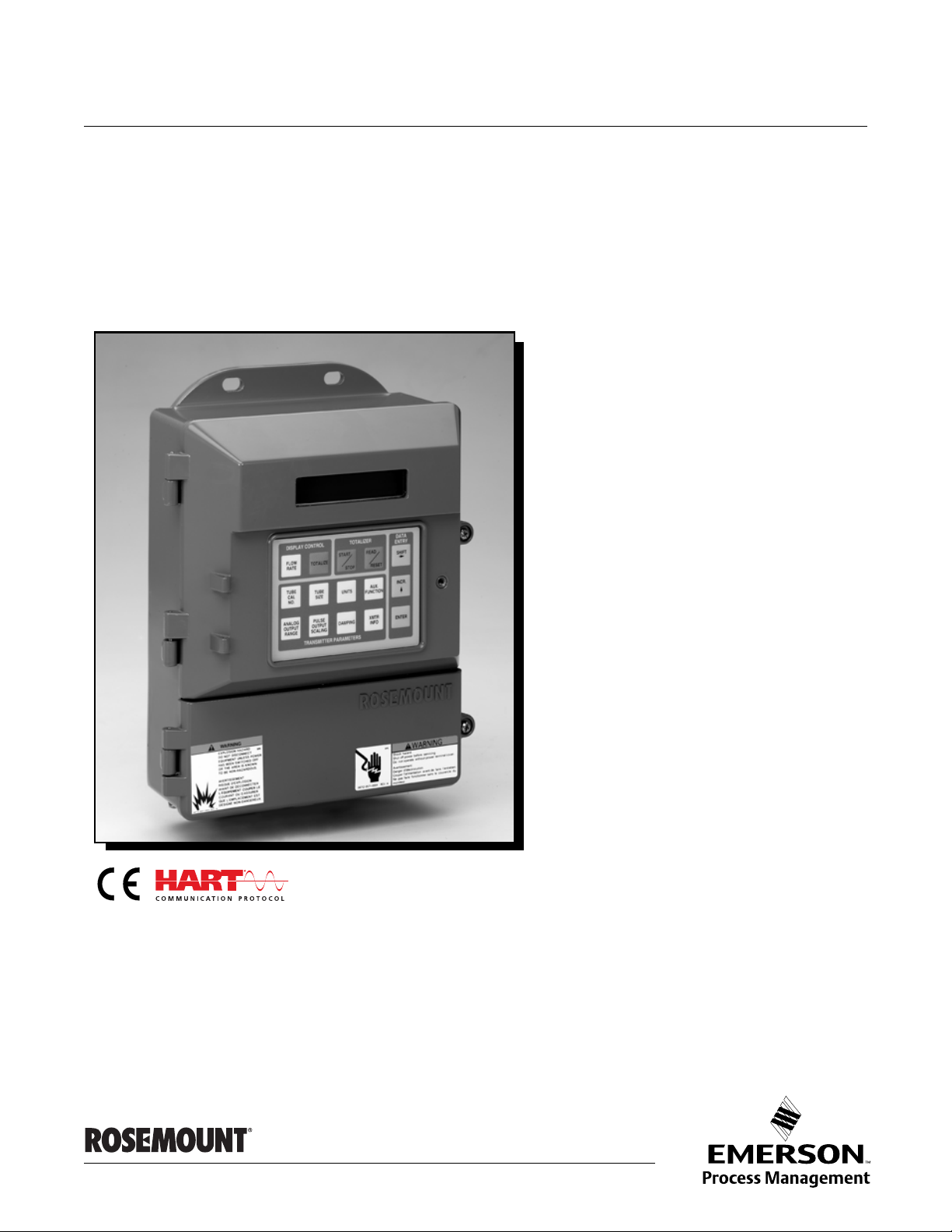
Rosemount 8712
Remote Mount Magnetic Flowmeter System
www.rosemount.com
Page 2

Page 3

Reference Manual
NOTICE
00809-0100-4664, Rev BA
January 2010
Rosemount 8712
Remote Mount Magnetic Flowmeter System
Read this manual before working with the product. For personal and system safety, and for
optimum product performance, make sure you thoroughly understand the contents before
installing, using, or maintaining this product.
Rosemount Inc. has two toll-free assistance numbers:
Customer Central
Technical support, quoting, and order-related questions.
United States - 1-800-999-9307 (7:00 am to 7:00 pm CST)
Asia Pacific- 65 777 8211
Europe/ Middle East/ Africa - 49 (8153) 9390
North American Response Center
Equipment service needs.
1-800-654-7768 (24 hours—includes Canada)
Outside of these areas, contact your local Emerson Process Management representative.
The products described in this document are NOT designed for nuclear-qualified
applications. Using non-nuclear qualified products in applications that require
nuclear-qualified hardware or products may cause inaccurate readings.
For information on Rosemount nuclear-qualified products, contact your local Emerson
Process Management Sales Representative.
www.rosemount.com
Page 4

Page 5

Reference Manual
00809-0100-4664, Rev BA
January 2010
Rosemount 8732
Table of Contents
SECTION 1
Introduction
SECTION 2
Installation
System Description. . . . . . . . . . . . . . . . . . . . . . . . . . . . . . . . . . . . . . . 1-1
Safety Messages . . . . . . . . . . . . . . . . . . . . . . . . . . . . . . . . . . . . . . . . 1-2
Service Support . . . . . . . . . . . . . . . . . . . . . . . . . . . . . . . . . . . . . . . . . 1-2
Safety Messages . . . . . . . . . . . . . . . . . . . . . . . . . . . . . . . . . . . . . . . . 2-1
Transmitter Symbols. . . . . . . . . . . . . . . . . . . . . . . . . . . . . . . . . . . . . . 2-2
Pre-Installation . . . . . . . . . . . . . . . . . . . . . . . . . . . . . . . . . . . . . . . . . . 2-2
Mechanical Considerations . . . . . . . . . . . . . . . . . . . . . . . . . . . . . . 2-2
Environmental Considerations. . . . . . . . . . . . . . . . . . . . . . . . . . . . 2-4
Installation Procedures. . . . . . . . . . . . . . . . . . . . . . . . . . . . . . . . . . . . 2-4
Mount the Transmitter . . . . . . . . . . . . . . . . . . . . . . . . . . . . . . . . . . 2-4
Identify Options and Configurations . . . . . . . . . . . . . . . . . . . . . . . 2-4
Hardware Switches . . . . . . . . . . . . . . . . . . . . . . . . . . . . . . . . . . . . 2-4
Conduit Ports and Connections. . . . . . . . . . . . . . . . . . . . . . . . . . . 2-6
Conduit Cables . . . . . . . . . . . . . . . . . . . . . . . . . . . . . . . . . . . . . . . 2-6
Electrical Considerations. . . . . . . . . . . . . . . . . . . . . . . . . . . . . . . . 2-7
Installation Category . . . . . . . . . . . . . . . . . . . . . . . . . . . . . . . . . . . 2-9
Overcurrent Protection . . . . . . . . . . . . . . . . . . . . . . . . . . . . . . . . . 2-9
Options, Considerations, and Procedures . . . . . . . . . . . . . . . . . . . . . 2-9
Connect Transmitter Power. . . . . . . . . . . . . . . . . . . . . . . . . . . . . . 2-9
Connect 4–20 mA Loop External Power Source. . . . . . . . . . . . . . 2-9
Connect Pulse Output Power Source . . . . . . . . . . . . . . . . . . . . . 2-10
Connect Auxiliary Channel 1. . . . . . . . . . . . . . . . . . . . . . . . . . . . 2-11
Connect Auxiliary Channel 2. . . . . . . . . . . . . . . . . . . . . . . . . . . . 2-12
sensor Connections . . . . . . . . . . . . . . . . . . . . . . . . . . . . . . . . . . . . . 2-13
Rosemount Sensors . . . . . . . . . . . . . . . . . . . . . . . . . . . . . . . . . . 2-13
Transmitter to Sensor Wiring. . . . . . . . . . . . . . . . . . . . . . . . . . . . 2-13
Conduit Cables . . . . . . . . . . . . . . . . . . . . . . . . . . . . . . . . . . . . . . 2-14
Sensor to Remote Mount Transmitter Connections . . . . . . . . . . 2-15
SECTION 3
Configuration
Introduction. . . . . . . . . . . . . . . . . . . . . . . . . . . . . . . . . . . . . . . . . . . . . 3-1
Installation Check and Guide . . . . . . . . . . . . . . . . . . . . . . . . . . . . . . . 3-1
Local Operator Interface. . . . . . . . . . . . . . . . . . . . . . . . . . . . . . . . . . . 3-2
Basic Features . . . . . . . . . . . . . . . . . . . . . . . . . . . . . . . . . . . . . . . . . . 3-3
Data Entry . . . . . . . . . . . . . . . . . . . . . . . . . . . . . . . . . . . . . . . . . . . 3-3
Selecting Options . . . . . . . . . . . . . . . . . . . . . . . . . . . . . . . . . . . . . 3-4
LOI Examples. . . . . . . . . . . . . . . . . . . . . . . . . . . . . . . . . . . . . . . . . . . 3-4
Table Value Example . . . . . . . . . . . . . . . . . . . . . . . . . . . . . . . . . . 3-4
Select Value Example . . . . . . . . . . . . . . . . . . . . . . . . . . . . . . . . . . 3-4
Diagnostic Messages . . . . . . . . . . . . . . . . . . . . . . . . . . . . . . . . . . . . . 3-6
Review. . . . . . . . . . . . . . . . . . . . . . . . . . . . . . . . . . . . . . . . . . . . . . 3-6
Process Variables. . . . . . . . . . . . . . . . . . . . . . . . . . . . . . . . . . . . . . . . 3-6
PV - Primary Variable . . . . . . . . . . . . . . . . . . . . . . . . . . . . . . . . . . 3-7
PV -% Range. . . . . . . . . . . . . . . . . . . . . . . . . . . . . . . . . . . . . . . . . 3-7
PV - Analog Output . . . . . . . . . . . . . . . . . . . . . . . . . . . . . . . . . . . . 3-7
Totalizer Setup . . . . . . . . . . . . . . . . . . . . . . . . . . . . . . . . . . . . . . . 3-7
Pulse Output . . . . . . . . . . . . . . . . . . . . . . . . . . . . . . . . . . . . . . . . . 3-8
TOC-1
Page 6

Reference Manual
00809-0100-4664, Rev BA
January 2010
Rosemount 8732
Basic Setup. . . . . . . . . . . . . . . . . . . . . . . . . . . . . . . . . . . . . . . . . . . . . 3-8
Tag . . . . . . . . . . . . . . . . . . . . . . . . . . . . . . . . . . . . . . . . . . . . . . . . 3-8
Flow Units . . . . . . . . . . . . . . . . . . . . . . . . . . . . . . . . . . . . . . . . . . . 3-8
Line Size . . . . . . . . . . . . . . . . . . . . . . . . . . . . . . . . . . . . . . . . . . . 3-10
PV URV (Upper Range Value) . . . . . . . . . . . . . . . . . . . . . . . . . . 3-11
PV LRV (Lower Range Value). . . . . . . . . . . . . . . . . . . . . . . . . . . 3-11
Calibration Number . . . . . . . . . . . . . . . . . . . . . . . . . . . . . . . . . . . 3-12
PV Damping . . . . . . . . . . . . . . . . . . . . . . . . . . . . . . . . . . . . . . . . 3-12
SECTION 4
Operation
SECTION 5
Sensor Installation
Introduction. . . . . . . . . . . . . . . . . . . . . . . . . . . . . . . . . . . . . . . . . . . . . 4-1
Diagnostics. . . . . . . . . . . . . . . . . . . . . . . . . . . . . . . . . . . . . . . . . . . . . 4-1
Diagnostic Controls . . . . . . . . . . . . . . . . . . . . . . . . . . . . . . . . . . . . 4-1
Basic Diagnostics . . . . . . . . . . . . . . . . . . . . . . . . . . . . . . . . . . . . . 4-2
Advanced Diagnostics. . . . . . . . . . . . . . . . . . . . . . . . . . . . . . . . . . 4-7
Diagnostic Variable Values . . . . . . . . . . . . . . . . . . . . . . . . . . . . . 4-12
Trims . . . . . . . . . . . . . . . . . . . . . . . . . . . . . . . . . . . . . . . . . . . . . . 4-14
Status . . . . . . . . . . . . . . . . . . . . . . . . . . . . . . . . . . . . . . . . . . . . . 4-16
Advanced Configuration . . . . . . . . . . . . . . . . . . . . . . . . . . . . . . . . . . 4-16
Detailed Setup . . . . . . . . . . . . . . . . . . . . . . . . . . . . . . . . . . . . . . . . . 4-16
Additional Parameters. . . . . . . . . . . . . . . . . . . . . . . . . . . . . . . . . 4-16
Configure Outputs . . . . . . . . . . . . . . . . . . . . . . . . . . . . . . . . . . . . 4-17
LOI Configuration . . . . . . . . . . . . . . . . . . . . . . . . . . . . . . . . . . . . 4-31
Signal Processing . . . . . . . . . . . . . . . . . . . . . . . . . . . . . . . . . . . . 4-31
Universal Auto Trim. . . . . . . . . . . . . . . . . . . . . . . . . . . . . . . . . . . 4-34
Device Info. . . . . . . . . . . . . . . . . . . . . . . . . . . . . . . . . . . . . . . . . . 4-34
Safety Messages . . . . . . . . . . . . . . . . . . . . . . . . . . . . . . . . . . . . . . . . 5-1
Sensor Handling. . . . . . . . . . . . . . . . . . . . . . . . . . . . . . . . . . . . . . . . . 5-3
Sensor Mounting. . . . . . . . . . . . . . . . . . . . . . . . . . . . . . . . . . . . . . . . . 5-4
Upstream/Downstream Piping. . . . . . . . . . . . . . . . . . . . . . . . . . . . 5-4
Sensor Orientation. . . . . . . . . . . . . . . . . . . . . . . . . . . . . . . . . . . . . 5-4
Flow Direction . . . . . . . . . . . . . . . . . . . . . . . . . . . . . . . . . . . . . . . . 5-6
Installation (Flanged Sensor) . . . . . . . . . . . . . . . . . . . . . . . . . . . . . . . 5-7
Gaskets . . . . . . . . . . . . . . . . . . . . . . . . . . . . . . . . . . . . . . . . . . . . . 5-7
Flange Bolts. . . . . . . . . . . . . . . . . . . . . . . . . . . . . . . . . . . . . . . . . . 5-7
Installation (Wafer Sensor). . . . . . . . . . . . . . . . . . . . . . . . . . . . . . . . 5-10
Gaskets . . . . . . . . . . . . . . . . . . . . . . . . . . . . . . . . . . . . . . . . . . . . 5-10
Flange Bolts. . . . . . . . . . . . . . . . . . . . . . . . . . . . . . . . . . . . . . . . . 5-11
Installation (Sanitary Sensor) . . . . . . . . . . . . . . . . . . . . . . . . . . . . . . 5-12
Gaskets . . . . . . . . . . . . . . . . . . . . . . . . . . . . . . . . . . . . . . . . . . . . 5-12
Alignment and Bolting . . . . . . . . . . . . . . . . . . . . . . . . . . . . . . . . . 5-12
Grounding. . . . . . . . . . . . . . . . . . . . . . . . . . . . . . . . . . . . . . . . . . . . . 5-12
Process Leak Protection (Optional) . . . . . . . . . . . . . . . . . . . . . . . . . 5-15
Standard Housing Configuration . . . . . . . . . . . . . . . . . . . . . . . . . 5-15
Relief Valves . . . . . . . . . . . . . . . . . . . . . . . . . . . . . . . . . . . . . . . . 5-16
Process Leak Containment . . . . . . . . . . . . . . . . . . . . . . . . . . . . . 5-17
TOC-2
Page 7

Reference Manual
00809-0100-4664, Rev BA
January 2010
Rosemount 8732
SECTION 6
Maintenance and
Troubleshooting
APPENDIX A
Reference Data
APPENDIX B
Approval
Information
APPENDIX C
Diagnostics
Safety Information. . . . . . . . . . . . . . . . . . . . . . . . . . . . . . . . . . . . . . . . 6-1
Installation Check and Guide . . . . . . . . . . . . . . . . . . . . . . . . . . . . . . . 6-2
Diagnostic Messages . . . . . . . . . . . . . . . . . . . . . . . . . . . . . . . . . . . . . 6-3
Transmitter Troubleshooting. . . . . . . . . . . . . . . . . . . . . . . . . . . . . . . . 6-6
Quick Troubleshooting . . . . . . . . . . . . . . . . . . . . . . . . . . . . . . . . . . . . 6-8
Step 1: Wiring Errors. . . . . . . . . . . . . . . . . . . . . . . . . . . . . . . . . . . 6-8
Step 2: Process Noise. . . . . . . . . . . . . . . . . . . . . . . . . . . . . . . . . . 6-8
Step 3: Installed Sensor Tests. . . . . . . . . . . . . . . . . . . . . . . . . . . . 6-8
Step 4: Uninstalled Sensor Tests . . . . . . . . . . . . . . . . . . . . . . . . 6-10
Functional Specifications . . . . . . . . . . . . . . . . . . . . . . . . . . . . . . . . . . A-1
Performance Specifications . . . . . . . . . . . . . . . . . . . . . . . . . . . . . . . . A-6
Physical Specifications. . . . . . . . . . . . . . . . . . . . . . . . . . . . . . . . . . . . A-8
Rosemount 8712E Ordering Information . . . . . . . . . . . . . . . . . . . . . . A-9
Product Certifications . . . . . . . . . . . . . . . . . . . . . . . . . . . . . . . . . . . . . B-1
Approved Manufacturing Locations . . . . . . . . . . . . . . . . . . . . . . . . . . B-1
European Directive Information. . . . . . . . . . . . . . . . . . . . . . . . . . . B-1
Hazardous Locations Certifications. . . . . . . . . . . . . . . . . . . . . . . . B-1
Sensor Approval Information. . . . . . . . . . . . . . . . . . . . . . . . . . . . . B-2
Diagnostic Availability. . . . . . . . . . . . . . . . . . . . . . . . . . . . . . . . . . . . . C-1
Licensing and Enabling. . . . . . . . . . . . . . . . . . . . . . . . . . . . . . . . . . . . C-2
Licensing the 8712 Diagnostics. . . . . . . . . . . . . . . . . . . . . . . . . . . C-2
Tunable Empty Pipe Detection. . . . . . . . . . . . . . . . . . . . . . . . . . . . . . C-2
Tunable Empty Pipe Parameters. . . . . . . . . . . . . . . . . . . . . . . . . . C-3
Optimizing Tunable Empty Pipe . . . . . . . . . . . . . . . . . . . . . . . . . . C-3
Troubleshooting Empty Pipe . . . . . . . . . . . . . . . . . . . . . . . . . . . . . C-4
Ground/Wiring Fault Detection . . . . . . . . . . . . . . . . . . . . . . . . . . . . . . C-4
Ground/Wiring Fault Parameters. . . . . . . . . . . . . . . . . . . . . . . . . . C-4
Troubleshooting Ground/Wiring Fault . . . . . . . . . . . . . . . . . . . . . . C-5
Ground/Wiring Fault Functionality. . . . . . . . . . . . . . . . . . . . . . . . . C-5
High Process Noise Detection . . . . . . . . . . . . . . . . . . . . . . . . . . . . . . C-5
High Process Noise Parameters . . . . . . . . . . . . . . . . . . . . . . . . . . C-6
Troubleshooting High Process Noise . . . . . . . . . . . . . . . . . . . . . . C-6
High Process Noise Functionality . . . . . . . . . . . . . . . . . . . . . . . . . C-7
8714i Meter Verification . . . . . . . . . . . . . . . . . . . . . . . . . . . . . . . . . . . C-8
Sensor Signature Parameters. . . . . . . . . . . . . . . . . . . . . . . . . . . . C-8
8714i Meter Verification Test Parameters. . . . . . . . . . . . . . . . . . . C-9
8714i Meter Verification Test Results Parameters . . . . . . . . . . . C-10
Optimizing the 8714i Meter Verification. . . . . . . . . . . . . . . . . . . . C-13
Troubleshooting the 8714i Meter Verification Test . . . . . . . . . . . C-14
8714i Meter Verification Functionality . . . . . . . . . . . . . . . . . . . . . C-14
Rosemount Magnetic Flowmeter Calibration Verification Report. . . C-16
APPENDIX D
Digital Signal
Processing
Safety Messages . . . . . . . . . . . . . . . . . . . . . . . . . . . . . . . . . . . . . . . . D-1
Warnings . . . . . . . . . . . . . . . . . . . . . . . . . . . . . . . . . . . . . . . . . . . . D-1
Procedures . . . . . . . . . . . . . . . . . . . . . . . . . . . . . . . . . . . . . . . . . . . . . D-2
Auto Zero. . . . . . . . . . . . . . . . . . . . . . . . . . . . . . . . . . . . . . . . . . . . D-2
Signal Processing . . . . . . . . . . . . . . . . . . . . . . . . . . . . . . . . . . . . . D-2
TOC-3
Page 8

Reference Manual
00809-0100-4664, Rev BA
January 2010
Rosemount 8732
APPENDIX E
Universal Sensor
Wiring Diagrams
APPENDIX F
HART Field
Communicator
Operation
Rosemount Sensors. . . . . . . . . . . . . . . . . . . . . . . . . . . . . . . . . . . . . . E-3
ABB Sensors . . . . . . . . . . . . . . . . . . . . . . . . . . . . . . . . . . . . . . . . . . . E-7
Brooks Sensors . . . . . . . . . . . . . . . . . . . . . . . . . . . . . . . . . . . . . . . . . E-9
Endress And Hauser Sensors . . . . . . . . . . . . . . . . . . . . . . . . . . . . . E-11
Fischer And Porter Sensors . . . . . . . . . . . . . . . . . . . . . . . . . . . . . . . E-15
Foxboro Sensors . . . . . . . . . . . . . . . . . . . . . . . . . . . . . . . . . . . . . . . E-22
Kent Sensors . . . . . . . . . . . . . . . . . . . . . . . . . . . . . . . . . . . . . . . . . . E-28
Krohne Sensors . . . . . . . . . . . . . . . . . . . . . . . . . . . . . . . . . . . . . . . . E-30
Siemens Sensors . . . . . . . . . . . . . . . . . . . . . . . . . . . . . . . . . . . . . . . E-33
Taylor Sensors . . . . . . . . . . . . . . . . . . . . . . . . . . . . . . . . . . . . . . . . . E-34
Toshiba Sensors. . . . . . . . . . . . . . . . . . . . . . . . . . . . . . . . . . . . . . . . E-36
Yamatake Honeywell Sensors . . . . . . . . . . . . . . . . . . . . . . . . . . . . . E-37
Yokogawa Sensors. . . . . . . . . . . . . . . . . . . . . . . . . . . . . . . . . . . . . . E-38
Generic Manufacturer Sensors. . . . . . . . . . . . . . . . . . . . . . . . . . . . . E-39
HandHeld Communicator . . . . . . . . . . . . . . . . . . . . . . . . . . . . . . . . . . F-1
Connections and Hardware . . . . . . . . . . . . . . . . . . . . . . . . . . . . . . . . F-2
Basic Features . . . . . . . . . . . . . . . . . . . . . . . . . . . . . . . . . . . . . . . . . . F-3
Action Keys . . . . . . . . . . . . . . . . . . . . . . . . . . . . . . . . . . . . . . . . . . F-3
Alphanumeric and Shift Keys . . . . . . . . . . . . . . . . . . . . . . . . . . . . F-4
Fast Key Feature. . . . . . . . . . . . . . . . . . . . . . . . . . . . . . . . . . . . . . F-5
Menus and Functions . . . . . . . . . . . . . . . . . . . . . . . . . . . . . . . . . . . . . F-5
Main Menu. . . . . . . . . . . . . . . . . . . . . . . . . . . . . . . . . . . . . . . . . . . F-5
Online Menu . . . . . . . . . . . . . . . . . . . . . . . . . . . . . . . . . . . . . . . . . F-6
Diagnostic Messages . . . . . . . . . . . . . . . . . . . . . . . . . . . . . . . . . . F-7
TOC-4
Page 9

Reference Manual
00809-0100-4664, Rev BA
January 2010
Section 1 Introduction
System Description . . . . . . . . . . . . . . . . . . . . . . . . . . . . . . page 1-1
Safety Messages . . . . . . . . . . . . . . . . . . . . . . . . . . . . . . . . .page 1-2
Service Support . . . . . . . . . . . . . . . . . . . . . . . . . . . . . . . . . page 1-2
Rosemount 8712
SYSTEM DESCRIPTION The Rosemount
sensor and transmitter, and measures volumetric flow rate by detecting the
velocity of a conductive liquid that passes through a magnetic field.
There are four Rosemount magnetic flowmeter sensors:
• Flanged Rosemount 8705
• Flanged High-Signal Rosemount 8707
• Wafer-Style Rosemount 8711
• Sanitary Rosemount 8721
There are two Rosemount magnetic flowmeter transmitters:
• Rosemount 8712
• Rosemount 8732
The sensor is installed in-line with process piping — either vertically or
horizontally. Coils located on opposite sides of the sensor create a magnetic
field. Electrodes located perpendicular to the coils make contact with the
process fluid. A conductive liquid moving through the magnetic field
generates a voltage at the two electrodes that is proportional to the flow
velocity.
The transmitter drives the coils to generate a magnetic field, and electronicall y
conditions the voltage detected by the electrodes to provide a flow sign al. The
transmitter can be integrally or remotely mounted from the sensor.
This manual is designed to assist in the installation and operatio n of the
Rosemount 8712 Magnetic Flowmeter Transmitter and the Rosemount 8700
Series Magnetic Flowmeter Sensors.
®
8700 Series Magnetic Flowmeter System consists of a
www.rosemount.com
Page 10
Reference Manual
See “Safety Messages” on page D-1 for complete warning information.
00809-0100-4664, Rev BA
Rosemount 8712
January 2010
SAFETY MESSAGES Procedures and instructions in this manual may require special precautions to
ensure the safety of the personnel performing the operations. Refer to the
safety messages listed at the beginning of each section before performing
any operations.
Attempting to install and operate the Rosemount 8705, Rosemount 8707 High-Signal,
Rosemount 8711, or Rosemount 8721 Magnetic Sensors with the Rosemount 8712 or
Rosemount 8732 Magnetic Flowmeter Transmitter without reviewing the instructions
contained in this manual could result in personal injury or equipment damage.
SERVICE SUPPORT To expedite the return process outside the United States, contact the nearest
Rosemount representative.
Within the United States and Canada, call the North American Response
Center using the 800-654-RSMT (7768) toll-free number. The Response
Center, available 24 hours a day, will assist you with any needed information
or materials.
The center will ask for product model and serial numbers, and will provide a
Return Material Authorization (RMA) number. The center will also ask for the
name of the process material to which the product was last exposed.
Mishandling products exposed to a hazardous substance may result in death
or serious injury. If the product being returned was exposed to a hazardous
substance as defined by OSHA, a copy of the required Material Safety Data
Sheet (MSDS) for each hazardous substance identified must be included with
the returned goods.
The North American Response Center will detail the additional information
and procedures necessary to return goods exposed to hazardous
substances.
1-2
Page 11
Reference Manual
00809-0100-4664, Rev BA
January 2010
Rosemount 8712
Section 2 Installation
Safety Messages . . . . . . . . . . . . . . . . . . . . . . . . . . . . . . . . .page 2-1
Transmitter Symbols . . . . . . . . . . . . . . . . . . . . . . . . . . . . . page 2-2
Pre-Installation . . . . . . . . . . . . . . . . . . . . . . . . . . . . . . . . . .page 2-2
Installation Procedures . . . . . . . . . . . . . . . . . . . . . . . . . . . page 2-4
Options, Considerations, and Procedures . . . . . . . . . . . .page 2-9
sensor Connections . . . . . . . . . . . . . . . . . . . . . . . . . . . . . . page 2-13
This section covers the steps required to physically install the magnetic
flowmeter. Instructions and procedures in this section may require special
precautions to ensure the safety of the personnel performing the operations.
Please refer to the following safety messages before performing any
operation in this section.
SAFETY MESSAGES This symbol is used throughout this manual to indicate that special attention
to warning information is required.
Instructions and procedures in this section may require special precautions to
ensure the safety of the personnel performing the operations. Please refer to
the following safety messages before performing any oper ation in thi s section.
Failure to follow these installation guidelines could result in death or serious injury:
Installation and servicing instructions are for use by qualified personnel only. Do not perform
any servicing other than that contained in the operating instructions, unless qualified. Verify
that the operating environment of the sensor and transmitter is consistent with the
appropriate hazardous area approval.
Do not connect a Rosemount 8712 to a non-Rosemount sensor that is located in an
explosive atmosphere.
www.rosemount.com
Page 12
Rosemount 8712
Reference Manual
00809-0100-4664, Rev BA
January 2010
Explosions could result in death or serious injury:
Installation of this transmitter in an explosive environment must be in accordance with the
appropriate local, national, and international standards, codes, and practices. Please review
the approvals section of the 8712 reference manual for any restrictions associated with a
safe installation.
Before connecting a handheld communicator in an explosive atmosphere, make sure the
instruments in the loop are installed in accordance with intrinsically safe or non-incendive
field wiring practices.
Electrical shock can result in death or serious injury
Avoid contact with the leads and terminals. High voltage that may be present on leads can
cause electrical shock.
The sensor liner is vulnerable to handling damage. Never place anything through the sensor
for the purpose of lifting or gaining leverage. Liner damage can render the sensor useless.
To avoid possible damage to the sensor liner ends, do not use metallic or spiral-wound
gaskets. If frequent removal is anticipated, take precautions to protect the liner ends. Short
spool pieces attached to the sensor ends are often used for protection.
Correct flange bolt tightening is crucial for proper sensor operation and life. All bolts must be
tightened in the proper sequence to the specified torque limits. Failure to observe these
instructions could result in severe damage to the sensor lining and possible sensor
replacement.
TRANSMITTER SYMBOLS
Caution symbol — check product documentation for details
Protective conductor (grounding) terminal
PRE-INSTALLATION Before installing the Rosemount 8712 Magnetic Flowmeter Transmitter, there
are several pre-installation steps that should be completed to make the
installation process easier:
• Identify the options and configurations that apply to your application
• Set the hardware switches if necessary
• Consider mechanical, electrical , an d en vir onm en tal req uir em e nts
Mechanical Considerations
The mounting site for the Rosemount 8712 transmitter should pr ovide enough
room for secure mounting, easy access to conduit ports, full opening of the
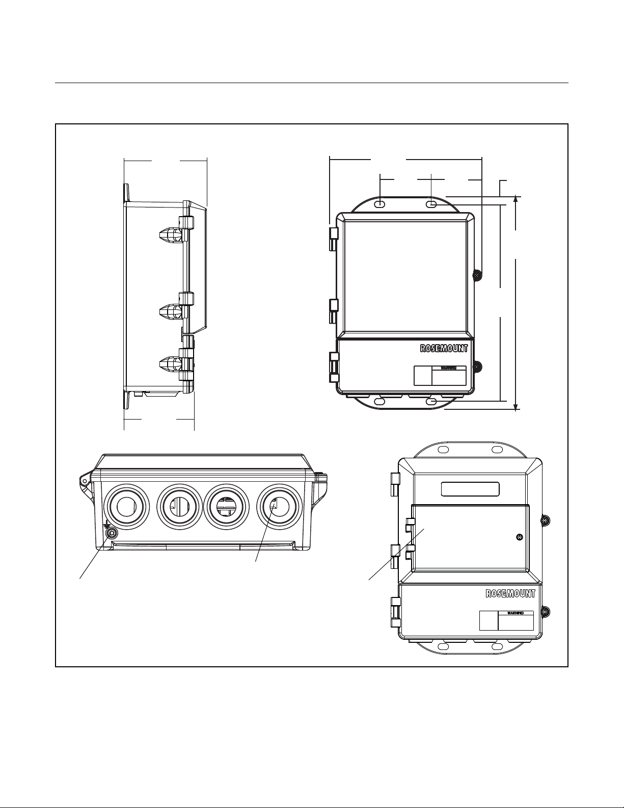
transmitter covers, and easy readability of the LOI screen (see Figure 2-1).
The transmitter should be mounted in a manner that prevents moisture in the
conduit from collecting in the transmitter.
The 8712 is mounted separately from the sensor, it
is not subject to limitations that might apply to the sensor.
2-2
Page 13
Reference Manual
4.31
(109)
LOI Keypad
Cover
9.01
(229)
11.15
(283)
2.81
(71)
3.11
(79)
12.02
(305)
0.44
(11)
Ground Lug
1
/2–14 NPT
Conduit
Connection
(4 Places)
WITH ST ANDARD COVER
NOTE
Dimensions are in inches (millimeters)
2.96
(75)
WITH LOI COVER
00809-0100-4664, Rev BA
January 2010
Figure 2-1. Rosemount 8712
Dimensional Drawing
Rosemount 8712
2-3
Page 14

Rosemount 8712
Reference Manual
00809-0100-4664, Rev BA
January 2010
Environmental Considerations
INSTALLATION PROCEDURES
To ensure maximum transmitter life, avoid excessive heat and vibration.
Typical problem areas:
• high-vibration lines with integrally mounted transmitters
• warm-climate installations in direct sunlight
• outdoor installations in cold climates.
Remote-mounted transmitters may be installed in the control room to protect
the electronics from the harsh environment and provides easy access for
configuration or service.
Rosemount 8712 transmitters require ex te rn al po we r an d th er e mu st be
access to a suitable power source.
Rosemount 8712 installation includes both detaile d mechanical and electrical
installation procedures.
Mount the Transmitter At a remote site the transmitter may be mounted on a pipe up to two inches in
diameter or against a flat surface.
Pipe Mounting
To mount the transmitter on a pipe:
1. Attach the mounting plate to the pipe using the mounting hardware.
2. Attach the 8712 to the mounting plate using the mounting screws.
Surface Mounting
To surface mount the transmitter:
1. Attach the 8712 to the mounting location using the mounting screws.
Identify Options and Configurations
The standard application of the 8712 includes a 4–20 mA output and control
of the sensor coils. Other applications may require one or more of the
following configurations or options:
• Multidrop Communications
• PZR (Positive Zero Return)
• Auxiliary Output
• Pulse Output
Additional options may apply. Be sure to identify those options and
configurations that apply to your situation, and keep a list of them nearby for
consideration during the installation and configuration procedures.
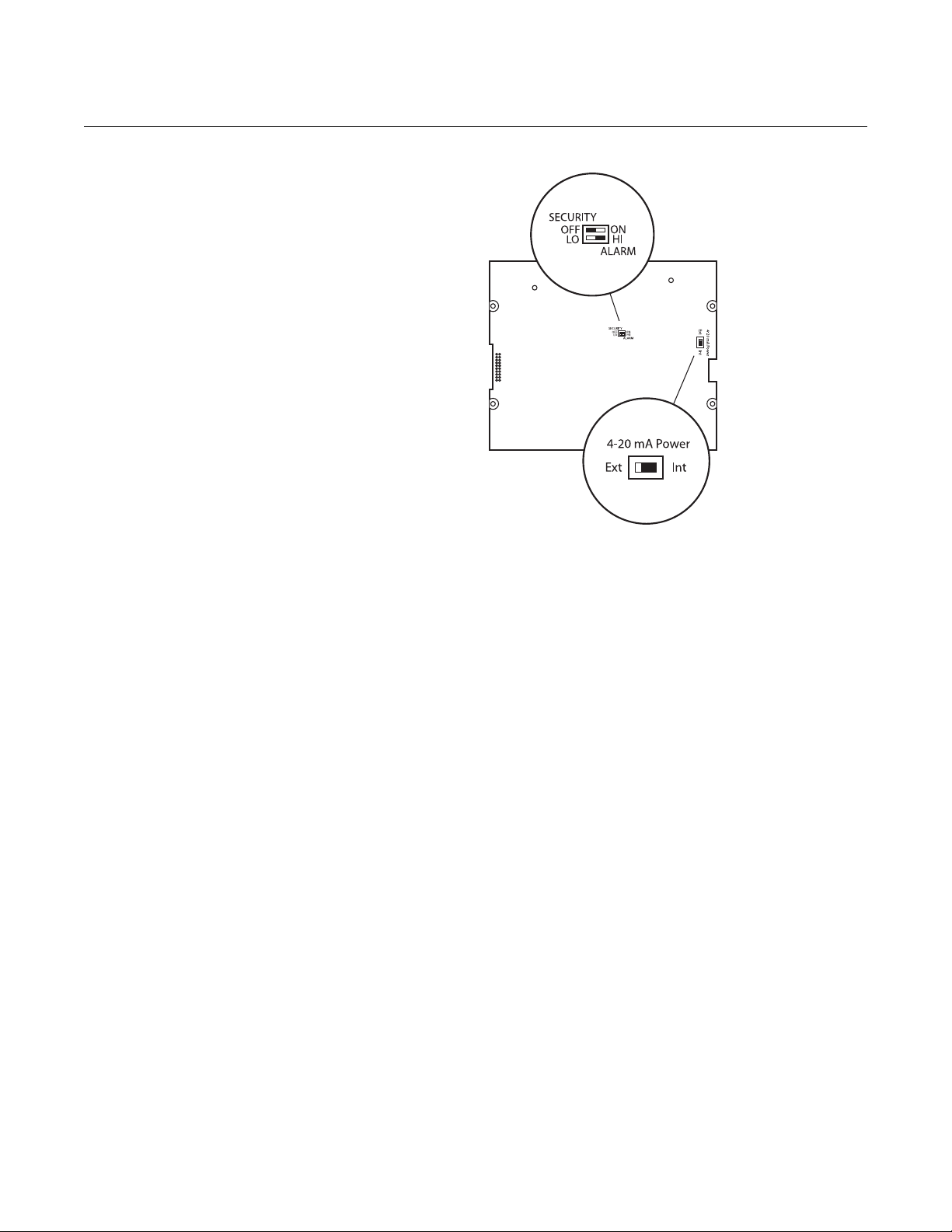
Hardware Switches The 8712 electronics board is equipped with
three user-selectable hardware switches. These switches set the Failure
Alarm Mode, Internal/External Analog Power, and Transmitter Security. The
standard configuration for these switches when shipped from the factory are
as follows:
Failure Alarm Mode: HIGH
Internal/External Analog Power: INTERNAL
Transmitter Security: OFF
2-4
Page 15

Reference Manual
00809-0100-4664, Rev BA
January 2010
Rosemount 8712
Changing Hardware Switch Settings
In most cases, it is not necessary to change the setting of the hardware
switches. If you need to change the switch settings, complete the steps
outlined in the manual.
Definitions of these switches and their functions are provided below. If you
determine that the settings must be changed, see below.
Failure Alarm Mode
If the 8712 experiences a catastrophic failure in the electronics, the current
output can be driven high (23.25 mA) or low (3.75 mA). The switch is set in
the HIGH (23.25 mA) position when it is shipped from the factory.
Internal/External Analog Power
The Rosemount 8712 4–20 mA loop may be powered internally
or by an external power supply. The internal/external power supply switch
determines the source of the 4–20 mA loop power.
Transmitters are shipped from the factory with the switch set
in the INTERNAL position.
The external power option is required for mu ltidrop configur ations. A 10–3 0 V
DC external supply is required and the 4-20mA power switch must be set to
“EXT” position. For further information on 4–20 mA external power, see
Connect 4–20 mA Loop External Power Source on page 2-9.
Transmitter Security
The security switch on the 8712 allows the user to lock out any configuration
changes attempted on the transmitter. No changes to the configuration are
allowed when the switch is in the ON position. The flow rate indication and
totalizer functions remain active at all times.
With the switch in the ON position, you may still access and review any of the
operating parameters and scroll through the available choices, but no actual
data changes are allowed. Transmitter security is set in the OFF position
when shipped from factory.
Changing Hardware Switch Settings
In most cases, it is not necessary to change the setting of the hardware
switches. If you need to change the switch settings, complete the steps
below:
NOTE
The hardware switches are located on the non-component side of the
electronics board and changing their settings requires opening the electronics
housing. If possible, carry out these procedures away from the plant
environment in order to protect the electronics.
1. Disconnect power to the transmitter.
2. Loosen the housing door screw and open the housing door.
3. Identify the location of each switch (see Figure 2-2).
4. Change the setting of the desired switches with a sm all scr ewd r iver.
5. Close the housing door and tighten the housing door screw.
2-5
Page 16
Rosemount 8712
Figure 2-2. Rosemount 8712
Electronics Board and Hardware
Switches
Reference Manual
00809-0100-4664, Rev BA
January 2010
Conduit Ports and Connections
Both the sensor and transmitter junction boxes have ports for 1/2-in. NPT
conduit connections. These connections should be made in accordance with
local or plant electrical codes. Unused ports should be sealed with metal
plugs. Proper electrical installation is necessary to prevent errors due to
electrical noise and interference. Separate conduits are not necessary for the
two cables, but a dedicated conduit line between each transmitter and sensor
is required. Shielded cable must be used for best results in electrically
noisy environments.
Example 1: Installing flanged sensors into an IP68 area. Sensors must be
installed with IP68 cable glands and cable to maintain IP68 rating. Unused
conduit connections must be properly sealed to prevent water ingress. For
added protection, dielectric gel can be used to pot the sensor terminal block.
Example 2: Installing flowmeters into explosion proof/flameproof areas.
Conduit connections and conduit must be rated for use in the hazardous area
to maintain flowmeter approval rating.
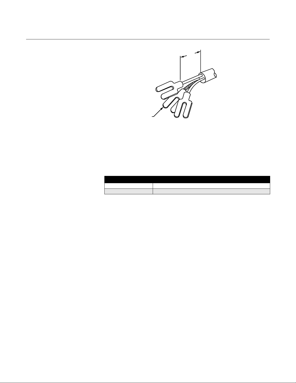
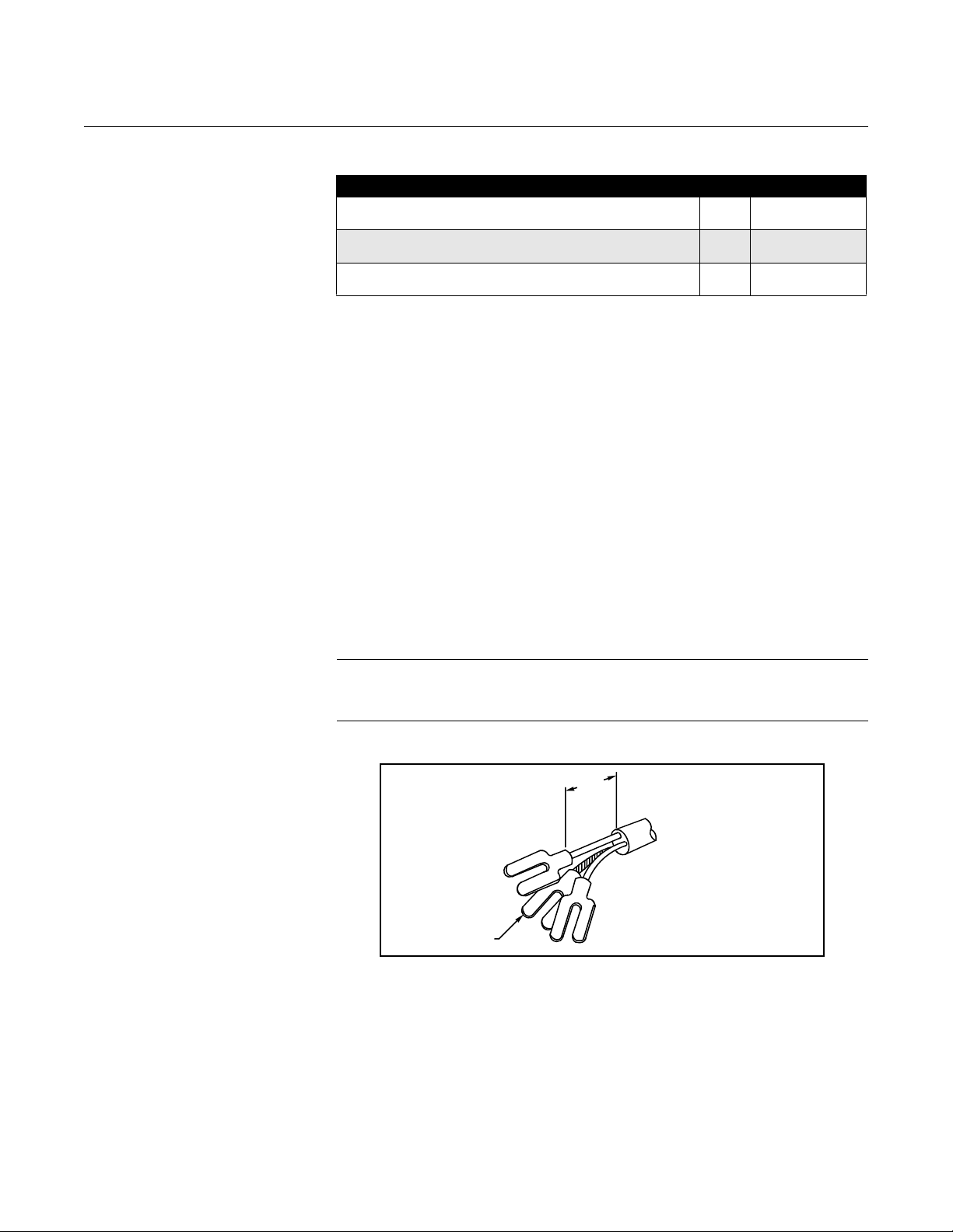
Conduit Cables Run the appropriate size cable through the conduit connections in your
magnetic flowmeter system. Run the power cable from the power source to
the transmitter. Run the coil drive and e lectrode cables between the flowmeter
and transmitter. Refer to Electrical Considerations for wire type. Prepare the
ends of the coil drive and electrode cables as shown in Figure 2-3. Limit the
unshielded wire length to 1-inch on both the electrode and coil drive cables.
Excessive lead length or failure to connect cable shields can create electrical
noise resulting in unstable meter readings.
• Installed signal wiring should not be run together an d should not be in
the same cable tray as AC or DC power wiring.
• Device must be properly grounded or earthed according to local
electric codes.
• Rosemount combination cable model number 08712-0752-0001 (ft) or
08712-0752-0003 (m) is required to be used to meet EMC
requirements.
2-6
Page 17
Reference Manual
NOTE
Dimensions are in
inches
(millimeters).
1.00
(26)
Cable Shield
Maximum Resis cetan
Supply Voltage 12– VDC
1amp
------------------------------------------------------------------------=
00809-0100-4664, Rev BA
January 2010
Rosemount 8712
Figure 2-3. Cable Preparation
Detail
Electrical Considerations Before making any electrical connections to the Rosemount 8712, consider
the following standards and be sure to have the pro per power supply, conduit,
and other accessories.
Transmitter Input Power
The 8712 transmitter is designed to be powered by 90-250 V AC, 50–60 Hz
or 12–42 V DC. The eight digit in the transmitter model number designates
the appropriate power supply requirement.
Model Number Power Supply Requirement
2 12-42 V DC
1 90-250 V AC
Supply Wire Temperature Rating
Use 12 to 18 AWG wire. For connections in ambient temperatures
exceeding 140 °F (60 °C), use wire rated to at least 194 °F (90 °C).
Disconnects
Connect the device through an external disconnect or circuit breaker.
Clearly label the disconnect or circuit breaker and locate it near the
transmitter.
Requirements for 90-250 V AC Power Supply
Wire the transmitter according to local electrical requirements for the supply
voltage. In addition, follow the supply wire and disconnect requirements on
page 2-9.
Requirements for 12-42 V DC Power Supply
Units powered with 12-42 V DC may draw up to 1 amp of cu rren t. As a result,
the input power wire must meet certain gauge requirements.
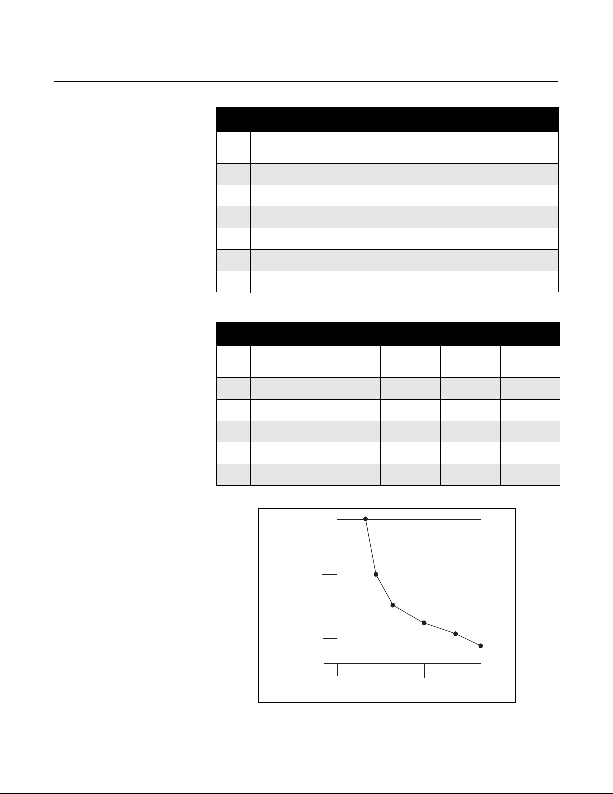
Figure 2-4 shows the surge current for each corresponding supply voltage.
For combinations not shown, you can calculate the maximum distance given
the supply current, the voltage of the source, and the minimum start-up
voltage of the transmitter, 12 V DC, using the following equation:
Use Table 2-1 and Table 2-2 to determine the maximum wire length allowable
for your power supply and maximum resistance.
2-7
Page 18
Rosemount 8712
1.0
0.8
0.6
0.4
0.2
0
0
10
20 30
40
50
Power Supply (Volts)
Supply Current (Amps)
Table 2-1. Length of Annealed
Copper (cu) Wires
Table 2-2. Length of
Hand-drawn Copper (cu) Wires
Types of Power
Supply Wires
Wire
Gauge
20 0.01015
18 0.006385
16 0.004016
14 0.002525
12 0.001588
10 0.000999
Wire
Gauge
18 0.00664
16 0.004176
14 0.002626
12 0.001652
10 0.01039
Annealed Cu
milliohms/ft
(milliohms/m)
(0.033292)
(0.020943)
(0.013172)
(0.008282)
(0.005209)
(0.003277)
Types of Power
Supply Wires
Annealed Cu
milliohms/ft
(milliohms/m)
(0.021779)
(0.013697)
(0.008613)
(0.005419)
(0.003408)
42 V DC
Supply ft (m)
1478
(451)
2349
(716)
3735
(1139)
5941
(1811)
9446
(2880)
15015
(4578)
Each Corresponding Power Supply Source
42 V DC
Supply ft (m)
2259
(689)
3592
(1095)
5712
(1741)
9080
(2768)
14437
(4402)
Reference Manual
00809-0100-4664, Rev BA
January 2010
Maximum Length of the Wire for Each
Corresponding Power Supply Source
30 V DC
Supply ft (m)
887
(270)
1410
(430)
2241
(683)
3564
(1087)
5668
(1728)
9009
(2747)
Maximum Length of the Wire for
30 V DC
Supply ft (m)
1355
(413)
2155
(657)
3427
(1045)
5448
(1661)
8662
(2641)
20 V DC
Supply ft (m)
394
(120)
626
(191)
996
(304)
1584
(483)
2519
(768)
4004
(1221)
20 V DC
Supply ft (m)
602
(184)
958
(292)
1523
(464)
2421
(738)
3850
(1174)
12.5 V DC
Supply ft (m)
25
(8)
39
(12)
62
(19)
99
(30)
157
(48)
250
(76)
12.5 V DC
Supply ft (m)
38
(11)
60
(18)
95
(29)
151
(46)
241
(73)
Figure 2-4. Supply Current
versus Input Voltage
2-8
Page 19
Reference Manual
Transmitter
Power Cable
AC Neutral or
AC Line or
AC Ground or
DC Ground
Fuse
00809-0100-4664, Rev BA
January 2010
Rosemount 8712
Installation Category The installation category for the Rosemount 8712 is
(Overvoltage) Category II.
Overcurrent Protection The Rosemount 8712 Flowmeter Transmitter requires overcurrent protection
of the supply lines. Maximum ratings of overcurrent devices are as follows:
Power System Fuse Rating Manufacturer
90–250 V AC 2 Amp, Quick Acting Bussman AGCI or Equivalent
12-42 V DC 3 Amp, Quick Acting Bussman AGC3 or Equivalent
OPTIONS, CONSIDERATIONS, AND PROCEDURES
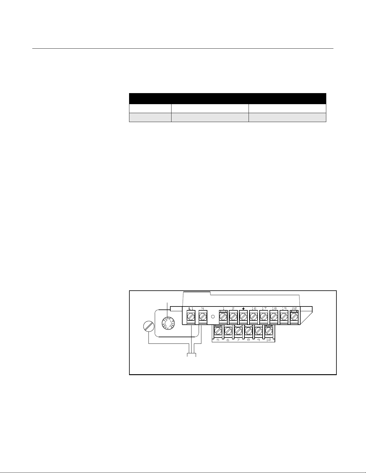
Connect Transmitter Power
Figure 2-5. Transmitter Power
Connections
If the application of the 8712 includes the use of options such as multidrop
communications, auxiliary output control, or pulse output, certain
requirements may apply in addition to those previously listed. Be prepared to
meet these requirements before attempting to install and operate the
Rosemount 8712.
To connect power to the transmitter, complete the following steps.
1. Ensure that the power source and connecting cable meet the
requirements outlined on page 2-8.
2. Turn off the power source.
3. Open the power terminal cover.
4. Run the power cable through the conduit to the transmitter.
5. Loosen the terminal guard for terminals L1 and N.
6. Connect the power cable leads as shown in Figure 2-5.
a. Connect AC Neutral or DC- to terminal N.
b. Connect AC Line or DC+ to terminal L1.
c. Connect AC Ground or DC Ground to the ground screw mounted
on the transmitter enclosure.
Connect 4–20 mA Loop External Power Source
The 4–20 mA output loop provides the process variable output from the
transmitter. Its signal may be powered internally or externally. The default
position of the internal/external analog power switch is in the internal position.
The user-selectable power switch is located on the electronics board.
2-9
Page 20

Rosemount 8712
–4–20 mA power
+4–20 mA power
Fuse
Reference Manual
00809-0100-4664, Rev BA
January 2010
Internal
The 4–20 mA analog power loop may be powered from the transmitter
itself. Resistance in the loop must be 1,000 ohms or less. If a Handheld
Communicator or control system will be used, it must be connected across
a minimum of 250 ohms resistance in the loop.
External
HART multidrop installations require a 10–30 V DC external power source
(see Multidrop Communications on page 3-16). If a Handheld
Communicator or control system is to be used, it must be connected
across a minimum of 250 ohms resistance in the loop.
To connect external power to the 4–20 mA loop, complete the
following steps.
1. Ensure that the power source and connecting cable meet the
requirements outlined above and in Electrical Co nsiderations on pa ge
2-7.
2. Turn off the transmitter and analog power sources.
3. Run the power cable into the transmitter.
4. Connect –DC to Terminal 8.
5. Connect +DC to Te rminal 7.
Figure 2-6. 4–20 mA Loop
Power Connections
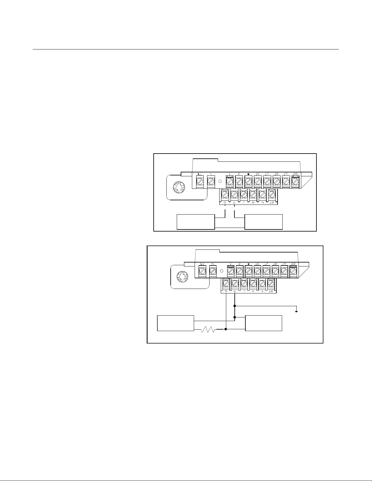
Connect Pulse Output Power Source
Refer to Figure 2-6 on page 2-10.
The pulse output function provides an isolated switch-closure frequency
signal that is proportional to the flow through the sensor . The signal is typically
used in conjunction with an external totalizer or control system. The following
requirements apply:
Supply Voltage: 5 to 24 V DC
Load Resistance: 1,000 to 100 k ohms (typical
Pulse Duration: 1.5 to 500 msec (adjustable), 50% duty cycle below 1.5 msec
Maximum Power: 2.0 watts up to 4,000 Hz and 0.1 watts at 10,000 Hz
Switch Closure: solid state switch
5 k)
2-10
Page 21
Reference Manual
Electro-mecha
nical Counter
5–28 V DC
Power
Supply
+
–
–
–
+ +
Electronic
Counter
5–28 V DC
Power
Supply
1k to 100 k
Typical 5 k
–
+
+
–
+
–
00809-0100-4664, Rev BA
January 2010
Figure 2-7. Connecting to a
Electromechanical
Totalizer/Counter
Rosemount 8712
The pulse output option requires an external power source . Complete the
following steps to connect an external power suppl y.
1. Ensure that the power source and connecting cable meet the
requirements outlined previously.
2. Turn off the transmitter and pulse output power sources.
3. Run the power cable to the transmitter.
4. Connect –DC to terminal 6.
5. Connect +DC to terminal 5.
Refer to Figure 2-7 and Figure 2-8.
Figure 2-8. Connecting to a
Electronic Totalizer/Counter
without Integral Power Supply
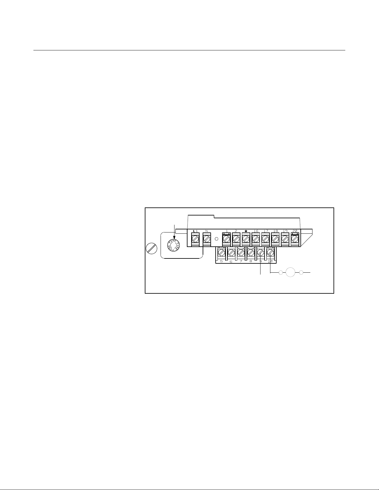
Connect Auxiliary Channel 1
Auxiliary channel 1 can be configured as either a digital input or a digital
output. When configured as an input, the following requirements apply:
Supply Voltage: 5 to 28V DC
Maximum Power: 2 watts
Switch Closure: optically isolated solid state switch
Maximum Impedance 2.5 k
When using channel 1 as a digital input, the power source and the control
relay must be connected to the transmitter. See Figu re 2-9 for more deta ils on
this connection.
2-11
Page 22
Rosemount 8712
DC–
DC+
Fuse
Control Relay
or Input
Reference Manual
00809-0100-4664, Rev BA
January 2010
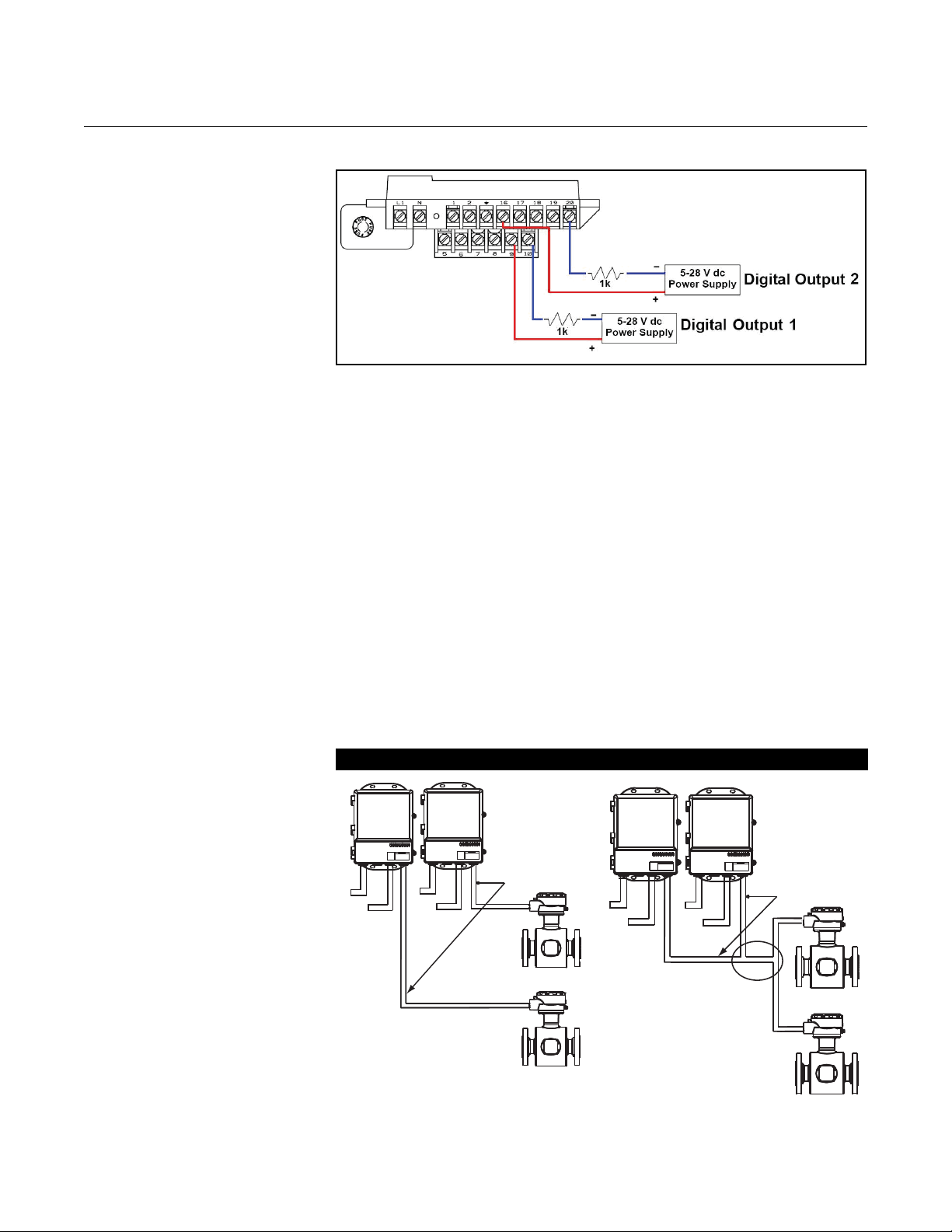
When configured as an output, the following requirements apply:
Supply Voltage: 5 to 28V DC
Maximum Power: 2 watts
Switch Closure: optically isolated solid state switch
When using channel 1 as a digital output, the power source must be
connected to the transmitter. See Figure 2-10 for more details on this
connection.
When connecting power to channel 1, complete the following steps:
1. Ensure that the power source and connecting cable meet the
requirements outlined previously.
2. Turn off the transmitter and auxiliary power sources.
3. Run the power cable to the transmitter.
4. Connect –DC to terminal 10.
5. Connect +DC to terminal 9.
Figure 2-9. Connect Digital Input
1 to Relay or Input to Control
System
Connect Auxiliary Channel 2
Auxiliary channel 2 is configured to provide a digital output based on the
configuration parameters set in the transmitter.
The following requirements apply to this channel:
Supply Voltage: 5 to 28V DC
Maximum Power: 2 watts
Switch Closure: optically isolated solid state switch
When connecting power to channel 2, complete the following steps:
1. Ensure that the power source and connecting cable meet the
requirements outlined previously.
2. Turn off the transmitter and auxiliary power sources.
3. Run the power cable to the transmitter.
4. Connect –DC to terminal 20.
5. Connect +DC to terminal 16.
2-12
See Figure 2-10 for more details on this connection.
Page 23
Reference Manual
Coil Drive
and
Electrode
Cables
Power
Power
Outputs
Outputs
Coil Drive
and
Electrode
Cables
Power
Outputs
Power
Outputs
00809-0100-4664, Rev BA
January 2010
Rosemount 8712
Figure 2-10. Connecting Digital
Outputs
SENSOR CONNECTIONS This section covers the steps required to physically install the transmitter
including wiring and calibration.
Rosemount Sensors To connect the transmitter to a non-Rosemount sensor, refer to the
appropriate wiring diagram in Appendix D: Wiring Diagrams. The calibration
procedure listed is not required for use with Rosemount sensors.
Transmitter to Sensor Wiring
Figure 2-11. Conduit Preparation
Flanged and wafer sensors have two conduit ports as shown in Figures 4-13,
4-14, 4-15, and 4-16. Either one may be used for both the coil drive and
electrode cables. Use the stainless steel plug that is provided to seal the
unused conduit port.
A single dedicated conduit run for the coil drive and electrode cables is
needed between a sensor and a remote transmitter. Bundled cables in a
single conduit are likely to create interference and noise problems in your
system. Use one set of cables per conduit run. See Figure 2-11 for proper
conduit installation diagram and Table 2-3 for recommended cable. For
integral and remote wiring diagrams refer to Figure 2-13.
Correct Incorrect
2-13
Page 24
Rosemount 8712
1.00
(26)
NOTE
Dimensions are in
inches (millimeters).
Cable Shield
Reference Manual
00809-0100-4664, Rev BA
January 2010
Table 2-3. Cable Requirements
Description Units Part Number
Signal Cable (20 AWG) Belden 8762, Alpha 2411 equivalent ftm08712-0061-0001
Coil Drive Cable (14 AWG) Belden 8720, Alpha 2442 equivalent ftm08712-0060-0001
Combination Signal and Coil Drive Cable (18 AWG)
(1) Combination signal and coil drive cable is not recommended for
high-signal magmeter system. For remote mount installati ons, combination signal and coil drive cable
should be limited to less than 300 ft. (100 m).
(1)
Rosemount recommends using the combination signal and coil drive for N5,
E5 approved sensors for optimum performance.
Remote transmitter installations require equal lengths of signal and coil drive
cables. Integrally mounted transmitters are factory wired and do not require
interconnecting cables.
Lengths from 5 to 1,000 feet (1.5 to 300 meters) may be specified, and will be
shipped with the sensor.
08712-0061-0003
08712-0060-0003
ftm08712-0752-0001
08712-0752-0003
Conduit Cables Run the appropriate size cable through the conduit connections in your
magnetic flowmeter system. Run the power cable from the power source to
the transmitter. Run the coil drive and e lectrode cables between the flowmeter
and transmitter.
Prepare the ends of the coil drive and electrode cables as shown in Figure
2-12. Limit the unshielded wire length to 1-inch o n both the ele ctrode and co il
drive cables.
NOTE
Excessive lead length or failure to connect cable shields can create electrical
noise resulting in unstable meter readings.
Figure 2-12. Cable Preparation
Detail
2-14
Page 25
Reference Manual
00809-0100-4664, Rev BA
January 2010
Rosemount 8712
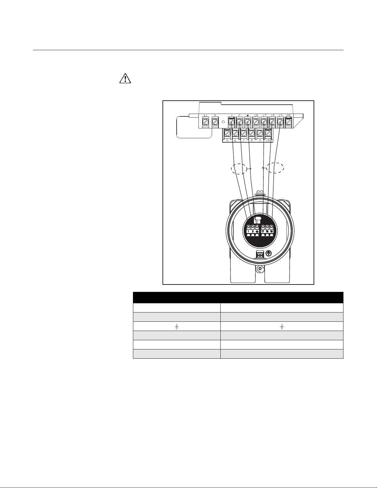
Sensor to Remote Mount Transmitter Connections
Figure 2-13. Wiring Diagram
Connect coil drive and electrode cables as shown in Figure 2-13.
Do not connect AC power to the sensor or to terminals 1 and 2 of the
transmitter, or replacement of the electronics board will be necessary.
Rosemount 8712 Transmitter Rosemount 8705/8707/8711/8721 sensors
11
2 2
17 17
18 18
19 19
2-15
Page 26

Rosemount 8712
Reference Manual
00809-0100-4664, Rev BA
January 2010
2-16
Page 27
Reference Manual
00809-0100-4664, Rev BA
January 2010
Rosemount 8712
Section 3 Configuration
Introduction . . . . . . . . . . . . . . . . . . . . . . . . . . . . . . . . . . . . . page 3-1
Installation Check and Guide . . . . . . . . . . . . . . . . . . . . . .page 3-1
Basic Features . . . . . . . . . . . . . . . . . . . . . . . . . . . . . . . . . . page 3-3
LOI Examples . . . . . . . . . . . . . . . . . . . . . . . . . . . . . . . . . . .page 3-4
Diagnostic Messages . . . . . . . . . . . . . . . . . . . . . . . . . . . . . page 3-6
Process Variables . . . . . . . . . . . . . . . . . . . . . . . . . . . . . . . .page 3-6
Basic Setup . . . . . . . . . . . . . . . . . . . . . . . . . . . . . . . . . . . . . page 3-8
INTRODUCTION This section covers basic operation, software functionality, and configuration
procedures for the Rosemount 8712 Magnetic Flowmeter Transmitter. For
information on connecting another manufacturer’s sensor , refer to “Universal
Sensor Wiring Diagrams” on page E-1.
The Rosemount 8712 features a full range of software functions for
configuration of output from the transmitter. Software functions are accessed
through the LOI, AMS, a Handheld Communicator, or a control system.
Configuration variables may be changed at any time and specific instructions
are provided through on-screen instructions.
INSTALLATION CHECK AND GUIDE
Table 3-1. Parameters
Basic Set-up Parameters Page
Review page 3-6
Process Variables page 3-6
Basic Setup page 3-8
Flow Units page 3-8
Range Values page 3-11
PV Sensor Calibration Number page 3-12
Totalizer Setup page 3-7
Use this guide to check new installations of Rosemount magnetic flowmeter
systems that appear to malfunction.
Before You Begin
www.rosemount.com
Page 28

Rosemount 8712
Reference Manual
00809-0100-4664, Rev BA
January 2010
Transmitter
Apply power to your system before making the following transmitter checks.
1. Verify that the correct sensor calibration number is entered in the
transmitter. The calibration number is listed on the sensor nameplate.
2. Verify that the correct sensor line size is entered in the transmitter.
The line size value is listed on the sensor nameplate.
3. Verify that the a nalog range of the transmitter matches the analog
range in the control system.
4. Verify that the forced analog output of the transmitter produces the
correct output at the control system.
Sensor
Be sure that power to your system is removed before beginning sensor
checks.
1. For horizontal flow inst a llations , ensu re that the ele ctrodes remain
covered by process fluid.
For vertical or inclined installations, ensure that the process fluid
is flowing up into the sensor to keep the electrodes covered by
process fluid.
2. Ensure that the grounding straps on the sensor are connected to
grounding rings, lining protectors, or the adjacent pipe flanges.
Improper grounding will cause erratic operation of the system.
Wiring
1. The signal wire and coil drive wire must be twisted shielded cable.
Emerson Process Management, Rosemount division. recommends
20 AWG twisted shielded cable for the electrodes and 14 AWG
twisted shielded cable for the coils.
2. The cable shield must be connected at both ends of the electrode and
coil drive cables. Connection of the shield at both ends is absolutely
necessary for proper operation.
3. The signal and coil drive wires must be separate cables, unless
Emerson Process Management specified combo cable is used.
4. The single conduit that houses both the signal and coil drive cables
should not contain any other wires.
Process Fluid
1. The process fluid conductivity should be 5 microsiemens
(5 micro mhos) per centimeter minimum.
2. The process fluid must be free of air and gasses.
3. The sensor should be full of process fluid.
LOCAL OPERATOR INTERFACE
3-2
Refer to Section 6 "Maintenance and Troubleshooting" for further information.
The optional Local Operator Interface (LOI) provides an operator
communications center for the 8712. By usin g th e LO I, th e op er at or can
access any transmitter function for changing configuration paramete r settings,
checking totalized values, or other functions. The LOI is integral to the
transmitter housing.
Page 29
Reference Manual
DISPLAY CONTROL TOTALIZER
TRANSMITTER PARAMETERS
DAT A
ENTRY
FLOW
RATE
TOTALIZE
START
STOP
READ
RESET
TUBE CAL
NO.
TUBE
SIZE
UNITS
AUX.
FUNCTION
ANALOG
OUTPUT
RANGE
PULSE
OUTPUT
SCALING
DAMPING XMTR
INFO
SHIFT
ENTER
INCR.
00809-0100-4664, Rev BA
January 2010
Rosemount 8712
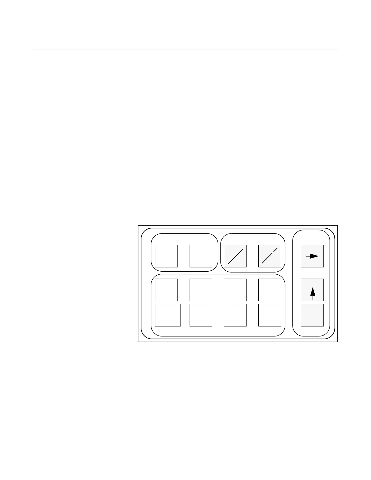
BASIC FEATURES The basic features of the LOI include display control, tot al izer, data entry, and
transmitter parameters. These features provide control of all transmitter
functions, see Figure 3-1.
Display Control Keys
The display control keys provide control over the variable displayed on the
LOI screen. Push FLOW RATE to display the process variable, or push
TOTALIZE to display the totalized value.
Totalizer Keys
The totalizer keys enable you to start, stop, read, and reset the totalizer.
Data Entry Keys
The data entry keys enable you to move the display cursor, incrementally
increase the value, or enter the selected value.
Transmitter Parameter Keys
The transmitter parameter keys provide direct access to the most common
transmitter parameters and stepped access to the advanced functions of the
8712 through the AUX. FUNCTION key.
Figure 3-1. Local Operator
Interface Keypad
Data Entry The LOI keypad does not have numerical keys. Numerical data is entered by
the following procedure.
1. Access the appropriate function.
2. Use SHIFT to highlight the digit you want to enter or change.
3. Use INCR. to change the highlighted value. For numerical data,
4. Use SHIFT to highlight other digits you want to change and
5. Press ENTER.
INCR. toggle through the digits 0–9, decimal point, and dash. For
alphabetical data, toggle through the letters of the alphabet A–Z,
digits 0–9, and the symbols l,&, +, -, *, /, $, @,%, and the blank
space. (INCR. is also used to toggle throu gh pre- determined ch oices
that do not require data entry.)
change them.
3-3
Page 30

Reference Manual
00809-0100-4664, Rev BA
Rosemount 8712
January 2010
Selecting Options To select pre-defined software options on the LOI, use the
following procedure:
1. Access the appropriate option.
2. Use SHIFT or INCR. to toggle between the applicable choices.
3. Press ENTER when the desired choice is displayed on the screen.
LOI EXAMPLES Use the TRANSMITTER PARAMETER keys shown in Figure 3-1 to change
the parameters, which are set in one of two ways, table values or select
values.
Table Values:
Parameters such as units, that are available from a predefined list
Select Values:
Parameters that consist of a user-created number or character string, such
as calibration number; values are entered one character at a time using
the data entry keys
Table Value Example Setting the sensor line size:
1. Press TUBE SIZE.
2. Press SHIFT or INCR. to increase (incrementa lly) the size to the next
value.
3. When you reach the desired size, press ENTER.
4. Set the loop to manual if necessary, and press ENTER again.
After a moment, the LCD will display the new tube size and the maximum flow
rate.
Select Value Example Changing the ANALOG OUTPUT RANGE:
1. Press ANALOG OUTPUT RANGE.
2. Press SHIFT to position the cursor.
3. Press INCR. to set the number.
4. Repeat steps 2 and 3 until desired number is displayed.
5. Press ENTER.
After a moment, the LCD will display the new analog output range.
Table 3-2. LOI Data Entry Keys and Functions
Data Entry Keys Function Performed
Shift
Increment
Enter Stores the displayed value previously selected with the SHIFT and INCR. keys
Display Control Keys Function Performed
Flow Rate Displays the user-selected parameters for flow indication
Totalize Displays the present totalized output of the transmitter, and activates the Totalizer group of keys
Start/Stop Starts the totalizing display if it is stopped, and stops the display if it is running
Read/Reset Resets the net totalizing display to zero if it is stopped, and halts the display if the display is running
• Moves the blinking cursor on the display one character to the right
• Scrolls through available values
• Increments the character over the cursor by one
• Steps through all the digits, letters, and symbols that are applicable to the present operation
• Scrolls through available values
The choices, Forward and Reverse totals or Net and Gross totals, are selected in Auxiliary Functions
3-4
Page 31

Reference Manual
00809-0100-4664, Rev BA
January 2010
Table 3-2. LOI Data Entry Keys and Functions
Transmitter Parameters
Keys
Tube Cal No. Identifies the calibration number when using Rosemount sensors, or other manufacturers’ sensors calibrated
Tube Size Specifies the sensor size and identifies the corresponding maximum flow (0.1 - through 80-inch line sizes)
Units Specifies the desired units:
Auxiliary Functions Function
Analog Output Range Sets the desired 20 mA point – must set the sensor size first
Pulse Output Scaling Sets one pulse to a selectable number of volume units – must set the sensor size first
Damping Sets response time (single pole time constant), in seconds, to a step change in flow rate
Transmitter Information Allows you to view and change useful information about the transmitter and sensor
Empty Pipe Tuning Allowable range 3.0 - 2000.0
Function Performed
at the Rosemount factory
Gal/Min Liters/Min
ImpGal/Min CuMeter/Hr
Ft/Sec Meters/Sec
Special (user defined)
For a complete list of available units, see Table 3-3 on page 3-9
Run 8714i
Operating Mode
Coil Pulse Mode
Flow rate Display
Totalizer Display
Totalizer Units
Signal Processing
Special Units
Process Density
DI/DO 1 Config
Digital Output 2
Flow Limit 1
Flow Limit 2
Totalizer Limit
Diagnostic Status Alert
Reverse Flow Enable
Licensed Options
License Key
Diagnostics Enable
8714i Setup
Re-signature Sensor
Recall Last Signature
Empty Pipe
Universal Auto Trim
Low Flow Cutoff
Pulse Width
Analog Output Zero
Analog Output Test
Pulse Output Test
Transmitter Test
4–20 mA Output Trim
Auto Zero
Electronics Trim
Options
Runs the meter verification diagnostic
Normal or Filter
5 or 37 Hz
Flow–% Span, Flow–Totalize, %Span–Totalize
Forward–Reverse or Net–Gross
Configure the totalizer units of measure
On/Off
Volume units, base volume unit s , conversion, time base, rate unit s
Required for units of mass flow
Configure Auxiliary Channel 1
Configure Auxiliary Channel 2
Configure Flow Limit 1 Alert
Configure Flow Limit 2 Alert
Configure Totalizer Limit Alert
Configure Diagnostic Status Alert
Reverse Flow/Zero Flow
On/Off
Field license advanced functionality
Turn diagnostics On/Off
Configure test criteria parameters
Base line sensor characteristics
Recall previous signature values
Configure empty pipe diagnostic parameters
In-process Sensor Calibration
0.01 ft/s to 1 ft/s
Pulse Width
4 mA Value
Analog Output Loop Test
Pulse Output Loop Test
Test the Transmitter
Adjust the 4–20 mA Output
Zero Sensor for 37 Hz Coil Drive Operation
Transmitter Calibration
Rosemount 8712
3-5
Page 32

Rosemount 8712
Reference Manual
00809-0100-4664, Rev BA
January 2010
DIAGNOSTIC MESSAGES
The following error messages may appear on the LOI screen. See
“Maintenance and Troubleshooting” on page 6-1 for potential causes and
corrective actions for these errors:
• Electronics Failure
• Coil open circuit
• Digital trim failure
• Auto zero failure
• Auto trim failure
• Flow rate >42 ft/sec
• Analog out of range
• PZR activated
• Empty pipe
• Reverse flow
• Reverse flow indicator
(A flashing letter “R” on the LOI indicates a reverse flow)
• Totalizer indicator
(A flashing letter “T” on the LOI indicates to totalizer is activated)
Review The 8712 includes a capability that enables you to review the configuration
Fast Keys 1, 5
variable settings.
The flowmeter configuration parameters set at the factory should be reviewed
to ensure accuracy and compatibility with your particular application of the
flowmeter.
NOTE
If you are using the LOI to review variables, each variable must be accessed
as if you were going to change its setting. The value displayed on the LOI
screen is the configured value of the variable.
PROCESS VARIABLES The process variables measure flow in several ways that reflect your needs
Fast Keys 1, 1
and the configuration of your flowmeter. When commissioning a flowmeter,
review each process variable, its function and output, and take corrective
action if necessary before using the flowmete r in a proc es s application
Process Variable (PV) – The actual measured flow rate in the line. Use the
Process Variable Units function to select the units for yourapplication.
Percent of Range – The process variable as a percentage of the Analog
Output range, provides an indication where the current flow of the meter is
within the configured range of the flowmeter. For example, the Analog Output
range may be defined as 0 gal/min to 20 gal/min. If the measured flow is 10
gal/min, the percent of range is 50 percent.
Analog Output – The analog output variable provides the analog value for the
flow rate. The analog output refers to the industry standar d output in the 4–20
mA range.
Totalizer Setup – Provides a reading of the total flow of the flowmeter since
the totalizer was last reset. The totalizer value should be zero during
commissioning on the bench, and the units should reflect the volume units of
the flow rate. If the totalizer value is not zero, it may need to be reset. This
function also allows for configuration of the totalizer parameters.
3-6
Pulse Output – The pulse output variable provides the pulse value for the flow
rate.
Page 33

Reference Manual
00809-0100-4664, Rev BA
January 2010
Rosemount 8712
PV - Primary Variable The Primary Variable shows the current measured flow rate. This value
Fast Keys 1, 1, 1
LOI Key FLOW RATE
determines the analog output from the transmitter.
PV -% Range The PV% Range shows where in the flow range the current flow value is as a
Fast Keys 1, 1, 2
percentage of the configured span.
PV - Analog Output The PV Analog Output displays the mA output of the transmitter
Fast Keys 1, 1, 3
corresponding to the measured flow rate.
Totalizer Setup The Totalizer Setup menu allows for the viewing and configuration of the
Fast Keys 1, 1, 4
LOI Key AUX. FUNCTION
totalizer parameters.
Totalizer Units
Fast Keys 1, 1, 4, 1
LOI Key AUX. FUNCTION
Totalizer units allow for the configuration of the units that the totalized value
will be displayed as. These units are independent of the flow units.
Measured Gross Total
Fast Keys 1, 1, 4, 2
LOI Key TOTALIZE
Measured gross total provides the output reading of the tot alizer. This value is
the amount of process fluid that has passed through the flowmeter since the
totalizer was last reset.
NOTE
To reset the measured gross total value, the line size must be changed.
Measured Net Total
Fast Keys 1, 1, 4, 3
LOI Key TOTALIZE
Measured net total provides the output reading of the totalizer. This value is
the amount of process fluid that has passed through the flowmeter since the
totalizer was last reset. When reverse flow is enabled, th e net tota l represent s
the difference between the total flow in the forward dir ection less the tot al flow
in the reverse direction.
Measured Reverse Total
Fast Keys 1, 1, 4, 4
LOI Key TOTALIZE
Measured reverse total provides the output reading of th e tota lizer. This value
is the amount of process fluid that has passed through the flowmeter in the
reverse direction since the totalizer was last reset. This value is only totalized
when reverse flow is enabled.
Start Totalizer
Fast Keys 1, 1, 4, 5
LOI Key START/STOP
Start totalizer starts the totalizer counting from its current value.
3-7
Page 34

Reference Manual
00809-0100-4664, Rev BA
Rosemount 8712
Stop Totalizer
Fast Keys 1, 1, 4, 6
LOI Key START/STOP
Stop totalizer in terrupts the totalizer count until it is restarted again. This
feature is often used during pipe cleaning or other main te na nce operations.
Reset Totalizer
Fast Keys 1, 1, 4, 7
LOI Key READ/RESET
Reset totalizer resets the net totalizer value to zero. The totalizer must be
stopped before resetting.
NOTE
The totalizer value is saved in the Non-Volatile memory of the electronics
every three seconds. Should power to the transmitter be interrupted, the
totalizer value will start at the last saved value when power is re-applied.
Pulse Output The Pulse Output displays the current value of the pulse signal.
Fast Keys 1, 1, 5
January 2010
BASIC SETUP The basic configuration functions of the Rosemount 8712 must be set for all
Fast Keys 1, 3
applications of the transmitter in a magnetic flowmeter system. If your
application requires the advanced functionality features of the Rosemount
8712, see Section 4 "Operation" of this manual.
Tag Tag is the quickest and shortest way of identifying and distinguishing between
Fast Keys 1, 3, 1
LOI Key XMTR INFO
transmitters. Transmitters can be tagged according to the requirements of
your application. The tag may be up to eight characters long.
Flow Units Flow Units set the output units for the Primary Variable which controls the
Fast Keys 1, 3, 2
analog output of the transmitter.
Primary Variable Units
Fast Keys 1, 3, 2, 1
LOI Key UNITS
The Primary Variable Units specifies the format in which the flow rate will be
displayed. Units should be selected to meet your particular metering needs.
3-8
Page 35

Reference Manual
00809-0100-4664, Rev BA
January 2010
Table 3-3. Options for Flow
Rate Units
Rosemount 8712
• ft/sec • B31/sec (1 Barrel = 31.5 gallons)
•m/sec • B31/min (1 Barrel = 31.5 gallons)
• gal/sec • B31/hr (1 Barrel = 31.5 gallons)
• gal/min • B31/day (1 Barrel = 31.5 gallons)
• gal/hr • lbs/sec
• gal/day •lbs/min
•l/sec •lbs/hr
•l/min • lbs/day
• l/hr • kg/sec
• l/day •kg/min
3
•ft
/sec • kg/hr
•ft3/min • kg/day
3
•ft
/hr • (s)tons/min
•ft3/day • (s)tons/hr
3
/sec • (s)tons/day
•m
•m3/min • (m)tons/min
3
/hr • (m)tons/hr
•m
•m3/day • (m)tons/day
• Impgal/sec • Special (User Defined, see
• Impgal/min
• Impgal/hr
• Impgal/day
• B42/sec (1 Barrel = 42 gallons)
• B42/min (1 Barrel = 42 gallons)
• B42/hr (1 Barrel = 42 gallons)
• B42/day (1 Barrel = 42 gallons)
“Special Units” on page 3-9)
Special Units
Fast Keys 1, 3, 2, 2
LOI Key AUX. FUNCTION
The Rosemount 8712 provides a selection of standard u nit configurations that
meet the needs of most applications (see “Flow Units” on page 3-8). If your
application has special needs and the standard configurations do not apply,
the Rosemount 8712 provides the flexibility to configure the transmitter in a
custom-designed units format using the special units variable.
Special Volume Unit
Fast Keys 1, 3, 2, 2, 1
Special volume unit enables you to display the volume unit format to which
you have converted the base volume units. For example, if the desired special
units are cubic cm/min, the special volume vari able can be repr esente d as cc
or cm3. The volume units variable is also used in totalizing the special units
flow.
3-9
Page 36

Rosemount 8712
Reference Manual
00809-0100-4664, Rev BA
January 2010
Base Volume Unit
Fast Keys 1, 3, 2, 2, 2
Base volume unit is the unit from which the conversion is being made. Set this
variable to the appropriate option.
Conversion Number
Fast Keys 1, 3, 2, 2, 3
The special units conversion number is used to convert base units to special
units. For a straight conversion of volume units from one to another, the
conversion number is the number of base units in the new unit. For example,
if you are converting from liters to cm3 and there are 0.001 liters in a cm3, the
conversion factor is 0.001.
Base Time Unit
Fast Keys 1, 3, 2, 2, 4
Base time unit provides the time unit from which to calculate the special units.
For example, if your special units is a volume per minute, select minutes.
Special Flow Rate Unit
Fast Keys 1, 3, 2, 2, 5
Special flow rate unit is a format variable that provides a record of the units to
which you are converting. The Handheld Communicator will display a special
units designator as the units format for your primary variable. The actual
special units setting you define will not appear. Four characters are available
to store the new units designation. The 8712 LOI will display the four
character designation as configured.
Example
To display flow in cubic cm per minute, and one cm3 is equal to 0.001 liters,
the procedure would be:
Set the Volume Unit to cm3 or cc.
Set the Base Volume Unit to liters.
Set the Input Conversion Number to 0.001.
Set the Time Base to Min.
Set the Rate Unit to CC/M.
Line Size The line size (sensor size) must be set to match the actual sensor connected
Fast Keys 1, 3, 3
LOI Key TUBE SIZE
to the transmitter. The size must be specified in inches according to the
available sizes listed below. If a value is entered from a control system or
Handheld Communicator that does not match one of these figures, the value
will go to the next highest option.
The line size (inches) options are as follows:
3-10
0.1, 0.15, 0.25, 0.30, 0.50, 0.75, 1, 1.5, 2, 2.5, 3, 4, 6, 8, 10, 12, 14,
16, 18, 20, 24, 28, 30, 32, 36, 40, 42, 44, 48, 54, 56, 60, 64, 72, 80
Page 37

Reference Manual
00809-0100-4664, Rev BA
January 2010
Rosemount 8712
PV URV (Upper Range Value)
Fast Keys 1, 3, 4
LOI Key ANALOG
OUTPUT RANGE
PV LRV (Lower Range Value)
Fast Keys 1, 3, 5
LOI Key AUX. FUNCTION
The upper range value (URV), or analog output range, is preset to 30 ft/s at
the factory . The units that appear will be the same as those selected under the
units parameter.
The URV (20 mA point) can be set for both forward or reverse flow rate. Flow
in the forward direction is represented by positive values and flow in the
reverse direction is represented by negative values. The URV can be any
value from –39.3 ft/s to +39.3 ft/s (-12 m/ s to +12 m/s) , as long as it is at least
1 ft/s (0.3 m/s) from the lower range value (4 mA point). The URV can be set
to a value less than the lower range value. This will cause the transmitter
analog output to operate in reverse, with the current increasing for lower (or
more negative) flow rates.
NOTE
Line size, special units, and density must be selected prior to configuration of
URV and LRV.
Set the lower range value (LRV), or analog output zero, to change the size of
the range (or span) between the URV and LRV. Under normal circumstances,
the LRV should be set to a value near the minimum expected flow rate to
maximize resolution. The LRV must be between
–39.3 ft/s to +39.3 ft/s (-12 m/s to +12 m/s).
NOTE
Line size, special units, and density must be selected prior to configuration of
URV and LRV.
Example
If the URV is greater than the LRV, the analog output will saturate at 3.9 mA
when the flow rate falls below the selected 4 mA point.
The minimum allowable span between the URV and LRV is 1 ft/s (0.3 m/s).
Do not set the LRV within 1 ft/s (0.3 m/s) of the 20 mA point. For example, if
the URV is set to 15.67 ft /s (4.8 m/s) and if the desired URV is greater than
the LRV, then the highest allowable analog zero setting would be 14.67 ft/s
(4.5 m/s). If the desired URV is less than the LRV, then the lowest allowable
LRV would be 16.67 ft/s (5.1 m/s).
3-11
Page 38

Reference Manual
00809-0100-4664, Rev BA
Rosemount 8712
January 2010
Calibration Number The sensor calibration number is a 16-digit number used to identify sensors
Fast Keys 1, 3, 6
LOI Key TUBE CAL NO.
calibrated at the Rosemount factory. The calibration number is also printed
inside the sensor terminal block or on the sensor name plate. The number
provides detailed calibration information to the Rosemount 8712. To function
properly within accuracy specifications, the number stored in the transmitter
must match the calibration number on the sensor exactly.
NOTE
Sensors from manufacturers other th an Rosem ou nt Inc. can als o be
calibrated at the Rosemount factory. Check the sensor for Rosemount
calibration tags to determine if a 16-digit calibration number exists for your
sensor.
NOTE
Be sure the calibration number reflects a calibration to a Rosemount
reference transmitter. If the calibration number was generated by a means
other than a certified Rosemount flow lab, accuracy of the system may be
compromised.
If your sensor is not a Rosemount sensor and was not calibrated at the
Rosemount factory, contact your Rosemount representative for assistance.
If your sensor is imprinted with an eight-digit number or a k-factor, check in
the sensor wiring compartment for the sixteen-digit calibration number. If
there is no serial number, contact the factory for a proper conversion.
PV Damping Adjustable between 0.0 and 256 seconds
Fast Keys 1, 3, 7
LOI Key DAMPING
PV Damping allows selection of a response time, in seconds, to a step change in flow rate. It is most often used to smooth fluctuations in output.
3-12
Page 39

Reference Manual
00809-0100-4664, Rev BA
January 2010
Rosemount 8712
Section 4 Operation
Introduction . . . . . . . . . . . . . . . . . . . . . . . . . . . . . . . . . . . . . page 4-1
Diagnostics . . . . . . . . . . . . . . . . . . . . . . . . . . . . . . . . . . . . .page 4-1
Basic Diagnostics . . . . . . . . . . . . . . . . . . . . . . . . . . . . . . . .page 4-2
Advanced Diagnostics . . . . . . . . . . . . . . . . . . . . . . . . . . . .page 4-7
Advanced Configuration . . . . . . . . . . . . . . . . . . . . . . . . . . page 4-16
Detailed Setup . . . . . . . . . . . . . . . . . . . . . . . . . . . . . . . . . . . page 4-16
INTRODUCTION This section contains information for advanced configuration parameters and
diagnostics.
The software configuration settings fo r the Rosemount 8712 can be accesse d
through a HART-based communicator, Local Operator Interface (LOI), or
through a control system. The software functions for the Field Communicator
are described in detail in this section of the manual. It provides an overview
and summary of communicator functions. For more complete instructions, see
the communicator manual. Before operating the Rosemount 871 2 in an actual
installation, you should review all of the factory set configuration data to
ensure that they reflect the current application.
DIAGNOSTICS Diagnostics are used to verify that the transmitter is functioning properly, to
Field Comm. 1, 2
assist in troubleshooting, to identify potential causes of error messages, and
to verify the health of the transmitter and sensor. Diagnostic tests can be
initiated through the use of a HART-based communications device, the Local
Operator Interface, or through the control system.
Rosemount offers several different diagnostic suites providing various
functionality.
Standard diagnostics included with every Rosemount 8712 transmitter are
Empty Pipe detection, Electronics Temperature monitoring, Coil Fault
detection, and various loop and transmitter tests.
Advanced diagnostics suite option one (DA1 op tion) con tains adva nc ed
diagnostics for High Process Noise detection and Grounding and Wiring fault
detection.
Advanced diagnostics suite option two (DA2 option) contains advanced
diagnostics for the 8714i Meter Verification. This diagnostic is used to verify
the accuracy and performance of the magnetic flowmeter installation.
Diagnostic Controls The diagnostic controls menu provides a centralized location for enabling or
Field Comm. 1, 2, 1
LOI Key AUX. FUNCTION
disabling each of the diagnostics that are available. Note that for some
diagnostics to be available, a diagnostics suite package is required.
www.rosemount.com
Page 40

Rosemount 8712
Reference Manual
00809-0100-4664, Rev BA
January 2010
Empty Pipe
Field Comm. 1, 2, 1, 1
Turn the empty pipe diagnostic on or off as required by the application. For
more details on the empty pipe diag nostic, see Appendix C: "Diagnostics".
High Process Noise
Field Comm. 1, 2, 1, 2
Turn the high process noise diag nostic on or off as required by the
application. For more details on the high process noise diagno stic , see
Appendix C: "Diagnostics".
Grounding / Wiring
Field Comm. 1, 2, 1, 3
Turn the grounding / wiring diagnostic on or of f as re quired by the application.
For more details on the grounding / wiring diagnostic, see Appendix C:
"Diagnostics".
Electronics Temperature
Field Comm. 1, 2, 1, 4
Turn the electronics temperature diagnostic on or off as required by the
application. For more details on the electronics temperature diagnostic, see
Appendix C: "Diagnostics".
Basic Diagnostics Th e basic diagnostics menu con tain s all of the st an dard diagno stics and test s
Field Comm. 1, 2, 2
that are available in the 8712 transmitter.
Self Test
Field Comm. 1, 2, 2, 1
LOI Key AUX. FUNCTION
The transmitter test initiates a series of diagnostic tests that are not performed
continuously during normal operation. It performs the following tests:
• Display Test
•RAM Test
•PROM Test
During the entire test, all outputs respond to flow signal. The test requires
about ten seconds to complete.
AO Loop Test
Field Comm. 1, 2, 2, 2
LOI Key AUX. FUNCTION
The AO Loop test allows you to drive the transmitter output to a desired
electrical current output on terminals 1 and 2. The user then has the ability to
independently measure the actual loop current against the desired level set
by the transmitter. On the LOI, the test will end after five minutes if the
transmitter is not returned to normal operation manually.
4-2
4 mA
Field Comm. 1, 2, 2, 2, 1
Fix the analog loop current at 4 mA.
Page 41

Reference Manual
00809-0100-4664, Rev BA
January 2010
Rosemount 8712
20 mA
Field Comm. 1, 2, 2, 2, 2
Fix the analog loop current at 20 mA.
Simulate Alarm
Field Comm. 1, 2, 2, 2, 3
Send the analog output into an alarm mA value. Actual mA value depends o n
the alarm configuration.
• Rosemount Standard High Alarm – 22.6 mA
• Rosemount Standard Low Alarm – 3.75 mA
• Namur Compliant High Alarm – 22.6 mA
• Namur Compliant Low Alarm – 3.5 mA
Other
Field Comm. 1, 2, 2, 2, 4
Fix the analog loop current to some other mA va lue between 3 .5 mA and 23.0
mA.
End
Field Comm. 1, 2, 2, 2, 5
This command cancels the analog loop test and returns the analog output
back into normal operating mode.
Pulse Output Loop Test
Field Comm. 1, 2, 2, 3
LOI Key AUX. FUNCTION
The Pulse Output Loop Test allows you to drive the frequency output at
terminals 3 and 4 to a desired value. The user then has the ability to compare
the pulse output value measured by auxiliary equipment to the desired pulse
output level set by the transmitter. On the LOI the test will end after five
minutes if the transmitter is not returned to normal operation manually.
Select Value
Field Comm. 1, 2, 2, 3, 1
Set the value of the pulse output for the test to a value between 1 pulse/day to
10,000 Hz.
End
Field Comm. 1, 2, 2, 3, 2
This command cancels the pulse output loop test and returns the pulse output
back into normal operating mode.
Tune Empty Pipe
Field Comm. 1, 2, 2, 4
LOI Key AUX. FUNCTION
Empty Pipe allows you to view the current value and configure the diagnostic
parameters. For more detail on this p arameter see Appendix C: "Diagnostics".
Empty Pipe Value
Field Comm. 1, 2, 2, 4, 1
LOI Key AUX. FUNCTION
Read the current Empty Pipe Value. This number is a unitless number and is
calculated based on multiple installation and process variables. For more
detail on this parameter see Appendix C: "Diagnostics".
4-3
Page 42

Rosemount 8712
Reference Manual
00809-0100-4664, Rev BA
January 2010
Empty Pipe Trigger Level
Field Comm. 1, 2, 2, 4, 2
LOI Key AUX. FUNCTION
Limits: 3 to 2000
Configure the threshold limit that the empty pipe value must exceed before
the diagnostic alert activates. Default from the factory is set to 100. For more
detail on this parameter see Appendix C: "Diagnostics".
Empty Pipe Counts
Field Comm. 1, 2, 2, 4, 3
LOI Key AUX. FUNCTION
Limits: 5 to 50
Configure the number of consecutive times that the empty pipe value must
exceed the empty pipe trigger level before the diagnostic alert activates.
Counts are taken at 1.5 second intervals. Default from the factory is set to 5.
For more detail on this parameter see Appendix C: "Diagnostics".
Electronics Temperature
Field Comm. 1, 2, 2, 5
LOI Key XMTR INFO
Electronics Temperature allows you to view the current value for the
electronics temperature.
Flow Limit 1
Field Comm. 1, 2, 2, 6
LOI Key AUX. FUNCTION
Configure the Parameters that will determine the criteria for activating a HART
alert if the measured flow rate falls within a set of configured criteria. This
functionality can be used for operating simple batching operations or
generating alerts when cert ain flow co nditions are met. This parameter can be
configured as a discrete output if the transmitter was ordered with auxiliary
outputs enabled (option code AX), or if this functionality has been licensed in
the field.
Control 1
Field Comm. 1, 2, 2, 6, 1
Turns the Flow Limit 1 ON or OFF.
ON – The transmitter will generate a HART alert when the defined
conditions are met. If a digital output is configured for Flow Limit 1, the
digital output will activate when the conditions for mode 1 are met.
OFF – The transmitter will not generate a HART alert for the Flow Limit 1.
Mode 1
Field Comm. 1, 2, 2, 6, 2
Mode that determines when the Flow Limit 1 HART Alert will activate.
> High Limit – The HART Alert will activate when the measured flow rate
exceeds the High Limit 1 set point.
4-4
< Low Limit – The HART Alert will activate when the measured flow rate
falls below the Low Limit 1 set point.
Page 43

Reference Manual
00809-0100-4664, Rev BA
January 2010
Rosemount 8712
In Range – The HART Alert will activate when the measured flow rate is
between the High Limit 1 and Low Limit 1 set points.
Out of Range – The HART Alert will activate when the measured flow rate
exceeds the High Limit 1 set point or falls below the Low Limit 1 set point.
High Limit 1
Field Comm. 1, 2, 2, 6, 3
Set the flow rate value that corresponds to the high limit set point for the Flow
Limit 1 alert.
Low Limit 1
Field Comm. 1, 2, 2, 6, 4
Set the flow rate value that corresponds to the low limit set point for the Flow
Limit 1 alert.
Flow Limit Hysteresis
Field Comm. 1, 2, 2, 6, 5
Set the hysteresis band for the flow limit to determine how quickly the
transmitter comes out of Alert status. This hysteresis value is used for both
Flow Limit 1 and Flow Limit 2.
Flow Limit 2
Field Comm. 1, 2, 2, 7
LOI Key AUX. FUNCTION
Configure the Parameters that will determine the criteria for activating a HART
alert if the measured flow rate falls within a set of configured criteria. This
functionality can be used for operating simple batching operations or
generating alerts when cert ain flow co nditions are met. This parameter can be
configured as a discrete output if the transmitter was ordered with auxiliary
outputs enabled (option code AX), or if this functionality has been licensed in
the field. If a digital output is configured for Flow Limit 1, the digital output will
activate when the conditions for mode 1 are met.
Control 2
Field Comm. 1, 2, 2, 7, 1
Turns the Flow Limit 2 HART Alert ON or OFF.
ON – The transmitter will generate a HART alert when the defined
conditions are met.
OFF – The transmitter will not generate a HART alert for the Flow Limit 2.
Mode 2
Field Comm. 1, 2, 2, 7, 2
Mode that determines when the Flow Limit 2 HART Alert will activate.
> High Limit – The HART Alert will activate when the measured flow rate
exceeds the High Limit 2 set point.
< Low Limit – The HART Alert will activate when the measured flow rate
falls below the Low Limit 2 set point.
In Range – The HART Alert will activate when the measured flow rate is
between the High Limit 2 and Low Limit 2 set points.
Out of Range – The HART Alert will activate when the measured flow rate
exceeds the High Limit 2 set point or falls below the Low Limit 2 set point.
4-5
Page 44

Rosemount 8712
Reference Manual
00809-0100-4664, Rev BA
January 2010
High Limit 2
Field Comm. 1, 2, 2, 7, 3
Set the flow rate value that corresponds to the high limit set point for the Flow
Limit 2 alert. If a digital output is configured for Flow Limit 1, the digi tal output
will activate when the conditions for mode 1 are met.
Low Limit 2
Field Comm. 1, 2, 2, 7, 4
Set the flow rate value that corresponds to the low limit set point for the Flow
Limit 2 alert.
Flow Limit Hysteresis
Field Comm. 1, 2, 2, 7, 5
Set the hysteresis band for the flow limit to determine how quickly the
transmitter comes out of Alert status. This hysteresis value is used for both
Flow Limit 1 and Flow Limit 2.
Total Limit
Field Comm. 1, 2, 2, 8
Configure the Parameters that will determine the criteria for activating a HART
alert if the measured net total falls within a set of configured criteria. This
functionality can be used for operating simple batching operations or
generating alerts when cert ain flow co nditions are met. This parameter can be
configured as a discrete output if the transmitter was ordered with auxiliary
outputs enabled (option code AX), or if this functionality has been licensed in
the field.
Total Control
Field Comm. 1, 2, 2, 8, 1
Turns the Total Limit HART Alert ON or OFF.
ON – The transmitter will generate a HART alert when the defined
conditions are met.
OFF – The transmitter will not generate a HART alert for the Total Limit.
Total Mode
Field Comm. 1, 2, 2, 8, 2
Mode that determines when the Total Limit HART Alert will activate.
> High Limit – The HART Alert will activate when the measured net total
exceeds the Total High Limit set point.
< Low Limit – The HART Alert will activate when the measured net total
falls below the Total Low Limit set point.
In Range – The HART Alert will activate when the measured net total is
between the Total High Limit and Total Low Limit set points.
4-6
Out of Range – The HART Alert will activate when the measured net total
exceeds the Total High Limit set point or falls below the Total Low Limit set
point.
Total High Limit
Field Comm. 1, 2, 2, 8, 3
Set the net total value that corresponds to the high limit set point for the Flow
Limit 1 alert.
Page 45

Reference Manual
00809-0100-4664, Rev BA
January 2010
Rosemount 8712
Total Low Limit
Field Comm. 1, 2, 2, 8, 4
Set the net total value that corresponds to the low limit set point for the Flow
Limit 1 alert.
Total Limit Hysteresis
Field Comm. 1, 2, 2, 8, 5
Set the hysteresis band for the total limit to determine how quickly the
transmitter comes out of Alert status.
Advanced Diagnostics The advanced diagnostics menu contains information on all of the additional
Field Comm. 1, 2, 3
diagnostics and tests that are available in the 8712 transmitter if one of the
diagnostics suite packages was ordered.
Rosemount offers two advanced diagnostic suites. Functionality under this
menu will depend on which of these suites are ordered.
Advanced diagnostics suite option one (DA1 op tion) con tains adva nc ed
diagnostics for High Process Noise detection and Grounding and Wiring fault
detection.
Advanced diagnostics suite option two (DA2 option) contains advanced
diagnostics for the 8714i Meter Verification. This diagnostic is used to verify
the accuracy and performance of the magnetic flowmeter installation.
8714i Meter Verification
Field Comm. 1, 2, 3, 1
LOI Key AUX. FUNCTION
This diagnostic allows you to test and verify that the sensor, transmitter, or
both are working within specifications. For more details on this diagnostic, see
Appendix C: "Diagnostics".
Run 8714i
Field Comm. 1, 2, 3, 1, 1
LOI Key AUX. FUNCTION
Run the meter verification test to check the transmitter, sensor, or entire
installation.
Full Meter Verification
Field Comm. 1, 2, 3, 1, 1, 1
Run the internal meter verification to validate the entire installation, sensor
and transmitter at the same time.
Transmitter Only
Field Comm. 1, 2, 3, 1, 1, 2
Run the internal meter verification to validate the transmitter only.
Sensor Only
Field Comm. 1, 2, 3, 1, 1, 3
Run the internal meter verification to validate the sensor only.
4-7
Page 46

Rosemount 8712
Reference Manual
00809-0100-4664, Rev BA
January 2010
8714i Results
Field Comm. 1, 2, 3, 1, 2
LOI Key XMTR INFO
Review the results of the most recently performed 8714i Meter Verification
test. Information in this section details the measurements taken and if the
meter passed the verification test. For more details on these results and what
they mean, see Appendix C: "Diagnostics".
Test Condition
Field Comm. 1, 2, 3, 1, 2, 1
Displays the conditions that the 8714i Meter Verification test was performed
under. For more details on this parameter see Appendix C: "Diagnostics".
Test Criteria
Field Comm. 1, 2, 3, 1, 2, 2
Displays the criteria that the 8714i Meter Verification test was performed
against. For more details on this parameter see Appendix C: "Diagnostics".
8714i Test Result
Field Comm. 1, 2, 3, 1, 2, 3
Displays the results of the 8714i Meter Verification test as pass or fail. For
more details on this parameter see Appendix C: "Diagnostics".
Simulated Velocity
Field Comm. 1, 2, 3, 1, 2, 4
Displays the test velocity used to verify transmitter calibration. For more
details on this parameter see Appendix C: "Diagnostics".
Actual Velocity
Field Comm. 1, 2, 3, 1, 2, 5
Displays the velocity measured by the transmitter during the transmitter
calibration verification test. For more details on this parameter see
Appendix C: "Diagnostics".
Velocity Deviation
Field Comm. 1, 2, 3, 1, 2, 6
Displays the deviation of the transmitter calibration verification test. For more
details on this parameter see Appendix C: "Diagnostics".
Transmitter Calibration Test Result
Field Comm. 1, 2, 3, 1, 2, 7
Displays the result of the transmitter calibration verification test as pass or fail.
For more details on this parameter see Appendix C: "Diagnostics".
Sensor Calibration Deviation
Field Comm. 1, 2, 3, 1, 2, 8
4-8
Displays the deviation of the sensor calibration verification test. For more
details on this parameter see Appendix C: "Diagnostics".
Sensor Calibration Test Result
Field Comm. 1, 2, 3, 1, 2, 9
Displays the result of the sensor calibration verification test as pass or fail. For
more details on this parameter see Appendix C: "Diagnostics".
Page 47

Reference Manual
00809-0100-4664, Rev BA
January 2010
Rosemount 8712
Coil Circuit Test Result
Field Comm. 1, 2, 3, 1, 2, 10
Displays the result of the coil circuit test as pass or fail. For more details on
this parameter see Appendix C: "Diagnostics".
Electrode Circuit Test Result
Field Comm. 1, 2, 3, 1, 2, 11
Displays the result of the electrode circuit test as pass or fail. For more details
on this parameter see Appendix C: "Diagnostics".
NOTE
To access the coil circuit test result and electrode circuit test result, you must
scroll to this option in the HART Field Communicator.
Sensor Signature
Field Comm. 1, 2, 3, 1, 3
LOI Key AUX. FUNCTION
The sensor signature describes the sensor characteristics to the transmitter
and is an integral part of the sensor meter verification test. From this menu
you can view the current stored signature, have the transmitter t ake and store
the sensor signature, or re-call the last saved good values for the sensor
signature. For more details on this parameter see Appendix C: "Diagnostics".
Signature Values
Field Comm. 1, 2, 3, 1, 3, 1
LOI Key XMTR INFO
Review the current values stored for the sensor signature. For more details on
this parameter see Appendix C: "Diagnostics".
Coil Resistance
Field Comm. 1, 2, 3, 1, 3, 1, 1
View the base line value for the coil resistance taken during the sensor
signature process.
Coil Signature
Field Comm. 1, 2, 3, 1, 3, 1, 2
View the base line value for the coil si gnature taken during the sensor
signature process.
Electrode Resistance
Field Comm. 1, 2, 3, 1, 3, 1, 3
View the base line value for the electrode resistance taken during the sensor
signature process.
Re-Signature Meter
Field Comm. 1, 2, 3, 1, 3, 2
LOI Key AUX. FUNCTION
Have the transmitter measure and store the sensor signature values. These
values will then be used as the baseline for the meter verification test. Use
this when connecting to older Rosemount or another manufacturers sensors,
or installing the magnetic flowmeter system for the first time. For more details
on this parameter see Appendix C: "Diagnostics".
4-9
Page 48

Rosemount 8712
Reference Manual
00809-0100-4664, Rev BA
January 2010
Recall Last Saved Values
Field Comm. 1, 2, 3, 1, 3, 3
LOI Key AUX. FUNCTION
Recalls the last saved “good” values for the sensor signature.
Set Pass/Fail Criteria
Field Comm. 1, 2, 3, 1, 4
LOI Key AUX. FUNCTION
Set the maximum allowable deviation percentage test criteria for the 8714i
Internal Meter Verification test. There are three tests that this criteria can be
set for:
• Full Pipe; No Flow (Best test condition) – Default is 2%
• Full Pipe; Flowing – Default is 3%
• Empty Pipe – Default is 5%
NOTE
If the 8714i Meter Verification test is done with an empty pipe, the electrode
circuit will NOT be tested.
No Flow Limit
Field Comm. 1, 2, 3, 1, 4, 1
1 to 10 percent
Set the pass/fail test criteria for the 8714i Meter Verification test at Full Pipe,
No Flow conditions.
Flowing Limit
Field Comm. 1, 2, 3, 1, 4, 2
1 to 10 percent
Set the pass/fail test criteria for the 8714i Meter Verification test at Full Pipe,
Flowing conditions.
Empty Pipe Limit
Field Comm. 1, 2, 3, 1, 4, 3
1 to 10 percent
Set the pass/fail test criteria for the 8714i Meter Verification test at Empty Pipe
conditions.
Measurements
Field Comm. 1, 2, 3, 1, 5
LOI Key XMTR INFO
View the measured values taken during the meter verification test. Values are
shown for the Coil Resistance, Coil Signature, and Electrode Resistance.
4-10
Coil Resistance
Field Comm. 1, 2, 3, 1, 5, 1
View the measured value for the coil resistance taken during the 8714i meter
verification test.
Page 49

Reference Manual
00809-0100-4664, Rev BA
January 2010
Rosemount 8712
Coil Signature
Field Comm. 1, 2, 3, 1, 5, 2
View the measured value for the coil signature taken during the 8714i meter
verification test.
Electrode Resistance
Field Comm. 1, 2, 3, 1, 5, 3
View the measured value for the electrode resistance taken during the 8714i
meter verification test.
Licensing
Field Comm. 1, 2, 3, 2
LOI Key AUX. FUNCTION
If a diagnostic suite or the auxiliary output option was not ordered initially,
these features can be licensed in the field. Access the licensing information
from this menu. For more details on licensing, see Appen dix C: "Diagnostics".
License Status
Field Comm. 1, 2, 3, 2, 1
Determine what capabilities have been licensed, and are available for
activation.
License Key
Field Comm. 1, 2, 3, 2, 2
A license key is required to activate features in the field if the desired
functionality was not initially ordered. This menu allows for gathering of
necessary data to generate a license key and also the ability to enter the
license key once it has been received.
Device ID
Field Comm. 1, 2, 3, 2, 2, 1
This function displays the Device ID and Software Revision for the transmitter.
Both of these pieces of information are required to generate a license key.
License Key
Field Comm. 1, 2, 3, 2, 2, 2
Allows you to enter a license key to activate the desired functionality.
4-11
Page 50

Rosemount 8712
Reference Manual
00809-0100-4664, Rev BA
January 2010
Diagnostic Variable Values
Field Comm. 1, 2, 4
LOI Key XMTR INFO
From this menu, all of the diagnostic variable values can be reviewed. This
information can be used to get more information about the transmitter, sensor,
and process, or to get more detail about an alert that may have activated.
Empty Pipe Value
Field Comm. 1, 2, 4, 1
Read the current value of the Empty Pipe parameter . This value will read zero
if Empty Pipe is turned off.
Electronics Temperature
Field Comm. 1, 2, 4, 2
Read the current value of the Electronics Temperature.
Line Noise
Field Comm. 1, 2, 4, 3
Read the current value of the amplitude of AC line noise measured on the
transmitter’s electrode inputs. This value is used in the grounding / wiring
diagnostic.
5 Hz Signal to Noise Ratio
Field Comm. 1, 2, 4, 4
Read the current value of the signal to noise ratio at 5 Hz. For optimum
performance, a value greater than 50 is preferred. Values less than 25 will
cause the High Process Noise alert to activate.
37 Hz Signal to Noise Ratio
Field Comm. 1, 2, 4, 5
Read the current value of the signal to noise ratio at 37.5 Hz. For optimum
performance, a value greater than 50 is preferred. Values less than 25 will
cause the High Process Noise alert to activate.
Signal Power
Field Comm. 1, 2, 4, 6
Read the current value of the velocity of the fluid through the sensor. Higher
velocities result in greater signal power.
8714i Results
Field Comm. 1, 2, 4, 7
Review the results of the 8714i Meter Verification tests. For more details on
these results and what they mean, see Appendix C: "Diagnostics".
Test Condition
Field Comm. 1, 2, 3, 7, 1
Displays the conditions that the 8714i Meter Verification test was performed
under. For more details on this parameter see Appendix C: "Diagnostics".
Test Criteria
Field Comm. 1, 2, 3, 7, 2
Displays the criteria that the 8714i Meter Verification test was performed
against. For more details on this parameter see Appendix C: "Diagnostics".
4-12
Page 51

Reference Manual
00809-0100-4664, Rev BA
January 2010
Rosemount 8712
8714i Test Result
Field Comm. 1, 2, 3, 7, 3
Displays the results of the 8714i Meter Verification test as pass or fail. For
more details on this parameter see Appendix C: "Diagnostics".
Simulated Velocity
Field Comm. 1, 2, 3, 7, 4
Displays the test velocity used to verify transmitter calibration. For more
details on this parameter see Appendix C: "Diagnostics".
Actual Velocity
Field Comm. 1, 2, 3, 7, 5
Displays the velocity measured by the transmitter during the transmitter
calibration verification test. For more details on this parameter see
Appendix C: "Diagnostics".
Velocity Deviation
Field Comm. 1, 2, 3, 7, 6
Displays the deviation of the transmitter calibration verification test. For more
details on this parameter see Appendix C: "Diagnostics".
Transmitter Verification Test Result
Field Comm. 1, 2, 3, 7, 7
Displays the result of the transmitter calibration verification test as pass or fail.
For more details on this parameter see Appendix C: "Diagnostics".
Sensor Verification Deviation
Field Comm. 1, 2, 3, 7, 8
Displays the deviation of the sensor calibration verification test. For more
details on this parameter see Appendix C: "Diagnostics".
Sensor Verification Result
Field Comm. 1, 2, 3, 7, 9
Displays the result of the sensor calibration verification test as pass or fail. For
more details on this parameter see Appendix C: "Diagnostics".
Coil Circuit Test Result
Field Comm. 1, 2, 3, 7, 10
Displays the result of the coil circuit test as pass or fail. For more details on
this parameter see Appendix C: "Diagnostics".
Electrode Circuit Test Result
Field Comm. 1, 2, 3, 7, 11
Displays the result of the electrode circuit test as pass or fail. For more details
on this parameter see Appendix C: "Diagnostics".
NOTE
To access the coil circuit test result and electrode circuit test result, you must
scroll to this option in the HART Field Communicator.
4-13
Page 52

Reference Manual
00809-0100-4664, Rev BA
Rosemount 8712
January 2010
Trims Trims are used to calibrate the analog loop, calibrate the transmitter, re-zero
Field Comm. 1, 2, 5
LOI Key AUX. FUNCTION
the transmitter, and calibrate the transmitter with another manufacturer’s
sensor. Proceed with caution whenever performing a trim function.
D/A Trim
Field Comm. 1, 2, 5, 1
LOI Key AUX. FUNCTION
The D/A Trim is used to calibrate the 4-20 mA analog loop output from the
transmitter. For maximum accuracy, the analog output should be trimmed for
your system loop. Use the following steps to complete the Output Trim
function.
1. Set the loop to manual, if necessary.
2. Connect a precision ammete r in th e 4– 20 mA loo p.
3. Initiate the D/A Trim function with the LOI or Handheld
Communicator.
4. Enter the 4 mA meter value when prompted to do so.
5. Enter the 20 mA meter value when prompted to do so.
6. Return the loop to automatic control, if necessary.
The 4–20 mA trim is now complete. You may repeat the 4–20 mA trim to
check the results, or use the analog output test.
Scaled D/A Trim
Field Comm. 1, 2, 5, 2
LOI Key AUX. FUNCTION
Scaled D/A trim enables you to calibrate the flowmeter analog output using a
different scale than the standard 4-20 mA output scale. Non-scaled D/A
trimming (described above), is typically pe rf or m ed usin g an am me ter wh er e
calibration values are entered in units of milliamperes. Scaled D/A trimming
allows you to trim the flowmeter using a scale that may be more convenient
based upon your method of measurement.
For example, it may be more convenient for you to make current
measurements by direct voltage readings across the loop re sistor . If your loo p
resistor is 500 ohms, and you want to calibrate the meter using voltage
measurements made across this resistor, you could rescale your trim points
from 4-20mA to 4-20mA x 500 ohm or 2-10 VDC. Once your scaled trim
points have been entered as 2 and 10, you can calibrate your flowmeter by
entering voltage measurements directly from the voltmeter.
Digital Trim
Field Comm. 1, 2, 5, 3
LOI Key AUX. FUNCTION
Digital trim is the function by which the factory calibrates the transmitter. This
procedure is rarely needed by users. It is only necessary if you suspect the
Rosemount 8712 is no longer accurate. A Rosemount 8714D Calibration
Stan dard is required to complete a digit al trim. Attempting a digital trim without
a Rosemount 8714D Calibration Standard may result in an inaccurate
transmitter or an error message. Digital trim must be performed only with the
coil drive mode set to 5 Hz and with a nominal sensor calibration number
stored in the memory.
4-14
Page 53

Reference Manual
00809-0100-4664, Rev BA
January 2010
Rosemount 8712
NOTE
Attempting a digital trim without a Rosemount 8714D Calibration Standard
may result in an inaccurate transmitter, or a “DIGITAL TRIM FAILURE”
message may appear . If this me ssage occurs, no values were changed in th e
transmitter. Simply power down the Rosemount 8712 to clear the message.
To simulate a nominal sensor with the Rosemount 8714D Calibr at ion
Standard, you must change the following four parameters in the Rosemount
8712:
1. Tube Calibration Number—1000015010000000
2. Units—ft/s
3. PV URV—20 mA = 30.00 ft/s
4. PV LRV—4 mA = 0 ft/s
5. Coil Drive Frequency—5 Hz
The instructions for changing the Sensor Calibration Number, Units, PV URV,
and PV LRV are located in “Basic Setup” on page 3-8. Instructions for
changing the Coil Drive Frequency can be found on page 4-16 in this section.
Set the loop to manual, if necessary , before you beg in. Complete the following
steps:
1. Power down the transmitter.
2. Connect the transmitter to a Rosemount 8714D Calibration Standard.
3. Power up the transmitter with the Rosemount 8714D Calibration
Standard connected and read the flow rate. The electronics need
about a 5-minute warm-up time to stabilize.
4. Set the 8714D Calibration Standard to the 30 ft/s (9.1 m/s) setting.
5. The flow rate reading after warm-up should be between 29.97 (9.1
m/s) and 30.03 ft/s (9.2 m/s).
6. If the reading is within the range, return the transmitter to the original
configuration parameters.
7. If the reading is not within this range, initiate a digital trim with the LOI
or Handheld Communicator. The digital trim takes about 90 seconds
to complete. No transmitter adjustments are required.
Auto Zero
Field Comm. 1, 2, 5, 4
LOI Key AUX. FUNCTION
The auto zero function initializes the transmitter for use with the 37 Hz coil
drive mode only. Run this function only with the transmitter and sensor
installed in the process. The sensor must be filled with process fluid at zero
flow. Before running the auto zero function, be sure the coil drive mode is set
to 37 Hz (Auto Zero will not run with the coil drive frequency set at 5 Hz).
Set the loop to manual if necessary and begin the auto zero procedure. The
transmitter completes the procedure automatically in about 90 seconds. A
symbol appears in the lower right-hand corner of the display to indicate that
the procedure is running.
4-15
Page 54

Rosemount 8712
Reference Manual
00809-0100-4664, Rev BA
January 2010
Universal Trim
Field Comm. 1, 2, 5, 5
LOI Key AUX. FUNCTION
The universal auto trim function enables the Rosemount 8712 to calibrate
sensors that were not calibrated at the Rosemount factory. The function is
activated as one step in a procedure known as in-process calibration. If your
Rosemount sensor has a 16-digit calibration number, in-process calibration is
not required. If it does not, or if your sensor is made by another manufactu rer,
complete the following steps for in-process calibration.
1. Determine the flow rate of the process fluid in the sensor.
NOTE
The flow rate in the line can be determined by using another sensor in the
line, by counting the revolutions of a centrifug al pump , or by pe rfo rm in g a
bucket test to determine how fast a given volume is filled by the process fluid.
2. Complete the universal auto trim function.
3. When the routine is completed, the sensor is ready for use.
Status Status displays a summary of the health of the transmitter. If there are any
Field Comm. 1, 2, 6
LOI Key XMTR INFO
ADVANCED CONFIGURATION
alerts or error messages that have activated, they will be listed here.
In addition to the basic configuration options and the diagnostic information
and controls, the 8712 has many advanced functions that can also be
configured as required by the application .
DETAILED SETUP The detailed setup function provides access to other parameters within the
Field Comm. 1, 4
transmitter that can be configured such as coil drive frequency, output
parameters, local display configuration, and other general information about
the device.
Additional Parameters The additional parameters menu provides a means to configure optional
Field Comm. 1, 4, 1
parameters within the 8712 transmitter.
Coil Drive Frequency
Field Comm. 1, 4, 1, 1
LOI Key AUX. FUNCTION
Coil drive frequency allows pulse-rate selection of the sensor coils.
5 Hz
The standard coil drive frequency is 5 Hz, which is sufficient for nearly all
applications.
4-16
37 Hz
If the process fluid causes a noisy or unstable output, increase the coil drive
frequency to 37 Hz. If the 37 Hz mode is selected, perform the auto zero
function.
Page 55

Reference Manual
00809-0100-4664, Rev BA
January 2010
Rosemount 8712
Density Value
Field Comm. 1, 4, 1, 2
LOI Key AUX. FUNCTION
The density value is used to convert from a volumetric flow rate to a mass flow
rate using the following equation:
Q
= Qv 3 r
m
Where:
Q
is the mass flow rate
m
Q
is the volumetric flow rate, and
v
r is the fluid density
PV Upper Sensor Limit (USL)
Field Comm. 1, 4, 1, 3
The PV USL is the maximum value that the 20 mA value can be set to. This is
the upper measuring limit of the transmitter and sensor.
PV Lower Sensor Limit (LSL)
Field Comm. 1, 4, 1, 4
The PV LSL is the minimum value that the 4 mA value can be set to. This is
the lower measuring limit of the transmitter and sensor.
PV Minimum Span
Field Comm. 1, 4, 1, 5
The PV minimum span is the minimum flow range that must separate the 4
mA and 20 mA set point values.
Configure Outputs The configure outputs functionality cont ains functionality to configure the
Field Comm. 1, 4, 2
more advanced features that control the analog, pulse, auxiliary, and totalizer
outputs of the transmitter.
Analog Output
Field Comm. 1, 4, 2, 1
Under this function the advanced features of the analog output can be
configured.
PV Upper Range V alue (URV)
Field Comm. 1, 4, 2, 1, 1
LOI Key ANALOG OUTPUT RANGE
The upper range value (URV), or analog output range, is preset to 30 ft/s at
the factory . The units that appear will be the same as those selected under the
units parameter.
The URV (20 mA point) can be set for both forward or reverse flow rate. Flow
in the forward direction is represented by positive values and flow in the
reverse direction is represented by negative values. The URV can be any
value from –39.3 ft/s to +39.3 ft/s (-12 m/ s to +12 m/s) , as long as it is at least
1 ft/s (0.3 m/s) from the lower range value (4 mA point). The URV can be set
to a value less than the lower range value. This will cause the transmitter
analog output to operate in reverse, with the current increasing for lower (or
more negative) flow rates.
4-17
Page 56

Rosemount 8712
Reference Manual
00809-0100-4664, Rev BA
January 2010
NOTE
Line size, special units, and density must be selected prior to configuration of
URV and LRV.
PV Lower Range Value (LRV)
Field Comm. 1, 4, 2, 1, 2
LOI Key AUX. FUNCTION
The lower range value (LRV) is preset to 0 ft/s at the factory. The units that
appear will be the same as those selected under the units parameter.
Reset the lower range value (LRV), or analog output zero, to change the size
of the range (or span) between the URV and LRV. Under normal
circumstances, the LRV should be set to a value near the minimum expected
flow rate to maximize resolution. The LRV must be between –39.3 ft/s to
+39.3 ft/s (-12 m/s to +12 m/s).
NOTE
The LRV can be set to a value greater than the URV, which will cause the
analog output to operate in reverse. In this mode, the analog output will
increase with lower (more negative) flow rates.
Example
If the URV is greater than the LRV, the analog output will saturate at 3.9 mA
when the flow rate falls below the selected 4 mA point. The minimum
allowable span between the URV and L RV is 1 ft/s. Do not set the LRV within
1 ft/s (0.3 m/s) of the 20 mA point. For example, if the URV is set to 15.67 ft/s
(4.8 m/s) and if the desired URV is greater than the LRV, then the highest
allowable analog zero setting would be 14.67 f t/s (4.5 m/s). If the desired URV
is less than the LRV, then the lowest allowable LRV would be 16.67 ft/s (5.1
m/s).
NOTE
Line size, special units, and density must be selected prior to configuration of
URV and LRV.
PV Analog Output
Field Comm. 1, 4, 2, 1, 3
The PV analog output displays the current analog output value (mA) of the
transmitter corresponding to the current measured flow rate.
Analog Output Alarm Type
Field Comm. 1, 4, 2, 1, 4
The analog output alarm type displays the alarm mode the 8712 is currently
set for. This value is set by a switch on the electronics board. There are two
available options for this setting:
• High
•Low
4-18
Page 57

Reference Manual
00809-0100-4664, Rev BA
January 2010
Rosemount 8712
Loop Test
Field Comm. 1, 4, 2, 1, 5
LOI Key AUX. FUNCTION
The loop test allows you to drive the transmitter output to a desired electrical
current output on terminals 1 and 2. This capability allows you to check the
entire current loop prior to start-up. On the LOI the test will end after five
minutes if the transmitter is not returned to normal operation manually.
D/A Trim
Field Comm. 1, 4, 2, 1, 6
LOI Key AUX. FUNCTION
The D/A Trim is used to calibrate the 4-20 mA analog loop output from the
transmitter. For maximum accuracy, the analog output should be trimmed for
your system loop. Use the following steps to complete the Output Trim
function.
1. Set the loop to manual, if necessary.
2. Connect a precision ammete r in th e 4– 20 mA loo p.
3. Initiate the Output Trim function with the LOI or Handheld
Communicator.
4. Enter the 4 mA meter value when prompted to do so.
5. Enter the 20 mA meter value when prompted to do so.
6. Return the loop to automatic control, if necessary.
The 4–20 mA trim is now completed. You may repeat the 4–20 mA trim to
check the results, or use the analog output test.
Scaled D/A Trim
Field Comm. 1, 4, 2, 1, 7
LOI Key AUX. FUNCTION
Scaled D/A trim enables you to calibrate the flowmeter analog output using a
different scale than the standard 4-20 mA output scale. Non-scaled D/A
trimming (described above), is typically pe rf or m ed usin g an am me ter wh er e
calibration values are entered in units of milliamperes. Scaled D/A trimming
allows you to trim the flowmeter using a scale that may be more convenient
based upon your method of measurement.
For example, it may be more convenient for you to make current
measurements by direct voltage readings across the loop re sistor . If your loo p
resistor is 500 ohms, and you want to calibrate the meter using voltage
measurements made across this resistor, you could rescale your trim points
from 4-20mA to 4-20mA x 500 ohm or 2-10 VDC. Once your scaled trim
points have been entered as 2 and 10, you can calibrate your flowmeter by
entering voltage measurements directly from the voltmeter.
4-19
Page 58

Rosemount 8712
10 000gal
1min
-----------------------------
60sec
1pulse
0.01gal
16666.7 Hz=
Reference Manual
00809-0100-4664, Rev BA
January 2010
Alarm Level
Field Comm. 1, 4, 2, 1, 8
The alarm level allows you to drive the transmitter to preset values if an alarm
occurs. There are two options:
• Rosemount Alarm and Saturation Values
• NAMUR-Compliant Alarm and Saturation Levels
Table 4-1. Rosemount (Standard) Alarm and Saturation Values
Level 4-20 mA Saturation 4-20 mA Alarm
Low 3.9 mA 3.75 mA
High 20.8 mA 22.6 mA
Table 4-2. NAMUR-Compliant Alarm and Saturation Values
Level 4-20 mA Saturation 4-20 mA Alarm
Low 3.8 mA 3.5 mA
High 20.5 mA 22.6 mA
Pulse Output
Field Comm. 1, 4, 2, 2
LOI Key AUX. FUNCTION
Under this function the pulse output of the 8712 can be configured.
Pulse Scaling
Field Comm. 1, 4, 2, 2, 1
LOI Key PULSE OUTPUT SCALING
Transmitter may be commanded to supply a specified frequency between 1
pulse/ day at 39.37 ft/sec (12 m/s) to 10,000 Hz at 1 ft/sec (0.3 m/s).
NOTE
Line size, special units, and density must be selected prior to configuration of
the Pulse Scaling factor.
The pulse output scaling equates one transistor switch closure pulse to a
selectable number of volume units. The volume unit used for scaling pulse
output is taken from the numerator of the configured flow units. For example,
if gal/min had been chosen when selecting the flow rate unit, the volume unit
displayed would be gallons.
NOTE
The pulse output scaling is designed to operate between 0 and 10,000 Hz.
The minimum conversion factor value is found by dividing the minimum span
(in units of volume per second) by 10,000 Hz.
When selecting pulse output scaling, remember that the maximum pulse rate
is 10,000 Hz. With the 110 percent overrange capability, the absolute limit is
1 1,00 0 Hz. For e xample, if you want the Rosemoun t 8712 to pu lse eve ry time
0.01 gallons pass through the sensor , an d the flow rate is 10,000 gal/min, yo u
will exceed the 10,000 Hz full-scale limit:
4-20
Page 59

Reference Manual
Pulse
Width
Period
OPEN
CLOSED
1 Cycle
200 mS
-------------------- 5 H z=
1 Cycle
1.0 mS
------------------- - 1000 Hz=
00809-0100-4664, Rev BA
January 2010
Rosemount 8712
The best choice for this parameter depends upon the required resolution, the
number of digits in the totalizer, the extent of range required, and the
maximum counter external frequency.
NOTE
For totalizing on the LOI, ten digits are available.
Pulse Width
Field Comm. 1, 4, 2, 2, 2
LOI Key AUX. FUNCTION
The factory default pulse width is 0.5 ms.
The width, or duration, of the pulse width can be adjusted to match the
requirements of different counters or controllers (see Figure 4-1 on
page 4-21). These are typically lo wer frequency applications (< 1000 Hz). The
transmitter will accept values from 0.1 ms to 650 ms.
For frequencies higher than 1000 Hz, it is recommended to set the pulse
mode to 50% duty cycle.
If the pulse width is set too wide (more than 1/2 the period of the pulse) the
transmitter will automatically default to a pulse width of 50% duty cycle.
Figure 4-1. Pulse Output
Example
If pulse width is set to 100 ms, the maximum output is 5 Hz; for a pulse width
of 0.5 ms, the maximum output would be 1000 Hz (at the maximum frequency
output there is a 50 percent duty cycle).
PULSE WIDTH MINIMUM PERIOD (50% duty cycle) MAXIMUM FREQUENCY
100 ms 200 ms
0.5 ms 1.0 ms
To achieve the greatest maximum frequency output, se t the pulse wid th to the
lowest value that is consistent with the requirements of the pulse output
power source, pulse driven external totalizer, or other peripheral equipment.
4-21
Page 60

Rosemount 8712
Pulse Scaling
Flow Rate (gpm)
(60 s/min)(Frequency)
-----------------------------------------------------------=
Pulse Scaling
10,000 gpm
(60 s/min)(10,000 Hz)
----------------------------------------------------------=
Pulse Scaling 0.0167 gal/pulse=
1 Pulse 0.0167 gallon=
Frequency
Flow Rate (gpm)
(60 s/min)(Pulse Scaling gal/pulse)
----------------------------------------------------------------------------------------------=
Frequency
350 gpm
(60 s/min)(1 gal/pulse)
-----------------------------------------------------------=
Frequency 5.833 Hz=
Pulse Scaling
Flow Rate (gpm)
(60 s/min)(Frequency)
-----------------------------------------------------------=
3000 gpm
(60 s/min)(10,000Hz)
--------------------------------------------------------=
0.005 gal/pulse=
1 Pulse 0.005 gallon=
Reference Manual
00809-0100-4664, Rev BA
January 2010
Example
The maximum flow rate is 10,000 gpm. Set the pulse output scaling such that
the transmitter outputs 10,000 Hz at 10,000 gpm.
NOTE
Changes to pulse width are only required when there is a minimum pulse
width required for external counters, relays, etc. If frequency generated by the
transmitter requires a smaller pulse width than the pulse width selected, the
transmitter will automatically go to 50% duty cycle.
Example
The external counter is ranged for 350 gpm and pulse is set for one gallon.
Assuming the pulse width is 0.5 ms, the maximum frequency output is 5.833
Hz.
Example
The upper range value (20 mA) is 3000 gpm. To obtain the highest resolution
of the pulse output, 10,000 Hz is scaled to the full scale analog reading.
4-22
Page 61

Reference Manual
00809-0100-4664, Rev BA
January 2010
Rosemount 8712
Pulse Output Loop Test
Field Comm. 1, 4, 2, 2, 3
LOI Key AUX. FUNCTION
The Pulse Output Loop Test allows you to drive the frequency output at
terminals 3 and 4 to a desired value. This capability allows you to check
auxiliary equipment prior to start-up. On the LOI the test will end after five
minutes if the transmitter is not returned to normal operation manually.
Digital Input / Digital Output
Field Comm. 1, 4, 2, 3
LOI Key AUX. FUNCTION
This menu is used to configure the optional digital input and digital output
parameters of the 8712 transmitter. Note that this configuration option is only
active if the auxiliary output suite (option code AX) was ordered or licensed in
the field.
DI/DO 1
Field Comm. 1, 4, 2, 3, 1
Configure the auxiliary output channel 1. This controls the auxiliary channel 1
of the transmitter on terminals 9(+) and 10(-). Note that the transmitter must
have been ordered with the auxiliary output option (Model Code AX) or have
been licensed in the field in order to have access to this functionality.
Configure I/O 1
Field Comm. 1, 4, 2, 3, 1, 1
Configure channel 1 for either an Input or an Output.
Input – Channel 1 will be configured as a discrete input. Options are:
PZR – Positive Zero Return. When conditions are met to activate the input,
the transmitter will force the output to zero flow.
Net Total Reset – When conditions are met to activate the input, the
transmitter will reset the Net Total value to zero.
Output – Channel 1 will be configured as a discrete output. Options are:
Reverse Flow – The output will activate when the transmitter detects a
reverse flow condition.
Zero Flow – The output will activate when a no flow condition is detected.
Transmitter Fault – The output will activate when a transmitter fault
condition is detected.
Empty Pipe – The output will activate when the transmitter detects an
empty pipe condition.
Flow Limit 1 – The output will activate when the transmitter measures a
flow rate that meets the conditions established for the Flow Limit 1 Alert.
Flow Limit 2 – The output will activate when the transmitter measures a
flow rate that meets the conditions established for the Flow Limit 2 Alert.
Diagnostic Status Alert – The output will activate when the transmitter
detects a condition that meets the configured criteria of the Diagnostic
Status Alert.
Total Limit – The output will activate when the transmitter net total value
meets the conditions established for the Total Limit Alert.
4-23
Page 62

Rosemount 8712
Reference Manual
00809-0100-4664, Rev BA
January 2010
DIO 1 Control
Field Comm. 1, 4, 2, 3, 1, 2
Displays the configuration for Channel 1 as either a discrete Input or Output.
Digital Input 1
Field Comm. 1, 4, 2, 3, 1, 3
Displays what digital input Channel 1 will be set to when the Control for
Channel 1 is set to Input.
Digital Output 1
Field Comm. 1, 4, 2, 3, 1, 4
Displays what digital output Channel 1 will be set to when the Control for
Channel 1 is set to Output.
DO 2
Field Comm. 1, 4, 2, 3, 2
Configure the digital output value here. This controls the digital output from
the transmitter on terminals 16(+) and 20(-). There are four options that the
digital output can be configured for:
• Reverse Flow – The output will activate when the transmitter detects a
reverse flow condition.
• Zero Flow – The output will activate when a no flow condition is
detected.
• Transmitter Fault – The output will activate when a transmitter fault
condition is detected.
• Empty Pipe – The output will activate when the transmitter detects an
empty pipe condition.
• Flow Limit 1 – The output will activate when the transmitter measures a
flow rate that meets the conditions established for the Flow Limit 1
Alert.
• Flow Limit 2 – The output will activate when the transmitter measures a
flow rate that meets the conditions established for the Flow Limit 2
Alert.
• Diagnostic Status Alert – The output will activate when the transmitter
detects a condition that meets the configured criteria of the Diagnostic
Status Alert.
• Total Limit – The output will activate when the transmitter net tot al value
meets the conditions established for the Total Limit Alert.
4-24
Flow Limit 1
Field Comm. 1, 4, 2, 3, 3
LOI Key AUX. FUNCTION
Configure the Parameters that will determine the criteria for activating a HART
alert if the measured flow rate falls within a set of configured criteria. This
functionality can be used for operating simple batching operations or
generating alerts when cert ain flow co nditions are met. This parameter can be
configured as a discrete output if the transmitter was ordered with auxiliary
outputs enabled (option code AX), or if this functionality has been licensed in
the field.
Page 63

Reference Manual
00809-0100-4664, Rev BA
January 2010
Rosemount 8712
Control 1
Field Comm. 1, 4, 2, 3, 3, 1
Turns the Flow Limit 1 HART Alert ON or OFF.
ON – The transmitter will generate a HART alert when the defined
conditions are met. If a digital output is configured for Flow Limit 1, the
digital output will activate when the conditions for mode 1 are met.
OFF – The transmitter will not generate a HART alert for the Flow Limit 1.
Mode 1
Field Comm. 1, 4, 2, 3, 3, 2
Mode that determines when the Flow Limit 1 HART Alert will activate.
> High Limit – The HART Alert will activate when the measured flow rate
exceeds the High Limit 1 set point.
< Low Limit – The HART Alert will activate when the measured flow rate
falls below the Low Limit 1 set point.
In Range – The HART Alert will activate when the measured flow rate is
between the High Limit 1 and Low Limit 1 set points.
Out of Range – The HART Alert will activate when the measured flow rate
exceeds the High Limit 1 set point or falls below the Low Limit 1 set point.
High Limit 1
Field Comm. 1, 4, 2, 3, 3, 3
Set the flow rate value that corresponds to the high limit set point for the Flow
Limit 1 alert.
Low Limit 1
Field Comm. 1, 4, 2, 3, 3, 4
Set the flow rate value that corresponds to the low limit set point for the Flow
Limit 1 alert.
Flow Limit Hysteresis
Field Comm. 1, 4, 2, 3, 3, 5
Set the hysteresis band for the flow limit to determine how quickly the
transmitter comes out of Alert status. This hysteresis value is used for both
Flow Limit 1 and Flow Limit 2.
Flow Limit 2
Field Comm. 1, 4, 2, 3, 4
LOI Key AUX. FUNCTION
Configure the Parameters that will determine the criteria for activating a HART
alert if the measured flow rate falls within a set of configured criteria. This
functionality can be used for operating simple batching operations or
generating alerts when cert ain flow co nditions are met. This parameter can be
configured as a discrete output if the transmitter was ordered with auxiliary
outputs enabled (option code AX), or if this functionality has been licensed in
the field. If a digital output is configured for Flow Limit 1, the digital output will
activate when the conditions for mode 1 are met.
Control 2
Field Comm. 1, 4, 2, 3, 4, 1
Turns the Flow Limit 2 HART Alert ON or OFF.
4-25
Page 64

Rosemount 8712
Reference Manual
00809-0100-4664, Rev BA
January 2010
ON – The transmitter will generate a HART alert when the defined
conditions are met. If a digital output is configured for Flow Limit 1, the
digital output will activate when the conditions for mode 1 are met.
OFF – The transmitter will not generate a HART alert for the Flow Limit 2.
Mode 2
Field Comm. 1, 4, 2, 3, 4, 2
Mode that determines when the Flow Limit 2 HART Alert will activate.
> High Limit – The HART Alert will activate when the measured flow rate
exceeds the High Limit 2 set point.
< Low Limit – The HART Alert will activate when the measured flow rate
falls below the Low Limit 2 set point.
In Range – The HART Alert will activate when the measured flow rate is
between the High Limit 2 and Low Limit 2 set points.
Out of Range – The HART Alert will activate when the measured flow rate
exceeds the High Limit 2 set point or falls below the Low Limit 2 set point.
High Limit 2
Field Comm. 1, 4, 2, 3, 4, 3
Set the flow rate value that corresponds to the high limit set point for the Flow
Limit 2 alert.
Low Limit 2
Field Comm. 1, 4, 2, 3, 4, 4
Set the flow rate value that corresponds to the low limit set point for the Flow
Limit 2 alert.
Flow Limit Hysteresis
Field Comm. 1, 4, 2, 3, 4, 5
Set the hysteresis band for the flow limit to determine how quickly the
transmitter comes out of Alert status. This hysteresis value is used for both
Flow Limit 1 and Flow Limit 2.
Total Limit
Field Comm. 1, 4, 2, 3, 5
LOI Key AUX. FUNCTION
Configure the Parameters that will determine the criteria for activating a HART
alert if the measured net total falls within a set of configured criteria. This
functionality can be used for operating simple batching operations or
generating alerts when cert ain flow co nditions are met. This parameter can be
configured as a discrete output if the transmitter was ordered with auxiliary
outputs enabled (option code AX), or if this functionality has been licensed in
the field.
Total Control
Field Comm. 1, 4, 2, 3, 5, 1
4-26
Turns the Total Limit HART Alert ON or OFF.
ON – The transmitter will generate a HART alert when the defined
conditions are met.
OFF – The transmitter will not generate a HART alert for the Total Limit.
Page 65

Reference Manual
00809-0100-4664, Rev BA
January 2010
Rosemount 8712
Total Mode
Field Comm. 1, 4, 2, 3, 5, 2
Mode that determines when the Total Limit HART Alert will activate.
> High Limit – The HART Alert will activate when the measured net total
exceeds the Total High Limit set point.
< Low Limit – The HART Alert will activate when the measured net total
falls below the Total Low Limit set point.
In Range – The HART Alert will activate when the measured net total is
between the Total High Limit and Total Low Limit set points.
Out of Range – The HART Alert will activate when the measured net total
exceeds the Total High Limit set point or falls below the Total Low Limit set
point.
Total High Limit
Field Comm. 1, 4, 2, 3, 5, 3
Set the net total value that corresponds to the high limit set point for the Flow
Limit 1 alert.
Total Low Limit
Field Comm. 1, 4, 2, 3, 5, 4
Set the net total value that corresponds to the low limit set point for the Flow
Limit 1 alert.
Total Limit Hysteresis
Field Comm. 1, 4, 2, 3, 5, 5
Set the hysteresis band for the total limit to determine how quickly the
transmitter comes out of Alert status.
Diagnostic Status Alert
Field Comm. 1, 4, 2, 3, 6
LOI Key AUX. FUNCTION
Turn ON / OFF the diagnostics that will cause this Alert to activate.
ON – The Diagnostic Status Alert will activate when a transmitter detects a
diagnostic designated as ON.
OFF – The Diagnostic Status Alert will not activate when diagnostics
designated as OFF are detected.
Reverse Flow
Field Comm. 1, 4, 2, 4
LOI Key AUX. FUNCTION
Enable or disable the transmitter’s ability to read reverse flow.
Reverse Flow allows the transmitter to read negative flow. This may occur
when flow in the pipe is going the negative direction, or when either electrode
wires or coil wires are reversed. This also enables the totalizer to count in the
reverse direction.
Totalizer Setup
Field Comm. 1, 4, 2, 5
LOI Key AUX. FUNCTION
The totalizer setup menu allows for the viewing and configuration of the
totalizer parameters.
4-27
Page 66

Rosemount 8712
Reference Manual
00809-0100-4664, Rev BA
January 2010
Totalizer Units
Field Comm. 1, 4, 2, 5, 1
LOI Key AUX. FUNCTION
Totalizer units allow for the configuration of the units that the totalized value
will be displayed as. These units are independent of the flow units.
Measured Gross Total
Field Comm. 1, 4, 2, 5, 2
LOI Key TOTALIZE
Measured gross total provides the output read ing of the totalizer. This value is
the amount of process fluid that has passed through the flowmeter since the
totalizer was last reset.
To reset the gross total value, you must change the line size. See “Line Size”
on page 3-10 for details on how to change the line size.
Measured Net Total
Field Comm. 1, 4, 2, 5, 3
LOI Key TOTALIZE
Measured net total provides the output reading of the totalizer. This value is
the amount of process fluid that has passed through the flowmeter since the
totalizer was last reset. When reverse flow is enabled, th e net tota l represent s
the difference between the total flow in the forward dir ection less the tot al flow
in the reverse direction.
Measured Reverse Total
Field Comm. 1, 4, 2, 5, 4
LOI Key TOTALIZE
Measured reverse total provides the output reading of the tot alizer. This value
is the amount of process fluid that has passed through the flowmeter in the
reverse direction since the totalizer was last reset. This value is only totalized
when reverse flow is enabled.
Start Totalizer
Field Comm. 1, 4, 2, 5, 5
LOI Key START/STOP
Start totalizer starts the totalizer counting from its current value.
Stop Totalizer
Field Comm. 1, 4, 2, 5, 6
LOI Key START/STOP
Stop totalizer interrupts the totalizer count until it is restarted again. This
feature is often used during pipe cleaning or other main te na nce operations.
Reset Totalizer
Field Comm. 1, 4, 2, 5, 7
LOI Key READ/RESET
Reset totalizer resets the net totalizer value to zero. The totalizer must be
stopped before resetting.
4-28
NOTE
The totalizer value is saved in the Non-Volatile memory of the electronics
every three seconds. Should power to the transmitter be interrupted, the
totalizer value will start at the last saved value when power is re-applied.
Page 67

Reference Manual
00809-0100-4664, Rev BA
January 2010
Rosemount 8712
Alarm Level
Field Comm. 1, 4, 2, 6
The alarm level allows you to drive the transmitter to preset values if an alarm
occurs. There are two options:
• Rosemount Alarm and Saturation Values
• NAMUR-Complaint Alarm and Saturation Levels
Table 4-3. Rosemount (Standard) Alarm and Saturation Values
Level 4-20 mA Saturation 4-20 mA Alarm
Low 3.9 mA 3.75 mA
High 20.8 mA 22.6 mA
Table 4-4. NAMUR-Compliant Alarm and Saturation Values
Level 4-20 mA Saturation 4-20 mA Alarm
Low 3.8 mA 3.5 mA
High 20.5 mA 22.6 mA
HART Output
Field Comm. 1, 4, 2, 7
Multidrop configuration refers to the connection of several flowmeters to a
single communications transmission line. Communication occurs digitally
between a HART-based communicator or control system and the flowmeters.
Multidrop mode automatically deactivates the analog output of the
flowmeters. Using the Field Communications protocol, up to 15 transmitters
can be connected on a single twisted pair of wires or over leased phone lines.
The use of a multidrop installation requires consideration of the update rate
necessary from each transmitter, the combination of transmitter models, and
the length of the transmission line. Multidrop installations are not
recommended where intrinsic safety is a requirement. Communication with
the transmitters can be accomplished with commercially available Bell 202
modems and a host implementing the HART protocol. Each transmitter is
identified by a unique address (1-15) and responds to the commands defin ed
in the HART protocol.
Variable Mapping
Field Comm. 1, 4, 2, 7, 1
V ariable mapping allows you to configure the variables that are mapped to the
tertiary and quaternary variables. The primary and secondary variables are
fixed and cannot be configured.
• PV is configured for flow
• SV is configured for pulse
Tertiary Variable
Field Comm. 1, 4, 2, 7, 1, 1
The tertiary variable maps the third variable of the transmitter. This variable is
a HART only variable and can be read off of the HART signal with a HART
enabled input card, or can be burst for use with a HART Tri-Loop to convert
the HART signal to an analog output. Options available for mapping to this
variable are:
•Forward Gross
• Forward Net
• Reverse Gross
• Electronics Temp
4-29
Page 68

Rosemount 8712
Reference Manual
00809-0100-4664, Rev BA
January 2010
Quaternary Variable
Field Comm. 1, 4, 2, 7, 1, 2
The quaternary variable maps the fourth variable of the transmitter. This
variable is a HART only variable and can be read of f of the HAR T signal with a
HART enabled input card, or can be burst for use with a HART Tri-Loop to
convert the HART signal to an analog output. Options available for mapping
to this variable are:
•Forward Gross
• Forward Net
• Reverse Gross
• Electronics Temp
Polling Address
Field Comm. 1, 4, 2, 7, 2
Poll Address enables you to set the poll address for a multi- dropped meter.
The poll address is used to identify each meter on the multi-drop line. Follow
the on-screen instructions to set the address at a number from 1 to 15. To set
or change the flowmeter address, establish communication with the selected
Rosemount 8712 in the loop.
NOTE
The Rosemount 8712 is set to poll address zero at the factory, allowing it to
operate in the standard point-to-point manner with a 4–20 mA output signal.
To activate multidrop communication, the transmitter poll address must be
changed to a number between 1 and 15. This change deactivates the 4–20
mA analog output, setting it to 4 mA, and disables the failure mode alarm
signal.
Number of Request Preambles
Field Comm. 1, 4, 2, 7, 3
This is the number of preambles required by the 8712 for Field
Communications.
Number of Response Preambles
Field Comm. 1, 4, 2, 7, 4
This is the number of preambles sent by the 8712 in response to any host
request.
Burst Mode
Field Comm. 1, 4, 2, 7, 5
Burst Mode Configuration
The Rosemount 8712 includes a burst mode function that broadcasts the
primary variable or all dynamic variables approximately three to four times a
second. The burst mode is a specialized function used in very specific
applications. The burst mode function enables you to select the variables to
broadcast while in the burst mode and to select the burst mode option.
4-30
The Burst Mode variable enables you to set the Burst Mode to the needs of
your application. Options for the Burst Mode setting include:
• Off–Tur ns of f the Burst Mo de so that no dat a are broa dcast on the loop.
• On–Turns Burst Mode on so that the data selected under Burst Option
are broadcast over the loop.
Page 69

Reference Manual
00809-0100-4664, Rev BA
January 2010
Rosemount 8712
Additional command options may appear that are reserved and do not apply
to the Rosemount 8712.
Burst Option
Field Comm. 1, 4, 2, 7, 6
Burst option enables you to select the variables to broadcast over the
transmitter burst. Choose one of the following options:
• PV–Selects the process variable for broadcast over the transmitter
burst.
• Percent Range/Current–Selects the process variable as percent of
range and analog output variables for broadcast over the transmitter
burst.
• Process vars/crnt–Selects the process variables and analog output
variables for broadcast over the transmitter burst.
• Dynamic Vars–Burst all dynamic variables in the transmitter.
LOI Configuration The LOI (local operator interface) configuration contains functionality to
Field Comm. 1, 4, 3
configure the LOI outputs of the transmitter.
Flowrate Display
Field Comm. 1, 4, 3, 2
This allows you to configure the items that the LOI will display when at the
flowrate screen. There are five options available:
• Flow rate and % Span
• % Span and Net Total
• Flowrate and Net Total
• % Span and Gross Total
• Flowrate and Gross Total
Totalizer Display
Field Comm. 1, 4, 3, 3
This allows you to configure the items that the LOI will display when in the
totalizer screen. There are two options available:
• Forward Total and Reverse Total
• Net Total and Gross Total
Signal Processing The 8712 contains several advanced functions that can be used to stabilize
Field Comm. 1, 4, 4
LOI Key AUX. FUNCTION
erratic outputs caused by process noise. The signal processing menu
contains this functionality.
Operating Mode
Field Comm. 1, 4, 4, 1
The Operating Mode should be used only when the signal is noisy and gives
an unstable output. Filter mode automatically uses 37 Hz coil drive mode and
activates signal processing at the factory set default values. When using filter
mode, perform an auto zero with no flow and a full sensor. Either of the
parameters, coil drive mode or signal processing, may still be changed
individually. T urning Signal Processing off or changing the coil drive frequency
to 5 Hz will automatically change the Operating Mode from filter mode to
normal mode.
4-31
Page 70

Rosemount 8712
Reference Manual
00809-0100-4664, Rev BA
January 2010
Manually Configure Digital Signal Processing (DSP)
Field Comm. 1, 4, 4, 2
The 8712 transmitter includes digital signal processing capabilities that can be
used to condition the output from the transmitter by enabling noise rejection.
See Appendix D: "Digital Signal Processing" for a more information on the
DSP functionality.
Enable/Disable DSP
Field Comm. 1, 4, 4, 2, 1
When ON is selected, the Rosemount 8712 output is derived using a running
average of the individual flow inputs. Signal processing is a software
algorithm that examines the quality of the electrode signal against
user-specified tolerances. This average is updated at the rate of 10 samples
per second with a coil drive frequency of 5 Hz, and 75 samples per second
with a coil drive frequency of 37Hz. The three pa rameters that make up signal
processing (number of samples, maximum percent limit, and time limit) are
described below.
Samples
Field Comm. 1, 4, 4, 2, 2
0 to 125 Samples
The number of samples function sets the amount of time that inputs are
collected and used to calculate the average value. Each second is divided
into tenths (1/10) with the number of samples equaling the number of 1/10
second increments used to calculate the average.
For example, a value of:
1 averages the inputs over the past 1/10 second
10 averages the inputs over the past 1 second
100 averages the inputs over the past 10 seconds
125 averages the inputs over the past 12.5 seconds
% Limit
Field Comm. 1, 4, 4, 2, 3
0 to 100 Percent
The maximum percent limit is a tolerance band set up on either side of the
running average. The percentage value refers to deviation from the running
average. For example, if the running average is 100 gal/min, and a 2 percent
maximum limit is selected, then the acceptable range is from 98 to 102
gal/min.
V alues within the limit are accepted while values out side the limit are analyzed
to determine if they are a noise spike or an actual flow change.
4-32
Time Limit
Field Comm. 1, 4, 4, 2, 4
0 to 256 Seconds
The time limit parameter forces the output and running average values to the
new value of an actual flow rate change that is outside the percent limit
boundaries. It thereby limits response time to flow changes to the time limit
value rather than the length of the running average.
Page 71

Reference Manual
00809-0100-4664, Rev BA
January 2010
Rosemount 8712
For example, if the number of samples selected is 100, then the response
time of the system is 10 seconds. In some cases this may be unacceptable.
By setting the time limit, you can force the 8712 to clear the value of the
running average and re-establish the output and average at the new flow rate
once the time limit has elapsed. This parameter limits the response time
added to the loop. A suggested time limit value of two seconds is a good
starting point for most applicable process fluids. The selected signal
processing configuration may be turned ON or OFF to suit your needs.
Coil Drive Frequency
Field Comm. 1, 4, 4, 3
LOI Key AUX. FUNCTION
Coil drive frequency allows pulse-rate selection of the sensor coils.
5 Hz
The standard coil drive frequency is 5 Hz, which is sufficient for nearly all
applications.
37 Hz
If the process fluid causes a noisy or unstable output, increase the coil drive
frequency to 37 Hz. If the 37 Hz mode is selected, perform the auto zero
function with no flow and a full sensor.
Low Flow Cutoff
Field Comm. 1, 4, 4, 4
LOI Key AUX. FUNCTION
Low flow cutoff allows you to specify the flow rate, between 0.01 and 38.37
f/s, below which the outputs are driven to zero flow. The units format for low
flow cutoff cannot be changed. It is always displayed as feet per second
regardless of the PV Units format selected. The low flow cutoff value applies
to both forward and reverse flows.
Primary Variable Damping
Field Comm. 1, 4, 4, 5
LOI Key DAMPING
0 to 256 Seconds
Primary Variable Damping allows selection of a response time, in seconds, to
a step change in flow rate. It is most often used to smooth fluctuations in
output.
4-33
Page 72

Reference Manual
00809-0100-4664, Rev BA
Rosemount 8712
January 2010
Universal Auto T rim The universal auto trim function enables the Rosemount 8712 to calibrate
Field Comm. 1, 4, 5
LOI Key AUX. FUNCTION
sensors that were not calibrated at the Rosemount factory. The function is
activated as one step in a procedure known as in-process calibration. If your
Rosemount sensor has a 16-digit calibration number, in-process calibration is
not required. If it does not, or if your sensor is made by another manufactu rer,
complete the following steps for in-process calibration.
1. Determine the flow rate of the process fluid in the sensor.
NOTE
The flow rate in the line can be determined by using another sensor in the
line, by counting the revolutions of a centrifug al pump , or by pe rfo rm in g a
bucket test to determine how fast a given volume is filled by the process fluid.
2. Complete the universal auto trim function.
3. When the routine is completed, the sensor is ready for use.
Device Info Information variables are used for identification of Flowmeters in the field and
Field Comm. 1, 4, 6
LOI Key XMTR INFO
to store information that may be useful in service situations. Information
variables have no effect on flowmeter output or process variables.
Manufacturer
Field Comm. 1, 4, 6, 1
LOI Key XMTR INFO
Manufacturer is an informational variable provided by the factory. For the
Rosemount 8712, the Manufacturer is Rosemount.
Tag
Field Comm. 1, 4, 6, 2
LOI Key XMTR INFO
Tag is the quickest variable to identify and distinguish between flowmeters.
Flowmeters can be tagged according to the requirements of your application.
The tag may be up to eight characters long.
Descriptor
Field Comm. 1, 4, 6, 3
LOI Key XMTR INFO
Descriptor is a longer user-defined variable to assist with more specific
identification of the particular flowmeter. It is usually used in multi-flowmeter
environments and provides 16 characters.
Message
Field Comm. 1, 4, 6, 4
LOI Key XMTR INFO
The message variable provides an even longer user-defined variable for
identification and other purposes. It provides 32 characters of information and
is stored with the other configuration data.
4-34
Date
Field Comm. 1, 4, 6, 5
LOI Key XMTR INFO
Date is a user-defined variable that provides a place to save a date, typically
used to store the last date that the transmitter configuration was changed.
Page 73

Reference Manual
00809-0100-4664, Rev BA
January 2010
Rosemount 8712
Device ID
Field Comm. 1, 4, 6, 6
LOI Key AUX. FUNCTION
This function displays the Device ID of the transmitter. This is one piece of
information required to generate a license code to enable diagnostics in the
field.
Sensor Serial Number
Field Comm. 1, 4, 6, 7
The PV sensor serial number is the serial number of the sensor connected to
the transmitter and can be stored in the transmitter configuration for future
reference. The number provides easy identification if the sensor needs
servicing or for other purposes.
Sensor Tag
Field Comm. 1, 4, 6, 8
Sensor Tag is the quickest and shortest way of identifying and distingu ish ing
between sensors. Sensors can be tagged according to the requirements of
your application. The tag may be up to eight characters long.
Write Protect
Field Comm. 1, 4, 6, 9
Write protect is a read-only informational variable that reflects the setting of
the hardware security switch. If write protect is ON, configuration data is
protected and cannot be changed from a HART-based communicator, the
LOI, or control system. If write protect is OFF, configuration data may be
changed using the communicator, LOI, or control system.
Revision Numbers
Field Comm. 1, 4, 6, 10
Revisions numbers are fixed informational variables that provide the revision
number for different elements of your Field Communicator and Rosemount
8712. These revision numbers may be required when calling the factory for
support. Revision numbers can only be changed at the factory and are
provided for the following elements:
NOTE
To access these features, you must scroll to this option in the HART Field
Communicator.
Universal Revision Number
Field Comm. 1, 4, 6, 10, 1
Universal revision number – Designates the HART Universal Command
specification to which the transmitter is designed to conform.
Field Device Revision Number
Field Comm. 1, 4, 6, 10, 2
Field device revision number – Designates the revision for the Rosemount
8712 specific command identification for HART compatibility.
4-35
Page 74

Rosemount 8712
Reference Manual
00809-0100-4664, Rev BA
January 2010
Software Revision Number
Field Comm. 1, 4, 6, 10, 3
This function displays the software revision number of the transmitter. This is
one piece of information required to generate a license code to enable
diagnostics in the field.
Final Assembly Number
Field Comm. 1, 4, 6, 10, 4
LOI Key XMTR INFO
Final Assembly Number – Factory set number that refers to the electronics of
your flowmeter. The number is configured into the flowmeter for later
reference.
Construction Materials
Field Comm. 1, 4, 6, 11
LOI Key XMTR INFO
Construction materials contain information about the sensor that is connected
to the transmitter. This information is configured into the transmitter for later
reference. This information can be helpful when calling the factory for support.
NOTE
To access these features, you must scroll to this option in the HART Field
Communicator.
Flange Type
Field Comm. 1, 4, 6, 11, 1
LOI Key XMTR INFO
Flange type enables you to select the flange type for your magnetic
transmitter system. This variable only needs to be changed if you have
changed your sensor. Options for this value are:
• 150# ANSI
• 300# ANSI
• 600# ANSI
• 900# ANSI
• 1500# ANSI
• 2500# ANSI
•PN 10
•PN 16
•PN 25
•PN 40
•PN 64
• Wafer
•Other
4-36
Page 75

Reference Manual
00809-0100-4664, Rev BA
January 2010
Rosemount 8712
Flange Material
Field Comm. 1, 4, 6, 11, 2
LOI Key XMTR INFO
Flange material enables you to select the flange material for your magnetic
transmitter system. This variable only needs to be changed if you have
changed your sensor. Options for this value are:
• Carbon Steel
• 304 Stainless Steel
• 316 Stainless Steel
• Wafer
•Other
Electrode Type
Field Comm. 1, 4, 6, 11, 3
LOI Key XMTR INFO
Electrode type enables you to select the electrode type for your magnetic
transmitter system. This variable only needs to be changed if you have
replaced electrodes or if you have replaced your sensor. Options for this value
are:
• Standard
• Std & Ground
• Bullet
•Other
Electrode Material
Field Comm. 1, 4, 6, 11, 4
LOI Key XMTR INFO
Electrode Material enables you to select the electrode material for your
magnetic transmitter system. This variable only needs to be changed if you
have replaced electrodes or if you have replaced your sensor. Options for this
value are:
• 316L SST
• Nickel Alloy 276 (UNS N10276)
•Tantalum
• Titanium
• 80% Platinum – 20% Iridium
• Alloy 20
•Other
4-37
Page 76

Rosemount 8712
Reference Manual
00809-0100-4664, Rev BA
January 2010
Liner Material
Field Comm. 1, 4, 6, 11, 5
LOI Key XMTR INFO
Liner material enables you to select the liner material for the attached sen sor.
This variable only needs to be changed if you have replaced your sensor.
Options for this value are:
• PTFE
• ETFE
•PFA
• Polyurethane
• Linatex
• Natural Rubber
• Neoprene
•Other
4-38
Page 77

Reference Manual
1. Device
Setup
2. PV
3. PV Loop
Current
4. PV LRV
5. PV URV
1. PV
2. PV % Range
3. PV Loop Current
4. Totalizer Setup
5. Pulse Output
1. Totalizer Units
2. Gross Total
3. Net Total
4. Reverse Total
5. Start Totalizer
6. Stop Totalizer
7. Reset Totalize
r
1. Diagnostic Controls
2. Basic Diagnostics
3. Advanced Diagnostics
4. Diagnostic Variables
5. Trims
6. View Status
1. Process
Variables 2. Diagnostics 3. Basic
Setup 4. Detailed
Setup 5. Review
1. Self Test
2. AO Loop Test
3. Pulse Output Loop Test
4. Tune Empty Pipe
5. Electronics Temp
6. Flow Limit 1
7. Flow Limit 2
8. Total Limi
t
1. EP Value
2. Electronics Temp
3. Line Noise
4. 5 Hz SNR
5. 37 Hz SNR
6. Signal Power
7. 8714i Results
1. PV Units
2. Special Units
1. Volume Unit
2. Base Volume Unit
3. Conversion Number
4. Base Time Unit
5. Flow Rate Unit
1. Analog Output
2. Pulse Output
3. Digital I/O
4. Reverse Flow
5. Totalizer Setup
6. Alarm Levels
7. HART Out
p
u
t
1. PV URV
2. PV LRV
3. PV Loop Current
4. PV Alarm Type
5. AO Loop Test
6. D/A Trim
7. Scaled D/A Trim
8. Alarm Level
1. Pulse Scaling
2. Pulse Width
3. Pulse Output Loop Test
1. Totalizer Units
2. Gross Total
3. Net Total
4. Reverse Total
5. Start Totalizer
6. Stop Totalizer
7. Reset Totalize
r
1. Variable Mapping
2. Poll Address
3. # of Req Preams
4. # of Resp Preams
5. Burst Mode
6. Burst Option
1. Operating Mode
2. Man Config DSP
3. Coil Drive Freq
4. Low Flow Cutoff
5. PV Damping
1. Coil Drive Freq
2. Density Value
3. PV USL
4. PV LSL
5. PV Min S
p
an
1. Additional Params
2. Configure Output
3. Signal Processing
4. Universal Trim
5. Device Info
1. DI/DO 1
2. DO 2
3. Flow Limit 1
4. Flow Limit 2
5. Total Limit
6. Diagnostic Status Aler
t
1. Tag
2. Flow Units
3. Line Size
4. PV URV
5. PV LRV
6. Calibration Number
7. PV Dam
p
in
g
1. Flange Type
2. Flange Material
3. Electrode Type
4. Electrode Material
5. Liner Material
1. Manufacturer
2. Tag
3. Descriptor
4. Message
5. Date
6. Device ID
7. PV Sensor S/N
8. Flowtube Tag
9. Write Protect
- Revision No.
- Construction Materials
1. Universal Rev
2. Transmitter Rev
3. Software Rev
4. Final Assembly #
1. Status
2. Samples
3. % Limit
4. Time Limit
1. D/A Trim
2. Scaled D/A Trim
3. Digital Trim
4. Auto Zero
5. Universal Trim
1. 8714i Cal Verification
2. Licensing
1. Run 8714i Verification
2. 8714i Results
3. Flowtube Signature
4. Set Pass/Fail Criteria
5. Measurements
1. Signature Values
2. Re-Signature Meter
3. Recall Last Saved Values
1. License Status
2. License Key
1. Device ID
2. License Key
1. PV is
2. SV is
3. TV is
4. QV is
1. Coil Resistance
2. Coil Signature
3. Electrode Resistance
1. No Flow Limit
2. Flowing, Limit
3. Empty Pipe Limit
1. Test Condition
2. Test Criteria
3. 8714i Test Result
4. Simulated Velocity
5. Actual Velocity
6. Velocity Deviation
7. Xmtr Cal Test Result
8. Tube Cal Deviation
9. Tube Cal Test Result
- Coil Circuit Test Result
- Electrode Circuit Test
Resul
t
1. Test Condition
2. Test Criteria
3. 8714i Test Result
4. Simulated Velocity
5. Actual Velocity
6. Velocity Deviation
7. Xmtr Cal Test Result
8. Tube Cal Deviation
9. Tube Cal Test Result
- Coil Circuit Test Result
- Electrode Circuit Test
Resul
t
1. Total Control
2. Total Mode
3. Total High Limit
4. Total Low Limit
5. Total Limit Hysteresis
1. Control 2
2. Mode 2
3. High Limit 2
4. Low Limit 2
5. Flow Limit Hysteresis
1. Control 1
2. Mode 1
3. High Limit 1
4. Low Limit 1
5. Flow Limit Hysteresis
1. Configure I/O 1
2. DIO 1 Control
3. Digital Input 1
4. Digital Output 1
1. Coil Resistance
2. Coil Signature
3. Electrode Resistance
1. Total Control
2. Total Mode
3. Total High Limit
4. Total Low Limit
5. Total Limit Hysteresis
1. Control 2
2. Mode 2
3. High Limit 2
4. Low Limit 2
5. Flow Limit Hysteresis
1. Control 1
2. Mode 1
3. High Limit 1
4. Low Limit 1
5. Flow Limit Hysteresis
Empty Pipe On/Off
Process Noise On//Off
Grounding/Wiring On/Off
Electronics Temp On/Off
Process Noise Detect On/Off
Line Noise Detection On//Off
Digital I/O On/Off
8714i On/Off
Reverse Flow
Zero Flow
Transmitter Fault
Empty Pipe
Flow Limit 1
Flow Limit 2
Diag Status Alert
Totalizer Limi
t
Electronics Failure On/Off
Coil Open Circuit On/Off
Empty Pipe On/Off
Reverse Flow On/Off
Ground/Wiring Fault On/Off
High Process Noise On/Off
Elect Tem
p
Out of Ra .. On/Off
1. EP Value
2. EP Trig. Level
3. EP Counts
00809-0100-4664, Rev BA
January 2010
Figure 4-2. Field Communicator Menu Tree for the Rosemount 8712
Rosemount 8712
4-39
Page 78

Rosemount 8712
Reference Manual
00809-0100-4664, Rev BA
January 2010
Figure 4-3. HART Fast Key
Function HART Fast Keys
Process Variables (PV) 1,1
Primary Variable Value 1,1,1
Primary Variable % 1,1,2
PV Loop Current 1,1,3
Totalizer Set-Up 1,1,4
Totalizer Units 1,1,4,1
Gross Total 1,1,4,2
Net Total 1,1,4,3
Reverse Total 1,1,4,4
Start Totalizer 1,1,4,5
Stop Totalizer 1,1,4,6
Reset Totalizer 1,1,4,7
Pulse Output 1,1,5
Diagnostics 1,2
Diagnostic Controls 1,2,1
Basic Diagnostics 1,2,2
Self Test 1,2,2,1
AO Loop Test 1,2,2,2
Pulse Output Loop Test 1,2,2,3
Tune Empty Pipe 1,2,2,4
EP Value 1,2,2,4,1
EP Trigger Level 1,2,2,4,2
EP Counts 1,2,2,4,3
Electronics Temp 1,2,2,5
Flow Limit 1 1, 2,2,6
Control 1 1,2,2,6,1
Mode 1 1,2,2,6,2
High Limit 1 1,2,2,6,3
Low Limit 1 1,2,2,6,4
Flow Limit Hysteresis 1,2,2,6,5
Flow Limit 2 1,2,2,7
Control 2 1,2,2,7,1
Mode 2 1,2,2,7,2
High Limit 2 1,2,2,7,3
Low Limit 2 1,2,2,7,4
Flow Limit Hysteresis 1,2,2,7,5
Total Limit 1,2,2,8
Total Control 1,2,2,8,1
Total Mode 1,2,2,8,2
Total High Limit 1,2,2,8,3
Total Low Limit 1,2,2,8,4
Total Limit Hysteresis 1,2,2,8,5
Advanced Diagnostics 1,2,3
8714i Meter Verification 1,2,3,1
Run 8714i 1,2,3,1,1
8714i Results 1,2,3,1,2
Test Condition 1,2,3,1,2,1
Test Criteria 1,2,3,1,2,2
8714i Test Result 1,2,3,1,2,3
Simulated Velocity 1,2,3,1,2,4
Actual Velocity 1,2,3,1,2,5
Velocity Deviation 1,2,3,1,2,6
Xmtr Cal Test Result 1,2,3,1,2,7
Sensor Cal Deviation 1,2,3,1,2,8
4-40
Page 79

Reference Manual
00809-0100-4664, Rev BA
January 2010
Rosemount 8712
Function HART Fast Keys
Sensor Cal Test Result 1,2,3,1,2,9
Coil Circuit Test Result 1,2,3,1,2,x
Electrode Circuit Test Result 1,2,3,1,2,x
Sensor Signature 1,2,3,1,3
Signature Values 1,2,3,1,3,1
Coil Resistance 1,2,3,1,3,1,1
Coil Signature 1,2,3,1,3,1,2
Electrode Resistance 1,2,3,1,3,1,3
Re-Signature Meter 1,2,3,1,3,2
Recall Last Saved Values 1,2,3,1,3,3
Set Pass/Fail Criteria 1,2,3,1,4
No Flow Limit 1,2,3,1,4,1
Flowing Limit 1,2,3,1,4,2
Empty Pipe Limit 1,2,3,1,4,3
Measurements 1,2,3,1,5
Coil Resistance 1,2,3,1,5,1
Coil Signature 1,2,3,1,5,2
Electrode Resistance 1,2,3,1,5,3
Licensing 1,2,3,2
License Status 1,2,3,2,1
License Key 1,2,3,2,2
Device ID 1,2,3,2,2,1
License Key 1,2,3,2,2,2
Diagnostic Variables 1,2,4
EP Value 1,2,4,1
Electronics Temp 1,2,4,2
Line Noise 1,2,4,3
5 Hz Signal to Noise Ratio (SNR) 1,2,4,4
37 Hz SNR 1,2,4,5
Signal Power 1,2,4,6
8714i results 1,2,4,7
Test Condition 1,2,4,7,1
Test Criteria 1,2,4,7,2
8714i Test Result 1,2,4,7,3
Simulated Velocity 1,2,4,7,4
Actual Velocity 1,2,4,7,5
Velocity Deviation 1,2,4,7,6
Xmtr Cal Test Result 1,2,4,7,7
Sensor Cal Deviation 1,2,4,7,8
Sensor Cal Test Result 1,2,4,7,9
Coil Circuit Test Result 1,2,4,7,x
Electrode Circuit Test Result 1,2,4,7,x
Trims 1,2,5
D/A Trim 1,2,5,1
Scaled D/A Trim 1,2,5,2
Digital Trim 1,2,5,3
Auto Zero 1,2,5,4
Universal Trim 1,2,5,5
View Status 1,2,6
Basic Setup 1,3
Tag 1,3,1
Flow Units 1,3,2
PV Units 1,3,2,1
Special Units 1,3,2,2
Volume Unit 1,3,2,2,1
4-41
Page 80

Rosemount 8712
Reference Manual
00809-0100-4664, Rev BA
January 2010
Function HART Fast Keys
Base Volume Unit 1,3,2,2,2
Conversion Number 1,3,2,2,3
Base Time Unit 1,3,2,2,4
Flow Rate Unit 1,3,2,2,5
Line Size 1,3,3
PV URV 1,3,4
PV LRV 1,3,5
Calibration Number 1,3,6
PV Damping 1,3,7
Detailed Setup 1,4
Additional Params 1,4,1
Coil Drive Freq 1,4,1,1
Density Value 1,4,1,2
PV USL 1,4,1,3
PV LSL 1,4,1,4
PV Min Span 1,4,1,5
Configure Output 1,4,2
Analog Output 1,4,2,1
PV URV 1,4,2,1,1
PV LRV 1,4,2,1,2
PV Loop Current 1,4,2,1,3
PV Alarm Type 1,4,2,1,4
AO Loop Test 1,4,2,1,5
D/A Trim 1,4,2,1,6
Scaled D/A Trim 1,4,2,1,7
Alarm Level 1,4,2,1,8
Pulse Output 1,4,2,2
Pulse Scaling 1,4,2,2,1
Pulse Width 1,4,2,2,2
Pulse Output Loop Test 1,4,2,2,3
Digital I/O 1,4,2,3
DI/DO 1 1,4,2,3,1
Configure I/O 1 1,4,2,3,1,1
DIO 1 Control 1,4,2,3,1,2
Digital Input 1 1,4,2,3,1,3
Digital Output 1 1,4,2,3,1,4
DO 2 1,4,2,3,2
Flow Limit 1 1,4,2,3,3
Control 1 1,4,2,3,3,1
Mode 1 1,4,2,3,3,2
High Limit 1 1,4,2,3,3,3
Low Limit 1 1,4,2,3,3,4
Flow Limit Hysteresis 1,4,2,3,3,5
Flow Limit 2 1,4,2,3,4
Control 2 1,4,2,3,4,1
Mode 2 1,4,2,3,4,2
High Limit 2 1,4,2,3,4,3
Low Limit 2 1,4,2,3,4,4
Flow Limit Hysteresis 1,4,2,3,4,5
Total Limit 1,4,2,3,5
Total Control 1,4,2,3,5,1
Total Mode 1,4,2,3,5,2
Total High Limit 1,4,2,3,5,3
Total Low Limit 1,4,2,3,5,4
Total Limit Hysteresis 1,4,2,3,5,5
4-42
Page 81

Reference Manual
00809-0100-4664, Rev BA
January 2010
Rosemount 8712
Function HART Fast Keys
Diagnostic Status Alert 1,4,2,3,6
Reverse Flow 1,4,2,4
Totalizer Setup 1,4,2,5
Totalizer Units 1,4,2,5,1
Gross Total 1,4,2,5,2
Net Total 1,4,2,5,5
Reverse Total 1,4,2,5,4
Start Totalizer 1,4,2,5,5
Stop Totalizer 1,4,2,5,6
Reset Totalizer 1,4,2,5,7
Alarm Level 1,4,2,6
HART Output 1,4,2,7
Variable Mapping 1,4,2,7,1
TV is 1,4,2,7,1,1
QV is 1,4,2,7,1,2
Poll Address 1,4,2,7,2
# of Req Preams 1,4,2,7,3
# Resp Preams 1,4,2,7,4
Burst Mode 1,4,2,7,5
Burst Option 1,4,2,7,6
Signal Processing 1,4,3
Operating Mode 1,4,3,1
Man Config DSP 1,4,3,2
Status 1,4,3,2,1
Samples 1,4,3,2,2
% Limit 1,4,3,2,3
Time Limit 1,4,3,2,4
Coil Drive Freq 1,4,3,3
Low Flow Cutoff 1,4,3,4
PV Damping 1,4,3,5
Universal Trim 1,4,4
Device Info 1,4,5
Manufacturer 1,4,5,1
Tag 1,4,5,2
Descriptor 1,4,5,3
Message 1,4,5,4
Date 1,4,5,5
Device ID 1,4,5,6
PV Sensor S/N 1,4,5,7
PV Sensor Tag 1,4,5,8
Write Protect 1,4,5,9
Revision No. 1,4,5,x
Universal Rev 1,4,5,x,1
Transmitter Rev 1,4,5,x,2
Software Rev 1,4,5,x,3
Final Assembly # 1,4,5,x,4
Construction Materials 1,4,5,x
Flange Type 1,4,5,x,1
Flange Material 1,4,5,x,2
Electrode Type 1,4,5,x,3
Electrode Material 1,4,5,x,4
Liner Material 1,4,5,x,5
Review 1,5
4-43
Page 82

Rosemount 8712
Figure 4-4. Local Operator
Interface (LOI) Data Entry Keys
for the Rosemount 8712
Data Entry Keys Function Performed
Shift
Increment
Enter Stores the displayed value previously selected with the SHIFT and INCR. keys
Display Control Keys Function Performed
Flow Rate Displays the user-selected parameters for flow indication
Totalize Displays the present totalized output of the transmitter, and activates the Totalizer group of keys
Start/Stop Starts the totalizing display if it is stopped, and stops the display if it is running
Read/Reset Resets the net totalizing display to zero if it is stopped, and halts the display if the display is running
Transmitter Parameters
Keys
Tube Cal No. Identifies the calibration number when using Rosemount sensors, or other manufacturers’ sensors calibrated
Tube Size Specifies the sensor size and identifies the corresponding maximum flow (0.1 - through 80-inch line sizes)
Units Specifies the desired units:
• M oves the blinking cursor on the display one character to the right
• Scrolls through available values
• Increments the character over the cursor by one
• Steps through all the digits, letters, and symbols that are applicable to the present operation
• Scrolls through available values
The choices, Forward and Reverse totals or Net and Gross totals, are selected in Auxiliary Functions
Function Performed
at the Rosemount factory
Gal/Min Liters/Min
ImpGal/Min CuMeter/Hr
Ft/Sec Meters/Sec
Special (user defined)
For a complete list of available units, see Table 3-3 on page 3-9
Reference Manual
00809-0100-4664, Rev BA
January 2010
4-44
Page 83

Reference Manual
00809-0100-4664, Rev BA
January 2010
Rosemount 8712
Auxiliary Functions Function
Run 8714i
Operating Mode
Coil Pulse Mode
Flow rate Display
Totalizer Display
Totalizer Units
Configure Signal Processing
Special Units
Process Density
DI/DO 1 Config
Digital Output 2
Flow Limit 1
Flow Limit 2
Totalizer Limit
Diagnostic Status Alert
Reverse Flow Enable
Licensed Options
License Key
Diagnostics Enable
8714i Setup
Re-signature Sensor
Recall Last Signature
Empty Pipe
Universal Auto Trim
Low Flow Cutoff
Pulse Width
Analog Output Zero
Analog Output Test
Pulse Output Test
Transmitter Test
4–20 mA Output Trim
Auto Zero
Electronics Trim
Analog Output Range Sets the desired 20 mA point – must set the sensor size first
Pulse Output Scaling Sets one pulse to a selectable number of volume units – must set the sensor size first
Damping Sets response time (single pole time constant), in seconds, to a step change in flow rate
Transmitter Information Allows you to view and change useful information about the transmitter and sensor
Empty Pipe Tuning Allowable range 3.0 - 2000.0
Options
Runs the meter verification diagnostic
Normal or Filter
5 or 37 Hz
Flow–% Span, Flow–Totalize, %Span–Totalize
Forward–Reverse or Net–Gross
Configure the totalizer units of measure
On/Off
Volume units, base volume unit s , conversion, time base, rate unit s
Required for units of mass flow
Configure Auxiliary Channel 1
Configure Auxiliary Channel 2
Configure Flow Limit 1 Alert
Configure Flow Limit 2 Alert
Configure Totalizer Limit Alert
Configure Diagnostic Status Alert
On/Off
Displays Licensed Options
Field license advanced functionality
Turn diagnostics On/Off
Configure test criteria parameters
Base line sensor characteristics
Recall previous signature values
Configure empty pipe diagnostic parameters
In-process Sensor Calibration
0.01 ft/s to 1 ft/s
Pulse Width
4 mA Value
Analog Output Loop Test
Pulse Output Loop Test
Test the Transmitter
Adjust the 4–20 mA Output
Zero Sensor for 37 Hz Coil Drive Operation
Transmitter Calibration
4-45
Page 84

Rosemount 8712
Reference Manual
00809-0100-4664, Rev BA
January 2010
4-46
Page 85

Reference Manual
00809-0100-4664, Rev BA
January 2010
Section 5 Sensor Installation
Safety Messages . . . . . . . . . . . . . . . . . . . . . . . . . . . . . . . . .page 5-1
Sensor Handling . . . . . . . . . . . . . . . . . . . . . . . . . . . . . . . . . page 5-3
Sensor Mounting . . . . . . . . . . . . . . . . . . . . . . . . . . . . . . . .page 5-4
Installation (Flanged Sensor) . . . . . . . . . . . . . . . . . . . . . . page 5-7
Installation (Wafer Sensor) . . . . . . . . . . . . . . . . . . . . . . . .page 5-10
Installation (Sanitary Sensor) . . . . . . . . . . . . . . . . . . . . . . page 5-12
Grounding . . . . . . . . . . . . . . . . . . . . . . . . . . . . . . . . . . . . . . page 5-12
Process Leak Protection (Optional) . . . . . . . . . . . . . . . . . page 5-15
This section covers the steps required to physically install the magnetic
sensor. For electrical connections an d cabling see Section 2: "Installation".
Instructions and procedures in this section may require special precautions to
ensure the safety of the personnel performing the operations. Please refer to
the following safety messages before performing any oper ation in thi s section.
Rosemount 8712
SAFETY MESSAGES This symbol is used throughout this manual to indicate that special attention
to warning information is required.
Failure to follow these installation guidelines could result in death or serious injury:
Installation and servicing instructions are for use by qualified personnel only. Do not perform
any servicing other than that contained in the operating instructions, unless qualified. Verify
that the operating environment of the sensor and transmitter is consistent with the
appropriate hazardous area approval.
Do not connect a Rosemount 8712 to a non-Rosemount sensor that is located in an
explosive atmosphere.
www.rosemount.com
Page 86

Rosemount 8712
Reference Manual
00809-0100-4664, Rev BA
January 2010
Explosions could result in death or serious injury:
Installation of this transmitter in an explosive environment must be in accordance with the
appropriate local, national, and international standards, codes, and practices. Please review
the approvals section of the 8712 reference manual for any restrictions associated with a
safe installation.
Before connecting a HART-based communicator in an explosive atmosphere, make sure
the instruments in the loop are installed in accordance with intrinsically safe or
non-incendive field wiring practices.
Electrical shock can result in death or serious injury
Avoid contact with the leads and terminals. High voltage that may be present on leads can
cause electrical shock.
The sensor liner is vulnerable to handling damage. Never place anything through the sensor
for the purpose of lifting or gaining leverage. Liner damage can render the sensor useless.
To avoid possible damage to the sensor liner ends, do not use metallic or spiral-wound
gaskets. If frequent removal is anticipated, take precautions to protect the liner ends. Short
spool pieces attached to the sensor ends are often used for protection.
Correct flange bolt tightening is crucial for proper sensor operation and life. All bolts must be
tightened in the proper sequence to the specified torque limits. Failure to observe these
instructions could result in severe damage to the sensor lining and possible sensor
replacement.
Emerson Process Management can supply lining protectors to prevent liner damage during
removal, installation, and excessive bolt torquing.
5-2
Page 87

Reference Manual
See ”Safety Messages” on pages 5-1 and 5-2 for complete warning information.
½- through 4-Inch
Sensors
6-Inch and Larger
Sensors
00809-0100-4664, Rev BA
January 2010
Rosemount 8712
SENSOR HANDLING Handle all parts carefully to prevent damage. Whenever possible, transport
the system to the installation site in the original shipping containers.
PTFE-lined sensors are shipped with end covers that protect it from both
mechanical damage and normal unrestrained distortion. Remove the end
covers just before installation.
Flanged 6- through 36-inch sensors come with a lifting lug on each flange.
The lifting lugs make the sensor easier to handle when it is transported and
lowered into place at the installation site.
Flanged ½- to 4-inch sensors do not have lugs. They must be supported with
a lifting sling on each side of the housing.
Figure 5-1 shows sensors correctly supported for handling and installation.
Notice the plywood end pieces are still in place to protect the sensor liner
during transportation.
Figure 5-1. Rosemount 8705
Sensor Support for Handling
5-3
Page 88

Reference Manual
FLOW
5 Pipe Diameters
2 Pipe Diameters
FLOW
FLOW
00809-0100-4664, Rev BA
Rosemount 8712
January 2010
SENSOR MOUNTING Physical mounting of a sensor is similar to installing a typical section of pipe.
Conventional tools, equipment, and accessories (bolts, gaskets, and
grounding hardware) are required.
Upstream/Downstream Piping
Figure 5-2. Upstream and
Downstream
Straight Pipe Diameters
To ensure specification accuracy over widely varying process conditions,
install the sensor a minimum of five straight pipe diameters upstream and two
pipe diameters downstream from the electrode plane (see Figure 5-2).
Sensor Orientation The sensor should be installed in a position that ensures the sensor remains
full during operation. Figures 5-3, 5-4, and 5-5 show the proper sensor
orientation for the most common installations. The following orientations
ensure that the electrodes are in the optimum plane to min imize the effects of
entrapped gas.
Vertical installation allows upward process fluid flow and is generally
preferred. Upward flow keeps the cross-sectional area full, regardless
of flow rate. Orientation of the electrode plane is unimportant in vertical
installations. As illustrated in Figures 5-3 and 5-4, avoid downward flows
where back pressure does not ensure that the se nsor remains full at all times.
Figure 5-3. Vertical Sensor
Orientation
Installations with reduced straight runs from 0 to five pipe diameters are
possible. In reduced straight pipe run installations, performance will shift to as
much as 0.5% of rate. Reported flow rates will still be highly repeatable.
5-4
Page 89

Reference Manual
FLOW
FLOW
FLOW
00809-0100-4664, Rev BA
January 2010
Figure 5-4. Incline or Decline
Orientation
Rosemount 8712
Horizontal installation should be restricted to low piping sections that are
normally full. Orient the electrode plane to within 45 degrees of horizontal in
horizontal installations. A deviation of more than 45 degrees of horizontal
would place an electrode at or near the top of the sensor thereby making it
more susceptible to insulation by air or entrapped gas at the top of the
sensor.
Figure 5-5. Horizontal Sensor
Orientation
The electrodes in the Rosemount 8711 are properly oriented when the top of
the sensor is either vertical or horizontal, as shown in Figure 5-6. Avoid any
mounting orientation that positions the top of the sensor at 45 degrees from
the vertical or horizontal position.
5-5
Page 90

Reference Manual
45° Electrode Plane
45° Electrode Plane
FLOW
00809-0100-4664, Rev BA
Rosemount 8712
Figure 5-6. Rosemount 8711
Mounting Position
January 2010
Flow Direction The sensor should be mounted so that the FORWARD end of the flow arrow,
shown on the sensor identification tag, points in the direction of flow through
the tube (see Figure 5-7).
Figure 5-7. Flow Direction
5-6
Page 91

Reference Manual
See ”Safety Messages” on pages 5-1 and 5-2 for complete warning information.
Gasket (Supplied by user)
Gasket (Supplied by user)
Grounding Ring
Gasket (Supplied by user)
00809-0100-4664, Rev BA
January 2010
Rosemount 8712
INSTALLATION (FLANGED SENSOR)
The following section should be used as a guide in the installation of the
flange-type Rosemount 8705 and Rosemount 8707 High-Signal Sensors.
Refer to page 5-10 for installation of the wafer-type Rosemount 8711 Sensor.
Gaskets The sensor requires a gasket at each of its connections to adjacent devices or
piping. The gasket material selected must be compatible with the process fluid and
operating conditions. Metallic or spiral-wound gaskets can damage the
liner. If the gaskets will be removed frequently, protect the liner ends. All other
applications (including sensors with lining protectors or a grounding electrode)
require only one gasket on each end connection, as shown in Figure 5-8. If
grounding rings are used, gaskets are required on each side of the grounding
ring, as shown in Figure 5-9.
Figure 5-8. Gasket Placement
Figure 5-9. Gasket Placement
with Non-attached Grounding
Rings
Flange Bolts Suggested torque values by sensor line size and liner type are listed in Table
5-1 on page 5-8 for ASME B16.5 (ANSI) flanges and Table 5-2 and Table 5-3
for DIN flanges. Consult the factory for other flange ratings. Tighten flange
bolts in the incremental sequence as shown in Figure 5-10 . See Table 5-1 and
Table 5-2 for bolt sizes and hole diameters.
5-7
Page 92

Rosemount 8712
See ”Safety Messages” on pages 5-1 and 5-2 for complete warning information.
Reference Manual
00809-0100-4664, Rev BA
January 2010
NOTE
Do not bolt one side at a time. Tighten each side simultaneously. Example:
1. Snug left
2. Snug right
3. Tighten left
4. Tighten right
Do not snug and tighten the upstream side and then snug and tighten the
downstream side. Failure to alternate between the upstream a nd downstream
flanges when tightening bolts may result in liner damage.
Always check for leaks at the flanges after tightening the flange bolt s. Failure
to use the correct flange bolt tightening methods can result in severe damage.
All sensors require a second torquing 24 hours after initial flange bolt
tightening.
Table 5-1. Flange Bolt Torque Specifications for
Rosemount 8705 and 8707 High-Signal Sensors
PTFE/ETFE liner Polyurethane lin er
Class 150
Size Code Line Size
005
010 1 inch (25 mm) 8 12 — —
015 1
020 2 inch (50 mm) 19 17 14 11
030 3 inch (80 mm) 34 35 23 23
040 4 inch (100 mm) 26 50 17 32
060 6 inch (150mm) 45 50 30 37
080 8 inch (200 mm) 60 82 42 55
100 10 inch (250 mm) 55 80 40 70
120 12 inch (300 mm) 65 125 55 105
140 14 inch (350 mm) 85 110 70 95
160 16 inch (400 mm) 85 160 65 140
180 18 inch (450 mm) 120 170 95 150
200 20 inch (500 mm) 110 175 90 150
240 24 inch (600 mm) 165 280 140 250
300 30 inch (750 mm) 195 415 165 375
360 36 inch (900 mm) 280 575 245 525
1
/2-inch (15 mm) 8 8 — —
1
/2 inch (40 mm) 13 25 7 18
(pound-feet)
Class 300
(pound-feet)
Class 150
(pound-feet)
Class 300
(pound-feet)
5-8
Page 93

Reference Manual
4-Bolt
8-Bolt
12-Bolt
14-Bolt
20-Bolt
Torque the flange bolts
in increments according to
the above numerical sequence.
00809-0100-4664, Rev BA
January 2010
Table 5-2. Flange Bolt Torque and Bolt Load Specifications for Rosemount 8705
PTFE/ETFE liner
Size
Code
005
010 1 inch (25 mm) 13 6983 13 6983 13 6983 13 8816
015 1
020 2 inch (50 mm) 25 10420 25 10420 25 10420 25 14457
030 3 inch (80 mm) 14 5935 14 5935 18 7612 18 12264
040 4 inch (100 mm) 17 7038 17 7038 30 9944 30 16021
060 6 inch (150mm) 23 7522 32 10587 60 16571 60 26698
080 8 inch (200 mm) 35 11516 35 11694 66 18304 66 36263
100 10 inch (250 mm) 31 10406 59 16506 105 25835 105 48041
120 12 inch (300 mm) 43 14439 82 22903 109 26886 109 51614
140 14 inch (350 mm) 42 13927 80 22091 156 34578 156 73825
160 16 inch (400 mm) 65 18189 117 28851 224 45158 224 99501
180 18 inch (450 mm) 56 15431 99 24477 — — — 67953
200 20 inch (500 mm) 66 18342 131 29094 225 45538 225 73367
240 24 inch (600 mm) 104 25754 202 40850 345 63940 345 103014
Line Size (Newton-meter) (Newton) (Newton-meter) (Newton) (Newton-meter) (Newton) (Newton-meter) (Newton)
1
/2-inch (15 mm) 7 3209 7 3809 7 3809 7 4173
1
/2 inch (40 mm) 24 9983 24 9983 24 9983 24 13010
PN10 PN 16 PN 25 PN 40
Rosemount 8712
Figure 5-10. Flange Bolt
Torquing Sequence
5-9
Page 94

Reference Manual
00809-0100-4664, Rev BA
Rosemount 8712
Table 5-3. Flange Bolt Torque and Bolt Load Specifi ca tions for Rosemount 8705
Polyurethane Liner
Size
Code
005
010 1 inch (25 mm) 2 1191 3 1890 5 2958 10 5555
015 1
020 2 inch (50 mm) 6 2535 10 4021 15 6294 26 10831
030 3 inch (80 mm) 5 2246 9 3563 13 5577 24 19998
040 4 inch (100 mm) 7 3033 12 4812 23 7531 35 11665
060 6 inch (150mm) 16 5311 25 8425 47 13186 75 20829
080 8 inch (200 mm) 27 8971 28 9487 53 14849 100 24687
100 10 inch (250 mm) 26 8637 49 13700 87 21443 155 34547
120 12 inch (300 mm) 36 12117 69 19220 91 22563 165 36660
140 14 inch (350 mm) 35 11693 67 18547 131 29030 235 47466
160 16 inch (400 mm) 55 15393 99 24417 189 38218 335 62026
200 20 inch (500 mm) 58 15989 114 25361 197 39696 375 64091
240 24 inch (600 mm) 92 22699 178 36006 304 56357 615 91094
Line Size
1
/2-inch (15 mm) 1 521 1 826 2 1293 6 3333
1
/2 inch (40 mm) 5 1960 7 3109 12 4867 20 8332
(Newton-meter) (Newton) (Newton-meter) (Newton) (Newton-meter) (Newton) (Newton-meter) (Newton)
PN 10 PN 16 PN 25 PN 40
January 2010
INSTALLATION (WAFER SENSOR)
The following section should be used as a guide in the installation of the
Rosemount 8711 Sensor. Refer to page 5-7 for installation of the flange-type
Rosemount 8705 and 8707 High-Signal sensor.
Gaskets The sensor requires a gasket at each of its connections to adjacent devices or
piping. The gasket material selected must be compatible with the process
fluid and operating conditions. Metallic or spiral-wound gaskets can
damage the liner. If the gaskets will be removed frequently, protect the
liner ends. If grounding rings are used, a gasket is required on each side of
the grounding ring.
Alignment and Bolting
1. On 11/2 - through 8-inch (40 through 200 mm) line sizes, place
centering rings over each end of the sensor. The smaller line sizes,
0.15- through 1-inch (4 through 25 mm), do not require centering
rings.
2. Insert studs for the bottom side of the sensor between the pipe
flanges. Stud specifications are listed in Table 5-4. Using carbon
steel bolts on smaller line sizes, 0.15- through 1-inch
(4 through 25 mm), rather than the required stainless steel bolts,
will degrade performance.
5-10
Page 95

Reference Manual
Customer-supplied
Gasket
FLOW
Installation, Studs
Nuts and Washers
Centering Rings
See ”Safety Messages” on pages 5-1 and 5-2 for complete warning information.
00809-0100-4664, Rev BA
January 2010
Rosemount 8712
Table 5-4. Stud Specifications
Nominal Sensor Size Stud Specifications
0.15 – 1 inch (4 – 25 mm) 316 SST ASTM A193, Grade B8M
Class 1 threaded mounted studs
11/2 – 8 inch (40 – 200 mm) CS, ASTM A193, Grade B7, threaded mounting studs
3. Place the sensor between the flanges. Make sure that the centering
rings are properly placed in the studs. The studs should be aligned
with the markings on the rings that correspond to the flange you are
using.
4. Insert the remaining studs, washers, and nuts.
5. Tighten to the torque specifications shown in Table 5-5. Do not
overtighten the bolts or the liner may be damaged.
NOTE
On the 4- and 6- inch PN 10-16, insert the sensor with rings first and then
insert the studs. The slots on this ring scen ario are located on the inside of the
ring.
Figure 5-11. Gasket Placement
with Centering Rings
Flange Bolts Sensor sizes and torque values for both Class 1 50 and Class 300 flan ges are
listed in Table 5-5. Tighten flange bolts in the incremental sequence, shown in
Figure 5-10.
NOTE
Do not bolt one side at a time. Tighten each side simultaneously. Example:
1. Snug left
2. Snug right
3. Tighten left
4. Tighten right
Do not snug and tighten the upstream side and then snug and tighten the
downstream side. Failure to alternate between the upstream a nd downstream
flanges when tightening bolts may result in liner damage.
Always check for leaks at the flanges after tightening the flange
bolts. All sensors require a second torquing 24 hours after initial flange bolt
tightening.
5-11
Page 96

Reference Manual
User supplied clamp
User supplied gasket
00809-0100-4664, Rev BA
Rosemount 8712
January 2010
Table 5-5. Flange bolt Torque Specifications of Rosemount 8711 Sensors
Size Code Line Size Pound-feet Newton-meter
15F 0.15 inch (4 mm) 5 6.8
30F 0.30 inch (8 mm) 5 6.8
005
010 1 inch (25 mm) 10 13.6
015 1
020 2 inch (50 mm) 25 34.1
030 3 inch (80 mm) 40 54.6
040 4 inch (100 mm) 30 40.1
060 6 inch (150 mm) 50 68.2
080 8 inch (200 mm) 70 81.9
1
/2-inch (15 mm) 5 6.8
1
/2 inch (40 mm) 15 20.5
INSTALLATION (SANITARY SENSOR)
Gaskets The sensor requires a gasket at each of its connections to adjacent devices or
piping. The gasket material selected must be compatible with the process
fluid and operating conditions. Gaskets are su pplied with all Rosemount 8 721
Sanitary sensors except when the process connection is an IDF sanitary
screw type.
Alignment and Bolting Standard plant practices should be followed when installing a magmeter with
Figure 5-12. Rosemount 8721
Sanitary Installation
sanitary fittings. Unique torque values and bolting technique s ar e no t
required.
GROUNDING Process grounding the sensor is one the most important details of sensor
installation. Proper process grounding ensures that the transmitter amplifier is
referenced to the process. This creates the lowest noise environment for the
transmitter to make a stable reading. Use Table 5-6 to determine which
grounding option to follow for proper installation.
5-12
Page 97

Reference Manual
00809-0100-4664, Rev BA
January 2010
NOTE
Consult factory for installations requiring cathodic protection or situations
where there are high currents or high potential in the process.
The sensor case should always be earth grounded in accordance with
national and local electrical codes. Failure to do so may impair the protection
provided by the equipment. The most effective grounding method is direct
connection from the sensor to earth ground with minimal impedance.
The Internal Ground Connection (Protective Ground Connection) located in
side the junction box is the Internal Ground Connection screw. This screw is
identified by the ground symbol:
Table 5-6. Grounding Installation
Grounding Options
Type of Pipe No Grounding Options Grounding Rings Grounding Electrodes Lining Protectors
Conductive Unlined Pipe See Figure 5-13 Not Required Not Required See Figure 5-14
Conductive Lined Pipe Insufficient Grounding See Figure 5-14 See Figure 5-13 See Figure 5-14
Non-Conductive Pipe Insufficient Grounding See Figure 5-15 See Figure 5-16 See Figure 5-15
Rosemount 8712
Figure 5-13. No Grounding
Options or Grounding Electrode
in Lined Pipe
5-13
Page 98

Rosemount 8712
Grounding Rings or
Lining Protectors
Grounding Rings or
Lining Protectors
Figure 5-14. Grounding with
Grounding Rings or Lining
Protectors
Reference Manual
00809-0100-4664, Rev BA
January 2010
Figure 5-15. Grounding with
Grounding Rings or Lining
Protectors
5-14
Page 99

Reference Manual
00809-0100-4664, Rev BA
January 2010
Figure 5-16. Grounding with
Grounding Electrodes
Rosemount 8712
PROCESS LEAK PROTECTION (OPTIONAL)
Standard Housing Configuration
The Rosemount 8705 and 8707 High-Signal Sensor housing is fabricated
from carbon steel to perform two separate functions. First, it provides
shielding for the sensor magnetics so that external disturbances cannot
interfere with the magnetic field and thus affect the flow mea su re m en t.
Second, it provides the physical protection to the coils and other internal
components from contamination and physical damage that might occur in an
industrial environment. The housing is completely welded and gasket-free.
The three housing configurations are identified by the W0, W1, or W3 in the
model number option code when ordering. Below are brief description s of
each housing configuration, which are followed by a more detailed overview.
• Code W0 — sealed, welded coil housing (standard configuration)
• Code W1 — sealed, welded coil housing with a relief valve capable of
venting fugitive emissions to a safe location (additional plumbing from
the sensor to a safe area, installed by the user, is required to vent
properly)
• Code W3 — sealed, welded coil housing with separate electrode
compartments capable of venting fugitive emissions (additional
plumbing from the sensor to a safe area, installed by the user, is
required to vent properly)
The standard housing configuration is identified by a code W0 in the model
number. This configuration does not provide separate electrode
compartments with external electrode access. In the ev en t of a pr oc ess leak,
these models will not protect the coils or other sensitive areas around the
sensor from exposure to the pressure fluid (Figure 5-17).
5-15
Page 100

Rosemount 8712
1
/2–14 NPT Conduit
Connection
(no relief valve)
Optional:
Use drain port to
plumb to a safe area
(Supplied by user)
1
/2 – 14 NPT Conduit
Connection
¼'' NPT – 5 psi
Pressure Relief Valve
Figure 5-17. Standard Housing
Configuration — Sealed Welded
Housing (Option Code W0)
Reference Manual
00809-0100-4664, Rev BA
January 2010
Relief Valves The first optional configuration, identified by the W1 in the model number
Figure 5-18. Coil-Housing
Configuration — Standard
Welded Housing With Relief
Valve (Option Code W1)
option code, uses a completely welded coil housing. This configuration does
not provide separate electrode comp ar tme nts with external electrode access.
This optional housing configuration provides a relief valve in the housing to
prevent possible overpressuring caused by damage to the lining or other
situations that might allow process pressure to enter the housing. The relief
valve will vent when the pressure inside the sensor housing exceeds 5 psi.
Additional piping (provided by the user) may be connected to this relief valve
to drain any process leakage to safe containment (see Figure 5-18).
5-16
 Loading...