

Page 1
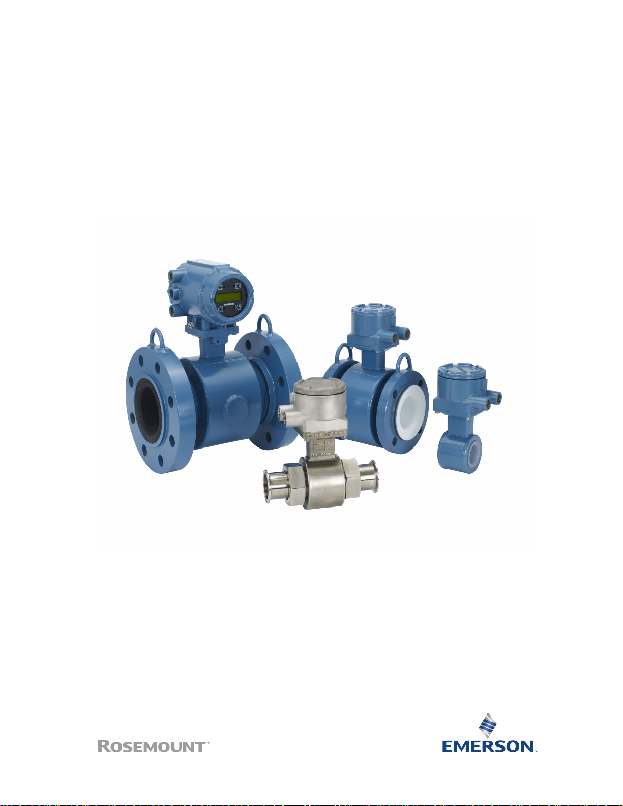
Quick Install Guide
00825-0100-4727, Rev DC
November 2017
Rosemount® 8700 Magnetic Flowmeter
Sensor
Page 2

1 Handling and Lifting Safety
CAUTION!
To reduce the risk of personal injury or damage to equipment, follow all
lifting and handling instructions.
• Handle all parts carefully to prevent damage. Whenever possible,
transport the system to the installation site in the original shipping
container.
• PTFE-lined sensors are shipped with end covers that protect it from both
mechanical damage and normal unrestrained distortion. Remove the end
covers just before installation.
• Keep the shipping plugs in the conduit ports until you are ready to
connect and seal them. Appropriate care should be taken to prevent
water ingress.
• The sensor should be supported by the pipeline. Pipe supports are
recommended on both the inlet and outlet sides of the sensor pipeline.
There should be no additional support attached to the sensor.
• Use proper PPE (Personal Protection Equipment) including safety glasses
and steel toed shoes.
• Do not lift the meter by holding the electronics housing or junction box.
• The sensor liner is vulnerable to handling damage. Never place anything
through the sensor for the purpose of lifting or gaining leverage. Liner
damage can render the sensor useless.
• Do not drop the device from any height.
Quick Install Guide
November 2017
2 Rosemount 8700 Magnetic Flowmeter Sensor
Page 3
1.1 Lifting lugs
CAUTION!
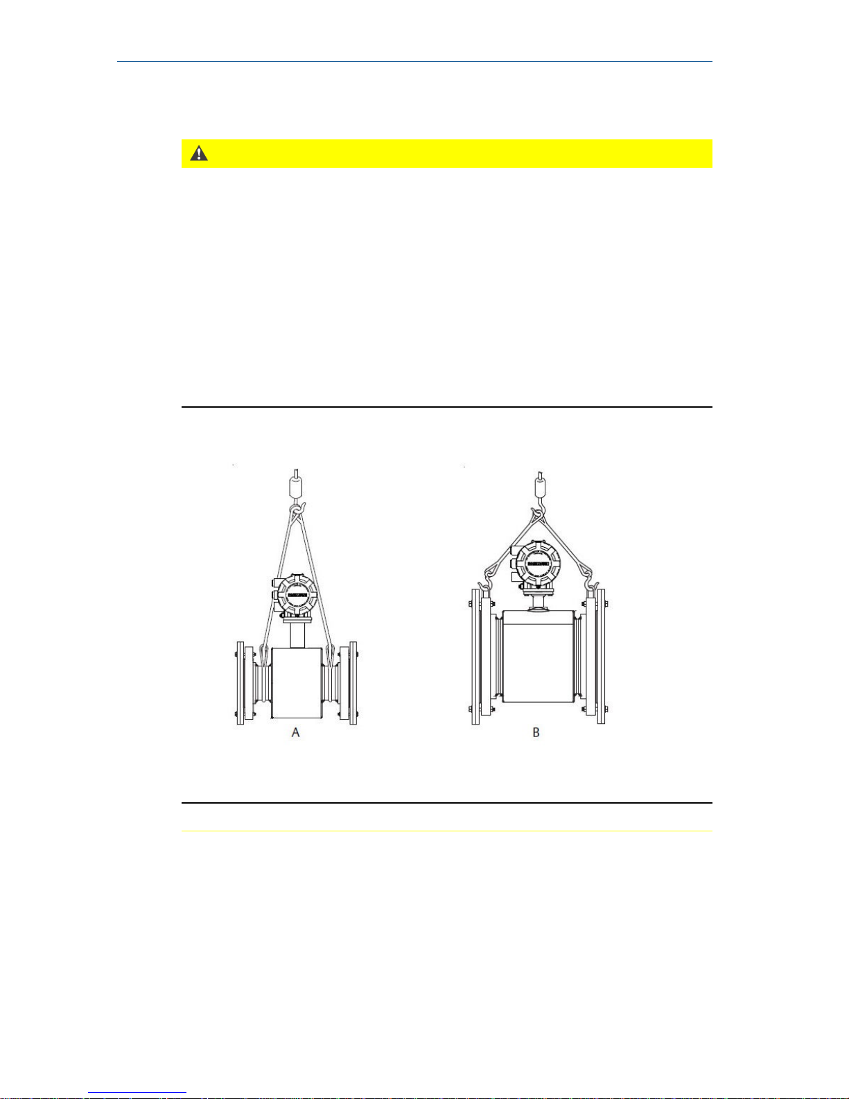
If provided, use the lifting lugs on each flange to handle the Magnetic
Flowmeter when it is transported and lowered into place at the installation
site. If lifting lugs are not provided, the Magnetic Flowmeter must be
supported with a lifting sling on each side of the housing.
• Standard pressure 3-in. through 36-in. flanged magnetic flowmeters
come with lifting lugs.
• High pressure (above 600#) 1-in. through 24-in. flanged magnetic
flowmeters come with lifting lugs.
• Wafers and sanitary magnetic flowmeters do not come with lifting lugs.
Example lifting without and with lifting lugsFigure 1-1:
A. Without lifting lugs
B. With lifting lugs
November 2017
Quick Install Guide
Quick Install Guide 3
Page 4
2 Introduction
This document provides basic installation guidelines for the Rosemount 8700
Magnetic Flowmeter sensor.
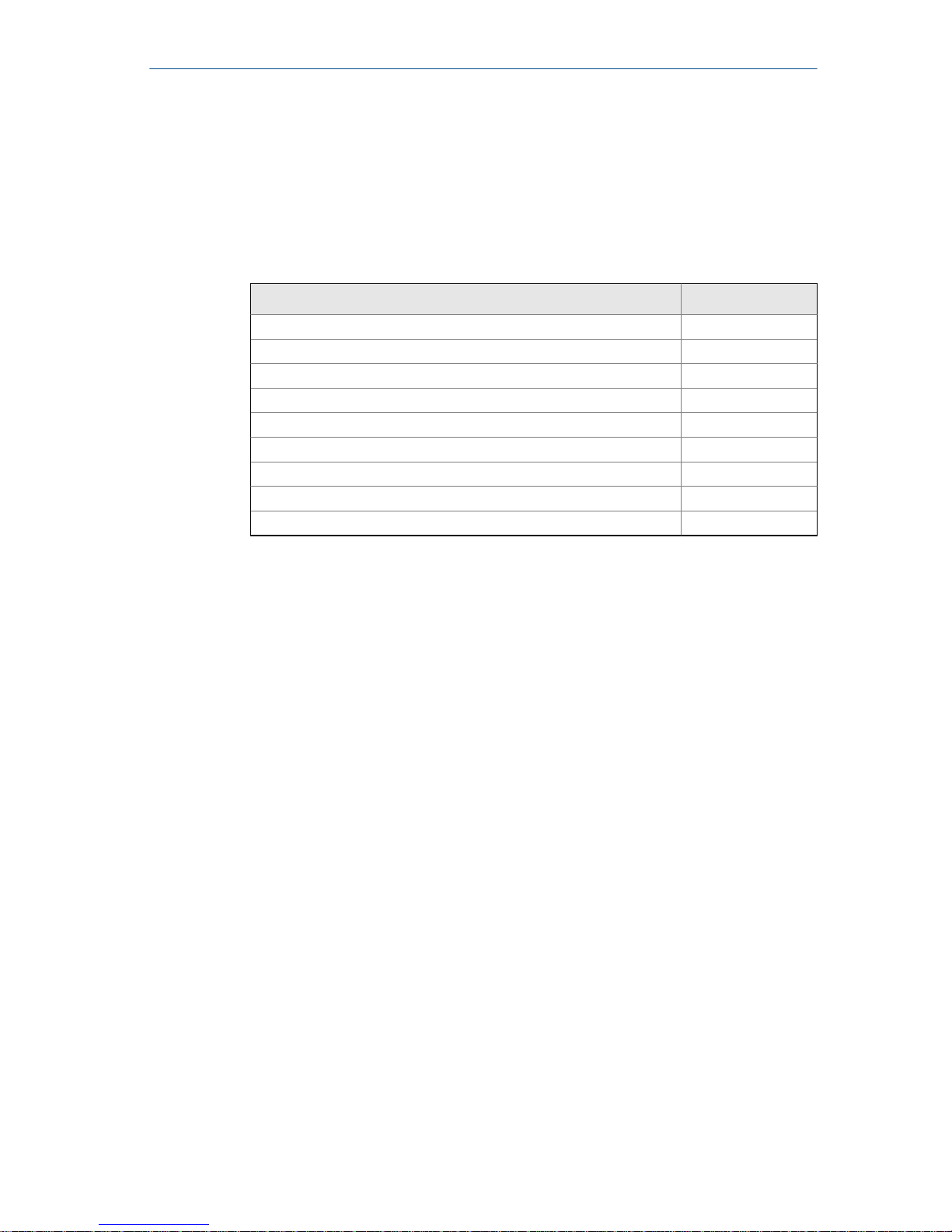
• For transmitter installation instructions, refer to the appropriate
Rosemount quick installation guide:
Product name Document number
8732EM Transmitter with HART® Protocol 00825-0100-4444
8732EM Transmitter with Modbus® RS-485 Protocol 00825-0400-4444
8712EM Transmitter with HART® Protocol 00825-0100-4445
8712EM Transmitter with Modbus® RS-485 Protocol 00825-0400-4445
8732E Magnetic Flowmeter System 00825-0100-4662
8732E Magnetic Flowmeter System with FOUNDATION™ fieldbus 00825-0100-4663
8732E Magnetic Flowmeter System with PROFIBUS PA digital fieldbus 00825-0100-4665
8712E Magnetic Flowmeter System 00825-0100-4664
8712H Magnetic Flowmeter Systems 00825-0100-4729
• For additional installation information, configuration, maintenance, and
troubleshooting, refer to the appropriate reference manual.
All user documentation can be found at www.emerson.com. For more contact
information see Section 2.2.
2.1
Return policy
Emerson procedures must be followed when returning equipment. These
procedures ensure legal compliance with government transportation
agencies and help provide a safe working environment for Emerson
employees. Failure to follow Emerson procedures will result in your
equipment being refused delivery.
Quick Install Guide
November 2017
4 Rosemount 8700 Magnetic Flowmeter Sensor
Page 5
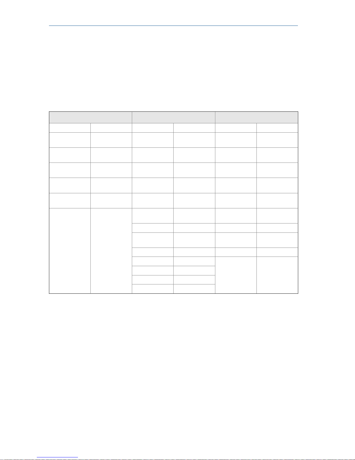
2.2 Emerson Flow customer service
Email:
• Worldwide: [email protected]
• Asia-Pacific: [email protected]
Telephone:
North and South America Europe and Middle East Asia Pacific
United States 800 522 6277 U.K. 0870 240 1978 Australia 800 158 727
Canada +1 303 527
5200
The Netherlands
+31 (0) 704 136
666
New Zealand 099 128 804
Mexico +41 (0) 41 7686
111
France 0800 917 901 India 800 440 1468
Argentina +54 11 4837
7000
Germany 0800 182 5347 Pakistan 888 550 2682
Brazil +55 15 3413
8000
Italy 8008 77334 China +86 21 2892
9000
Venezuela +58 26 1731
3446
Central & Eastern
+41 (0) 41 7686
111
Japan +81 3 5769
6803
Russia/CIS +7 495 981
9811
South Korea +82 2 3438
4600
Egypt 0800 000 0015 Singapore +65 6 777 8211
Oman 800 70101 Thailand 001 800 441
6426
Qatar 431 0044 Malaysia 800 814 008
Kuwait 663 299 01
South Africa 800 991 390
Saudi Arabia 800 844 9564
UAE 800 0444 0684
November 2017 Quick Install Guide
Quick Install Guide 5
Page 6
3 Location and Position
3.1 Environmental considerations
To ensure maximum transmitter life, avoid extreme temperatures and
excessive vibration. Typical problem areas include the following:
• Tropical/desert installations in direct sunlight
• Outdoor installations in arctic climates
Remote mounted transmitters may be installed in the control room to
protect the electronics from the harsh environment and to provide easy
access for configuration or service.
3.2
Upstream and downstream piping
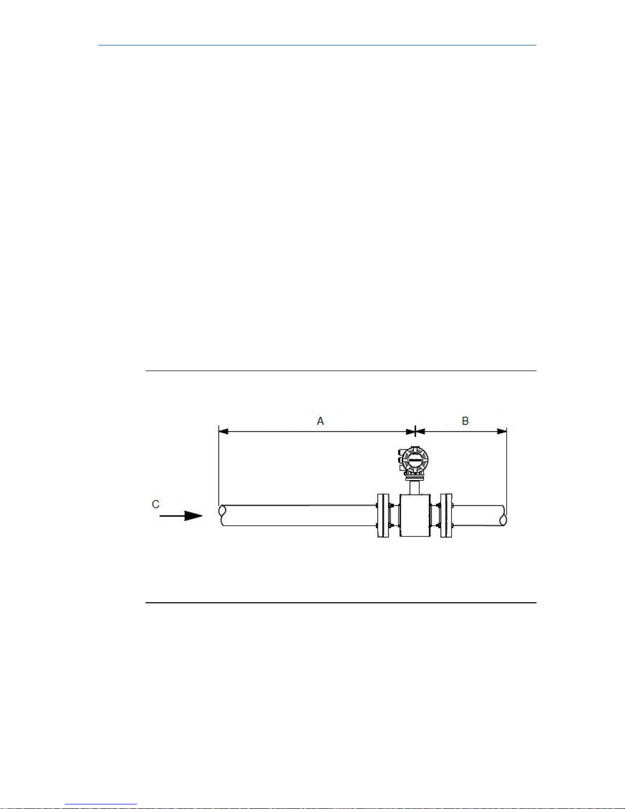
To ensure specified accuracy over widely varying process conditions, install
the sensor with a minimum of five straight pipe diameters upstream and two
pipe diameters downstream from the electrode plane.
Upstream and downstream straight pipe diametersFigure 3-1:
A. Five pipe diameters (upstream)
B. Two pipe diameters (downstream)
C. Flow direction
Installations with reduced upstream and downstream straight runs are
possible. In reduced straight run installations, the meter may not meet
absolute accuracy specifications. Reported flow rates will still be highly
repeatable.
3.3
Flow direction
The sensor should be mounted so that the arrow points in the direction of
flow.
Quick Install Guide
November 2017
6 Rosemount 8700 Magnetic Flowmeter Sensor
Page 7
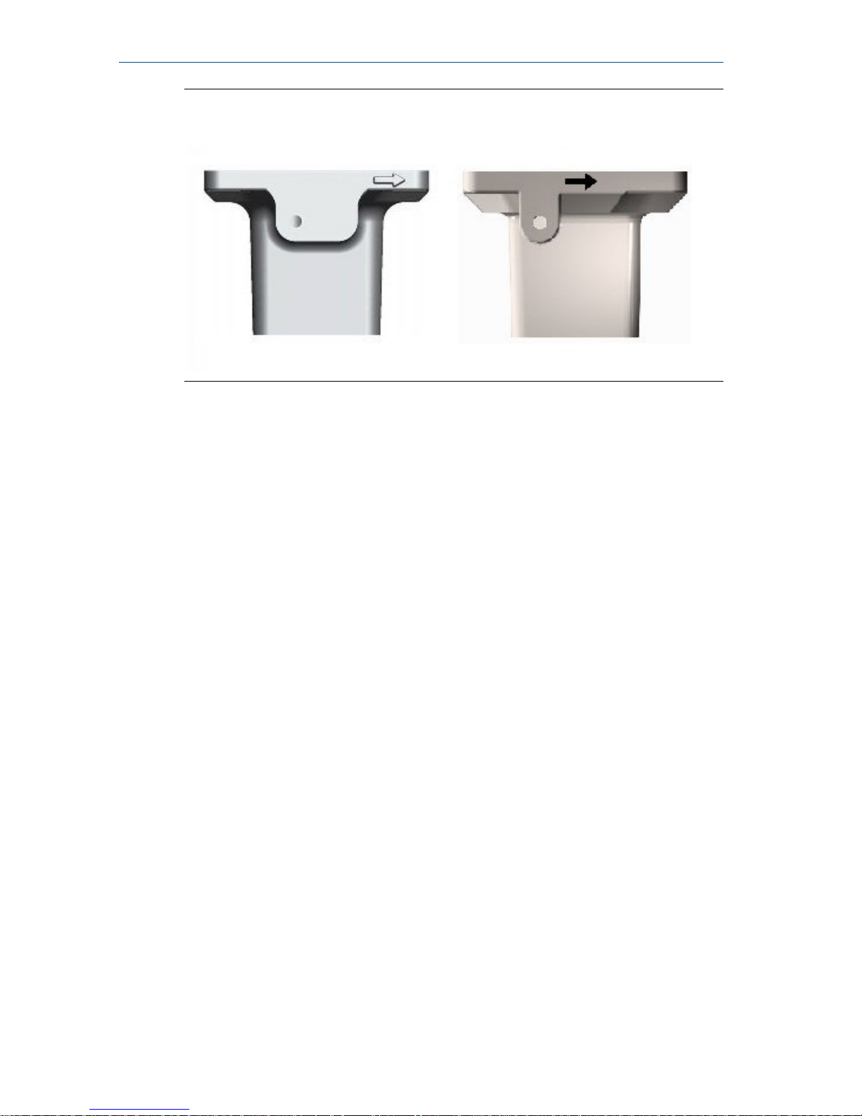
Flow direction arrowFigure 3-2:
November 2017 Quick Install Guide
Quick Install Guide 7
Page 8
3.4 Sensor piping location and orientation
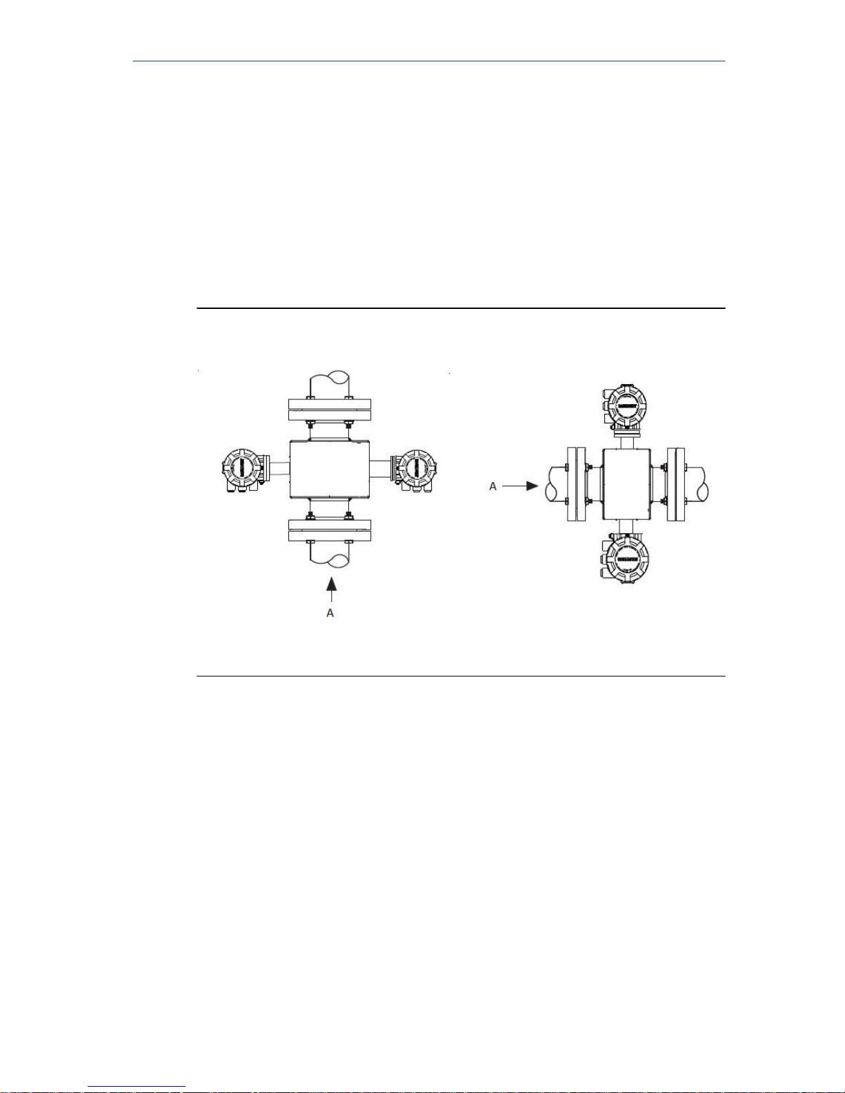
The sensor should be installed in a location that ensures it remains full during
operation. Depending on where it is installed, orientation must also be
considered.
• Vertical installation with upward process fluid flow keeps the cross-
sectional area full, regardless of flow rate.
• Horizontal installation should be restricted to low piping sections that are
normally full.
Sensor orientationFigure 3-3:
A. Flow direction
Quick Install Guide
November 2017
8 Rosemount 8700 Magnetic Flowmeter Sensor
Page 9
3.5 Electrode orientation
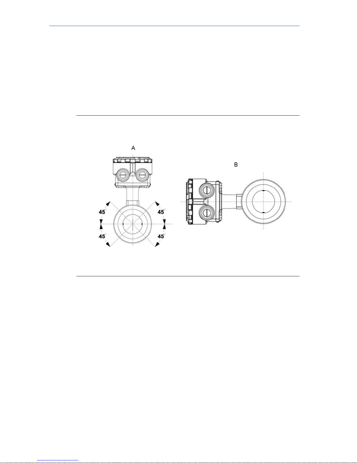
The electrodes in the sensor are properly oriented when the two
measurement electrodes are in the 3 and 9 o’clock positions or within 45
degrees from the horizontal, as shown on the left side of Figure 3-4. Avoid any
mounting orientation that positions the top of the sensor at 90 degrees from
the vertical position as shown on the right of the Electrode Orientation
figure.
Electrode orientationFigure 3-4:
A. Correct orientation
B. Incorrect orientation
The sensor may require a specific orientation to comply with Hazardous Area
T-code rating. Refer to the approrpirate reference manual for any potential
restrictions.
November 2017
Quick Install Guide
Quick Install Guide 9
Page 10
4 Sensor Installation
4.1 Flanged sensors
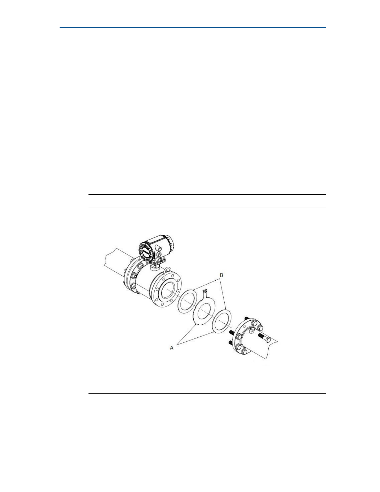
Gaskets
The sensor requires a gasket at each process connection. The gasket material
must be compatible with the process fluid and operating conditions. Gaskets
are required on each side of a grounding ring (see Figure 4-1). All other
applications (including sensors with lining protectors or a grounding
electrode) require only one gasket on each process connection.
Note
Metallic or spiral-wound gaskets should not be used as they will damage the
liner face of the sensor. If spiral wound or metallic gaskets are required for
the application, lining protectors must be used.
Gasket placement for flanged sensorsFigure 4-1:
A. Grounding ring and gasket (optional)
B. Customer-supplied gasket
Bolts
Note
Do not bolt one side at a time. Tighten both sides simultaneously. Example:
1. Snug upstream
Quick Install Guide
November 2017
10 Rosemount 8700 Magnetic Flowmeter Sensor
Page 11
2. Snug downstream
3. Tighten upstream
4. Tighten downstream
Do not snug and tighten the upstream side and then snug and tighten the
downstream side. Failure to alternate between the upstream and
downstream flanges when tightening bolts may result in liner damage.
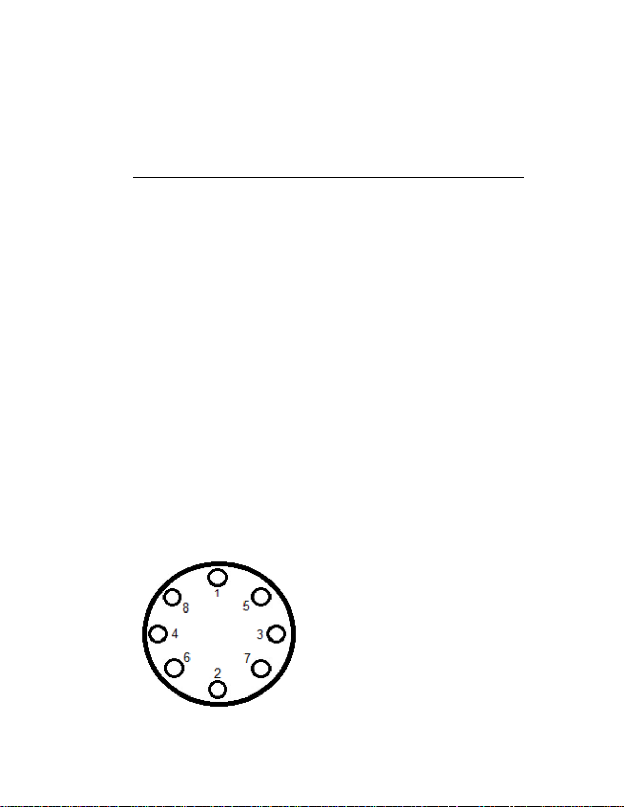
Suggested torque values by sensor line size and liner type are listed in
Table 4-2 for ASME B16.5 flanges and Table 4-3 or Table 4-4 for EN flanges.
Consult the factory if the flange rating of the sensor is not listed. Tighten
flange bolts on the upstream side of the sensor in the incremental sequence
shown in Figure 4-2 to 20% of the suggested torque values. Repeat the
process on the downstream side of the sensor. For sensors with greater or
fewer flange bolts, tighten the bolts in a similar crosswise sequence. Repeat
this entire tightening sequence at 40%, 60%, 80%, and 100% of the suggested
torque values.
If leakage occurs at the suggested torque values, the bolts can be tightened
in additional 10% increments until the joint stops leaking, or until the
measured torque value reaches the maximum torque value of the bolts.
Practical consideration for the integrity of the liner often leads to distinct
torque values to stop leakage due to the unique combinations of flanges,
bolts, gaskets, and sensor liner material.
Check for leaks at the flanges after tightening the bolts. Failure to use the
correct tightening methods can result in severe damage. While under
pressure, sensor materials may deform over time and require a second
tightening 24 hours after the initial installation.
Flange bolt torquing sequenceFigure 4-2:
November 2017 Quick Install Guide
Quick Install Guide 11
Page 12
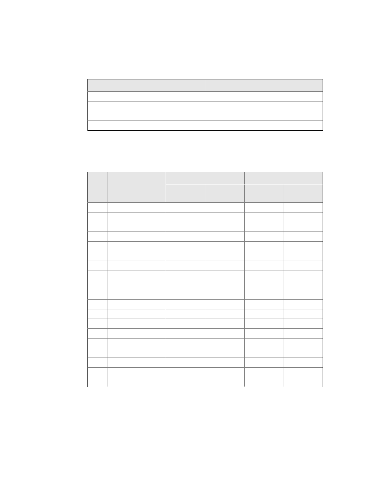
Prior to installation, identify the lining material of the flow sensor to ensure
the suggested torque values are applied.
Lining materialTable 4-1:
Fluoropolymer liners Other liners
T - PTFE P - Polyurethane
F - ETFE N - Neoprene
A - PFA L - Linatex (Natural Rubber)
K - PFA+ D - Adiprene
Suggested flange bolt torque values for Rosemount 8705
(ASME)
Table 4-2:
Size
Code Line Size
Fluoropolymer liners Other liners
Class 150
(pound-feet)
Class 300
(pound-feet)
Class 150
(pound-feet)
Class 300
(pound feet)
005 0.5-in. (15 mm) 8 8 N/A N /A
010 1-in. (25 mm) 8 12 6 10
015 1.5-in. (40 mm) 13 25 7 18
020 2-in. (50 mm) 19 17 14 11
025 2.5-in. (65 mm) 22 24 17 16
030 3-in. (80 mm) 34 35 23 23
040 4-in. (100 mm) 26 50 17 32
050 5-in. (125 mm) 36 60 25 35
060 6-in. (150 mm) 45 50 30 37
080 8-in. (200 mm) 60 82 42 55
100 10-in. (250 mm) 55 80 40 70
120 12-in. (300 mm) 65 125 55 105
140 14-in. (350 mm) 85 110 70 95
160 16-in. (400 mm) 85 160 65 140
180 18-in. (450 mm) 120 170 95 150
200 20-in. (500 mm) 110 175 90 150
240 24-in. (600 mm) 165 280 140 250
300 30-in. (750 mm) 195 415 165 375
360 36-in. (900 mm) 280 575 245 525
Quick Install Guide November 2017
12 Rosemount 8700 Magnetic Flowmeter Sensor
Page 13
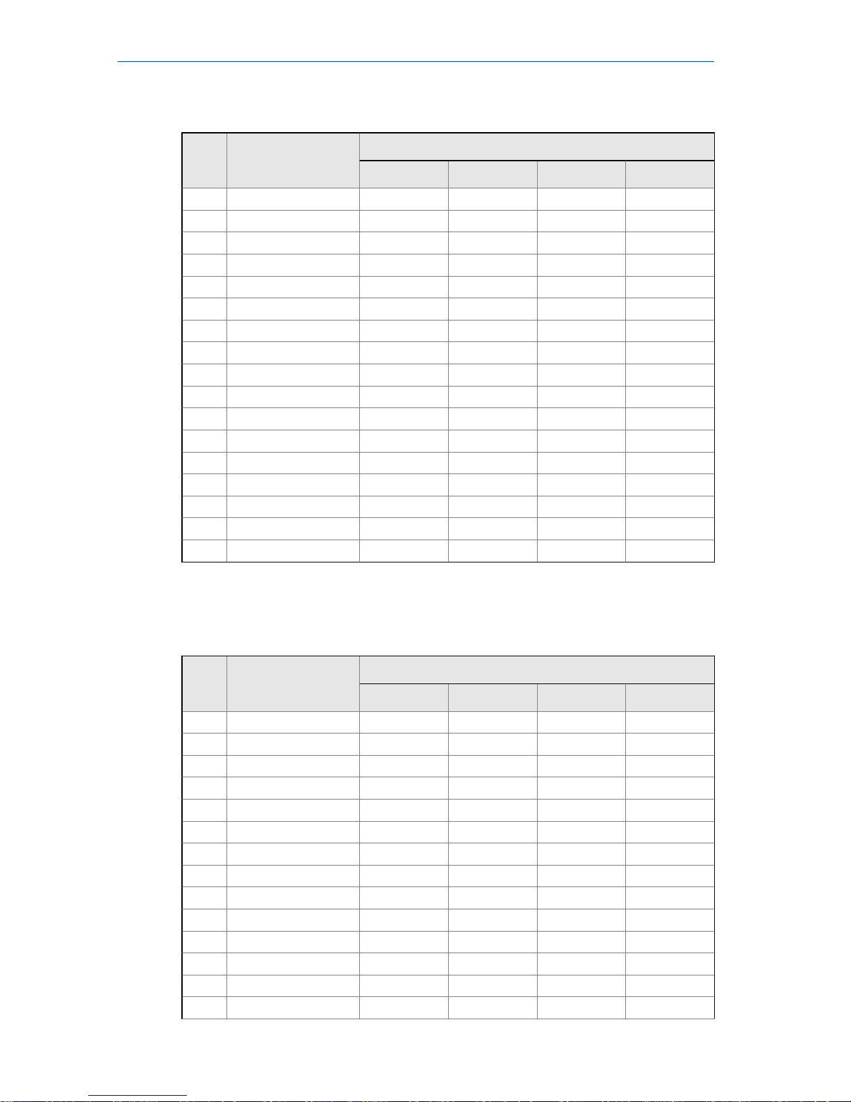
Suggested flange bolt torque values for Rosemount 8705
sensors with fluoropolymer liners (EN 1092-1)
Table 4-3:
Size
code Line size
Fluoropolymer liners (in Newton-meters)
PN 10 PN 16 PN 25 PN 40
005 0.5-in. (15 mm) N/A N/A N/A 10
010 1-in. (25 mm) N/A N/A N/A 20
015 1.5-in. (40 mm) N/A N/A N/A 50
020 2-in. (50 mm) N/A N/A N/A 60
025 2.5-in. (65 mm) N/A N/A N/A 50
030 3-in. (80 mm) N/A N/A N/A 50
040 4-in. (100 mm) N/A 50 N/A 70
050 5.0-in. (125 mm) N/A 70 N/A 100
060 6-in. (150mm) N/A 90 N/A 130
080 8-in. (200 mm) 130 90 130 170
100 10-in. (250 mm) 100 130 190 250
120 12-in. (300 mm) 120 170 190 270
140 14-in. (350 mm) 160 220 320 410
160 16-in. (400 mm) 220 280 410 610
180 18-in. (450 mm) 190 340 330 420
200 20-in. (500 mm) 230 380 440 520
240 24-in. (600 mm) 290 570 590 850
Suggested flange bolt torque values for Rosemount 8705
sensors with non-fluoropolymer liners (EN 1092-1)
Table 4-4:
Size
Code Line Size
Non-fluoropolymer liners (in Newton-meters)
PN 10 PN 16 PN 25 PN 40
005 0.5-in. (15 mm) N/A N/A N/A 20
010 1-in. (25 mm) N/A N/A N/A 30
015 1.5-in. (40 mm) N/A N/A N/A 40
020 2-in. (50 mm) N/A N/A N/A 30
025 2.5-in. (65 mm) N/A N/A N/A 35
030 3-in. (80 mm) N/A N/A N/A 30
040 4-in. (100 mm) N/A 40 N/A 50
050 5.0-in. (125 mm) N/A 50 N/A 70
060 6-in. (150mm) N/A 60 N/A 90
080 8-in. (200 mm) 90 60 90 110
100 10-in. (250 mm) 70 80 130 170
120 12-in. (300 mm) 80 110 130 180
140 14-in. (350 mm) 110 150 210 288
160 16-in. (400 mm) 150 190 280 410
November 2017 Quick Install Guide
Quick Install Guide 13
Page 14
Suggested flange bolt torque values for Rosemount 8705
sensors with non-fluoropolymer liners (EN 1092-1) (continued)
Table 4-4:
Size
Code Line Size
Non-fluoropolymer liners (in Newton-meters)
PN 10 PN 16 PN 25 PN 40
180 18-in. (450 mm) 130 230 220 280
200 20-in. (500 mm) 150 260 300 350
240 24-in. (600 mm) 200 380 390 560
4.2 Wafer sensors
When installing wafer sensors, there are several components that must be
included and requirements that must be met.
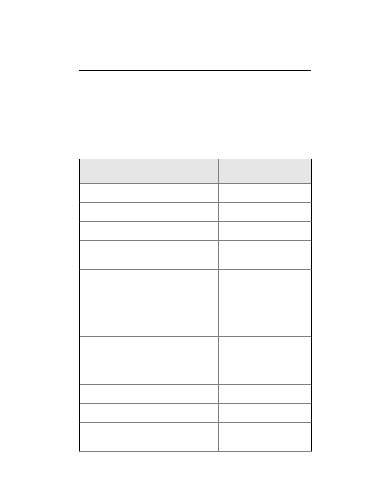
Wafer sensors installation components and assembly
requirements
Figure 4-3:
A. Ground ring (optional)
B. Customer supplied gaskets
C. Spacer installation (horizontal meters)
D. Spacer installation (vertical meters)
E. O-ring
F. Installation studs, nuts, and washers (optional)
G. Wafer alignment spacer
H. Flow
Gaskets
The sensor requires a gasket at each process connection. The gasket material
selected must be compatible with the process fluid and operating conditions.
Gaskets are required on each side of a grounding ring. See Figure 4-3.
Quick Install Guide
November 2017
14 Rosemount 8700 Magnetic Flowmeter Sensor
Page 15
Note
Metallic or spiral-wound gaskets should not be used as they will damage the
liner face of the sensor.
Alignment spacers
On 1.5 inch through 8 inch (40 through 200 mm) line sizes, Rosemount
requires installing the alignment spacers to ensure proper centering of the
wafer sensor between the process flanges. To order an Alignment Spacer Kit
(quantity 3 spacers) use p/n 08711-3211-xxxx where xxxx equals the dash
number shown in Table 4-5.
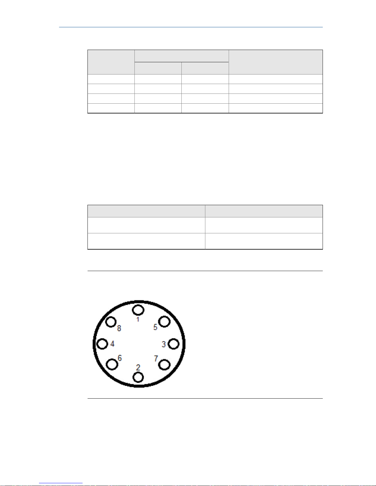
Rosemount alignment spacersTable 4-5:
Dash-no. (xxxx)
Line size
Flange rating(in) (mm)
0A15 1.5 40 JIS 10K-20K
0A20 2 50 JIS 10K-20K
0A30 3 80 JIS 10K
0B15 1.5 40 JIS 40K
AA15 1.5 40 ASME- 150#
AA20 2 50 ASME - 150#
AA30 3 80 ASME - 150#
AA40 4 100 ASME - 150#
AA60 6 150 ASME - 150#
AA80 8 200 ASME - 150#
AB15 1.5 40 ASME - 300#
AB20 2 50 ASME - 300#
AB30 3 80 ASME - 300#
AB40 4 100 ASME - 300#
AB60 6 150 ASME - 300#
AB80 8 200 ASME - 300#
DB40 4 100 EN 1092-1 - PN10/16
DB60 6 150 EN 1092-1 - PN10/16
DB80 8 200 EN 1092-1 - PN10/16
DC80 8 200 EN 1092-1 - PN25
DD15 1.5 40 EN 1092-1 - PN10/16/25/40
DD20 2 50 EN 1092-1 - PN10/16/25/40
DD30 3 80 EN 1092-1 - PN10/16/25/40
DD40 4 100 EN 1092-1 - PN25/40
DD60 6 150 EN 1092-1 - PN25/40
DD80 8 200 EN 1092-1 - PN40
RA80 8 200 AS40871-PN16
RC20 2 50 AS40871-PN21/35
November 2017 Quick Install Guide
Quick Install Guide 15
Page 16
Rosemount alignment spacers (continued)Table 4-5:
Dash-no. (xxxx)
Line size
Flange rating(in) (mm)
RC30 3 80 AS40871-PN21/35
RC40 4 100 AS40871-PN21/35
RC60 6 150 AS40871-PN21/35
RC80 8 200 AS40871-PN21/35
Studs
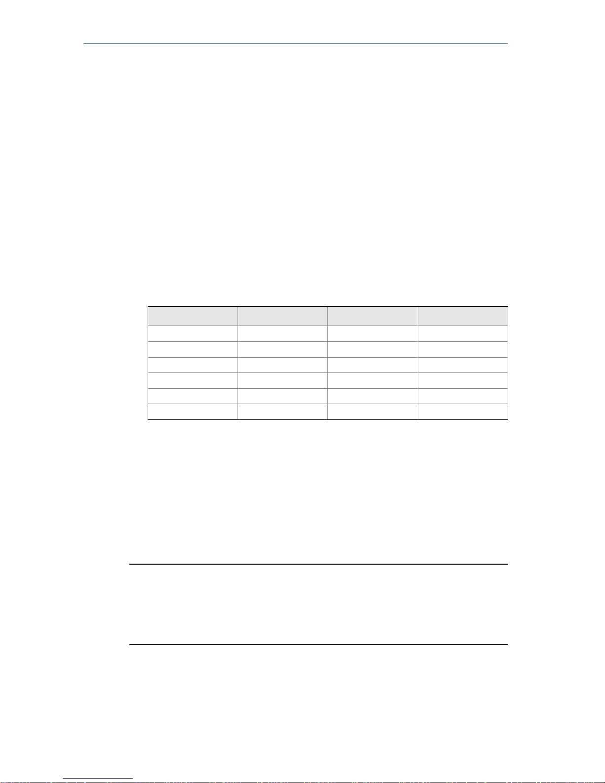
Wafer sensors require threaded studs. See Figure 4-4 for torque sequence.
Always check for leaks at the flanges after tightening the flange bolts. All
sensors require a second tightening 24 hours after initial flange bolt
tightening.
Stud specificationsTable 4-6:
Nominal sensor size Stud specifications
0.15–1-in. (4–25 mm) 316 SST ASTM A193, Grade B8M, Class 1 threaded mounted studs
1½–8-in. (40–200 mm) CS, ASTM A193, Grade B7, threaded mounting
studs
Flange bolt torquing sequenceFigure 4-4:
Quick Install Guide November 2017
16 Rosemount 8700 Magnetic Flowmeter Sensor
Page 17
4.2.1 Installation
1. Insert studs for the the bottom side of the sensor between the pipe
flanges and center the alignment spacer in the middle of the stud. See
Figure 4-3 for the bolt hole locations recommended for the spacers
provided. Stud specifications are listed in Table 4-6.
2. Place the sensor between the flanges. Make sure the alignment spacers
are properly centered on the studs. For vertical flow installations slide the
o-ring over the stud to keep the spacer in place. See Figure 4-3. Ensure the
spacers match the flange size and class rating for the process flanges. See
Table 4-5.
3. Insert the remaining studs, washers, and nuts.
4. Tighten to the torque specifications shown in Table 4-7. Do not overtighten the bolts or the liner may be damaged.
Rosemount 8711 torque specificationsTable 4-7:
Size code Line size Pound-feet Newton-meter
015 1.5-in. (40 mm) 15 20
020 2-in. (50 mm) 25 34
030 3-in. (80 mm) 40 54
040 4-in. (100 mm) 30 41
060 6-in. (150 mm) 50 68
080 8-in. (200 mm) 70 95
4.3 Sanitary senors
Gaskets
The sensor requires a gasket at each of its connections to adjacent devices or
piping. The gasket material selected must be compatible with the process
fluid and operating conditions.
Note
Gaskets are supplied between the IDF fitting and the process connection
fitting, such as a Tri-Clamp fitting, on all Rosemount 8721 Sanitary sensors
except when the process connection fittings are not supplied and the only
connection type is an IDF fitting.
Alignment and bolting
Standard plant practices should be followed when installing a magmeter with
sanitary fittings. Unique torque values and bolting techniques are not
required.
November 2017
Quick Install Guide
Quick Install Guide 17
Page 18
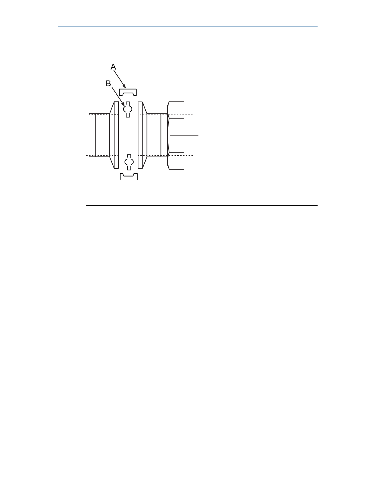
Sanitary sensor gasket and clamp alignmentFigure 4-5:
A. User supplied clamp
B. User supplied gasket
Quick Install Guide
November 2017
18 Rosemount 8700 Magnetic Flowmeter Sensor
Page 19
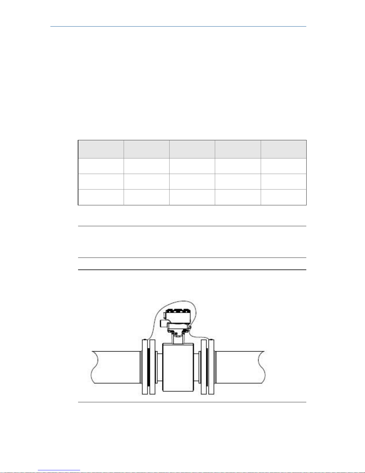
5 Process reference connection
The figures shown in this chapter illustrate process reference connections
only. Earth safety ground is also required as part of this installation, but is not
shown in the figures. Follow national, local, and plant electrical codes for
safety ground.
Use the Process reference options table to determine which process
reference option to follow for proper installation.
Process reference optionsTable 5-1:
Type of pipe
Grounding
straps Grounding rings
Reference electrode
Lining protectors
Conductive unlined pipe
See Figure 5-1 See Figure 5-2 See Figure 5-4 See Figure 5-2
Conductive lined
pipe
Insufficient
grounding
See Figure 5-2 See Figure 5-1 See Figure 5-2
Non-conductive
pipe
Insufficient
grounding
See Figure 5-3 Not recommen-
ded
See Figure 5-3
Note
For line sizes 10-inch and larger the ground strap may come attached to the
sensor body near the flange. See Figure 5-5.
Grounding straps in conductive unlined pipe or reference
electrode in lined pipe
Figure 5-1:
November 2017 Quick Install Guide
Quick Install Guide 19
Page 20
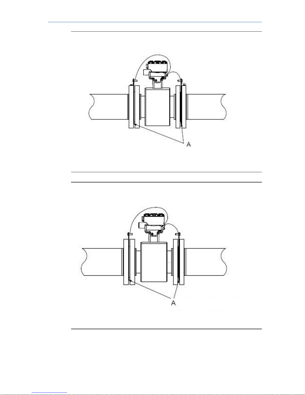
Grounding with grounding rings or lining protectors in
conductive pipe
Figure 5-2:
A. Grounding rings or lining protectors
Grounding with grounding rings or lining protectors in nonconductive pipe
Figure 5-3:
A. Grounding rings or lining protectors
Quick Install Guide
November 2017
20 Rosemount 8700 Magnetic Flowmeter Sensor
Page 21
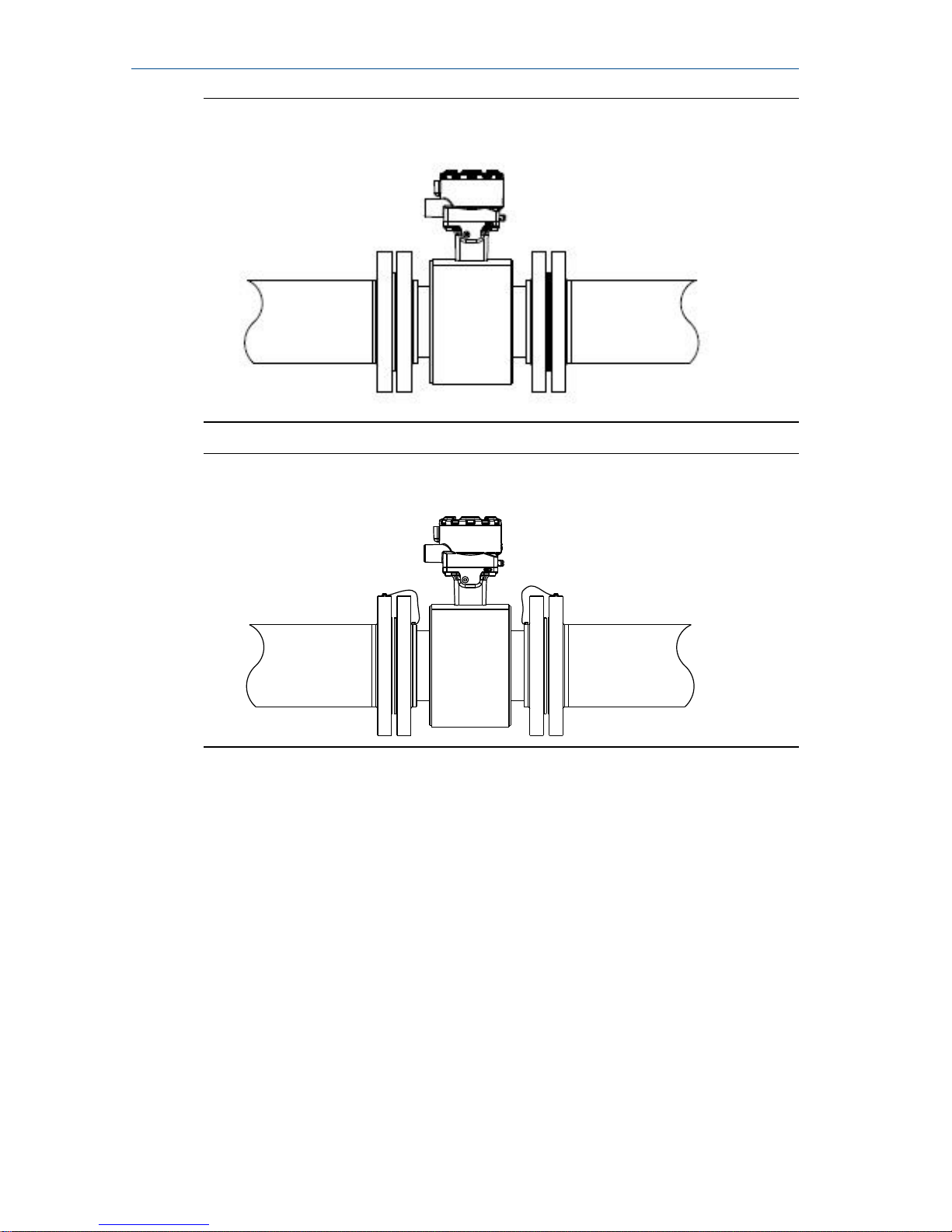
Grounding with reference electrode in conductive unlined
pipe
Figure 5-4:
Grounding for line sizes 10-in. and largerFigure 5-5:
November 2017 Quick Install Guide
Quick Install Guide 21
Page 22
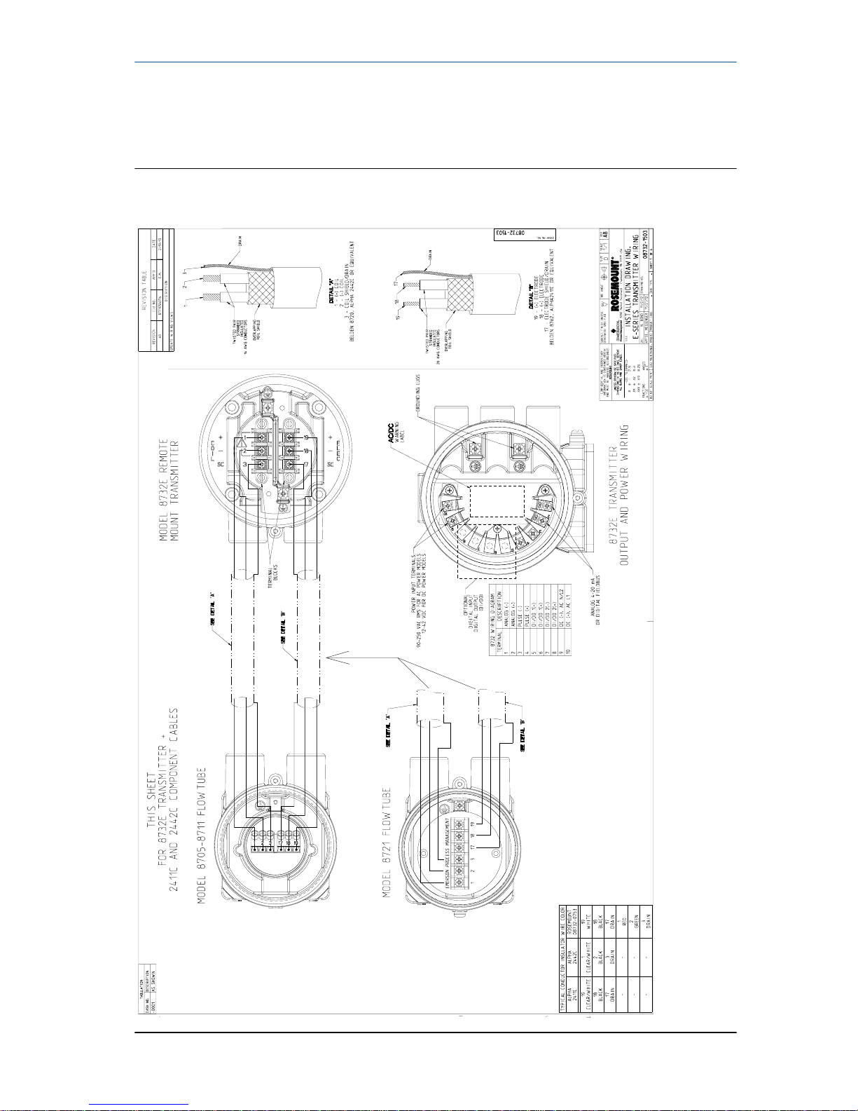
6 Wiring sensor to transmitter
Wiring 8732ES using component cableFigure 6-1:
Quick Install Guide November 2017
22 Rosemount 8700 Magnetic Flowmeter Sensor
Page 23
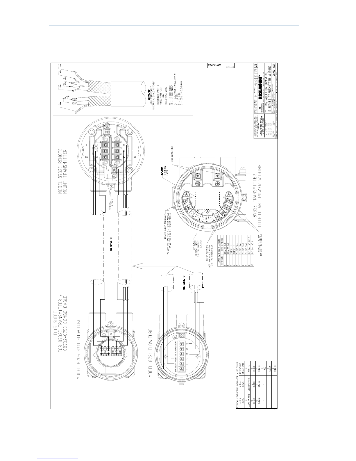
Wiring 8732ES using combination cableFigure 6-2:
November 2017 Quick Install Guide
Quick Install Guide 23
Page 24
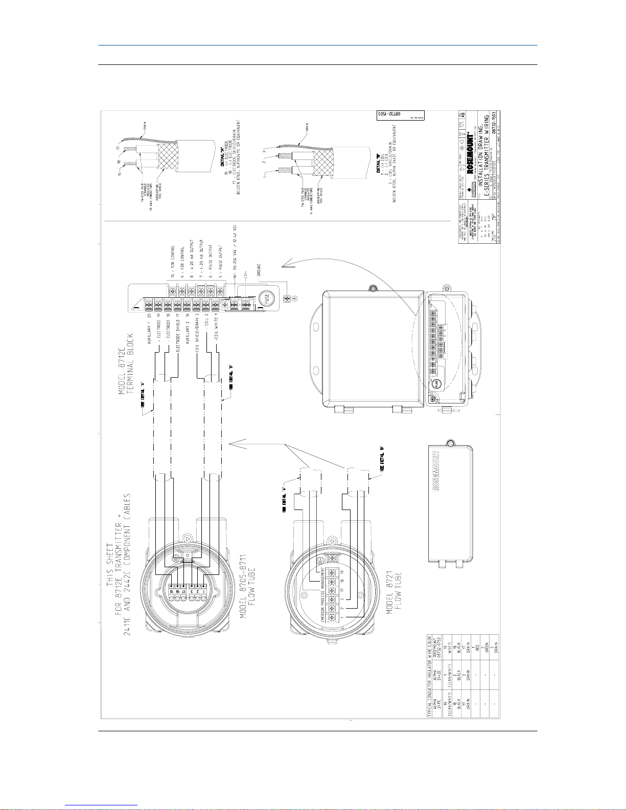
Wiring 8712ES using component cableFigure 6-3:
Quick Install Guide November 2017
24 Rosemount 8700 Magnetic Flowmeter Sensor
Page 25
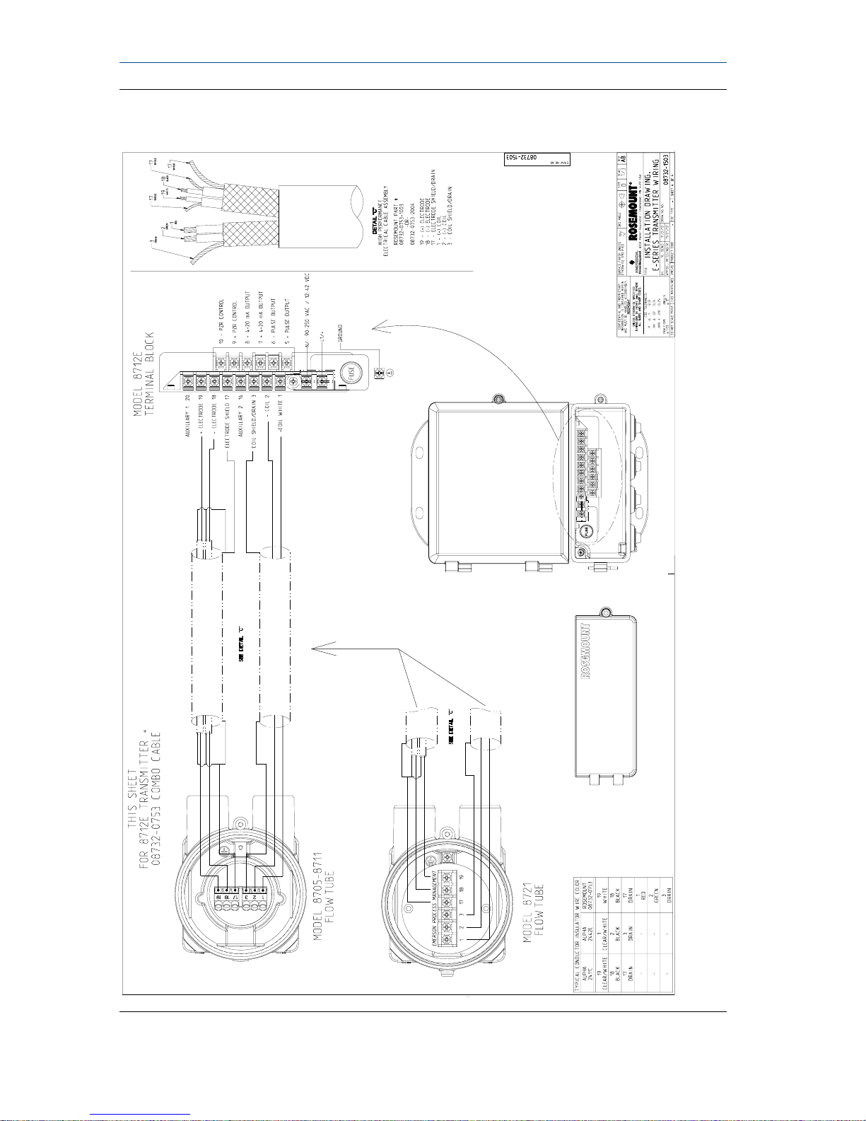
Wiring 8712ES using combination cableFigure 6-4:
November 2017 Quick Install Guide
Quick Install Guide 25
Page 26
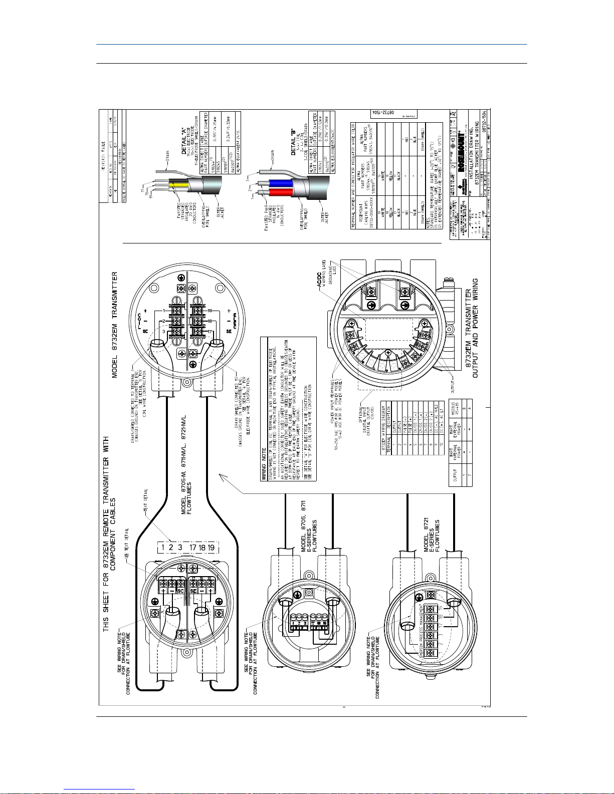
Wiring 8732EM using component cableFigure 6-5:
Quick Install Guide November 2017
26 Rosemount 8700 Magnetic Flowmeter Sensor
Page 27

Wiring 8732EM using combination cableFigure 6-6:
November 2017 Quick Install Guide
Quick Install Guide 27
Page 28

*00825-0100-4727*
Quick Install Guide
00825-0100-4727, rev. DC
November 2017
Emerson Automation Solutions USA
7070 Winchester Circle
Boulder, Colorado USA 80301
T +1 303-527-5200
T +1 800-522-6277
F +1 303-530-8459
www.emerson.com
Emerson Automation Solutions Europe
Neonstraat 1
6718 WX Ede
The Netherlands
T +31 (0) 70 413 6666
F +31 (0) 318 495 556
www.micromotion.nl
Emerson Automation Solutions Asia
1 Pandan Crescent
Singapore 128461
Republic of Singapore
T +65 6777-8211
F +65 6770-8003
Emerson Automation Solutions United Kingdom
Emerson Process Management Limited
Horsfield Way
Bredbury Industrial Estate
Stockport SK6 2SU U.K.
T +44 0870 240 1978
F +44 0800 966 181
Emerson Automation Solutions Japan
1-2-5, Higashi Shinagawa
Shinagawa-ku
Tokyo 140-0002 Japan
T +81 3 5769-6803
F +81 3 5769-6844
©
2017 Rosemount, Inc. All rights reserved.
The Emerson logo is a trademark and service mark
of Emerson Electric Co. Rosemount, 8600, 8700,
8800 marks are marks of one of the Emerson
Automation Solutions family of companies. All
other marks are property of their respective
owners.
 Loading...