

Page 1
Reference Manual
00809-0100-4727, Rev EA
October 2010
Rosemount 8700 Series
Magnetic Flowmeter Sensors
www.rosemount.com
Page 2

Page 3
Reference Manual
NOTICE
00809-0100-4727, Rev EA
October 2010
Rosemount 8700 Series
Magnetic Flowmeter Sensors
Read this manual before working with the product. For personal and system safety, and for
optimum product performance, make sure you thoroughly understand the contents before
installing, using, or maintaining this product.
Within the United States, Rosemount Inc. has two toll-free assistance numbers.
Customer Central: 1-800-999-9307(7:00 a.m. to 7:00 p.m. CST)
Technical support, quoting, and order-related questions.
North American1-800-654-7768 (24 hours a day – Includes Canada)
Response Center: Equipment service needs.
For equipment service or support needs outside the United States, your local Emerson
Process Management representative.
The products described in this document are NOT designed for
nuclear-qualified applications.
Using non-nuclear qualified products in applications that require
nuclear-qualified hardware or products may cause inaccurate readings.
For information on Rosemount nuclear-qualified products, contact your local Emerson
Process Management Sales Representative.
www.rosemount.com
Page 4

Page 5

Reference Manual
00809-0100-4727, Rev EA
October 2010
Rosemount 8700 Series
Table of Contents
SECTION 1
Introduction
SECTION 2
Installation
Manual Description . . . . . . . . . . . . . . . . . . . . . . . . . . . . . . . . . . . . . . . 1-1
Safety Information . . . . . . . . . . . . . . . . . . . . . . . . . . . . . . . . . . . . . . . . 1-2
Return of Materials . . . . . . . . . . . . . . . . . . . . . . . . . . . . . . . . . . . . . . . 1-2
Safety Messages. . . . . . . . . . . . . . . . . . . . . . . . . . . . . . . . . . . . . . . . . 2-1
Sensor Handling . . . . . . . . . . . . . . . . . . . . . . . . . . . . . . . . . . . . . . . . . 2-3
Sensor Mounting . . . . . . . . . . . . . . . . . . . . . . . . . . . . . . . . . . . . . . . . . 2-4
Upstream/Downstream Piping . . . . . . . . . . . . . . . . . . . . . . . . . . . . 2-4
Sensor Orientation . . . . . . . . . . . . . . . . . . . . . . . . . . . . . . . . . . . . . 2-4
Flow Direction. . . . . . . . . . . . . . . . . . . . . . . . . . . . . . . . . . . . . . . . . 2-6
Installation (Flanged Sensor). . . . . . . . . . . . . . . . . . . . . . . . . . . . . . . . 2-7
Gaskets . . . . . . . . . . . . . . . . . . . . . . . . . . . . . . . . . . . . . . . . . . . . . 2-7
Flange Bolts . . . . . . . . . . . . . . . . . . . . . . . . . . . . . . . . . . . . . . . . . . 2-7
Installation (Wafer Sensor) . . . . . . . . . . . . . . . . . . . . . . . . . . . . . . . . 2-10
Gaskets . . . . . . . . . . . . . . . . . . . . . . . . . . . . . . . . . . . . . . . . . . . . 2-10
Flange Bolts . . . . . . . . . . . . . . . . . . . . . . . . . . . . . . . . . . . . . . . . . 2-11
Installation (Sanitary Sensor). . . . . . . . . . . . . . . . . . . . . . . . . . . . . . . 2-12
Gaskets . . . . . . . . . . . . . . . . . . . . . . . . . . . . . . . . . . . . . . . . . . . . 2-12
Alignment and Bolting. . . . . . . . . . . . . . . . . . . . . . . . . . . . . . . . . . 2-12
Process Leak Protection (Optional). . . . . . . . . . . . . . . . . . . . . . . . . . 2-13
Standard Housing Configuration . . . . . . . . . . . . . . . . . . . . . . . . . 2-13
Relief Valves. . . . . . . . . . . . . . . . . . . . . . . . . . . . . . . . . . . . . . . . . 2-14
Process Leak Containment . . . . . . . . . . . . . . . . . . . . . . . . . . . . . 2-14
Conduit Ports and Connections . . . . . . . . . . . . . . . . . . . . . . . . . . 2-15
Conduit Cables. . . . . . . . . . . . . . . . . . . . . . . . . . . . . . . . . . . . . . . 2-16
Electrical Considerations . . . . . . . . . . . . . . . . . . . . . . . . . . . . . . . 2-17
Sensor Connections . . . . . . . . . . . . . . . . . . . . . . . . . . . . . . . . . . . . . 2-18
Rosemount Sensors. . . . . . . . . . . . . . . . . . . . . . . . . . . . . . . . . . . 2-18
Transmitter to Sensor Wiring . . . . . . . . . . . . . . . . . . . . . . . . . . . . 2-18
SECTION 3
Operation and
Maintenance
www.rosemount.com
Calibration . . . . . . . . . . . . . . . . . . . . . . . . . . . . . . . . . . . . . . . . . . . . . . 3-1
Grounding . . . . . . . . . . . . . . . . . . . . . . . . . . . . . . . . . . . . . . . . . . . . . . 3-1
Material Selection . . . . . . . . . . . . . . . . . . . . . . . . . . . . . . . . . . . . . . . . 3-3
Magnetic Flowmeter Sizing . . . . . . . . . . . . . . . . . . . . . . . . . . . . . . . . . 3-4
Page 6

Rosemount 8700 Series
Reference Manual
00809-0100-4727, Rev EA
October 2010
SECTION 4
Maintenance and
Troubleshooting
APPENDIX A
Reference Data
Safety Information . . . . . . . . . . . . . . . . . . . . . . . . . . . . . . . . . . . . . . . . 4-1
Installation Check and Guide. . . . . . . . . . . . . . . . . . . . . . . . . . . . . . . . 4-2
Diagnostic Messages. . . . . . . . . . . . . . . . . . . . . . . . . . . . . . . . . . . . . . 4-3
Transmitter Troubleshooting . . . . . . . . . . . . . . . . . . . . . . . . . . . . . . . . 4-5
Quick Troubleshooting. . . . . . . . . . . . . . . . . . . . . . . . . . . . . . . . . . . . . 4-7
Step 1: Wiring Errors . . . . . . . . . . . . . . . . . . . . . . . . . . . . . . . . . . . 4-7
Step 2: Process Noise . . . . . . . . . . . . . . . . . . . . . . . . . . . . . . . . . . 4-7
Step 3: Installed Sensor Tests . . . . . . . . . . . . . . . . . . . . . . . . . . . . 4-7
Step 4: Uninstalled Sensor Tests. . . . . . . . . . . . . . . . . . . . . . . . . . 4-9
Rosemount 8700 Series Product Specifications Overview . . . . . . . . .A-1
E-Series Performance Specifications . . . . . . . . . . . . . . . . . . . . . . . . .A-5
High Signal System Performance Specifications. . . . . . . . . . . . . . . . .A-7
Rosemount Flanged Sensor Specifications. . . . . . . . . . . . . . . . . . . . .A-9
Flanged Sensor Functional Specifications. . . . . . . . . . . . . . . . . . . . . .A-9
Flanged Sensor Physical Specifications . . . . . . . . . . . . . . . . . . . . . .A-11
Rosemount 8711 Wafer Sensor Specifications. . . . . . . . . . . . . . . . .A-13
8711 Functional Specifications . . . . . . . . . . . . . . . . . . . . . . . . . . . . .A-13
8711 Physical Specifications. . . . . . . . . . . . . . . . . . . . . . . . . . . . . . .A-14
Rosemount 8721 Sanitary Sensor Specifications . . . . . . . . . . . . . . .A-16
8721 Functional Specifications . . . . . . . . . . . . . . . . . . . . . . . . . . . . .A-16
8721 Physical Specifications. . . . . . . . . . . . . . . . . . . . . . . . . . . . . . .A-17
Dimensional Drawings. . . . . . . . . . . . . . . . . . . . . . . . . . . . . . . . . . . .A-20
Rosemount Flanged Sensors. . . . . . . . . . . . . . . . . . . . . . . . . . . .A-36
Rosemount High-Signal Magmeter System . . . . . . . . . . . . . . . . .A-36
Options (Include with selected model number) . . . . . . . . . . . . . .A-39
Rosemount 8711 Wafer Sensors . . . . . . . . . . . . . . . . . . . . . . . . .A-43
Options (Include with selected model number) . . . . . . . . . . . . . .A-45
Rosemount 8721 Hygienic Sensors . . . . . . . . . . . . . . . . . . . . . . .A-46
Options (Include with selected model number) . . . . . . . . . . . . . .A-47
Tagging. . . . . . . . . . . . . . . . . . . . . . . . . . . . . . . . . . . . . . . . . . . . .A-48
Ordering Procedure . . . . . . . . . . . . . . . . . . . . . . . . . . . . . . . . . . .A-48
Standard Configuration. . . . . . . . . . . . . . . . . . . . . . . . . . . . . . . . .A-48
Cable Requirements for Remote Transmitters. . . . . . . . . . . . . . .A-48
APPENDIX B
Approvals
TOC-2
Approved Manufacturing Locations. . . . . . . . . . . . . . . . . . . . . . . . . . .B-1
European Directive Information. . . . . . . . . . . . . . . . . . . . . . . . . . . . . .B-1
ATEX Directive. . . . . . . . . . . . . . . . . . . . . . . . . . . . . . . . . . . . . . . .B-1
European Pressure Equipment Directive (PED) (97/23/EC) . . . . .B-1
Electro Magnetic Compatibility (EMC) (2004/108/EC) . . . . . . . . . .B-2
Low Voltage Directive (2006/95/EC) . . . . . . . . . . . . . . . . . . . . . . .B-2
Other important guidelines . . . . . . . . . . . . . . . . . . . . . . . . . . . . . . .B-2
IECEx Certificates . . . . . . . . . . . . . . . . . . . . . . . . . . . . . . . . . . . . .B-2
Hazardous Locations Product Approvals Offering. . . . . . . . . . . . . . . .B-3
Hazardous Location Certifications. . . . . . . . . . . . . . . . . . . . . . . . . . . .B-7
North American Certifications. . . . . . . . . . . . . . . . . . . . . . . . . . . . .B-7
Canadian Standards Association (CSA). . . . . . . . . . . . . . . . . . . . .B-7
European Certifications . . . . . . . . . . . . . . . . . . . . . . . . . . . . . . . . .B-7
International Certifications . . . . . . . . . . . . . . . . . . . . . . . . . . . . . . .B-8
Page 7
Reference Manual
00809-0100-4727, Rev EA
October 2010
Section 1 Introduction
Manual Description . . . . . . . . . . . . . . . . . . . . . . . . . . . . . . . page 1-1
Safety Information . . . . . . . . . . . . . . . . . . . . . . . . . . . . . . . page 1-2
Return of Materials . . . . . . . . . . . . . . . . . . . . . . . . . . . . . . . page 1-2
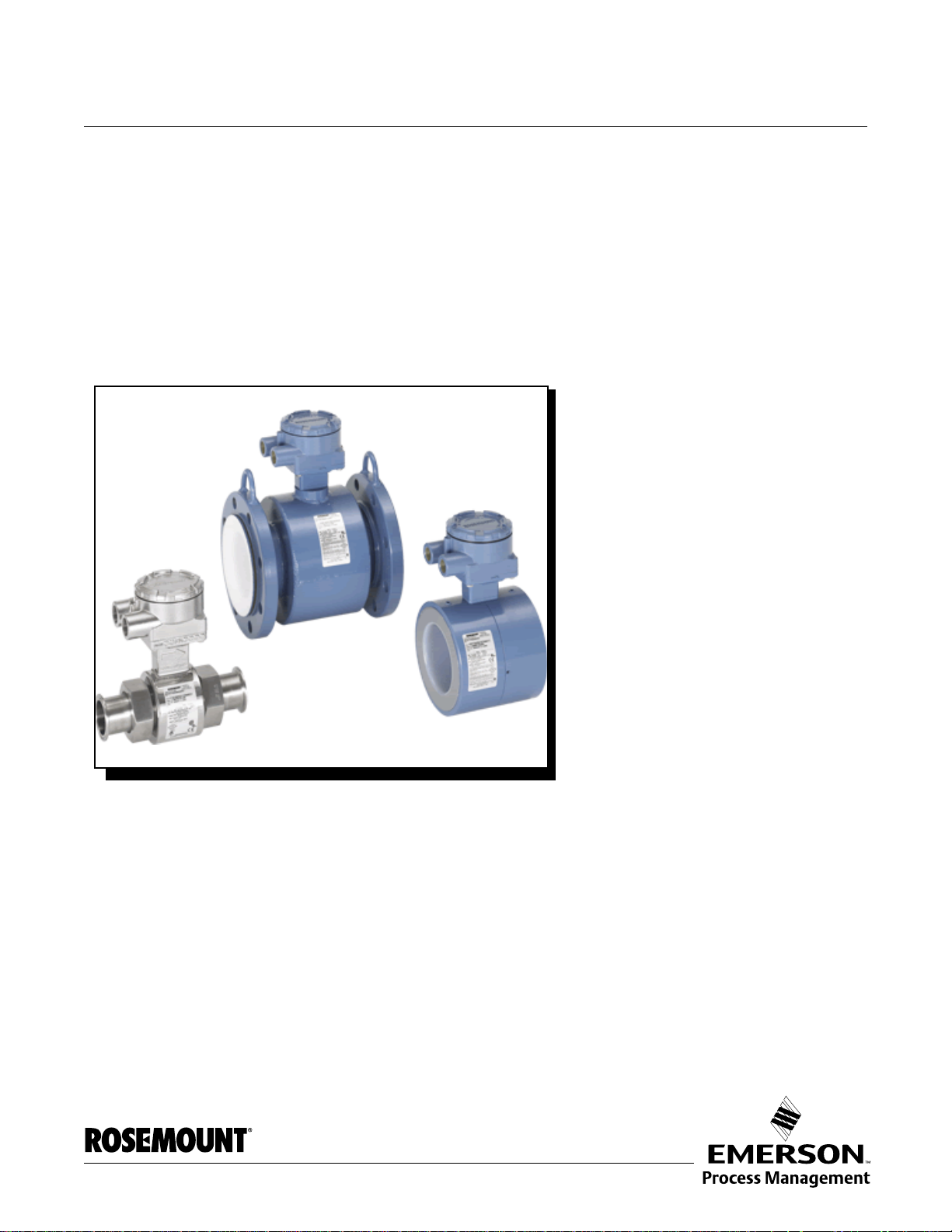
Rosemount 8700 Series
MANUAL DESCRIPTION The Rosemount
separate sensor and transmitter units. This manual is design ed to assist in the
installation and operation of Rosemount 8705, 8707 High -Signal, and 8711
Magnetic Flowmeter Sensor.
Attempting to install and operate the Rosemount 8705, 8707 High-Signal, or 8711
Magnetic Flowmeter Sensor without reviewing the instructions contained in this manual
could result in personal injury or equipment damage.
Section 1: Introduction
• Manual description
• Safety information
• Return of material
Section 2: Installation
• Installation instructions
Section 3: Operation and Maintenance
• Sensor calibration number
• Sensor configuration information.
®
Series 8700 Magnetic Flowmeter System combines
www.rosemount.com
Section 4: Maintenance and Troubleshooting
• Troubleshooting procedures
• Electrical circuit diagrams
Appendix A: Reference Data
• Instructions for removing and replacing the field-removable
electrode assembly
Appendix B: ApprovalsAppendix B: Approvals
• Approved Manufacturing Locations
• European Directive Information
• Hazardous Locations Product Approvals Offering
• Hazardous Location Certifications
Page 8
Reference Manual
See “Safety Information” on page 4-1 for complete warning information.
00809-0100-4727, Rev EA
Rosemount 8700 Series
October 2010
SAFETY INFORMATION Procedures and instructions in this manual may require special preca utions to
ensure the safety of the personnel performing the operations. Refer to the
safety messages listed at the beginning of each section before performing
any operations.
RETURN OF MATERIALS To expedite the return process outside the United States, contact the nearest
Rosemount representative.
Within the United States and Canada, call the North American Response
Center using the 800-654-RSMT (7768) toll-free number. The Response
Center, available 24 hours a day, will assist you with any needed information
or materials.
The center will ask for product model and serial numbers, and will provide a
Return Material Authorization (RMA) number. The center will also ask for the
name of the process material to which the product was last exposed.
Mishandling products exposed to a hazardous subst ance may result in death
or serious injury. If the product being returned was exposed to a hazardous
substance as defined by OSHA, a copy of the required Material Safety Data
Sheet (MSDS) for each hazardous substance identified must be included with
the returned goods.
The North American Response Center will detail the additional information
and procedures necessary to return goods exposed to hazardous
substances.
1-2
Page 9
Reference Manual
00809-0100-4727, Rev EA
October 2010
Section 2 Installation
Safety Messages . . . . . . . . . . . . . . . . . . . . . . . . . . . . . . . . . page 2-1
Sensor Handling . . . . . . . . . . . . . . . . . . . . . . . . . . . . . . . . . page 2-3
Sensor Mounting . . . . . . . . . . . . . . . . . . . . . . . . . . . . . . . . page 2-4
Installation (Flanged Sensor) . . . . . . . . . . . . . . . . . . . . . . page 2-7
Installation (Wafer Sensor) . . . . . . . . . . . . . . . . . . . . . . . . page 2-10
Installation (Sanitary Sensor) . . . . . . . . . . . . . . . . . . . . . . page 2-12
Process Leak Protection (Optional) . . . . . . . . . . . . . . . . . page 2-13
Process Leak Protection (Optional) . . . . . . . . . . . . . . . . . page 2-13
Sensor Connections . . . . . . . . . . . . . . . . . . . . . . . . . . . . . . page 2-18
This section covers the steps required to physically install the magnetic
sensor. Instructions and procedures in this section may require special
precautions to ensure the safety of the personnel performing the operations.
Please refer to the following safety messages before performing any
operation in this section.
Rosemount 8700 Series
SAFETY MESSAGES This symbol is used throughout this manual to indicate that special attention
to warning information is required.
Failure to follow these installation guidelines could result in death or serious injury:
Installation and servicing instructions are for use by qualified personnel only. Do not perform
any servicing other than that contained in the operating instructions, unless qualified. Verify
that the operating environment of the sensor and transmitter is consistent with the
appropriate hazardous area approval.
Do not connect a Rosemount transmitter to a non-Rosemount sensor that is located in an
explosive atmosphere.
www.rosemount.com
Page 10
Rosemount 8700 Series
Explosions could result in death or serious injury:
Installation of this transmitter in an explosive environment must be in accordance with the
appropriate local, national, and international standards, codes, and practices. Please review
the approvals section of this reference manual for any restrictions associated with a safe
installation.
Electrical shock can result in death or serious injury
Avoid contact with the leads and terminals. High voltage that may be present on leads can
cause electrical shock.
The sensor liner is vulnerable to handling damage. Never place anything through the sensor
for the purpose of lifting or gaining leverage. Liner damage can render the sensor useless.
To avoid possible damage to the sensor liner ends, do not use metallic or spiral-wound
gaskets. If frequent removal is anticipated, take precautions to protect the liner ends. Short
spool pieces attached to the sensor ends are often used for protection.
Correct flange bolt tightening is crucial for proper sensor operation and life. All bolts must be
tightened in the proper sequence to the specified torque limits. Failure to observe these
instructions could result in severe damage to the sensor lining and possible sensor
replacement.
Emerson Process Management can supply lining protectors to prevent liner damage during
removal, installation, and excessive bolt torquing.
Reference Manual
00809-0100-4727, Rev EA
October 2010
2-2
Page 11
Reference Manual
See ”Safety Messages” on pages 2-1 and 2-2 for complete warning information.
Without Lifting Lugs
With Lifting Lugs
00809-0100-4727, Rev EA
October 2010
Rosemount 8700 Series
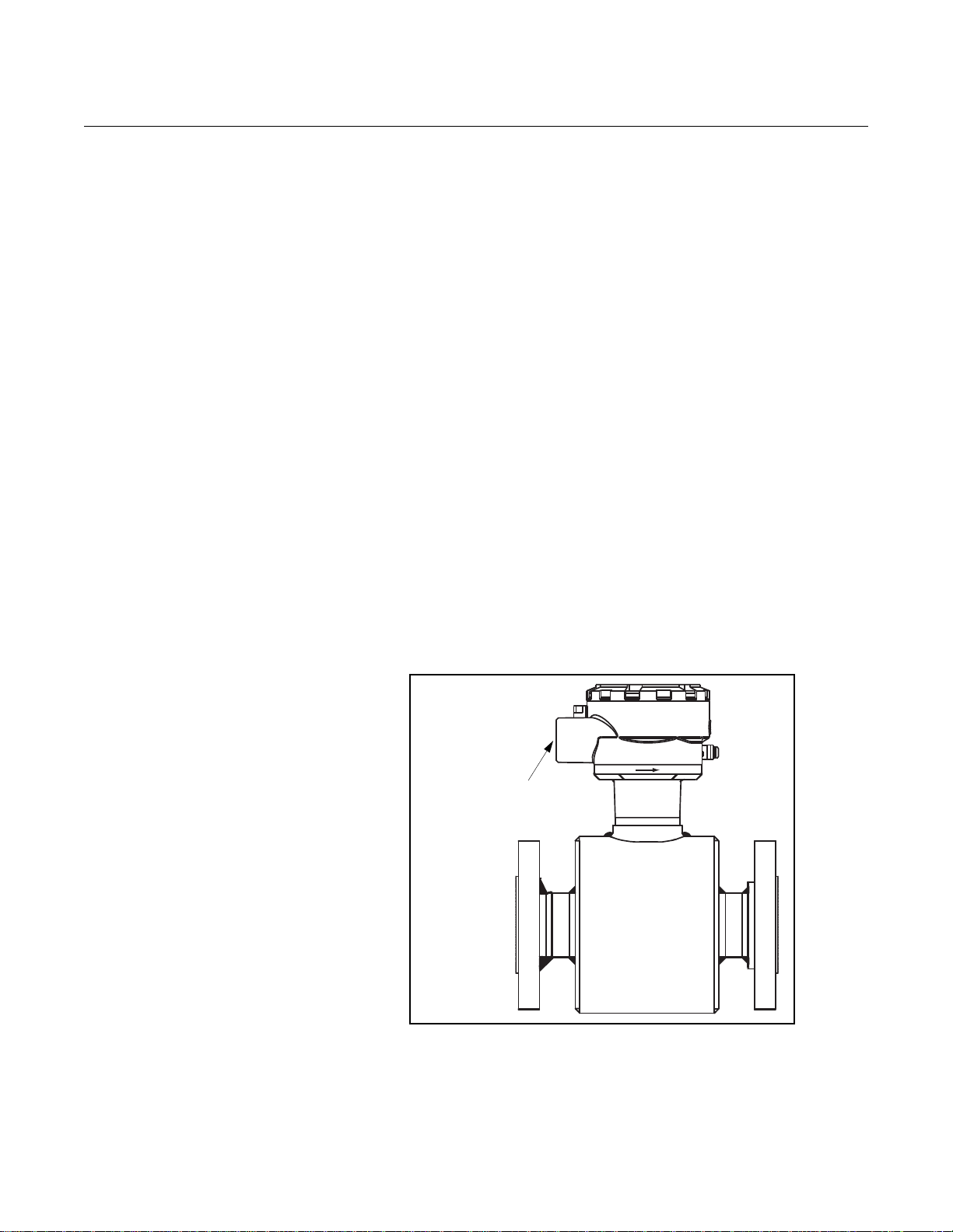
SENSOR HANDLING Handle all parts carefully to prevent damage. Whenever possible, transport
the system to the installation site in the original shipping containers.
PTFE-lined sensors are shipped with end covers that protect it from both
mechanical damage and normal unrestrained distortion. Remove the end
covers just before installation.
Flanged sensors with a lifting lug on each flange make the sensor easier to
handle when it is transported and lowered into place at the installation site.
Flanged sensors that do not have lugs must be supported with a lifting sling
on each side of the housing.
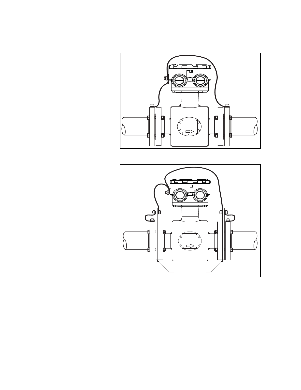
Figure 2-1 shows sensors correctly supported for handling and installation.
Notice the plywood end pieces are still in place to protect the sensor liner
during transportation.
Figure 2-1. Rosemount 8705
Sensor Support for Handling
2-3
Page 12
Reference Manual
FLOW
5 Pipe Diameters
2 Pipe Diameters
FLOW
FLOW
00809-0100-4727, Rev EA
Rosemount 8700 Series
October 2010
SENSOR MOUNTING Physical mounting of a sensor is similar to installing a typical section of pipe.
Conventional tools, equipment, and accessories (bolts, gaskets, and
grounding hardware) are required.
Upstream/Downstream
Piping
Figure 2-2. Upstream and
Downstream
Straight Pipe Diameters
To ensure specification accuracy over widely varying process conditions,
install the sensor a minimum of five straight pipe diameters upstream and two
pipe diameters downstream from the electrode plane (see Figure 2-2).
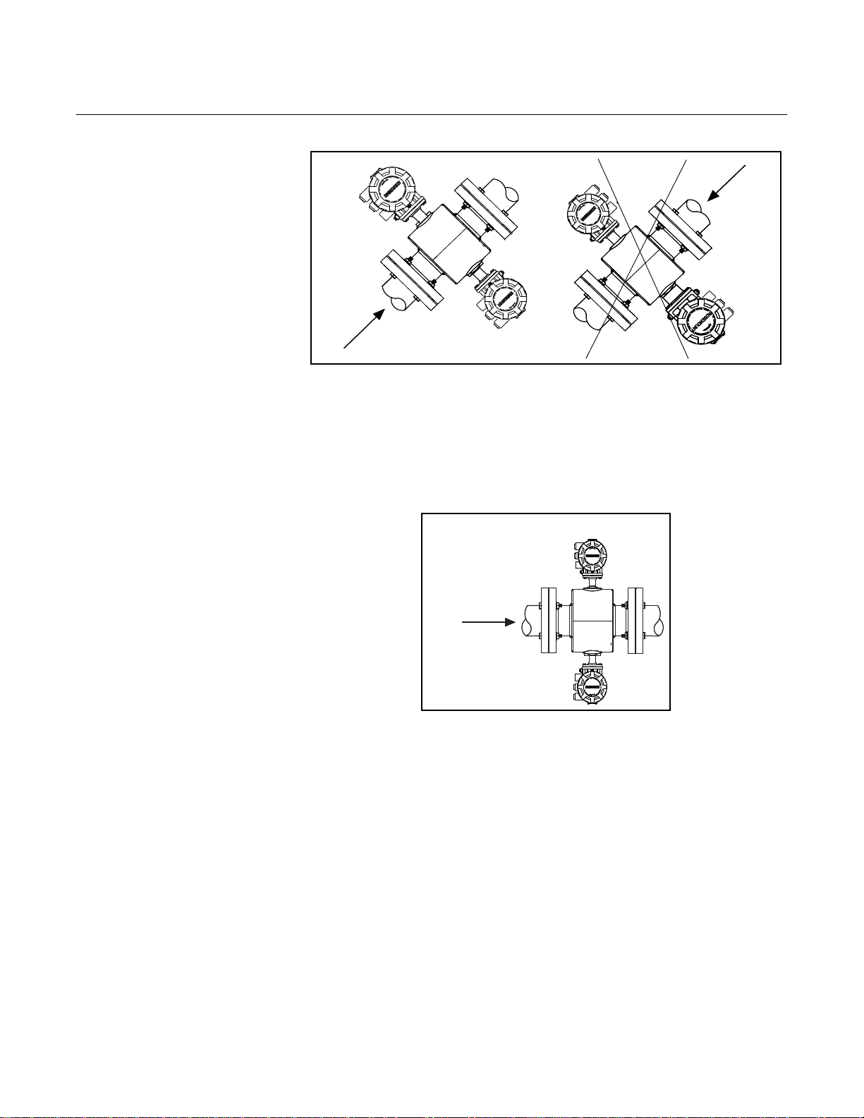
Sensor Orientation The sensor should be installed in a position that ensures the sensor remains
full during operation. Figures 2-3, 2-4, and 2-5 show the proper sensor
orientation for the most common installations. The following orientations
ensure that the electrodes are in the optimum plane to minimize the ef fects of
entrapped gas.
Vertical installation allows upward process fluid flow and is generally
preferred. Upward flow keeps the cross-sectional area full, regardless
of flow rate. Orientation of the electrode plane is unimportant in vertical
installations. As illustrated in Figures 2-3 and 2-4, avoid downward flows
where back pressure does not ensure that the se nsor remains full at all times.
Figure 2-3. Vertical Sensor
Orientation
Installations with reduced straight runs from 0 to five pipe diameters are
possible. In reduced straight pipe run installations, performance will shift to as
much as 0.5% of rate. Reported flow rates will still be highly repeatable.
2-4
Page 13
Reference Manual
FLOW
FLOW
FLOW
00809-0100-4727, Rev EA
October 2010
Figure 2-4. Incline or Decline
Orientation
Rosemount 8700 Series
Horizontal installation should be restricted to low piping sections that are
normally full. Orient the electrode plane to within 45 degrees of horizontal in
horizontal installations. A deviation of more than 45 degrees of horizontal
would place an electrode at or near the top of the sensor thereby making it
more susceptible to insulation by air or entrapped gas at the top of the
sensor.
Figure 2-5. Horizontal Sensor
Orientation
2-5
Page 14
Rosemount 8700 Series
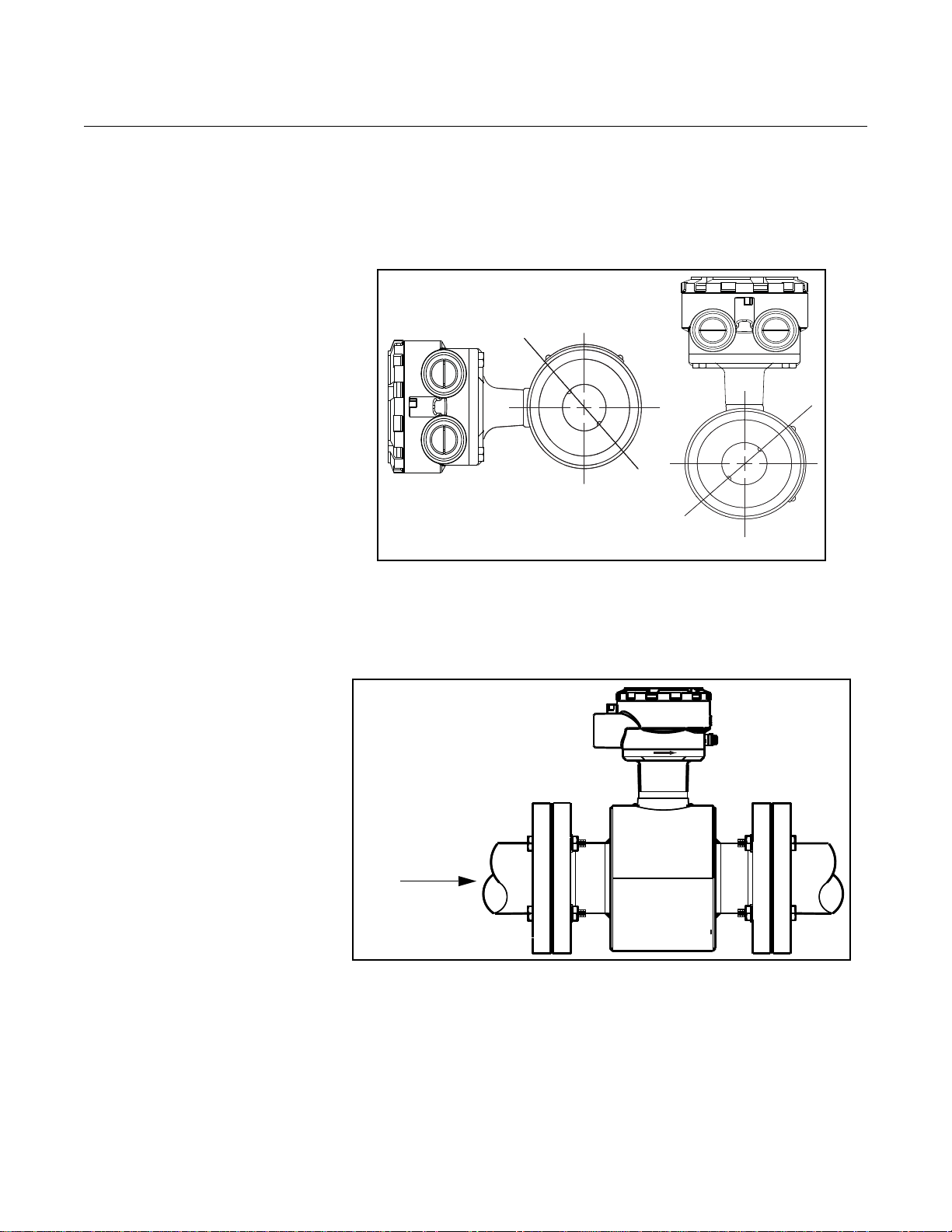
The electrodes in the Rosemount 8711 are properly oriented when the top of
the sensor is either vertical or horizontal, as shown in Figure 2-6. Avoid any
mounting orientation that positions the top of the sensor at 45 degrees from
the vertical or horizontal position.
Figure 2-6. Rosemount 8711
Mounting Position
Reference Manual
00809-0100-4727, Rev EA
October 2010
45° Electrode Plane
45° Electrode Plane
Flow Direction The sensor should be mounted so that the FORWARD end of the flow arrow,
shown on the sensor identification tag, points in the direction of flow through
the sensor (see Figure 2-7).
Figure 2-7. Flow Direction
FLOW
2-6
Page 15
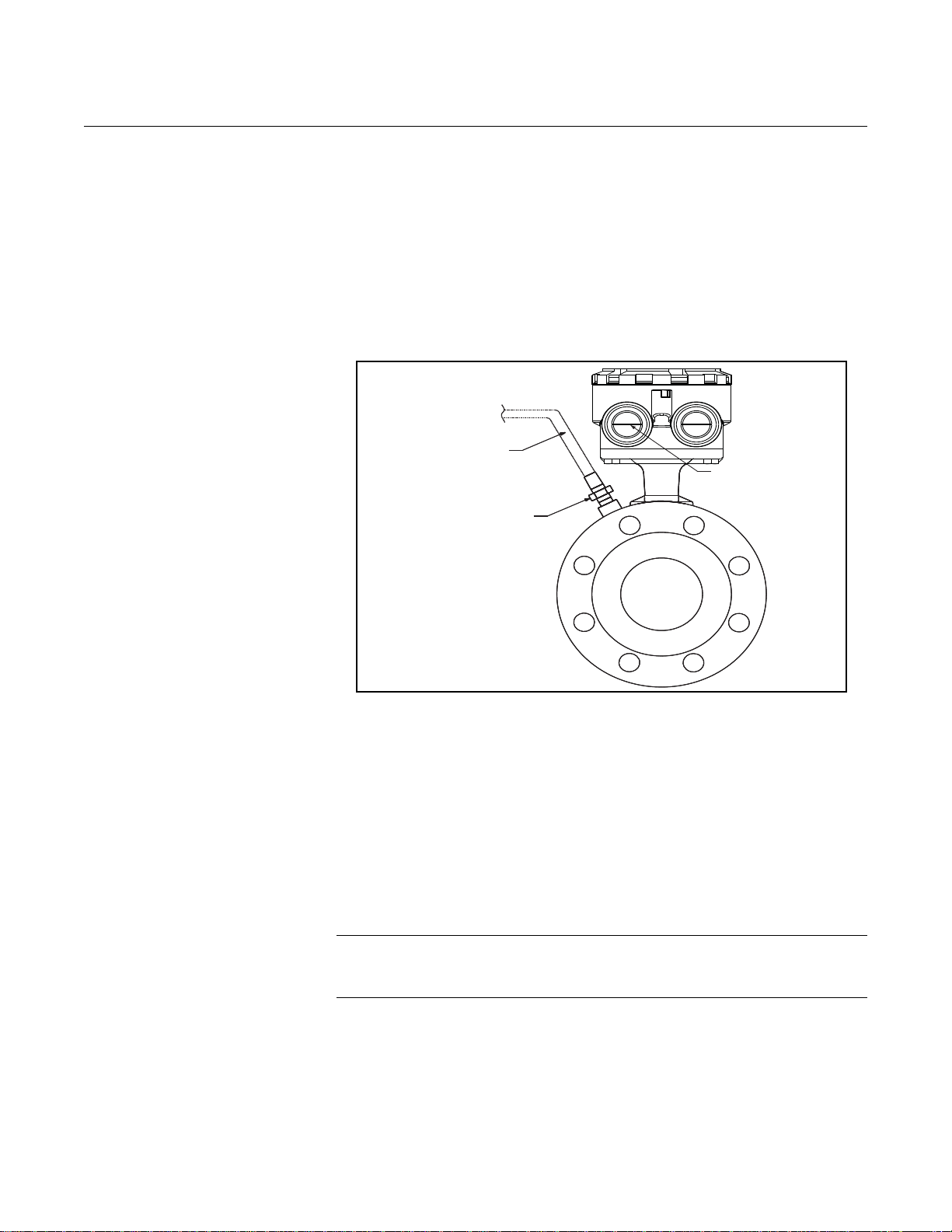
Reference Manual
See ”Safety Messages” on pages 2-1 and 2-2 for complete warning information.
Gasket (Supplied by user)
Gasket (Supplied by user)
Grounding Ring
Gasket (Supplied by user)
00809-0100-4727, Rev EA
October 2010
Rosemount 8700 Series
INSTALLATION (FLANGED SENSOR)
The following section should be used as a guide in the installation of the
flange-type Rosemount 8705 and Rosemount 8707 High-Signal Sensors.
Refer to page 2-10 for installation of the wafer-type Rosemount 8711 Sensor.
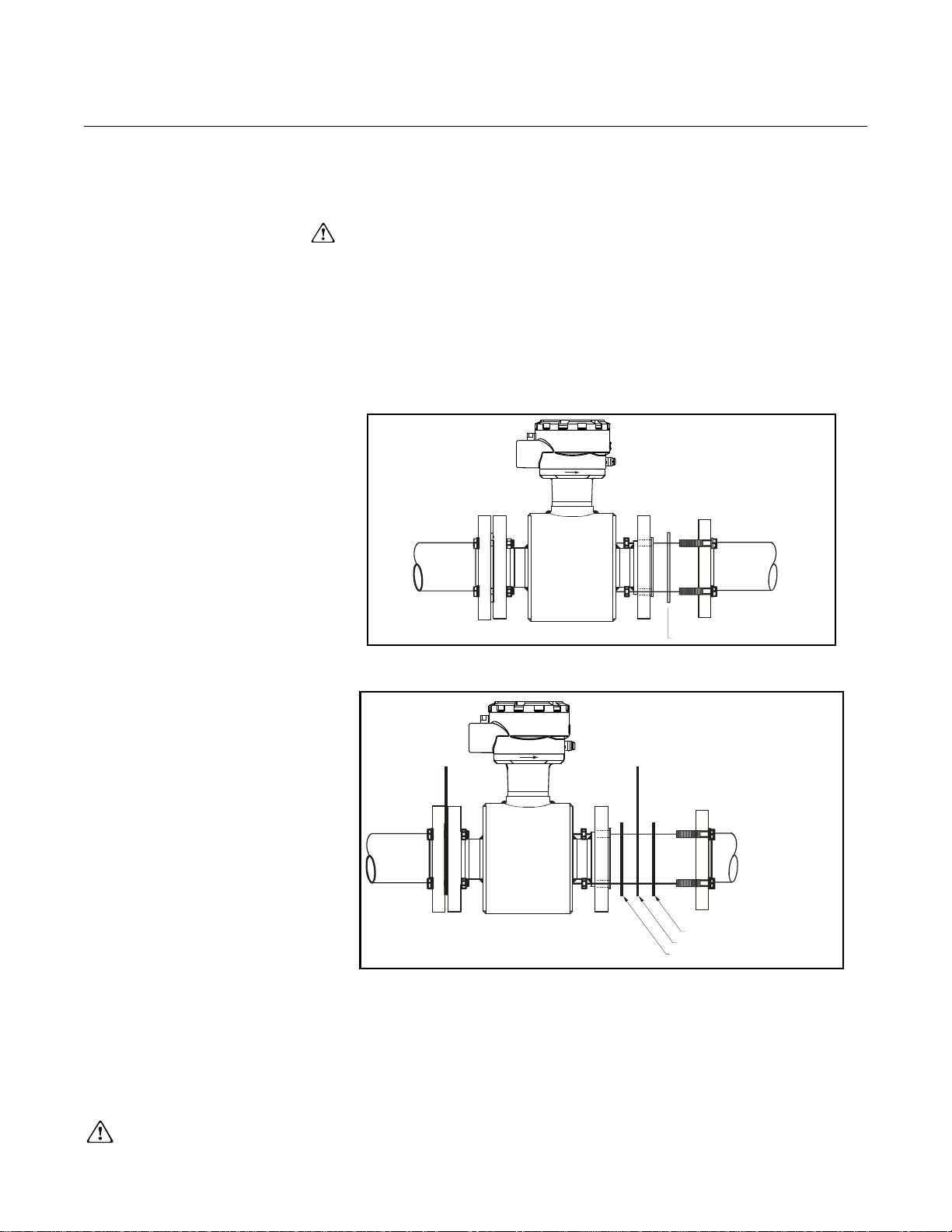
Gaskets The sensor requires a gasket at each of its connections to adjacent devices or
piping. The gasket material selected must be compatible with the process fluid and
operating conditions. Metallic or spiral-wound gaskets can damage the
liner. If the gaskets will be removed frequently, protect the liner ends. All other
applications (including sensors with lining protectors or a grounding electrode)
require only one gasket on each end connection, as shown in Figure 2-8. If
grounding rings are used, gaskets are required on each side of the groundin g
ring, as shown in Figure 2-9.
Figure 2-8. Gasket Placement
Figure 2-9. Gasket Placement
with Non-attached Grounding
Rings
Flange Bolts Suggested torque values by sensor line size and liner type are listed in Table
2-1 on page 2-8 for ASME B16.5 (ANSI) flanges and Table 2-2 and Table 2-3
for DIN flanges. Consult the factory for other flange ratings. Tighten flange
bolts in the incremental sequence as shown in Figure 2- 10. See Table 2-1 and
Table 2-2 for bolt sizes and hole diameters.
2-7
Page 16
Rosemount 8700 Series
See ”Safety Messages” on pages 2-1 and 2-2 for complete warning information.
NOTE
Do not bolt one side at a time. Tighten each side simultaneously. Example:
1. Snug left
2. Snug right
3. Tighten left
4. Tighten right
Do not snug and tighten the upstream side and then snug and tighten the
downstream side. Failure to alternate between the upstream a nd downstream
flanges when tightening bolts may result in liner damage.
Always check for leaks at the flanges after tightening the flange bolts. Failure
to use the correct flange bolt tightening methods can result in severe dam age.
All sensors require a second torquing 24 hours after initial flange bolt
tightening.
Table 2-1. Flange Bolt Torque Specifications for Rosemount 8705 and 8707
High-Signal Sensors
Size
Code
005 0.5-in. (15 mm) 8 8 8 8 010 1- in. (25 mm) 8 12 13 13 015 1.5-in. (40 mm) 13 25 29 29 7
020 2-in. (50 mm) 19 17 20 20 14
030 3-in. (80 mm) 34 35 41 41 23
040 4-in. (100 mm) 26 50 68 68 17
060 6-in. (150mm) 45 50 77 77 30
080 8-in. (200 mm) 60 82 121 121 42
100 10-in. (250 mm) 55 80 129 129 40
120 12-in. (300 mm) 65 125 146 146 55
140 14-in. (350 mm) 85 110 194 194 70
160 16-in. (400 mm) 85 160 274 274 65
180 18-in. (450 mm) 120 170 432 432 95
200 20-in. (500 mm) 110 175 444 444 90
240 24-in. (600 mm) 165 280 731 731 140
300 30-in. (750 mm) 195 375 - - 165
360 36-in. (900 mm) 280 575 - - 245
(1) Derated available with PTFE lining only.
For sensors with ANSI 600# full rated, 900#, 1500#, and 2500# flanges, the
liner is protected from over-compression by the flange design. Standard
flange torque specifications as determined by ANSI and ASME should be
followed. No special precaution is required to prevent liner damage caused by
over torquing. Bolt tightening procedures laid out in this Quick Installation
Guide must still be followed.
Line Size
Reference Manual
00809-0100-4727, Rev EA
October 2010
PTFE/ETFE liner Polyurethane liner
(1)
Class 150
(pound-feet)
Class 150
(pound-feet)
Class 300
(pound-feet)
Class 600
(Derated to
1000 psi)
Class 300
(pound-feet)
To prevent liner damage on any magnetic flowmeter, a flat gasket must be
used. For optimum results on meters with high pressure flanges (ANSI 600#
or above), it is recommended that a flat full face gasket be used.
Under NO circumstances should a spiral wound or flexitallic gasket be used
as this will damage the liner sealing surface.
2-8
Page 17
Reference Manual
4-Bolt
8-Bolt
12-Bolt
14-Bolt
20-Bolt
Torque the flange bolts
in increments according to
the above numerical sequence.
00809-0100-4727, Rev EA
October 2010
Table 2-2. Flange Bolt Torque and Bolt Load Specifications for Rosemount 8705
PTFE/ETFE liner
Size
Code
0051/2-in. (15 mm) 7 3209 7 3809 7 3809 7 4173
010 1-in. (25 mm) 13 6983 13 6983 13 6983 13 8816
015 11/2-in. (40 mm) 24 9983 24 9983 24 9983 24 13010
020 2-in. (50 mm) 25 10420 25 10420 25 10420 25 14457
030 3-in. (80 mm) 14 5935 14 5935 18 7612 18 12264
040 4-in. (100 mm) 17 7038 17 7038 30 9944 30 16021
060 6-in. (150mm) 23 7522 32 10587 60 16571 60 26698
080 8-in. (200 mm) 35 11516 35 11694 66 18304 66 36263
100 10-in. (250 mm) 31 10406 59 16506 105 25835 105 48041
120 12-in. (300 mm) 43 14439 82 22903 109 26886 109 51614
140 14-in. (350 mm) 42 13927 80 22091 156 34578 156 73825
160 16-in. (400 mm) 65 18189 117 28851 224 45158 224 99501
180 18-in. (450 mm) 56 15431 99 24477 — — — 67953
200 20-in. (500 mm) 66 18342 131 29094 225 45538 225 73367
240 24-in. (600 mm) 104 25754 202 40850 345 63940 345 103014
Line Size (Newton-meter) (Newton) (Newton-meter) (Newton) (Newton-meter) (Newton) (Newton-meter) (Newton)
PN10 PN 16 PN 25 PN 40
Rosemount 8700 Series
Figure 2-10. Flange Bolt
To rquing Sequence
2-9
Page 18
Reference Manual
00809-0100-4727, Rev EA
Rosemount 8700 Series
Table 2-3. Flange Bolt Torque and Bolt Load Specifications for Rosemount 8705
Polyurethane Liner
Size
Code
0051/2-in. (15 mm) 1 521 1 826 2 1293 6 3333
010 1-in. (25 mm) 2 1191 3 1890 5 2958 10 5555
015 11/2-in. (40 mm) 5 1960 7 3109 12 4867 20 8332
020 2-in. (50 mm) 6 2535 10 4021 15 6294 26 10831
030 3-in. (80 mm) 5 2246 9 3563 13 5577 24 19998
040 4-in. (100 mm) 7 3033 12 4812 23 7531 35 11665
060 6-in. (150mm) 16 5311 25 8425 47 13186 75 20829
080 8-in. (200 mm) 27 8971 28 9487 53 14849 100 24687
100 10-in. (250 mm) 26 8637 49 13700 87 21443 155 34547
120 12-in. (300 mm) 36 12117 69 19220 91 22563 165 36660
140 14-in. (350 mm) 35 11693 67 18547 131 29030 235 47466
160 16-in. (400 mm) 55 15393 99 24417 189 38218 335 62026
200 20-in. (500 mm) 58 15989 114 25361 197 39696 375 64091
240 24-in. (600 mm) 92 22699 178 36006 304 56357 615 91094
Line Size
(Newton-meter) (Newton) (Newton-meter) (Newton) (Newton-meter) (Newton) (Newton-meter) (Newton)
PN 10 PN 16 PN 25 PN 40
October 2010
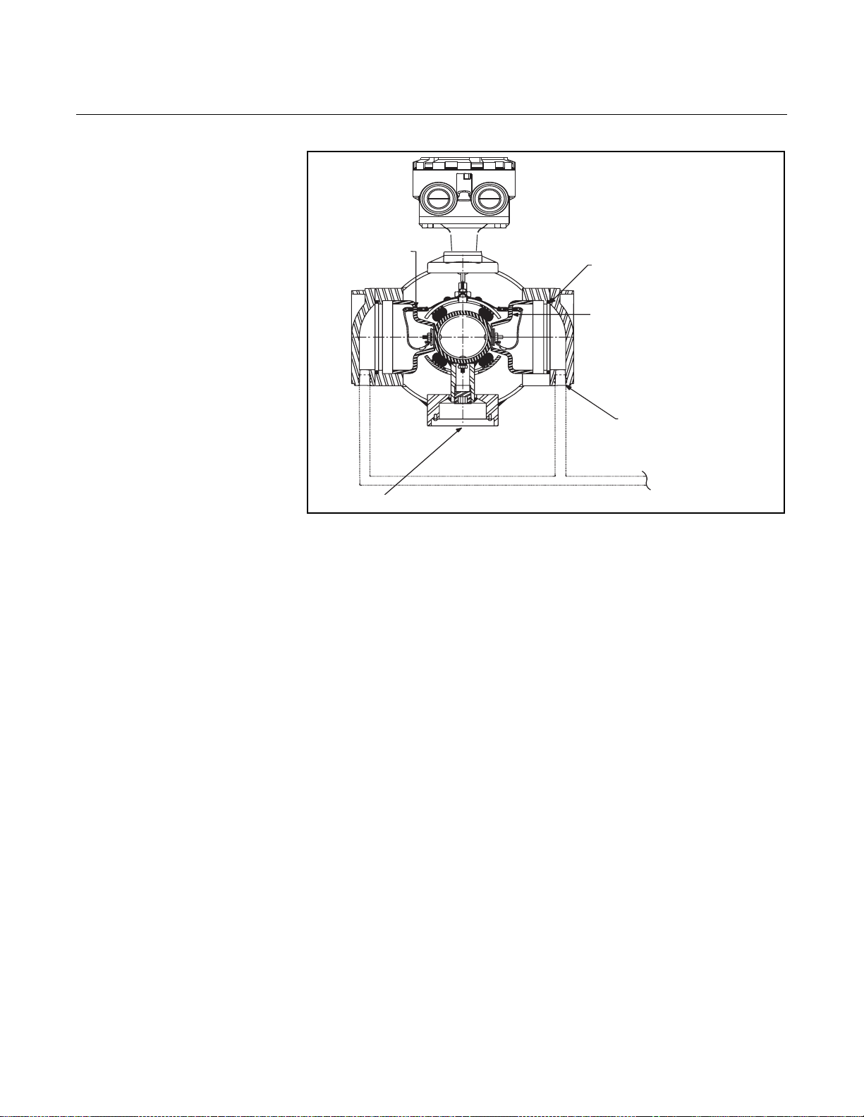
INSTALLATION (WAFER SENSOR)
The following section should be used as a guide in the installation of the
Rosemount 8711 Sensor. Refer to page 2-7 for installation of the flange-type
Rosemount 8705 and 8707 High-Signal sensor.
Gaskets The sensor requires a gasket at each of its connections to adjacent devices or
piping. The gasket material selected must be compatible with the process
fluid and operating conditions. Metallic or spiral-wound gaskets can
damage the liner. If the gaskets will be removed frequently, protect the
liner ends. If grounding rings are used, a gasket is required on each side of
the grounding ring.
Alignment and Bolting
1. On 11/2 - through 8-in. (40 through 200 mm) line sizes, place centering
rings over each end of the sensor. The smaller line sizes, 0.15through 1-in. (4 through 25 mm), do not require centering rings.
2. Insert studs for the bottom side of the sensor between the pipe
flanges. Stud specifications are listed in Table 2-4. Using carbon
steel bolts on smaller line sizes, 0.15- through 1-in.
(4 through 25 mm), rather than the required stainless steel bolts,
will degrade performance.
2-10
Page 19
Reference Manual
00809-0100-4727, Rev EA
October 2010
Rosemount 8700 Series
Table 2-4. Stud Specifications
Nominal Sensor Size Stud Specifications
0.15 – 1-in. (4 – 25 mm) 316 SST ASTM A193, Grade B8M
Class 1 threaded mounted studs
11/2 – 8-in. (40 – 200 mm) CS, ASTM A193, Grade B7, threaded mounting studs
3. Place the sensor between the flanges. Make sure that the centering
rings are properly placed in the studs. The studs should be aligned
with the markings on the rings that correspond to the flange you are
using.
4. Insert the remaining studs, washers, and nuts.
5. Tighten to the torque specifications shown in Table 2-5. Do not
overtighten the bolts or the liner may be damaged.
NOTE
On the 4- and 6- in. PN 10-16, insert the sensor with rings first and then insert
the studs. The slots on this ring scenario are located on the inside of the ring.
Figure 2-11. Gasket Placement
with Centering Rings
Centering Rings
Installation, Studs
Nuts and Washers
Customer-supplied
Gasket
FLOW
Flange Bolts Sensor sizes and torque values for both Class 1 50 and Class 300 flan ges are
listed in Table 2-5. Tighten flange bolts in the incremental sequence, shown in
Figure 2-10.
NOTE
Do not bolt one side at a time. Tighten each side simultaneously. Example:
1. Snug left
2. Snug right
3. Tighten left
4. Tighten right
Do not snug and tighten the upstream side and then snug and tighten the
downstream side. Failure to alternate between the upstream and downstream
flanges when tightening bolts may result in liner damage.
Always check for leaks at the flanges after tightening the flange
bolts. All sensors require a second torquing 24 hours after initial flange bolt
tightening.
See ”Safety Messages” on pages 2-1 and 2-2 for complete warning information.
2-11
Page 20
Reference Manual
User supplied clamp
User supplied gasket
00809-0100-4727, Rev EA
Rosemount 8700 Series
October 2010
Table 2-5. Flange bolt Torque Specifications of Rosemount 8711 Sensors
Size Code Line Size Pound-feet Newton-meter
15F 0.15-in. (4 mm) 5 6.8
30F 0.30-in. (8 mm) 5 6.8
005
010 1-in. (25 mm) 10 13.6
015 11/2-in. (40 mm) 15 20.5
020 2-in. (50 mm) 25 34.1
030 3-in. (80 mm) 40 54.6
040 4-in. (100 mm) 30 40.1
060 6-in. (150 mm) 50 68.2
080 8-in. (200 mm) 70 81.9
1
/2-in. (15 mm) 5 6.8
INSTALLATION (SANITARY SENSOR)
Gaskets The sensor requires a gasket at each of its connections to adjacent devices or
piping. The gasket material selected must be compatible with the process
fluid and operating conditions. Gaskets ar e supplied with all Rosemo unt 8721
Sanitary sensors except when the process connection is an IDF sanitary
screw type.
Alignment and Bolting Standard plant practices should be followed when installing a magmeter with
Figure 2-12. Rosemount 8721
Sanitary Installation
sanitary fittings. Unique torque values and bolting techniq ue s ar e no t
required.
2-12
Page 21
Reference Manual
1
/2–14 NPT Conduit
Connection
(no relief valve)
00809-0100-4727, Rev EA
October 2010
Rosemount 8700 Series
PROCESS LEAK PROTECTION (OPTIONAL)
Standard Housing
Configuration
The Rosemount 8705 and 8707 High-Signal Sensor housing is fabricated
from carbon steel to perform two separate functions. First, it provides
shielding for the sensor magnetics so that external disturbances cannot
interfere with the magnetic field and thus affect the flow measu re m en t.
Second, it provides the physical protection to the coils and other internal
components from contamination and physical d amage that might occur in an
industrial environment. The housing is completely welded and gasket-free.
The three housing configurations are identified by the W0, W1, or W3 in the
model number option code when ordering. Below are brief description s of
each housing configuration, which are followed by a more detailed overview.
• Code W0 — sealed, welded coil housing (standard configuration)
• Code W1 — sealed, welded coil housing with a relief valve capable of
venting fugitive emissions to a safe location (additional plumbing from
the sensor to a safe area, installed by the user, is required to vent
properly)
• Code W3 — sealed, welded coil housing with separate electrode
compartments capable of venting fugitive emissions (additional
plumbing from the sensor to a safe area, installed by the user, is
required to vent properly)
The standard housing configuration is identified by a code W0 in the model
number. This configuration does not provide separate electrode
compartments with external electrode access. In the even t of a pr oc es s leak,
these models will not protect the coils or other sensitive areas around the
sensor from exposure to the pressure fluid (Figure 2-13).
Figure 2-13. Standard Housing
Configuration — Sealed Welded
Housing (Option Code W0)
2-13
Page 22
Reference Manual
00809-0100-4727, Rev EA
Rosemount 8700 Series
October 2010
Relief Valves The first optional configuration, identified by the W1 in the model number
option code, uses a completely welded coil housing. This configuration does
not provide separate electrode compartments with external electrode access.
This optional housing configuration provides a relief valve in the housing to
prevent possible overpressuring, caused by damage to the lining or other
situations that might allow process pressure to enter the housing. The relief
valve will vent when the pressure inside the sensor housing exceeds five psi.
Additional piping (provided by the user) may be connected to this relief valve
to drain any process leakage to safe containment (see Figure 2-14).
Figure 2-14. Coil-Housing
Configuration — Standard
Welded Housing With Relief
Valve (Option Code W1)
Optional:
Use drain port to
plumb to a safe area
(Supplied by user)
¼'' NPT – 5 psi
Pressure Relief Valve
1
/2 – 14 NPT Conduit
Connection
Process Leak
Containment
The second optional configuration, identified as option code W3 in the model
number, divides the coil housing into three compartments: one for each
electrode and one for the coils. Should a damaged liner or electrode fault
allow process fluid to migrate behind the electrode seals, the fluid is cont ained
in the electrode compartment. The sealed electrode compartment prevents
the process fluid from entering the coil compartment wh er e it woul d dam ag e
the coils and other internal components.
The electrode compartments are designed to contain the process fluid at full
line pressure. An O-ring sealed cover provides access to each of the
electrode compartments from outside the sensor; drainports are provided in
each cover for the removal of fluid.
NOTE
The electrode compartment could contain full line pressure and it must be
depressurized before the cover is removed.
2-14
Page 23
Reference Manual
00809-0100-4727, Rev EA
October 2010
Figure 2-15. Housing
Configuration — Sealed
Electrode Compartment (Option
Code W3)
Rosemount 8700 Series
Conduit Ports and
Connections
Fused Glass Seal
Grounding Electrode Port
O-ring Seal
Sealed Electrode Compartment
1
/2 - 27 NPT
Optional:
Use drain port to
plumb to a safe area
(Supplied by user)
If necessary, capture any process fluid leakage, connect the appropriate
piping to the drainports, and provide for proper disposal (see Figure 2-15).
Both the sensor and transmitter junction boxes have ports for 1/2-in. NPT
conduit connections, with optional CM20 and PG 13.5 adapter connections
available. These connections should be made in accordance with national,
local or plant electrical codes. Unused ports should be sealed with metal
plugs and PTFE tape or other thread sealant. Connections should also be
made in accordance with area approval require m ents, see exam ples below
for details. Proper electrical installation is necessary to prevent errors due to
electrical noise and interference. Separate conduits are not necessary for the
coil drive and signal cables connecting the transmitter to the sensor, but a
dedicated conduit line between each transmitter and sensor is required. A
shielded cable must be used.
Example 1: Installing flanged sensors into an IP68 area. Sensors must be
installed with IP68 cable glands and cable to maintain IP68 rating. Unused
conduit connections must be properly sealed to prevent water ingress. For
added protection, dielectric gel can be used to pot the sensor terminal block.
Consult technical document 00840-0100-4750 when installing meters into an
IP68 installation.
Example 2: Installing flowmeters into explosion-proof/flameproof areas.
Conduit connections and conduit must be rated for use in the hazardous area
to maintain flowmeter approval rating. Consult Appendix B: of this manual for
installation requirements for hazardous areas.
2-15
Page 24
Reference Manual
NOTE
Dimensions are in
inches
(millimeters).
1.00
(26)
Cable Shield
00809-0100-4727, Rev EA
Rosemount 8700 Series
October 2010
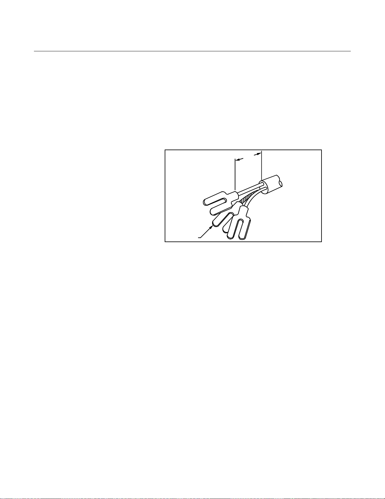
Conduit Cables Run the appropriate size cable through the conduit connections in your
magnetic flowmeter system. Run the power cable from the power source to
the transmitter . Do n ot run power cab les and outpu t signal cables in the same
conduit. For remote mount installations, run the coil drive and electrode
cables between the flowmeter and transmitter. Refer to Electrical
Considerations for wire type. Prepare the ends of the coil drive and electrode
cables as shown in Figure 2-16. Limit the unshielded wire length to 1-in. on
both the electrode and coil drive cables. Excessive lead length or failure to
connect cable shields can create electrical noise, resulting in unstable meter
readings.
Figure 2-16. Cable Preparation
Detail
2-16
Page 25
Reference Manual
00809-0100-4727, Rev EA
October 2010
Rosemount 8700 Series
Electrical Considerations Before making any electri cal connections to the Rosemount transmitter,
consider the following standards and be sure to have the proper power
supply, conduit, and other accessories. When preparing all wire connections,
remove only the insulation required to fit the wire completely under the
terminal connection. Removal of excessive insulation may result in an
unwanted electrical short to the transmitter housing or other wire connections.
Transmitter Input Power
The Rosemount transmitter is designed to be powered b y 90 -25 0 Vac, 50–60
Hz or 12–42 Vdc. The eighth digit in the transmitter model number design ates
the appropriate power supply requirement.
Model Number Power Supply Requirement
1 90-250 Vac
2 12-42 Vdc
Supply Wire Temperature Rating
Use 14 to 18 AWG wire rated for the proper temperatu re of the application.
For connections in ambient temperatures above 140 °F (60 °C), use a wire
rated for 176 °F (80 °C). For ambients greater than 176 °F (80 °C), use a
wire rated for 230 °F (110 °C). For DC powered transmitters with extended
power cable lengths, verify that there is a minimum of 12 Vdc at the
terminals of the transmitter.
Disconnects
Connect the device through an external disconnect or circuit breaker.
Clearly label the disconnect or circuit breaker and locate it near the
transmitter.
Consult the applicable Rosemount Transmitter Documentation for detailed
transmitter installation instructions.
Transmitter Quick Installation Guide Manual
8732E HART 00825-0100-4662 00809-0100-4662
8732E FOUNDATION fieldbus 00825-0100-4663 00809-0100-4663
8732E Profibus PA 00825-0100-4665 00809-0100-4665
8712E HART 00825-0100-4664 00809-0100-4664
2-17
Page 26
Reference Manual
Coil Drive
and
Electrode
Cables
Power
Power
Outputs
Outputs
Coil Drive
and
Electrode
Cables
Power
Outputs
Power
Outputs
00809-0100-4727, Rev EA
Rosemount 8700 Series
October 2010
SENSOR CONNECTIONS This section covers the steps required to physically install the transmitter
including wiring and calibration.
Rosemount Sensors To connect the transmitter to a non-Rosemount sensor, refer to the
appropriate wiring diagram in “Universal Sensor Wiring Diagrams” on
page E-1. The calibration procedure listed is not required for use with
Rosemount sensors.
Transmitter to Sensor
Wiring
Figure 2-17. Conduit
Preparation
Correct Incorrect
Flanged and wafer sensors have two conduit ports as shown in Figur e 2-17.
Either one may be used for both the coil drive and electrode cables. Use the
stainless steel plug that is provided to seal the unused conduit port. Use
PTFE tape or thread sealant appropriate for the installation when sealing the
conduit.
A single dedicated conduit run for the coil drive and electrode cables is
needed between a sensor and a remote transmitter. Bundled cables in a
single conduit are likely to create interference and noise problems in your
system. Use one set of cables per conduit run. See Figure 2-17 for proper
conduit installation diagram and Table 2-6 for recommended cable. For
integral and remote wiring diagrams refer to Figure 2-18.
Table 2-6. Cable Requirements
Description Units Part Number
Signal Cable (20 AWG) Belden 8762, Alpha 2411 equivalent ft
Coil Drive Cable (14 AWG) Belden 8720, Alpha 2442 equivalent ft
Combination Signal and Coil Drive Cable (18 AWG)
(1) Combination signal and coil drive cable is not recommended for high-signal magme ter system. For remote mou nt installatio ns, combination signal and coil
2-18
drive cable should be limited to less than 330 ft. (100 m).
08712-0061-0001
m
(1)
m
ft
m
08712-0061-2003
08712-0060-0001
08712-0060-2003
08712-0752-0001
08712-0752-2003
Page 27
Reference Manual
00809-0100-4727, Rev EA
October 2010
Figure 2-18. Wiring Diagram
Rosemount 8700 Series
Rosemount recommends using the combination signal and coil drive for N5,
E5 approved sensors for optimum performance.
Remote transmitter installations require equal lengths of signal and coil drive
cables. Integrally mounted transmitters are factory wired and do not require
interconnecting cables.
Lengths from 5 to 1,000 ft. (1.5 to 300 m.) may be specified, and will be
shipped with the sensor.
Transmitter
Ter minal
1 1 14 Clear or Red
2 2 14 Black
17 17 20 Shield
18 18 20 Black
19 19 20 Clear or Red
Sensor Terminal Wire Gauge Wire Color
14 Shield
2-19
Page 28

Rosemount 8700 Series
Reference Manual
00809-0100-4727, Rev EA
October 2010
2-20
Page 29
Reference Manual
00809-0100-4727, Rev EA
October 2010
Rosemount 8700 Series
Section 3 Operation and Maintenance
Calibration . . . . . . . . . . . . . . . . . . . . . . . . . . . . . . . . . . . . . . page 3-1
Grounding . . . . . . . . . . . . . . . . . . . . . . . . . . . . . . . . . . . . . . page 3-1
Material Selection . . . . . . . . . . . . . . . . . . . . . . . . . . . . . . . . page 3-3
Magnetic Flowmeter Sizing . . . . . . . . . . . . . . . . . . . . . . . . page 3-4
This section covers basic operation, software functionality, and basic
configuration procedures for the Magnetic Sensor. For more information about
the technology and the function blocks used in the sensor, refer to
Appendix A: Reference Data and Appendix C: Field-Removable Electrodes.
CALIBRATION Rosemount sensor are wet calibrated at the factory. They do not need further
calibration during installation.
GROUNDING Process grounding the sensor is one of the most important details of sensor
installation. Proper process grounding ensures that th e transmitter amplifier is
referenced to the process. This creates the lowest noise environment for the
transmitter to make a stable reading. Use Table 3-1 to determine which
grounding option to follow for proper installation.
NOTE
Consult factory for installations requiring cathodic protection or situations
where there are high currents or high potential in the process.
The sensor case should always be earth grounded in accordance with
national and local electrical codes. Failure to do so may impair the protection
provided by the equipment. The most effective grounding method is direct
connection from the sensor to earth ground with minimal impedance.
The Internal Ground Connection (Protective Ground Connection), located
inside the junction box, is the Internal Ground Connection screw. This screw
is identified by the ground symbol:
Table 3-1. Grounding Installation
Grounding Options
Type of Pipe No Grounding Options Grounding Rings Grounding Electrodes Lining Protectors
Conductive Unlined Pipe See Figure 3-1 Not Required Not Required See Figure 3-2
Conductive Lined Pipe Insufficient Grounding See Figure 3-2 See Figure 3-1 See Figure 3-2
Non-Conductive Pipe Insufficient Grounding See Figure 3-3 See Figure 3-4 See Figure 3-3
www.rosemount.com
Page 30
Rosemount 8700 Series
Grounding Rings or
Lining Protectors
Figure 3-1. No Grounding
Options or Grounding Electrode
in Lined Pipe
Figure 3-2. Grounding with
Grounding Rings or Lining
Protectors
Reference Manual
00809-0100-4727, Rev EA
October 2010
3-2
Page 31

Reference Manual
Grounding Rings or
Lining Protectors
00809-0100-4727, Rev EA
October 2010
Figure 3-3. Grounding with
Grounding Rings or Lining
Protectors
Rosemount 8700 Series
Figure 3-4. Grounding with
Grounding Electrodes
MATERIAL SELECTION Several liner types, electrode materials, and electrode types are available on
Rosemount Magnetic Sensor to ensure compatibility with virtually any
application. See Appendix A: for information on liner types, on electrode
materials, and electrode types. For further guidance on selecting materials,
refer to the Magnetic Flowmeter Material Selection Guide located on
Rosemount.com (document number 00816-0100-3033).
3-3
Page 32

Rosemount 8700 Series
Velocity =
Flow Rate
Factor
Velocity =
Velocity = 1.7 m/s
800
(L/min.)
Velocity =
Velocity = 7.56 ft/s
300 (gpm)
39.679
Reference Manual
00809-0100-4727, Rev EA
October 2010
MAGNETIC FLOWMETER SIZING
Flowmeter Sizing
Because of its effect on flow velocity, sensor size is an important
consideration. It may be necessary to select a magnetic flowmeter that is
larger or smaller than the adjacent piping to ensure the fluid velocity is in the
specified measuring range of the sensor. Suggested guidelines and examples
for sizing normal velocities in different applications are listed in Table 3-2,
Table 3-3, and Table 3-4. Operation outside these guidelines may also give
acceptable performance.
Table 3-2. Sizing Guidelines
Application Velocity Range (ft/s) Velocity Range (m/s)
Normal Service
Abrasive Slurries
Non-Abrasive Slurries
2–20 0.6–6.1
3–10 0.9–3.1
5–15 1.5–4.6
To convert flow rate to velocity, use the appropriate factor listed in Table 3-2
and the following equation:
Example: SI Units
Magmeter Size: 100 mm (factor from Table 3-3 = 492.0)
Normal Flow Rate: 800 L/min.
3-4
Example: English Units
Magmeter Size: 4-in. (factor from Table 3-3 = 39.679)
Normal Flow Rate: 300 GPM
Page 33

Reference Manual
00809-0100-4727, Rev EA
October 2010
Rosemount 8700 Series
Table 3-3. Line Size vs. Conversion Factor
Nominal Line Size
Inches (mm)
0.30 (8) 0.220 2.732
½ (15) 0.947 11.745
1 (25) 2.693 33.407
1½ (40) 6.345 78.69
2 (50) 10.459 129.7
2 ½ (65) 14.922 185.0
3 (80) 23.042 285.7
4 (100) 39.679 492.0
6 (150) 90.048 1,116
8 (200) 155.94 1,933
10 (250) 245.78 3,048
12 (300) 352.51 4,371
14 (350) 421.70 5,229
16 (400) 550.80 6,830
18 (450) 697.19 8,645
20 (500) 866.51 10,745
24 (600) 1,253.2 15,541
30 (750) 2,006.0 24,877
36 (900) 2,935.0 36,398
Gallons Per Minute Factor
Liters Per
Minute Factor
3-5
Page 34

Reference Manual
00809-0100-4727, Rev EA
Rosemount 8700 Series
Table 3-4. Line Size vs. Velocity/Rate
Minimum/Maximum Flow Rate
Nominal
Line Size in
Inches
(mm)
.15 (4) 0.002 0.055 0.16 2.14 0.01 0.21 0.68 8.16
.30 (8) 0.009 0.220 0.66 8.58 0.03 0.83 2.73 32.76
1
/2 (15) 0.038 0.947 2.84 36.93 0.14 3.58 11.74 140.88
1 (25) 0.108 2.694 8.08 105.07 0.41 10.18 33.40 424.80
1
1
/2 (40) 0.254 6.345 19.03 247.46 0.96 23.98 78.69 944.28
2 (50) 0.418 10.459 31.37 407.90 1.58 39.54 129.7 1,556
1
2
/2 (65) 0.597 14.922 44.77 582.0 2.22 55.51 185.0 2,220
3 (80) 0.922 23.042 69.12 898.64 3.49 87.10 285.7 3,428
4 (100) 1.588 39.667 119.0 1547.0 6.00 138.6 492.0 5,904
6 (150) 3.600 90.048 270.1 3511.8 13.61 340.3 1,116 13,400
8 (200) 6.240 155.94 467.7 6081.7 23.59 589.4 1,933 23,204
10 (250) 9.840 245.78 737.3 9585.4 37.20 929.0 3,048 36,576
12 (300) 14.200 352.51 1,059 13,747 53.68 1,332 4,371 52,548
14 (350) 16.800 421.70 1,265 16,446 63.50 1,594 5,230 62,755
16 (400) 22.000 550.80 1,652 21,481 83.16 2,082 6,830 81,964
18 (450) 27.800 697.19 2,091 27,190 105.0 2,635 8,646 103,750
20 (500) 34.600 866.51 2,599 33,793 130.7 3,275 10,740 128,948
24 (600) 50.200 1,253.2 3,759 48,874 189.7 4,737 15,540 186,496
30 (750) 80.200 2,006.0 6,018 78,234 303.1 7,582 24,880 298,527
36 (900) 117.40 2,935.0 8,805 114,465 443.7 11,094 36,390 436,779
at 0.04 ft/s
(Low-flow
Cutoff)
Gallons per Minute Liters per Minute
at 1 ft/s
(Min Range
Setting)
at 3 ft/s
at 39 ft/s
(Max Range
Setting)
at 0.012 m/s
(Low-flow
Cutoff)
at 0.3 m/s
(Min Range
Setting)
at 1 m/s
October 2010
at 12 m/s
(Max Range
Setting)
3-6
Page 35

Reference Manual
00809-0100-4727, Rev EA
October 2010
Rosemount 8700 Series
Section 4 Maintenance and
Troubleshooting
Safety Information . . . . . . . . . . . . . . . . . . . . . . . . . . . . . . . page 4-1
Installation Check and Guide . . . . . . . . . . . . . . . . . . . . . . page 4-2
Diagnostic Messages . . . . . . . . . . . . . . . . . . . . . . . . . . . . . page 4-3
Transmitter Troubleshooting . . . . . . . . . . . . . . . . . . . . . . . page 4-5
Quick Troubleshooting . . . . . . . . . . . . . . . . . . . . . . . . . . . . page 4-7
This section covers basic transmitter and sensor troubleshooting. Problems in
the magnetic flowmeter system are usually indicated by incorrect output
readings from the system, error messages, or failed tests. Consider all
sources when identifying a problem in your system. If the problem persists,
consult your local Rosemount representative to determine if the material
should be returned to the factory . Emerson Process Management offers
several diagnostics that aid in the troubleshooting process.
SAFETY INFORMATION
Instructions and procedures in this section may require special precautions to
ensure the safety of the personnel performing the operations. Please read the
following safety messages before performing any operation described in this
section. Refer to these warnings when appropriate throughout this section.
Failure to follow these installation guidelines could result in death or serious injury:
Installation and servicing instructions are for use by qualified personnel only. Do not perform
any servicing other than that contained in the operating instructions, unless qualified. Verify
that the operating environment of the sensor and transmitter is consistent with the
appropriate FM or CSA approval.
Do not connect a Rosemount transmitter to a non-Rosemount sensor that is located in an
explosive atmosphere.
Mishandling products exposed to a hazardous substance may result in death or serious
injury. If the product being returned was exposed to a hazardous substance as defined by
OSHA, a copy of the required Material Safety Data Sheet (MSDS) for each hazardous
substance identified must be included with the returned goods.
The Rosemount transmitter performs self diagnostics on the entire magnetic
flowmeter system: the transmitter, the sensor, and the interconnecting wiring.
By sequentially troubleshooting each individual piece of the magmeter
system, it becomes easier to pinpoint the prob lem an d ma ke the app rop ria te
adjustments.
www.rosemount.com
If there are problems with a new magmeter installation, se e “In stallation
Check and Guide” on page 4-2 for a quick guide to solve the most common
installation problems. For existing magmeter installations, Table 4-4 lists the
most common magmeter problems and corrective actions.
Page 36

Rosemount 8700 Series
Reference Manual
00809-0100-4727, Rev EA
October 2010
INSTALLATION CHECK AND GUIDE
Use this guide to check new installations of Rosemount magnetic flowmeter
systems that appear to malfunction.
Before You Begin
Transmitter
Apply power to your system before making the following transmitter checks.
1. Verify that the correct sensor calibration number is entered in th e
transmitter. The calibration number is listed on the sensor nameplate.
2. Verify that the correct sensor line size is entered in the transmitter.
The line size value is listed on the sensor nameplate.
3. Verify that the function blocks are not in Out of Service mode.
4. Verify that the transmitter is functioning correctly by using the 8714i
Meter Verification diagnostic or the 8714D Calibration Reference
Standard.
Sensor
Be sure that power to your system is removed before beginning sensor
checks.
1. For horizontal flow installations, ensure that the ele ctrodes remain
covered by process fluid.
For vertical or inclined installations, ensure that the process fluid
is flowing up into the sensor to keep the electrodes covered by
process fluid.
2. Ensure that the grounding straps on the sensor are connected to
grounding rings, lining protectors, or the adjacent pipe flanges.
Improper grounding will cause erratic operation of the system.
Wiring for Remote Configurations
1. The signal wire and coil drive wire must be twisted shielded cable.
Emerson Process Management, Rosemount division, recommends
20 AWG twisted shielded cable for the elec trodes and 14 AWG
twisted shielded cable for the coils.
2. The cable shield must be conne cted at both ends of the electrode an d
coil drive cables. Connection of the signal wire shield at both ends is
necessary for proper operation. It is recommended that the coil drive
wire shield also be connected at both ends for maximum flowmeter
performance.
3. The signal and coil drive wires must be separate cables, unless
Emerson Process Management specified combo cable is used. See
Table 2-2 on page 2-11.
4. The single conduit that houses both the sign al and coil drive cables
should not contain any other wires.
Process Fluid
1. The process fluid conductivity should be 5 microsiemens
(5 micro mhos) per cm minimum.
2. The process fluid must be free of air and gasses.
3. The sensor should be full of process fluid.
4-2
Page 37

Reference Manual
00809-0100-4727, Rev EA
October 2010
Rosemount 8700 Series
DIAGNOSTIC MESSAGES
Problems in the magnetic flowmeter system are usually indicated by incorrect
output readings from the system, error messages, or failed te sts. Consider all
sources in identifying a problem in your system.
Table 4-1. Rosemount Basic Diagnostic Messages
Local Display Error
Message
“Empty Pipe Detected” Empty Pipe Empty Pipe None - message will clear when pipe is full
“Coil Drive Open
Circuit”
“Auto Zero Failure
(Cycle power to clear
messages, no changes
were made)”
“Universal Trim Failure” Univ Trim Fail No flow in pipe while performing
“Electronics Failure” Electronics Fail Electronics self check failure Replace Electronics
“Electronics
Temperature Out of
Range”
“Reverse Flow
Detected”
“Sensor Hi Limit
Exceeded”
“DSP Hardware not
compatible with
software”
Message (English)
Wiring Error Check that wiring matches appropriate wiring diagrams -
Electrode Error Perform sensor tests C and D (see Table 4-5 on page 4-8)
Conductivity less than 5 microsiemens
per cm
Intermittent Diagnostic Adjust tuning of Empty Pipe parameters
Coil Open Ckt Improper wiring Check coil drive wiring and sensor coils
Other manufacturer’s sensor Change coil current to 75 mA
Circuit Board Failure Replace Rosemount 8732 Electronics
Coil Circuit OPEN Fuse Return to factory for fuse replacement
Auto Zero Fail Flow is not set to zero Force flow to zero, perform autozero
Unshielded cable in use Change wire to shielded cable
Moisture problems See moisture problems in “Accuracy Section”
Empty pipe is present Fill sensor with process fluid
Universal Auto Trim
Wiring error Check that wiring matches appropriate wiring diagrams -
Flow rate is changing in pipe while
performing Universal Auto-Trim routine
Flow rate through sensor is
significantly different than value
entered during Universal Auto-Trim
routine
Incorrect calibration number entered
into transmitter for Universal Auto-Trim
routine
Wrong sensor size selected Correct sensor size setting - See “Line Size” on page 3-9
Sensor failure Perform sensor tests C and D (see Table 4-5 on page 4-8)
Temp Out of Rng Ambient temperature exceeded the
electronics temperature limits
Reverse Flow Electrode or coil wires reverse Verify wiring between sensor and transmitter
Flow is reverse Turn ON Reverse Flow Enable to read flow
Sensor installed backwards Re-install sensor correctly, or switch either the electrode
Flow >Sens limit Flow rate is greater than 43 ft/sec Lower flow velocity, increase pipe diameter
Improper wiring Check coil drive wiring and sensor coils
Incompatible SW DSP Software Revision is not equal to
Hornet’s Expectations.
Potential Cause Corrective Action
see Appendix E: Universal Sensor Wiring Diagrams
Increase Conductivity to greater than or equal to 5
microsiemens per cm
Perform sensor test A - Sensor Coil
Perform a Universal Auto Trim to select the proper coil
current
Establish a known flow in sensor, and perform Universal
Auto-Trim calibration
see “Universal Sensor Wiring Diagrams” on page E-1
Establish a constant flow in sensor , and perform Universal
Auto-Trim calibration
Verify flow in sensor and perform Universal Auto-Trim
calibration
Replace sensor calibration number with
1000005010000001
Move transmitter to a location with an ambient
temperature range of -40 to 165 °F (-40 to 74 °C)
wires (18 and 19) or the coil wires (1 and 2)
Perform sensor test A - Sensor Coil (see Table 4-5 on
page 4-8)
Install software revision equal to Hornet's Expectation
4-3
Page 38

Reference Manual
00809-0100-4727, Rev EA
Rosemount 8700 Series
Table 4-2. Rosemount Advanced Diagnostic Messages
Local Display Error
Message
Grounding/Wiring
Fault
High Process Noise Hi Process Noise Slurry flows - mining/pulp stock Decrease the flow rate below 10 ft/s (3 m/s)
Message (English)
Grnd/Wire Fault Improper installation of wiring See “Sensor Connections” on page 2-11
Coil/Electrode shield not connected See “Sensor Connections” on page 2-11
Improper process grounding See “Grounding” on page 5-12
Faulty ground connection Check wiring for corrosion, moisture in the terminal block,
Sensor not full Verify sensor is full and empty pipe diagnostic is on
Chemical additives upstream of the
sensor
Electrode not compatible with the
process fluid
Air in line Move the sensor to another location in the process line to
Electrode coating Use bulletnose electrodes
Styrofoam or other insulating particles Complete the possible solutions listed under “Step 2:
Low conductivity fluids
(below 10 microsiemens/cm)
Potential Cause Corrective Action
and refer to “Grounding” on page 5-12
Complete the possible solutions listed under “Step 2:
Process Noise” on page 4-7
Move injection point downstream of the sensor, or move
the sensor
Complete the possible solutions listed under “Step 2:
Process Noise” on page 4-7
Refer to the Rosemount Magnetic Flowmeter Material
Selection Guide (00816-0100-3033)
ensure that it is full under all conditions
Downsize sensor to increases flowrate above 3 ft/s (1 m/s)
Periodically clean sensor
Process Noise” on page 4-7
Consult factory
Trim electrode and coil wires - refer to “Installation” on
page 2-1
October 2010
Table 4-3. Rosemount SMART Meter Verification Diagnostic Messages
Message Potential Cause Corrective Action
8714i Failed
Transmitter Calibration Verification
test failed
Sensor Calibration test failed Verify pass/fail criteria
Sensor Coil Circuit test failed Verify pass/fail criteria
Sensor Electrode Circuit test failed Verify pass/fail criteria
Verify pass/fail criteria
Rerun 8714i Meter Verification under no flow conditions
Verify calibration using 8714D Calibration Standard
Perform digital trim
Replace electronics board
Perform sensor test - see Table 4-5 on page 4-8
Perform sensor test - see Table 4-5 on page 4-8
Perform sensor test - see Table 4-5 on page 4-8
4-4
Page 39

Reference Manual
00809-0100-4727, Rev EA
October 2010
TRANSMITTER TROUBLESHOOTING
Table 4-4. Advanced Troubleshooting
Symptom Potential Cause Corrective Action
Does not appear to be within
rated accuracy
Noisy Process Chemical additives upstream of
Transmitter, control system, or other
receiving device not configured
properly
Electrode Coating Use bulletnose electrodes;
Air in line Move the sensor to another location in the process line to
Moisture problem Perform the sensor Tests A, B, C, and D
Improper wiring If electrode shield and signal wires are switched, flow indication
Flow rate is below 1 ft/s
(specification issue)
Auto zero was not performed when the
coil drive frequency was changed from
5 Hz to 37 Hz
Sensor failure–Shorted electrode Perform the sensor Tests C and D
Sensor failure–Shorted or open coil Perform the sensor Tests A and B
Transmitter failure Verify transmitter operation with an 8714 Calibration Standard or
magnetic flowmeter
Sludge flows–Mining/Coal/
Sand/Slurries (other slurries with
hard particles)
Styrofoam or other insulating particles
in process
Electrode coating Use replaceable electrodes in Rosemount 8705.
Air in line Move the sensor to another location in the process line to
Low conductivity fluids (below 10
microsiemens/cm)
Advanced Troubleshooting continued on next page
Rosemount 8700 Series
Check all configuration variables for the transmitter, sensor,
communicator, and/or control system
Check these other transmitter settings:
•Sensor calibration number
•Units
•Line size
Downsize sensor to increase flow rate above 3 ft/s;
Periodically clean sensor
ensure that it is full under all conditions.
(see Table 4-5 on page 4-8)
will be about half of what is expected. Check wiring diagrams for
your application.
See accuracy specification for specific transmitter and sensor
Set the coil drive frequency to 37 Hz, verify the sensor is full,
verify there is no flow, and perform the auto zero function.
(see Table 4-5 on page 4-8)
(see Table 4-5 on page 4-8)
replace the electronic board
Complete the Noisy Process Basic procedure. Move injection
point downstream of magnetic flowmeter, or move magnetic
flowmeter.
Decrease flow rate below 10 ft/s
Complete the Noisy Process Basic procedure;
Consult factory
Use a smaller sensor to increase flow rate above 3 ft/s.
Periodically clean sensor.
ensure that it is full under all conditions.
• Trim electrode and coil wires – see “Conduit Cables” on
page 2-6
• Keep flow rate below 3 FPS
• Integral mount transmitter
• Use 8712-0752-1,3 cable
• Use N0 approval sensor
4-5
Page 40
Rosemount 8700 Series
Table 4-4. Advanced Troubleshooting
Symptom Potential Cause Corrective Action
Meter output is unstable Medium to low conductivity fluids (10–
25 microsiemens/cm) combined with
cable vibration or 60 Hz interference
Electrode incompatibility Check the Technical Data Sheet, Magnetic Flowmeter Material
Improper grounding Check ground wiring – see “Mount the Transmitter” on page 2-3
High local magnetic or electric fields Move magnetic flowmeter (20–25 ft away is usually acceptable)
Control loop improperly tuned Check control loop tuning
Sticky valve (look for periodic
oscillation of meter output)
Sensor failure Perform the sensor Tests A, B, C, and D
Reading does not appear to be
within rated accuracy
Transmitter, control system, or other
receiving device not configured
properly
Electrode coating Use bulletnose electrodes in the Rosemount 8705 Sensor.
Air in line Move the sensor to another location in the process line to
Flow rate is below 1 ft/s
(specification issue)
Insufficient upstream/downstream
pipe diameter
Cables for multiple magmeters run
through same conduit
Auto zero was not performed when the
coil drive frequency was changed from
5 Hz to 37.5 Hz
Sensor failure—shorted electrode See Table 4-5 on page4-8
Sensor failure—shorted or open coil See Table 4-5 on page 4-8
Transmitter failure Replace the electronics board
Transmitter wired to correct sensor Check wiring
Reference Manual
00809-0100-4727, Rev EA
October 2010
Eliminate cable vibration:
• Integral mount
• Move cable to lower vibration run
• Tie down cable mechanically
• Trim electrode and coil wires
• See “Conduit Cables” on page 2-6
• Route cable line away from other equipment
powered by 60 Hz
• Use 8712-0752-1,3 cable
Selection Guide (document number 00816-0100-3033), for
chemical compatibility with electrode material.
for wiring and grounding procedures
Service valve
(See Table 4-5 on page 4-8)
Check all configuration variables for the transmitter, sensor,
communicator, and/or control system
Check these other transmitter settings:
Sensor calibration number
Units
Line size
Downsize the sensor to increase the flow rate above 3 ft/s.
Periodically clean the sensor
ensure that it is full under all conditions
See the accuracy specification for specific transmitter and
sensor
Move sensor to location where 5 pipe diameters upstream and 2
pipe diameters downstream is possible
Run only one conduit cable between each sensor and
transmitter
Perform the auto zero function with full pipe and no flow
4-6
Page 41

Reference Manual
00809-0100-4727, Rev EA
October 2010
Rosemount 8700 Series
QUICK TROUBLESHOOTING
Step 1: Wiring Errors The most common magmeter problem is wiring between the sensor and the
transmitter in remote mount installations. The signal wire and coil drive wire
must be twisted shielded cable: 20 AWG twisted shielded cable for the
electrodes and 14 AWG twisted shielded cable for the coils. Ensure that the
cable shield is connected at both ends of the electrode and coil drive cables.
Signal and coil drive wires must have their own cable s. The single conduit that
houses both the signal and coil drive cables should not contain any other
wires. For more information on proper wir ing practices, refe r to “T ran smitter to
Sensor Wiring” on page 2-11.
Step 2: Process Noise In some circumstances, process conditions rather than the magmeter can
cause the meter output to be unstable. Possible solutions for addressing a
noisy process situation are given below. When the output attains the desired
stability, no further steps are required.
Use the Auto Zero function to initialize the transmitter for use with the 37 .5 Hz
coil drive mode only. Run this function only with the transmitter and sensor
installed in the process. The sensor must be filled with process fluid with zero
flow rate. Before running the auto zero function, be sure the coil drive mode is
set to 37.5 Hz.
Step 3: Installed Sensor
Tests
Set the loop to manual if necessary and begin the auto zero procedure. The
transmitter completes the procedure automatically in about 90 seconds. A
symbol appears in the lower right-hand corner of the display to indicate that
the procedure is running.
1. Change the coil drive to 37.5 Hz. Complete the Auto Zero function, if
possible (see “Coil Drive Frequency” on page 4-13).
2. Turn on Digital Signal Processing (see “Signal Processing” on
page 4-25).
3. Increase the damping (see “Damping” on page 3-17).
If the preceding steps fail to resolve the process noise symptoms, consult
your Rosemount sales representative about using a high-sig nal magnetic
flowmeter system.
If a problem with an installed sensor is identified, Table 4-5 can assist in
troubleshooting the sensor. Before performing any of the sensor tests,
disconnect or turn off power to the transmitter. To interpret the results, the
hazardous location certification for the sensor must be known. Applicable
codes for the Rosemount 8705 are N0, N5, and KD. Applicable codes for the
Rosemount 8707 are N0 and N5. Applicable codes for the Rosemount 8711
are N0, N5, E5, and KD. Always check the operation of test equipment before
each test.
If possible, take all readings from inside the sensor junction box. If the sensor
junction box is inaccessible, take measurements as close as possible.
Readings taken at the terminals of remote-mount transmitters that are more
than 100 feet away from the sensor may provide incorrect or inconclusive
information and should be avoided. A sensor circuit diagram is provided in
Figure 4-1 on page 4-9.
4-7
Page 42

Rosemount 8700 Series
2 R18
0.2
R1R–
2
300
R1R–21500
1nanosiemens
1
1gigaohm
----------------------------=
1nanosiemens
1
1109ohm
------------------------------ -=
Table 4-5. Sensor Test
Test
A. Sensor
Coil
B. Shields to
Case
C. Coil Shield
to Coil
D. Electrode
Shield to
Electrode
Sensor
Location
Installed or
Uninstalled
Installed or
Uninstalled
Installed or
Uninstalled
Installed LCR (Set to
Required
Equipment
Multimeter 1 and 2 = R
Multimeter 17 and
Multimeter 1 and
Resistance
and 120 Hz)
Measuring at
Connections
and case
ground
17 and case
ground
2 and
18 and 17 = R
19 and 17 = R
Reference Manual
00809-0100-4727, Rev EA
October 2010
Expected Value Potential Cause Corrective Action
(< 1nS)
(< 1nS)
R1 and R2 should be stable
1
NO:
2
N5, E5, CD,
ED:
• Open or
Shorted Coil
• Moisture in
terminal block
• Leaky electrode
• Process behind
liner
• Process behind
liner
• Leaky electrode
• Moisture in
terminal block
• Unstable R1 or
values
R
2
confirm coated
electrode
• Shorted
electrode
• Electrode not in
contact with
process
• Empty Pipe
• Low conductivity
• Leaky electrode
• Remove and
replace sensor
• Clean terminal
block
• Remove sensor
• Remove sensor
and dry
• Clean terminal
block
• Confirm with
sensor coil test
• Remove coating
from sensor wall
• Use bulletnose
electrodes
• Repeat
measurement
• Pull sensor,
complete test in
Table 4-6 and
Table 4-7 on
page 4-10 out of
line.
To test the sensor, a multimeter capable of measuring conductance in
nanosiemens is preferred. Nanosiemens is the reciprocal of resistance.
or
4-8
Page 43

Reference Manual
68.1k (not applicable for
sensors with N0 hazardous
certification approval option
code)
Sensor Housing
68.1k
See “Safety Information” on page 4-1 for complete warning information.
00809-0100-4727, Rev EA
October 2010
Figure 4-1. Sensor Circuit
Diagram
Rosemount 8700 Series
Step 4: Uninstalled
Sensor Tests
An uninstalled sensor can also be used for sensor troubleshooting. To
interpret the results, the hazardous location certification for the sensor must
be known. Applicable codes for the Rosemount 8705 are N0, N5, and KD.
Applicable codes for the Rosemount 8707 are N0 and N5. Applicable codes
for the Rosemount 8711 are N0, N5, E5, and KD.
A sensor circuit diagram is provided in Figure 4-1. Take measurements from
the terminal block and on the electrode head inside th e se nso r. The
measurement electrodes, 18 and 19, are on opposite sides in the inside
diameter. If applicable, the third grounding electrode is in between the other
two electrodes. On Rosemount 8711 sensors, electrode 18 is ne ar the sensor
junction box and electrode 19 is near the bottom of the sensor (Figure 4-2).
The different sensor models will have slightly different resistance readings.
Flanged sensor resistance readings are in Table 4-6 while wafer sensor
resistance readings are in Table 4-7.
4-9
Page 44

Rosemount 8700 Series
275
61k R75k
275
61k R75k
0.3
0.3
0.3
0.3
0.3
61k R75k
275
61k R75k
0.3
0.3
0.3
0.3
Figure 4-2. 45° Electrode Plane
To insure accuracy of resistance readings, zero out multimeter by shorting
and touching the leads together.
Reference Manual
00809-0100-4727, Rev EA
October 2010
Table 4-6. Uninstalled Rosemount 8705 / 8707
Flanged Sensor Tests
Hazardous Location Certifications
Measuring at Connections
18 and Electrode
19 and Electrode
17 and Grounding Electrode
17 and Ground Symbol
17 and 18 Open Open
17 and 19 Open Open
17 and 1 Open Open
(1) It is difficult to tell from visual inspection alone which electrode is wired to which number terminal in
the terminal block. Measure both electrodes. One electrode shoul d result in an open reading, while
the other electrode should be less than 275 .
(1)
(1)
N0 N5, KD
Table 4-7. Uninstalled Rosemount 8711 Wafer Sensor Tests
Hazardous Location Certification
Measuring at Connections
18 and Electrode
19 and Electrode
17 and Grounding Electrode
17 and Grounding Symbol
17 and 18 Open Open
17 and 19 Open Open
17 and 1 Open Open
(1) Measure the electrode closest to the junction box
(2) Measure the electrode farthest away from the junction box.
(1)
(2)
N0 N5, E5, CD
4-10
Page 45

Reference Manual
00809-0100-4727, Rev EA
October 2010
Rosemount 8700 Series
Appendix A Reference Data
Rosemount 8700 Series Product Specifications Overview page A-1
E-Series Performance Specifications . . . . . . . . . . . . . . . . page A-5
High Signal System Performance Specifications . . . . . . page A-7
Rosemount Flanged Sensor Specifications . . . . . . . . . . . page A-9
Rosemount 8711 Wafer Sensor Specifications . . . . . . . . page A-13
Rosemount 8721 Sanitary Sensor Specifications . . . . . . page A-16
Dimensional Drawings . . . . . . . . . . . . . . . . . . . . . . . . . . . . page A-20
ROSEMOUNT 8700 SERIES PRODUCT SPECIFICATIONS OVERVIEW
Listed below are tables that outline some of the basic performance, physical, and functio nal specifications of the
Rosemount 8700 Series Magnetic Flowmeter products.
Table A-1. Rosemount 8700 Series Sensor Specifications
Base
Model Style
8705 Flanged 0.25%
Accuracy
Standard
0.15% High
Accuracy
Option
(1)
Line Sizes
0.5 to 36 in.
(15 to 900 mm)
Coil Drive
Power
Pulsed DC Standard
Design
Features
Process
Design
Page for
Detailed
Specifications
page A-9 page A-36
Page for
Ordering
Information
8707 High-Signal
(Flanged)
8711 Wafer 0.25%
8721 Hygienic 0.5%
(1) For complete accuracy specifications, please refer to the sensor detailed specifications.
0.5%
Standard
0.25% High
Accuracy
Option
Standard
0.15% High
Accuracy
Option
Standard
0.25% High
Accuracy
Option
3 to 36 in.
(15 to 900 mm)
0.15 to 8 in.
(4 to 200 mm)
0.5 to 4 in.
(15 to 100 mm)
High-Signal
Pulsed DC
Pulsed DC Compact,
Pulsed DC 3-A and
Superior
signal
stability for
Noisy
Applications
Light
Weight
EHEDG
CIP/SIP
page A-9 page A-36
page A-13 page A-43
page A-16 page A-46
www.rosemount.com
Page 46

Rosemount 8700 Series
Table A-2. Lining Material Selection
Liner Material General Characteristics
PFA
PTFE
• Best chemical resistance
• Better abrasion resistance than
PTFE
• Best high temperature
capabilities
• -20 to 350 °F (-29 to 177 °C)
• Highly chemical resistant
• Excellent high temperature
capabilities
• -20 to 350 °F (-29 to 177 °C)
Reference Manual
00809-0100-4727, Rev EA
October 2010
ETFE
Polyurethane
Neoprene
Linatex Rubber
• Excellent chemical resistance
• Better abrasion resistance than
PTFE
• -20 to 300 °F (-29 to 149 °C)
• Excellent abrasion resistance for
slurries with small and medium
particles
• Limited chemical resistance
• 0 to 140 °F (-18 to 60 °C)
• Typically applied in clean water
• Very good abrasion resistance for
small and medium particles
• Better chemical resistance than
polyurethane
• 0 to 176 °F (-18 to 80 °C)
• Typically applied in water with
chemicals, and sea water
• Very good abrasion resistance for
large particles
• Limited chemical resistance
especially in acids
• Softer material than polyurethane
and neoprene
• 0 to 158 °F (-18 to 70 °C)
• Typically applied in mining
slurries
A-2
Page 47
Reference Manual
00809-0100-4727, Rev EA
October 2010
Table A-3. Electrode Selection
Electrode Material General Characteristics
316L Stainless Steel
Nickel Alloy 276
(UNS N10276)
Tantalum
80% Platinum
20% Iridium
Titanium
Electrode Type General Characteristics
Standard
Measurement
Standard
Measurement +
Grounding (Also see
Table A-16 and
Table A-5 for
grounding options
and installation
Bulletnose
• Good corrosion resistance
• Good abrasion resistance
• Not recommended for sulfuric or
hydrochloric acids
• Better corrosion resistance
• High strength
• Good in slurry applications
• Effective in oxidizing fluids
• Excellent corrosion resistance
• Not recommended for hydroflouric
acid, fluorosilic acid, or sodium
hydroxide
• Best chemical resistance
• Expensive material
• not recommended for aquaregia
• Better chemical resistance
• Better abrasion resistance
• Good for sea water applications
• Not recommended for hydrofluoric or
sulfuric acid
• Lowest cost
• Good for most applications
• Low cost grounding option especially
for large line sizes
• Minimum conductivity of 100
microsiemens/cm
• Not recommended for electrolysis or
galvanic corrosion applications
• Slightly more expensive
• Best option for coating processes
Rosemount 8700 Series
A-3
Page 48

Rosemount 8700 Series
Table A-4. Grounding Options
Grounding Options General Characteristics
No Grounding Options
(grounding straps)
Grounding Electrodes
Grounding Rings
Lining Protectors
• Acceptable for conductive unlined
pipe
• Grounding straps provided at no cost
• Same material as measurement
electrodes
• Sufficient grounding option when
process fluid conductivity is greater
than 100 microsiemens/cm
• Not recommended in electrolysis
applications, galvanic corrosion
applications, or applications where
the electrodes may coat.
• Low conductivity process fluids
• Cathodic or electrolysis applications
that may have stray currents in or
around the process
• Variety of materials for process fluid
compatibility
• Protect upstream edge of sensor
from abrasive fluids
• Permanently installed on sensor
• Protect liner material from over
torquing of flange bolts
• Provide ground path and eliminate
need for grounding rings or
grounding electrode
Reference Manual
00809-0100-4727, Rev EA
October 2010
Table A-5. Grounding Installation
Grounding Options
No Grounding Option
Type of Pipe
Conductive Unlined Pipe
Conductive Lined Pipe
Non-Conductive Pipe
A-4
(Straps Only)
Acceptable Not Required Not Required Acceptable (Not
Not Acceptable Acceptable Acceptable Acceptable
Not Acceptable Acceptable Acceptable Acceptable
Grounding Rings Grounding Electrode Lining Protectors
Required)
Page 49

Reference Manual
0
0.50.5
1.01.0
1.51.5
2.02.0
2.52.5
0
3 3
(1)(1)
6 6
(2)(2)
13 13
(4)(4)
20 20
(6)(6)
27 27
(8)(8)
33 33
(10)(10)
40 40
(12)(12)
Velocity in ft/s (m/s)Velocity in ft/s (m/s)
% of Rate
0.25%0.25%
0.15%0.15%
0
0.50.5
1.01.0
1.51.5
2.02.0
2.52.5
0
3 3
(1)(1)
6 6
(2)(2)
13 13
(4)(4)
20 20
(6)(6)
27 27
(8)(8)
33 33
(10)(10)
40 40
(12)(12)
Velocity in ft/s (m/s)Velocity in ft/s (m/s)
% of Rate% of Rate
0.25%0.25%
0.15%0.15%
00809-0100-4727, Rev EA
October 2010
Rosemount 8700 Series
E-SERIES PERFORMANCE SPECIFICATIONS
(System specifications are given using the frequency output and with the unit
at reference conditions.)
Accuracy
Includes the combined effects of linearity, hysteresis, repeatability, and
calibration uncertainty.
Rosemount E Series with 8705/8707 Sensor:
Standard system accuracy is ±0.25% of rate ±1.0 mm/sec from 0.04 to 6
ft./s (0.01 to 2 m/s); above 6 ft./s (2 m/s), the system has an accu racy of
±0.25% of rate ±1.5 mm/sec.
Optional high accuracy is ±0.15% of rate ±1.0 mm/sec from 0.04 to 13 ft./s
(0.01 to 4 m/s); above 13 ft./s (4 m/s), the system has an accuracy of
±0.18% of rate.
(1)
Rosemount E-Series with 8711 Sensor:
Standard system accuracy is ±0.25% of rate ±2.0 mm/sec from 0.04 to 39
ft./s (0.01 to 12 m/s).
Optional high accuracy is ±0.15% of rate ±1.0 mm/sec from 0.04 to 13 ft./s
(0.01 to 4 m/s); above 13 ft./s (4 m/s), the system has an accuracy of
±0.18% of rate.
Rosemount E-Series with 8721 Sensor:
Standard system accuracy is ±0.5% of rate from 1 to 39 ft./s (0.3 to 12
m/s); between 0.04 and 1.0 ft./s (0.01 and 0.3 m/s), the system has an
accuracy of ±0.005 ft./s (0.0015 m/s).
(1) For Sensor sizes greater than 12 in. (300 mm) the high accuracy is ±0.25% of rate from 3 to
39 ft./sec (1 to 12 m/sec).
A-5
Page 50

Rosemount 8700 Series
0
0.50.5
1.01.0
1.51.5
2.02.0
2.52.5
0
3 3
(1)(1)
6 6
(2)(2)
13 13
(4)(4)
20 20
(6)(6)
27 27
(8)(8)
33 33
(10)(10)
40 40
(12)(12)
Velocity in ft/s (m/s)Velocity in ft/s (m/s)
% of Rate% of Rate
0.5%0.5%
0.25%0.25%
Optional high accuracy is ±0.25% of rate from 3 to 39 ft./s (1 to 12 m/s).
Rosemount E-Series with Legacy 8705/8707 Sensors:
Standard system accuracy is ±0.5% of rate from 1 to 39 ft./s (0.3 to 12
m/s); between 0.04 and 1.0 ft./s (0.01 and 0.3 m/s), the system has an
accuracy of ±0.005 ft./s (0.0015 m/s).
Rosemount E-Series with Legacy 8711 Sensors:
Standard system accuracy is ±0.5% of rate from 3 to 39 ft./s (1 to 12 m/s);
between 0.04 and 3.0 ft./s (0.01 and 1 m/s), the system has an accuracy of
±0.015 ft./s (0.005 m/s).
Reference Manual
00809-0100-4727, Rev EA
October 2010
Rosemount E-Series with Other Manufacturers’ Sensors:
When calibrated in the Rosemount Flow Facility, system accuracies as
good as 0.5% of rate can be attained.
There is no accuracy specification for other manufacturers’ sensors
calibrated in the process line.
Analog Output Effect
Analog output has the same accuracy as frequency output plus an additional
±4A.
Vibration Effect
IEC 60770-1
A-6
Page 51

Reference Manual
0
0.50.5
1.01.0
1.51.5
2.02.0
2.52.5
0
3 3
(1)(1)
6 6
(2)(2)
12 12
(4)(4)
18 18
(6)(6)
24 24
(8)(8)
30 30
(10)(10)
Velocity in ft/s (m/s)Velocity in ft/s (m/s)
% of Rate% of Rate
0.5%0.5%
0.25%0.25%
00809-0100-4727, Rev EA
October 2010
Rosemount 8700 Series
Repeatability
±0.1% of reading
Response Time (Analog Output)
50 ms maximum response time to step change in input
Stability
±0.1% of rate over six months
Ambient Temperature Effect
±0.25% change over operating temperature range
EMC Compliance
EN61326-1: 2006 (Industrial) electromagnetic compatibility (EMC) for process
and laboratory apparatus.
HIGH SIGNAL SYSTEM PERFORMANCE SPECIFICATIONS
(System specifications are given using the frequency output and with the unit
at referenced conditions.)
Accuracy
Includes the combined effects of linearity, hysteresis, repeatability, and
calibration uncertainty.
Rosemount High Signal Flowmeter System
System accuracy is ±0.5% of rate from 3 to 30 ft./s (1 to 10 m/s); between
0.04 and 3.0 ft./s (0.01 and 0.3 m/s), the system has an accuracy of
±0.015 ft./s (0.005 m/s).
Optional high accuracy is ±0.25% of rate from 3 to 30 ft./s (1 to 10 m/s).
Analog Output Effect
Analog output has the same accuracy as frequency output plus an
additional 0.1% of span.
Vibration Effect
±0.1% of span per SAMA PMC 31.1, Level 2
A-7
Page 52

Rosemount 8700 Series
Repeatability
±0.1% of reading
Response Time
0.2 seconds maximum response to step change in input
Stability
±0.1% of rate over six months
Ambient Temperature Effect
±1% per 100 °F (37.8 °C)
EMC Compliance
EN61326-1: 2006 (Industrial) electromagnetic compatibility (EMC) for process
and laboratory apparatus.
Reference Manual
00809-0100-4727, Rev EA
October 2010
A-8
Page 53

Reference Manual
00809-0100-4727, Rev EA
October 2010
ROSEMOUNT FLANGED SENSOR SPECIFICATIONS
Rosemount 8700 Series
FLANGED SENSOR FUNCTIONAL SPECIFICATIONS
Service
Conductive liquids and slurries
Line Sizes
1
/2–36 in. (15–900 mm) for Rosemount 8705
3–36 in. (80–600 mm) for Rosemount 8707
Interchangeability
Rosemount 8705 Sensors are interchangeable with 8732 and 8712E
Transmitters. Ro semount 8707 High-Signal Sens ors are interchangeable with
8732, 8712E, and 8712H High-Signal Transmitters. System accuracy is
maintained regardless of line size or optional features. Each sensor
nameplate has a sixteen-digit calibration number that can be entered into a
transmitter through the Local Operator Interface (LOI) or the Field
Communicator. In a F
configured using the DeltaV
OUNDATION fieldbus configuration device. No further calibration is necessary.
F
Upper Range Limit
39 ft./s (12 m/s)
Process Temperature Limits
PTFE Lining
–20 to 350 °F (–29 to 177 °C)
OUNDATION fieldbus environment, the 8732E can be
™
fieldbus configuration tool or another
ETFE Lining
–20 to 300 °F (–29 to 149 °C)
PFA Lining
-20 to 350 °F (-29 to 177 °C)
Polyurethane Lining
0 to 140 °F (–18 to 60 °C)
Neoprene Lining
0 to 176 °F (–18 to 80 °C)
Linatex Lining
0 to 158 °F (–18 to 70 °C)
Ambient Temperature Limits
–30 to 150 °F (–34 to 65 °C)
A-9
Page 54

Rosemount 8700 Series
Pressure Limits
See Table A-6, Table A-7, and Table A-8.
Vacuum Limits
PTFE Lining
Full vacuum to 350 °F (177 °C) through 4-in. (100 mm) line sizes. Consult
factory for vacuum applications with line sizes of 6 inches (150 mm) or
larger.
All Other Standard Sensor Lining Materials
Full vacuum to maximum material temperature limits for all available line
sizes.
Submergence Protection
IP68. Continuous submergence to 30 ft. (10 m) requires tha t conduit entries of
the sensor remote junction box be properly sealed to prevent water ingress.
This requires the user to install sealed IP68 approved cable glands, conduit
connections, or conduit plugs. For more details on proper installation
techniques for an IP68 / submersible application, reference Rosemount
Technical Document 00840-0100-4750 available on www.Rosemount.com.
Reference Manual
00809-0100-4727, Rev EA
October 2010
(1)
Conductivity Limits
Process liquid must have a conductivity of 5 microsiemens/cm (5
micromhos/cm) or greater for 8705. Process liquid must have a conductivity of
50 microsiemens/cm (50 micromhos/cm) for 8707 when used with 8712H, 5
microsiemens/cm when used with other transmitters. Excludes the effect of
interconnecting cable length in remote mount transmitter installations.
Table A-6. Temperature vs. Pressure Limits
Sensor Temperature vs. Pressure Limits for ASME B16.5 Class Flanges (1/2- to 36-in. line sizes)
Flange Material Flange Rating
Class 150 285 psi 260 psi 230 psi 215 psi
Class 300 740 psi 675 psi 655 psi 645 psi
Class 600
Carbon Steel
304 Stainless Steel
(1) Liner temperature limits must also be considered. Polyurethane, Linatex, and Neoprene have temper ature limit s of 140 °F (60 °C), 158 °F (70 °C), and 176
°F (80 °C), respectively.
(2) 30- and 36-in. AWWA C207 Table A-7 Class D rated to 150 psi at atmospheric temperature.
(3) Option Code C6
(4) Option Code C7
(5) Option Code S6
(6) Option Code S7
Class 600
Class 900 2220 psi 2025 psi 1970 psi 1935 psi
Class 1500 3705 psi 3375 psi 3280 psi 3225 psi
Class 2500 6170 psi 5625 psi 5470 psi 5375 psi
Class 150 275 psi 235 psi 205 psi 190 psi
Class 300 720 psi 600 psi 530 psi 500 psi
Class 600
Class 600
Class 900 2160 psi 1800 psi 1585 psi 1497 psi
Class 1500 3600 psi 3000 psi 2640 psi 2495 psi
Class 2500 6000 psi 5000 psi 4400 psi 4160 psi
(3)
(4)
(5)
(6)
(1) Available for Rosemount 8705 Sensors only.
(1)
(2)
Pressure
@ -20 to 100 °F
(-29 to 38 °C)
1000 psi 800 psi 700 psi 650 psi
1480 psi 1350 psi 1315 psi 1292 psi
1000 psi 800 psi 700 psi 650 psi
1440 psi 1200 psi 1055 psi 997 psi
@ 200 °F
(93 °C)
@ 300 °F
(149 °C)
@ 350 °F
(177 °C)
A-10
Page 55

Reference Manual
00809-0100-4727, Rev EA
October 2010
Rosemount 8700 Series
Table A-7. Temperature vs. Pressure Limits
Sensor Temperature vs. Pressure Limits for AS2129 Table D and E Flanges (4- to 24-in. line sizes)
Flange Material Flange Rating
Carbon Steel
(1) Liner temperature limits must also be considered. Polyurethane, Linatex, and Neoprene have temper ature limit s of 140 °F (60 °C), 158 °F (70 °C), and 176
°F (80 °C), respectively.
D 101.6 psi 101.6 psi 101.6 psi 94.3 psi
E 203.1 psi 203.1 psi 203.1 psi 188.6 psi
Table A-8. Temperature vs. Pressure Limits
Sensor Temperature vs. Pressure Limits for DIN Flanges (15 to 600 mm line sizes)
Flange Material Flange Rating
PN 10 10 bar 10 bar 9.7 bar 9.5 bar
Carbon Steel
304 Stainless Steel
(1) Liner temperature limits must also be considered. Polyurethane , Linatex, a nd Neoprene have t emperature limit s of 1 40 °F, 158 °F, a nd 176 °F, respectively.
PN 16 16 bar 16 bar 15.6 bar 15.3 bar
PN 25 25 bar 25 bar 24.4 bar 24.0 bar
PN 40 40 bar 40 bar 39.1 bar 38.5 bar
PN 10 9.1 bar 7.5 bar 6.8 bar 6.5 bar
PN 16 14.7 bar 12.1 bar 11.0 bar 10.6 bar
PN 25 23 bar 18.9 bar 17.2 bar 16.6 bar
PN 40 36.8 bar 30.3 bar 27.5 bar 26.5 bar
(1)
@ -200 to 50 °C
(-320 to 122 °F)
(1)
@ -196 to 50 °C
(-320 to 122 °F)
@ 100 °C
(212 °F)
@ 100 °C
(212 °F)
Pressure
Pressure
@ 150 °C
(302 °F)
@ 150 °C
(302 °F)
@ 200 °C
(392 °F)
@ 175 °C
(347 °F)
FLANGED SENSOR PHYSICAL SPECIFICATIONS
Non-Wetted Materials
Sensor
AISI Type 304 SST or Type 316L SST
Flanges
Carbon steel, AISI Type 304/304L SST, or Type 316/316L SST
Housing
Welded steel
Paint
Polyurethane
Process Wetted Materials
Lining
PFA, PTFE, ETFE, polyurethane, neopre ne, Linatex
Electrodes
316L SST, Nickel Alloy 276 (UNS N10276), tantalum, 80% platinum-20%
iridium, titanium
A-11
Page 56

Rosemount 8700 Series
Process Connections
ASME B16.5 (ANSI) Class 150, Class 300,
Class 600, Class 900, Class 1500, or Class 2500
0.5- to 36-in. (Class 150)
0.5- to 30-in. (Class 300)
0.5- to 24-in. (Class 600)
1- to 12-in. (Class 900)
1.5- to 12-in. (Class 1500)
2- to 12-in. (Class 2500)
AWWA C207 Table 3 Class D
30 and 36 in.
EN 1092 (DIN) PN 10, 16, 25, and 40
PN10: Not available for flange sizes from 15 to 150 mm
PN16: Not available for flange sizes from 15 to 80 mm
Reference Manual
00809-0100-4727, Rev EA
October 2010
(1)
(2)
(2)
(2)
PN 25: Not available for flange sizes from 15 to 150 mm
PN40: Available for all flange sizes
AS 2129 Table D and E
0.5- to 36-in.
Electrical Connections
1
Two
/2–14 NPT connections with number 8 screw terminals are provided in
the terminal enclosure for electrical wiring.
Grounding Electrode
An optional grounding electrode can be inst alled similarly to the measurement
electrodes through the sensor lining on 8705 sensors. It is available in all
electrode materials.
Grounding Rings
Optional grounding rings can be installed between the flange and the sensor
face on both ends of the sensor . Single ground r ings can be installed on either
end of the sensor . They have an I.D. slightly larger than the se nsor I.D. and an
external tab to attach ground wiring. Grounding rings are available in 316L
SST, Nickel Alloy 276 (UNS N10276), titanium, and tantalum.
Lining Protectors
Optional lining protectors can be installed between the flange and the sensor
face on both ends of the sensor. The leading edge of lining material is
protected by the lining protector; lining protectors cannot be removed once
they are installed. Lining protectors are available in 316L SST, Nickel Alloy
276 (UNS N10276), and titanium.
A-12
(1) For PTFE and ETFE, maximum working pressure is
derated to 1000 psig.
(2) For Class 900 and higher flange ratings,.liner selection is limited to resilient liners.
Page 57

Reference Manual
00809-0100-4727, Rev EA
October 2010
ROSEMOUNT 8711 WAFER SENSOR SPECIFICATIONS
Rosemount 8700 Series
Dimensions
See Figure A-9.
Weight
See dimensional tables starting with Table A-9 on page A-21.
8711 FUNCTIONAL SPECIFICATIONS
Service
Conductive liquids and slurries
Line Sizes
0.15-in. through 8 -in. (4 through 200 mm)
Interchangeability
Rosemount 8711 Sensors are interchangeable with 8732 and 8712E
Transmitters. System accuracy is maintained regardless of line size or
optional features. Each sensor nameplate has a sixteen-digit calibration
number that can be entered into a transmitter through the Local Operator
Interface (LOI) or the Field Communicator. In a digital fieldbus environment,
the 8732E can be configured using any compatible digital fieldbus
configuration tool. No further calibration is necessary.
Upper Range Limit
39 ft./s (12 m/s)
Process Temperature Limits
ETFE Lining
-20 to 300 °F (–29 to 149 °C) for 0.5- through 8-in.
(15–200 mm) line sizes
PTFE Lining
-20 to 350 °F (-29 to 177 °C)
PFA Lining
-20 to 200 °F (-29 to 93 °C)
Ambient Temperature Limits
–30 to 150 °F (–34 to 65 °C)
A-13
Page 58

Rosemount 8700 Series
Maximum Safe Working Pressure at 100 °F
(38 °C)
ETFE Lining
Full vacuum to 740 psi (5.1 MPa) for 0.5- through 8-in.
(15 through 200 mm) sensors
PTFE Lining
Full vacuum through 4-in. (100 mm) line sizes. Consult factory for vacuum
applications with line sizes of 6 inches (150 mm) or larger.
PFA Lining
Full vacuum to 285 psi (1.96 MPa) for 0.15- and 0.30-in. (4 and 8 mm)
sensors
Conductivity Limits
Process liquid must have a conductivity of 5 microsiemens/cm (5
micromhos/cm) or greater for 8711. Excludes the effect of interconnecting
cable length in remote mount transmitter installations.
Reference Manual
00809-0100-4727, Rev EA
October 2010
8711 PHYSICAL SPECIFICATIONS
Non-Wetted Materials
Sensor
303 SST (ASTM A582)
CF3M or CF8M (ASTM A351)
Coil Housing
Investment cast steel (ASTM A-27)
ASTM A732 (cast), A519, A513, A53 (pipe), A569, A570 (sheet)
Paint
Polyurethane
Process-Wetted Materials
Lining
ETFE, PTFE, and PFA
Electrodes
316L SST, Nickel Alloy 276 (UNS N10276), tantalum,
80% platinum—20% iridium, titanium
Process Connections
Mounts between these Flange Configurations
ASME B16.5 (ANSI): Class 150, 300
EN 1092 (DIN): PN 10 and 25
A-14
BS: 10 Table D, E, and F
Studs, Nuts, and Washers
ASME B16.5 (ANSI)
(1) 0.15- and 0.30-in. (4 and 80 mm) sensors mount between 1/2-in. flange.
(1)
Page 59

Reference Manual
00809-0100-4727, Rev EA
October 2010
Rosemount 8700 Series
0.15- through 1-in. (4 through 25 mm):
316 SST, ASTM A193, Grade B8M, Class 1 threaded mounting studs;
ASTM A194, Grade 8M heavy hex nuts; SAE per ANSI B18.2.1, Type A,
Series N flat washers.
1.5- through 8-in. (40 through 200 mm):
CS, ASTM A193, Grade B7, Class 1 threaded mounting studs; ASTM
A194, Grade 2H heavy hex nuts; SAE per ANSI B18.2.1, T ype A, Series N
flat washers; all items clear, chromate zinc-plated.
EN 1092 (DIN)
4 through 25 mm (0.15- through 1-in.):
316 SST ASTM A193, Grade B8M Class 1 threaded mounting studs;
ASTM A194, Grade 8M, DIN 934 H=D, metric heavy hex nuts; 316 SST,
A4, DIN 125 flat washers.
40 through 200 mm (1.5- through 8-in.):
CS, ASTM A193, Grade B7 threaded mounting studs; ASTM A194, Grade
2H, DIN 934 H=D, metric heavy hex nuts; CS, DIN 125 flat washers; all
items yellow zinc-plated.
Electrical Connections
1
/2–14 NPT connections with number 8 screw terminals are provided in
Two
the terminal enclosure for electrical wiring.
Grounding Electrode
An optional grounding electrode can be inst alled similarly to the measurement
electrodes through the sensor lining. It is available in all electrode materials.
Grounding Rings
Optional grounding rings can be installed between the flange and the sensor
face on both ends of the sensor. They have an I.D. slightly smaller than the
sensor I.D. and an external tab to attach ground wiring. Grounding rings are
available in 316L SST, Nickel Alloy 276 (UNS N10276), titanium, and
tantalum.
Dimensions and Weight
See Figure A-8, Figure A-9, and Table 1.
A-15
Page 60

Rosemount 8700 Series
ROSEMOUNT 8721 SANITARY SENSOR SPECIFICATIONS
Reference Manual
00809-0100-4727, Rev EA
October 2010
8721 FUNCTIONAL SPECIFICATIONS
Service
Conductive liquids and slurries
Line Sizes
1
/2 - 4 in. (15–100 mm)
Sensor Compatibility and Interchangeability
The Rosemount 8721 Sensors are interchangeable with Rosemount 873 2
and 8712E transmitters. System accuracy is maintained regardless of line
size or optional features.
Each sensor nameplate has a sixteen-digit calibration number that can be
entered into the transmitter through the Local Operator Interface (LOI) or the
Field Communicator. In a digital fieldbus environment, the 8732E can be
configured using compatible digital fieldbus configuration tool. No further
calibration is necessary.
Conductivity Limits
Process liquid must have a conductivity of 5 microsiemens/cm (5
micromhos/cm) or greater. Excludes the effect of interconnecting cable length
in remote mount transmitter installations.
Sensor Coil Resistance
5 to 10 (line size dependent)
A-16
Flow Rate Range
Capable of processing signals from fluids that are travelin g between 0.04 an d
39 ft./s (0.01 to 12 m/s) for both forward and reverse flow in all sensor sizes.
Full scale continuously adjustable between –39 and 39 ft./s (–12 to 12 m/s).
Page 61

Reference Manual
00809-0100-4727, Rev EA
October 2010
Rosemount 8700 Series
Sensor Ambient Temperature Limits
14 to 140 °F (–15 to 60 °C)
Process Temperature Limits
PFA Lining
-20 to 350 °F (-29 to 177 °C)
Pressure Limits
8721 PHYSICAL SPECIFICATIONS
Max Working
Line Size
1
/2 (15) 300 psi (20.7 bar) 300 psi (20.7 bar)
1 (25) 300 psi (20.7 bar) 300 psi (20.7 bar)
11/2 (40) 300 psi (20.7 bar) 300 psi (20.7 bar)
2 (50) 300 psi (20.7 bar) 300 psi (20.7 bar)
21/2 (65) 300 psi (20.7 bar) 240 psi (16.5 bar)
3 (80) 300 psi (20.7 bar) 198 psi (13.7 bar)
4 (100) 210 psi (14.5 bar) 148 psi (10.2 bar)
Pressure
CE Mark Max. Working
Pressure
Vacuum Limits
Full vacuum at maximum lining material temperature; consult factory.
Submergence Protection (Sensor)
IP68. Continuous submergence to 30 ft. (10 m). Requires conduit entries of
the sensor remote junction box be properly sealed to prevent water ingress.
This requires the use of sealed IP68 approved cable glands, conduit
connections, or conduit plugs. For more details on proper installation
techniques for an IP 68/submersible applic at ion , refer e nce Ros em o un t
Technical Document 00840-0100-4750 available on www.rosemount.com.
Mounting
Integrally mounted transmitters are factory-wired and do not require
interconnecting cables. The transmitter can rotate in 90° incr ements. Remote
mounted transmitters require only a single conduit connection to the sensor.
Non-Wetted Materials
Sensor
304 Stainless Steel (wrapper), 304 Stainless Steel (pipe)
Terminal Junction Box
Cast aluminum, polyurethane coated
Optional: 304 Stainless Steel
Paint
Polyurethane
A-17
Page 62
Rosemount 8700 Series
Weight
Table 1. 8721 Sensor Weight
Line Size Sensor Only
0.5 4.84 lbs (2.20 kg) 0.58 lbs (0.263 kg)
1.0 4.52 lbs (2.05 kg) 0.68 lbs (0.309 kg)
1.5 5.52 lbs (2.51 kg) 0.88 lbs (0.400 kg)
2.0 6.78 lbs (3.08 kg) 1.30 lbs (0.591 kg)
2.5 8.79 lbs (4.00 kg) 1.66 lbs (0.727 kg)
3.0 13.26 lbs (6.03 kg) 2.22 lbs (1.01 kg)
4.0 21.04 lbs (9.56 kg) 3.28 lbs (1.49 kg)
Aluminum remote junction box
Approximately 1 lb. (0.45 kg)
SST remote junction box
Approximately 2.5 lbs. (1.13 kg)
Process Wetted Materials (Sensor)
Liner
PFA with Ra < 32in. (0.81 m)
Reference Manual
00809-0100-4727, Rev EA
October 2010
008721-0350 Tri-Clamp
fitting (each)
Electrodes
316L SST with Ra < 15in. (0.38 m)
Nickel Alloy 276 (UNS N10276) with Ra < 15in. (0.38 m)
80% Platinum-20% Iridium with Ra < 15in. (0.38 m)
Process Connections
The Rosemount 8721 Sanitary Sensor is designed using a standard IDF
fitting as the basis for providing a flexible, hygienic interface for a variety of
process connections. The Rosemount 8721 Sensor has the threaded or
“male” end of the IDF fitting on the ends of the base sensor. The sensor can
be directly connected with user supplied IDF fittings and gaskets. If other
process connections are needed, the IDF fittings and gasket s can be provided
and welded directly into the sanitary process tubing, or can be supplied with
adapters to standard Tri-Clamp
®
process connections. All connections are
PED compliant for group 2 fluids.
Tri-Clamp Sanitary Coupling
IDF Sanitary Coupling (screw type)
IDF specification per BS4825 part 4
A-18
Page 63

Reference Manual
00809-0100-4727, Rev EA
October 2010
Rosemount 8700 Series
ANSI Weld Nipple
DIN 11850 Weld Nipple
DIN 11851 (Imperial and Metric)
DIN 11864-1 form A
DIN 11864-2 form A
SMS 1145
Cherry-Burrell I-Line
Process Connection Material
316L Stainless Steel with Ra < 32 in. (0.81m)
Optional Electropolished Surface Finish with Ra < 15in. (0.38m)
Process Connection Gasket Material
Silicone
EPDM
Viton
Electrical Connections
1
Two
/2–14 NPT connections with number 8 screw terminals are provided in
the terminal enclosure for electrical wiring.
Sensor Dimensions
Refer to Figure A-8.
A-19
Page 64

Rosemount 8700 Series
DIMENSIONAL DRAWINGS
Figure A-1. 0.5-in. through 2-in. Slip-on Flanges - Low pressure (P ANSI 300#)
Reference Manual
00809-0100-4727, Rev EA
October 2010
A-20
Page 65

Reference Manual
00809-0100-4727, Rev EA
October 2010
Table A-9. 0.5-in. through 2-in. Slip-on Flanges (mm)
Overall Length
Dim “A”
Size, Description
“0.5 (15) ANSI - 150#, SO / RF 7.88 (200) 7.88 (200) 4.50 (114) 4.41 (112) 1.38 (35) 15 (6.8)
“0.5 (15) ANSI - 300#, SO / RF 7.88 (200) 7.88 (200) 4.50 (114) 4.41 (112) 1.38 (35) 22 (10.0)
“0.5 (15) DIN - PN40, SO / RF 7.88 (200) 7.88 (200) 4.50 (114) 4.41 (112) 1.77 (45) 20 (9.1)
“0.5 (15) AUST. TABLE “”D””, SO / RF 7.88 (200) 7.88 (200) 4.50 (114) 4.41 (112) 1.38 (35) 15 (6.8)
“0.5 (15) AUST. TABLE “”E””, SO / RF 7.88 (200) 7.88 (200) 4.50 (114) 4.41 (112) 1.38 (35) 22 (10.0)
“0.5 (15) JIS - 10K, SO / RF 7.88 (200) 7.88 (200) 4.50 (114) 4.41 (112) 2.01 (51) 10 (4.5)
“0.5 (15) JIS - 20K, SO / RF 7.88 (200) 7.88 (200) 4.50 (114) 4.41 (112) 2.01 (51) 11 (4.7)
“1 (25) ANSI - 150#, SO / RF 7.88 (200) 7.88 (200) 4.50 (114) 4.41 (112) 2.00 (51) 18 (8.2)
“1 (25) ANSI - 300#, SO / RF 7.88 (200) 7.88 (200) 4.50 (114) 4.41 (112) 2.00 (51) 22 (10.0)
“1 (25) DIN - PN40, SO / RF 7.88 (200) 7.88 (200) 4.50 (114) 4.41 (112) 2.88 (73) 20 (9.1)
“1 (25) AUST. TABLE “”D””, SO / RF 7.88 (200) 7.88 (200) 4.50 (114) 4.41 (112) 2.00 (51) 18 (8.2)
“1 (25) AUST. TABLE “”E””, SO / RF 7.88 (200) 7.88 (200) 4.50 (114) 4.41 (112) 2.00 (51) 22 (10.0)
“1 (25) JIS - 10K, SO / RF 7.88 (200) 7.88 (200) 4.50 (114) 4.41 (112) 2.64 (67) 13 (5.9)
“1 (25) JIS - 20K, SO / RF 7.88 (200) 7.88 (200) 4.50 (114) 4.41 (112) 2.64 (67) 14 (6.4)
“1.5 (40) ANSI - 150#, SO / RF 7.87 (200) 7.88 (200) 5.21 (132) 4.82 (122) 2.88 (73) 22 (10.0)
“1.5 (40) ANSI - 300#, SO / RF 7.87 (200) 7.88 (200) 5.21 (132) 4.82 (122) 2.88 (73) 24 (10.9)
“1.5 (40) DIN - PN40, SO / RF 7.87 (200) 7.88 (200) 5.21 (132) 4.82 (122) 3.46 (88) 22 (10.0)
“1.5 (40) AUST. TABLE “”D””, SO / RF 7.87 (200) 7.88 (200) 5.21 (132) 4.82 (122) 2.88 (73) 22 (10.0)
“1.5 (40) AUST. TABLE “”E””, SO / RF 7.87 (200) 7.88 (200) 5.21 (132) 4.82 (122) 2.88 (73) 24 (10.9)
“1.5 (40) JIS - 10K, SO / RF 7.87 (200) 7.88 (200) 5.21 (132) 4.82 (122) 3.19 (81) 17 (7.5)
“1.5 (40) JIS - 20K, SO / RF 7.87 (200) 7.88 (200) 5.21 (132) 4.82 (122) 3.19 (81) 18 (8.2)
“2 (50) ANSI - 150#, SO / RF 7.87 (200) 7.88 (200) 5.21 (132) 4.82 (122) 3.62 (92) 26 (11.8)
“2 (50) ANSI - 300#, SO / RF 7.87 (200) 7.88 (200) 5.21 (132) 4.82 (122) 3.62 (92) 28 (12.7)
“2 (50) DIN - PN40, SO / RF 7.87 (200) 7.88 (200) 5.21 (132) 4.82 (122) 4.02 (102) 26 (11.8)
“2 (50) AUST. TABLE “”D””, SO / RF 7.87 (200) 7.88 (200) 5.21 (132) 4.82 (122) 3.62 (92) 26 (11.8)
“2 (50) AUST. TABLE “”E””, SO / RF 7.87 (200) 7.88 (200) 5.21 (132) 4.82 (122) 3.62 (92) 28 (12.7)
“2 (50) JIS - 10K, SO / RF 7.87 (200) 7.88 (200) 5.21 (132) 4.82 (122) 3.78 (96) 19 (8.7)
“2 (50) JIS - 20K, SO / RF 7.87 (200) 7.88 (200) 5.21 (132) 4.82 (122) 3.78 (96) 19 (8.7)
Dim “A”
Poly
Rosemount 8700 Series
Body Dia.
DIM “C”
CL to UMB
DIM “D”
Liner Dia. on
Face DIM
“J”
Sensor
Weight lbs.
(kg)
A-21
Page 66

Rosemount 8700 Series
Figure A-2. 3-in. through 36-in. Slip-on Flanges - Low pressure (P ANSI 300#)
Reference Manual
00809-0100-4727, Rev EA
October 2010
A-22
Page 67

Reference Manual
00809-0100-4727, Rev EA
October 2010
Table A-10. 3-in. through 36-in. Slip-on Flanges (mm)
Overall
Length
Dim “A”
Size, Description
“3 (80) ANSI - 150# SO / RF” 7.87 (200) 7.87 (200) 7.21 (183) 5.82 (148) 5.00 (127) 1.70 (43) 42 (19.1)
“3 (80) ANSI - 300# SO / RF” 8.63 (219) 8.63 (219) 7.21 (183) 5.82 (148) 5.00 (127) 1.70 (43) 47 (21.3)
“3 (80) DIN - PN40 SO / RF” 7.87 (200) 7.87 (200) 7.21 (183) 5.82 (148) 5.43 (138) 1.70 ( 43) 26 (11.8)
“3 (80) AUST. TABLE “”D”” SO / RF” 7.87 (200) 7.87 (200) 7.21 (183) 5.82 (148) 5.00 (127) 1.70 (43) 42 (19.1)
“3 (80) AUST. TABLE “”E”” SO / RF” 7.87 (200) 7.87 (200) 7.21 (183) 5.82 (148) 5.00 (127) 1.70 (43) 47 (21.3)
“3 (80) JIS - 10K SO / RF” 7.87 (200) 7.87 (200) 7.21 (183) 5.82 (148) 4.96 (126) 1.70 (43) 29 (13.2)
“3 (80) JIS - 20K SO / RF” 7.87 (200) 7.87 (200) 7.21 (183) 5.82 (148) 5.20 (132) 1.70 (43) 35 (16.0)
“4 (100) ANSI - 150# SO / RF” 9.84 (250) 9.84 (250) 7.91 (201) 6.17 (157) 6.19 (157) 1.70 (43) 57 (25.9)
“4 (100) ANSI - 300# SO / RF” 10.88 (276) 10.87 (276) 7.91 (201) 6.17 (157) 6.19 (157) 1.70 (43) 65 (29.5)
“4 (100) DIN - PN16 SO / RF” 9.84 (250) 9.84 (250) 7.91 (201) 6.17 (157) 6.22 (158) 1.70 (43) 48 (21.8)
“4 (100) DIN - PN40 SO / RF” 9.84 (250) 9.84 (250) 7.91 (201) 6.17 (157) 6.38 (162) 1.70 (43) 65 (29.5)
“4 (100) AUST. TABLE “”D”” SO / RF” 9.84 (250) 9.84 (250) 7.91 (201) 6.17 (157) 6.19 (157) 1.70 (43) 57 (25.9)
“4 (100) AUST. TABLE “”E”” SO / RF” 9.84 (250) 9.84 (250) 7.91 (201) 6.17 (157) 6.19 (157) 1.70 (43) 65 (29.5)
“4 (100) JIS - 10K SO / RF” 9.84 (250) 9.84 (250) 7.91 (201) 6.17 (157) 5.95 (151) 1.70 (43) 36 (16.4)
“4 (100) JIS - 20K SO / RF” 9.84 (250) 9.84 (250) 7.91 (201) 6.17 (157) 6.30 (160) 1.70 (43) 45 (20.6)
“6 (150) ANSI - 150# SO / RF” 11.81 (300) 11.81 (300) 9.98 (253) 7.30 (185) 8.50 (216) 1.70 (43) 71 (32.2)
“6 (150) ANSI - 300# SO / RF” 13.06 (332) 13.06 (332) 9.98 (253) 7.30 (185) 8.50 (216) 1.70 (43) 93 (42.2)
“6 (150) DIN - PN16 SO / RF” 11.81 (300) 11.81 (300) 9.98 (253) 7.30 (185) 8.35 (212) 1.70 (43) 81 (36.7)
“6 (150) DIN - PN25 SO / RF” 11.81 (300) 11.81 (300) 9.98 (253) 7.30 (185) 8.58 (218) 1.70 (43) 87 (39.6)
“6 (150) DIN - PN40 SO / RF” 13.06 (332) 13.06 (332) 9.98 (253) 7.30 (185) 8.58 (218) 1.70 (43) 93 (42.2)
“6 (150) AUST. TABLE “”D”” SO / RF” 11.81 (300) 11.81 (300) 9.98 (253) 7.30 (185) 8.50 (216) 1.70 (43) 71 (32.2)
“6 (150) AUST. TABLE “”E”” SO / RF” 11.81 (300) 11.81 (300) 9.98 (253) 7.30 (185) 8.50 (216) 1.70 (43) 93 (42.2)
“6 (150) JIS - 10K SO / RF” 11.81 (300) 11.81 (300) 9.98 (253) 7.30 (185) 8.35 (212) 1.70 (43) 66 (30.0)
“6 (150) JIS - 20K SO / RF” 11.81 (300) 11.81 (300) 9.98 (253) 7.30 (185) 9.06 (230) 1.70 (43) 85 (38.7)
“8 (200) ANSI - 150# SO / RF” 13.78 (350) 13.78 (350) 11.92 (303) 8.27 (210) 10.62 (270) 1.70 (43) 145 (65.8)
“8 (200) ANSI - 300# SO / RF” 15.60 (396) 15.60 (396) 11.92 (303) 8.27 (210) 10.62 (270) 1.70 (43) 162 (73.5)
“8 (200) DIN - PN10 SO / RF” 13.78 (350) 13.78 (350) 11.92 (303) 8.27 (210) 10.55 (268) 1.70 (43) 110 (49.9)
“8 (200) DIN - PN16 SO / RF” 13.78 (350) 13.78 (350) 11.92 (303) 8.27 (210) 10.55 (268) 1.70 (43) 110 (49.9)
“8 (200) DIN - PN25 SO / RF” 13.78 (350) 13.78 (350) 11.92 (303) 8.27 (210) 10.94 (278) 1.70 (43) 162 (73.5)
“8 (200) DIN - PN40 SO / RF” 15.60 (396) 15.60 (396) 11.92 (303) 8.27 (210) 11.22 (285) 1.70 (43) 162 (73.5)
“8 (200) AUST. TABLE “”D”” SO / RF” 13.78 (350) 13.78 (350) 11.92 (303) 8.27 (210) 10.62 (270) 1.70 (43) 145 (65.8)
“8 (200) AUST. TABLE “”E”” SO / RF” 13.78 (350) 13.78 (350) 11.92 (303) 8.27 (210) 10.62 (270) 1.70 (43) 162 (73.5)
“8 (200) JIS - 10K SO / RF” 13.78 (350) 13.78 (350) 11.92 (303) 8.27 (210) 10.32 (262) 1.70 (43) 82 (37.3)
“8 (200) JIS - 20K SO / RF” 15.60 (396) 15.60 (396) 11.92 (303) 8.27 (210) 10.83 (275) 1.70 (43) 137 (62.3)
“10 (250) ANSI - 150# SO / RF” 15.00 (381) 14.76 (376) 14.64 (372) 9.69 (246) 12.75 (324) 2.00 (51) 195 (88.5)
“10 (250) ANSI - 300# SO / RF” 17.13 (435) 16.89 (430) 14.64 (372) 9.69 (246) 12.75 (324) 2.00 (51) 300 (99.8)
“10 (250) DIN - PN10 SO / RF” 15.00 (381) 14.76 (376) 14.64 (372) 9.69 (246) 12.60 (320) 2.00 (51) 220 (99.8)
“10 (250) DIN - PN16 SO / RF” 15.00 (381) 14.76 (376) 14.64 (372) 9.69 (246) 12.60 (320) 2.00 (51) 220 (99.8)
“10 (250) DIN - PN25 SO / RF” 15.00 (381) 14.76 (376) 14.64 (372) 9.69 (246) 13.19 (335) 2.00 (51) 220 (99.8)
“10 (250) DIN - PN40 SO / RF” 17.13 (435) 16.89 (430) 14.64 (372) 9.69 (246) 13.58 (345) 2.00 (51) 300 (99.8)
“10 (250) AUST. TABLE “”D”” SO / RF” 15.00 (381) 14.76 (376) 14.64 (372) 9.69 (246) 12.75 (324) 2.00 (51) 195 (88.5)
“10 (250) AUST. TABLE “”E”” SO / RF” 15.00 (381) 14.76 (376) 14.64 (372) 9.69 (246) 12.75 (324) 2.00 (51) 300 (99.8)
“12 (300) ANSI - 150# SO / RF” 18.00 (457) 17.76 (452) 16.80 (427) 10.77 (274) 15.00 (381) 2.00 (51) 330 (149.7)
“12 (300) ANSI - 300# SO / RF” 20.14 (512) 19.89 (506) 16.80 (427) 10.77 (274) 15.00 (381) 2.00 (51) 435 (197.3)
“12 (300) DIN - PN10 SO / RF” 18.00 (457) 17.76 (452) 16.80 (427) 10.77 (274) 14.57 (370) 2.00 (51) 330 (149.7)
“12 (300) DIN - PN16 SO / RF” 18.00 (457) 17.76 (452) 16.80 (427) 10.77 (274) 14.88 (378) 2.00 (51) 330 (149.7)
“12 (300) DIN - PN25 SO / RF” 18.00 (457) 17.76 (452) 16.80 (427) 10.77 (274) 15.55 (395) 2.00 (51) 330 (149.7)
“12 (300) DIN - PN40 SO / RF” 20.14 (512) 19.89 (506) 16.80 (427) 10.77 (274) 16.14 (410) 2.00 (51) 435 (197.3)
“12 (300) AUST. TABLE “”D”” SO / RF” 18.00 (457) 17.76 (452) 16.80 (427) 10.77 (274) 15.00 (381) 2.00 (51) 330 (149.7)
“12 (300) AUST. TABLE “”E”” SO / RF” 18.00 (457) 17.76 (452) 16.80 (427) 10.77 (274) 15.00 (381) 2.00 (51) 435 (197.3)
PTFE
Dim “A”
Poly
Body Dia.
DIM “C”
Rosemount 8700 Series
CL to UMB
DIM “D”
Liner Dia. on
Face DIM
“J”
Lift Ring
Height
DIM “K”
Sensor
Weight lbs.
(kg)
A-23
Page 68

Reference Manual
00809-0100-4727, Rev EA
Rosemount 8700 Series
Table A-11. 14-in. through 36-in. with Slip-On Flanges (mm)
Overall
Length
Dim. “A”
Size, Description
“14 (350) ANSI - 150# SO / RF” 20.91 (531) 20.83 (529) 18.92 (481) 11.83 (300) 16.25 (413) 2.00 (51) 380 (172.4)
“14 (350) ANSI - 300# SO / RF” 23.16 (588) 23.08 (586) 18.92 (481) 11.83 (300) 16.25 (413) 2.00 (51) 573 (259.9)
“14 (350) DIN - PN10 SO / RF” 20.91 (531) 20.83 (529) 18.92 (481) 11.83 (300) 16.93 (430) 2.00 (51) 370 (167.8)
“14 (350) DIN - PN16 SO / RF” 20.91 (531) 20.83 (529) 18.92 (481) 11.83 (300) 17.24 (438) 2.00 (51) 370 (167.8)
“14 (350) DIN - PN25 SO / RF” 23.16 (588) 23.08 (586) 18.92 (481) 11.83 (300) 17.72 (450) 2.00 (51) 370 (167.8)
“14 (350) DIN - PN40 SO / RF” 23.16 (588) 23.08 (586) 18.92 (481) 11.83 (300) 18.31 (465) 2.00 (51) 573 (259.9)
“14 (350) AUST. TABLE “”D”” SO / RF” 20.91 (531) 20.83 (529) 18.92 (481) 11.83 (300) 16.25 (413) 2.00 (51) 380 (172.4)
“14 (350) AUST. TABLE “”E”” SO / RF” 20.91 (531) 20.83 (529) 18.92 (481) 11.83 (300) 16.25 (413) 2.00 (51) 573 (259.9)
“16 (400) ANSI - 150# SO / RF” 23.88 (607) 23.80 (607) 20.94 (532) 12.84 (326) 18.50 (470) 3.13 (80) 470 (213.2)
“16 (400) ANSI - 300# SO / RF” 26.13 (664) 26.05 (664) 20.94 (532) 12.84 (326) 18.50 (470) 3.13 (80) 755 (213.2)
“16 (400) DIN - PN10 SO / RF” 23.88 (607) 23.80 (607) 20.94 (532) 12.84 (326) 18.98 (482) 3.13 (80) 500 (213.2)
“16 (400) DIN - PN16 SO / RF” 23.88 (607) 23.80 (607) 20.94 (532) 12.84 (326) 19.29 (490) 3.13 (80) 500 (213.2)
“16 (400) DIN - PN25 SO / RF” 26.13 (664) 26.05 (664) 20.94 (532) 12.84 (326) 19.88 (505) 3.13 (80) 500 (213.2)
“16 (400) DIN - PN40 SO / RF” 26.13 (664) 26.05 (664) 20.94 (532) 12.84 (326) 21.06 (535) 3.13 (80) 755 (213.2)
“16 (400) AUST. TABLE “”D”” SO / RF” 23.88 (607) 23.80 (607) 20.94 (532) 12.84 (326) 18.50 (470) 3.13 (80) 470 (213.2)
“16 (400) AUST. TABLE “”E”” SO / RF” 23.88 (607) 23.80 (607) 20.94 (532) 12.84 (326) 18.50 (470) 3.13 (80) 755 (213.2)
“18 (450) ANSI - 150# SO / RF” 26.85 (682) 26.77 (680) 23.46 (596) 14.10 (358) 21.00 (533) 3.13 (80) 592 (268.5)
“18 (450) ANSI - 300# SO / RF” 29.97 (761) 29.89 (759) 23.46 (596) 14.10 (358) 21.00 (533) 3.13 (80) 1010 (458.1)
“18 (450) DIN - PN10 SO / RF” 26.85 (682) 26.72 (679) 23.46 (596) 14.10 (358) 20.94 (532) 3.13 (80) 522 (236.8)
“18 (450) DIN - PN16 SO / RF” 26.85 (682) 26.72 (679) 23.46 (596) 14.10 (358) 21.65 (550) 3.13 (80) 595 (269.9)
“18 (450) DIN - PN25 SO / RF” 29.97 (761) 29.89 (759) 23.46 (596) 14.10 (358) 21.85 (555) 3.13 (80) 693 (314.3)
“18 (450) DIN - PN40 SO / RF” 29.97 (761) 29.89 (759) 23.46 (596) 14.10 (358) 22.05 (560) 3.13 (80) 915 (415.0)
“18 (450) AUST. TABLE “”D”” SO / RF” 26.85 (682) 26.77 (680) 23.46 (596) 14.10 (358) 21.00 (533) 3.13 (80) 592 (268.5)
“18 (450) AUST. TABLE “”E”” SO / RF” 26.85 (682) 26.77 (680) 23.46 (596) 14.10 (358) 21.00 (533) 3.13 (80) 1010 (458.1)
“20 (500) ANSI - 150# SO / RF” 29.78 (756) 29.70 (754) 25.48 (647) 15.11 (384) 23.00 (584) 3.13 (80) 680 (308.4)
“20 (500) ANSI - 300# SO / RF” 33.04 (839) 32.96 (837) 25.48 (647) 15.11 (384) 23.00 (584) 3.13 (80) 1180 (535.2)
“20 (500) DIN - PN10 SO / RF” 29.78 (756) 29.70 (754) 25.48 (647) 15.11 (384) 23.03 (585) 3.13 (80) 680 (535.2)
“20 (500) DIN - PN16 SO / RF” 29.78 (756) 29.70 (754) 25.48 (647) 15.11 (384) 24.02 (610) 3.13 (80) 680 (535.2)
“20 (500) DIN - PN25 SO / RF” 33.04 (839) 32.96 (837) 25.48 (647) 15.11 (384) 24.21 (615) 3.13 (80) 680 (535.2)
“20 (500) DIN - PN40 SO / RF” 33.04 (839) 32.96 (837) 25.48 (647) 15.11 (384) 24.21 (615) 3.13 (80) 1180 (535.2)
“20 (500) AUST. TABLE “”D”” SO / RF” 29.78 (756) 29.70 (754) 25.48 (647) 15.11 (384) 23.00 (584) 3.13 (80) 680 (535.2)
“20 (500) AUST. TABLE “”E”” SO / RF” 29.78 (756) 29.70 (754) 25.48 (647) 15.11 (384) 23.00 (584) 3.13 (80) 1180 (535.2)
“24 (600) ANSI - 150# SO / RF” 35.75 (908) 35.67 (906) 30.03 (763) 17.39 (442) 27.25 (692) 3.13 (80) 1020 (462.7)
“24 (600) ANSI - 300# SO / RF” 39.38 (1000) 39.30 (998) 30.03 (763) 17.39 (442) 27.25 (692) 3.13 (80) 1865 (845.9)
“24 (600) DIN - PN10 SO / RF” 35.75 (908) 35.67 (906) 30.03 (763) 17.39 (442) 26.97 (685) 3.13 (80) 1000 (453.6)
“24 (600) DIN - PN16 SO / RF” 35.75 (908) 35.67 (906) 30.03 (763) 17.39 (442) 28.54 (725) 3.13 (80) 1000 (453.6)
“24 (600) DIN - PN25 SO / RF” 39.38 (1000) 39.30 (998) 30.03 (763) 17.39 (442) 28.35 (720) 3.13 (80) 1000 (453.6)
“24 (600) DIN - PN40 SO / RF” 39.38 (1000) 39.30 (998) 30.03 (763) 17.39 (442) 28.94 (735) 3.13 (80) 1615 (734.2)
“24 (600) AUST. TABLE “”D”” SO / RF” 35.75 (908) 35.67 (906) 30.03 (763) 17.39 (442) 27.25 (692) 3.13 (80) 1020 (462.7)
“24 (600) AUST. TABLE “”E”” SO / RF” 35.75 (908) 35.67 (906) 30.03 (763) 17.39 (442) 27.25 (692) 3.13 (80) 1865 (845.9)
“30 (750) AWWA CLASS D SO / RF” 37.00 (940) 36.93 (938) 35.50 (902) 20.13 (511) 33.75 (857) 3.13 (80) 1400 (635.0)
“30 (750) MSS SP44 - 150# SO / RF” 41.56 (1056) 41.48 (1054) 35.50 (902) 20.13 (511) 33.75 (857) 3.13 (80) 1782 (808.3)
“30 (750) MSS SP44 - 300# SO / RF” 47.25 (1200) 47.17 (1198) 35.50 (902) 20.13 (511) 33.75 (857) 3.13 (80) 2610 (1183.9)
“30 (750) AUST. TABLE “”D”” SO / RF” 37.00 (940) 36.93 (938) 35.50 (902) 20.13 (511) 34.96 (888) 3.13 (80) 1530 (694.0)
“30 (750) AUST. TABLE “”E”” SO / RF” 41.56 (1056) 41.48 (1054) 35.50 (902) 20.13 (511) 34.84 (885) 3.13 (80) 1663 (754.3)
“36 (900) AWWA CLASS D SO / RF” 40.63 (1032) 40.55 (1030) 43.37 (1102) 24.00 (1022) 40.25 (1022) 3.13 (80) 1975 (895.8)
“36 (900) MSS SP44 - 150# SO / RF” 47.25 (1200) 47.17 (1198) 43.37 (1102) 24.00 (1022) 40.25 (1022) 3.13 (80) 2777 (1259.6)
“36 (900) AUST. TABLE “”D”” SO / RF” 40.63 (1032) 40.55 (1030) 43.37 (1102) 24.00 (1022) 41.34 (1050) 3.13 (80) 2213 (1003.8)
“36 (900) AUST. TABLE “”E”” SO / RF” 47.25 (1200) 47.17 (1198) 43.37 (1102) 24.00 (1022) 41.34 (1050) 3.13 (80) 2437 (1105.4)
PTFE
Dim. “A”
Poly
Body Dim.
“C”
CL to UMB
Dim. “D”
Liner on Face
Dim. “J”
October 2010
Lift Ring
Height Dim.
“K”
Sensor Weight
(lbs.)
A-24
Page 69

Reference Manual
00809-0100-4727, Rev EA
October 2010
Figure A-3. 0.5-in. through 36-in. with W3 Option
Rosemount 8700 Series
Table A-12. Body Width with Electrode Access (W3)
Body Width with
Size -- in (mm) All Flanges
0.5 (15) 6.22 158
1 (25) 6.68 170
1.5 (40) 7.47 190
2 (50) 7.47 190
3 (80) 9.45 240
4 (100) 10.15 258
6 (150) 12.34 313
8 (200) 14.28 363
10 (250) 17.00 432
12 (300) 19.15 486
14 (350) 21.28 541
16 (400) 23.30 592
18 (450) 25.82 656
20 (500) 27.84 707
24 (600) 32.39 823
30 (750) 38.04 966
36 (900) 45.91 1166
W3 DIM “E” (in.)
Body Width with
W3 DIM “E” (mm)
A-25
Page 70

Rosemount 8700 Series
Figure A-4. Lining Protector / Grounding Ring Assembly
Reference Manual
00809-0100-4727, Rev EA
October 2010
Table A-13. When Liner Protectors Are Used
Flange Style Sensor Size
0.5-in. through 10-in. .25 (6,4)
ANSI
DIN
12-in. through 24-in. .60 (15,2)
30-in. .75 (19)
36-in. 1.0 (25,4)
0.5-in. through 8-in. .25 (6,4)
10-in. .75 (19)
12-in. 1.0 (25,4)
14-in. through 24-in. .60 (15,2)
30-in. .75 (19)
36-in. 1.0 (25,4)
Add This Value to “A” (Overall
Length)
A-26
Page 71

Reference Manual
00809-0100-4727, Rev EA
October 2010
Figure A-5. 0.5-in. to 24-in. with slip-on flanges - High Pressure Meters (ANSI 600# - ANSI 900#)
Rosemount 8700 Series
A-27
Page 72

Reference Manual
00809-0100-4727, Rev EA
Rosemount 8700 Series
Table A-14. 0.5-in. through 24-in. with Slip-on Flanges (mm) High-pressure (P600#)
Overall
Length
DIM “A”
Size, Description
“0.5 (15) ANSI - 600# DERAT. SO / RF” 8.38 (213) 8.38 (213) 4.50 (114) 4.41 (112) 1.38 (35) 15 (6.8)
“1 (25) ANSI - 600# DERAT. SO / RF” 8.67 (220) 8.67 (220) 4.50 (114) 4.41 (112) 2.00 (51) 24 (10.9)
“1 (25) ANSI - 600# FULL SO / RF” 8.56 (217) 4.50 (114) 4.41 (112) 2.00 (51) 24 (10.9)
“1 (25) ANSI - 900# SO / RF” 9.68 (246) 4.50 (114) 4.41 (112) 2.00 (51) 1.70 (43) 30 (13.6)
“1.5 (40) ANSI - 600# DERAT. SO / RF” 8.63 (219) 8.63 (219) 5.21 (132) 4.82 (122) 2.88 (73) 22 (10.0)
“1.5 (40) ANSI - 600# FULL SO / RF” 8.54 (217) 5.21 (132) 4.82 (122) 2.88 (73) 22 (10.0)
“1.5 (40) ANSI - 900# SO / RF” 9.52 (242) 5.21 (132) 4.82 (122) 2.88 (73) 1.70 (43) 42 (19.1)
“2 (50) ANSI - 600# DERAT. SO / RF” 8.78 (223) 8.78 (223) 5.21 (132) 4.82 (122) 3.62 (92) 30 (13.6)
“2 (50) ANSI - 600# FULL SO / RF” 8.66 (220) 5.21 (132) 4.82 (122) 3.62 (92) 30 (13.6)
“2 (50) ANSI - 900# SO / RF” 10.28 (261) 5.21 (132) 4.82 (122) 3.62 (92) 1.70 (43) 63 (28.6)
“3 (80) ANSI - 600# DERAT. SO / RF” 12.40 (315) 12.40 (315) 7.21 (183) 5.82 (148) 5.00 (127) 1.70 (43) 52 (23.6)
“3 (80) ANSI - 600# FULL SO / RF” 12.22 (310) 7.21 (183) 5.82 (148) 5.00 (127) 1.70 (43) 52 (23.6)
“3 (80) ANSI - 900# SO / RF” 12.82 (326) 7.21 (183) 5.82 (148) 5.00 (127) 1.70 (43) 89 (40.4)
“4 (100) ANSI - 600# DERAT. SO / RF” 12.83 (326) 12.83 (326) 7.91 (201) 6.17 (157) 6.19 (157) 1.70 (43) 75 (34.0)
“4 (100) ANSI - 600# FULL SO / RF” 12.65 (321) 7.91 (201) 6.17 (157) 6.19 (157) 1.70 (43) 75 (34.0)
“4 (100) ANSI - 900# SO / RF” 13.89 (353) 7.91 (201) 6.17 (157) 6.19 (157) 2.00 (51) 138 (62.6)
“6 (150) ANSI - 600# DERAT. SO / RF” 14.23 (361) 14.21 (361) 9.98 (253) 7.30 (185) 8.50 (216) 1.70 (43) 120 (54.4)
“6 (150) ANSI - 600# FULL SO / RF” 14.01 (356) 9.98 (253) 7.30 (185) 8.50 (216) 1.70 (43) 120 (54.4)
“6 (150) ANSI - 900# SO / RF” 17.58 (447) 9.98 (253) 7.30 (185) 8.50 (216) 2.00 (51) 274 (124.3)
“8 (200) ANSI - 600# DERAT. SO / RF” 16.72 (425) 16.69 (424) 11.92 (303) 8.27 (210) 10.62 (270) 1.70 (43) 200 (90.7)
“8 (200) ANSI - 600# FULL SO / RF” 16.49 (419) 11.92 (303) 8.27 (210) 10.62 (270) 1.70 (43) 200 (90.7)
“8 (200) ANSI - 900# SO / RF” 20.61 (523) 11.92 (303) 8.27 (210) 10.62 (270) 3.13 (80) 499 (226.3)
“10 (250) ANSI - 600# DERAT. SO / RF” 19.54 (496) 19.30 (490) 14.64 (372) 9.69 (246) 12.75 (324) 2.00 (51) 455 (206.4)
“10 (250) ANSI - 600# FULL SO / RF” 18.75 (476) 14.64 (372) 9.69 (246) 12.75 (324) 2.00 (51) 455 (206.4)
“10 (250) ANSI - 900# SO / RF” 21.57 (548) 14.64 (372) 9.69 (246) 12.75 (324) 3.13 (80) 707 (320.7)
“12 (300) ANSI - 600# FULL SO / RF” 21.80 (554) 16.80 (427) 10.77 ( 274) 15.00 (381) 2.00 (51) 570 (258.5)
“12 (300) ANSI - 900# SO / RF” 23.49 (597) 16.80 (427) 10.77 (274) 15.00 (381) 3.13 (80) 1008 (457.2)
“14 (350) ANSI - 600# FULL SO / RF” 25.44 (646) 18.92 (481) 11.83 (300) 16.25 (413) 2.00 (51) 775 (352.3)
“16 (400) ANSI - 600# FULL SO / RF” 28.94 (735) 20.94 (532) 12.84 ( 326) 18.50 (470) 3.13 (80) 1104 (501.8)
“18 (450) ANSI - 600# FULL SO / RF” 32.42 (823) 23.46 (596) 14.10 ( 358) 21.00 (533) 3.13 (80) 1410 (641.0)
“20 (500) ANSI - 600# FULL SO / RF” 36.55 (928) 25.48 (647) 15.11 (384) 23.00 (584) 3.13 (80) 1827 (830.5)
“24 (600) ANSI - 600# FULL SO / RF” 41.05 (1043) 30.03 (763) 17.39 (442) 27.25 (692) 3.13 (80) 2700 (1227)
PTFE
DIM “A” Poly
Body DIM
“C”
CL to UMB
DIM “D”
Liner on
Face DIM
“J”
October 2010
Lift Ring
Height DIM
“K”
Sensor
Weight lbs.
(kg)
A-28
Page 73

Reference Manual
00809-0100-4727, Rev EA
October 2010
Figure A-6. 1-in. through 24-in. Weld Neck Flanges - High-pressure Meters (ANSI 600# - ANSI 2500#)
Rosemount 8700 Series
Table A-15. 1-in. through 24-in. Weld Neck Flanges (mm)
Liner on
DIM “A”
Size, Description
1.5 (40) ANSI - 1500# WN / RTJ 13.12 (333) 13.12 (333) 13.12 (333) 5.21 (132) 4.82 (122) 3.62 (92) 1.70 (43) 43.8 (19.9)
2 (50) ANSI - 1500# WN / RTJ 14.92 (379) 14.92 (379) 14.92 (379) 5.21 (132) 4.82 (122) 4.88 (124) 1.70 (43) 85.9 (39.1)
2 (50) ANSI - 2500# WN / RTJ 17.01 (432) 17.01 (432) 17.01 (432) 5.21 (132) 4.82 (122) 5.25 (133) 1.70 (43) 116 (52.7)
3 (80) ANSI - 1500# WN / RTJ 16.42 (417) 16.42 (417) 16.42 (417) 7.21 (183) 5.82 (148) 6.62 (168) 1.70 (43) 153 (69.6)
3 (80) ANSI - 2500# WN / RTJ 20.70 (526) 20.70 (526) 20.70 (526) 7.21 (183) 5.82 (148) 6.62 (168) 1.70 (43) 257 (116.6)
4 (100) ANSI - 1500# WN / RTJ 18.33 (466) 18.33 (466) 18.33 (466) 7.91 (201) 6.17 (157) 7.62 (194) 2.00 (51) 226 (102.7)
4 (100) ANSI - 2500# WN / RTJ 24.12 (613) 24.12 (613) 24.12 (613) 7.91 (201) 6.17 (157) 8.00 (203) 2.00 (51) 407 (185)
6 (150) ANSI - 1500# WN / RTJ 24.12 (613) 24.12 (613) 24.12 (613) 9.98 (253) 7.30 (185) 9.75 (248) 2.00 (51) 521 (236.9)
6 (150) ANSI - 2500# WN / RTJ 32.32 (821) 32.32 (821) 32.32 (821) 9.98 (253) 7.30 (185) 11.00 (279) 2.00 (51) 1048 (476.4)
8 (200) ANSI - 1500# WN / RTJ 29.11 (739) 29.11 (739) 29.11 (739) 11.92 (303) 8.27 (210) 12.50 (318) 3.13 (80) 937 (425.9)
8 (200) ANSI - 2500# WN / RTJ 37.53 (953) 37.53 (953) 37.53 (953) 11.92 (303) 8.27 (210) 13.38 (340) 3.13 (80) 1722 (782.7)
10 (250) ANSI - 1500# WN / RTJ 32.44 (824) 32.44 (824) 32.44 (824) 14.64 (372) 9.69 (246) 14.62 (371) 3.13 (80) 1643 (746.8)
10 (250) ANSI - 2500# WN / RTJ 45.86 (1165) 45.86 (1165) 45.86 (1165) 14.64 (372) 9.69 (246) 16.75 (425) 3.13 (80) 3280 (1491)
12 (300) ANSI - 1500# WN / RTJ 37.76 (959) 37.76 (959) 37.76 (959) 16.50 (419) 10.77 (274) 17.25 (438) 3.13 (80) 2597 (1181)
12 (300) ANSI - 2500# WN / RTJ 52.41 (1331) 52.41 (1331) 52.41 (1331) 16.50 (419) 10.77 (274) 19.50 (495) 3.13 (80) 4961 (2255)
Neoprene
DIM “A”
Linatex
DIM “A” Poly
Body DIM
“C”
CL to UMB
DIM “D”
Face DIM
“J”
Lift Ring
Height
DIM “K”
Sensor
Weight lbs.
(kg)
A-29
Page 74

Rosemount 8700 Series
Figure A-7. Standard Wafer Magmeters
Reference Manual
00809-0100-4727, Rev EA
October 2010
Table A-16. 0.15-in. through 8-in. Wafer (mm)
Overall Length
DIM “A”
Size, Description
0.15 (4) WAFER UP TO ANSI - 150# / DIN PN16 2.17 (55) 3.56 (90) 3.25 (83) 1.37 (35) 4 (1.8)
0.3 (8) WAFER UP TO ANSI - 150# / DIN PN16 2.17 (55) 3.56 (90) 3.25 (83) 1.37 (35) 4 (1.8)
0.5 (15) WAFER UP TO ANSI - 300# / DIN PN40 2.21 (56) 2.16 (55) 3.56 (90) 3.25 (83) 1.38 (35) 4 (1.8)
1 (25) WAFER UP TO ANSI - 300# / DIN PN40 2.26 (57) 2.13 (54) 4.50 (114) 3.56 (90) 1.94 (49) 5 (2.3)
1.5 (40) WAFER UP TO ANSI - 300# / DIN PN40 2.88 (73) 2.73 (69) 3.29 (84) 3.67 (93) 2.42 (61) 5 (2.3)
2 (20) WAFER UP TO ANSI - 300# / DIN PN40 3.32 (84) 3.26 (83) 3.92 (99) 3.89 (99) 3.05 (77) 7 (3.2)
3 (80) WAFER UP TO ANSI - 300# / DIN PN40 4.71 (120) 4.62 (117) 5.17 (131) 4.51 (115) 4.41 (112) 13 (5.9)
4 (100) WAFER UP TO ANSI - 300# / DIN PN40 5.87 (149) 5.83 (148) 6.39 (162) 5.12 (130) 5.80 (147) 22 (10.0)
6 (150) WAFER UP TO ANSI - 300# / DIN PN40 7.08 (180) 6.87 (174) 8.57 (218) 6.22 (158) 7.86 (200) 35 (15.9)
8 (200) WAFER UP TO ANSI - 300# / DIN PN40 9.06 (230) 8.86 (225) 10.63 (270) 7.25 (184) 9.86 (250) 60 (27.2)
PTFE
DIM “A”
ETFE
DIM “A”
PFA
Body DIM
“C”
CL to UMB
DIM “D”
Liner on
Face DIM
“J”
Sensor
Weight lbs.
(kg)
A-30
Page 75

Reference Manual
4.02 (102)
2.00 (50.8)
1.8
(46)
2.6
(66)
C
B
A
1
/2-14NPT Conduit
Connections
5.00 (127)
Grounding Clamp
D
E
IDF Code B
00809-0100-4727, Rev EA
October 2010
Figure A-8. Dimensional Drawings of Rosemount 8721 Sensors T ypical of 1- throug h 4-in. (25 through 100mm) line
sizes.
Rosemount 8700 Series
Table A-17. Rosemount 8721 Dimensions in Inches (Millimeters). Refer to Dimensional Drawing Figure A-8.
Sensor
Line Size Sensor Dimensions A Body Diameter B
1
/2 (15) 0.62 (15.8) 2.87 (73.0) 5.51 (140.0) 2.13 (54.0) 3.66 (93.0)
1 (25) 0.87 (22.2) 2.87 (73.0) 5.51 (140.0) 2.13 (54.0) 3.66 (93.0)
11/2 (40) 1.37 (34.9) 3.50 (88.9) 6.14 (155.9) 2.40 (61.0) 3.96 (100.5)
2 (50) 1.87 (47.6) 4.00 (101.5) 6.63 (168.5) 2.83 (72.0) 4.41 (112.0)
21/2 (65) 2.38 (60.3) 4.53 (115.0) 7.17 (182.0) 3.58 (91.0) 5.23 (133.0)
3 (80) 2.87 (73.0) 5.57 (141.5) 8.21 (208.5) 4.41 (112.0) 5.98 (152.0)
4 (100) 3.84 (97.6) 6.98 (177.0) 9.61 (244.0) 5.20 (132.0) 6.77 (172.0)
Height C
Body Length D IDF Length E
A-31
Page 76

Reference Manual
F
J
K
Weld Nipple Option
G
NOTE
Dimensions are in inches (millimeters)
Tri-Clamp
00809-0100-4727, Rev EA
Rosemount 8700 Series
Figure A-9. Dimensional Drawings of Rosemount 8721 Sensors T ypical of 1- throug h 4-in. (25 through 100mm) line
sizes
October 2010
Table A-18. Rosemount 8721 Process Connection Lay Length in Inches (Millimeters). Refer to Figure A-9.
DIN 11851
Weld Nipple
Line Size
1
/2 (15) 5.61 (142) 0.62 (15.75) 0.75 (19.05) 8.31 (211) NA 8.33 (211) 0.62 (15.75) 0.79 (19.99)
1 (25) 5.61 (142) 0.87 (22.2) 1.00 (25.65) 7.85 (199) 9.85 (250) 7.89 (200) 0.85 (21.52) 1.02 (26.01)
11/2 (40) 5.92 (150) 1.37 (34.9) 1.68 (42.7) 8.17 (207) 9.91 (252) 8.53 (217) 1.37 (34.85) 1.50 (38.00)
2 (50) 6.35 (161) 1.87 (47.6) 2.01 (51.05) 8.60 (218) 9.91 (252) 9.10 (231) 1.87 (47.60) 1.97 (50.01)
21/2 (65) 7.18 (182) 2.37 (60.3) 2.51 (63.75) 9.43 (239) 9.91 (252) 10.33 (262) 2.37 (60.30) 2.60 (65.99)
3 (80) 7.93 (201) 2.87 (73.0) 3.01 (76.45) 10.18 (258) 9.91 (252) 11.48 (291) 2.87 (72.97) 3.19 (81.03)
4 (100) 9.46 (240) 3.84 (97.6) 4.01 (101.85) 11.70 (297) NA 13.72 (349) 3.84 (97.61) 3.94 (100.00)
Length F
Weld Nipple
Sensor ID J
Weld Nipple
Sensor OD K
Line Size
1
/2 (15) NA NA NA NA
1 (25) 8.98 (228.0) 8.86 (225.0) 6.87 (174) 7.17 (182)
11/2 (40) 9.72 (247.0) 9.57 (243.0) 7.50 (190) 7.80 (198)
2 (50) 10.16 (258.0) 10.00 (254.0) 7.93 (201) 8.42 (214)
21/2 (65) 11.89 (302.0) 11.54 (293.0) 9.07 (230) 9.49 (241)
3 (80) 12.95 (329.0) 12.44 (316.0) 9.82 (249) 10.37 (263)
4 (100) 14.57 (370.0) 14.21 (361.0) 11.67 (296) 12.15 (309)
Tri Cl amp
Length G
DIN 11864-1
Length G
HP Option
Length G
DIN 11864-2
Length G
(Met and Imp)
Length G
SMS 1145
Length G
DIN 11851
(Met and Imp)
ID J
Cherry-Burrell
I-Line Length G
DIN 11851
(Metric)
ID J
A-32
Page 77

Reference Manual
J
G
DIN 11851 (Imperial) Code D
J
K
G
DIN 11851 (Metric) Code E
00809-0100-4727, Rev EA
October 2010
Figure A-10.
Rosemount 8700 Series
Figure A-11.
A-33
Page 78

Rosemount 8700 Series
J
G
11864-1
J
G
11864-2
Figure A-12.
Reference Manual
00809-0100-4727, Rev EA
October 2010
Figure A-13.
A-34
Page 79

Reference Manual
J
G
SMS1145 Code H
J
G
Cherry Burrell I-Line Code J
00809-0100-4727, Rev EA
October 2010
Figure A-14.
Rosemount 8700 Series
Figure A-15.
A-35
Page 80

Rosemount 8700 Series
Rosemount Flanged Sensors
All flanged sensors are fabricated from stainless and carbon steel and welded to
provide a hermetic seal that protects against moisture and other contaminants. Sizes
range from
sensor reliability by protecting all internal components and wiring from the most hostile
environments
1
/2 in. (15 mm) to 36 in. (900 mm). The sealed housing ensures maximum
.
Reference Manual
00809-0100-4727, Rev EA
October 2010
Rosemount High-Signal Magmeter System
The 8707 High-Signal Sensor, used in conjunction with the 8712H
High-Signal Transmitter, forms the Rosemount High-Signal
Magnetic Flowmeter System. This system provides stable flow
measurement in the most difficult high-noise applications while
maintaining the benefits of DC technology. The increased signal
strength of the high-signal system is made possible through a
combination of sensor coil design that incorporates the most
advanced materials and an extremely efficient and innovative coil
drive circuit. The increased signal strength of the Rosemount
high-signal system, coupled with advanced signal processing and
superior filtering techniques, provide the solution to demanding flow
measurement applications.
Table 2. Rosemount Flanged Sensor Ordering Information
★ The Standard offering represents the most common options. The starred options (★) should be selected for best delivery.
__The Expanded offering is subject to additional delivery lead time.
Code Product Description
8705 Magnetic Flowmeter Sensor
8707 High-Signal Magnetic Flowmeter Sensor
Lining Material
Standard Standard
T PTFE
P Polyurethane
Expanded
A PFA
F ETFE
N Neoprene
L Linatex
Electrode Material
Standard Standard
S 316L Stainless Steel ★
H Nickel Alloy 276 (UNS N10276) ★
T Tantalum ★
P 80% Platinum - 20% Iridium ★
Expanded
N Titanium
(2)
(4)
(5)
(3)
(3)
(1)
(3)
★
★
A-36
Page 81

Reference Manual
00809-0100-4727, Rev EA
October 2010
Table 2. Rosemount Flanged Sensor Ordering Information
★ The Standard offering represents the most common options. The starred options (★) should be selected for best delivery.
__The Expanded offering is subject to additional delivery lead time.
Electrode Type
Standard Standard
A 2 Electrodes - Standard • • • • • ★
E 3rd Grounding Electrode • • • • • ★
Expanded
B 2 Electrodes - Bullet Nose • •
F 3rd Grounding Electrode Bullet Nose • •
Line Size
(6)
005 1/2-in. (15 mm) (8705 only) • • • NA NA
010 1-in. (25 mm) (8705 only) • • • • •
015 1 1/2-in. (40 mm) (8705 only) • • • • •
020 2-in. (50 mm) (8705 only) • • • • •
030 3-in. (80 mm) • • • • •
040 4-in. (100 mm) • • • • •
060 6-in. (150 mm) • • • • •
080 8-in. (200 mm) • • • • •
100 10-in. (250 mm) • • • • •
120 12-in. (300 mm) • • • • •
140 14-in. (350 mm) • • • • •
160 16-in. (400 mm) NA • • • •
180 18-in. (450 mm) NA • NA • •
200 20-in. (500 mm) NA • NA • •
240 24-in. (600 mm) NA • NA • •
300 30-in. (750 mm) NA • NA • •
360 36-in. (900 mm) NA • NA • •
Flange Material and Type
(6)
C Carbon Steel Raised Face Slip-On
S Stainless Steel (304/304L) Raised Face Slip-On
P Stainless Steel (316/316L) Raised Face Slip-On
(7)
J
Carbon Steel Ring Type Joint (RTJ) Weld Neck
(7)
K
Stainless Steel (304/304L) Ring Type Joint (RTJ) Weld Neck
Flange Type and Rating
ASME B16.5 ANSI Class 150 (30 and 36 in. AWWA C207 Class
1
D Flat Face)
(6)
2 MSS SP44 Class 150 (30 and 36 in. line sizes only)
ASME B16.5 (ANSI) Class 300/MSS-SP44 Class 300 (30-in
3
only)
ASME B16.5 (ANSI) Class 600 (Maximum Pressure: 1000
6
7 ASME B16.5 (ANSI) Class 600
9 ASME B16.5 (ANSI) Class 900
M ASME B16.5 (ANSI) Class 1500
N ASME B16.5 (ANSI) Class 2500
psig)
(8)
(9)
(9)(10)
(11)
(11)
Code S Code H Code T Code P Code N
Code A Code T Code F Code P
Rosemount 8700 Series
Electrode Material (From Above)
Lining Material (From Above)
Code
N and L
Availability
Refer to Table 3 on page A-41
for carbon steel flange material availability
Refer to Table 4 on page A-41
for stainless steel flange material availability
A-37
Page 82

Reference Manual
00809-0100-4727, Rev EA
Rosemount 8700 Series
Table 2. Rosemount Flanged Sensor Ordering Information
★ The Standard offering represents the most common options. The starred options (★) should be selected for best delivery.
__The Expanded offering is subject to additional delivery lead time.
D EN 1092-1 (DIN) PN 10
E EN 1092-1 (DIN) PN 16
F EN 1092-1 (DIN) PN 25
H EN 1092-1 (DIN) PN 40
K AS2129 Table D
L AS2129 Table E
P JIS B 2220, nominal pressure 10K
R JIS B 2220, nominal pressure 20K
Electrode Housing Configuration
Standard Standard
W0 Sealed, Welded Housing
Expanded
W1 Sealed, Welded Housing with Pressure Relief
W3 Sealed, Welded Housing with Separate Electrode Compartments
Hazardous Area Approvals 8705 8707
Standard Standard
NA CE Marked, No Approvals • • ★
FM & CSA
Standard Standard
N0 FM Class 1 Div 2 for Non-Flammable fluids; CSA Class 1 Div 2 • • ★
N5 FM Class 1 Div 2 for Flammable fluids • • ★
Expanded
(16)
E5
FM Class 1 Div 1, Explosion Proof •
ATEX
Standard Standard
N1 ATEX EEx nA [L] IIC Type n Approval • ★
KD ATEX EEx e ia IIC T3..T6, Increased Safety Approval (with I.S. electrodes) • ★
ND ATEX Dust Approval • ★
Expanded
ATEX EEx e ia IIC T3..T6, Increased Safety Approval (with I.S. electrodes),
E1
integral mount with 8732E only
NEPSI
Expanded
NEPSI Ex e ia IIC T3..T6, Increased Safety Approval (with I.S. electrodes),
E3
integral mount with 8732E only
EP NEPSI Ex e ia IIC T3..T6, Increased Safety Approval (with I.S. electrodes) •
KOSHA 8705 8707
Expanded
KOSHA Ex e ia IIC T3..T6, Increased Safety Approval (with I.S.
E9
electrodes), integral mount with 8732E only
EK KOSHA Ex e ia IIC T3..T6, Increased Safety Approval (with I.S. electrodes) •
INMETRO
Expanded
InMetro BR-Ex e ia IIC T3..T6, Increased Safety Approval (with I.S.
E2
electrodes), integral mount with 8732E only
InMetro BR-Ex e ia IIC T3..T6, Increased Safety Approval (with I.S.
EB
electrodes)
GOST
GOST Ex e ia IIC T3..T6, Increased Safety Approval (with I.S. electrodes),
E8
integral mount with 8732E only
EM GOST Ex e ia IIC T3..T6, Increased Safety Approval (with I.S. electrodes) •
(12)
(12)
(13)
(13)
(14)
(15)
Refer to Table 5 on page A-42
for flange material availability
Refer to Table 6 on page A-42
for flange material availability
•
•
•
•
•
•
October 2010
★
A-38
Page 83

Reference Manual
00809-0100-4727, Rev EA
October 2010
Table 2. Rosemount Flanged Sensor Ordering Information
★ The Standard offering represents the most common options. The starred options (★) should be selected for best delivery.
__The Expanded offering is subject to additional delivery lead time.
Rosemount 8700 Series
Options (Include with selected model number)
Certifications
Standard Standard
(17)
CR
Canadian Registration Number (CRN) certification • • ★
PD Pressure Equipment Directive Certification (PED, per 97/23/EC) • • ★
Expanded
DW NSF Drinking Water Certification
Optional Grounding Rings
(19)
Standard Standard
G1 (2) 316L SST Ground Rings • • ★
G2 (2) Nickel Alloy 276 (UNS N10276) Ground Rings
G5 (1) 316L SST Ground Rings • • ★
G6 (1) Nickel Alloy 276 (UNS N10276) Ground Rings
Expanded
G3 (2) Titanium Ground Rings
G4 (2) Tantalum Ground Rings
G7 (1) Titanium Ground Rings
G8 (1) Tantalum Ground Rings
Optional Lining Protectors
(19)
Expanded
L1 (2) 316L SST Lining Protectors • •
L2 (2) Nickel Alloy 276 (UNS N10276) Lining Protectors
Expanded
L3 (2) Titanium Lining Protectors
H1 Lay-length matching 8701 using spool piece
H2 Lay-length matching 8701
H5 Lay-length matching Foxboro 2800 using spool piece
H7 Lay-length ABB CopaX and MagX using spool piece
Other Options
Standard Standard
B3 Integral Mount with 8732 • ★
J1 CM 20 Conduit Adapter • • ★
Expanded
High Accuracy Calibration (0.15% of rate for matched sensor and E-Series
transmitter)
D1
(24)
(0.25% of rate for matched 8707 and 8712H)
DT Heavy Duty Tagging • •
J2 PG 13.5 Conduit Adapter • •
SC 304 SST Junction Box, fully welded to housing • •
High Temperature Permeable Fluid Option (Contains vent holes provided
TA
for permeable fluids such as nitric acid, hydrofluoric acid, or sodium
hydroxide at high temperatures)
Q4 Calibration Certificate per ISO 10474 3.1B • •
Q8 Material Traceability 3.1B • •
Q9 Material Traceability Electrode only 3.1B • •
Q66 Welding Procedure Qualification Record Documentation • •
Q67 Welding Performance Qualification Record Documentation • •
Q70 Weld Examination Inspection Certificate, ISO 10474 3.1B • •
Typical Model Number: 8705 T SA 040 C1 W0 N0
(1) The high-signal magmeter system is not currently available with CE mark.
(2) Available in
1
/2-in. to 36-in. line sizes ANSI 150, ANSI 300, and DIN Flanges. Available in 1-in. to 10-in. ANSI 600 Derated only.
(20)
(20)
(22)
(18)
• •
(20)
(20)
• • ★
• • ★
• •
(21)
• •
• •
(21)
(20)
(20)
(20)
• •
• •
• •
• •
• •
(23)
(20)
• •
• •
• •
8705 8707
• •
A-39
Page 84

Reference Manual
00809-0100-4727, Rev EA
Rosemount 8700 Series
(3) Available in 1-in. to 24-in. line sizes ANSI 150, ANSI 300, and DIN Flan ges. A vailabl e in 30- and 36- in. A WW A Class 125 and ANSI 150. A vail able in 1-in.
to 24-in. ANSI 600 full rated. Available in 1- to 12-in. ANSI 900, ANSI 1500, and ANSI 2500.
(4) Available in
W3.
(5) Available in
only.
(6) Refer to Table 3, Table 4, and Table 5 on page A-41 and page A-42 for Standard vs. Expanded offering.
(7) Available in ANSI 1500 and ANSI 2500 only.
(8) Electrode type options limited to two measurement electrodes or two measurement electrodes + third grounding electrode.
(9) Electrode type options limited to two measurement electrodes only.
(10) Lining protectors not available.
(11) Available with liner options P, N, or L line size limited to 1.5-in. to 12-in. for ANSI 1500 and 2-in. to 6-in. for ANSI 2500, available with two measurement
electrodes only, not available with ground rings or lining protectors.
(12) Liner material options limited to T, P, or F; cannot be ordered with ground rings, lining protectors, or H (x) options.
(13) Available with liner option T only, line size
(14) Available with ANSI 150, ANSI 300, and DIN flanges.
(15) Available in 3-in. and larger meters for the 8705. Available in 8-in. and larger meters for 8707.
(16) Available in sensor line sizes 0.5- through 8-in. (15 through 200 mm).
(17) CRN Approval covers Alberta and Ontario as a standard. Consult the Factory for availability of other Provinces.
(18) Only available with PTFE or Polyurethane Liner Material with 316L SST Electrode Material.
(19) Grounding Rings and Lining Protectors provide the same fluid grounding function. Lining Protectors available for PTFE and ETFE only.
(20) Available in sensor line sizes 0.5- through 12-in. (15 through 300 mm).
(21) Available in sensor line sizes 0.5- through 8-in. (15 through 200 mm).
(22) Available in sensor line sizes 0.5- through 16-in. (15 through 400 mm).
(23) Available in sensor line sizes 3- through 18-in. (80 through 450 mm).
(24) D1 Option Code must be ordered with sensor and transmitter.
1
/2-in. to 12-in. line sizes ANSI 150, ANSI 300, and DIN Flanges. Av ailable in 14-i n. ANSI 150 only. Not available with electrode housing code
1
/2-in. to 14-in. line sizes ANSI 150, ANSI 300 , and DIN Fla nges. A vailable in 16-in. ANSI 150 onl y. Available in 1- to 10-in. ANSI 600 Dera ted
1
/2-in. to 8-in. only, not available with grounding rings or lining protectors.
October 2010
A-40
Page 85

Reference Manual
00809-0100-4727, Rev EA
October 2010
Rosemount 8700 Series
Table 3. Carbon Steel ASME B16.5 (ANSI) Flange Rating Availability
Line Size
Line Size
Code
005 0.5 (15) ★ NA ★ • NA NA NA NA
010 1 (25) ★ NA ★ • • • NA NA
015 1.5 (40) ★ NA ★ • • • • •
020 2 (50) ★ NA ★ • • • • •
030 3 (80) ★ NA ★ • • • • •
040 4 (100) ★ NA ★ • • • • •
060 6 (150) ★ NA ★ • • • • •
080 8 (200) ★ NA ★ • • • • •
100 10 (250) ★ NA ★ • • • • •
120 12 (300) ★ NA ★ CF • • • •
140 14 (350) • NA • CF • NA NA NA
160 16 (400) • NA • CF • NA NA NA
180 18 (450) • NA • CF • NA NA NA
200 20 (500) • NA • CF • NA NA NA
240 24 (600) • NA • CF • NA NA NA
(2)
300
(3)
360
(1) Stars (★) represent a Standard offering while dots represent an Expanded offering.
(2) MSS-SP44 Class 300 Flanges for option C3
(3) AWWA C207 Class D Flat Face Flange for option C1 only
Inches
(mm)
30 (750) • • • NA NA NA NA NA
36 (900) • • NA NA NA NA NA NA
Class 150
(C1)
MSS-SP44
Class 150
(C2)
Class 300
(C3)
Table 4. Stainless Steel ASME B16.5 (ANSI) Flange Rating Availability
Line
Line Size
Size
Code
300
360
(1) Stars (★) represent a Standard offering while dots represent an Expanded offering.
(2) MSS-SP44 Class 300 Flanges for option S3 or P3
(3) AWWA C207 Class D Flat Face Flange for option S1 or P1 Only
Inches
005 0.5 (15) ★ NA • • NA NA NA NA • NA •
010 1 (25) ★ NA • • • • NA NA • NA •
015 1.5 (40) ★ NA • • • • • • • NA •
020 2 (50) ★ NA • • • • • • • NA •
030 3 (80) ★ NA • • • • • • • NA •
040 4 (100) ★ NA • • • • • • • NA •
060 6 (150) ★ NA • • • • • • • NA •
080 8 (200) ★ NA • • • • • • • NA •
100 10 (250) ★ NA • • • • • • • NA •
120 12 (300) ★ NA • CF • • • • • NA •
140 14 (350) • NA • CF • NA NA NA • NA •
160 16 (400) • NA • CF • NA NA NA • NA •
180 18 (450) • NA • CF • NA NA NA • NA •
200 20 (500) • NA • CF • NA NA NA • NA •
240 24 (600) • NA • CF • NA NA NA • NA •
(2)
30 (750) • • • NA NA NA NA NA • • •
(3)
36 (900) • • NA NA NA NA NA NA • • NA
Class 150
(mm)
(S1)
MSS-SP44
Class 150
(S2)
Class 300
(S3)
Class 600
(S6)
Class 600
(S7)
(1)
Class 600
(C6)
(1)
Class 900
(S9)
Class 600
(C7)
Class
1500 (KM)
Class 900
(C9)
Class
2500 (KN)
Class 1500
(JM)
Class 150
(P1)
Class 2500
MSS-SP44
Class 150
(P2)
(JN)
Class 300
(P3)
A-41
Page 86

Rosemount 8700 Series
Reference Manual
00809-0100-4727, Rev EA
October 2010
Table 5. EN 1092-1 (DIN) Flange Rating Availability
Carbon
Line
Line Size
Size
Code
005 0.5 (15) NA NA NA ★ • • NA NA NA ★
010 1 (25) NA NA NA ★ • • NA NA NA ★
015 1.5 (40) NA NA NA ★ • • NA NA NA ★
020 2 (50) NA NA NA ★ • • NA NA NA ★
030 3 (80) NA NA NA ★ • • NA NA NA ★
040 4 (100) NA ★ NA ★ • • NA ★ NA ★
060 6 (150) NA ★ NA ★ • • NA ★ NA ★
080 8 (200) ★ ★ • ★ • • • ★ • ★
100 10 (250) ★ ★ • • • • • • • •
120 12 (300) ★ ★ • • • • • • • •
140 14 (350) • • • • • • • CF CF CF
160 16 (400) • • • • • • • CF CF CF
180 18 (450) • • • • • • • CF CF CF
200 20 (500) • • • • • • • CF CF CF
240 24 (600) • • • • • CF • CF CF CF
(1) Stars (★) represent a Standard offering while dots represent an Expanded offering.
Inches
(mm)
Steel
PN 10
(CD)
Carbon
Steel
PN 16
(CE)
Carbon
Steel t
PN 25
(CF)
(1)
Carbon
Steel
PN 40
(CH)
Carbon
Steel
Tab l e D
(CK)
Carbon
Steel
Tab l e E
(CL)
Stainless
Steel
PN 10
(SD)
Stainless
Steel
PN 16
(SE)
Stainless
Steel
PN 25
(SF)
Table 6. JIS 2220 B Flange Rating Availability
Line Size
Line Size Code
005 0.5 (15) • • • •
010 1 (25) • • • •
015 1.5 (40) • • • •
020 2 (50) • • • •
030 3 (80) • • • •
040 4 (100) • • • •
060 6 (150) • • • •
080 8 (200) • • • •
Inches
(mm)
Carbon Steel
10 K
(CP)
Carbon Steel
20 K
(CR)
304 SST
10 K
(SP)
304 SST
20 K
(SR)
Stainless
Steel
PN 40
(SH)
A-42
Page 87

Reference Manual
00809-0100-4727, Rev EA
October 2010
Rosemount 8700 Series
Rosemount 8711 Wafer Sensors
The flangeless design of the 871 1 wafer sensor makes it an economica l, compact, and
lightweight alternative to flanged magnetic flowmeters. Alignment rings provided with
every 8711, center the sensor in the process line and makes installation easier.
Table 7. Rosemount 8711 Ordering Information
★ The Standard offering represents the most common options. The starred options (★) should be selected for best delivery.
__The Expanded offering is subject to additional delivery lead time.
Model Product Description
8711 Magnetic Flowmeter Wafer Sensor
Lining Material
Standard Standard
T ETFE
Expanded
A PFA
S PTFE
Electrode Material
Standard Standard
S 316L Stainless Steel ★
H Nickel Alloy 276 (UNS N10276) ★
T Tantalum ★
P 80% Platinum - 20% Iridium ★
Expanded
N Titanium
Electrode Type
Standard Standard
A 2 Electrodes - Standard ★
E 3rd Grounding Electrode - Standard ★
Expanded
B 2 Electrodes - Bullet Nose
F 3rd Grounding Electrode Bullet Nose
Line Size
Standard Standard
005 ½ in. (15 mm) ★
010 1 in. (25 mm) ★
015 1½ in. (40mm) ★
020 2 in. (50mm) ★
030 3 in. (80 mm) ★
040 4 in. (100 mm) ★
060 6 in. (150 mm) ★
080 8 in. (200 mm) ★
Expanded
15F 0.15 in. (4 mm)
30F 0.3 in. (8 mm)
(1)
(2)
(3)
(4)
(4)
★
A-43
Page 88

Reference Manual
00809-0100-4727, Rev EA
Rosemount 8700 Series
Table 7. Rosemount 8711 Ordering Information
★ The Standard offering represents the most common options. The starred options (★) should be selected for best delivery.
__The Expanded offering is subject to additional delivery lead time.
Transmitter Mounting Configuration
Standard Standard
R Remote ★
U Integral, mounted to Rosemount 8732E Transmitter ★
Mounting Kit
Expanded Kit: Includes two alignment rings (where applicable), threaded SST studs, and nuts
Standard Standard
1 ASME B16.5 (ANSI) Class 150 ★
2 EN 1092-1 (DIN) PN 10/16
3 ASME B16.5 (ANSI) Class 300 ★
4 EN 1092-1 (DIN) PN 25/40
Standard Kit: Includes two alignment rings (where applicable)
Standard Standard
5 ASME B16.5 (ANSI) Class 150 ★
6 EN 1092-1 (DIN) PN 10/16
7 ASME B16.5 (ANSI) Class 300 ★
8 EN 1092-1 (DIN) PN 25/40
Hazardous Area Approval
Standard Standard
NA CE Marked, No Approvals ★
FM & CSA
Standard Standard
N0 FM Class 1 Div 2 for Non-Flammable fluids; CSA Class 1 Div 2 ★
N5 FM Class 1 Div 2 for Flammable fluids ★
E5 FM Class 1 Div 1, Explosion Proof ★
ATE X
Standard Standard
KD ATEX EEx e ia IIC T3… T6, Increased Safety Approval (with I.S. electrodes) ★
ND ATEX Dust Approval ★
Expanded
E1 ATEX EEx e ia IIC T3… T6, Increased Safety Approval (with I.S. electrodes), integral mount with 8732E only
N1 ATEX EEx nA [L] IIC Type n Approval
NEPSI
Expanded
E3 NEPSI Ex e ia IIC T3... T6, Increased Safety Approval (with I.S. electrodes), integral mount with 8732E only
EP NEPSI Ex e ia IIC T3… T6, Increased Safety Approval (with I.S. electrodes)
KOSHA
Expanded
E9 KOSHA Ex e ia IIC T3... T6, Increased Safety Approval (with I.S. electrodes), integral mount with 8732E only
EK KOSHA Ex e ia IIC T3… T6, Increased Safety Approval (with I.S. electrodes)
InMetro
Expanded
E2
EB InMetro BR-Ex e ia IIC T3… T6, Increased Safety Approval (with I.S. electrodes)
GOST
Expanded
E8 GOST Ex e ia IIC T3... T6, Increased Safety Approval (with I.S. electrodes), integral mount with 8732E only
EM GOST Ex e ia IIC T3… T6, Increased Safety Approval (with I.S. electrodes)
InMetro BR-Ex e ia IIC T3... T6, Increased Safety Approval (with I.S. electrodes), integral mount with 8732E
only
(5)
(6)
(5)
(6)
October 2010
★
★
★
★
A-44
Page 89

Reference Manual
00809-0100-4727, Rev EA
October 2010
Table 7. Rosemount 8711 Ordering Information
★ The Standard offering represents the most common options. The starred options (★) should be selected for best delivery.
__The Expanded offering is subject to additional delivery lead time.
Rosemount 8700 Series
Options (Include with selected model number)
Certifications
Standard Standard
DW NSF Drinking Water Certification
Expanded
PD Pressure Equipment Directive Certification (PED, per 97/23/EC)
Optional Grounding Rings
Standard Standard
G1 (2) 316L SST Ground Rings ★
G5 Single 316L SST Ground Ring ★
Expanded
G2 (2) Nickel Alloy 276 (UNS N10276) Ground Rings
G3 (2) Titanium Ground Rings
G4 (2) Tantalum Ground Rings
G6 Single Nickel Alloy 276 (UNS N10276) Ground Ring
G7 Single Titanium Ground Ring
G8 Single Tantalum Ground Ring
Other Options
Expanded
D1 High Accuracy Calibration (0.15% of rate for matched sensor and transmitter)
DT Heavy Duty Tagging
Q4 Calibration Certificate per ISO 10474 3.1B
Q8 Material Traceability 3.1B
Q9 Material Traceability Electrode only 3.1B
Q66 Welding Procedure Qualification Record Documentation
Q67 Welding Performance Qualification Record Documentation
Q70 Weld Examination Inspection Certificate, ISO 10474 3.1B
Typical Model Number: 8711 TSA 020 R 5 N0
(1) Not available with 0.15- and 0.30-in. (4 and 8 mm) line sizes.
(2) Available with 0.15- and 0.30-in. (4 and 8 mm) line sizes only.
(3) Not available with 0.15- and 0.30-in. (4 and 8 mm) line sizes.
(4) Bullet nose electrodes are available in 1.5-in. to 8-in. meters (40 mm to 200 mm).
(5) 8-in. (200 mm) has a PN 10 mounting kit only.
(6) 8-in. (200 mm) has a PN 25 mounting kit only.
(7) Only available with PTFE Liner Material with 316L SST Electrode Material.
(8) D1 Option Code must be ordered with sensor and transmitter.
(9) 6- and 8-in. (150 and 200 mm) line sizes only.
(7)
(8)
(9)
(9)
(9)
★
A-45
Page 90
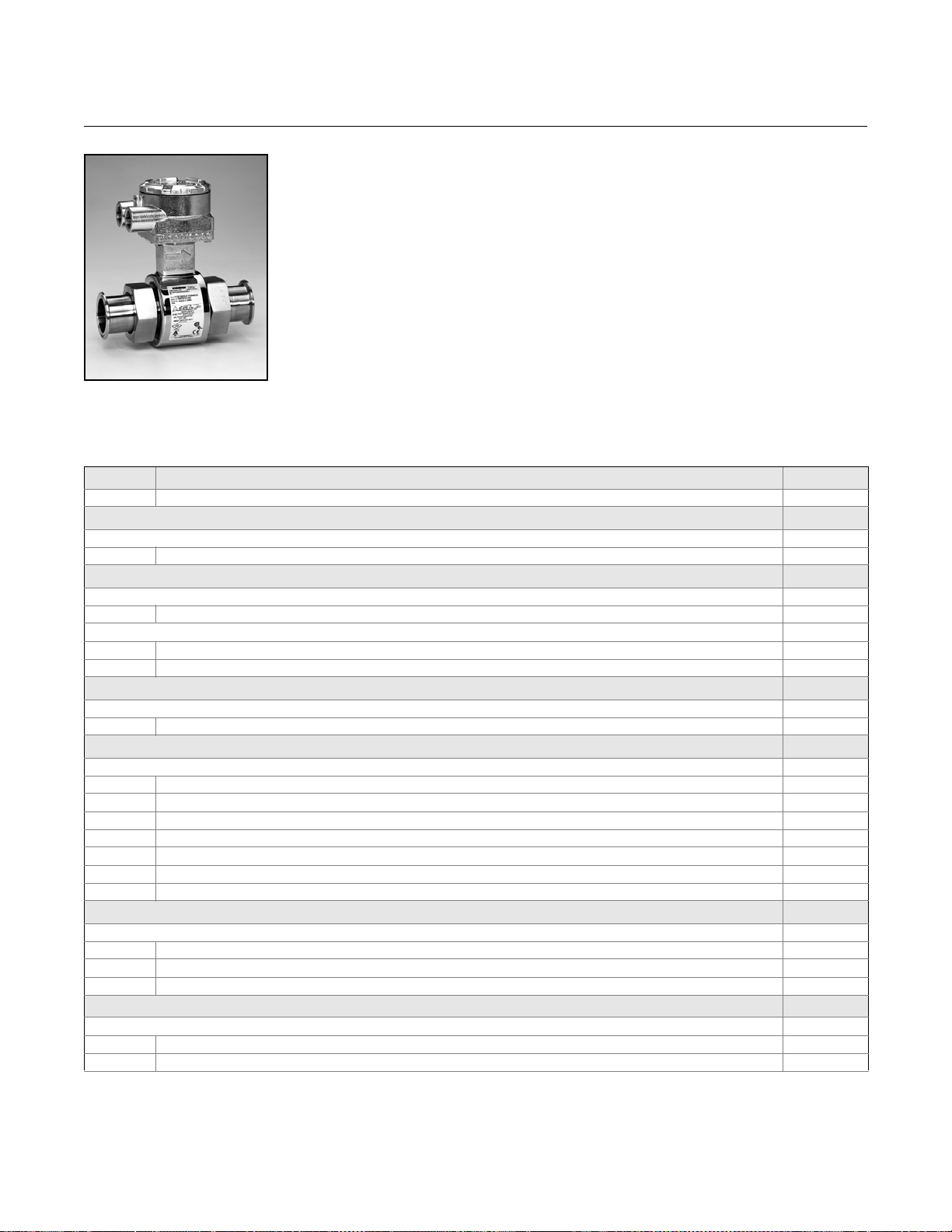
Reference Manual
00809-0100-4727, Rev EA
Rosemount 8700 Series
October 2010
Rosemount 8721 Hygienic Sensors
The 8721 hygienic sensor is specifically designed for the demanding applications in
food, beverage, and life sciences. The robust, all-welded, full diameter sensor is
constructed of FDA approved materials and is authorized to display the 3-A Symbol
(Authorization #1222), is certified by EHEDG (#C03-5229), and is approved for use in
FDA Grade A milk meter based timing loops (M-b 350). Sizes range from
(15mm) to 4-in. (100mm) and are available in a variety of industry standard process
connections.
Table 8. Rosemount 8721 Ordering Information
★ The Standard offering represents the most common options. The starred options (★) should be selected for best delivery.
__The Expanded offering is subject to additional delivery lead time.
Model Product Description
8721 Hygienic Magnetic Flowmeter Sensor
Lining Material
Standard Standard
A PFA ★
Electrode Material
Standard Standard
S 316L SST (standard) ★
Expanded
H Nickel Alloy 276 (UNS N10276)
P 80% Platinum-20% Iridium
Electrode Construction
Standard Standard
A Standard measurement electrodes ★
Line Sizes
Standard Standard
005 15 mm (1/2 in.) ★
010 25 mm (1 in.) ★
015 40 mm (11/2 in.) ★
020 50 mm (2.0 in.) ★
025 65 mm (21/2 in.) ★
030 80 mm (3.0 in.) ★
040 100 mm (4.0 in.) ★
Transmitter Mounting Configuration
Standard Standard
R Remote, for use with 8712, or remote version of 8732 transmitter ★
U Integral, mounted to 8732 transmitter ★
X Sensor only (does not include terminal junction box) ★
Process Connection Type
Standard Standard
A Tri-Clamp
B IDF Sanitary screw type
(1)
(2)
1
/2-in.
★
★
A-46
Page 91

Reference Manual
00809-0100-4727, Rev EA
October 2010
Table 8. Rosemount 8721 Ordering Information
★ The Standard offering represents the most common options. The starred options (★) should be selected for best delivery.
__The Expanded offering is subject to additional delivery lead time.
Expanded
C ANSI Weld Nipple
D DIN 11851 (Imperial)
E DIN 11851 (Metric)
F DIN 11864-1 form A
G DIN 11864-2 form A
H SMS Connection
J Cherry-Burrell I-Line
K DIN 11850 Weld Nipple
Process Gasket Material
Standard Standard
1 Silicone gasket seal ★
2 EPDM ★
Expanded
4 Viton
8 EPDM Compression - limiting
9 Viton Compression - limiting
X No gasket (User supplied; only applicable with Process Connection B)
Product Certifications
Standard Standard
NA CE Marked, No Approvals ★
N0 Factory Mutual (FM) Ordinary Location; CSA; CE Marking; 3-A; EHEDG Type EL
(2)
(3)
(3)
Rosemount 8700 Series
(3)
★
Options (Include with selected model number)
Expanded
AH Electropolished process connection surface finish < 15 in. Ra (0.38 m Ra)
D1 High Accuracy Calibration [0.25% of rate from 3-30 ft/s (0.9-10 m/s)] matched sensor and transmitter system
D3 High Velocity Meter Verification. Calibration verified at 1, 3, 10, and 20 ft./sec (0.3., 1, 3, and 6 m/s)
HD DanFoss Lay Length
HP Process Data PD340 (Alfa-Laval PD340) 250 mm lay length and Tri-Clamp process connections
J1 CM20 Conduit Adapter (Applies to Transmitter Mount Option “R” only)
J2 PG13.5 Conduit Adapter (Applies to Transmitter Mount Option “R” only)
Q4 Calibration Certificate per ISO 10474 3.1B
Q8 Material Traceability Certificate per ISO 10474 3.1B (product contact surfaces)
SJ 304 Stainless Steel terminal junction box (Remote configuration only)
Typical Model Number: 8721 A S A 020 U A 1 N0
(1) Tri-Clamp specification per BPE-2002
(2) IDF Specification per BS4825 Part 4
(3) EHEDG Document 8 requires mechanical compression limiting, provided by Compression - limiting gaskets for line sizes 1- 4-in. only.
A-47
Page 92

Reference Manual
00809-0100-4727, Rev EA
Rosemount 8700 Series
October 2010
Taggi ng The sensor and transmitter will be tagged, at no charge, in accordance with
customer requirements.
Transmitter tag character height is 0.125 in. (3.18 mm). Sensor tag: 40
character maximum.
Transmitter tag: see Configuration Data Sheet for character maximum.
Ordering Procedure To order, select the desired sensor and/or transmitter by specifying model
codes from the ordering table.
For remote transmitter applications, note the cable specification
requirements.
Sensors and transmitters must be selected from Product Data Sheet
00813-0100-4727.
Standard Configuration Unless the Configuration Data Sheet is completed, the transmitter will be
shipped as follows:
Engineering Units: ft/sec
4 mA (1 Vdc): 0
20 mA (5 Vdc): 30
Sensor Size: 3-in.
Empty Pipe: Off
Sensor Calibration Number: 1000005010000000
Cable Requirements for
Remote Transmitters
Integrally Mounted Rosemount 8732E Transmitters are factory configured
with the attached sensor size and appropriate calibration number.
Description Length P/N
Signal Cable (20 AWG)
Belden 8762, Alpha 2411
equivalent
Coil Drive Cable
(14 AWG) Belden 8720,
Alpha 2442 equivalent
Combination Signal and
Coil Drive Cable
(18 AWG)
(1) Combination signal and coil drive cable is not recommended for
high-signal magmeter system. For remote mount installations,
combination signal and coil drive cable should be limited to less
than 330 ft (100 m).
(1)
ft
m
ft
m
ft
m
08712-0061-0001
08712-0061-2003
08712-0060-0001
08712-0060-2003
08712-0752-0001
08712-0752-2003
Remote transmitter installations require equal lengths of signal and coil drive
cables. Integrally mounted transmitters are factory wired and do not require
interconnecting cables.
Lengths from 5 to 1,000 ft. (1.5 to 300 m) may be specified, and will be
shipped with the sensor. Cable longer than 100 ft. (30 m) is not re commended
for high-signal s yst em s.
A-48
Page 93

Reference Manual
00809-0100-4727, Rev EA
October 2010
Appendix B Approvals
Approved Manufacturing Locations . . . . . . . . . . . . . . . . . page B-1
European Directive Information . . . . . . . . . . . . . . . . . . . . page B-1
Hazardous Locations Product Approvals Offering . . . . . page B-3
Hazardous Location Certifications . . . . . . . . . . . . . . . . . . page B-7
Rosemount 8700 Series
APPROVED MANUFACTURING LOCATIONS
EUROPEAN DIRECTIVE INFORMATION
Rosemount Inc. — Eden Prairie, Minnesota, USA
Fisher-Rosemount Technologias de Flujo, S.A. de C.V. —
Chihuahua Mexico
Emerson Process Management Flow — Ede, The Netherlands
Asia Flow Technologies Center — Nanjing, China
The EC declaration of conformity for all applicable European directives for this product can be
found on our website at www.rosemount.com. A hard copy may be obtained by contacting your
local sales office.
ATEX Directive Rosemount Inc. complies with the ATEX Directive.
Type n protection type in accordance with EN50 021
• Closing of entries in the device must be carried out using the appropriate EEx e or EEx n
metal cable gland and metal blanking plug or any appropriate ATEX approved cable gland
and blanking plug with IP66 rating certified by an EU approved certification body.
For Rosemount 8732E transmitters:
Complies with Essential Health and Safety Requirements:
EN 60079-0: 2006
EN 60079-1: 2007
EN 60079-7: 2007
EN 60079-11: 2007
EN 60079-15: 2005
EN 61241-0: 2004
EN 61241-1: 2006
For Rosemount 8712E transmitters:
European Pressure
Equipment Directive
(PED) (97/23/EC)
www.rosemount.com
Complies with Essential Health and Safety Requirements:
EN 60079-15: 2003
For Rosemount 8700 Series Sensors:
Complies with Essential Health and Safety Requirements:
EN 61241-0: 2006
EN 61241-1: 2004
Rosemount 8705 and 8707 Magnetic Flowmeter sensors in line size and flange
combinations:
Line Size: 11/2 in. - 24 in. with all DIN flanges and ANSI 150 and
ANSI 300 flanges. Also available with ANSI 600 flanges in limited line sizes.
Line Size: 30 in. - 36 in. with AWWA 125 flanges
QS Certificate of Assessment - EC No. PED-H-100
Module H Conformity Assessment
Page 94

Rosemount 8700 Series
Rosemount 8711 Magnetic Flowmeter Sensors
Line Sizes: 1.5, 2, 3, 4, 6, and 8 in.
QS Certificate of Assessment - EC No. PED-H-100
Module H Conformity Assessment
Rosemount 8721 Sanitary Magmeter Sensors
in line sizes of 11/2 in. and larger:
Module A Conformity Assessment
All other Rosemount 8705/8707/8711/8721
Sensors —
in line sizes of 1 in. and less:
Sound Engineering Practice
Sensors that are SEP are outside the scope of PED and cannot be marked for compliance with
PED.
Mandatory CE-marking for sensors in accordance with Article 15 of the PED can be found on the
sensor body (CE 0575).
Sensor category I is assessed for conformity per module A procedures.
Sensor categories II – III, use module H for conformity assessment procedures.
Reference Manual
00809-0100-4727, Rev EA
October 2010
Electro Magnetic
Compatibility (EMC)
(2004/108/EC)
Low Voltage Directive
Model 8732E, 8712E, and 8712D EN 61326: 2006
Installed signal wiring should not be run together and should not be in the same cable tray as AC
power wiring.
Device must be properly grounded or earthed according to local electric codes.
Rosemount combination cable model number
08712-0752-0001 (ft.) or 08712-0752-0003 (m) is required to be used to meet EMC
requirements.
Model 8732E, 8712E, and 8712D - EN 61010 -1: 2001
(2006/95/EC)
Other important
guidelines
Only use new, original parts.
To prevent the process medium escaping, do not unscrew or remove process flange bolts,
adapter bolts or bleed screws during operation.
Maintenance shall only be done by qualified personnel.
CE Marking
Compliance with all applicable European Union Directives. (Note: CE Marking is not
available on Rosemount 8712H).
IECEx Certificates C-Tick Marking
Rosemount Inc. complies with the following IEC Requirements.
For Rosemount 8732E transmitters:
IEC 60079-0: 2004
IEC 60079-0: 2007
IEC 60079-1: 2007
IEC 60079-11: 2006
IEC 60079-15: 2005
IEC 60079-7: 2006
IEC 61241-0: 2004
IEC 61241-1: 2004
B-2
For Rosemount 8712E transmitters:
IEC 60079-0: 2004
IEC 60079-15: 2005-03
Page 95

Reference Manual
00809-0100-4727, Rev EA
October 2010
Rosemount 8700 Series
HAZARDOUS LOCATIONS PRODUCT APPROVALS OFFERING
The Rosemount 8700 Series Magnetic Flowmeters offer many different
hazardous locations certifications. The table below provides an overview of
the available hazardous area approval options. Equivalent hazardous
locations certifications for sensor and transmitter must match in integrally
mounted magnetic flowmeter systems. Remote mounted magnetic flowmeter
systems do not require matched hazardous location certifications. For
complete information about the hazardous area approval codes listed, see
Hazardous Location Certifications starting on page B-7.
Table B-1. Factory Mutual (FM) Approvals Offering
Transmitter 8732E 8712E
Sensor 8705 8707 8711 8705 8707 8711 8707
Hazardous Area Approval Code
Non-Classified Locations
Transmitter NA NA NA NA NA NA N0
Sensor NA N0 NA NA N0 NA N0
Suitable for Class I, Division 1
Explosion-Proof
Trans: Groups C, D T6 E5
Sensor: Groups C, D T6 E5
(2)
(2)
- E5 - - - -
- E5 - - - -
Explosion-Proof with Intrinsically Safe Output
Trans: Groups C, D T6 E5
Sensor: Groups C, D T6 E5
(2)(3)
(2)
- E5
- E5 - - - -
(3)
- - - -
Suitable for Class I, Division 2
Non-Flammable Fluids
Trans: Groups A,B,C,D T4 N0 N0 N0 N0 N0 N0 N0
Sensor: Groups A,B,C,D
N0 N0
(4)
N0 N0 N0
T5
Flammable Fluids
Trans: Groups A,B,C,D T4 N5 N5 N5 N5 N5 N5 N5
Sensor: Groups A,B,C,D
N5 N5
(4)
N5 N5 N5
T5
Non-Flammable Fluids with Intrinsically Safe Output
Trans: Groups A,B,C,D T4 N0
Sensor: Groups A,B,C,D
(3)
N0 N0
N0
(3)
(4)
(3)
N0
- - - -
N0 - - - -
T5
Other Certifications Product Certification Code
Canadian Registration
CR CR Standard CR CR Standard CR
Number (CRN)
European Pressure
PD - PD PD - PD Equipment Directive
(PED)
NSF 61 Drinking Water
(1) Remote Transmitte r Only.
(2) Available in line sizes 0.5-in. to 8-in. (15 mm to 200 mm) only.
(3) For I.S. Output, Output Code B or F must be ordered.
(4) 8707 Sensor has Temp Code - T3C.
(5) Product Certification Codes are added to the Sensor model number only.
(6) Only available with PTFE or Polyurethane Lining Material and 316L SST Electrodes.
(6)
DW - DW DW - DW -
(1)
(4)
(4)
(5)
N0 N0
N5 N5
8712H
(1)
(4)
(4)
B-3
Page 96

Reference Manual
00809-0100-4727, Rev EA
Rosemount 8700 Series
Table B-2. Canadian Standards Association (CSA) Approvals Offering
Transmitter 8732E 8712E
Sensor 8705 8707 8711 8705 8707 8711 8707
Hazardous Area Approval Code
Non-Classified Locations
Transmitter NA - NA NA - NA -
Sensor NA - NA NA - NA -
Suitable for Class I, Division 2
Non-Flammable Fluids
Trans: Groups A,B,C,D T4 N0 N0 N0 N0 N0 N0 N0
Sensor: Groups A,B,C,D
N0 N0
(2)
N0 N0 N0
T5
Other Certifications Product Certification Code
Canadian Registration
CR CR Standard CR CR Standard CR
Number (CRN)
European Pressure
PD - PD PD - PD Equipment Directive
(PED)
NSF 61 Drinking Water
(1) Remote Transmitte r Only.
(2) 8707 Sensor has Temp Code - T3C.
(3) Product Certification Codes are added to the Sensor model number only.
(4) Only available with PTFE or Polyurethane Lining Material and 316L SST Electrodes.
(4)
DW - DW DW - DW -
(1)
(2)
(3)
N0 N0
October 2010
8712H
(1)
(2)
B-4
Page 97

Reference Manual
00809-0100-4727, Rev EA
October 2010
Table B-3. ATEX Approvals Offering
Transmitter 8732E 8712E
Sensor 8705 8711 8705 8711
Hazardous Area Approval Code
Non-Hazardous
Trans: LVD and EMC NA NA NA NA
Sensor: LVD and EMC NA NA NA NA
Equipment Category 2
Gas Group IIB
Trans: Ex d IIB T6 ED ED - -
Sensor: Ex e ia IIC T3...T6 KD
Gas Group IIC
Trans: Ex d IIC T6 E1 E1 - -
Sensor: Ex e ia IIC T3...T6 E1 E1 - -
Gas Group IIB with Intrinsically Safe Output
Trans: Ex de [ia] IIB T6 ED
Sensor: Ex e ia IIC T3...T6 KD
Gas Group IIC with Intrinsically Safe Output
Trans: Ex de [ia] IIC T6 E1
Sensor: Ex e ia IIC T3...T6 E1 E1 - -
Equipment Category 3
Gas Group IIC
Trans: Ex nA nL IIC T4 N1 N1 N1 N1
Sensor: Ex nA [L] IIC
T3...T6
Equipment Category 1 - Dust Environment
Dust Environment Only
Trans: Dust Ignition Proof ND ND - -
Sensor: Dust Ignition Proof ND ND - -
Other Certifications Product Certification Code
Canadian Registration
Number (CRN)
European Pressure
Equipment Directive (PED)
NSF 61 Drinking Water
(1) Remote Transmitte r Only.
(2) With integral mount transmitter, approval is valid for Gas Group IIB.
(3) For I.S. Output, Output Code B or F must be ordered.
(4) Product Certification Codes are added to the Sensor model number only.
(5) Only available with PTFE or Polyurethane Lining Material and 316L SST Electrodes.
(5)
(2)
(3)
(2)
(3)
KD
ED
KD
E1
(2)
(3)
(2)
(3)
N1 N1 N1 N1
CR Standard CR Standard
PD PD PD PD
DW DW DW DW
Rosemount 8700 Series
(1)
- -
- -
- -
- -
(4)
B-5
Page 98

Reference Manual
00809-0100-4727, Rev EA
Rosemount 8700 Series
Table B-4. IECEx Approvals Offering
Transmitter 8732E
Sensor 8705 8711 8705 8711
Hazardous Area Approval Code
Non-Hazardous
Trans: Low Voltage and EMC NA NA NA NA
Sensor: Low Voltage and EMC NA NA NA NA
Suitable for Zone 1
Gas Group IIB
Trans: Ex d IIB T6 EF EF
Gas Group IIC
Trans: Ex d IIC T6 E7 E7
Gas Group IIB with Intrinsically Safe Output
Trans: Ex de [ia] IIB T6 EF
(2)
Gas Group IIC with Intrinsically Safe Output
Trans: Ex de [ia] IIC T6 E1
(3)
Suitable for Zone 2
Gas Group IIC
Trans: Ex nA nL IIC T4 N7 N7 N7 N7
Suitable for Zone 20
Dust Environment Only
Trans: Dust Ignition Proof NF NF
Other Certifications Product Certification Code
Canadian Registration Number (CRN) CR Standard CR Standard
European Pressure Equipment Directive (PED) PD PD PD PD
NSF 61 Drinking Water
(1) Available in remote mount configuration only. Requires equivalent ATEX approval on the sensor.
(2) For I.S. Output, Output Code B or F must be ordered.
(3) Product Certification Codes are added to the Sensor model number only.
(4) Product Certification Codes are added to the Sensor model number only.
(5) Only available with PTFE or Polyurethane Lining Material and 316L SST Electrodes.
(5)
DW DW DW DW
(1)
(3)
EF
(3)
E1
(3)
Product Certification Code
October 2010
8712E
(4)
B-6
Page 99

Reference Manual
00809-0100-4727, Rev EA
October 2010
Rosemount 8700 Series
HAZARDOUS LOCATION CERTIFICATIONS
North American
Certifications
Equivalent Hazardous Location Certifications for sensor and transmitter must match in
integrally-mounted magnetic flowmeter systems. Remote-mounted systems do not require
matched hazardous location certification option codes.
Factory Mutual (FM)
N0 Division 2 Approval for
Non-Flammable Fluids (All Sensors)
Class I, Division 2, Groups A, B, C, D
Temp Code – T5 (8705/8711 at 60 °C)
Temp Code – T3C (8707 at 60 °C)
Dust-Ignition proof Class II/III, Division 1, Groups E, F, G
Temp Code – T6 (8705/8711 at 60 °C)
Temp Code – T3C (8707 at 60 °C)
Enclosure Type 4X
N0 for 8721 Hygienic Sensor
Factory Mutual (FM) Ordinary Location;
CE Marking; 3-A Symbol Authorization #1222;
EHEDG Type EL
N5 Division 2 Approval for Flammable Fluids
(All Sensors)
Class I, Division 2, Groups A, B, C, D
Temp Code – T5 (8705/8711 at 60 °C)
Temp Code – T3C (8707 at 60 °C)
Dust-Ignition proof Class II/III, Division 1, Groups E, F, G
Temp Code – T6 (8705/8711 at 60 °C)
Temp Code – T3C (8707 at 60 °C)
Enclosure Type 4X
E5 Explosion-Proof (8705 and 8711 Only)
Explosion-Proof for Class I, Division 1, Groups C, D
Temp Code – T6 at 60 °C
Dust-Ignition proof Class II/III, Division 1, Groups E, F, G
Temp Code – T6 at 60 °C
Class I, Division 2, Groups A, B, C, D
Temp Code – T5 at 60 °C
Enclosure Type 4X
Canadian Standards
Association (CSA)
N0 Suitable for Class I, Division 2, Groups A, B, C, D
Temp Code – T5 (8705/8711 at 60 °C)
Temp Code – T3C (8707 at 60 °C)
Dust-Ignition proof Class II/III, Division 1, Groups E, F, G
Enclosure Type 4X
N0 for 8721 Hygienic Sensor
Canadian Standards Association (CSA) Ordinary Location;
CE Marking; 3-A Symbol Authorization #1222;
EHEDG Type EL
European Certifications ND ATEX Dust Certificate No.: KEMA 06ATEX0006
II 1D Ex tD A20 IP6x T105°C (-50 ≤ T
0575
INSTALLATION INSTRUCTIONS
The cable and conduit entry devices and blanking elements shall be of a certified IP6x type,
suitable for the conditions of use and correctly installed. At maximum ambient temperatures or at
process temperatures above 60 °C heat resistant cables with a temperature rating of at least 90
°C shall be used.
amb
≤ 65 °C)
B-7
Page 100

Rosemount 8700 Series
N1 ATEX Non-Sparking/Non-incendive
Certificate No: KEMA02ATEX1302X II 3G
EEx nA [L] IIC T3... T6
Ambient Temperature Limits -20 to 65 °C
SPECIAL CONDITIONS FOR SAFE USE (X):
The relation between ambient temperature, process temperature, and temperature class is to be
taken from Table B-7. The electrical data is to be taken from the summary in Table B-5.
E1, ATEX Increased Safety with IS Electrodes
KD Certificate No: KEMA03ATEX2052X II 1/2G
EEx e ia IIC T3... T6 (Ta = -20 to +60°)
V
SPECIAL CONDITIONS FOR SAFE USE (X):
The relation between ambient temperature, process temperature, and temperature class is to be
taken from Table B-6. The electrical data is to be taken from the summary in Table B-5.
INSTALLATION INSTRUCTIONS:
At ambient temperature above 50 °C, the flowmeter shall be used with heat resistant cables with
a temperature rating of at least 90 °C.
A fuse with a rating of maximum 0,7 A according to IEC 60127-1 shall be included in the coil
excitation circuit if the sensors are used with other flow transmitters (e.g. Rosemount 8712).
0575
max
Reference Manual
00809-0100-4727, Rev EA
October 2010
= 40 V
International
Certifications
IECEX
NF IECEx Dust
Certificate Number: IECEx KEM 09.0078
Ex tD A20 IP6x T105 °C (-50 ≤ T
INSTALLATION INSTRUCTIONS:
The cable and conduit entry devices and blanking elements shall be of a certified IP6x type,
suitable for the conditions of use and correctly installed. At maximum ambient temperatures or at
process temperatures above 60 °C heat, resistant cables with a temperature rating of at least 90
°C shall be used.
amb
≤ 65 °C)
NEPSI - China
E3, NEPSI Increased Safety with IS Electrodes
EP Certificate No: GYJ071438X
Ex e ia IIC T3... T6 (Ta = -20 to +60°)
= 40 V
V
max
InMetro - Brazil
E2, InMetro Increased Safety with IS Electrodes
EB Certificate No: NCC 5030/08
BR-Ex e ia IIC T3... T6 (Ta = -20 to +60°)
= 40 V
V
max
KOSHA - Korea
E9, KOSHA Increased Safety with IS Electrodes
EK Certificate No: 2005-2233-Q1X
Ex e ia IIC T3... T6 (Ta = -20 to +60°)
= 40 V
V
max
B-8
 Loading...