

Reference manual
00809-0400-4444, Rev AB
December 2017
Rosemount® 8732EM Transmitter with Modbus
Protocol Reference Manual


Contents
Contents
Chapter 1 Safety messages ............................................................................................................ 1
Chapter 2 Introduction .................................................................................................................. 5
2.1 System description ...................................................................................................................... 5
2.2 Product recycling/disposal ...........................................................................................................7
Chapter 3 Sensor Installation ......................................................................................................... 9
3.1 Handling and Lifting Safety ..........................................................................................................9
3.2 Location and Position ................................................................................................................ 10
3.3 Sensor Installation ..................................................................................................................... 12
3.4 Process reference connection ....................................................................................................20
Chapter 4 Remote Transmitter Installation .................................................................................. 25
4.1 Pre-installation .......................................................................................................................... 25
4.2 Transmitter symbols ..................................................................................................................28
4.3 Mounting .................................................................................................................................. 28
4.4 Wiring ....................................................................................................................................... 29
Chapter 5 Basic configuration ...................................................................................................... 43
5.1 Cover jam screw ........................................................................................................................ 43
5.2 Basic setup ................................................................................................................................ 43
5.3 Modbus configuration ............................................................................................................... 47
5.4 Local operator interface (LOI) .................................................................................................... 48
Chapter 6 Advanced installation details ....................................................................................... 49
6.1 Hardware switches .................................................................................................................... 49
6.2 Additional loops ........................................................................................................................ 51
6.3 Coil housing configuration .........................................................................................................59
Chapter 7 Operation .................................................................................................................... 67
7.1 Introduction .............................................................................................................................. 67
7.2 Local operator interface (LOI) .................................................................................................... 67
Chapter 8 Advanced Configuration Functionality ......................................................................... 77
8.1 Introduction .............................................................................................................................. 77
8.2 Configure outputs ..................................................................................................................... 77
8.3 Configure LOI ............................................................................................................................ 98
8.4 Additional parameters .............................................................................................................100
8.5 Configure special units ............................................................................................................ 102
Chapter 9 Advanced Diagnostics Configuration ..........................................................................107
9.1 Introduction ............................................................................................................................ 107
9.2 Modbus communication diagnostics .......................................................................................108
9.3 Licensing and enabling ............................................................................................................ 110
9.4 Tunable empty pipe detection .................................................................................................110
9.5 Electronics temperature .......................................................................................................... 112
9.6 Ground/wiring fault detection ................................................................................................. 113
9.7 High process noise detection ...................................................................................................114
9.8 Coated electrode detection .....................................................................................................115
9.9 SMART™ Meter Verification ......................................................................................................117
9.10 Run manual SMART Meter Verification .................................................................................... 121
Reference manual i

Contents
9.11 Continuous SMART Meter Verification .....................................................................................123
9.12 SMART Meter Verification test results ......................................................................................125
9.13 SMART Meter Verification measurements ............................................................................... 126
9.14 Optimizing the SMART Meter Verification ............................................................................... 128
Chapter 10 Digital Signal Processing ............................................................................................ 131
10.1 Introduction ............................................................................................................................ 131
10.2 Safety messages ......................................................................................................................131
10.3 Process noise profiles .............................................................................................................. 132
10.4 High process noise diagnostic ..................................................................................................133
10.5 Optimizing flow reading in noisy applications ..........................................................................133
10.6 Explanation of signal processing algorithm ..............................................................................137
Chapter 11 Maintenance ..............................................................................................................139
11.1 Introduction ............................................................................................................................ 139
11.2 Safety information ...................................................................................................................139
11.3 Installing a Local Operator Interface (LOI) ................................................................................ 140
11.4 Replacing 8732EM electronics stack ........................................................................................ 141
11.5 Replacing a socket module/terminal block .............................................................................. 143
11.6 Trims ....................................................................................................................................... 147
11.7 Review .....................................................................................................................................149
Chapter 12 Troubleshooting ........................................................................................................ 151
12.1 Introduction ............................................................................................................................ 151
12.2 Safety information ...................................................................................................................152
12.3 Installation check and guide .................................................................................................... 152
12.4 Diagnostic messages ...............................................................................................................154
12.5 Basic troubleshooting ..............................................................................................................164
12.6 Sensor troubleshooting ........................................................................................................... 167
12.7 Installed sensor tests ............................................................................................................... 169
12.8 Uninstalled sensor tests ...........................................................................................................171
12.9 Technical support ....................................................................................................................174
12.10 Service .....................................................................................................................................175
Appendices and reference
Appendix A Product Specifications ................................................................................................177
A.1 Rosemount 8700M Flowmeter Platform specifications ........................................................... 177
A.2 Transmitter specifications ....................................................................................................... 182
A.3 8705-M Flanged Sensor Specifications .....................................................................................191
A.4 8711-M/L Wafer Sensor Specifications .....................................................................................196
A.5 8721 Hygienic (Sanitary) Sensor Specifications ........................................................................199
Appendix B Product Certifications ................................................................................................ 205
Appendix C Mobus Coil and Register Map ..................................................................................... 207
Appendix D Wiring Diagrams ........................................................................................................223
D.1 Wiring sensor to transmitter ....................................................................................................224
Appendix E Implementing a Universal Transmitter ....................................................................... 227
E.1 Safety messages ...................................................................................................................... 227
E.2 Universal capability ..................................................................................................................228
E.3 Three step process ...................................................................................................................228
E.4 Wiring the universal transmitter .............................................................................................. 229
ii Rosemount® 8732EM Transmitter with Modbus Protocol Reference Manual

Contents
E.5 Rosemount sensors ................................................................................................................. 229
E.6 Brooks sensors .........................................................................................................................233
E.7 Endress and Hauser sensors ..................................................................................................... 235
E.8 Fischer and Porter sensors ....................................................................................................... 236
E.9 Foxboro sensors ...................................................................................................................... 243
E.10 Kent Veriflux VTC sensor ..........................................................................................................247
E.11 Kent sensors ............................................................................................................................ 249
E.12 Krohne sensors ........................................................................................................................ 250
E.13 Taylor sensors ..........................................................................................................................251
E.14 Yamatake Honeywell sensors .................................................................................................. 253
E.15 Yokogawa sensors ................................................................................................................... 254
E.16 Generic manufacturer sensor to 8732 Transmitter .................................................................. 256
Reference manual iii

Contents
iv Rosemount® 8732EM Transmitter with Modbus Protocol Reference Manual

1 Safety messages
WARNING!
General hazards. Failure to follow these instructions could result in death or serious injury.
• Read this manual before working with the product. For personal and system safety, and
for optimum product performance, make sure you thoroughly understand the contents
before installing, using, or maintaining this product.
• Installation and servicing instructions are for use by qualified personnel only. Do not
perform any servicing other than that contained in the operating instructions, unless
qualified.
• Verify the installation is completed safely and is consistent with the operating
environment.
• Do not substitute factory components with non-factory compenents. Substitution of
components may impair Intrinsic Safety.
• Do not perform any services other than those contained in this manual.
• Process leaks may result in death or serious injury.
• Mishandling products exposed to a hazardous substance may result in death or serious
injury.
• The electrode compartment may contain line pressure; it must be depressurized before
the cover is removed.
• If the product being returned was exposed to a hazardous substance as defined by
OSHA, a copy of the required Material Safety Data Sheet (MSDS) for each hazardous
substance identified must be included with the returned goods.
• The products described in this document are NOT designed for nuclear-qualified
applications. Using non-nuclear qualified products in applications that require nuclearqualified hardware or products may cause inaccurate readings. For information on
Rosemount nuclear-qualified products, contact your local Emerson Process
Management Sales Representative.
Safety messages
Reference manual 1

Safety messages
WARNING!
Explosion hazards. Failure to follow these instructions could cause an explosion, resulting in
death or serious injury.
• If installed in explosive atmospheres [hazardous areas, classified areas, or an “Ex”
environment], it must be assured that the device certification and installation
techniques are suitable for that particular environment.
• Do not remove transmitter covers in explosive atmospheres when the circuit is live.
Both transmitter covers must be fully engaged to meet explosion-proof requirements.
• Do not disconnect equipment when a flammable or combustible atmosphere is present.
• Do not connect a Rosemount transmitter to a non-Rosemount sensor that is located in
an explosive atmosphere. The transmitter has not been evaluated for use with other
manufacturers' magnetic flowmeter sensors in hazardous (Ex or Classified) areas.
Special care should be taken by the end-user and installer to ensure the transmitter
meets the safety and performance requirements of the other manufacturer’s
equipment.
• Follow national, local, and plant standards to properly earth ground the transmitter and
sensor. The earth ground must be separate from the process reference ground.
• Rosemount Magnetic Flowmeters ordered with non-standard paint options or non-
metallic labels may be subject to electrostatic discharge. To avoid electrostatic charge
build-up, do not rub the flowmeter with a dry cloth or clean with solvents.
WARNING!
Electrical hazards. Failure to follow these instructions could cause damaging and unsafe
discharge of electricity, resulting in death or serious injury.
• Follow national, local, and plant standards to properly earth ground the transmitter and
sensor. The earth ground must be separate from the process reference ground.
• Disconnect power before servicing circuits.
• Allow ten minutes for charge to dissipate prior to removing electronics compartment
cover. The electronics may store energy in this period immediately after power is
removed.
• Avoid contact with leads and terminals. High voltage that may be present on leads could
cause electrical shock.
• Rosemount Magnetic Flowmeters ordered with non-standard paint options or non-
metallic labels may be subject to electrostatic discharge. To avoid electrostatic charge
build-up, do not rub the flowmeter with a dry cloth or clean with solvents.
2 Rosemount® 8732EM Transmitter with Modbus Protocol Reference Manual

Safety messages
NOTICE
Damage hazards. Failure to follow these instructions could resulting damage or destruction of
equipment.
• The sensor liner is vulnerable to handling damage. Never place anything through the
sensor for the purpose of lifting or gaining leverage. Liner damage may render the
sensor inoperable.
• Metallic or spiral-wound gaskets should not be used as they will damage the liner face of
the sensor. If spiral wound or metallic gaskets are required for the application, lining
protectors must be used. If frequent removal is anticipated, take precautions to protect
the liner ends. Short spool pieces attached to the sensor ends are often used for
protection.
• Correct flange bolt tightening is crucial for proper sensor operation and life. All bolts
must be tightened in the proper sequence to the specified torque specifications. Failure
to observe these instructions could result in severe damage to the sensor lining and
possible sensor replacement.
• In cases where high voltage/high current are present near the meter installation, ensure
proper protection methods are followed to prevent stray electricity from passing
through the meter. Failure to adequately protect the meter could result in damage to
the transmitter and lead to meter failure.
• Completely remove all electrical connections from both sensor and transmitter prior to
welding on the pipe. For maximum protection of the sensor, consider removing it from
the pipeline.
• Do not connect mains or line power to the magnetic flowtube sensor or to the
transmitter coil excitation circuit.
Reference manual 3

Safety messages
4 Rosemount® 8732EM Transmitter with Modbus Protocol Reference Manual

2 Introduction
Topics covered in this chapter:
System description
•
Product recycling/disposal
•
2.1 System description
The 8700M Magnetic Flowmeter Platform consists of a sensor and a transmitter. The
sensor is installed in-line with the process piping; the transmitter can be integrally
mounted or remotely mounted to the sensor.
Intergral field mount transmitterFigure 2-1:
Introduction
Remote field mount transmitterFigure 2-2:
There are three Rosemount® flow sensors available.
(1) Also available for use with 8707 High Signal sensor with dual calibration (option code D2).
Reference manual 5
(1)

Introduction
8705 flanged sensorFigure 2-3:
8711 wafer sensorFigure 2-4:
8721 hygienic sensorFigure 2-5:
The flow sensor contains two magnetic coils located on opposite sides of the sensor. Two
electrodes, located perpendicular to the coils and opposite each other, make contact with
the liquid. The transmitter energizes the coils and creates a magnetic field. A conductive
liquid moving through the magnetic field generates an induced voltage at the electrodes.
This voltage is proportional to the flow velocity. The transmitter converts the voltage
detected by the electrodes into a flow reading. A cross-sectional view is show in Figure 2-6.
6 Rosemount® 8732EM Transmitter with Modbus Protocol Reference Manual

8705 Cross SectionFigure 2-6:
2.2 Product recycling/disposal
Recycling of equipment and packaging should be taken into consideration and disposed of
in accordance with local and national legislation/regulations.
Introduction
Reference manual 7

Introduction
8 Rosemount® 8732EM Transmitter with Modbus Protocol Reference Manual

3 Sensor Installation
Topics covered in this chapter:
Handling and Lifting Safety
•
Location and Position
•
Sensor Installation
•
Process reference connection
•
This chapter provides instructions for handling and installing the flow sensor with or
without an integrally mounted transmitter.
Related information
Remote Transmitter Installation
Sensor Installation
3.1 Handling and Lifting Safety
CAUTION!
To reduce the risk of personal injury or damage to equipment, follow all lifting and handling
instructions.
• Handle all parts carefully to prevent damage. Whenever possible, transport the system
to the installation site in the original shipping container.
• PTFE-lined sensors are shipped with end covers that protect it from both mechanical
damage and normal unrestrained distortion. Remove the end covers just before
installation.
• Keep the shipping plugs in the conduit ports until you are ready to connect and seal
them. Appropriate care should be taken to prevent water ingress.
• The sensor should be supported by the pipeline. Pipe supports are recommended on
both the inlet and outlet sides of the sensor pipeline. There should be no additional
support attached to the sensor.
• Use proper PPE (Personal Protection Equipment) including safety glasses and steel toed
shoes.
• Do not lift the meter by holding the electronics housing or junction box.
• The sensor liner is vulnerable to handling damage. Never place anything through the
sensor for the purpose of lifting or gaining leverage. Liner damage can render the sensor
useless.
• Do not drop the device from any height.
Reference manual 9
Sensor Installation
3.2 Location and Position
3.2.1 Environmental considerations
To ensure maximum transmitter life, avoid extreme temperatures and excessive vibration.
Typical problem areas include the following:
• High-vibration lines with integrally mounted transmitters
• Tropical/desert installations in direct sunlight
• Outdoor installations in arctic climates
Remote mounted transmitters may be installed in the control room to protect the
electronics from the harsh environment and to provide easy access for configuration or
service.
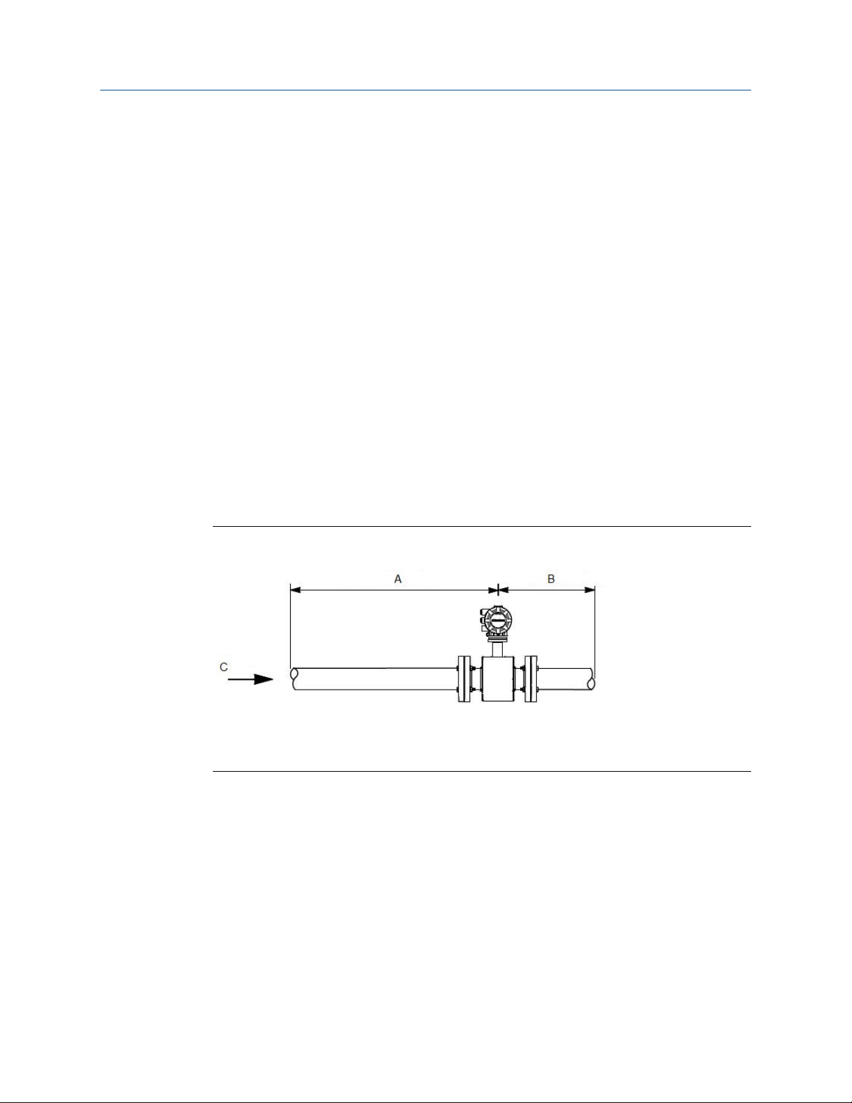
3.2.2 Upstream and downstream piping
To ensure specified accuracy over widely varying process conditions, install the sensor with
a minimum of five straight pipe diameters upstream and two pipe diameters downstream
from the electrode plane.
3.2.3
Upstream and downstream straight pipe diametersFigure 3-1:
A. Five pipe diameters (upstream)
B. Two pipe diameters (downstream)
C. Flow direction
Installations with reduced upstream and downstream straight runs are possible. In
reduced straight run installations, the meter may not meet absolute accuracy
specifications. Reported flow rates will still be highly repeatable.
Flow direction
The sensor should be mounted so that the arrow points in the direction of flow.
10 Rosemount® 8732EM Transmitter with Modbus Protocol Reference Manual
Flow direction arrowFigure 3-2:
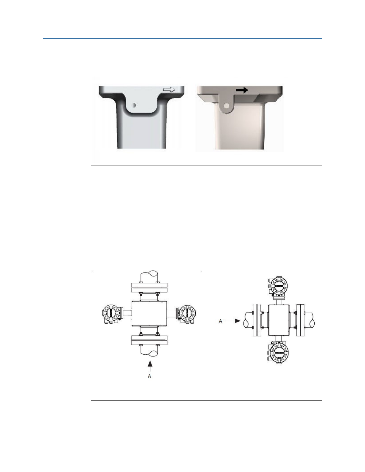
3.2.4 Sensor piping location and orientation
The sensor should be installed in a location that ensures it remains full during operation.
Depending on where it is installed, orientation must also be considered.
• Vertical installation with upward process fluid flow keeps the cross-sectional area
full, regardless of flow rate.
• Horizontal installation should be restricted to low piping sections that are normally
full.
Sensor Installation
Sensor orientationFigure 3-3:
A. Flow direction
Reference manual 11
Sensor Installation
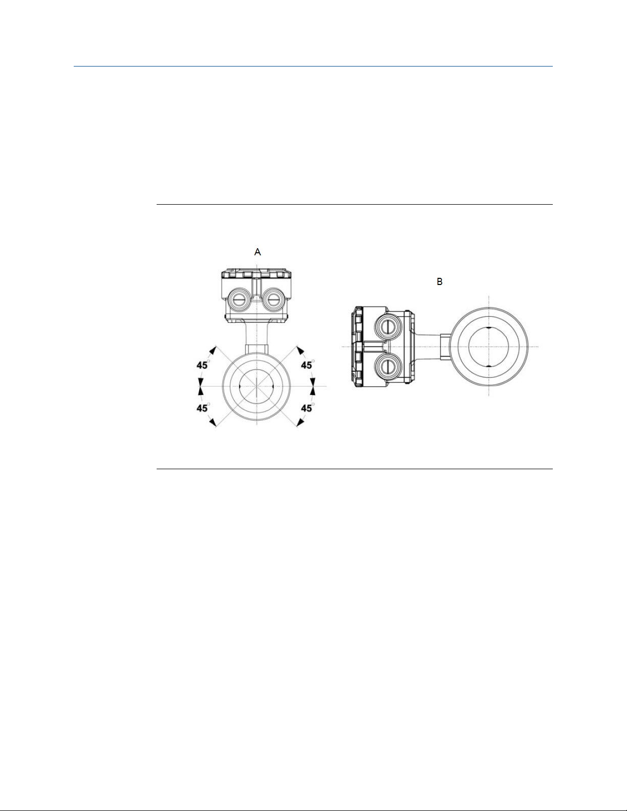
3.2.5 Electrode orientation
The electrodes in the sensor are properly oriented when the two measurement electrodes
are in the 3 and 9 o’clock positions or within 45 degrees from the horizontal, as shown on
the left side of Figure 3-4. Avoid any mounting orientation that positions the top of the
sensor at 90 degrees from the vertical position as shown on the right of the Electrode
Orientation figure.
Electrode orientationFigure 3-4:
A. Correct orientation
B. Incorrect orientation
The sensor may require a specific orientation to comply with Hazardous Area T-code
rating. Refer to the approrpirate reference manual for any potential restrictions.
3.3
Sensor Installation
3.3.1 Flanged sensors
Gaskets
The sensor requires a gasket at each process connection. The gasket material must be
compatible with the process fluid and operating conditions. Gaskets are required on each
side of a grounding ring (see Figure 3-5). All other applications (including sensors with
lining protectors or a grounding electrode) require only one gasket on each process
connection.
12 Rosemount® 8732EM Transmitter with Modbus Protocol Reference Manual
Sensor Installation
Note
Metallic or spiral-wound gaskets should not be used as they will damage the liner face of the sensor.
If spiral wound or metallic gaskets are required for the application, lining protectors must be used.
Gasket placement for flanged sensorsFigure 3-5:
A. Grounding ring and gasket (optional)
B. Customer-supplied gasket
Bolts
Note
Do not bolt one side at a time. Tighten both sides simultaneously. Example:
1. Snug upstream
2. Snug downstream
3. Tighten upstream
4. Tighten downstream
Do not snug and tighten the upstream side and then snug and tighten the downstream side. Failure
to alternate between the upstream and downstream flanges when tightening bolts may result in
liner damage.
Suggested torque values by sensor line size and liner type are listed in Table 3-2 for ASME
B16.5 flanges and Table 3-3 or Table 3-4 for EN flanges. Consult the factory if the flange
rating of the sensor is not listed. Tighten flange bolts on the upstream side of the sensor in
the incremental sequence shown in Figure 3-6 to 20% of the suggested torque values.
Repeat the process on the downstream side of the sensor. For sensors with greater or
fewer flange bolts, tighten the bolts in a similar crosswise sequence. Repeat this entire
tightening sequence at 40%, 60%, 80%, and 100% of the suggested torque values.
Reference manual 13
Sensor Installation
If leakage occurs at the suggested torque values, the bolts can be tightened in additional
10% increments until the joint stops leaking, or until the measured torque value reaches
the maximum torque value of the bolts. Practical consideration for the integrity of the liner
often leads to distinct torque values to stop leakage due to the unique combinations of
flanges, bolts, gaskets, and sensor liner material.
Check for leaks at the flanges after tightening the bolts. Failure to use the correct
tightening methods can result in severe damage. While under pressure, sensor materials
may deform over time and require a second tightening 24 hours after the initial
installation.
Flange bolt torquing sequenceFigure 3-6:
Prior to installation, identify the lining material of the flow sensor to ensure the suggested
torque values are applied.
Lining materialTable 3-1:
Fluoropolymer liners Other liners
T - PTFE P - Polyurethane
F - ETFE N - Neoprene
A - PFA L - Linatex (Natural Rubber)
K - PFA+ D - Adiprene
Suggested flange bolt torque values for Rosemount 8705 (ASME)Table 3-2:
Fluoropolymer liners Other liners
Size
Code Line Size
005 0.5-in. (15 mm) 8 8 N/A N /A
010 1-in. (25 mm) 8 12 6 10
015 1.5-in. (40 mm) 13 25 7 18
020 2-in. (50 mm) 19 17 14 11
Class 150
(pound-feet)
Class 300
(pound-feet)
Class 150
(pound-feet)
Class 300
(pound feet)
14 Rosemount® 8732EM Transmitter with Modbus Protocol Reference Manual

Sensor Installation
Table 3-2:
(continued)
Size
Code Line Size
025 2.5-in. (65 mm) 22 24 17 16
030 3-in. (80 mm) 34 35 23 23
040 4-in. (100 mm) 26 50 17 32
050 5-in. (125 mm) 36 60 25 35
060 6-in. (150 mm) 45 50 30 37
080 8-in. (200 mm) 60 82 42 55
100 10-in. (250 mm) 55 80 40 70
120 12-in. (300 mm) 65 125 55 105
140 14-in. (350 mm) 85 110 70 95
160 16-in. (400 mm) 85 160 65 140
180 18-in. (450 mm) 120 170 95 150
200 20-in. (500 mm) 110 175 90 150
240 24-in. (600 mm) 165 280 140 250
300 30-in. (750 mm) 195 415 165 375
360 36-in. (900 mm) 280 575 245 525
Suggested flange bolt torque values for Rosemount 8705 (ASME)
Fluoropolymer liners Other liners
Class 150
(pound-feet)
Class 300
(pound-feet)
Class 150
(pound-feet)
Class 300
(pound feet)
Table 3-3:
Suggested flange bolt torque values for Rosemount 8705 sensors with
fluoropolymer liners (EN 1092-1)
Size
code Line size
005 0.5-in. (15 mm) N/A N/A N/A 10
010 1-in. (25 mm) N/A N/A N/A 20
015 1.5-in. (40 mm) N/A N/A N/A 50
020 2-in. (50 mm) N/A N/A N/A 60
025 2.5-in. (65 mm) N/A N/A N/A 50
030 3-in. (80 mm) N/A N/A N/A 50
040 4-in. (100 mm) N/A 50 N/A 70
050 5.0-in. (125 mm) N/A 70 N/A 100
060 6-in. (150mm) N/A 90 N/A 130
080 8-in. (200 mm) 130 90 130 170
100 10-in. (250 mm) 100 130 190 250
120 12-in. (300 mm) 120 170 190 270
Fluoropolymer liners (in Newton-meters)
PN 10 PN 16 PN 25 PN 40
Reference manual 15

Sensor Installation
Table 3-3:
Suggested flange bolt torque values for Rosemount 8705 sensors with
fluoropolymer liners (EN 1092-1) (continued)
Size
code Line size
140 14-in. (350 mm) 160 220 320 410
160 16-in. (400 mm) 220 280 410 610
180 18-in. (450 mm) 190 340 330 420
200 20-in. (500 mm) 230 380 440 520
240 24-in. (600 mm) 290 570 590 850
Table 3-4:
Suggested flange bolt torque values for Rosemount 8705 sensors with
Fluoropolymer liners (in Newton-meters)
PN 10 PN 16 PN 25 PN 40
non-fluoropolymer liners (EN 1092-1)
Size
Code Line Size
005 0.5-in. (15 mm) N/A N/A N/A 20
010 1-in. (25 mm) N/A N/A N/A 30
015 1.5-in. (40 mm) N/A N/A N/A 40
020 2-in. (50 mm) N/A N/A N/A 30
025 2.5-in. (65 mm) N/A N/A N/A 35
030 3-in. (80 mm) N/A N/A N/A 30
040 4-in. (100 mm) N/A 40 N/A 50
050 5.0-in. (125 mm) N/A 50 N/A 70
060 6-in. (150mm) N/A 60 N/A 90
080 8-in. (200 mm) 90 60 90 110
100 10-in. (250 mm) 70 80 130 170
120 12-in. (300 mm) 80 110 130 180
140 14-in. (350 mm) 110 150 210 288
160 16-in. (400 mm) 150 190 280 410
180 18-in. (450 mm) 130 230 220 280
200 20-in. (500 mm) 150 260 300 350
240 24-in. (600 mm) 200 380 390 560
Non-fluoropolymer liners (in Newton-meters)
PN 10 PN 16 PN 25 PN 40
3.3.2 Wafer sensors
When installing wafer sensors, there are several components that must be included and
requirements that must be met.
16 Rosemount® 8732EM Transmitter with Modbus Protocol Reference Manual
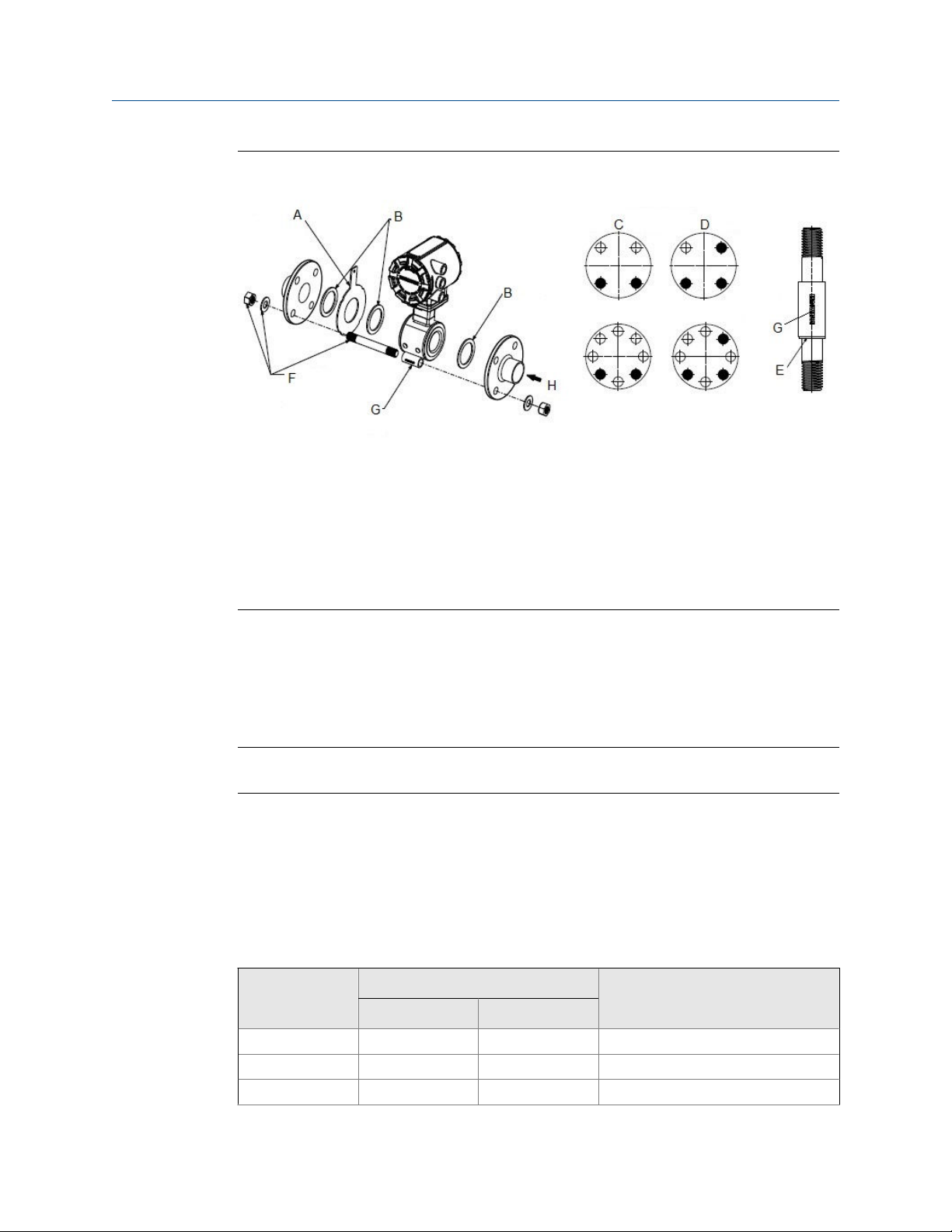
Wafer sensors installation components and assembly requirementsFigure 3-7:
A. Ground ring (optional)
B. Customer supplied gaskets
C. Spacer installation (horizontal meters)
D. Spacer installation (vertical meters)
E. O-ring
F. Installation studs, nuts, and washers (optional)
G. Wafer alignment spacer
H. Flow
Sensor Installation
Gaskets
The sensor requires a gasket at each process connection. The gasket material selected
must be compatible with the process fluid and operating conditions. Gaskets are required
on each side of a grounding ring. See Figure 3-7.
Note
Metallic or spiral-wound gaskets should not be used as they will damage the liner face of the sensor.
Alignment spacers
On 1.5 inch through 8 inch (40 through 200 mm) line sizes, Rosemount requires installing
the alignment spacers to ensure proper centering of the wafer sensor between the process
flanges. To order an Alignment Spacer Kit (quantity 3 spacers) use p/n 08711-3211-xxxx
where xxxx equals the dash number shown in Table 3-5.
Rosemount alignment spacersTable 3-5:
Line size
Dash-no. (-xxxx)
0A15 1.5 40 JIS 10K-20K
0A20 2 50 JIS 10K-20K
0A30 3 80 JIS 10K
Flange rating(in) (mm)
Reference manual 17

Sensor Installation
Rosemount alignment spacers (continued)Table 3-5:
Line size
Dash-no. (-xxxx)
0B15 1.5 40 JIS 40K
AA15 1.5 40 ASME- 150#
AA20 2 50 ASME - 150#
AA30 3 80 ASME - 150#
AA40 4 100 ASME - 150#
AA60 6 150 ASME - 150#
AA80 8 200 ASME - 150#
AB15 1.5 40 ASME - 300#
AB20 2 50 ASME - 300#
AB30 3 80 ASME - 300#
AB40 4 100 ASME - 300#
AB60 6 150 ASME - 300#
AB80 8 200 ASME - 300#
DB40 4 100 EN 1092-1 - PN10/16
DB60 6 150 EN 1092-1 - PN10/16
DB80 8 200 EN 1092-1 - PN10/16
DC80 8 200 EN 1092-1 - PN25
DD15 1.5 40 EN 1092-1 - PN10/16/25/40
DD20 2 50 EN 1092-1 - PN10/16/25/40
DD30 3 80 EN 1092-1 - PN10/16/25/40
DD40 4 100 EN 1092-1 - PN25/40
DD60 6 150 EN 1092-1 - PN25/40
DD80 8 200 EN 1092-1 - PN40
RA80 8 200 AS40871-PN16
RC20 2 50 AS40871-PN21/35
RC30 3 80 AS40871-PN21/35
RC40 4 100 AS40871-PN21/35
RC60 6 150 AS40871-PN21/35
RC80 8 200 AS40871-PN21/35
Flange rating(in) (mm)
Studs
Wafer sensors require threaded studs. See Figure 3-8 for torque sequence. Always check for
leaks at the flanges after tightening the flange bolts. All sensors require a second
tightening 24 hours after initial flange bolt tightening.
18 Rosemount® 8732EM Transmitter with Modbus Protocol Reference Manual
Sensor Installation
Stud specificationsTable 3-6:
Nominal sensor size Stud specifications
0.15–1-in. (4–25 mm) 316 SST ASTM A193, Grade B8M, Class 1 threaded mounted studs
1½–8-in. (40–200 mm) CS, ASTM A193, Grade B7, threaded mounting
studs
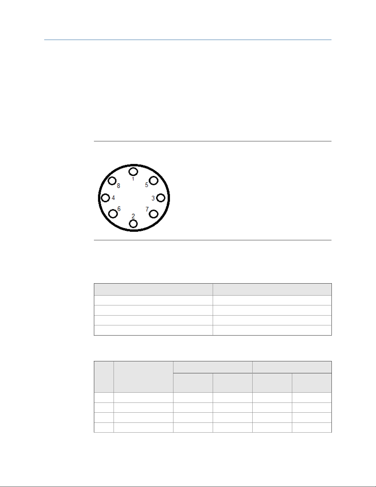
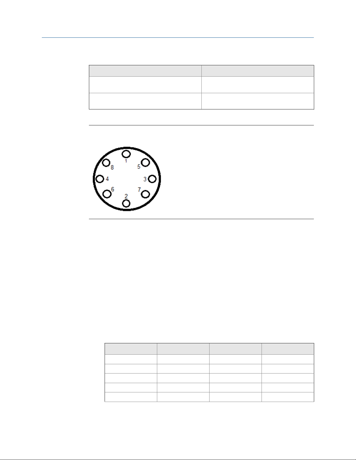
Flange bolt torquing sequenceFigure 3-8:
Installation
1. Insert studs for the the bottom side of the sensor between the pipe flanges and
center the alignment spacer in the middle of the stud. See Figure 3-7 for the bolt
hole locations recommended for the spacers provided. Stud specifications are listed
in Table 3-6.
2. Place the sensor between the flanges. Make sure the alignment spacers are properly
centered on the studs. For vertical flow installations slide the o-ring over the stud to
keep the spacer in place. See Figure 3-7. Ensure the spacers match the flange size
and class rating for the process flanges. See Table 3-5.
3. Insert the remaining studs, washers, and nuts.
4. Tighten to the torque specifications shown in Table 3-7. Do not over-tighten the
bolts or the liner may be damaged.
Rosemount 8711 torque specificationsTable 3-7:
Size code Line size Pound-feet Newton-meter
015 1.5-in. (40 mm) 15 20
020 2-in. (50 mm) 25 34
030 3-in. (80 mm) 40 54
040 4-in. (100 mm) 30 41
060 6-in. (150 mm) 50 68
Reference manual 19
Sensor Installation
Rosemount 8711 torque specifications (continued)Table 3-7:
Size code Line size Pound-feet Newton-meter
080 8-in. (200 mm) 70 95
3.3.3 Sanitary senors
Gaskets
The sensor requires a gasket at each of its connections to adjacent devices or piping. The
gasket material selected must be compatible with the process fluid and operating
conditions.
Note
Gaskets are supplied between the IDF fitting and the process connection fitting, such as a Tri-Clamp
fitting, on all Rosemount 8721 Sanitary sensors except when the process connection fittings are not
supplied and the only connection type is an IDF fitting.
Alignment and bolting
Standard plant practices should be followed when installing a magmeter with sanitary
fittings. Unique torque values and bolting techniques are not required.
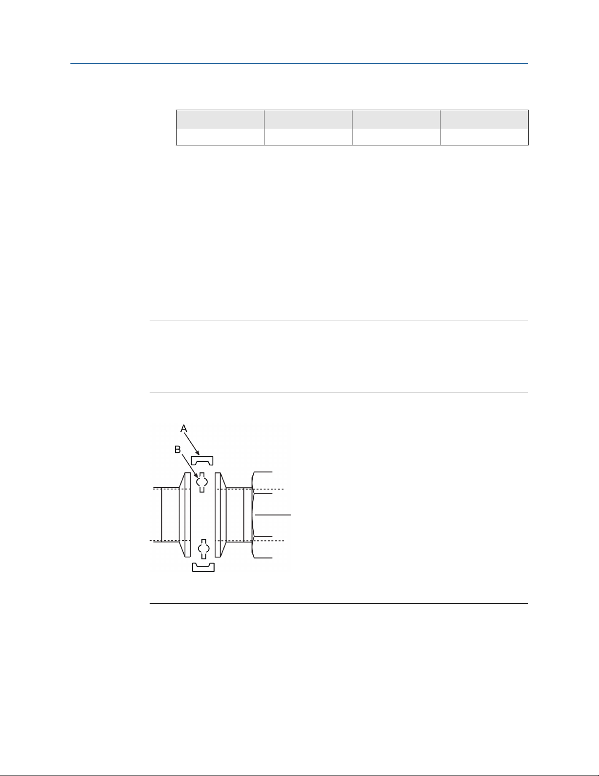
Sanitary sensor gasket and clamp alignmentFigure 3-9:
A. User supplied clamp
B. User supplied gasket
3.4
20 Rosemount® 8732EM Transmitter with Modbus Protocol Reference Manual
Process reference connection
The figures shown in this chapter illustrate process reference connections only. Earth
safety ground is also required as part of this installation, but is not shown in the figures.
Follow national, local, and plant electrical codes for safety ground.

Sensor Installation
Use the Process reference options table to determine which process reference option to
follow for proper installation.
Process reference optionsTable 3-8:
Grounding
Type of pipe
Conductive unlined pipe
Conductive lined
pipe
Non-conductive
pipe
Note
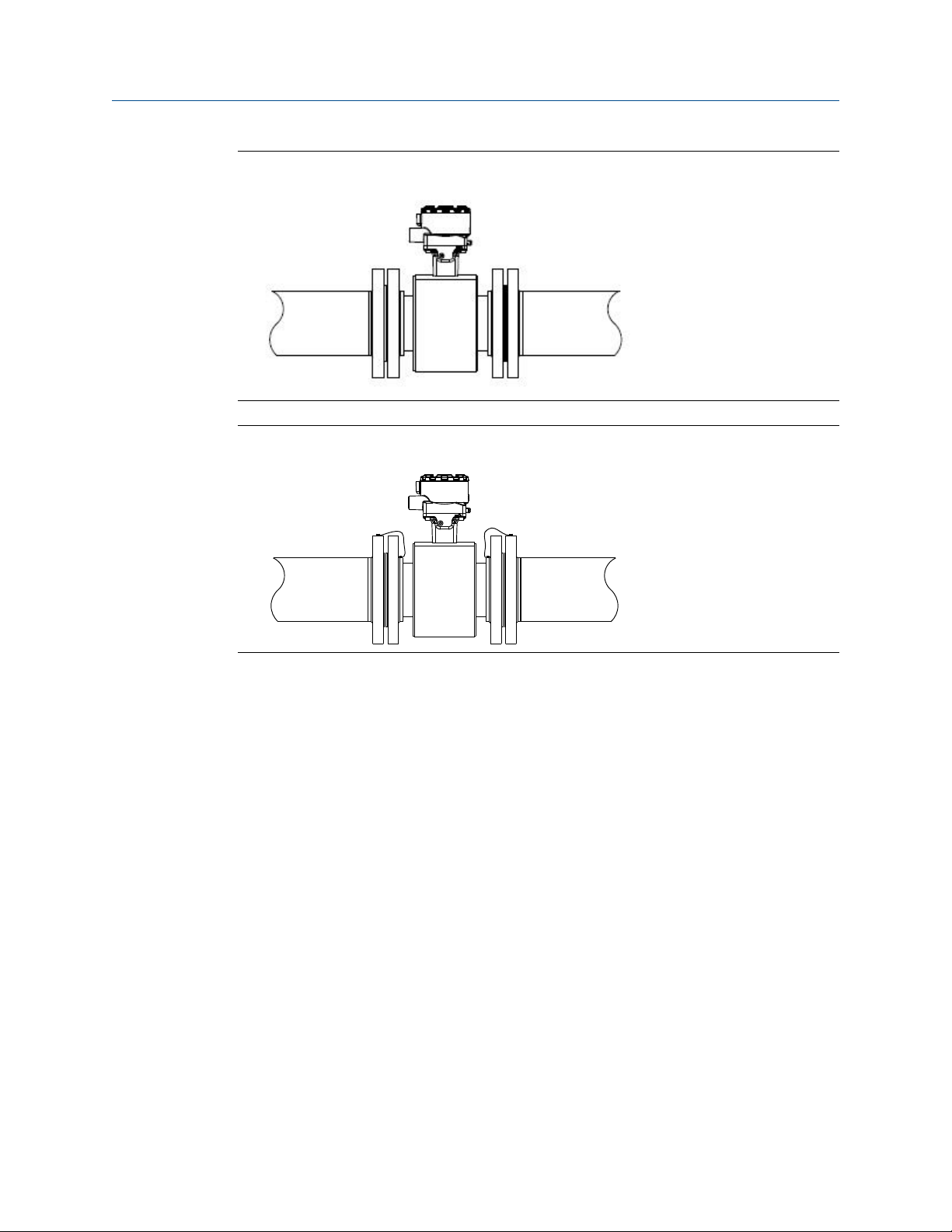
For line sizes 10-inch and larger the ground strap may come attached to the sensor body near the
flange. See Figure 3-14.
Figure 3-10:
straps Grounding rings
See Figure 3-10 See Figure 3-11 See Figure 3-13 See Figure 3-11
Insufficient
grounding
Insufficient
grounding
See Figure 3-11 See Figure 3-10 See Figure 3-11
See Figure 3-12 Not recommen-
Grounding straps in conductive unlined pipe or reference electrode in
Reference electrode
ded
Lining protectors
See Figure 3-12
lined pipe
Reference manual 21
Sensor Installation
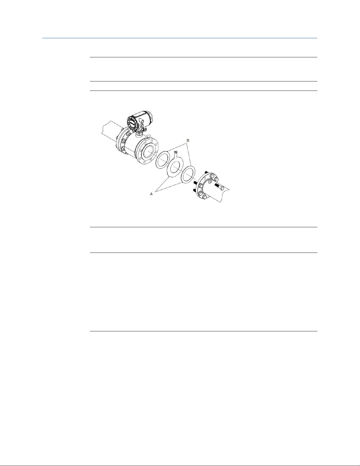
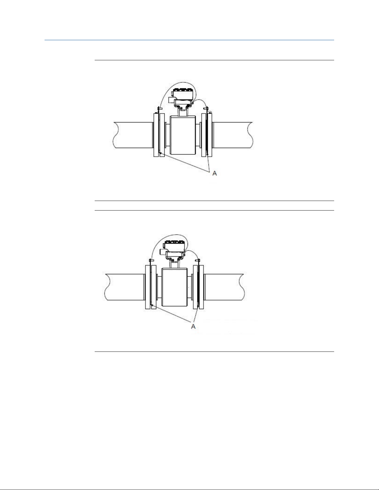
Grounding with grounding rings or lining protectors in conductive pipeFigure 3-11:
A. Grounding rings or lining protectors
Figure 3-12:
Grounding with grounding rings or lining protectors in non-conductive
pipe
A. Grounding rings or lining protectors
22 Rosemount® 8732EM Transmitter with Modbus Protocol Reference Manual
Sensor Installation
Grounding with reference electrode in conductive unlined pipeFigure 3-13:
Grounding for line sizes 10-in. and largerFigure 3-14:
Reference manual 23

Sensor Installation
24 Rosemount® 8732EM Transmitter with Modbus Protocol Reference Manual

Remote Transmitter Installation
4 Remote Transmitter Installation
Topics covered in this chapter:
Pre-installation
•
Transmitter symbols
•
Mounting
•
Wiring
•
This chapter provides instructions for installing and wiring a remotely mounted
transmitter.
Related information
Sensor Installation
4.1 Pre-installation
Before installing the transmitter, there are several pre-installation steps that should be
completed to make the installation process easier:
• Identify options and configurations that apply to your application
• Set the hardware switches if necessary
• Consider mechanical, electrical, and environmental requirements
Note
Refer to Appendix A for more detailed requirements.
Identify options and configurations
The typical transmitter installation includes a device power connection, a Modbus RS-485
output connection, and sensor coil and electrode connections. Other applications may
require one or more of the following configurations or options:
• Pulse output
• Discrete input/discrete output
Hardware switches
The transmitter has two user-selectable hardware switches. These switches set the
internal/external pulse power and transmitter security. The standard configuration for
these switches when shipped from the factory is as follows:
Reference manual 25

Remote Transmitter Installation
Setting Factory configuration
Internal/external pulse power External
Transmitter security Off
The internal/external pulse power switch is not available when ordered with intrinsically
safe output, ordering code B.
In most cases, it is not necessary to change the setting of the hardware switches. If the
switch settings need to be changed, refer to Section 6.1.
Be sure to identify any additional options and configurations that apply to the installation.
Keep a list of these options for consideration during the installation and configuration
procedures.
Mechanical considerations
The mounting site for the transmitter should provide enough room for secure mounting,
easy access to conduit entries, full opening of the transmitter covers, and easy readability
of the Local Operator Interface (LOI) screen (if equipped).
Hardware switch default settingsTable 4-1:
26 Rosemount® 8732EM Transmitter with Modbus Protocol Reference Manual

Rosemount 8732EM dimensional drawingFigure 4-1:
10.5
[130]
5.0
[128]
1.94
[49,0]
3.00
[76,2]
7.49
[190,0]
6.48
[164,6]
A
3.07
[78,0]
8.81
[224,0]
Remote Transmitter Installation
B
2.71
[76,2]
5.0
[128]
A
11.02
[280.0]
6.48
[164,6]
5.82
[148,0]
1.97
[50,0]
A. Conduit entry
2.71
[68,8]
½–14 NPT or M20
C
B. LOI cover
C. Mounting screws
Electrical considerations
Before making any electrical connections to the transmitter, consider national, local, and
plant electrical installation requirements. Be sure to have the proper power supply,
conduit, and other accessories necessary to comply with these standards.
The transmitter requires external power. Ensure access to a suitable power source.
Electrical dataTable 4-2:
Rosemount 8732EM Flow Transmitter
Power input AC power:
90–250VAC, 0.45A, 40VA
Standard DC power:
12–42VDC, 1.2A, 15W
Low power DC:
12–30VDC, 0.25A, 4W
Reference manual 27

Remote Transmitter Installation
Rosemount 8732EM Flow Transmitter
Pulsed circuit Internally powered (Active): Outputs up to
Modbus output circuit Internally powered (Active): Outputs up to
Termination resisters Typically 120 ohms. Refer to the MODBUS over
Um 250V
Coil excitation output 500mA, 40V max, 9W max
Environmental considerations
To ensure maximum transmitter life, avoid extreme temperatures and excessive vibration.
Typical problem areas include the following:
• High-vibration lines with integrally mounted transmitters
• Tropical or desert installations in direct sunlight
• Outdoor installations in arctic climates
Electrical data (continued)Table 4-2:
12VDC, 12.1mA, 73mW
Externally powered (Passive): Input up to
28VDC, 100mA, 1W
3.3VDC, 100mA, 100mW
Serial Line Specification & Implementation
Guide (http://www.modbus.org) for more details.
Remote mounted transmitters may be installed in the control room to protect the
electronics from the harsh environment and to provide easy access for configuration or
service.
4.2
Transmitter symbols
Caution symbol — check product documentation for details
Protective conductor (grounding) terminal
4.3 Mounting
Remote-mount transmitters are shipped wth a mounting bracket for use on a 2-in. pipe or
a flat surface.
28 Rosemount® 8732EM Transmitter with Modbus Protocol Reference Manual

Remote Transmitter Installation
Procedure
1. Orient the transmitter on the mounting bracket.
2. Attach the mounting bracket to the instrument pole and securely tighten the
fasteners.
Mounting bracketFigure 4-2:
C
A
B
D
A. U-bolt
B. Mounting bracket
C. Transmitter
D. Fasteners (example configuration)
3. To enable correct orientation, the LOI can be rotated in 90 degree increments up to
180 degrees. Do not rotate more than 180 degrees in any one direction.
4.4
Wiring
4.4.1 Conduit entries and connections
Transmitter conduit entry ports can be ordered with ½"-14NPT or M20 female threaded
connections. Conduit connections should be made in accordance with national, local, and
plant electrical codes. Unused conduit entries should be sealed with the appropriate
certified plugs. The plastic shipping plugs do not provide ingress protection.
4.4.2
Reference manual 29
Conduit requirements
• For installations with an intrinsically safe electrode circuit, a separate conduit for the
coil cable and the electrode cable may be required.
Remote Transmitter Installation
• For installations with non-intrinsically safe electrode circuit, or when using the
• Bundled cables from other equipment in a single conduit are likely to create
• Electrode cables should not be run together in the same cable tray with power
• Output cables should not be run together with power cables.
• Select conduit size appropriate to feed cables through to the flowmeter.
A
B
combination cable, a single dedicated conduit run for the coil drive and electrode
cable between the sensor and the remote transmitter may be acceptable. Removal
of the barriers for intrinsic safety isolation is permitted for non-intrinsically safe
electrode installations.
interference and noise in the system. See Figure 4-3.
cables.
Best practice conduit preparationFigure 4-3:
B
A. Power
B. Output
C. Coil
D. Electrode
E. Safety ground
E
E
C
D
E
30 Rosemount® 8732EM Transmitter with Modbus Protocol Reference Manual
4.4.3 Sensor to transmitter wiring
Integral mount transmitters
Integral mount transmitters ordered with a sensor will be shipped assembled and wired at
the factory using an interconnecting cable. Use only the factory supplied cable provided
with the instrument. For replacement transmitters use the existing interconnecting cable
from the original assembly. Replacement cables, if applicable, are available (see
Figure 4-4).
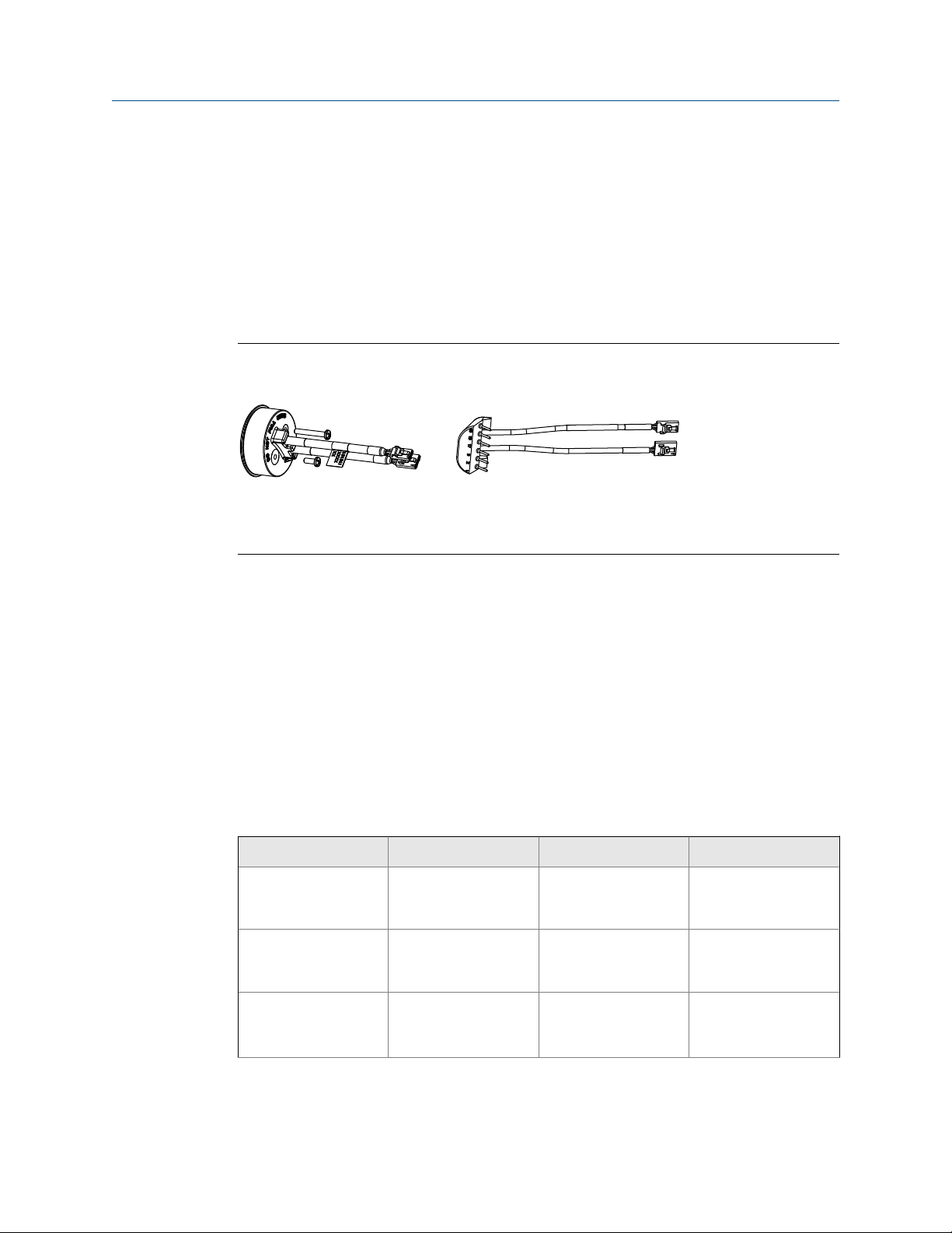
Replacement interconnecting cablesFigure 4-4:
Remote Transmitter Installation
A
A. Socket module 08732-CSKT-0001
B. IMS cable 08732-CSKT-0004
B
Remote mount transmitters
Cables kits are available as individual component cables or as a combination coil/electrode
cable. Remote cables can be ordered directly using the kit numbers shown in Table 4-3,
Table 4-4, and Table 4-5. Equivalent Alpha cable part numbers are also provided as an
alternative. To order cable, specify length as quantity desired. Equal length of component
cables is required.
Examples:
• 25 feet = Qty (25) 08732-0065-0001
• 25 meters = Qty (25) 08732-0065-0002
Component cable kits - standard temperature (-20°C to 75°C)Table 4-3:
Cable kit # Description Individual cable Alpha p/n
08732-0065-0001
(feet)
08732-0065-0002
(meters)
08732-0065-0003
(feet)
Kit, component cables,
Std temp (includes Coil
and Electrode)
Kit, component cables,
Std temp (includes Coil
and Electrode)
Kit, component cables,
Std temp (includes Coil
and I.S. Electrode)
Coil
Electrode
Coil
Electrode
Coil
Instrinsically Safe Blue
Electrode
2442C
2413C
2442C
2413C
2442C
Not available
Reference manual 31

Remote Transmitter Installation
Cable kit # Description Individual cable Alpha p/n
08732-0065-0004
(meters)
Cable kit # Description Individual cable Alpha p/n
08732-0065-1001
(feet)
08732-0065-1002
(meters)
08732-0065-1003
(feet)
08732-0065-1004
(meters)
Component cable kits - standard temperature (-20°C to 75°C) (continued)Table 4-3:
Kit, component cables,
Std temp (includes Coil
and I.S. Electrode)
Coil
Instrinsically Safe Blue
Electrode
2442C
Not available
Component cable kits - extended temperature (-50°C to 125°C)Table 4-4:
Kit, Component Cables, Ext Temp. (includes Coil and Electrode)
Kit, Component Cables, Ext Temp. (includes Coil and Electrode)
Kit, Component Cables, Ext Temp. (includes Coil and I.S.
Electrode)
Kit, Component Cables, Ext Temp. (includes Coil and I.S.
Electrode)
Coil
Electrode
Coil
Electrode
Coil
Intrinsically Safe Blue
Electrode
Coil
Intrinsically Safe Blue
Electrode
Not available
Not available
Not available
Not available
Not available
Not available
Not available
Not available
Combination cable kits - coil and electrode cable (-20°C to 80°C)Table 4-5:
Cable kit # Description
08732-0065-2001 (feet) Kit, Combination Cable, Standard
08732-0065-2002 (meters)
08732-0065-3001 (feet) Kit, Combination Cable, Submersible
08732-0065-3002 (meters)
(80°C dry/60°C Wet)
(33ft Continuous)
Cable requirements
Shielded twisted pairs or triads must be used. For installations using the individual coil
drive and electrode cable, see Figure 4-5. Cable lengths should be limited to less than 500
feet (152 m). Consult factory for length between 500–1000 feet (152–304 m). Equal
length cable is required for each. For installations using the combination coil drive/
electrode cable, see Figure 4-6. Combination cable lengths should be limited to less than
330 feet (100 m).
32 Rosemount® 8732EM Transmitter with Modbus Protocol Reference Manual

Individual component cablesFigure 4-5:
A B
Remote Transmitter Installation
1 2
3
3
D
C
E
F
A. Coil drive
B. Electrode
C. Twisted, stranded, insulated 14 AWG conductors
D. Drain
E. Overlapping foil shield
F. Outer jacket
G. Twisted, stranded, insulated 20 AWG conductors
• 1 = Red
• 2 = Blue
• 3 = Drain
• 17 = Black
• 18 = Yellow
• 19 = White
17 18 19
G
Reference manual 33

Remote Transmitter Installation
Combination coil and electrode cableFigure 4-6:
17
1
2
3
19
18
17
A
B
C
A. Electrode shield drain
B. Overlapping foil shield
C. Outer jacket
• 1 = Red
• 2 = Blue
• 3 = Drain
• 17 = Reference
• 18 = Yellow
• 19 = White
Cable preparation
Prepare the ends of the coil drive and electrode cables as shown in Figure 4-7. Remove only
enough insulation so that the exposed conductor fits completely under the terminal
connection. Best practice is to limit the unshielded length (D) of each conductor to less
than one inch. Excessive removal of insulation may result in an unwanted electrical short to
the transmitter housing or other terminal connections. Excessive unshielded length, or
failure to connect cable shields properly, may also expose the unit to electrical noise,
resulting in an unstable meter reading.
34 Rosemount® 8732EM Transmitter with Modbus Protocol Reference Manual

Remote Transmitter Installation
Cable endsFigure 4-7:
D
A
B
C
A. Coil
B. Electrode
C. Combination
D. Unshielded length
WARNING!
Shock hazard! Potential shock hazard across remote junction box terminals 1 and 2 (40V).
WARNING!
Explosion hazard! Electrodes exposed to process. Use only compatible transmitter and approved
installation practices. For process temperatures greater than 284°F (140°C), use a wire rated for
257°F (125°C).
Reference manual 35

Remote Transmitter Installation
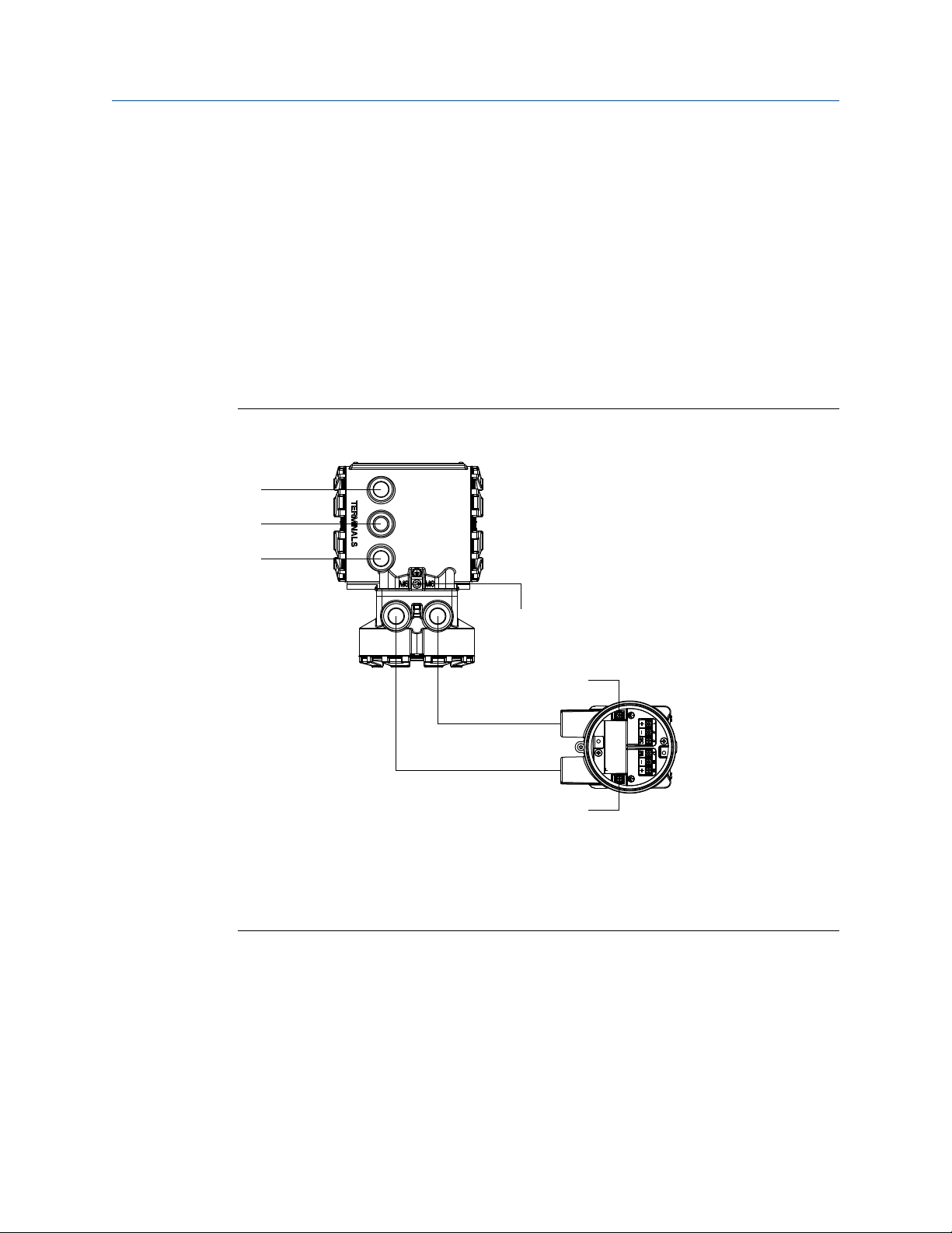
Remote junction box terminal blocks
Remote junction box viewsFigure 4-8:
A
A. Sensor
B. Transmitter
B
Sensor/transmitter wiringTable 4-6:
Wire color Sensor terminal Transmitter terminal
Red 1 1
Blue 2 2
Shield 3 or Float 3
Black 17 17
Yellow 18 18
White 19 19
4.4.4 Power and I/O terminal blocks
Remove the back cover of the transmitter to access the terminal block.
8732EM Terminal blocksFigure 4-9:
A
Modbus (B)
Modbus (A)
A. AC version
B. DC version
36 Rosemount® 8732EM Transmitter with Modbus Protocol Reference Manual
B
Modbus (B)
Modbus (A)

Remote Transmitter Installation
8732EM Power and I/O terminalsTable 4-7:
Terminal number AC version DC version
1 Modbus (B) Modbus (B)
2 Modbus (A) Modbus (A)
3 Pulse (–) Pulse (–)
4 Pulse (+) Pulse (+)
(1)
5
(1)
6
(1)
7
(1)
8
9 AC (Neutral)/L2 DC (–)
10 AC L1 DC (+)
(1) Only available with ordering code AX.
Discrete I/O 1 (–) Discrete I/O 1 (–)
Discrete I/O 1 (+) Discrete I/O 1 (+)
Discrete I/O 2 (–) Discrete I/O 2 (–)
Discrete I/O 2 (+) Discrete I/O 2 (+)
Reference manual 37

Remote Transmitter Installation
4.4.5 Powering the transmitter
The transmitter is available in three models. The AC powered transmitter is designed to be
powered by 90–250VAC (50/60Hz). The DC powered transmitter is designed to be
powered by 12–42VDC. The low power transmitter is designed to be powered by
12–30VDC. Before connecting power to the transmitter, be sure to have the proper power
supply, conduit, and other accessories. Wire the transmitter according to national, local,
and plant electrical requirements for the supply voltage.
If installing in a hazardous location, verify that the meter has the appropriate hazardous
area approval. Each meter has a hazardous area approval tag attached to the top of the
transmitter housing.
AC power supply requirements
Units powered by 90 - 250VAC have the following power requirements. Peak inrush is
35.7A at 250VAC supply, lasting approximately 1ms. Inrush for other supply voltages can
be estimated with: Inrush (Amps) = Supply (Volts) / 7.0
AC current requirementsFigure 4-10:
0.24
0.22
0.20
A
0.18
0.16
0.14
0.12
90
110 130 150 170B190 210 230 250
A. Supply current (amps)
B. Power supply (VAC)
38 Rosemount® 8732EM Transmitter with Modbus Protocol Reference Manual

Remote Transmitter Installation
Apparent powerFigure 4-11:
34
32
30
28
A
26
24
22
20
90
110 130 150 170B190 210 230 250
A. Apparent power (VA)
B. Power supply (VAC)
DC power supply requirements
Standard DC units powered by 12VDC power supply may draw up to 1.2A of current steady
state. Low power DC units may draw up to 0.25A of current steady state. Peak inrush is
42A at 42VDC supply, lasting approximately 1ms. Inrush for other supply voltages can be
estimated with: Inrush (Amps) = Supply (Volts) / 1.0
DC current requirementsFigure 4-12:
1.2
1.1
1.0
0.9
0.8
A
0.7
0.6
0.5
0.4
0.3
0.2
12
A. Supply current (amps)
B. Power supply (VDC)
17 22 27
B
32 37 42
Reference manual 39

Remote Transmitter Installation
0.25
0.2
0.15
A
0.1
0.05
0
A. Supply current (amps)
B. Power supply (VDC)
Supply wire requirements
Use 10–18 AWG wire rated for the proper temperature of the application. For wire 10–14
AWG use lugs or other appropriate connectors. For connections in ambient temperatures
above 122 °F (50 °C), use a wire rated for 194 °F (90 °C). For DC powered transmitters with
extended cable lengths, verify that there is a minimum of 12VDC at the terminals of the
transmitter with the device under load.
10
Low power DC current requirementsFigure 4-13:
15 20 25
B
30
Electrical disconnect requirements
Connect the device through an external disconnect or circuit breaker per national and local
electrical code.
Installation category
The installation category for the transmitter is OVERVOLTAGE CAT II.
Overcurrent protection
The transmitter requires overcurrent protection of the supply lines. Fuse rating and
compatible fuses are shown in Table 4-8.
Fuse requirementsTable 4-8:
Power system Power supply Fuse rating Manufacturer
AC power 90–250VAC 2 Amp quick acting Bussman AGC2 or
equivalent
DC power 12–42VDC 3 Amp quick acting Bussman AGC3 or
equivalent
DC low power 12–30VDC 3 Amp quick acting Bussman AGC3 or
equivalent
40 Rosemount® 8732EM Transmitter with Modbus Protocol Reference Manual

Remote Transmitter Installation
Power terminals
For AC powered transmitter (90–250VAC, 50/60 Hz):
• Connect AC Neutral to terminal 9 (AC N/L2) and AC Line to terminal 10 (AC/L1).
For DC powered transmitter:
• Connect negative to terminal 9 (DC -) and positive to terminal 10 (DC +).
• DC powered units may draw up to 1.2A.
Cover jam screw
For flow meters shipped with a cover jam screw, the screw should be installed after the
instrument has been wired and powered up. Follow these steps to install the cover jam
screw:
1. Verify the cover jam screw is completely threaded into the housing.
2. Install the housing cover and verify the cover is tight against the housing.
3. Using a 2.5 mm hex wrench, loosen the jam screw until it contacts the transmitter
cover.
4. Turn the jam screw an additional 1/2 turn counterclockwise to secure the cover.
Note
Application of excessive torque may strip the threads.
5. Verify the cover cannot be removed.
Reference manual 41

Remote Transmitter Installation
42 Rosemount® 8732EM Transmitter with Modbus Protocol Reference Manual

5 Basic configuration
Topics covered in this chapter:
Cover jam screw
•
Basic setup
•
Modbus configuration
•
Local operator interface (LOI)
•
Once the magnetic flowmeter is installed and power has been supplied, the transmitter
must be configured through the basic setup. These parameters can be configured through
either an LOI or a Modbus host. Configuration settings are saved in nonvolatile memory
within the transmitter. Descriptions of more advanced functions are included in Chapter 8.
5.1 Cover jam screw
Basic configuration
5.2
For flow meters shipped with a cover jam screw, the screw should be installed after the
instrument has been wired and powered up. Follow these steps to install the cover jam
screw:
Procedure
1. Verify the cover jam screw is completely threaded into the housing.
2. Install the housing cover and verify the cover is tight against the housing.
3. Using a 2.5 mm hex wrench, loosen the jam screw until it contacts the transmitter
cover.
4. Turn the jam screw an additional 1/2 turn counterclockwise to secure the cover.
Note
Application of excessive torque may strip the threads.
5. Verify the cover cannot be removed.
Basic setup
Tag (registers 68–71)
Tag is the quickest and shortest way of identifying and distinguishing between
transmitters. Transmitters can be tagged according to the requirements of your
application. The tag may be up to eight characters long.
Reference manual 43

Basic configuration
Flow units (register 61)
The flow units variable specifies the format in which the flow rate will be displayed. Units
should be selected to meet your particular metering needs.
Volume unitsTable 5-1:
Register value Units
241 Barrels (31 gal)/sec
242 Barrels (31 gal)/min
243 Barrels (31 gal)/hour
244 Barrels (31 gal)/day
132 Barrels (42 gal)/sec
133 Barrels (42 gal)/min
134 Barrels (42 gal)/hour
135 Barrels (42 gal)/day
248 Cubic cm/minute
26 Cubic feet/second
15 Cubic feet/minute
130 Cubic feet/hour
27 Cubic feet/day
28 Cubic meters/second
131 Cubic meters/minute
19 Cubic meters/hour
29 Cubic meters/day
22 Gallons/second
16 Gallons/minute
136 Gallons/hour
23 Millions gallons/day
235 Gallons/day
137 Imperial gallons/sec
18 Imperial gallons/min
30 Imperial gallons/hour
31 Imperial gallons/day
24 Liters/second
17 Liters/minute
138 Liters/hour
240 Liters/day
44 Rosemount® 8732EM Transmitter with Modbus Protocol Reference Manual

Mass unitsTable 5-2:
Register value Units
73 Kilograms/second
74 Kilograms/minute
75 Kilograms/hour
76 Kilograms/day
77 Metric ton/minute
78 Metric ton/hour
79 Metric ton/day
80 Pounds/second
81 Pounds/minute
82 Pounds/hour
83 Pounds/day
84 Short tons/minute
85 Short tons/hour
86 Short tons/day
Basic configuration
Other unitsTable 5-3:
Register value Units
20 Feet/second (default)
21 Meters/second
253 Special units (see Section 8.5)
Line size (register 65)
The line size (sensor size) must be set to match the actual sensor connected to the
transmitter.
Register value
0 0.10-in. (2 mm)
1 0.15-in. (4 mm)
2 0.25-in. (6 mm)
3 0.30-in. (8 mm)
4 0.50-in. (15 mm)
5 0.75-in. (18 mm)
6 1-in. (25 mm)
7 1.5-in. (40 mm)
8 2-in. (50 mm)
Line size
Reference manual 45

Basic configuration
Register value Line size
9 2.5-in. (65 mm)
10 3-in. (80 mm) (default)
11 4-in. (100 mm)
12 5-in. (125 mm)
13 6-in. (150 mm)
14 8-in. (200 mm)
15 10-in. (250 mm)
16 12-in. (300 mm)
17 14-in. (350 mm)
18 16-in. (400 mm)
19 18-in. (450 mm)
20 20-in. (500 mm)
21 24-in. (600 mm)
22 28-in. (700 mm)
23 30-in. (750 mm)
24 32-in. (800 mm)
25 36-in. (900 mm)
26 40-in. (1000 mm)
27 42-in. (1050 mm)
28 44-in. (1100 mm)
29 48-in. (1200 mm)
30 54-in. (1350 mm)
31 56-in. (1400 mm)
32 60-in. (1500 mm)
33 64-in. (1600 mm)
34 66-in. (1650 mm)
35 72-in. (1800 mm)
36 78-in. (1950 mm)
Calibration number (registers 413–420)
The sensor calibration number is a 16-digit number generated at the factory during flow
calibration and is unique to each sensor and is located on the sensor tag.
46 Rosemount® 8732EM Transmitter with Modbus Protocol Reference Manual

5.3 Modbus configuration
Each register is identified by its address (or starting address). Depending on the PLC that
will be used to communicate with the transmitter, you may need to subract 1 from the
address or starting address of the register. Refer to your PLC documentation to know if this
applies to you.
Address (register 109)
Configures the addresss of the transmitter for the Modbus network.
Floating point byte order (register 110)
Sets the order that information is sent by the transmitter.
Basic configuration
Register value
0 0-1-2-3 (default)
1 2-3-0-1
2 1-0-3-2
3 3-2-1-0
Byte order
Baud rate (register 115)
Sets the communication speed of the transmitter.
Register value
0 1200
1 2400
2 4800
3 9600
4 19200 (default)
5 38400
6 57600
7 115200
Baud rate
Parity (register 116)
Used to configure error-checking methodology for the data.
Register value
0 No parity
1 Odd
Parity
Reference manual 47

Basic configuration
Register value Parity
2 Even (default)
Stop bits (register 117)
Sets the last bit of the data packet.
Register value Stop bits
1 1 bit (default)
2 2 bits
5.4 Local operator interface (LOI)
To activate the optional LOI, press the DOWN arrow. Use the UP, DOWN, LEFT(E), and
RIGHT arrows to navigate the menu structure.
The display can be locked to prevent unintentional configuration changes. The display lock
can be activated by holding the UP arrow for three seconds and then following the onscreen instructions.
When the display lock is activated, a lock symbol will appear in the lower right hand corner
of the display. To deactivate the display lock, hold the UP arrow for three seconds and
follow the on-screen instructions. Once deactivated, the lock symbol will no longer appear
in the lower right hand corner of the display.
48 Rosemount® 8732EM Transmitter with Modbus Protocol Reference Manual

6 Advanced installation details
Topics covered in this chapter:
Hardware switches
•
Additional loops
•
Coil housing configuration
•
6.1 Hardware switches
The electronics are equipped with two user-selectable hardware switches. These switches
set the Transmitter Security and Internal/External Pulse Power.
6.1.1 Transmitter security
The SECURITY switch allows the user to lock out any configuration changes attempted on
the transmitter.
• When the security switch is in the ON position, the configuration can be viewed but
no changes can be made.
• When the security switch is in the OFF position, the configuration can be viewed and
changes can be made.
The switch is in the OFF position when the transmitter is shipped from the factory.
Advanced installation details
6.1.2
Note
The flow rate indication and totalizer functions remain active when the SECURITY switch is in either
position.
Internal/external pulse power
The pulse loop can be powered internally by the transmitter or externally or by an external
power supply. The PULSE switch determines the source of the pulse loop power.
• When the switch is in the INTERNAL position, the pulse loop is powered internally by
the transmitter.
• When the switch is in the EXTERNAL position, a 5–28 VDC external supply is
required. For more information about pulse external power, see Section 6.2.1.
The switch is in the EXTERNAL position when the transmitter is shipped from the factory.
Reference manual 49

Advanced installation details
6.1.3 Changing hardware switch settings
Note
The hardware switches are located on the top side of the electronics board and changing their
settings requires opening the electronics housing. If possible, carry out these procedures away from
the plant environment in order to protect the electronics.
Rosemount 8732EM Electronics Stack and Hardware SwitchesFigure 6-1:
Procedure
1. Place the control loop into manual control.
2. Disconnect power to the transmitter
3. Remove the electronics compartment cover. If the cover has a cover jam screw, this
must be loosened prior to removal of the cover.
4. Remove the LOI, if applicable.
5. Identify the location of each switch (see Figure 6-1).
6. Change the setting of the desired switches with a small, non-metallic tool.
50 Rosemount® 8732EM Transmitter with Modbus Protocol Reference Manual

7. Replace the LOI if applicable, and the electronics compartment cover. If the cover
has a cover jam screw, this must be tightened to comply with installation
requirements. See Section 5.1 for details on the cover jam screw.
8. Return power to the transmitter and verify the flow measurement is correct.
9. Return the control loop to automatic control.
6.2 Additional loops
There are three additional loop connections available on the Transmitter:
• Pulse output - used for external or remote totalization.
• Channel 1 can be configured as discrete input or discrete output.
• Channel 2 can be configured as discrete output only.
6.2.1 Connect pulse output
The pulse output function provides a galvanically isolated frequency signal that is
proportional to the flow through the sensor. The signal is typically used in conjunction with
an external totalizer or control system. The default position of the internal/external pulse
power switch is in the EXTERNAL position. The user-selectable power switch is located on
the electronics board.
Advanced installation details
External
For transmitters with the internal/external pulse power switch (output option code A) set
in the EXTERNAL position or transmitters with intrinsically safe outputs (output option
code B) the following requirements apply:
• Supply voltage: 5 to 28 VDC
• Maximum current: 100 mA
• Maximum power: 1.0 W
• Load resistance: 200 to 10k Ohms (typical value 1k Ohms). Refer to the figure
indicated:
Output option code
A 5-28 VDC See Figure 6-2
B 5 VDC See Figure 6-3
B 12 VDC See Figure 6-4
B 24 VDC See Figure 6-5
• Pulse mode: Fixed pulse width or 50% duty cycle
• Pulse duration: 0.1 to 650 ms (adjustable)
• Maximum pulse frequency:
Supply voltage Resistance vs cable length
Reference manual 51

Advanced installation details
• FET switch closure: solid state switch
- Output option code A is 10,000 Hz
- Output option code B is 5000 Hz
Output Option Code A—Maximum Frequency vs. Cable LengthFigure 6-2:
A. Frequency (Hz)
B. Cable length (feet)
52 Rosemount® 8732EM Transmitter with Modbus Protocol Reference Manual

Output Option Code B—VDC SupplyFigure 6-3:
A. Resistance (Ω)
B. Cable length (feet)
Advanced installation details
At 5000 Hz operation with a 5 VDC supply, pull-up resistances of 200 to 1000 Ohms allow cable lengths up
to 660 ft (200 m).
Reference manual 53

Advanced installation details
A. Resistance (Ω)
B. Cable length (feet)
Output Option Code B—2 VDC SupplyFigure 6-4:
At 5000 Hz operation with a 12 VDC supply, pull-up resistances of 500 to 2500 Ohms allow cable lengths
up to 660 ft (200 m). Resistances from 500 to 1000 Ohms allow a cable length of 1000 ft (330 m).
54 Rosemount® 8732EM Transmitter with Modbus Protocol Reference Manual

Output Option Code B—24 VDC SupplyFigure 6-5:
A. Resistance (Ω)
B. Cable length (feet)
Advanced installation details
At 5000 Hz operation with a 24 VDC supply, pull-up resistances of 1000 to 10,000 Ohms allow cable
lengths up to 660 ft (200 m). Resistances from 1000 to 2500 Ohms allow a cable length of 1000 ft (330
m).
Connecting an external power supply
Note
Total loop impedance must be sufficient to keep loop current below maximum rating. A resistor can
be added in the loop to raise impedance.
Note
Total loop impedance must be sufficient to keep loop current below maximum rating.
Procedure
1. Ensure the power source and connecting cable meet the requirements outlined
previously.
2. Turn off the transmitter and pulse output power sources.
3. Run the power cable to the transmitter.
Reference manual 55

Advanced installation details
Internal
When the pulse switch is set to internal, the pulse loop will be powered from the
transmitter. Supply voltage from the transmitter can be up to 12 VDC. Refer to Figure 6-6
and connect the transmitter directly to the counter. Internal pulse power can only be used
with an electronic totalizer or counter and cannot be used with an electromechanical
counter.
Figure 6-6:
A. Schematic showing FET between terminal 3 and 4
B. Electronic counter
Connecting to an Electronic Totalizer/Counter with Internal Power
Supply
A
B
Procedure
1. Turn off the transmitter.
2. Connect - DC to terminal 3.
3. Connect + DC to terminal 4.
6.2.2
56 Rosemount® 8732EM Transmitter with Modbus Protocol Reference Manual
Connect discrete output
The discrete output control function can be configured to drive an external signal to
indicate zero flow, reverse flow, empty pipe, diagnostic status, flow limit, or transmitter
status. The following requirements apply:
• Supply Voltage: 5 to 28 VDC
• Maximum Voltage: 28 VDC at 240 mA
• Switch Closure: solid state relay
See Figure 6-7.

Connect Discrete Output to Relay or Control System InputFigure 6-7:
A. Control relay or input
B. 5–28 VDC power supply
Advanced installation details
A
B
6.2.3
Note
Total loop impedance must be sufficient to keep loop current below maximum rating. A resistor can
be added in the loop to raise impedance.
For discrete output control, connect the power source and control relay to the transmitter.
To connect external power for discrete output control, complete the following steps:
Procedure
1. Ensure the power source and connecting cable meet the requirements outlined
previously.
2. Turn off the transmitter and discrete power sources.
3. Run the power cable to the transmitter.
4. Channel 1: Connect -DC to terminal 5, connect +DC to terminal 6.
5. Channel 2: Connect -DC to terminal 7, connect +DC to terminal 8.
Connect discrete input
The discrete input can provide positive zero return (PZR) or reset totalizer (A, B, C, or all
totals).
Note
If a particular totalizer is configured to be not resettable, the totalizer will not be reset with this
function.
The following requirements apply:
Reference manual 57

Advanced installation details
Supply Voltage
Current
Input Impedance
5 to 28 VDCControl
1.5 - 20mA
2.5 k plus 1.2V Diode drop. See Figure 6-9.
Connecting Discrete InputFigure 6-8:
A. Relay contactor control system output
B. 5–28 VDC power supply
A
B
Discrete Input Operating RangeFigure 6-9:
30
25
С
20
15
A
10
5
0
0
2.5
5
7.5 10
12.5 15
B
A. Supply voltage
B. series resistance Ωin + Ω
ext
(KΩ)
To connect the discrete input, complete the following steps.
58 Rosemount® 8732EM Transmitter with Modbus Protocol Reference Manual

Procedure
1. Ensure the power source and connecting cable meet the requirements outlined
previously.
2. Turn off the transmitter and discrete power sources.
3. Run the power cable to the transmitter.
4. Connect -DC to terminal 5.
5. Connect +DC to terminal 6.
6.3 Coil housing configuration
The coil housing provides physical protection of the coils and other internal components
from contamination and physical damage that might occur in an industrial environment.
The coil housing is an all-welded and gasket-free design.
The 8705 model is available in four coil housing configurations. Configurations are
identified by the M0, M1, M2, or M4 options codes found in the model number. The 8711
and 8721 models are only available in one coil housing coil configuration; a separate
option code is not available.
Advanced installation details
6.3.1 Standard coil housing configuration
The standard coil housing configuration is a factory sealed all-welded enclosure and is
available for the following models (see Figure 6-10):
• 8705 with option code M0 - 8705xxxxxxxxM0
• 8711 with option code M/L - 8711xxxxxxM/L
• 8721 with option code R/U - 8721xxxxxxR/U
Reference manual 59

Advanced installation details
A. Conduit connection
B. No relief port (welded shut)
Standard Housing Configuration (8705 Shown)Figure 6-10:
A
B
6.3.2 Process leak protection (option M1)
The 8705 is available with process leak detection through the use of a threaded
connection and pressure relief valve (PRV). This coil housing configuration is a factory
sealed all-welded enclosure. The M1 configuration is available for the 8705 only.
• 8705 with option code M1 - 8705xxxxxxxxM1
A PRV can be installed in the threaded connection to prevent possible over-pressuring of
the coil housing caused by a primary seal failure. The PRV is capable of venting fugitive
emissions when pressure inside the coil housing exceeds five psi. Additional piping may be
connected to the PRV to drain any process leakage to a safe location (see Figure 6-11).
In the event of a primary seal failure, this configuration will not protect the coils or other
internal components of the sensor from exposure to the process fluid.
Note
The PRV is supplied with the meter to be installed by the customer. Installation of the PRV and any
associated piping must be performed in accordance with environmental and hazardous area
requirements.
60 Rosemount® 8732EM Transmitter with Modbus Protocol Reference Manual

Advanced installation details
8705 with M1 Coil Housing Configuration and PRVFigure 6-11:
B
A
A. Conduit connection
B. M6 threaded pressure relief port with removable cap screw
C. Optional: Use relief port to plumb to safe area (supplied by user).
С
6.3.3 Process leak containment (Option M2 or M4)
The 8705 is available with process leak containment. The coil housing configuration is a
factory sealed all-welded enclosure with the addition of sealed electrode compartments.
The M2/M4 configuration is available for the 8705 only.
• 8705 with option code M2/M4 - 8705xxxxxxxxM2/M4
This configuration divides the coil housing into separate compartments, one for each
electrode and one for the coils. In the event of a primary seal failure, the fluid is contained
in the electrode compartment. The sealed electrode compartment prevents the process
fluid from entering the coil compartment where it may damage the coils and other internal
components. The electrode compartments are designed to contain the process fluid up to
a maximum pressure of 740 psig.
• Code M2 - sealed, welded coil housing with separate sealed and welded electrode
compartments (see Figure 6-12).
• Code M4 - sealed, welded coil housing with separate sealed and welded electrode
compartments with a threaded port on the electrode tunnel cap, capable of venting
fugitive emissions (see Figure 6-13).
Note
To properly vent process fluid from the electrode compartment to a safe location, additional piping
is required and must be installed by the user. Installation of any associated piping must be performed
in accordance with environmental and hazardous area requirements. In the event of primary seal
failure, the electrode compartment may be pressurized. Use caution when removing the cap screw.
Reference manual 61
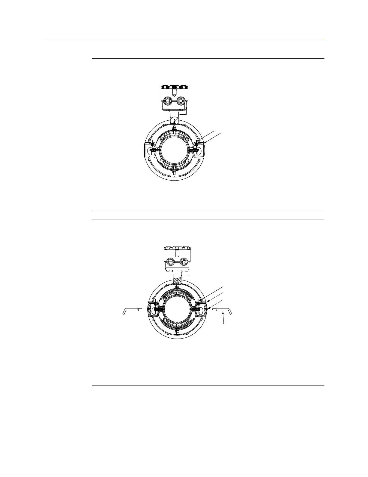
Advanced installation details
A. 2x fused glass seal
B. 2x sealed electrode compartment
8705 with M2 Coil Housing ConfigurationFigure 6-12:
A
B
8705 with M4 Coil Housing ConfigurationFigure 6-13:
A
B
С
D
A. 2x fused glass seal
B. 2x sealed electrode compartment
C. M6 threaded pressure relief port with removable cap screw
D. Optional: Use relief port to plumb to safe area (supplied by user).
62 Rosemount® 8732EM Transmitter with Modbus Protocol Reference Manual
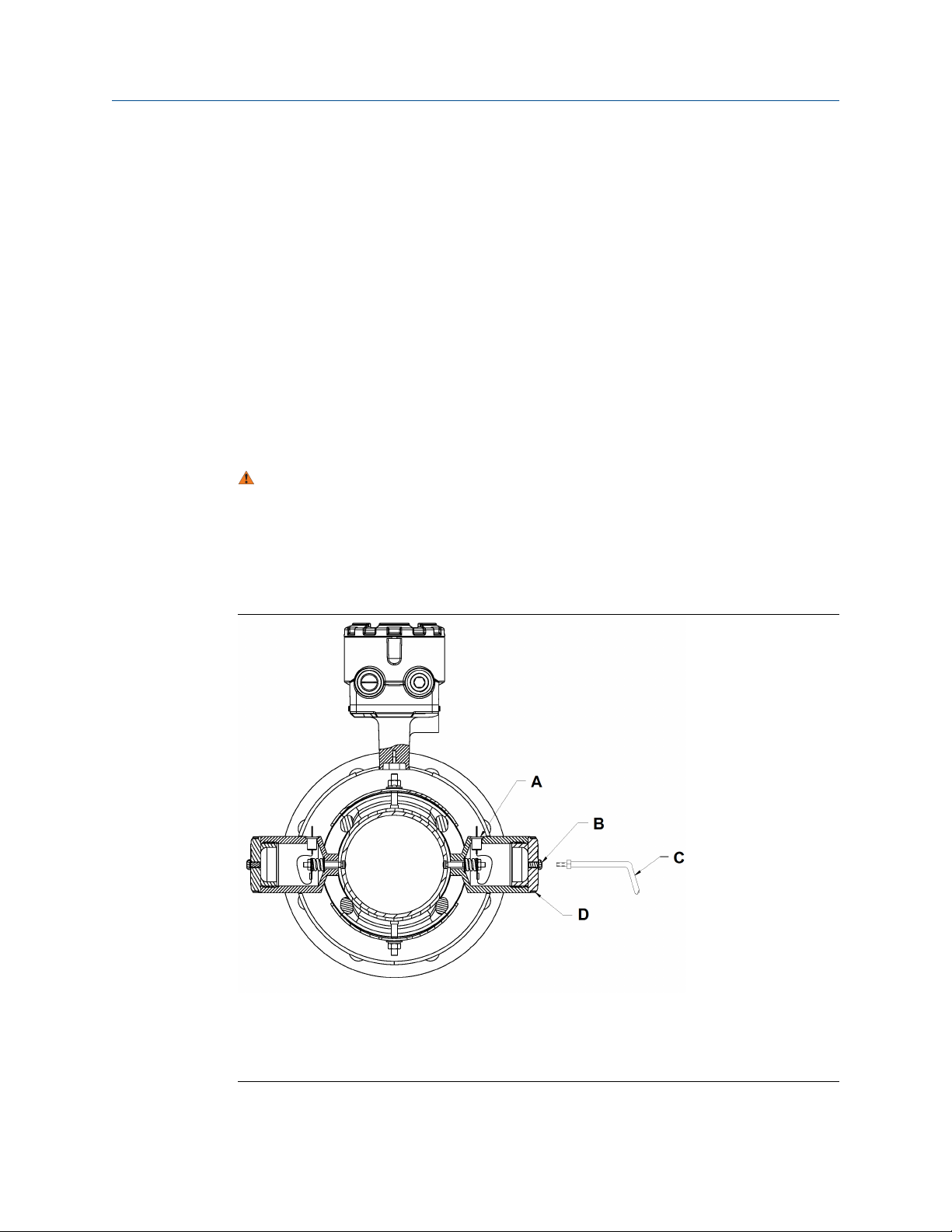
Advanced installation details
6.3.4 Process leak containment with electrode access (option M3)
The 8705 is available with Process Leak Containment and Electrode Access. The coil
housing configuration is a factory sealed, all-welded enclosure with the addition of sealed
electrode compartments that include access covers. The M3 configuration is available on
the 8705 only.
• 8705 with option code M3 - 8705xxxxxxxxM3
This configuration divides the coil housing into separate compartments, one for each
electrode and one for the coils. In the event of a primary seal failure, the fluid is contained
in the electrode compartment. The sealed electrode compartment prevents the process
fluid from entering the coil compartment where it may damage the coils and other internal
components. The electrode compartments are designed to contain the process fluid up to
a maximum pressure of 740 psig.
CAUTION!
To properly vent process fluid from the electrode compartment to a safe location, additional
piping is required and must be installed by the user. Installation of any associated piping must
be performed in accordance with environmental and hazardous area requirements. In the
event of primary seal failure, the electrode compartment may be pressurized. Use caution
when removing the cap screw.
A. 2X fused glass seal
B. 2X M6 threaded pressure relief port
C. Optional: use relief port to plumb to safe area (supplied by user)
D. Threaded electrode access cover
Reference manual 63
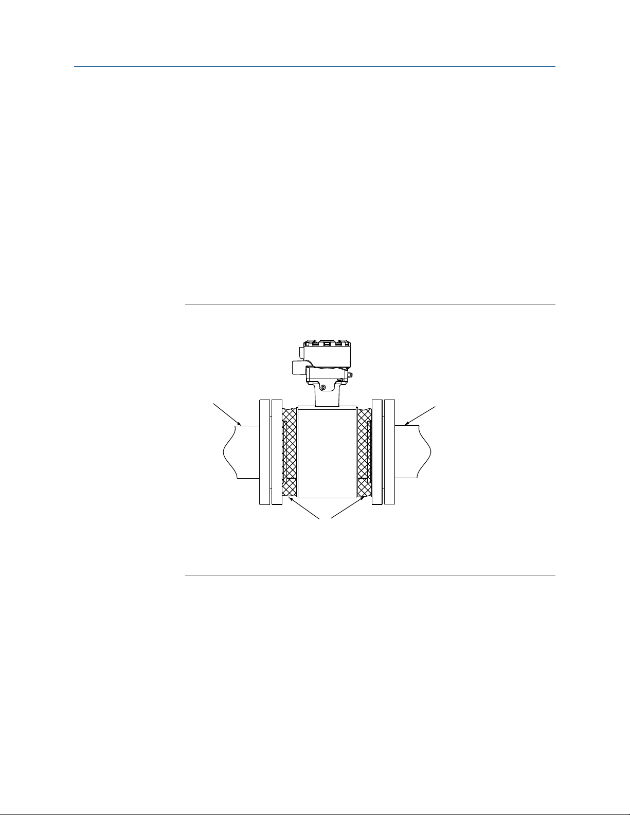
Advanced installation details
6.3.5 Higher temperature applications and sensor insulation best practices
Insulation of the magnetic flowmeter sensor is not typically recommended. However, in
applications with higher temperature process fluids (above 150°F / 65°C), plant safety,
sensor reliability, and sensor longevity can be improved with careful attention to proper
insulation.
Procedure
1. In applications where process fluid permeation of the liner has been observed or
may be expected, the rate of permeation can be reduced by decreasing the
temperature gradient between the process fluid and the outside of the meter body.
In these applications only the space between the process flanges and the coil
housing should be insulated (see Figure 6-14).
Insulating a Rosemount Magnetic Flowmeter for PermeationFigure 6-14:
A
B
C
A. Process piping
B. Coil housing
C. Insulation
2. When insulation of the magnetic flowmeter sensor is required due to plant safety
standards designed to protect personnel from contact burns, extend the insulation
up to the coil housing, covering both ends of the sensor and flanges (Figure 6-15).
The insulation should NOT cover the coil housing or the terminal junction box.
Insulating the coil housing and the terminal junction box can result in overheating of
the coil compartment and terminals, resulting in erratic/erroneous flow readings
and potential damage or failure of the meter.
A
64 Rosemount® 8732EM Transmitter with Modbus Protocol Reference Manual

Advanced installation details
Figure 6-15:
A
A. Process piping
B. Coil housing
C. Insulation
Insulating a Rosemount Magnetic Flowmeter for Safety/Plant
Standards
A
B
C
Reference manual 65

Advanced installation details
66 Rosemount® 8732EM Transmitter with Modbus Protocol Reference Manual

7 Operation
Topics covered in this chapter:
Introduction
•
Local operator interface (LOI)
•
7.1 Introduction
The transmitter features a full range of software functions, transmitter configurations, and
diagnostic settings. These features can be accessed through the Local Operator Interface
(LOI), ProLink III configuration software, or a host control system. Configuration variables
may be changed at any time; specific instructions are provided through on-screen
instructions.
This section covers the basic features of the LOI (optional) and provides general
instructions on how to navigate the configuration menus using the optical buttons. The
section also provides a menu tree to help access each function. For detailed LOI
configuration refer to Chapter 8.
Operation
7.2 Local operator interface (LOI)
The optional LOI provides a communications center for the transmitter.
The LOI allows an operator to:
• Change transmitter configuration
• View flow and totalizer values
• Start/stop and reset totalizer values
• Run diagnostics and view the results
• Monitor transmitter status
7.2.1
Basic features
The basic features of the LOI include a display window and four navigational arrow keys.
Reference manual 67

Operation
Local Operator Interface Keypad and Character DisplayFigure 7-1:
A
B
E
7.2.2
D
A. LEFT (E) key
B. UP key
C. DOWN key
D. RIGHT key
E. Display window
To access the LOI, press the DOWN arrow one time. Use the UP, DOWN, LEFT, and RIGHT
arrows to navigate the menu structure. A map of the LOI menu structure is shown in
Section 7.2.9.
C
Data entry
The LOI keypad does not have alphanumeric keys. Alphanumeric and symbolic data is
entered by the following procedure. Use the steps below to access the appropriate
functions.
Procedure
1. Use , , , and to navigate the menu (Section 7.2.9) and access the appropriate
alphanumeric parameter.
2. Use , or to begin editing the parameter.
• Press to go back without changing the value.
• For numerical data, scroll through the digits 0-9, decimal point, and dash.
• For alphabetical data, scroll through the letters of the alphabet A-Z, digits 0-9,
and the symbols ?, &, +, -, *, /, $, @,%, and the blank space.
3. Use to highlight each character you want to change and then use and to
select the value.
If you go past a character that you wish to change, keep using to wrap around and
arrive at the character you want to change.
68 Rosemount® 8732EM Transmitter with Modbus Protocol Reference Manual

4. Press when all changes are complete to save the entered values.
5. Press again to navigate back to the menu tree.
7.2.3 Data entry examples
Parameter values are classified as table values or select values.
• Table values are available from a predefined list for parameters such as line size or
flow units.
• Select values are integers, floating point numbers, or character strings and are
entered one character at a time using the arrow keys for parameters such as PV URV
and calibration number.
Table value example
Setting the sensor size:
Procedure
Operation
1. Press
2. Use , , , and to select line size from the basic setup menu.
3. Use or to increase/decrease the sensor size.
4. When you reach the desired sensor size, press .
5. Set the loop to manual if necessary, and press again.
After a moment, the LOI will display VALUE STORED SUCCESSFULLY and then display
the selected value.
key to access the menu. See Section 7.2.9.
Select value example
Changing the upper range limit:
Procedure
1. Press key to access the menu. See Section 7.2.9.
2. Use
3. Press to position the cursor.
4. Press or to set the number.
5. Repeat steps 3and 4 until desired number is displayed, press .
6. Set the loop to manual if necessary, and press again.
, , , and to select PV URV from the basic setup menu.
After a moment, the LOI will display VALUE STORED SUCCESSFULLY and then display
the selected value.
Reference manual 69

Operation
7.2.4 Dynamic variable display pause
To make dynamically changing variables easier to read and record, a pause feature has
been built into the LOI.
When viewing a dynamic variable (such as a totalizer value) from the view variable screen,
press to pause the display value. To return the screen to the dynamic display mode,
press again, or exit the screen by pressing .
Note
It is important to note this feature pauses only the display. While the display is paused, the
transmitter continues to measure all variables dynamically, and continues to increment the totalizer.
7.2.5 Totalizer functionality
Totalizer selection
• To view the totalizer values, press to access the LOI menu structure.
• To view the totalizer values, press VIEW TOTAL to access the LOI menu structure.
7.2.6
The first option is the totalizers. Under this section, you can view and configure the
totalizers. See Section 8.2.3 for more information on the totalizer functionality.
Start all / Stop all
Totalizers can be started or stopped simultaneously. See Section 8.2.3.
Reset totalizer
The totalizers can be configured to be reset through the LOI. They can be reset
individually, or simultaneously through a global command. For details on configuring the
reset functionality and on resetting the totalizers, refer to Section 8.2.3.
Display lock
The transmitter has display lock functionality to prevent unintentional configuration
changes. The display can be locked manually or configured to automatically lock after a set
period of time. When locked, the LOI will display the flow screen.
Manual display lock
To activate, hold the UP arrow for 3 seconds and follow the on-screen instructions. When
the display lock is activated, a lock symbol will appear in the lower right hand corner of the
display. To deactivate, hold the UP arrow for 3 seconds and follow the on-screen
instructions. When the display lock is deactivated, the lock symbol will no longer appear in
the lower right hand corner of the display.
70 Rosemount® 8732EM Transmitter with Modbus Protocol Reference Manual

Auto display lock
The transmitter can be configured to automatically lock the LOI. Follow the instructions
below to access configuration.
Procedure
1. Press to access the menu. See Section 7.2.9.
2. Scroll to and select LOI Config from the Detailed Setup menu.
3. Press to highlight Disp Auto Lock and press to enter the menu.
4. Press or to select the auto lock time.
5. When you reach the desired time, press .
6. Set the loop to manual if necessary, and press .
After a moment, the LOI will display VALUE STORED SUCCESSFULLY and then display
the selected value.
7.2.7 Diagnostic messages
Operation
Diagnostic messages may appear on the LOI. See Chapter 9 for a complete list of messages,
potential causes, and corrective actions for these messages.
7.2.8 Display symbols
When certain transmitter functions are active, a symbol will appear in the lower-right
corner of the display. The possible symbols include the following:
Display Lock
Totalizer
Reverse flow
Continuous meter verification
Reference manual 71

REV AJ
Totalizers
Diagnostics
Basic Setup
Detailed Setup
View Total A
View Total B
View Total C
Config/Control
Status All
Start All
Stop All
Reset All
Total A
Total B
Total C
Security
Reset Total A
Total A Config
LOI Control
Write Protect
TotA Direction
TotA Units
TotA Reset Cfg
Reset Total B
Total B Config
TotB Direction
TotB Units
TotB Reset Cfg
Reset Total C
Total C Config
TotC Direction
TotC Units
TotC Reset Cfg
LOI Start/Stop
LOI Reset
WP Start/Stop
WP Reset
Operation
7.2.9 LOI menu tree
Totalizers menu mapFigure 7-2:
72 Rosemount® 8732EM Transmitter with Modbus Protocol Reference Manual

Modbus Diag
Diag Controls
Basic Diag
Advanced Diag
Variables
Trims
Status
Empty Pipe
Process Noise
Ground/Wiring
Elec Coating
Elect Temp
Reverse Flow
Cont Meter Ver
Self Test
Pulse Out Test
Empty Pipe
Elect Temp
Flow Limit 1
Flow Limit 2
Total Limit
EP Control
EP Value
EP Trig Level
EP Counts
Ground/Wiring
Process Noise
Elec Coating
Meter Verif
Licensing
Run Meter Ver
View Results
Sensr Baseline
Test Criteria
Measurements
Test Condition
Test Criteria
MV Results
Sim Velocity
Actual Velocity
Flow Sim Dev
Xmtr Cal Verify
Sensor Cal Dev
Sensor Cal
Coil Circuit
Electrode Ckt
Values
Reset Baseline
Recall Values
Coil Resist
Coil Inductnce
Electrode Res
No Flow
Flowing, Full
Empty Pipe
Continual
Coil Resist
Coil Inductnce
Actual Velocity
Electrode Res
License Status
License Key
EC Current Val
EC Limit 1
EC Limit 2
EC Max Value
Reset Max Val
Process Noise
Ground/Wiring
Elec Coating
Meter Verif
DI/DO
Empty Pipe
Elect Temp
Line Noise
5Hz SNR
37Hz SNR
Elec Coating
Signal Power
37Hz Auto Zero
Coil Current
MV Results
EC Current Val
EC Max Value
Digital Trim
37Hz Auto Zero
Universal Trim
Test Criteria
Sim Velocity
Actual Velocity
Flow Sim Dev
Coil Inductnce
Sensor Cal Dev
Coil Resist
Electrode Res
Coils
Electrodes
Transmitter
Manual Results
Continual Res
Manual Results
Continual Res
Coil Resist
Coil Inductnce
Electrode Res
Actual Velocity
Flow Sim Dev
Manual Measure
Continual Meas
Totalizers
Diagnostics
Basic Setup
Detailed Setup
REV AJ
Test Criteria
Sim Velocity
Actual Velocity
Flow Sim Dev
Coil Inductnce
Sensor Cal Dev
Coil Resist
Electrode Res
Test Condition
Test Criteria
MV Results
Sim Velocity
Actual Velocity
Flow Sim Dev
Xmtr Cal Verify
Sensor Cal Dev
Sensor Cal
Coil Circuit
Electrode Ckt
Modbus Status
Listen Only MD
Restart MB Com
Reset MB Confg
Operation
Diagnostics menu mapFigure 7-3:
Reference manual 73
Modbus
Tag
Flow Units
Line Size
Cal Number
Damping
Flow Units
Special Units
Total A Units
Total B Units
Total C Units
Address
Flt Pt Order
Baud Rate
Parity
Stop Bits
Min Resp Delay
Variable Slots
Var Slot 0 Idx
Var Slot 1 Idx
Var Slot 2 Idx
Var Slot 3 Idx
Var Slot 4 Idx
Var Slot 5 Idx
Var Slot 6 Idx
Var Slot 7 Idx
Var Slot 8 Idx
Var Slot 9 Idx
Slot Indices
Slot Variables
Var Slot 0 Val
Var Slot 1 Val
Var Slot 2 Val
Var Slot 3 Val
Var Slot 4 Val
Var Slot 5 Val
Var Slot 6 Val
Var Slot 7 Val
Var Slot 8 Val
Var Slot 9 Val
Totalizers
Diagnostics
Basic Setup
Detailed Setup
REV AJ
Operation
Basic setup menu mapFigure 7-4:
74 Rosemount® 8732EM Transmitter with Modbus Protocol Reference Manual

More Params
Output Config
LOI Config
Sig Processing
Device Info
Device Reset
Coil Frequency
Proc Density
Flow LSL
Flow USL
Modbus
Pulse
DI/DO Config
Reverse Flow
Pulse Scaling
Pulse Width
Pulse Mode
Test
DI/O 1
DO 2
Flow Limit 1
Flow Limit 2
Total Limit
Diag Alert
Flow Display
Language
Disp Auto Lock
Backlight
Operating Mode
SP Config
Coil Frequency
Damping
Lo-Flow Cutoff
Tag
Description
Message
Device ID
Sensor S/N
Sensor Tag
Write protect
Revision Num
Software Rev
Final Asmbl #
DI/O 1 Control
DI 1
DO 1
Control 1
Mode 1
High Limit 1
Low Limit 1
Hysteresis
Total Control
Total Mode
Tot Hi Limit
Tot Low Limit
Hysteresis
Control 2
Mode 2
High Limit 2
Low Limit 2
Hysteresis
Elec Failure
Coil Open Ckt
Empty Pipe
Reverse Flow
Ground/Wiring
Process Noise
Elect Temp
Elec Coat 1
Elec Coat 2
Cont Meter Ver
Coil Over Curr
Sensr Elec Sat
Coil Power Lim
Address
Flt Pt Order
Baud Rate
Parity
Stop Bits
Min Resp Delay
Variable Slots
Var Slot 0 Idx
Var Slot 1 Idx
Var Slot 2 Idx
Var Slot 3 Idx
Var Slot 4 Idx
Var Slot 5 Idx
Var Slot 6 Idx
Var Slot 7 Idx
Var Slot 8 Idx
Var Slot 9 Idx
Slot Indices
Slot Variables
Var Slot 0 Val
Var Slot 1 Val
Var Slot 2 Val
Var Slot 3 Val
Var Slot 4 Val
Var Slot 5 Val
Var Slot 6 Val
Var Slot 7 Val
Var Slot 8 Val
Var Slot 9 Val
Totalizers
Diagnostics
Basic Setup
Detailed Setup
REV AJ
Operation
Detailed setup menu mapFigure 7-5:
Reference manual 75

Operation
76 Rosemount® 8732EM Transmitter with Modbus Protocol Reference Manual

8 Advanced Configuration
Functionality
Topics covered in this chapter:
Introduction
•
Configure outputs
•
Configure LOI
•
Additional parameters
•
Configure special units
•
8.1 Introduction
This section contains information for advanced configuration parameters.
Advanced Configuration Functionality
8.2
8.2.1
The software configuration settings for the transmitter can be accessed through the Local
Operator Interface (LOI) or a modbus host. Before operating the transmitter in an actual
installation, you should review all of the factory set configuration data to ensure that they
reflect the current application.
Configure outputs
LOI menu path Detailed Setup > Output Config
The configure outputs functionality is used to configure advanced features that control the
Modbus, pulse, auxiliary, and totalizer outputs of the transmitter.
Modbus output
Configure the Modbus communication parameters.
Address
LOI menu path
Modbus register 109
Detailed Setup > Output Config > Modbus > Address
Configure the address of the transmitter for the Modbus network. The acceptable range is
an integer value from 1 to 247. The default address is 1.
Reference manual 77

Advanced Configuration Functionality
Each register is identified by its address (or starting address). Depending on the PLC that
will be used to communicate with the transmitter, you may need to subtract 1 from the
address, or starting address, of the register. Refer to PLC documentation to determine if
this applies.
Floating point byte order
LOI menu path Detailed Setup > Output Config > Modbus > Flt Pt Order
Modbus register 110
Sets the order that information is sent by the transmitter.
Register value
0 0-1-2-3 (default)
1 2-3-0-1
2 1-0-3-2
3 3-2-1-0
Byte order
Baud rate
LOI menu path
Modbus register 115
Detailed Setup > Output Config > Modbus > Baud Rate
Sets the communication speed of the transmitter.
Register value
0 1200
1 2400
2 4800
3 9600
4 19200 (default)
5 38400
6 57600
7 115200
Baud rate
Parity
LOI menu path
Detailed Setup > Output Config > Modbus > Parity
78 Rosemount® 8732EM Transmitter with Modbus Protocol Reference Manual

Advanced Configuration Functionality
Modbus register 116
Used to configure error-checking methodology for the data.
Register value Parity
0 No parity
1 Odd
2 Even (default)
Stop bits
LOI menu path Detailed Setup > Output Config > Modbus > Stop Bits
Modbus register 117
Sets the last bit of the data packet.
Register value
1 1 bit (default)
2 2 bits
Stop bits
Minimum response delay
LOI menu path
Modbus register 111
Detailed Setup > Output Config > Modbus > Min Resp Delay
Minimum response delay is used to synchronize Modbus communications with hosts that
operate at a slower speed than the transmitter. The value specified here will be the
minimum elapsed time before the transmitter sends a response to the host. This value can
be configured as an integer from 0 to 250 ms. The default value is 10 ms.
Note
Do not set the minimum response delay unless required by the Modbus host.
Variable slots
LOI menu path
Detailed Setup > Output Config > Modbus > Variable Slots
Reference manual 79

Advanced Configuration Functionality
Variable slots allows for the customization of variables into fixed Modbus register locations.
Up to 30 slots can be configured using ProLink III or a Modbus configuration tool. Through
the LOI, configuration functionality is limited to 10 slots.
Slot indices
LOI menu path Detailed Setup > Output Config > Modbus > Slot Indices
Modbus register 651–680
Assign variables to the various Modbus slots for easy reference. Slots 0 through 9 can be
configured through the LOI, ProLink III, or a Modbus configuration tool. Slots 10 through
29 can only be configured through ProLink III or a Modbus configuration tool.
Slot variables can be assigned to the slots.
Register value
0 Flow rate
1 Pulse output frequency
2 Totalizer A
3 Totalizer B
4 Totalizer C
5 Electronics temperature
6 Line noise
7 5 Hz signal to noise ratio
8 37 Hz signal to noise ratio
9 Signal power
10 Empty pipe value
11 Continuous internal flow simulator test deviation
12 Electrode coating value
13 Continuous electrode resistance value
14 Continuous coil resistance value
15 Continuous coil inductance value
16 Continuous coil inductance deviation value
Variable
Slot variables
LOI menu path
Modbus register 691–749
Detailed Setup > Output Config > Modbus > Variable Slots > Slot
Variables
80 Rosemount® 8732EM Transmitter with Modbus Protocol Reference Manual

View the variable values indexed to slots 0 through 9 on the LOI. Slots 10 through 29 can
only be viewed through ProLink III or a Modbus configuration tool. These are read-only
variables.
8.2.2 Pulse output
LOI menu path Detailed Setup > Output Config > Pulse
Under this function the pulse output of the transmitter can be configured.
Pulse scaling
LOI menu path Detailed Setup > Output Config > Pulse > Pulse Scaling
Modbus register 327–328
Transmitter may be commanded to supply a specified frequency between 1 pulse/ day at
39.37 ft/sec (12 m/s) to 10,000Hz at 1 ft/sec (0.3 m/s).
Advanced Configuration Functionality
Note
Line size, special units, and density must be selected prior to configuration of the pulse scaling
factor.
The pulse output scaling equates one transistor switch closure pulse to a selectable
number of volume units. The volume unit used for scaling pulse output is taken from the
numerator of the configured flow units. For example, if gal/min had been chosen when
selecting the flow unit, the volume unit displayed would be gallons.
Note
The pulse output scaling is designed to operate between 0 and 10,000Hz. The minimum conversion
factor value is found by dividing the minimum span (in units of volume per second) by 10,000Hz.
Note
The maximum pulse scaling frequency for transmitters with an intrinsically safe output (output
option code B) is 5000Hz.
When selecting pulse output scaling, the maximum pulse rate is 10,000Hz. With the 110
percent over range capability, the absolute limit is 11,000Hz. For example, if you want the
transmitter to pulse every time 0.01 gallons pass through the sensor, and the flow rate is
10,000 gal/min, you will exceed the 10,000Hz full-scale limit:
10,000 gal
1 min
1 min
(60 sec)
××
1 pulse
0.01 gal
= 16,666.7 Hz
Reference manual 81

Advanced Configuration Functionality
The best choice for this parameter depends upon the required resolution, the number of
digits in the totalizer, the extent of range required, and the maximum frequency limit of
the external counter.
Pulse factor units
Modbus register 37
The pulse factor unit assigns the unit of measure to the pulse scaling factor. The default
read-only value is the unit of measure from the configured flow units. For example, if
gal/min is selected when configuring the flow units, the pulse factor unit will be gallons.
Register value Units
40 Gallons
41 Liters
42 Imperial gallons
43 Cubic meters
46 Barrels (42 gallons)
112 Cubic feet
246 Cubic centimeters
247 Barrels (31 gallons)
249 Millions gallons
Pulse factor volume unitsTable 8-1:
Pulse factor mass unitsTable 8-2:
Register value Units
61 Kilograms
62 Metric tons
63 Pounds
64 Short tons
Pulse factor other unitsTable 8-3:
Register value Units
44 Feet
45 Meters
82 Rosemount® 8732EM Transmitter with Modbus Protocol Reference Manual

Advanced Configuration Functionality
Pulse factor other units (continued)Table 8-3:
Register value Units
253 Special units
(1) See Section 8.5.
(1)
Pulse width
LOI menu path Detailed Setup > Output Config > Pulse > Pulse Width
Modbus register 329, 330
The factory default pulse width is 0.5 ms.
The width, or duration, of the pulse can be adjusted to match the requirements of different
counters or controllers (see Figure 8-1). These are typically lower frequency applications (<
1000Hz). The transmitter will accept values from 0.1 ms to 650 ms.
For frequencies higher than 1000Hz, it is recommended to set the pulse mode to 50% duty
cycle by setting the pulse mode to frequency output.
The pulse width will limit the maximum frequency output, If the pulse width is set too wide
(more than 1/2 the period of the pulse) the transmitter will limit the pulse output. See
example below.
Pulse OutputFigure 8-1:
A
B
D
C
A. Open
B. Pulse width
C. Period
D. Closed
Example
If pulse width is set to 100 ms, the maximum output is 5Hz; for a pulse width of 0.5 ms, the
maximum output would be 1000Hz (at the maximum frequency output there is a 50%
duty cycle).
Reference manual 83

Advanced Configuration Functionality
Pulse width
100 ms 200 ms
Minimum period (50% duty
cycle) Maximum frequency
1 cycle
200 ms
= 5 Hz
0.5 ms 1.0 ms
1 cycle
1.0 ms
= 1000 Hz
To achieve the greatest maximum frequency output, set the pulse width to the lowest
value that is consistent with the requirements of the pulse output power source, pulse
driven external totalizer, or other peripheral equipment.
The maximum flow rate is 10,000 gpm. Set the pulse output scaling such that the
transmitter outputs 10,000Hz at 10,000 gpm.
Pulse Scaling =
Pulse Scaling =
Pulse Scaling = 0.0167
1 pulse = 0.0167 gal
Flow Rate (gpm)
sec
(60 ×)
min
10,000 gpm
sec
(60 ×)
min
gal
pulse
(frequency)
(10,000 Hz)
Note
Changes to pulse width are only required when there is a minimum pulse width required for external
counters, relays, etc.
The external counter is ranged for 350 gpm and pulse is set for one gallon. Assuming the
pulse width is 0.5 ms, the maximum frequency output is 5.833Hz.
Frequency =
Pulse Scaling =
Frequency = 5.833 Hz
Flow Rate (gpm)
sec
(60 ×) )(
min
(60 ×)
pulse scaling
350 gpm
sec
1
min
pulse
gal
pulse
gal
The upper range value (20mA) is 3000 gpm. To obtain the highest resolution of the pulse
output, 10,000Hz is scaled to the full scale analog reading.
Frequency =
Flow Rate (gpm)
sec
(60 ×) )(
min
pulse scaling
gal
pulse
84 Rosemount® 8732EM Transmitter with Modbus Protocol Reference Manual

Advanced Configuration Functionality
Pulse Scaling =
Pulse Scaling = 0.005
1 pulse = 0.005 gal
3,000 gpm
sec
(60 ×)
min
gal
pulse
10,000 Hz
Pulse mode
LOI menu path Detailed Setup > Output Config > Pulse > Pulse Mode
Modbus register 85
The pulse mode configures the frequency output of the pulse. It can be set to either 50%
duty cycle, or fixed. There are two options that pulse mode can be configured to:
• Pulse Output (user defines a fixed pulse width)
• Frequency Output (pulse width automatically set to 50% duty cycle)
Register value
0 Pulse Output: User defines a fixed pulse width (default)
1 Frequency Output: Pulse width automatically set to 50% duty cy-
Mode
cle
8.2.3
To use pulse width settings, pulse mode must be set to pulse output.
Totalizer
The totalizer provides the total amount of fluid that has passed through the meter. There
are three available totalizers: Total A, Total B, and Total C. They can be independently
configured for one of the following options:
• Net - increments with forward flow and decrements with reverse flow (reverse flow
must be enabled).
• Reverse total - will only increment with reverse flow if reverse flow is enabled
• Forward total - will only increment with forward flow
All totalizer values will be reset if line size is changed. This will happen even if the totalizer
reset control is set to non-resettable.
The totalizers have the capability to increment the total to a maximum value of 50 feet per
second of flow (or the volumetric equivalent) for a period of 20 years before roll-over
occurs.
Reference manual 85

Advanced Configuration Functionality
View Totals
LOI menu path Totalizer A: Totalizers > View Total A
Modbus registers Totalizer A: 203, 204
Displays the current value for each totalizer and shows the totalizer incrementing/
decrementing based on totalizer configuration and flow direction.
Configure totalizers
LOI menu path Totalizers > Config/Control
Modbus registers 101, 103
Totalizer B: Totalizers > View Total B
Totalizer C: Totalizers > View Total C
Totalizer B: 205, 206
Totalizer C: 207, 208
Start, stop, and reset all totalizers, configure the independent totalizers, and security
controls for write protecting and resetting the individual totalizers.
Totalizer funtion
Start all totalizers 101 1
Stop all totalizers 101 0
Reset all totalizers 103 1
Note
If an individual totalizer is configured as non-resettable, the global totalizer reset command will not
affect that totalizer.
Note
If an individual totalizer is configured as write protected, the global totalizer start/stop/reset
commands will not affect that totalizer.
Modbus coil Modbus coil value
Totalizer direction
LOI menu path
Totalizer A: Totalizers > Config/Control > Total A > Total A Config
> Direction
Totalizer B: Totalizers > Config/Control > Total B > Total B Config
> Direction
Totalizer C: Totalizers > Config/Control > Total C > Total C Config
> Direction
86 Rosemount® 8732EM Transmitter with Modbus Protocol Reference Manual

Advanced Configuration Functionality
Modbus register Totalizer A: 101
Totalizer B: 103
Totalizer C: 105
Configure the direction for the totalizers as either Net, Forward, or Reverse.
Register value Totalizer direction
0 Net (default for Total A)
1 Forward (default for Total B)
2 Revers (default for Total C)
Totalizer units
LOI menu path Totalizer A: Totalizers > Config/Control > Total A > Total A Config
> TotA Units
Totalizer B: Totalizers > Config/Control > Total B > Total B Config
> TotB Units
Totalizer C: Totalizers > Config/Control > Total C > Total C Config
> TotC Units
Modbus register Totalizer A: 62
Totalizer B: 63
Totalizer C: 64
Configure the units for totalizers.
Totalizer volume unitsTable 8-4:
Register value Units
40 Gallons
41 Liters
42 Imperial gallons
43 Cubic meters
46 Barrels (42 gallons)
112 Cubic feet
246 Cubic centimeters
247 Barrels (31 gallons)
Reference manual 87

Advanced Configuration Functionality
Register value Units
61 Kilograms
62 Metric tons
63 Pounds
64 Short tons
Register value Units
44 Feet (default)
45 Meters
253 Special units (see Section 8.5.)
Reset configuration
Totalizer mass unitsTable 8-5:
Totalizer other unitsTable 8-6:
LOI menu path Totalizer A: Totalizers > Config/Control > Total A > Total A Config
> TotA Reset Config
Totalizer B: Totalizers > Config/Control > Total B > Total B Config
> TotB Reset Config
Totalizer C: Totalizers > Config/Control > Total C > Total C Config
> TotC Reset Config
Modbus register Totalizer A: 100
Totalizer B: 102
Totalizer C: 104
Configure if the totalizer is non-resettable, or if it can be reset through the reset
commands.
Register value
0 Not resetable (default for Totalizer B & C)
1 Resetable (default for Totalizer A)
Reset options
Reset individual totalizer
LOI menu path
Totalizer A: Totalizers > Config/Control > Total A > Reset Total A
Totalizer B: Totalizers > Config/Control > Total B > Reset Total B
Totalizer C: Totalizers > Config/Control > Total C > Reset Total C
88 Rosemount® 8732EM Transmitter with Modbus Protocol Reference Manual

Advanced Configuration Functionality
Modbus coil Totalizer A: 104
Totalizer B: 105
Totalizer C: 106
Independently reset the totalizers. This requires the reset option to be configured as
resettable.
Register value Reset options
0 Run
1 Reset
Reset all totalizers
LOI menu path Totalizers > Config/Control > Reset All
Modbus coil 103
This global command will reset totalizer values to zero for all totalizers that have been
configured as resettable.
Register value
0 Run
1 Reset
Reset options
Totalizer security
LOI menu path
Totalizers > Config/Control > Security
Configure totalizer security capabilities for the Local Operator Interface and write
protection.
LOI control
LOI menu path
Totalizers > Config/Control > Security > LOI Control
Configure the ability to start, stop, and reset the totalizers through the LOI.
LOI totalizer start/stop
LOI menu path
Totalizers > Config/Control > Security > LOI Control > LOI Start/
Stop
Reference manual 89

Advanced Configuration Functionality
Modbus coil 141
Enable/disable the ability to start or stop totalizers through the LOI.
Modbus coil value Operating mode
0 Prevent totalizer reset through the LOI
1 Allow totalizer reset through the LOI (default)
LOI totalizer reset
LOI menu path Totalizers > Config/Control > Security > LOI Control > LOI Reset
Enable/disable the ability to reset the totalizers through the LOI.
Totalizer write protection
LOI menu path Totalizers > Config/Control > Security > Write Protect
In addition to controlling the LOI capability to start/stop and reset the totalizers, specific
write protect functionality can also be configured adding an additional level of security to
the totalizers.
Start/stop write protect
LOI menu path
Modbus coil 139
Totalizers > Config/Control > Security > Write Protect > WP Start/
Stop
Configure write protection on the ability to start or stop the totalizers. This is a global
command and applies to all totalizers.
Register value
0 Disable totalizer start/stop write protect (default)
1 Enable totalizer start/stop write protect
Reset options
Reset write protect
LOI menu path
Modbus coil 140
Totalizers > Config/Control > Security > Write Protect > WP Reset
90 Rosemount® 8732EM Transmitter with Modbus Protocol Reference Manual

Configure write protection on the ability to reset the totalizers. This is a global command
and applies to all totalizers.
Register value Reset options
0 Disable totalizer reset write protect (default)
1 Enable totalizer reset write protect
8.2.4 Discrete input/output
This configuration option is only available if the auxiliary output suite (option code AX) was
ordered. The auxiliary output suite provides two channels for control.
• The discrete input can provide positive zero return (PZR) and net totalizer reset.
• The discrete output control function can be configured to drive an external signal to
indicate zero flow, reverse flow, empty pipe, diagnostic status, flow limit, or
transmitter status.
A complete list and description of the available auxiliary functions is provided below.
Advanced Configuration Functionality
Discrete input options (Channel 1 only)
PZR (Positive Zero
Return)
Net Total Reset
Discrete output options
Reverse Flow
Zero Flow
Transmitter Fault
Empty Pipe
Flow Limit 1
Flow Limit 2
Diagnostic Status
Alert
Total Limit
When conditions are met to activate the input, the transmitter
will force the output to zero flow.
When conditions are met to activate the input, the transmitter
will reset the net total value to zero.
The output will activate when the transmitter detects a reverse
flow condition.
The output will activate when a no flow condition is detected.
The output will activate when a transmitter fault condition is
detected.
The output will activate when the transmitter detects an empty
pipe condition.
The output will activate when the transmitter measures a flow
rate that meets the conditions established for the flow limit 1
alert.
The output will activate when the transmitter measures a flow
rate that meets the conditions established for the flow limit 2
alert.
The output will activate when the transmitter detects a condition
that meets the configured criteria of the diagnostic status alert.
The output will activate when the transmitter Totalizer A value
meets the conditions established for the total limit alert.
Reference manual 91

Advanced Configuration Functionality
Channel 1
Channel 1 can be configured as either a discrete input (DI) or as a discrete output (DO).
DI/O 1 control
LOI menu path Detailed Setup > Output Config > DI/DO Config > DI/O 1 > DI/O 1
Modbus register 91
This parameter configures the auxiliary output channel 1. It controls whether channel 1
will be a discrete input or discrete output on terminals 5(-) and 6(+).
Note
The transmitter must have been ordered with the auxiliary output suite (option code AX) to have
access to this functionality.
Control
Register value
1 Input (default)
2 Output
251 Not available
Operating mode
Discrete input 1
LOI menu path
Modbus register 92
Detailed Setup > Output Config > DI/DO Config > DI/O 1 > DI 1
This parameter displays the configuration for channel 1 when used as a discrete input.
Register value
0 PZR (default)
1 Totalizer A reset
2 Totalizer B reset
3 Totalizer C reset
251 Not available
Configuration
Discrete output 1
LOI menu path
Detailed Setup > Output Config > DI/DO Config > DI/O 1 > DO 1
92 Rosemount® 8732EM Transmitter with Modbus Protocol Reference Manual

Advanced Configuration Functionality
Modbus register 93
This parameter displays the configuration for channel 1 when used as a discrete output.
Register value Configuration
0 Reverse flow
1 Zero flow (default)
2 Transmitter fault
3 Empty pipe
4 Flow limit 1
5 Flow limit 2
6 Diagnostic status alert
7 Totalizer limit 1
251 Reset all
Channel 2
Channel 2 is available as discrete output only.
Discrete output 2
LOI menu path
Modbus register 96
Detailed Setup > Output Config > DI/DO Config > DO 2
This parameter displays the configuration for channel 2.
Register value
0 Reverse flow
1 Zero flow (default)
2 Transmitter fault
3 Empty pipe
4 Flow limit 1
5 Flow limit 2
6 Diagnostic status alert
7 Totalizer limit 1
251 Reset all
Configuration
Reference manual 93

Advanced Configuration Functionality
Flow limit (1 and 2)
There are two configurable flow limits. Configure the parameters that will determine the
criteria for activation of a diagnostic alert if the measured flow rate falls within a set of
configured criteria. This functionality can be used for operating simple batching
operations or generating alerts when certain flow conditions are met. This parameter can
be configured as a discrete output if the transmitter was ordered with the auxiliary output
suite (option code AX) and the outputs are enabled. If a discrete output is configured for
flow limit, the discrete output will activate when the conditions defined under mode
configuration are met. See Mode below.
Control
LOI menu path Flow 1: Detailed Setup > Output Config > DI/DO Config > Flow
Modbus coil Flow limit 1: 97
Limit 1 > Control 1
Flow 2: Detailed Setup > Output Config > DI/DO Config > Flow
Limit 2 > Control 2
Flow limit 2: 98
This parameter turns the flow limit diagnostic alert ON or OFF.
ON
The transmitter will generate a diagnostic alert when the defined conditions are
met. If a discrete output is configured for flow limit, the discrete output will
activate when the conditions for mode are met.
OFF
The transmitter will not generate an alert for the flow limit.
Modbus coil value Configuration
0 Off (default)
1 On
Mode
LOI menu path
Modbus register Flow limit 1: 97
Flow 1: Detailed Setup > Output Config > DI/DO Config > Flow
Limit 1 > Mode 1
Flow 2: Detailed Setup > Output Config > DI/DO Config > Flow
Limit 2 > Mode 2
Flow limit 2: 98
The mode parameter sets the conditions under which the flow limit diagnostic alert will
activate. High and low limits exist for each channel and can be configured independently.
94 Rosemount® 8732EM Transmitter with Modbus Protocol Reference Manual
 Loading...