

848T Multisensor Transmitter Temperature Inputs with FOUNDATION Fieldbus-Interfacing Analog Transmitters to FOUNDATION
Rosemount 848T Multisensor Transmitter Temperature Inputs with FOUNDATION Fieldbus-Interfacing Analog Transmitters to FOUNDATION Manual Supplement

Manual Supplement
00809-0400-4697, Rev AA
April 2003
Interfacing Analog Transmitters to
OUNDATION
F
INSTALLING THE MODEL 848T WITH AN ANALOG CONNECTOR
The analog connector converts the 4–20 mA signal to a 20–100 mV signal. The
Model 848T transmitter uses a standard mV sensor type to output the scaled 4–20
mA signal onto the F
Use the following steps when installing the Model 848T with the analog connector:
1. The Model 848T, when ordered with option code S002, comes with four
analog connectors. Replace the standard connector with the analog
connector on the desired channels.
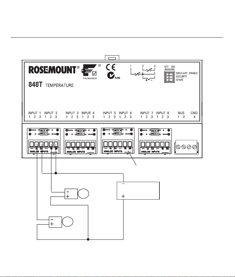
2. Wire one or two analog transmitters to the analog connector according to
Figure 1-1. There is space available on the analog connector label for
identification of the analog inputs.
NOTE
Power supply should be rated to support the connected transmitter(s).
™
Fieldbus
OUNDATION fieldbus.
3. If the analog transmitters can communicate using the HART protocol, the
analog connectors are supplied with the ability to switch in a 250 ohm resistor
for HART communication (see Figure 1-2).
One switch is supplied for each input (top switch for “A” inputs and bottom
switch for “B” inputs). Setting the switch in the “ON” position (to the right)
bypasses the 250 ohm resistor. Terminals are provided for each analog input
to connect a HART communicator for local configuration.
Model 848T
Figure 1-1. Model 848T Analog Input Wiring Diagram
CHANHASSEN, MN. USA
MODEL 848TNA5S001T1
SERIAL NO. 555999
FACTORY CAL. 0 to 100 DEG. C
FOUNDATION TYPE 11X BUS-POWERED
TT-101
Analog Transmitters
Power
Manual Supplement
00809-0400-4697, Rev AA
April 2003
Analog Input
S-2

Manual Supplement
00809-0400-4697, Rev AA
April 2003
Figure 1-2. Model 848T Analog Connector
250 ohm resistor in the loop when switched to the left
Model 848T
HART
Channel A
HART
Channel B
Space available for
identification of inputs
S-3

Manual Supplement
00809-0400-4697, Rev AA
Model 848T
April 2003
CONFIGURING THE MODEL 848T WITH THE ANALOG CONNECTOR
Sensor Transducer Block Configuration
Use the sensor configuration method to set the sensor type to mV – 2-wire for the
applicable transducer block or follow these steps.
1. Set the MODE_BLK.TARGET to out of service (OOS).
2. Set the SENSOR_TYPE to mV.
3. Set the MODE_BLK.TARGET to AUTO.
Analog Input Block Configuration
Follow these steps to configure the applicable Analog Input Block:
1. Set the MODE_BLK.TARGET to OOS.
2. Set CHANNEL to the transducer block configured for the analog input.
3. Set XD_SCALE.EU_0 to 20
Set XD_SCALE.EU_100 to 100
Set XD_SCALE.ENGUNITS to mV
4. SET OUT_SCALE to match the desired scale and units for the connected
analog transmitter.
Flow Example: 0 – 200 gpm
OUT_SCALE.EU_0 = 0
OUT_SCALE.EU_100 = 200
OUT_SCALE.ENGUNITS = gpm
5. Set L_TYPE to INDIRECT.
6. Set the MODE_BLK.TARGET to AUTO.
S-4
 Loading...