

Page 1
Models 396P and 396PVP
Combination pH/ORP
Sensor
Instruction Manual
PN 5100396P
February 2001
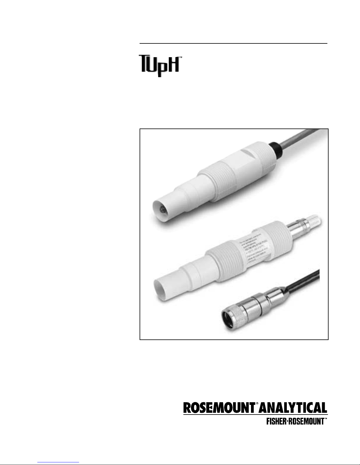
MODEL 396P
MODEL 396PVP
with mating cable
Page 2

CAUTION
SENSOR/PROCESS
APPLICATION COMPATIBILITY
The wetted sensor materials may not
be compatible with process composition and operating conditions.
Application compatibility is entirely the
responsibility of the user.
DANGER
HAZARDOUS AREA INSTALLATION
This sensor is not Intrinsically Safe. or
Explosion Proof. Installations near flammable
liquids or in hazardous area locations must
be carefully evaluated by qualified on site
safety personnel.
To secure and maintain an intrinsically safe
installation, an appropriate transmitter/
safety barrier/sensor combination must be
used. The installation system must be in
accordance with the governing approval
agency (FM, CSA or BASEEFA/CENELEC)
hazardous area classification requir ements.
Consult your analyzer/transmitter instruction
manual for details.
Proper installation, operation and servicing
of this sensor in a Hazardous Area Installation is entirely the responsibility of the user.
SS-SE
August 1995
ESSENTIAL INSTRUCTIONS
READ THIS PAGE BEFORE PROCEEDING!
Rosemount Analytical designs, manufactures, and tests
its products to meet many national and international standards. Because these instruments are sophisticated technical products, you must properly install, use, and maintain them to ensure they continue to operate within their
normal specifications. The following instructions must be
adhered to and integrated into your safety program when
installing, using, and maintaining Rosemount Analytical
products. Failure to follow the proper instructions may
cause any one of the following situations to occur: Loss of
life; personal injury; property damage; damage to this
instrument; and warranty invalidation.
• Read all instructions prior to installing, operating, and
servicing the product. If this Instruction Manual is not
the correct manual, telephone 1-800-654-7768 and the
requested manual will be provided. Save this
Instruction Manual for future reference.
• If you do not understand any of the instructions, contact
your Rosemount representative for clarification.
• Follow all warnings, cautions, and instructions marked
on and supplied with the product.
• Inform and educate your personnel in the proper installation, operation, and maintenance of the product.
• Install your equipment as specified in the Installation
Instructions of the appropriate Instruction Manual and
per applicable local and national codes. Connect all
products to the proper electrical and pressure sources.
• To ensure proper performance, use qualified personnel
to install, operate, update, program, and maintain the
product.
• When replacement parts are required, ensure that qualified people use replacement parts specified by
Rosemount. Unauthorized parts and procedures can
affect the product’s performance and place the safe
operation of your process at risk. Look alike substitutions may result in fire, electrical hazards, or improper
operation.
Rosemount Analytical Inc.
Uniloc Division
2400 Barranca Parkway
Irvine, CA 92606 USA
Tel: (949) 863-1181
http://www.RAuniloc.com
Page 3

i
MODEL 396P and 396PVP TABLE OF CONTENTS
MODEL 396P and 396PVP
COMBINATION pH/ORP SENSOR
TABLE OF CONTENTS
Section Title Page
11..00 DDEESSCCRRIIPPTTIIOONN AANNDD SSPPEECCIIFFIICCAATTIIOONNSS ...................................................................................................................................... 11
1.1 Features and Applications....................................................................................... 1
1.2 Physical Specifications............................................................................................ 1
1.3 Ordering Information................................................................................................ 2
22..00 IINNSSTTAALLLLAATTIIOONN................................................................................................................................................................................................................ 44
2.1 Unpacking and Inspection ...................................................................................... 4
2.2 Mounting.................................................................................................................. 4
33..00 WWIIRRIINNGG MMOODDEELL 339966PP-0011................................................................................................................................................................................ 99
44..00 WWIIRRIINNGG MMOODDEELLSS 339966PP-0022 AANNDD 339966PPVVPP................................................................................................................................ 1155
55..00 SSTTAARRTT UUPP AANNDD CCAALLIIBBRRAATTIIOONN.............................................................................................................................................................. 2222
5.1 Model 396P pH........................................................................................................ 22
5.2 Model 396P ORP ..................................................................................................... 22
66..00
MMAAIINNTTEENNAANNCCEE .............................................................................................................................................................................................................. 2233
6.1 Automatic Temperature Compensator..................................................................... 23
6.2 Model 396P pH........................................................................................................ 23
6.3 Model 396P ORP ..................................................................................................... 24
77..00 DDIIAAGGNNOOSSTTIICCSS AANNDD TTRROOUUBBLLEESSHHOOOOTTIINNGG ........................................................................................................................ 2255
7.1 Diagnostics & Troubleshooting With the Models 54, 3081, 81, and 4081.............. 25
7.2 Troubleshooting Without Advanced Diagnostics..................................................... 26
88..00 RREETTUURRNN OOFF MMAATTEERRIIAALL...................................................................................................................................................................................... 2288
8.1 General.................................................................................................................... 28
8.2 Warranty Repair....................................................................................................... 28
8.3 Non Warranty Repair................................................................................................ 28
LIST OF TABLES
Number Title Page
1-1 Recommended Accessories for First Time Installations.......................................... 3
3-1 Wiring Matrix Guide - Model 396P........................................................................... 9
4-1 Wiring Matrix Guide - Model 396PVP....................................................................... 15
5-1 ORP of Saturated Quinhydrone Solution (In Millivolts)............................................. 22
6-1 Ro and R1 Values for Temperature Compensation Elements .................................. 23
6-2 Temperature vs Resistance of Auto T.C. Elements .................................................. 23
7-1 Troubleshooting With Advanced Diagnostics.......................................................... 25
7-2 Troubleshooting Without Advanced Diagnostics..................................................... 26
7-3
Model 396P Replacement Parts and Accessories................................................... 27
Page 4

MODEL 396P and 396PVP TABLE OF CONTENTS
LIST OF FIGURES
Number Title Page
2-1 Dimensional Drawing .......................................................................................................................................................... 5
2-2 Flow-Through Tee with Adapter (PN 915240-xx)................................................................................................................. 5
2-3 Flow-Through and Insertion Installations ........................................................................................................................... 6
2-4 Model 396P/396PVP with Insertion Mounting Adapter (PN 23242-02)............................................................................... 6
2-5 Submersion Installations .................................................................................................................................................... 7
2-6 Low Flow Cell PN 23728-00 ................................................................................................................................................ 8
2-7 Jet Spray Cleaner PN 12707-00.......................................................................................................................................... 8
3-1 Wire Functions for Model 396P with & without Preamplifier................................................................................................ 10
3-2 Wiring Details Model 396P-01-50 for use with & without Junction Box (PN 22719-02) for Models 1181, 1050, & 1060.... 11
3-3 Wiring Details Model 396P-01-54 for use with & sithout Junction Box (PN 22719-02) for Models 1054/A/B, 2054, 2081
and Extension Cable (PN 9200254).................................................................................................................................... 12
3-4 Wiring Details Model 396P-01-55 for use with Junction Box (PN 23550-00) for Models 54, 3081, 4081, and 81 ............. 13
3-5 Wiring Details Model 396P-01-55 for use with Models 54, 81, 3081, and 4081 ................................................................. 14
3-6 Wiring Model 396P-01)-( )-55 Sensor to Model 1055-10-22-32 Analyzer........................................................................... 14
4-1 Wire Functions for Mating Variopol Cable used with Model 396PVP.................................................................................. 16
4-2 Connector Pins and their Functions.................................................................................................................................... 16
4-3 Wiring Details for Models 396PVP or 396P-02-55 with Mating Variopol Cable (PN 23645-07) for use with Model 81....... 16
4-4 Wiring Details for Models 396PVP or 396P-02-50 with Mating Variopol Cable (PN 23645-07) for use with Model 1181... 16
4-5 Wiring Details for Models 396PVP or 396P-02-54 with Mating Variopol Cable (PN 23645-07) for use with Model 2081... 16
4-6 Wiring Details for Models 396PVP or 396P-02-55 with Mating Variopol Cable (PN 23645-07) for use with Models 3081
and 4081............................................................................................................................................................................. 16
4-7 Wiring Details for Models 396PVP or 396P-02-55 with Mating Variopol Cable (PN 23645-07) for use with Remote .........
Junction Box (PN 23555-00) to Model 81 ........................................................................................................................... 17
4-8 Wiring Details for Models 396PVP or 396P-02-50 with Mating Variopol Cable (PN 23645-07) for use with Remote .........
Junction Box (PN 23309-03) to Model 1181 ....................................................................................................................... 17
4-9 Wiring Details for Models 396PVP or 396P-02-55 with Mating Variopol Cable (PN 23645-07) for use with Model 54...... 17
4-10 Wiring Details for Models 396PVP or 396P-02-55 with Mating Variopol Cable (PN 23645-07) for use with Remote .........
Junction Box (PN 23555-00) to Model 54 ........................................................................................................................... 17
4-11 Wiring Details for Models 396PVP or 396P-02-54 with Mating Variopol Cable (PN 23645-06) for use with Remote .........
Junction Box (PN 23309-03) to Model 2081 ....................................................................................................................... 18
4-12 Wiring Details for Models 396PVP or 396P-02-55 with Mating Variopol Cable (PN 23645-07) for use with Remote .........
Junction Box (PN 23555-00) to Models 3081 and 4081..................................................................................................... 18
4-13 Wiring Details for Models 396PVP or 396P-02-54 with Mating Variopol Cable (PN 23645-07) for use with Model 2700... 18
4-14 Wiring Details for Models 396PVP or 396P-02-54 with Mating Variopol Cable (PN 23645-07) for use with ......................
Model SCL-(P/Q)................................................................................................................................................................. 18
4-15 Wiring Details for Models 396PVP or 396P-02-55 with Mating Variopol Cable (PN 23645-07) for use with Model 1055... 19
4-16 Wiring Model 396P-(02)-( )-54/55-(61) Sensor to Model 1055-01-10-22-32 Analyzer........................................................ 19
4-17 Wiring Details for Models 396PVP or 396P-02-55 with Mating Variopol Cable (PN 23645-07) for use with Remote .........
Junction Box (PN 23557-00) to Model 1055 ....................................................................................................................... 19
4-18 Wiring Details for Models 396PVP or 396P-02-54 with Mating Variopol Cable (PN 23645-07) for use with Model 1054... 20
4-19 Wiring Details for Models 396PVP or 396P-02-54 with Mating Variopol Cable (PN 23645-06) for use with Models..........
1054A/B and 2054 .............................................................................................................................................................. 20
4-20 Wiring Details for Models 396PVP or 396P-02-54 with Mating Variopol Cable (PN 23645-06) for use with Remote .........
Junction Box (PN 23557-00) to Model 1054 ....................................................................................................................... 20
4-21 Wiring Details for Models 396PVP or 396P-02-54 with Mating Variopol Cable (PN 23645-06) for use with Remote .........
Junction Box (PN 23309-04) to Models 1054A/B and 2054 ............................................................................................... 20
4-22 Wiring Details Model 396P-02-50 for use with Junction Box (PN 23309-03), Remote Preamplifier, and Extension ..........
Cable (PN 9200254)............................................................................................................................................................ 21
4-23
Wiring Details Model 396P-02-54 for use with Junction Box (PN 23309-04), Remote Preamplifier (PN 22698-03), and ..
Extension Cable (PN 9200254)
........................................................................................................................................... 21
ii
Page 5
construction, designed with user convenience in mind,
does not require electrolyte (KCl) replenishment or any
high maintenance troubleshooting procedures.
The Model 396P is offered with or without an optional
integral preamplifier to convert the high impedance pH
or ORP mV signal into a stable, noise-free signal with
transmission capability of up to three miles. A remote
preamplifier must be used with Model 396PVP.
Installation is easily achieved through the wide variety
of mounting configurations. The Models 396P and
396PVP feature 1 in.(MNPT) front and rear facing connections for insertion, submersion or flow through pH
and ORP applications.
Model 396PVP is offered with a watertight sensor-tocable connector which eliminates re-wiring and cable
twisting when replacing sensors.The Variopol VP multiple pin connector is an integral part of each sensor
model and uses a mating VP cable. Once the cable is
installed and wired to the analyzer, sensors are easily
replaced without replacing the cable, and, if the
replacement sensor is the same as its predecessor,
without rewiring the analyzer. Also the cable can be
disconnected from the sensor before removal from
the process which eliminates cable twisting.
U.S.Patent No. 5,152,882 Foreign Patent Pending
U.S.Patent No. 6,054,031, Foreign Patents Pending.
1
AccuGlass is a trademark of Rosemount Analytical.
1
MODEL 396P and 396PVP SECTION 1.0
DESCRIPTIONS AND SPECIFICATIONS
SECTION 1.0
DESCRIPTION AND SPECIFICATIONS
1.1 FEATURES AND APPLICATIONS
The Rosemount Analytical Model 396P and 396PVP
Sensors measure the pH or the ORP of aqueous solutions in pipelines, open tanks, or ponds. It is designed
for harsh, dirty applications such as sourwater waste
treatment and scrubbers, where a high performance,
low maintenance, disposable sensor is required.
The combination electrode features a patented, large
area polypropylene reference junction for resistance to
process coatings, generally found in dirty, high solid
applications. The patented helical reference pathway
provides added resistance for poisoning applications.
In addition, it is available in two configurations:
glass/platinum electrode completely recessed within
the reference junction for added life in abrasive or
rough applications and the glass/platinum electrode
partially exposed for added life and accuracy in viscous and low flow applications.
Both Models feature a titanium solution ground constructed in an annular design around the pH/ORP electrode. The solution ground provides glass and reference sensor diagnostics for preventative maintenance
when used with the Model 54, 1055, 3081, 4081, and
81 pH/ORP transmitters. In addition Models 396P and
396PVP can be used with most non-diagnostic
Rosemount Analytical and other manufacturer’s instruments.
Each sensor is housed in a molded polypropylene
body with EPDM seals, making it virtually indestructible and chemically resistant. Complete encapsulation
eliminates leakage or high humidity problems traditionally found in other pH/ORP designs. The simplified
Measurements and Ranges *pH: 0-14
ORP: -1500 to 1500 mv
Available pH ACCUGLASS Types GPLR hemi or flat glass
Wetted Materials Titanium, Polypropylene, EPDM, glass; platinum (ORP only)
Process Connection 1 in. MNPT front and rear facing threads
Temperature Range 0-100°C (32-212°F)
Pressure Range-Hemi bulb 100-1136 kPa [abs] (0-150 psig)
Pressure Range-Flat bulb 100-790 kPa [abs] (0-100 psig)
Minimum Conductivity 75 µS/cm, nominal; 100 µS/cm
Integral Cable 396P: Code 01 - 25 ft; Code 02 - 15 ft coaxial
396PVP: none - must use mating VP cable
Preamplifier Options 396P: Remote or Integral
396PVP: Remote only
Weight/Shipping W eight 0.45 kg/0.9 kg (1 lb/2 lb)
PERCENT LINEARITY*
pH range GPLR hemi bulb GPLR flat bulb
0 - 2 pH 94% —
2 - 12 pH 97% 98%
12 - 13 pH 98% 95%
13 - 14 pH 98% —
1.2 SPECIFICATIONS
Page 6
2
MODEL 396P and 396PVP SECTION 1.0
DESCRIPTIONS AND SPECIFICATIONS
1.3 ORDERING INFORMATION
The Model 396P Sensor is housed in a molded reinforced polypropylene
body with 1 in. MNPT threads suitable for inser tion, submersion or flow
through installation. The sensor includes a general purpose pH electrode
or a platinum ORP electrode, a patented reference junction and a solution
ground. The Model 396P comes standard with a recessed electrode; an
optional slotted tip is also available. In addition, the 396P features an
optional integral hermetically sealed preamplifier and 15 ft or 25 ft cable
lengths. Automatic temperature compensation, Pt 100 or 3K Balco, is
standard with the Model 396P.
CODE PREAMPLIFIER/CABLE (Required Selection)
01 With integral preamplifier, 25 ft cable
02 Without integral preamplifier, 15 ft cable
CODE MEASURING ELECTRODE TYPE (Required Selection)
10 GPLR hemi bulb, General Purpose Low Resistivity (0-14 pH)
12 ORP
13 GPLR flat bulb, General Purpose Low Resistivity (2 - 13 pH)
CODE ANALYZER/TC COMPATIBILITY (Required Selection)
50 For Models 1181 (3K TC)
54 For Models 1054, 1054A, 2054, 2081;2700-Code 02 only (Pt 100 RTD)
55 For Models 54, 3081, 81, 4081, 1055 (PT-100 RTD)
396P - 01 - 10 - 55 EXAMPLE
NOTE:The Model 396P is also compatible with Models 1003 (option 02-50 only) and SCL-P/Q and (option 02-54 only).
CODE OPTIONAL SELECTION
41 Slotted Tip (not available on flat bulb sensors)
1. Mounting Accessories (optional)
Choose one: PN 915240-03, PVC flow through tee, 3/4 in. NPT process connection
PN 915240-04, PVC flow through tee, 1 in. NPT process connection
PN 915240-05, PVC flow through tee, 1-1/2 in. NPT process connection
PN 23728-00, acrylic low flow cell
PN 2002011, 1-1/2 in. CPVC tee with 1-in. FNPT connection
PN 11275-01, sensor handrail assembly
2. Junction Boxes (optional)
Remote Junction Boxes (used with option -02 sensors, for sensor to analyzer distances of more than 15 ft)
Choose one: PN 23555-00 includes preamplifier for Models 54, 81, 3081, 4081
PN 23309-03 and PN 22698-02 plug-in preamplifier for Model 1181Analyzer
PN 23309-04 and PN 22698-03 plug-in preamplifier for Models 1054 series, 2054, 2081 Analyzers
PN 23054-03 includes preamplifier for Solu Cube Model 2700
Choose one: PN 9120516 BNC Adapter for use with remote junction boxes PNs 23309-03, 23309-04
Remote Junction Box (used with option -01 sensors)
Choose one: PN 23550-00 cable extension board
3. Extension cables (used with remote junction boxes)
Choose one: PN 23646-01, 11 conductor, shielded, prepped
PN 9200273, 11 conductor, shielded, unprepped
TABLE 1-1. RECOMMENDED ACCESSORIES FOR FIRST TIME INSTALLATIONS
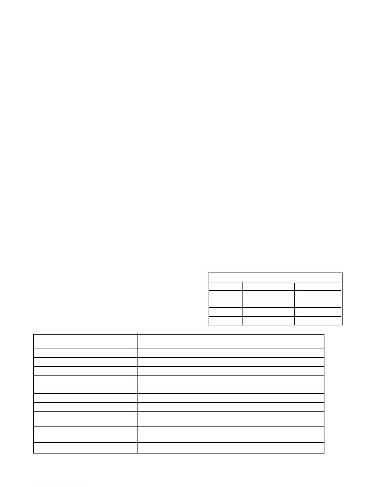
The Model 396P insertion/submersion
sensor with integral cable is offered with
or without a built-in preamplifier
MODEL
396P TUpH INSERTION/SUBMERSION POLYPROPYLENE pH/ORP SENSOR
Page 7
3
MODEL 396P and 396PVP SECTION 1.0
DESCRIPTIONS AND SPECIFICATIONS
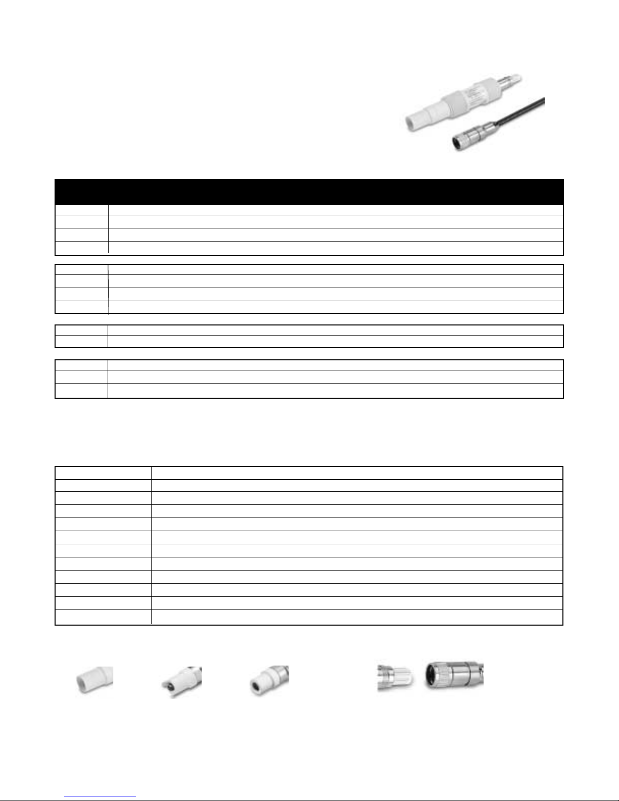
OOppttiioonnaall SSllootttteedd TTiipp
is available on all
hemi bulb sensors,
ordered as option -41
FFllaatt TTiipp
is avail-
able with flat glass
bulb sensors
Examples of all sensing tip offerings
SShhrroouuddeedd TTiipp
is
standard on all
hemi bulb sensors
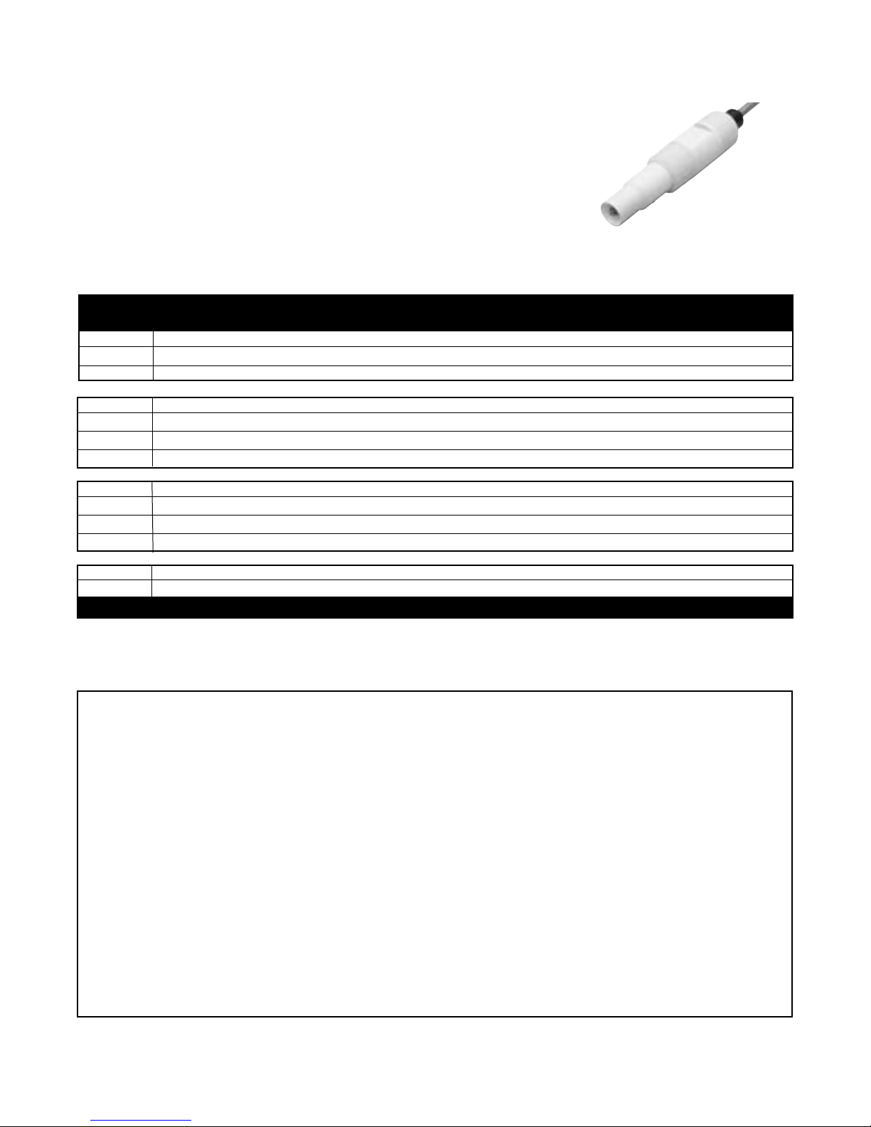
VVaarriiooppooll ccoonnnneeccttoorr
shown with mating variopol
cable receptacle
MODEL
396PVP TUpH INSERTION/SUBMERSION POLYPROPYLENE pH/ORP SENSOR
CODE MEASURING ELECTRODE TYPE (Required Selection)
10 GPLR hemi bulb, General Purpose Low Resistivity (0-14 pH)
12 ORP
13 GPLR flat bulb, General Purpose Low Resistivity (2 - 13 pH)
CODE ANALYZER/TC COMPATIBILITY (Required Selection)
50 For Models 1181 (3K TC)
54 For Models 1054, 1054A, 2054, 2081;2700-Code 02 only (Pt 100 RTD)
55 For Models 54, 3081, 81, 4081 (PT-100 RTD)
CODE OPTIONAL SELECTION
41 Slotted Tip (not available on flat bulb sensors)
PN MATING VP CONNECTOR CABLE
((RReeqquuiirreedd ffoorr aallll nneeww iinnssttaallllaattiioonnss))
23645-06 15 ft.cable with mating VP connector, prepped with BNC on analyzer end
23645-07 15 ft.cable with mating VP connector, prepped without BNC on analyzer end*
The Model 396PVP Sensor has similar features to the Model 396P.
However, the Model 396PVP is offered with the new Variopol (VP)
connector and uses a mating VP cable (purchased separately).
A remote preamplifier must be used with this sensor.
A Variopol cable is required for all new installations. See below
for cable selection.
The Model 396PVP insertion/ submersion sensor with the VP (Variopol) connector
OTHER ACCESSORIES FOR MODELS 396P AND 396PVP
PART DESCRIPTION
22698-00 Preamplifier plug-in for junction box, for Model 1003,
22698-02 Preamplifier plug-in for junction box, for Models 1181, 1050
22698-03 Preamplifier plug-in for junction box, for Models 1054A/B, 2054, 2081
22743-01 Pt100 preamplifier for Model 1181
22744-01 3K Preamplifier for Model 1181
23557-00 Preamplifier for junction box for Models 54, 3081, 81, 4081
9210012 Buffer solution, 4.01 pH, 16 oz
9210013 Buffer solution, 6.86 pH, 16 oz
9210014 Buffer solution, 9.18 pH, 16oz
R508-160Z ORP solution, 460 mv ± 10 at 20°C
12707-00 Jet Spray Cleaner
*For use with connections to Models 1181, 1054/A/B, 2081, 54, 81, 3081, 4081, and remote junction box PN 23555-00.
Page 8

MODEL 396P and 396PVP SECTION 2.0
INSTALLATION
SECTION 2.0
INSTALLATION
2. Do not install the sensor on the horizontal. The
sensor must be 10° off the horizontal to ensure
accuracy.
3. Do not install the sensor upside down.
4. Air bubbles may become trapped in the sensor
end between the glass bulb and the sensor body.
This problem is most commonly encountered in
areas of low flow or during calibration. Shake the
probe while immersed in solution to remove bubbles. This problem can be avoided by ordering the
sensor with the slotted tip (option -41).
In most cases, the pH sensor can simply be installed
as shipped and readings with an accuracy of ± 0.6 pH
may be obtained. To obtain greater accuracy or to verify proper operation, the sensor must be calibrated as
a loop with its compatible analyzer or transmitter.
2.2.1 Flow Through and Insertion Mounting.
Model 396P and 396PVP Sensors have a 1-inch MNPT
process connection at the front of the sensor for
mounting into a 1-1/2 inch tee or the process pipes.
See Figure 2-1 through Figure 2-7 for installation configurations.
NOTE
LARGE PIPE WRENCHES MUST NOT BE USED
TO TIGHTEN THE SENSOR INTO A FLANGE
OR OTHER TYPE OF MOUNTING.
2.2.2 Submersion Mounting. Model 396P and
396PVP Sensors also have a 1 inch MNPT process
connection at the back of the sensor. Utilizing a standard 1 inch union, the sensor may be mounted to a 1
inch SCH 80 CPVC or PVDF standpipe (see Figure 2x). Tapered pipe threads in plastic tend to loosen after
installation. It is therefore recommended that Teflon
1
tape be used on the threads and that the tightness of
the connection be checked frequently to assure that no
loosening has occurred. To prevent rain water or condensation from running into the sensor, a weatherproof
junction box is recommended (see Figure 2-x). The
sensor cable must be run through a protective conduit
for isolation from electrical interference or physical
abuse from the process. The sensor should be
installed within 80° of vertical, with the electrode facing
down. The sensor’ s cable should not be run with power
or control wiring.
1
Teflon is a registered trademark of E.I. du Pont de Nemours & Co.
2.1 UNPACKING AND INSPECTION.
Inspect the outside of the carton for any damage. If damage is detected, contact the carrier immediately. Inspect
the hardware. Make sure all the items in the packing list
are present and in good condition. Notify the factory if
any part is missing. If the sensor appears to be in satisfactory condition, proceed to Section 2.2, Mounting.
NOTE
Save the original packing cartons and materials as most carriers require proof of damage
due to mishandling, etc. Also, if it is necessary to return the sensor to the factory, you
must pack the sensor in the same manner as
it was received. Refer to Section 6.0 for return
instructions. If the sensor is to be stored, the
vinyl boot should be filled with pH buffer solution and replaced on sensor tip until ready to
use.
CAUTION
Buffer solution, in the vinyl boot, may cause
skin or eye irritation.
WARNING
Glass electrode must be wetted at all times (in
storage and in line) to maximize sensor life.
2.2 MOUNTING.
The sensor has been designed to be located in industrial process environments. Temperature and pr essur e
limitations must not be exceeded at any time. A caution label regarding this matter is attached to the sensor. Please do not remove the label. See Figure 2-1.
CAUTION
Internal electrolyte fill solution may cause skin
or eye irritation.
Mounting Guidelines:
1. Shake the sensor in a downward motion to
remove any air bubbles that may be present
inside the tip of the pH glass.
4
Page 9
5
MODEL 396P and 396PVP SECTION 2.0
INSTALLATION
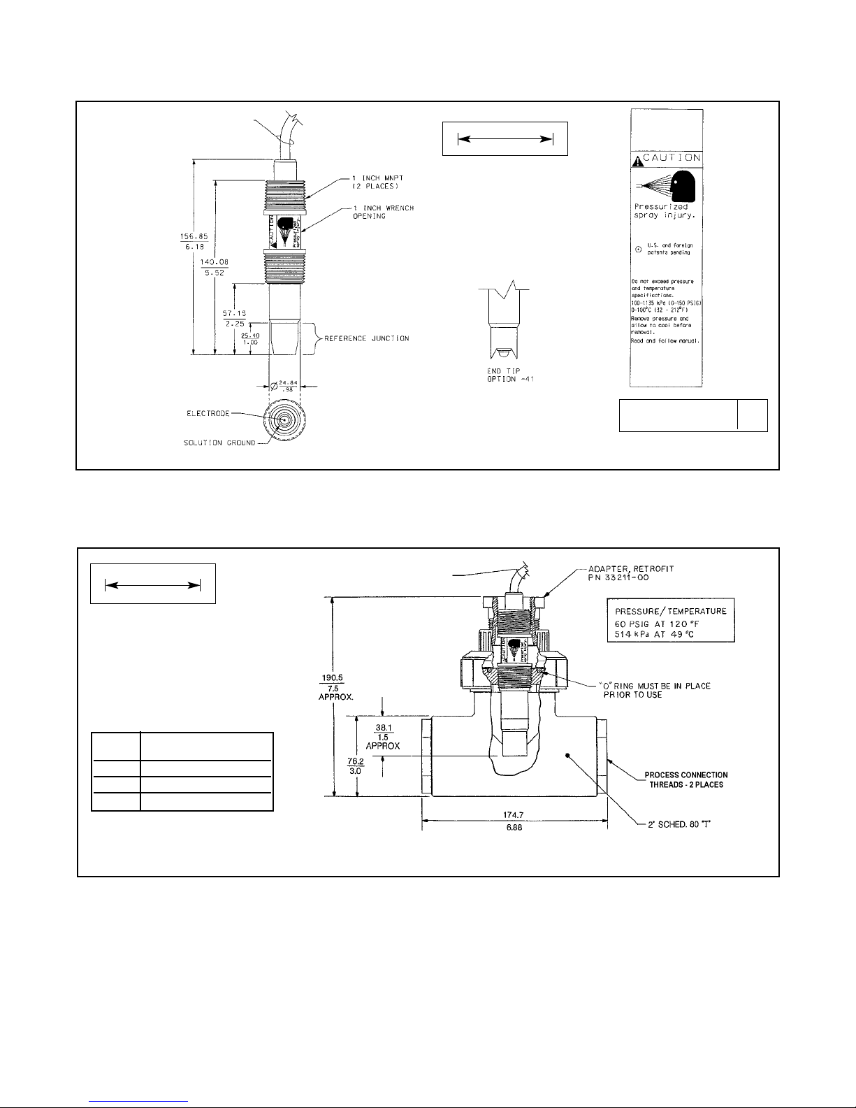
FIGURE 2-1. Dimensional Drawing
DWG. NO. REV.
40396P01 D
MILLIMETER
INCH
FIGURE 2-2. Flow-Through Tee with Adapter (PN 915240-xx*)
MILLIMETER
INCH
xx* Process Connection
Threads
03 3/4 inch
04 1 inch
05 1-1/2 inch
SENSOR CABLE (OR VP CONNECTOR - NOT SHOWN)
SENSOR CABLE
(OR VP CONNECTOR
- NOT SHOWN)
Page 10

MODEL 396P and 396PVP SECTION 2.0
INSTALLATION
FIGURE 2-4. Model 396P with Insertion Mounting Adapter (PN 23242-02).
Not for use with Model 396PVP.
Mounting adapter allows for sensor removal without twisting or
disconnecting interconnecting cable for ease of maintenance.
WHEN INCH AND METRIC DIMS
ARE GIVEN
MILLIMETER
INCH
DWG. NO. REV.
40396P02 A
FIGURE 2-3. Flow-Through and Insertion Installations
1-1/2” PIPE “Y”
1-1/2” X 1”
Reducing
Bushing
1-1/2” X 1”
Reducing
Bushing
1-1/2” X 1”
Reducing
Bushing
1-1/2” Pipe Tee
PN 2002011
1-1/2” Pipe Tee
PN 2002011
PIPE “Y”
INSTALLATION
SHOWN
STRAIGHT
FLOW
SHOWN
FLOW
ANGLE
FLOW
SHOWN
200.0
7.875
121.92
4.80
85.85
3.375
NECK, UNION FITTING (316 SST) 2-5/8 IN.
WRENCH OPENING
INSERTION MOUNTING ADAPTER PN 23242-02
(INCLUDES: PEEK ADAPTER, 304 SST UNION FITTING)
1-1/2 IN. MNPT
2.531.8 ACME THREAD (TYP)
CABLE (OR VP CONNECTOR - NOT SHOWN)
PEEK ADAPTER 1 IN FNPT X 3/4 IN.FNPT
(REVERSIBLE)
NUT, HEX UNION 2 IN.
3 IN.WRENCH OPENING (304 SST)
6
Page 11
MODEL 396P and 396PVP SECTION 2.0
INSTALLATION
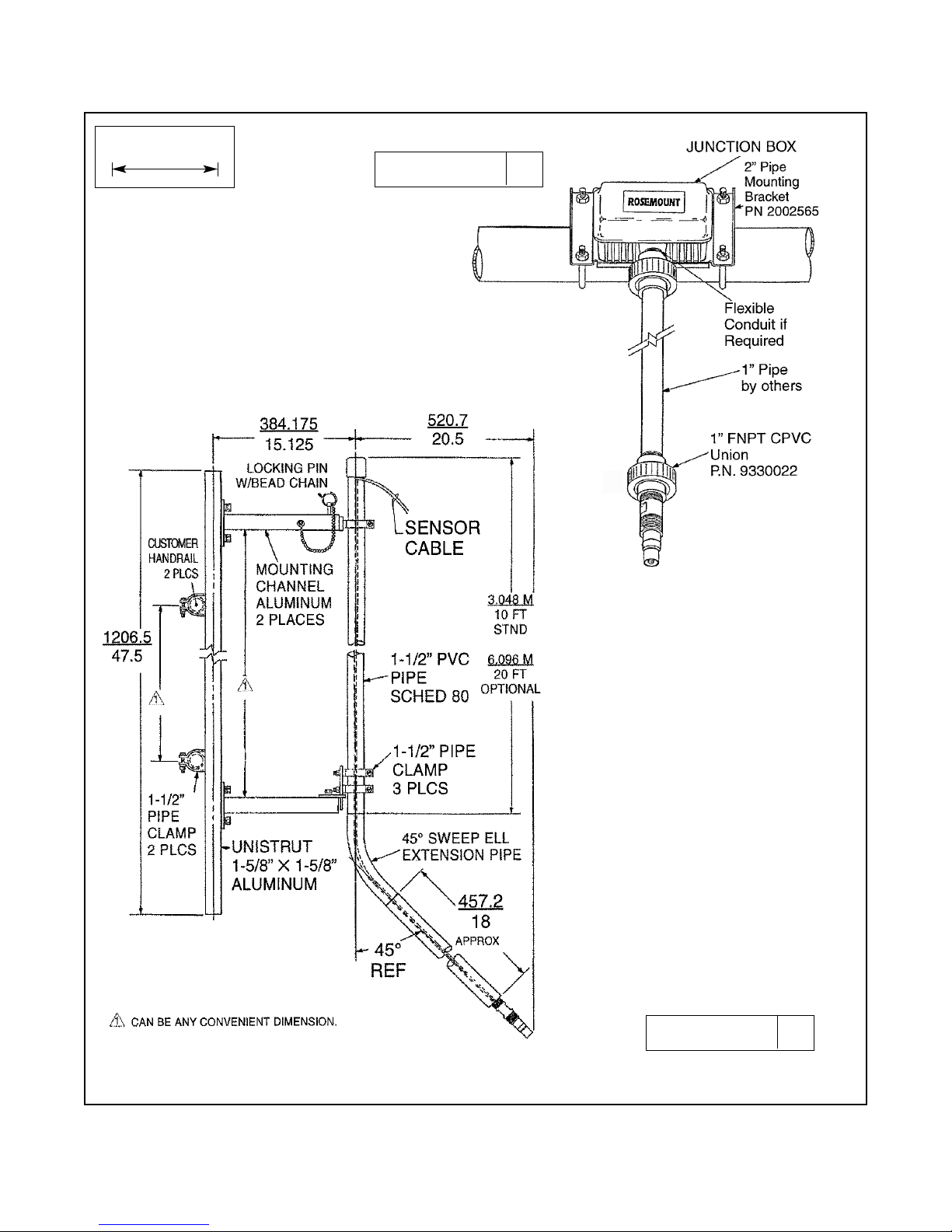
FIGURE 2-5. Submersion Installations
WHEN INCH AND METRIC DIMS
ARE GIVEN
MILLIMETER
INCH
DWG. NO. REV.
40396P04 A
DWG. NO. REV.
40396P03 A
Handrail Mounting
Assembly PN 11275-01
7
Page 12

8
MODEL 396P and 396PVP SECTION 2.0
INSTALLATION
FIGURE 2-6. Low Flow Cell PN 23728-00
MILLIMETER
INCH
FIGURE 2-7. Jet Spray Cleaner PN 12707-00
SENSOR CABLE
(OR VP CONNECTOR
- NOT SHOWN)
Page 13

9
Figures in this section provide the guidelines for wiring
the 396P-01 sensor to various Analyzer/Transmitter
instruments.
To determine which wiring guideline to use, locate the
model number of the sensor to be installed.
1. If the cable needs to be extended, use a high
quality eleven conductor double shielded instrument cable available from Rosemount Analytical.
Refer to Table 3-1 for the appropriate junction box
to use and the corresponding wiring details.
NOTE
If the cable is too long, loop up the excess
cable. If the cable has to be shortened, cut
and terminate each conductor neatly and
make sure that the overall (outermost)
drain wire is not shorted out with either
of the two inner drain wires (shields).
2. Signal cable should be run in a dedicated conduit
(preferably an earth grounded metallic conduit)
and should be kept away from AC power lines.
For your convenience, a wire nut kit is furnished
(in a plastic bag wrapped around the cable).
NOTE
For maximum EMI/RFI protection when
wiring from the sensor to the junction box,
the outer braid of the sensor should be
connected to the outer braided shield of
the extension cable. The outer braid of the
extension cable to the instrument must be
terminated at earth ground or by using an
appropriate metal cable gland fitting that
provides a secure connection to the instrument cable.
Preamplifier Location Analyzer/Transmitter
Sensor Integral to Integral to Remote Interconnect 1054, 1054A, 54, 81, 1055 1181 1050 1003 SCL or Refer to
Model Sensor Analyzer Junction (unprepped 1054B, 2054 3081, 1060 1023 SoluCube Figure
Options
Box (PN) PN) 2081 4081 #
396P-01-()-50 ✓ ✓✓ 3-2
396P-01-()-50 ✓ Ext. box 9200254 ✓✓ 3-2
(22719-02)
396P-01-()-54 ✓✓ 3-3
396P-01-()-54 ✓ Ext. box 9200254 ✓ 3-3
(22719-02)
396P-01-()-55 ✓✓3-5
396P-01-()-55 ✓ Ext. box 9200273 ✓ 3-4
(23550-00)
396P-01-()-55 ✓ 9200273 ✓ 3-6
or 23646-01
TABLE 3-1. Wiring Matrix Guide
MODEL 396P and 396PVP SECTION 3.0
WIRING - MODEL 396P
SECTION 3.0
WIRING — MODEL 396P-01
Page 14

10
MODEL 396P and 396PVP SECTION 3.0
WIRING - MODEL 396P
Wiring. The Model 396P has an optional built-in pre-
amplifier and is offered with a shielded cable. The
cable should be handled carefully and kept dry and
free of corrosive chemicals at all times. Extreme care
should be used to prevent it from being twisted, damaged or scraped by rough, sharp edges or surfaces.
Please refer to Figures 3-1 through 3-6 for wiring
Model 396P-01.
FIGURE 3-1.Wire Functions for Model 396P with and without Preamplifier
DANGER
DO NOT CONNECT SENSOR CABLE TO
POWER LINES. SERIOUS INJURY MAY
RESULT.
Model 396P
Option 01 (with
preamplifier) cable
Model 396P
Option 02 (without
preamplifier) cable
Page 15

11
MODEL 396P and 396PVP SECTION 3.0
WIRING - MODEL 396P
FIGURE 3-2. Wiring Details Model 396P-01-50 for use with and without Junction Box
(PN 22719-02) for Models 1181, 1050, and 1060.
WHEN INCH AND METRIC DIMS
ARE GIVEN
MILLIMETER
INCH
DWG. NO. REV.
40396P15 B
Page 16

12
FIGURE 3-3. Wiring Details Model 396P-01-54 for use with and without Junction Box
(PN 22719-02) for Models 1054, 1054A, 1054B, 2054, 2081, and Extension Cable (9200254).
MODEL 396P and 396PVP SECTION 3.0
WIRING - MODEL 396P
DWG. NO. REV.
40396P13 D
WHEN INCH AND METRIC DIMS
ARE GIVEN
MILLIMETER
INCH
Page 17

13
MODEL 396P and 396PVP SECTION 3.0
WIRING - MODEL 396P
FIGURE 3-4. Wiring Details Model 396P-01-55 for use with Junction Box
(PN 23550-00) for Models 54, 3081, 4081, and 81.
WHEN INCH AND METRIC DIMS
ARE GIVEN
MILLIMETER
INCH
DWG. NO. REV.
40396P08 B
Page 18

14
MODEL 396P and 396PVP SECTION 3.0
WIRING - MODEL 396P
FIGURE 3-5.Wiring Details Model 396P-01-55 for use with Models 54, 81, 3081, and 4081
FIGURE 3-6.Wiring Model 396P-01-( )--55 Sensor to Model 1055-10-22-32 Analyzer
Page 19

Figures 4-1 thru 4-22 provide the guidelines for wiring
the sensor to various Analyzer/T ransmitter instruments.
To determine which wiring guideline to use, locate the
model number of the sensor to be installed.
1. If the cable needs to be extended, use a high quality eleven conductor double shielded instrument
cable available from Rosemount Analytical. Refer
to Table 4-1 to refer to the appropriate junction box
to use and the corresponding wiring details.
NOTE
If the cable is too long, loop up the excess
cable. If the cable has to be shortened, cut
and terminate each conductor neatly and
make sure that the overall (outermost)
drain wire is not shorted out with either of
the two inner drain wires (shields).
2. Signal cable should be run in a dedicated conduit
(preferably an earth grounded metallic conduit)
and should be kept away from AC power lines.
For your convenience, a wire nut kit is furnished
(in a plastic bag wrapped around the cable).
NOTE
For maximum EMI/RFI protection when wiring
from the sensor to the junction box, the outer
braid of the sensor should be connected to
the outer braided shield of the extension
cable. The outer braid of the extension cable
to the instrument must be terminated at earth
ground or by using an appropriate metal cable
gland fitting that provides a secure connection
to the instrument cable.
TABLE 4-1. Wiring Matrix Guide
MODEL 396P and 396PVP SECTION 4.0
WIRING - MODEL 396PVP
SECTION 4.0
WIRING — MODELS 396P-02 AND 396PVP
15
Preamplifier Location Analyzer/Transmitter
Sensor Integral to Integral to Remote Interconnect 1054, 1054A, 54, 81, 1055 1181 1050 1003 SCL or Refer to
Model Sensor Analyzer Junction (unprepped 1054B, 2054 3081, 1060 1023 SoluCube Figure
Options
Box (PN) PN) 2081 4081 #
396P-02-()-55 ✓✓4-3, 4-6,
396PVP-55 4-9
396P-02-()-50 ✓✓4-4
396PVP-50
396P-02-()-50 23309-03 9200254 ✓✓✓ 4-22
396PVP-50
396P-02-()-50 23309-03 9200273 or ✓✓✓ 4-8
396PVP-50 23646-01
396P-02-()-54 23309-04 9200254 ✓ 4-23
396P-02-()-54 23309-04 9200273 or ✓ 4-20
396PVP-54 23646-01
396P-02-()-54 ✓✓ 4-5, 4-18
396PVP-54 4-19
396P-02-()-55 23555-00 9200273 or ✓ 4-7, 4-10
396PVP-55 23646-01 4-12
396P-02-()-54
✓
661-898695
✓
4-14
396PVP-54
4-13
396P-02-54 23309-04 9200273 or
✓
4-11
396PVP-54 23646-01
4-21
396P-02-55
✓✓4-15
396PVP-55 4-16
396P-02-55
✓
9200273 or
✓ 4-17
396PVP-55 23646-01
Page 20

16
MODEL 396P and 396PVP SECTION 4.0
WIRING - MODEL 396PVP
FIGURE 4-1.Wire Functions
for Mating Variopol Cable used
with Model 396PVP
FIGURE 4-2. Connector Pins
and Their Functions
FIGURE 4-3. Wiring Details for Models 396PVP
or 396P-02-55 with Mating Variopol Cable
(PN 23645-07) for use with Model 81
FIGURE 4-4. Wiring Details for Models 396PVP
or 396P-02-50 with Mating Variopol Cable
(PN 23645-07) for use with Model 1181
FIGURE 4-5. Wiring Details for Models 396PVP
or 396P-02-54 with Mating Variopol Cable
(PN 23645-07) for use with Model 2081
FIGURE 4-6. Wiring Details for Models 396PVP
or 396P-02-55 with Mating Variopol Cable
(PN 23645-07) for use with Models 3081 and 4081
Page 21

MODEL 396P and 396PVP SECTION 4.0
WIRING - MODEL 396PVP
FIGURE 4-8. Wiring Details for Models 396PVP
or 396P-02-50 with Mating Variopol Cable
(PN 23645-06) for use with Remote Junction Box
(PN 23309-03) to Model 1181
FIGURE 4-7. Wiring Details for Models 396PVP
or 396P-02-55 with Mating Variopol Cable
(PN 23645-07) for use with Remote Junction Box
(PN 23555-00) to Model 81
FIGURE 4-9. Wiring Details for
Models 396PVP or 396P-02-55 with
Mating Variopol Cable (PN 23645-07)
for use with Model 54
FIGURE 4-10. Wiring Details for Models 396PVP or 396P-02-55
with Mating Variopol Cable (PN 23645-07) for use with Remote
Junction Box (PN 23555-00) to Model 54
17
Page 22

18
MODEL 396P and 396PVP SECTION 4.0
WIRING - MODEL 396PVP
FIGURE 4-12. Wiring Details for Models 396PVP or 396P02-55 with Mating Variopol Cable (PN 23645-07) for use with
Remote Junction Box (PN 23555-00) to Models 3081 & 4081
FIGURE 4-11. Wiring Details for Models 396PVP or 396P-
02-54 with Mating Variopol Cable (PN 23645-06) for use
with Remote Junction Box (PN 23309-04) to Model 2081
FIGURE 4-13. Wiring Details for Models 396PVP or
396P-02-54 with Mating Variopol Cable (PN 23645-07)
for use with Model 2700
FIGURE 4-14. Wiring Details for Models 396PVP or
396P-02-54 with Mating Variopol Cable (PN 23645-07)
for use with Model SCL-(P/Q)
Page 23

MODEL 396P and 396PVP SECTION 4.0
WIRING - MODEL 396PVP
FIGURE 4-15. Wiring Details for Models 396PVP or 396P-02-55 with Mating Variopol Cable (PN 23645-07) for use with Model 1055
FIGURE 4-16. Wiring Model 396P-(02)-( )--54/55-(61) Sensor to Model 1055-01-10-22-32 Analyzer
FIGURE 4-17. Wiring Details for Models 396PVP or 396P-02-55 with Mating Variopol Cable (PN 23645-07)
for use with Remote Junction Box (PN 23557-00) to Model 1055
NOTE:This wiring diagram can also be used for wiring a Model 396P-01.The wire colors and functions for
the extension cable (PN 9200273) are the same as the 396P-01 wire colors and functions.
19
Page 24

20
MODEL 396P and 396PVP SECTION 4.0
WIRING - MODEL 396PVP
FIGURE 4-18. Wiring Details for Models 396PVP
or 396P-02-54 with Mating Variopol Cable
(PN 23645-07) for use with Model 1054
FIGURE 4-19. Wiring Details for Models 396PVP
or 396P-02-54 with Mating Variopol Cable
(PN 23645-06) for use with Models 1054A/B & 2054
FIGURE 4-21. Wiring Details for Models 396PVP or
396P-02-54 with Mating Variopol Cable (PN 23645-06)
for use with Remote Junction Box (PN 23309-04) to
Models 1054A/B and 2054
FIGURE 4-20. Wiring Details for Models 396PVP or 396P-
02-54 with Mating Variopol Cable (PN 23645-06) for use
with Remote Junction Box (PN 23309-04) to Model 1054
Page 25

MODEL 396P and 396PVP SECTION 4.0
WIRING - MODEL 396PVP
FIGURE 4-22. Wiring Details Model 396P-02-50 for use with Junction Box
(PN 23309-03) and
Remote Preamplifier, Extension Cable
(PN 9200254).
DWG. NO. REV.
40396P25 A
FIGURE 4-23. Wiring Details Model 396P-02-54 for use with Junction Box (PN 23309-04) and
Remote Preamplifier (PN 22698-03), Extension Cable (9200254).
DWG. NO. REV.
40396P24 A
21
Page 26

22
1. While obtaining a process solution sample (it is recommended
that the sample is taken close to the sensor), record the pH value
that is shown on the analyzer/transmitter display.
2. Measure and record the pH of the process solution sample with
another temperature compensated, calibrated pH instrument. For
best results, standardization should be performed at the process
temperature.
3. Adjust the analyzer/transmitter value to the standardized value.
5.2 MODEL 396P and 396PVP ORP SENSORS
5.2.1 SENSOR PREPARATION. Most industrial applications have
a number of ORP reactions occurring in sequence or simultaneously. There can be several components that are oxidized or reduced
by the reagents that are used. Theoretically, the ORP potential is
absolute because it is the result of the oxidation-reduction equilibrium. However, the actual measured potential is dependent on many
factors, including the condition of the surface of the ORP platinum
electrode. Therefore, the sensor should be allowed 1-2 hours to
become “conditioned” to the stream when first set-up or after
being cleaned.
5.2.2 ORP CALIBRATION
1. Make a temporar y electrical connection between the sensor and
the instrument.
2. Obtain an ORP standard solution (PN R508-160Z), or a standard
solution can also be made quite simply by adding a few crystals of
quinhydrone to either pH 4 or pH 7 buffer. Quinhydrone is only slightly soluble therefore a few crystals will be required. (Refer to Section
4.3. for an alternate ORP standard solution).
3. Immerse the sensor in the standard solution. Allow 1-2 minutes for
the ORP sensor to stabilize.
4. Adjust the standardize control of the instrument to the solution value
shown in Table 5-1 (below) or on the label of the standard solution.
The resulting potentials, measured with a clean platinum electrode
and saturated KCl/AgCl reference electrode, should be within ±20
millivolts of the value. Solution temperature must be noted to ensure
accurate interpretation of results. The ORP value of saturated quinhydrone solution is not stable over long periods of time. Therefore,
these standards should be made up fresh each time they are used.
5. Remove the sensor from the buffer, rinse and install in the pr ocess.
MODEL 396P and 396PVP SECTION 5.0
START UP AND CALIBRATION
SECTION 5.0
START UP AND CALIBRATION
5.1 MODELS 396P and 396PVP pH SENSORS
5.1.1 SENSOR PREPARATION. Shake down the sensor
to remove any air bubbles that may be present at the tip of
the pH glass bulb. In most cases, the pH sensor can simply
be installed as shipped and readings with an accuracy of ±
0.6 pH may be obtained. To obtain greater accuracy or to
verify proper operation, the sensor must be calibrated as a
loop with its compatible analyzer or transmitter.
5.1.2 pH CALIBRATION. After a temporar y connection is
established between the sensor and the instrument, a buffer
calibration may be performed. Consult appropriate pH/ORP
analyzer or transmitter instruction manual for specific calibration and standardization procedures, or see below for recommended two-point buffer calibration procedure.
Recommended tw
o-point buffer calibration procedure:
Select two stable buffer solutions, preferably pH 4.0 and 10.0
(pH buffers other than pH 4.0 and pH 10.0 can be used as
long as the pH values are at least two pH units apart).
NOTE
A pH 7.0 buffer solution reads a mV value of approximately zero, and pH b uffers read appro ximately 59.1 mV
for each pH unit above or below pH 7.0. Check the pH
buffer manufacturer specifications for millivolt values at
various temperatures since it may aff ect the actual value
of the buffer solution mV/pH value.
1. Immerse sensor in the first buffer solution. Allow sensor
to adjust to the buffer temperature (to avoid errors due to
temperature differences between the buffer solution and
sensor temperature) and wait for reading to stabilize.
Value of buffer can now be acknowledged by
analyzer/transmitter.
2. Once the first buffer has been acknowledged by the analyzer/transmitter, rinse the buffer solution off of the sensor
with distilled or deionized water.
3. Repeat steps 1 and 2 using the second buffer solution.
4. Once the analyzer/transmitter has acknowledged both
buffer solutions, a sensor slope (mV/pH) is established (the
slope value can be found within the analyzer/ transmitter).
5. The slope value should read about 59.1 mV/pH for a new
sensor and will decrease over time to approximately 4749 mV/pH. Once the slope reads below the 47-49 mV/pH
range, a new sensor should be installed to maintain
accurate readings.
Recommended pH Sensor Standar
dization:
For maximum accuracy, the sensor can be standardized
online or with a process grab sample after a buffer calibration
has been performed and the sensor has been conditioned to
the process. Standardization accounts for the sensor junction
potential and other interferences. Standardization will not
change the sensor’s slope but will simply adjust the analyzer’s
reading to match that of the known process pH.
pH 4 Solution pH 7 Solution
Temp °°C 20 25 30 20 25 30
Millivolt Potential 268 264 260 94 87 80
TABLE 5-1. ORP of Saturated Quinhydrone
Solution (In Millivolts)
CAUTION
The solution used during the following check is an acid and
should be handled with care. Follow the directions of the acid
manufacturer. Wear the proper protective equipment. Do not
let the solution come in contact with skin or clothing. If contact with skin is made, immediately rinse with clean water.
Page 27

23
MODEL 396P and 396PVP SECTION 6.0
MAINTENANCE
The Model 396P and 396PVP Sensors require minimum maintenance. The sensor should be kept clean
and free of debris and sediment at all times. The frequency of cleaning by wiping or brushing with a soft
cloth or brush is determined by the nature of the solution being measured. The sensor should be removed
from the process periodically and checked in buffer
solutions.
WARNING
BEFORE REMOVING THE SENSOR, be
absolutely certain that the process pressure is reduced to 0 psig and the
process temperature is lowered to a
safe level!
If the sensor will not calibrate, refer to your analyzer/
transmitter instruction manual for proper test procedures. If it is determined that the sensor has failed, it
should be discarded and replaced.
6.1 AUTOMATIC TEMPERATURE
COMPENSATOR.
The temperature compensator element is temperature sensitive and can be checked with an ohmmeter. Resistance increases with temperature.
The 3K element will read 3000 ohms ± 1% at 25°C
(77°F) and a Pt100 will read 110 ohms. Resistance
varies with temperature for a 3K and Pt100 element
and can be determined according to Table 6-2 or the
following formula:
RT=Ro[l+R1(T-20)]
Where RT = Resistance
T = Temperature in °C
Refer to Table 6-1 for Roand R1values
6.2 MODEL 396P & 396PVP pH SENSORS
4.2.1 ELECTRODE CLEANING. If the electrode is
coated or dirty, clean as follows:
1. Remove the sensor from process.
2. Wipe the glass bulb with a soft, clean, lint free
cloth or tissue. If this does not remove the dirt or
coating, go to Step 3. (Detergents clean oil and
grease; acids remove scale.)
3. Wash the glass bulb in a mild detergent solution
and rinse it in clean water. If this does not clean
the glass bulb, go to Step 4.
SECTION 6.0
MAINTENANCE
CAUTION
The solution used during the following
check is an acid and should be handled
with care. Follow the directions of the acid
manufacturer. Wear the proper protective
equipment. Do not let the solution come in
contact with skin or clothing. If contact
with skin is made, immediately rinse with
clean water.
4. Wash the glass bulb in a dilute 5% hydrochloric
acid solution and rinse with clean water. Soaking
the sensor overnight in the acid solution can
improve cleaning action.
NOTE
Erroneous pH results may result immediately after acid soak, due to reference
junction potential build-up.
Replace the sensor if cleaning does not
restore sensor operation.
TABLE 6-1
Roand R1VALUES FOR TEMPERATURE
COMPENSATION ELEMENTS
Resistance
Temperature °C (Ohms) ±1%
3K Pt100
0 2670 100.0
10 2802 103.8
20 2934 107.7
25 3000 109.6
30 3066 111.5
40 3198 115.4
50 3330 119.2
60 3462 123.1
70 3594 126.9
80 3726 130.8
90 3858 134.6
100 3990 138.5
Temperature
Compensation Element
R
o
R
1
3K 2934 .0045
Pt100 107.7 .00385
TABLE 6-2
TEMPERATURE vs RESISTANCE OF AUTO
T.C. ELEMENTS
Page 28

24
MODEL 396P and 396PVP SECTION 6.0
MAINTENANCE
6.3 MODEL 396P and 396PVP ORP
4.3.1 Platinum Electrode Check. The platinum elec-
trode may be checked as follows: There are three
types of standard solutions which may be used to
check the ORP electrode/transmitter system.
Type 1: A prepared ORP standard solution
(PN R508-160Z)
Type 2: Another type of commonly used ORP standard solution is the saturated quinhydrone solution.
Refer to Section 5.2.
CAUTION
The solution used during the following
check is an acid and should be handled
with care. Follow the directions of the acid
manufacturer. Wear the proper protective
equipment. If contact with skin of clothing
is made, immediately rinse with plenty of
clean water.
Type 3: A third ORP standard solution can be prepared from the following recipe: Dissolve 39.2 grams
of reagent grade ferrous ammonium sulfate, Fe(NH4)
2
(SO4)2• 6H2O and 48.2 grams of reagent grade ferric ammonium sulfate, FeNH4(SO4)2• 12H2O, in
approximately 700 milliliters of water (distilled water is
preferred, but tap water is acceptable). Slowly and
carefully add 56.2 milliliters of concentrated sulfuric
acid. Add sufficient water to bring the total solution
volume up to 1000 ml. This standard ORP solution,
although not as simple to prepare as the quinhydrone
recipe, is much more stable, and will maintain its millivolt value for approximately one year when stored in
glass containers. This solution (ferric/ferrous ammonium sulfate) will produce a nominal ORP of 476 +20 mV
at 25°C when used with a saturated KCl/AgCl reference electrode and platinum measuring electrode.
Some tolerance in mV values is to be expected due to
the rather large liquid reference junction potentials
which can arise when measuring this strongly acidic
and concentrated solution. However, if the measuring
electrodes are kept clean and in good operating condition, consistently repeatable calibrations can be carried out using this standard solution.
6.3.2 Cleaning Platinum Electrode. The electrode
can be restored to normal operation by simply cleaning
the platinum electrode with baking soda. Polish it by rubbing it with a damp paper towel and baking soda until a
bright, shiny appearance is attained.
Page 29

25
MODEL 396P and 396PVP SECTION 7.0
DIAGNOSTICS AND TROUBLESHOOTING
SECTION 7.0
DIAGNOSTICS AND TROUBLESHOOTING
7.1 MODEL 54/81/3081/4081 DIAGNOSTICS AND TROUBLESHOOTING
The Model 54 Analyzer and Models 81 and 3081 Transmitters automatically search for fault conditions that would
cause an error in the measured pH value, as does the Model 1054B pH/ORP Analyzer to a lesser degree. Refer to
the applicable Instruction Manual for a complete description of the analyzer’s fault conditions.
Table 7-1, below , lists the Model 54’s, 4081’s, 3081’s, and 81’s diagnostic messages that indicate a possible sensor problem. A more complete description of the problem and a suggested remedy corresponding to each message is also listed.
DIAGNOSTIC MESSAGE
54
3081/81/4081 DESCRIPTION OF PROBLEM REMEDY
“Calibration Warning” 1. Aged glass. 1. Perform buffer calibration.
2. Sensor not immersed. 2. Be sure electrode measuring tip is in
CALIbrAtE process.
“Cracked glass failure” Broken or cracked glass. Replace sensor.
6LASS fAIL
“High reference impede” 1. Liquid junction coated. 1. Clean sensor; replace if necessary.
2. Reference Cell gel depleted. 2. Replace sensor.
rEF fAIL or rEF WjArn 3. Sensor not immersed. 3. Be sure electrode measuring tip is in
process.
“Input voltage high” pH input shor ted or sensor Check wiring. Replace sensor if
“Input voltage low” miswired. necessary.
“Old glass warning” 1. Glass electrode worn out. 1. Replace sensor.
2. Sensor not immersed. 2. Be sure electrode measuring tip is in
6LaSS WjArn
process.
“Reference offset err” Reference electrode poisoned. Replace sensor.
(offline only)
Std Err
“Ref voltage high” 1. Reference shorted or sensor Check wiring and installation. Replace
“Ref voltage low” miswired. sensor if necessary.
2. Sensor not immersed
“Sensor line open” 1.
Open wire between sensor and analyzer.
1. Check sensor wiring.
2. Interconnecting cable greater than 2. Relocate analyzer.
LInE FAIL 1000 ft.
“Sensor miswired” 1.
Open wire between sensor and analyzer.
1. Check wiring.
2. Bad preamplifier. 2. Replace preamplifier. (Code 02 only)
“Temp error high” 1. Open or shorted RTD. 1. Replace sensor.
“Temp error low” 2. Temperature out of range. 2. Check process temperature.
tEMP H I
tEMP LO
TABLE 7-1. Troubleshooting with Advanced Diagnostics
Page 30

26
7.2 TROUBLESHOOTING WITHOUT ADVANCED DIAGNOSTICS.
Table 7-2, below, lists common problems, causes and remedies typically encountered in process measurement.
Problem Probable Cause Remedy
Meter reads off scale. (Display Defective preamplifier Replace preamplifier (for code 02
reads overrange).
sensors). For code 01, replace sensor.
T.C. element shorted Check T.C. element as instructed
in Section 6.1 and
replace sensor if defective.
Sensor not in process. Sample Make sure sensor is in process with
stream is low or air bubbles are sufficient sample stream (refer to
present. Section 2.0 for installation details).
Open glass electrode Replace sensor.
Reference element open - no contact
Replace sensor.
Display reads between 3 and 6 pH Electrode cracked Replace sensor.
regardless of actual pH of solution
or sample.
Meter or display indication swings T.C. element shorted Check T.C. element as instructed
or jumps widely in AUTO T.C. Mode. in Section 6.1 and replace
sensor if defective.
Span between buffers extremely T.C. element open Check T.C. element as instructed
short in AUTO T.C. Mode. in Section 6.1 and replace sensor
if defective.
Sluggish or slow meter indication Electrode coated Clean sensor as instructed in
for real changes in pH level. Sections 6.2 or Section 6.3.2.
Replace sensor if cracked.
Electrode defective Replace sensor.
Transmitter cannot be standardized. Electrode coated or cracked Clean Sensor as instructed in
Sections 6.2 or Section 6.3.2
Replace sensor if cracked.
Defective preamplifier Replace preamplifier.
Transmitter short spans between Aged glass electrode or high Replace sensor.
two different buffer values. temperature exposure
Electrode coated Clean Sensor as instructed in
Section 6.2 or Section 6.3.2.
Replace sensor if cracked.
Air bubbles trapped in sensor end Shake the sensor in solution. See
between glass bulb and sensor body Section 2.0 for mounting guidelines.
TABLE 7-2.Troubleshooting without Advanced Diagnostics
MODEL 396P and 396PVP SECTION 7.0
TROUBLESHOOTING
Page 31

27
MODEL 396P and 396PVP SECTION 7.0
TROUBLESHOOTING
TABLE 7-3. Model 396P and 396PVP pH/ORP Replacement Parts and Accessories
PN DESCRIPTION QUANTITY
11275-01 Sensor Handrail Mounting Assembly
2002011 Flow Cell, CPVC, 1 inch FNPT
23242-02 Mounting Adapter, Insertion, 1¼-inch MNPT (304 S.S.) X 1” FNPT (PEEK)
23309-03 Junction Box, for remote preamplifier Code-50
23309-04 Junction Box, for remote preamplifier Code-54
23646-01 Cable, Extension (Prepped) for Models 54, 81, 3081, and 4081
23555-00 Junction Box with preamplifier, Models 54, 81, 3081, and 4081 compatible
23557-00 Preamplifier, remote for Junction Box, Models 54, 81, 3081, and 4081 compatible
22698-00 Preamplifier, Plug-in, Model 1003 compatible (for Code 02-50) 1
22698-02 Preamplifier, Plug-in, Models 1181 and 1050 compatible (for Code 02-50) 1
22698-03 Preamplifier, Plug-in, Models 1054, 1054A, 1054B, 2054, and 2081 compatible (for Code 02-54) 1
22719-02 Junction Box, w/o Preamplifier
33081-00 Adapter Insert, PEEK, 1 X 3/4-inch, for 23242-02
7901631 Shroud, PVC
9200254 Cable, 4 conductor, 22 AWG, shielded pair, for 1054/A/B, 2054, and 1181
9200273 Cable, Extension (Unprepped) for Models 54, 81, 3081, and 4081
23645-06 15 ft (4.6 m) cable with mating VP connector with BNC on transmitter end
23645-07 15 ft (4.6 m) cable with mating VP connector with bare wires on transmitter end
9210012 Buffer Solution, 4.01pH, 16 oz 4
9210013 Buffer Solution, 6.86pH, 16 oz 4
9210014 Buffer Solution, 9.18pH, 16 oz 4
9322014 Union, KYNAR
1
9330022 Union, CPVC
9120516 BNC Adapter
915240-04 Tee, Flow-through, 2” PVC, 1” NPT
9550175 O-ring for Mounting Adapter (23242-02)
R508-160Z ORP Standard Solution, 460mV ±10 at 20°C
23550-00 Junction Box with Extension Board, Models 54, 81, 3081, and 4081 compatible
661-898695 Cable 5 Conductor (for Model 2700 only)
Page 32

28
MODEL 396P and 396PVP SECTION 8.0
RETURN OF MATERIAL
SECTION 8.0
RETURN OF MATERIAL
8.1 GENERAL.
To expedite the repair and return of instruments,
proper communication between the customer and
the factory is important. Before returning a product
for repair, call 1-949-863-1181 for a R etur n Materials
Authorization (RMA) number.
8.2 W ARRANTY REP AIR.
The following is the procedure for returning instruments still under warranty:
1. Call Rosemount Analytical for authorization.
2. T o verify warranty, supply the factory sales order
number or the original purchase order number.
In the case of individual parts or sub-assemblies, the serial number on the unit must be supplied.
3. Carefully package the materials and enclose
your “Letter of Transmittal” (see Warranty). If
possible, pack the materials in the same manner as they were received.
4. Send the package prepaid to:
Rosemount Analytical Inc., Uniloc Division
Uniloc Division
2400 Barranca Parkway
Irvine, CA 92606
Attn: Factory Repair
RMA No. ____________
Mark the package: Returned for Repair
Model No. ____
8.3 NON-WARRANTY REPAIR.
The following is the procedure for returning for
repair instruments that are no longer under warranty:
1. Call Rosemount Analytical for authorization.
2. Supply the purchase order number, and make
sure to provide the name and telephone number
of the individual to be contacted should additional information be needed.
3. Do Steps 3 and 4 of Section 8.2.
NOTE
Consult the factory for additional information regarding service or repair.
Page 33

FROM: RETURN BILL TO:
_____________________________ _____________________________ _____________________________
_____________________________ _____________________________ _____________________________
_____________________________ _____________________________ _____________________________
CUSTOMER/USER MUST SUBMIT MATERIAL SAFETY SHEET (MSDS) OR COMPLETE STREAM COMPOSITION, AND/OR
LETTER CERTIFYING THE MATERIALS HAVE BEEN DISINFECTED AND/OR DETOXIFIED WHEN RETURNING ANY PRODUCT,
SAMPLE OR MATERIAL THAT HAVE BEEN EXPOSED TO OR USED IN AN ENVIRONMENT OR PROCESS THAT CONTAINS A
HAZARDOUS MATERIAL ANY OF THE ABOVE THA T IS SUBMITTED TO ROSEMOUNT ANALYTICAL WITHOUT THE MSDS
WILL BE RETURNED TO SENDER C.O.D. FOR THE SAFETY AND HEALTH OF OUR EMPLOYEES. WE THANK YOU IN
ADVANCE FOR COMPLIANCE TO THIS SUBJECT.
SENSOR OR CIRCUIT BOARD ONLY:
(Please reference where from in MODEL / SER. NO. Column)
1. PART NO. _____________________________1. MODEL ____________________________________1. SER. NO.__________________
2. PART NO. _____________________________2. MODEL ____________________________________2. SER. NO.__________________
3. PART NO. _____________________________3. MODEL ____________________________________3. SER. NO.__________________
4. PART NO. _____________________________4. MODEL ____________________________________4. SER. NO.__________________
PLEASE CHECK ONE:
■■ REPAIR AND CALIBRATE ■■ DEMO EQUIPMENT NO. ______________________________
■■ EVALUATION ■■ OTHER (EXPLAIN) ___________________________________
■■ REPLACEMENT REQUIRED? ■■ YES ■■ NO _______________________________________________________
DESCRIPTION OF MALFUNCTION:
__________________________________________________________________________________________________________________
__________________________________________________________________________________________________________________
__________________________________________________________________________________________________________________
WARRANTY REPAIR REQUESTED:
■■ YES-REFERENCE ORIGINAL ROSEMOUNT ANALYTICAL ORDER NO. _______________________________________________
CUSTOMER PURCHASE ORDER NO. ________________________________________________________
■■ NO-PROCEED WITH REPAIRS-INVOICE AGAINST P.O. NO. _________________________________________________________
■■ NO-CONTACT WITH ESTIMATE OF REPAIR CHARGES: LETTER ■■ _________________________________________________
PHONE ■■ ________________________________________________
NAME___________________________________________________________ PHONE______________________________________________
ADDRESS_______________________________________________________________________________________________________________
_____________________________________________________________________ ZIP______________________________________________
RETURN AUTHORITY FOR CREDIT ADJUSTMENT [Please check appropriate box(s)]
■■ WRONG PART RECEIVED ■■ REPLACEMENT RECEIVED
■■ DUPLICATE SHIPMENT REFERENCE ROSEMOUNT ANALYTICAL SALES ORDER NO. _____________
■■ RETURN FOR CREDIT RETURN AUTHORIZED BY: __________________________________________
WARRANTY DEFECT______________________________________________________________________________________________
_________________________________________________________________________________________________________________
24-6047
RETURN OF MATERIALS REQUEST
•IMPORTANT!
This form must be completed to ensure expedient factory service.
R
E
P
A
I
R
S
T
A
T
U
S
R
E
A
S
O
N
F
O
R
R
E
T
U
R
N
C
U
S
T
O
M
E
R
N
O
T
I
C
E
T
O
S
E
N
D
E
R
Rosemount Analytical Inc.
Uniloc Division
2400 Barranca Parkway
Irvine, CA 92606 USA
Tel: 1-800-854-8257
Fax: (949)-474-7250
Page 34

U.S. Field Service
Field Watch Response Center
1-800-654-7768
International
ARGENTINA
Emerson Argentina
Buenos Aires
54 1 780311,
795-9338
AUSTRALIA
Fisher-Rosemount
Pty. Ltd.
Baysw ater, Victoria
(61)(39)721-0200
AUSTRIA
Fisher-Rosemount - AG
Neudorf
(43)(2236)607
BELGIUM
Fisher-Rosemount
N.V./S.A.
Diegem
(32)(2)716-77-11
BRAZIL
Fisher-Rosemount do
Brasil Industria e
Comercio Ltda.
Sorocada
(55)(11)228 3788
CANADA
Rosemount Instruments
Ltd.
Calgary
(800) 268-1151
CHINA
Fisher-Rosemount
Pudong, Shanghai
(86)(215)899-4415
CROATIA
Fisher-Rosemount
Croatia
Zagreb
(385)(1)305 071
CZECH REPUBLIC
Fisher-Rosemount
Praha
(420)(2)81002666-7
DENMARK
Fisher-Rosemount A/S
Alleroed
(45)48-17-03-33
ENGLAND
Fisher-Rosemount
Limited
Bognor Regis
(44)(1243)863-121
FINLAND
Oy Valment-Rosemount
AG
ESPOO
(358)(9)549-541
FRANCE
Fisher-Rosemount S.A.
Lyon
(33)(7)215-98-00
GERMANY
Fisher-Rosemount
GmbH & Co.
D-63549 Hasselroth
(49)(6055)884-0
HUNGARY
Fisher-Rosemount
Budapest
(36)(1)4624001
INDIA
Fisher-Rosemount
(India) Ltd.
New Bombay
(91)(22)762-9191/9200
ITALY
Fisher-Rosemount
Italia s.r.l.
Milan
(11)(39)(39)27021
JAPAN
Fisher-Rosemount Japan
Co., Ltd.
Tokyo
(81)(3)5403-8529
KOREA
Fisher-Rosemount
Korea Ltd.
Seoul
(82)(2)515-2321
MIDDLE EAST
Fisher-Rosemount
Middle-East Dubai,
United Arab Emirates
(971)(4)835235
MALAYSIA
Rosemount Instruments
SDN BHD
Kuala Lumpur
(60)(3)244-5688
MEXICO
Fisher-Rosemount S.A.
de C.V.
Tlalnepantla
(011)(525)728-0885
NEW ZEALAND
Fisher-Rosemount
Auckland
(64)(9)444-1646
NORWAY
Fisher-Rosemount A/S
Porsgrunn
(47)35-55-5600
POLAND
Fisher-Rosemount
Warszawa
(48)(22)857 3856/
647 3865
PORTUGAL
Fisher-Rosemount
Portugal Instrumentos
Limitada
Alfragide
(351)(1)472 88 50
PUERTO RICO
Fisher-Rosemount Inc.
Guaynabo
(787)782-9955, 9956,
or 9957
ROMANIA
Fisher-Rosemount
Bucharest
40 1230 4149/50/59
RUSSIA
Fisher-Rosemount
Moscow
7095 245 86 86
SINGAPORE
Fisher-Rosemount
Singapore
Pte, Ltd
(65)777-8211
SLOVAK REPUBLIC
Fisher-Rosemount scr
Bratislava
42 17 761 973
SPAIN
Fisher-Rosemount S.A.
Madrid
(34)(1)358-91-41
SWEDEN
Fisher-Rosemount AB
Karlstad
(46)(54)19-0090
SWITZERLAND
Fisher-Rosemount AG
Baar
(41)(41)768 62 60
THE NETHERLANDS
Fisher-Rosemount BV
Rijswijk
(31)(70)413-6542
TURKEY
Fisher-Rosemount
Proses Kontrol Ltd.Sri
Istanbul
(90)(216)49 240 42-46
A Worldwide Network of Sales and Service
The Rosemount customer sales and service organization comprises a network of fully equipped support centers strategically located throughout the world. From many of these locations, the Rosemount Group provides support, distribution of finished products, repair facilities, and training for our customers.
Immediate, Reliable Analytical Support
Now there’s a way to quickly get the right answers for your liquid analytical instrumentation
questions: the Analytical Customer Support Center.
Our staff of trained professionals are ready to provide the information you need. If you are
placing an order, verifying delivery, requesting application information, or just want to contact a Rosemount Analytical representative, a toll-free call to 1-800-854-8257 will provide
you with the right people, the right answers, right now.
The right people, the right answers, right now.
Page 35

WARRANTY
Goods and part(s) (excluding consumables) manufactured by Seller are warranted to be free from defects in workmanship and material under normal use and service for a period of twelve (12) months from the date of shipment by
Seller. Consumables, pH electrodes, membranes, liquid junctions, electrolyte, O-rings, etc. are warranted to be free from
defects in workmanship and material under normal use and service for a period of ninety (90) days from date of shipment by Seller. Goods, part(s) and consumables proven by Seller to be defective in workmanship and / or material shall
be replaced or repaired, free of charge, F.O.B. Seller's factory provided that the goods, parts(s), or consumables are
returned to Seller's designated factory, transportation charges prepaid, within the twelve (12) month period of warranty
in the case of goods and part(s), and in the case of consumables, within the ninety (90) day period of warranty . This warranty shall be in effect for replacement or repaired goods, part(s) and consumables for the remaining portion of the period of the twelve (12) month warranty in the case of goods and part(s) and the remaining portion of the ninety (90) day
warranty in the case of consumables. A defect in goods, part(s) and consumables of the commercial unit shall not operate to condemn such commercial unit when such goods, parts(s) or consumables are capable of being renewed,
repaired or replaced.
The Seller shall not be liable to the Buyer, or to any other person, for the loss or damage, directly or indirectly, arising
from the use of the equipment or goods, from breach of any warranty or from any other cause. All other warranties,
expressed or implied are hereby excluded.
IN CONSIDERATION OF THE STATED PURCHASE PRICE OF THE GOODS, SELLER GRANTS ONLY THE ABOVE STATED EXPRESS WARRANTY. NO OTHER WARRANTIES ARE GRANTED INCLUDING, BUT NOT LIMITED TO, EXPRESS
AND IMPLIED WARRANTIES OF MERCHANTABILITY AND FITNESS FOR A PARTICULAR PURPOSE.
RETURN OF MATERIAL
Material returned for repair, whether in or out of warranty, should be shipped prepaid to:
Rosemount Analytical Inc.
Uniloc Division
2400 Barranca Parkway
Irvine, CA 92606
The shipping container should be marked:
Return for Repair
Model
_______________________________
The returned material should be accompanied by a letter of transmittal which should include the following information
(make a copy of the "Return of Materials Request" found on the last page of the Manual and provide the following thereon):
1. Location type of service, and length of time of service of the device.
2. Description of the faulty operation of the device and the circumstances of the failure.
3. Name and telephone number of the person to contact if there are questions about the returned material.
4. Statement as to whether warranty or non-warranty service is requested.
5. Complete shipping instructions for return of the material.
Adherence to these procedures will expedite handling of the returned material and will prevent unnecessary additional
charges for inspection and testing to determine the problem with the device.
If the material is returned for out-of-warranty repairs, a purchase order for repairs should be enclosed.
Page 36

Rosemount Analytical Inc.
Uniloc Division
2400 Barranca Parkway
Irvine, CA 92606 USA
Tel: (949) 863-1181
http://www.RAuniloc.com
© Rosemount Analytical Inc. 2001
Credit Cards for U.S. Purchases Only.
The right people,
the right answers,
right now.
ON-LINE ORDERING NOW
AVAILABLE ON OUR WEB SITE
http://www.RAuniloc.com
UNILOC DIVISION
CUSTOMER SUPPORT CENTER
1-800-854-8257
 Loading...