

Page 1
Quick Start Guide
00825-0100-4811, Rev JF
Rosemount™ 3300 Level Transmitter
Guided Wave Radar
April 2022
Page 2

Quick Start Guide April 2022
Contents
About this guide...........................................................................................................................3
Mount the transmitter head/probe.............................................................................................. 7
Set jumpers and switches........................................................................................................... 17
Connect wiring and power up.....................................................................................................19
Configure................................................................................................................................... 25
Environmental conditions.......................................................................................................... 31
Product certifications................................................................................................................. 32
2 Rosemount 3300 Level Transmitter
Page 3

April 2022 Quick Start Guide
1 About this guide
This start guide provides basic guidelines for the Rosemount 3300 Level
Transmitter. Refer to Rosemount 3300 Level Transmitter Reference Manual
for more instructions. The manual and this Quick Start Guide (QSG) are also
available electronically on Emerson.com/Rosemount.
WARNING
Failure to follow safe installation and servicing guidelines could result in
death or serious injury.
• Ensure only qualified personnel perform installation or service.
• Use the equipment only as specified in this Quick Start Guide and the
Reference Manual. Failure to do so may impair the protection provided
by the equipment.
• Do not perform any service other than those contained in this manual
unless you are qualified.
• Flamepath joints are not for repair. Contact the manufacturer.
Explosions could result in death or serious injury.
• Verify that the operating environment of the transmitter is consistent
with the appropriate hazardous locations specifications. See Product
certifications in this Quick Start Guide.
• In an explosion-proof/flameproof installation, do not remove the
transmitter covers when power is applied to the unit.
• Before connecting a handheld communicator in an explosive
atmosphere, ensure the instruments are installed in accordance with
intrinsically safe or non-incendive field wiring practices.
• To avoid process leaks, only use the O-ring designed to seal with the
corresponding flange adapter.
Electrical shock could cause death or serious injury.
• Avoid contact with the leads and terminals. High voltage that may be
present on leads can cause electrical shock.
• Ensure the mains power to the transmitter is off and the lines to any
other external power source are disconnected or not powered while
wiring the transmitter.
Temperature restrictions apply for Explosion-proof versions. For limits, see
certificate-specific information in the Product certifications chapter in this
document.
Quick Start Guide 3
Page 4

Quick Start Guide April 2022
WARNING
The electronics enclosures are category 2G or 2D equipment. The probes
not covered with plastic and not made of titanium, are category 1G or 1D.
The plastic covered probes or probes made of titanium, are only category 1G
equipment.
Probes with non-conducting surfaces and light metals:
• Probes covered with plastic and/or with plastic discs may generate an
ignition- capable level of electrostatic charge under certain extreme
conditions. Therefore, when the probe is used in a potentially explosive
atmosphere, appropriate measures must be taken to prevent
electrostatic discharge. These probes are not allowed in dust classified
areas.
The following probes do not contain plastic or PTFE material, and are
allowed to be placed in a Dust classified area:
Table 1-1: Probes Containing no Plastic or PTFE Material
Code Material of construction: Process connection/Probe
1 316L SST (EN 1.4404)
2 Alloy C-276 (UNS N10276) plate design if flanged version
3 Alloy 400 (UNS N04400) plate design if flanged version
5 Titanium Gr-1 and Gr-2
9 Duplex 2205 (EN 1.4462/UNS S31803) (plate design if flanged
L Alloy 625 (UNS N06625)
M Alloy 400 (UNS N04400)
H Alloy C-276 (UNS N10276)
D Duplex 2205 (EN 1.4462/UNS S31803)
version)
The Material of Construction Code can be found in the ninth character
position of the transmitter model code (for example
330xxxxx1xxxxxxxx).
4 Rosemount 3300 Level Transmitter
Page 5
Category 2D
Category 1D
Applicable marking:
Probes according to Table 1-1
Ex tb [ia Da] IIIC T85 °C…T450 °C Db
II 1/2 D Ex ia IIIC T20085 °C…T200450 °C Da /
Category 2G
Category 1G
All probes possible
II 1/2 G Ex ia IIC T6…T1 Ga /
Ex db [ia Ga] IIC T6…T1 Gb
Applicable marking:
Category 2D
Category 2D
Probes according to Table 1-1
Applicable marking:
II 2 D Ex tb IIIC T85 °C…T135 °C Db
April 2022 Quick Start Guide
• Probes and flanges containing >7.5 percent magnesium or zirconium are
not allowed in explosive dust atmosphere. Contact your Emerson sales
representative for more information.
Probes and flanges containing light metals:
• When used in category 1/2G installations, probes and flanges containing
titanium or zirconium must be mounted in such a way that sparks from
impact or friction between these parts and steel cannot occur.
Separation element (EPL Ga/Gb, Da/Db):
• The materials of the separation element are > 3 mm stainless steel and a
22 mm bushing filled with 2-part epoxy. The epoxy has a continuous
operating temperature of -55 °C ≤ COT ≤ 130 °C. Under normal operation
Quick Start Guide 5
Page 6

Quick Start Guide April 2022
the separation element is not pressurized or in contact with the process
media.
WARNING
Any substitution of non-authorized parts or repair, other than exchanging
the complete transmitter head or probe assembly, may jeopardize safety
and is prohibited.
• Unauthorized changes to the product are strictly prohibited as they may
unintentionally and unpredictably alter performance and jeopardize
safety. Unauthorized changes that interfere with the integrity of the
welds or flanges, such as making additional perforations, compromise
product integrity and safety. Equipment ratings and certifications are no
longer valid on any products that have been damaged or modified
without the prior written permission of Emerson. Any continued use of
product that has been damaged or modified without the written
authorization is at the customer’s sole risk and expense.
WARNING
Physical access
Unauthorized personnel may potentially cause significant damage to and/or
misconfiguration of end users’ equipment. This could be intentional or
unintentional and needs to be protected against.
Physical security is an important part of any security program and
fundamental to protecting your system. Restrict physical access by
unauthorized personnel to protect end users’ assets. This is true for all
systems used within the facility.
6 Rosemount 3300 Level Transmitter
Page 7
$
April 2022 Quick Start Guide
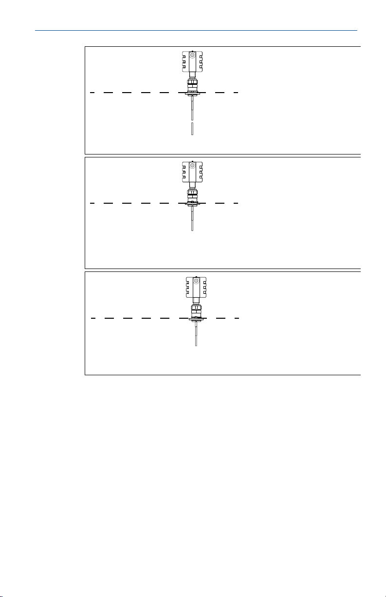
2 Mount the transmitter head/probe
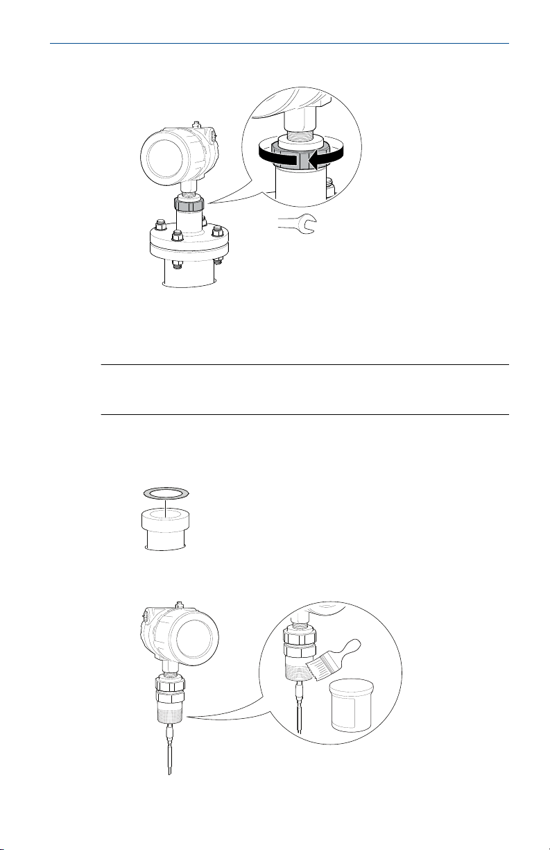
2.1 Tank connection with flange
Prerequisites
Note
PTFE covered probes must be handled carefully to prevent damage to the
coating.
Procedure
1. Place a suitable gasket on top of the tank flange.
Note
Gasket should not be used for PTFE covered probe with protective
plate.
A. PTFE covered probe with protective plate
2. Lower the transmitter and probe with flange into the tank.
Quick Start Guide 7
Page 8
60 mm
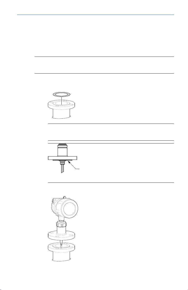
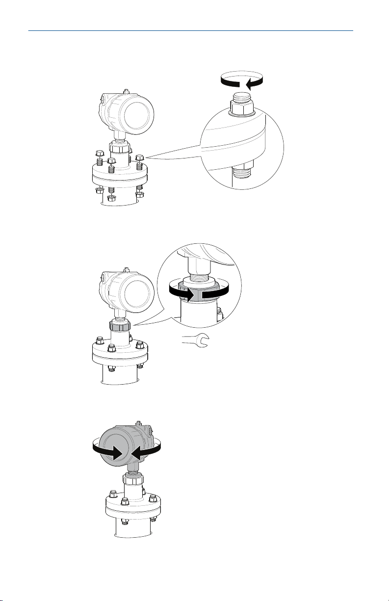
Quick Start Guide April 2022
3. Tighten bolts and nuts with sufficient torque for the flange and
gasket choice.
4. Loosen the nut that connects the transmitter head to the probe
slightly.
5. Rotate the transmitter housing so the cable entries/display face the
desired direction.
8 Rosemount 3300 Level Transmitter
Page 9
60 mm
Torque 30 ft-lb (40 Nm)
April 2022 Quick Start Guide
6. Tighten the nut.
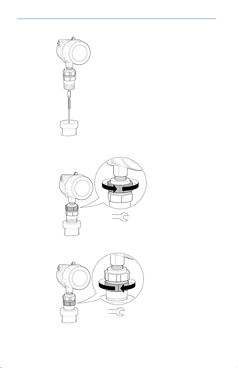
2.2 Threaded tank connection
Prerequisites
Note
PTFE covered probes must be handled carefully to prevent damage to the
coating.
Procedure
1. For adapters with BSPP (G) threads, place a suitable gasket on top of
the tank flange.
2. For adapters with NPT threads, use anti-seize paste or PTFE tape
according to your site procedures.
Quick Start Guide 9
Page 10
60 mm
52 mm / 60 mm
Quick Start Guide April 2022
3. Lower the transmitter and probe into the tank.
4. Loosen the nut that connects the transmitter head to the probe
slightly.
5. Screw the adapter into the process connection.
10 Rosemount 3300 Level Transmitter
Page 11

60 mm
Torque 30 ft-lb (40 Nm)
April 2022 Quick Start Guide
6. Rotate the transmitter housing so the cable entries/display face the
desired direction.
7. Tighten the nut.
Quick Start Guide 11
Page 12
Quick Start Guide April 2022
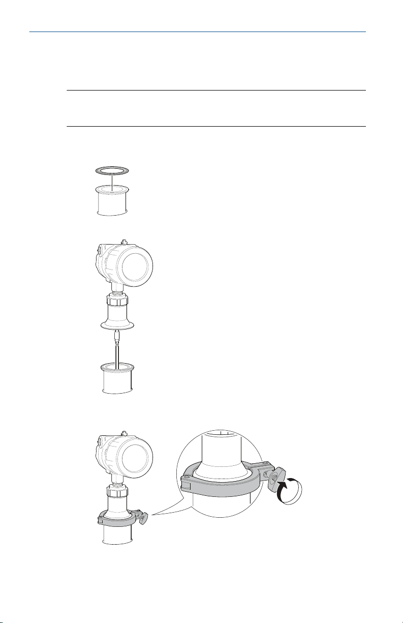
2.3 Tank connection with Tri-Clamp
Prerequisites
Note
PTFE covered probes must be handled carefully to prevent damage to the
coating.
Procedure
1. Place a suitable gasket on top of the tank flange.
2. Lower the transmitter and probe into the tank.
®
3. Tighten the clamp to the recommended torque (see the
manufacturer’s instruction manual).
12 Rosemount 3300 Level Transmitter
Page 13
60 mm
60 mm
Torque 30 ft-lb (40 Nm)
April 2022 Quick Start Guide
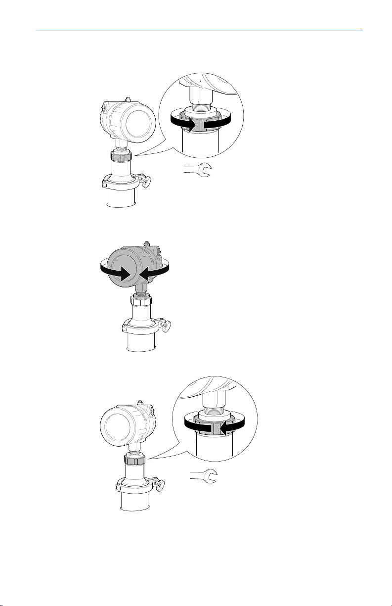
4. Loosen the nut that connects the transmitter head to the probe
slightly.
5. Rotate the transmitter housing so the cable entries/display face the
desired direction.
6. Tighten the nut.
Quick Start Guide 13
Page 14
4X
A
B
4X
Quick Start Guide April 2022
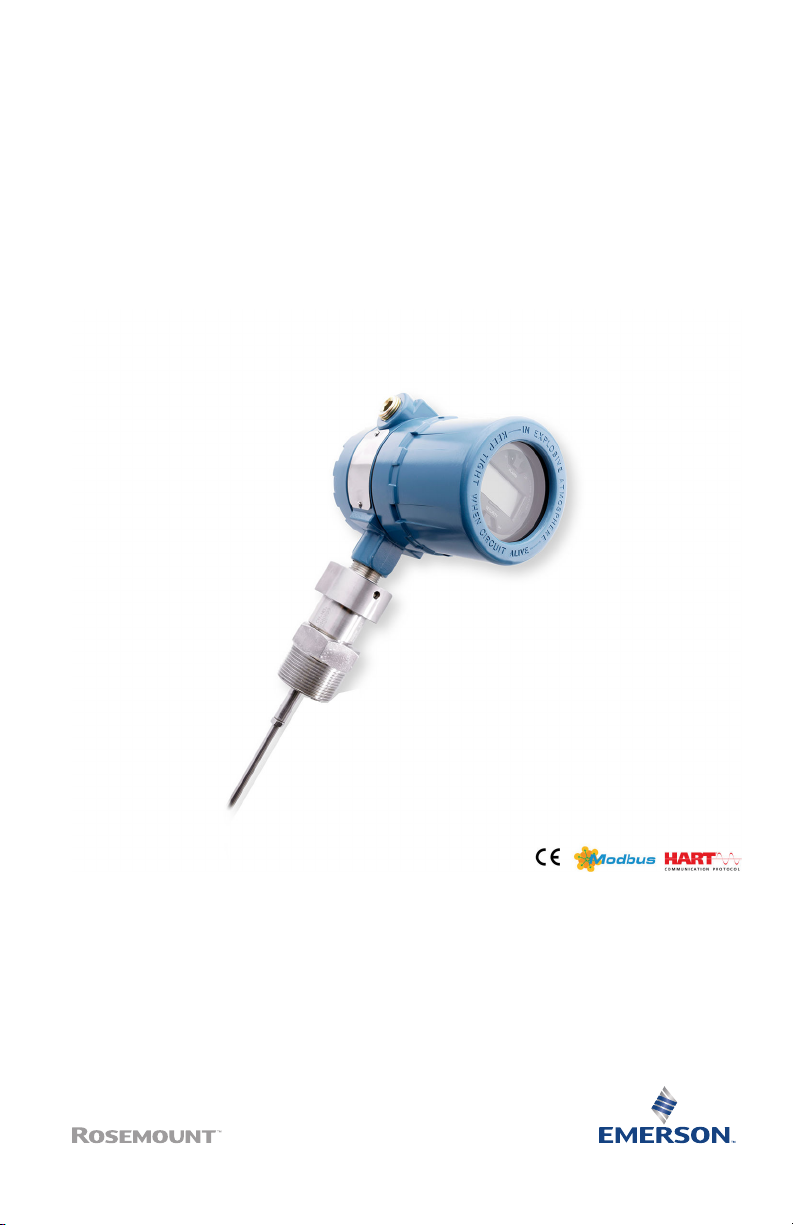
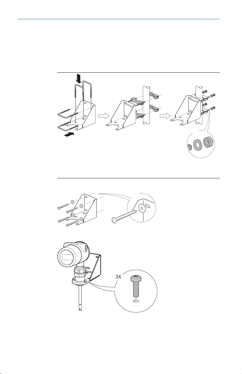
2.4 Bracket mounting
Procedure
1. Mount the bracket to the pipe/wall.
On pipe:
A. Horizontal pipe
B. Vertical pipe
On wall:
2. Mount the transmitter with probe to the bracket.
14 Rosemount 3300 Level Transmitter
Page 15
$
Torque 30 ft-lb (40 Nm)
55 mm
April 2022 Quick Start Guide
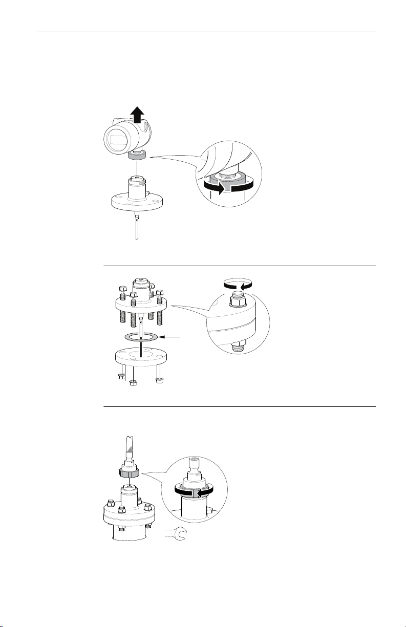
2.5 Install remote housing
Procedure
1. Carefully remove the transmitter.
2. Mount the probe on tank.
A. Gasket
3. Mount the remote connection on the probe.
Quick Start Guide 15
Page 16

4X
A
B
3X
Torque 30 ft-lb (40 Nm)
Quick Start Guide April 2022
4. Mount the bracket to the pipe.
A. Horizontal pipe
B. Vertical pipe
5. Fasten the housing support.
6. Mount the transmitter head.
16 Rosemount 3300 Level Transmitter
Page 17

April 2022 Quick Start Guide
3 Set jumpers and switches
Write Protection must be set after configuration (see Configure).
3.1 Set alarm and write protection on the circuit board
If alarm and security jumpers are not set, the transmitter operates with the
default alarm condition HIGH and Security OFF.
Procedure
1. Remove the cover on the circuit side (see label marked circuit side).
2. To set the 4-20 mA alarm output to LOW, move the alarm switch to
the LOW position.
3. To enable the security write protection feature, move the write
protect switch to the ON position.
4. Replace the cover and tighten securely.
Figure 3-1: Circuit Board
3.2 Set alarm and write protection on the LCD display
Prerequisites
To have the LCD display override the circuit board settings, the write
protection switch on the circuit board needs to be in the OFF position and
the alarm switch on the circuit board needs to be in the HIGH position.
Procedure
1. To set the 4-20 mA alarm output to LOW, place jumper between the
right and center hole position.
2. To enable the security write protection feature, place jumper
between the left and center hole position - ON.
Quick Start Guide 17
Page 18

Quick Start Guide April 2022
Figure 3-2: LCD Display
18 Rosemount 3300 Level Transmitter
Page 19

A
B
D
C
E
April 2022 Quick Start Guide
4 Connect wiring and power up
4.1 Power supply
For HART®, the input voltage is 11-42 V (11-30 V in IS applications, 16-42 V
in Explosion-proof / Flameproof applications). For Modbus®, the input
voltage is 8-30 V.
4.2 Cable selection
The transmitter requires shielded twisted pair wiring (18-12 AWG) suitable
for the supply voltage and, if applicable, approved for use in hazardous
areas.
4.3 Cable/conduit entries
The electronics housing has two entries for ½-14 NPT. Optional M20×1.5
and PG 13.5 adapters are also available. The connections are made in
accordance with local or plant electrical codes.
Make sure that unused ports are properly sealed to prevent moisture or
other contamination from entering the terminal block compartment of the
electronics housing.
Note
Remove any orange caps that may be attached. Use the enclosed metal plug
to seal the unused port.
Figure 4-1: Electronics Housing
A. Cable Entry: ½-14 NPT
Optional adapters: M20, PG13.5
B. Radar electronics
C. Dual compartment housing
D. Flanged process connections
E. Threaded process connections
Quick Start Guide 19
Page 20

A
B
C
D
G
H
E
F
Quick Start Guide April 2022
4.4 Wiring diagram
Figure 4-2: Non-Intrinsically Safe HART® Output
A. Rosemount 3300 Level Transmitter
B. Handheld communicator
C. Load resistance = 250 Ω
D. Power supply
E. HART modem
F. PC
G. Maximum voltage: Um = 250 V
H. HART: Un = 42.4 V
Note
Rosemount 3300 Level Transmitters with Flameproof/Explosion-proof HART
Output have a built-in barrier; no external barrier needed.
20 Rosemount 3300 Level Transmitter
Page 21

A
B
H
G
C
D
E
F
April 2022 Quick Start Guide
Figure 4-3: Intrinsically Safe HART Output
A. Rosemount 3300 Level Transmitter
B. Handheld communicator
C. RL= 250 Ω
D. Power supply
E. HART modem
F. PC
G. DCS
H. Approved IS barrier
IS Parameters: Ui = 30 V, Ii = 130 mA, Pi = 1 W, Li = Ci = 0
Quick Start Guide 21
Page 22

C
F G
B
A
D
E C
H
Quick Start Guide April 2022
Figure 4-4: Non-intrinsically Safe Modbus® Output
A. “A” line
B. “B” line
C. 120 Ω
D. Power supply
E. RS485 Bus
F. HART +
G. HART H. If the unit is the last transmitter on the bus, a 120 Ω termination resistor
is required.
Note
Rosemount 3300 Level Transmitters with Flameproof/Explosion-proof
Modbus Output have a built-in barrier; no external barrier needed.
22 Rosemount 3300 Level Transmitter
Page 23

C
B
A
C
B
A
April 2022 Quick Start Guide
4.5 Load limitations
For HART® communication, a minimum loop resistance of 250 Ω is required.
Maximum loop resistance is determined by the voltage level of the external
power supply, as given by the following diagrams:
Figure 4-5: Non-Hazardous Installations
A. Loop Resistance (Ohms)
B. External Power Supply Voltage (Vdc)
C. Operating region
Figure 4-6: Intrinsically Safe Installations
A. Loop Resistance (Ohms)
B. External Power Supply Voltage (Vdc)
C. Operating region
Quick Start Guide 23
Page 24

C
B
A
Quick Start Guide April 2022
Figure 4-7: Explosion-proof/Flameproof Installations
A. Loop Resistance (Ohms)
B. External Power Supply Voltage (Vdc)
C. Operating region
Note
For the Explosion-proof/Flameproof installations the diagram is only valid if
the HART load resistance is at the + side, otherwise the load resistance value
is limited to 300 Ω.
4.6 Connect the transmitter
Procedure
1. Make sure the housing is grounded according to Hazardous
Locations Certifications, national and local electrical codes.
Grounding is essential for Hazardous Location safety (even for
Flameproof/Explosion Proof versions). A ground cable with a crosssectional area of ≥ 4 mm² must be used.
2. Verify that the power supply is disconnected.
3. Remove the cover on the terminal side (see label marked field
terminals).
4. Pull the cable(s) through the cable gland/conduit.
For Explosion-proof / Flameproof installations, only use cable glands
or conduit entry devices certified Explosion-proof or Flameproof (Ex d
llC (gas) or Ex t lllC (dust)).
5. Connect the cable wires (see Wiring diagram).
6. If applicable, use the enclosed metal plug to seal any unused port.
7. Replace the cover and tighten.
24 Rosemount 3300 Level Transmitter
8. Tighten the cable gland.
9. Connect the power supply.
Page 25

April 2022 Quick Start Guide
5 Configure
If the transmitter is pre-configured at the factory, this section is only
necessary to change or verify the settings.
Configuration of the Rosemount 3300 Level Transmitter can be done either
with a handheld communicator, the AMS Device Manager, or Radar
Configuration Tools (RCT). If using the Radar Configuration Tools, a HART
modem is required.
5.1 Installing the Radar Configuration Tools (RCT) software
To install the RCT software:
Procedure
1. Insert the installation CD into your CD-ROM drive.
2. Follow the instructions.
Need help?
If the installation program does not automatically start, run
Setup.exe from the CD.
5.2 Starting RCT
®
Prerequisites
For optimum performance set COM Port Buffers to 1. Refer to the
Rosemount 3300 Level Transmitter Reference Manual for more instructions.
Procedure
Select Programs → Rosemount → RCT.
Need help?
The Help function of the RCT can be reached from the menu or by pressing
the F1 key.
Quick Start Guide 25
Page 26

Quick Start Guide April 2022
5.3 Configuration using the Wizard
Configuration of a Rosemount 3300 Level Transmitter can be done using the
installation Wizard for detailed guidance.
Procedure
1. Make sure that the Tools Bar is open (Project Bar is ticked within
View). Then select the Wizard icon or select the View → Wizard
menu option.
2. Select the Start button and follow the instructions.
5.4 Configuration using the Setup Function
If you are already familiar with the configuration procedure, or if you want to
change settings, you may use the setup function.
Procedure
1. Make sure that the Tools Bar is open (Project Bar is ticked within
View). Then select the Setup icon or select the View → Setup menu
option.
2. Select the appropriate tab:
• Info (information about the device)
• Basics
• Output
• Tank Config
• Volume (specification of tank geometry for volume calculations)
• LCD (display panel settings)
• Signal Quality Metrics (for activating/de-activating and display of
signal quality metrics, available with the DA1 option)
3. To load the parameters configured in the transmitter into the dialog
window, click the Receive Page button.
4. To load any parameter changes back to the transmitter, click the
Send Page button.
5.4.1 Setup - Basics
Units
Length, volume, and temperature units can be set. Units are used wherever
measurement and configuration data occur.
26 Rosemount 3300 Level Transmitter
Page 27

April 2022 Quick Start Guide
5.4.2 Setup - Output
Range values
The Lower Range value = 4 mA value
The Upper Range value = 20 mA value
The 4-20 mA range must not include the upper or lower Transition Zone.
(1)
Variable assignment
Rosemount 3301 available measuring parameters: Level, Distance to Level,
Total Volume. For fully immersed probe: Interface Level and Interface
Distance.
Rosemount 3302 available measuring parameters: Level, Distance to level,
Total Volume, Interface Level, Interface Distance, and Upper Product Layer
Thickness.
In the Primary Variable field, the measuring parameter is entered for the
analog signal.
More variables can be assigned if the superimposed digital HART® signal or a
HART Tri-loop™ is used.
(1)
See the Rosemount 3300 Level Transmitter Reference Manual.
Quick Start Guide 27
Page 28

Quick Start Guide April 2022
Modbus® setup
If the transmitter has the Modbus option, configuration of the
communication parameters can be set.
28 Rosemount 3300 Level Transmitter
Page 29

April 2022 Quick Start Guide
5.4.3 Setup - Tank Config
Geometry
See tank picture in window.
• Set Reference Gauge Height
• Set Upper Null Zone (if needed)
• Set Mounting Type
• Set Diameter (if Mounting Type is Nozzle or Pipe/Chamber)
• Set Nozzle Height (if Mounting Type is Nozzle)
Probe
• Set Probe Type (This parameter is pre-configured at factory.)
• Set Probe Length (This parameter is pre-configured at factory. The probe
length needs to be changed if the probe is cut in field.)
• Set Probe Angle
• If Remote Housing is mounted, set the Remote Housing length (setting
not available in DD/DTM™)
Miscellaneous settings
• Set Vapor Dielectric value (if needed)
• Set Upper Product Dielectric value (interface measurements only)
Quick Start Guide 29
Page 30

Quick Start Guide April 2022
5.5 Additional configuration to fine-tune performance
To fine-tune the transmitter’s performance, it is recommended the Trim
Near Zone function be executed after configuration is finished.
For detailed information on how to trim the near zone, see the Rosemount
3300 Level Transmitter Reference Manual.
30 Rosemount 3300 Level Transmitter
Page 31

A
B
April 2022 Quick Start Guide
6 Environmental conditions
6.1 Ambient temperature limits (for use in explosive atmospheres)
Explosion-proof/Flame-proof version: -58 °F (-50 °C) ≤ Ta ≤ +167 °F (+75 °C)
Intrinsically safe version: -58 °F (-50 °C) ≤ Ta ≤ +158 °F (+70 °C)
National deviations may apply, see Product certifications.
6.2 Process temperature restrictions
When the Rosemount 3300 is installed in high temperature applications,
consider the maximum ambient temperature. Tank insulation should not
exceed 4 in. (10 cm).
Figure 6-1 shows the maximum ambient temperature vs. process
temperature.
Figure 6-1: Ambient Temperature vs. Process Temperature
A. Ambient temperature °F (°C)
B. Process temperature °F (°C)
6.3
Quick Start Guide 31
Pressure limits
For pressure limits, see the Rosemount 3300 Level Transmitter Reference
Manual.
Page 32

Quick Start Guide April 2022
7 Product certifications
Rev 4.22
7.1 European directive information
A copy of the EU Declaration of Conformity can be found in the section EU
Declaration of Conformity. The most recent revision of the EU Declaration of
Conformity can be found at Emerson.com/Rosemount.
7.2 Ordinary location certification
As standard, the transmitter has been examined and tested to determine
that the design meets the basic electrical, mechanical, and fire protection
requirements by a nationally recognized test laboratory (NRTL) as accredited
by the Federal Occupational Safety and Health Administration (OSHA).
Pollution Degree: 2
Overvoltage Category: II
In Canada: The power to this equipment must be supplied by a source that is
categorized as “CLASS 2” and “SELV” as specified in the Canadian Electrical
Code, C22.1 and the National Electrical Code NFPA 70.
7.3 Installing equipment in North America
The US National Electrical Code® (NEC) and the Canadian Electrical Code
(CEC) permit the use of Division marked equipment in Zones and Zone
marked equipment in Divisions. The markings must be suitable for the area
classification, gas, and temperature class. This information is clearly defined
in the respective codes.
7.4
USA
7.4.1 E5 Explosionproof (XP), Dust-Ignitionproof (DIP)
Certificate
Standards
Markings
32 Rosemount 3300 Level Transmitter
FM 3013394
FM Class 3600 – 2011; FM Class 3610 – 2010; FM Class
3611 – 2004; FM Class 3615 – 2006; FM Class 3810 –
2005; ANSI/ISA 60079-0 – 2009; ANSI/ISA 60079-11 –
2009; ANSI/NEMA 250 – 1991; ANSI/IEC 60529 – 2004
XP CL I, DIV 1, GP B, C, D; DIP CLII/III, DIV 1, GP E, F, G; T5
Ta=85°C; Type 4X/IP66
Page 33

April 2022 Quick Start Guide
Specific Conditions for Safe Use (X):
1. Potential Electrostatic Charging Hazard – The enclosure contains
non-metallic material. To prevent the risk for electrostatic sparking
the plastic surface should only be cleaned with a damp cloth.
2. WARNING – The apparatus enclosure contains aluminum and is
considered to constitute a potential risk of ignition by impact or
friction. Care must be taken into account during installation and use
to prevent impact or friction.
7.4.2 I5 Intrinsic Safety (IS), Nonincendive (NI)
Certificate
Standards
FM 3013394
FM Class 3600 – 2011; FM Class 3610 – 2010; FM Class
3611 – 2004; FM Class 3615 – 2006; FM Class 3810 –
2005; ANSI/ISA 60079-0 – 2009; ANSI/ISA 60079-11 –
2009; ANSI/NEMA 250 – 1991; ANSI/IEC 60529 – 2004
Markings
IS CL I, DIV 1, GP A, B, C, D, E, F, G in accordance with
control drawing 9150077-944; IS (Entity) CL I, Zone 0,
AEx IA IIC T4 in accordance with control drawing
9150077-944, NI CL I, DIV 2, GP A, B, C, D, T4a Ta=70 °C;
Suitable for use in CL II/III DIV 2, GP A, B, C, D, T4a Ta=70
°C; Type 4X/IP66
Specific Conditions for Safe Use (X):
1. Potential Electrostatic Charging Hazard – The enclosure contains
non-metallic material. To prevent the risk for electrostatic sparking
the plastic surface should only be cleaned with a damp cloth.
2. WARNING – The apparatus enclosure contains aluminum and is
considered to constitute a potential risk of ignition by impact or
friction. Care must be taken into account during installation and use
to prevent impact or friction.
Entity parameters HART 30 V 130 mA 1 W 0 nF 0 mH
U
i
I
i
P
i
C
i
L
i
7.5 Canada
7.5.1 E6 Explosionproof, Dust-Ignitionproof
Certificate
Standards
Quick Start Guide 33
CSA02CA1250250X
CSA C22.2 No.0-M91, CSA C22.2 No.25-1966 (R2009),
CSA C22.2 No.30-M1986 (R2012), CSA C22.2 No.94M91, CSA C22.2 No.142-M1987, CAN/CSA-C22.2 No.
Page 34

Quick Start Guide April 2022
60079-0:15, CAN/CSA-C22.2 No. 60079-11:14, CSA
C22.2 No. 213-M1987 (R2013), CAN/CSA C22.2 No.
60529:05
Markings
CL I, Div.1, GP C, D;
CL II, Div.1 & 2, GP G & COAL DUST;
CL III, Div.1 T4, MAX. AMB. TEMP. +85°C
HAZ. LOC. CL I, Div.2, GP A, B, C, D
T4, MAX. AMB. TEMP. +70°C
In ambient temperatures above 60 °C, use wire or cable
rated for 90 °C minimum.
À des températures ambiantes supérieures à 60 °C,
utilisez un fil ou un câble conçu pour 90 °C minimum.
Specific Conditions for Safe Use (X):
1. The enclosure may be made of aluminum alloy and given a protective
polyurethane paint finish; however, care should be taken to protect it
from impact or abrasion if located in zone 0.
2. The probes may contain plastic materials greater than 4cm² or be
coated with plastic and these can present an electrostatic risk if
rubbed or placed in a fast moving air flow.
3. The probes may contain light alloys which can present a risk from
frictional ignitions. Care should be taken to protect them from
mechanical impact or friction during use or installation.
7.5.2 I6 Intrinsically Safe and Non-Incendive Systems
Certificate
Standards
Markings
34 Rosemount 3300 Level Transmitter
CSA02CA1250250X
CSA C22.2 No.0-M91, CSA C22.2 No.25-1966 (R2009),
CSA C22.2 No.30-M1986 (R2012), CSA C22.2 No.94M91, CSA C22.2 No.142-M1987, CAN/CSA-C22.2 No.
60079-0:15, CAN/CSA-C22.2 No. 60079-11:14, CSA
C22.2 No. 213-M1987 (R2013), CAN/CSA C22.2 No.
60529:05
CL I, DIV 1, GP A, B, C, D, T4 see installation drawing
9150077-945; Non-Incendive Class III, DIV 1, Haz-loc CL
I DIV 2, GP A, B, C, D, Maximum Ambient Temperature
+70 °C, T4, Type 4X/IP66
Page 35

April 2022 Quick Start Guide
Specific Conditions for Safe Use (X):
1. The equipment is not capable of withstanding the 500V test as
defined in EN 60079-11. This must be considered in any installation.
2. The enclosure may be made of aluminum alloy and given a protective
polyurethane paint finish; however, care should be taken to protect it
from impact or abrasion if located in zone 0.
3. The probes may contain plastic materials greater than 4cm² or be
coated with plastic and these can present an electrostatic risk if
rubbed or placed in a fast moving air flow.
4. The probes may contain light alloys which can present a risk from
frictional ignitions. Care should be taken to protect them from
mechanical impact or friction during use or installation.
7.6 Europe
7.6.1 E1 ATEX Flameproof
Certificate
Standards
KEMA 01ATEX2220X
EN IEC 60079-0:2018, EN 60079-1:2014, EN
60079-11:2012, EN 60079-26:2015, IEC
60079-26:2021, EN 60079-31:2014
Markings
II 1/2 G Ex ia IIC T6...T1 Ga / Ex db [ia Ga] IIC T6...T1
Gb
II 1/2 D Ex ia IIIC T
85 °C...T
200
450 °C Da / Ex tb [ia Da]
200
IIIC T85 °C...T450 °C Db
II 2 D Ex tb IIIC T85 °C...T135 °C Db
Ambient
temperature
range
-50 °C to +75 °C
-40 °C to +75 °C with a minimum process temperature
of -196 °C
Specific Conditions for Safe Use (X):
1. On application of the transmitter with plastic covered probes, in an
explosive gas atmosphere, precaution shall be taken to avoid danger
of ignition due to electrostatic charges on the probe.
2. On application of the transmitter in an explosive dust atmosphere,
the transmitter shall be installed in such a way that the risk from the
electrostatic discharges and propagating brush discharges caused by
rapid flow of dust at the label is avoided.
3. For probes and flanges containing light metals, an ignition hazard
due to impact or friction needs to be avoided according to EN
60079-0 clause 8.3, when used as EPL Ga/Gb equipment.
Quick Start Guide 35
Page 36

Quick Start Guide April 2022
4. Conditions which may adversely affect the material of the partition
wall shall be avoided, see instructions for details.
Temperature class /
Maximum surface
temperature
T6 / T 85 °C +75 °C +75 °C
T5 / T 100 °C + 90 °C +75 °C
T4 / T 135 °C +125 °C +75 °C
T3 / T 200 °C + 190 °C +75 °C
T2 / T 300 °C +285 °C +65 °C
T1 / T 450 °C + 400 °C +55 °C
7.6.2 I1 ATEX Intrinsic Safety
Certificate
Standards
Markings
Specific Conditions for Safe Use (X):
1. The equipment is not capable of withstanding the 500V test as
defined in EN60079-11. This must be considered in any installation.
2. The enclosure is made of aluminium alloy and given a protective
polyurethane paint finish; however, care should be taken to protect it
from impact or abrasion if located in zone 0.
BAS02ATEX1163X
EN IEC 60079-0:2018, EN 60079-11:2012
II 1G Ex ia IIC T4 Ga (-50°C ≤ Ta ≤ +70°C)
Maximum process
temperature
Maximum ambient
temperature
3. The probes may contain plastic materials greater than 4cm² or be
coated with plastic and these can present an electrostatic risk if
rubbed or placed in a fast moving air flow.
4. The probes may contain light alloys which can present a risk from
frictional ignitions. Care should be taken to protect them from
mechanical impact during use or installation.
Entity parameters HART 30 V 130 mA 1 W 0 nF 0 mH
36 Rosemount 3300 Level Transmitter
U
i
I
i
P
i
C
i
L
i
Page 37

April 2022 Quick Start Guide
7.7 International
7.7.1 E7 IECEx Flameproof
Certificate
Standards
IECEx DEK 12.0015X
IEC 60079-0:2017, IEC 60079-1:2014, IEC
60079-11:2011; IEC 60079-26:2021, IEC
60079-31:2013
Markings
Ex ia IIC T6…T1 Ga / Ex db [ia Ga] IIC T6…T1 Gb
Ex ia IIIC T
85 °C…T
200
450 °C Da / Ex tb [ia Da] IIIC
200
T85 °C…T450 °C Db
Ex tb IIIC T85 °C…T135 °C Db
Ambient
temperature
range
-50 °C to +75 °C
-40 ºC to +75 ºC with a minimum process temperature
of -196 °C
Specific Conditions for Safe Use (X):
1. On application of the transmitter with plastic covered probes, in an
explosive gas atmosphere, precaution shall be taken to avoid danger
of ignition due to electrostatic charges on the probe.
2. On application of the transmitter in an explosive dust atmosphere,
the transmitter shall be installed in such a way that the risk from
electrostatic discharges and propagating brush discharges caused by
rapid flow of dust at the label is avoided.
3. For probes and flanges containing light metals, an ignition hazard
due to impact or friction needs to be avoided according to IEC
60079-0 clause 8.3, when used as EPL Ga/Gb equipment.
4. Conditions which may adversely affect the material of the partition
wall shall be avoided, see instructions for details.
Temperature class /
Maximum surface
temperature
T6 / T 85 °C +75 °C +75 °C
T5 / T 100 °C + 90 °C +75 °C
T4 / T 135 °C +125 °C +75 °C
T3 / T 200 °C + 190 °C +75 °C
T2 / T 300 °C +285 °C +65 °C
T1 / T 450 °C + 400 °C +55 °C
Quick Start Guide 37
Maximum process
temperature
Maximum ambient
temperature
Page 38

Quick Start Guide April 2022
7.7.2 I7 IECEx Intrinsic Safety
Certificate
Standards
Markings
IECEx BAS 12.0062X
IEC 60079-0:2017, IEC 60079-11:2011
Ex ia IIC T4 Ga (-50°C ≤ Ta ≤ +70°C)
Specific Conditions for Safe Use (X):
1. The equipment is not capable of withstanding the 500V test as
defined in EN60079-11. This must be considered in any installation.
2. The enclosure is made of aluminium alloy and given a protective
polyurethane paint finish; however, care should be taken to protect it
from impact or abrasion if located in zone 0.
3. The probes may contain plastic materials greater than 4cm² or be
coated with plastic and these can present an electrostatic risk if
rubbed or placed in a fast moving air flow.
4. The probes may contain light alloys which can present a risk from
frictional ignitions. Care should be taken to protect them from
mechanical impact during use or installation.
U
Entity parameters 30 V 130 mA 1 W 0 nF 0 mH
7.8 Brazil
7.8.1 E2 INMETRO Flameproof
i
I
i
P
i
C
i
L
i
Certificate
Standards
UL-BR-17.0192X
ABNT NBR IEC 60079-0:2013, ABNT NBR IEC
60079-1:2016, ABNT NBR IEC 60079-11:2013, ABNT
NBR IEC 60079-26:2016, ABNT NBR IEC 60079-31:2014
Markings
Ex db [ia Ga] IIC T6...T1 Ga/Gb
Ex tb [ia Da] IIIC T85 °C...T450 °C Da/Db
Ex tb IIIC T85 °C...T135 °C -/Db
Specific Conditions for Safe Use (X):
1. See certificate for Specific Conditions.
38 Rosemount 3300 Level Transmitter
Page 39

April 2022 Quick Start Guide
7.8.2 I2 INMETRO Intrinsic Safety
Certificate
Standards
UL-BR-17.0198X
ABNT NBR IEC 60079-0:2008 + Errata 1:2011, ABNT NBR
IEC 60079-11:2009
Markings
Ex ia IIC T4 Ga (- 50°C ≤ Tamb ≤ + 70°C)
Specific Conditions for Safe Use (X):
1. See certificate for Specific Conditions.
U
Entity parameters 30 V 130 mA 1 W 0 nF 0 mH
7.9 China
7.9.1 E3 China Flameproof
Certificate
Standards
Markings
GYJ21.1303X
GB 3836.1-2010, GB 3836.2-2010, GB 3836.4-2010, GB
3836-20-2010, GB 12476.1-2013, GB 12476.4-2010,
GB 12476.5-2013
Ex ia IIC T6~T1 Ga/Ex d [ia Ga] IIC T6~T1 Gb
Ex iaD 20 T
Ex tD [iaD 20] A21 IP6X T85°C~450°C
Ex tD A21 IP6X T85°C~T135°C
i
85°C~T
200
I
i
200
P
i
450°C/
C
i
L
i
Specific Conditions for Safe Use (X):
1. See certificate for Specific Conditions.
7.9.2 I3 China Intrinsic Safety
Certificate
Standards
Markings
Specific Conditions for Safe Use (X):
1. See certificate for Specific Conditions.
Entity parameters 30 V 130 mA 1 W 0 nF 0 mH
Quick Start Guide 39
GYJ21.1302X
GB 3836.1-2010, GB 3836.4-2010, GB 3836.20-2010
Ex ia IIC T4 (-50°C ≤ Ta ≤ +70°C),
U
i
I
i
P
i
C
i
L
i
Page 40

Quick Start Guide April 2022
7.10 Technical Regulations Customs Union (EAC)
TR CU 020/2011 “Electromagnetic Compatibility of Technical Products”
TR CU 032/2013 “On safety of equipment and vessels under pressure”
Certificate
ЕАЭC RU С-US.АД07.В.00770/19
TR CU 012/2011 “On safety of equipment intended for use in explosive
atmospheres”
7.10.1 EM Technical Regulations Customs Union (EAC) Flameproof
Certificate
Markings
Specific Conditions for Safe Use (X):
1. See certificate for Specific Conditions.
ЕАЭС RU C-SE.AA87.B.00620-21
Ga/Gb Ex d [ia Ga] IIC T6...T1 X
Ex tb [ia Da] IIIC T85 °C…T450 °C Db X
Ex tb IIIC T85 °C…T135 °C Db X
7.10.2 IM Technical Regulations Customs Union (EAC) Intrinsic Safety
Certificate
Markings
Specific Conditions for Safe Use (X):
1. See certificate for Specific Conditions.
Entity parameters 30 V 130 mA 1 W 0 nF 0 mH
ЕАЭС RU C-SE.AA87.B.00620-21
0Ex ia IIC T4 Ga X -50°C ≤ Ta ≤ +70°C
U
i
I
i
P
i
C
i
L
i
7.11 Japan
7.11.1 E4 Japan Flameproof
Certificate
Markings
Specific Conditions for Safe Use (X):
1. See certificate for Specific Conditions.
40 Rosemount 3300 Level Transmitter
CML 20JPN1218X
Ex db [ia Ga] IIC T6…T1 Ga/Gb
Page 41

April 2022 Quick Start Guide
7.12 India
7.12.1 Flameproof
Certificate
Markings
Specific Conditions for Safe Use (X):
1. See certificate for Specific Conditions.
7.12.2 Intrinsically safe
Certificate
Markings
Specific Conditions for Safe Use (X):
1. See certificate for Specific Conditions.
7.12.3 Intrinsically safe
Certificate
Markings
Specific Conditions for Safe Use (X):
1. See certificate for Specific Conditions.
7.13
United Arab Emirates
7.13.1 Flame-proof
P119297/1
Ex d {ia Ga} IIC T6…T1 Ga/Gb
P428257/1
Ex ia IIC T4 Ga
P428258/1
II 1G Ex ia IIC T4 Ga
Certificate
Markings
20-11-28736/Q20-11-001012
Same as IECEx (E7)
7.13.2 Intrinsic Safety
Certificate
Markings
20-11-28736/Q20-11-001012
Same as IECEx (I7)
7.14 Combinations
KB
Quick Start Guide 41
Combination of E5 and E6
Page 42

Quick Start Guide April 2022
7.15 Additional certifications
7.15.1 U1 Overfill prevention
Certificate
Application
Z-65.16-416
TÜV tested and approved by DIBt for overfill prevention
according to the German WHG regulations.
7.16 Pattern approval
GOST Belarus
Certificate
GOST Kazakhstan
Certificate
GOST Russia
Certificate
GOST Uzbekistan
Certificate
China Pattern Approval
Certificate
RB-03 07 2765 10
KZ.02.02.03473-2013
SE.C.29.010.A
02.2977-14
2009-L256
7.17 Conduit plugs and adapters
IECEx Flameproof and Increased Safety
Certificate
Standards
Markings
ATEX Flameproof and Increased Safety
Certificate
Standards
Markings
42 Rosemount 3300 Level Transmitter
IECEX UL 18.0016X
IEC60079-0:2011, IEC60079-1:2014, IEC60079-7:2015,
IEC60079-31:2013
Ex de eb IIC Gb;
Ex ta IIIC Da
DEMKO 18 ATEX 1986X
EN60079-0:2012+A11:2013, EN60079-1:2014,
EN60079-7:2015, EN60079-31:2014
II 2 G Ex de IIC Gb,
Page 43

April 2022 Quick Start Guide
II 1 D Ex ta IIIC Da
Table 7-1: Conduit Plug Thread Sizes
Thread Identification mark
M20 x 1.5 M20
½ - 14 NPT ½ NPT
Table 7-2: Thread Adapter Thread Sizes
Male thread Identification mark
M20 x 1.5 – 6g M20
½- 14 NPT ½ - 14 NPT
¾ - 14 NPT ¾- 14 NPT
Female thread Identification mark
M20 x 1.5 – 6H M20
½ - 14 NPT ½ - 14 NPT
G1/2 G1/2
Specific Conditions for Safe Use (X):
1. The Blanking Elements shall not be used with an adapter.
2. Only one adapter shall be used with any single cable entry on the
associated equipment.
3. It is the end user’s responsibility to ensure that the ingress protection
rating is maintained at the interface of the equipment and the
blanking element/adapter.
4. Suitability of the temperature of the devices is to be determined
during end-use with suitably rated equipment.
Quick Start Guide 43
Page 44

Quick Start Guide April 2022
7.18 Installation drawings
Figure 7-1: 9150077-944 - System Control Drawing
44 Rosemount 3300 Level Transmitter
Page 45

April 2022 Quick Start Guide
Figure 7-2: 9150077-945 Installation Drawing
Quick Start Guide 45
Page 46

Quick Start Guide April 2022
7.19 EU Declaration of Conformity
Figure 7-3: EU Declaration of Conformity
46 Rosemount 3300 Level Transmitter
Page 47

April 2022 Quick Start Guide
Quick Start Guide 47
Page 48

Quick Start Guide April 2022
48 Rosemount 3300 Level Transmitter
Page 49

List of Model Parts with China RoHS Concentration above MCVs
含有
China RoHS
管控物峐超彯㚨⣏㳻⹎旸ῤ的部件型号列表
Part Name
部件名称
Hazardous Substances / 有害物峐
Lead
摭
(Pb)
Mercury
汞
(Hg)
Cadmium
擱
(Cd)
Hexavalent
Chromium
භ௴撔
(Cr +6)
Polybrominated
biphenyls
ከ⁏俼劗
(PBB)
Polybrominated
diphenyl ethers
ከ⁏俼劗慂(PBDE)
Electronics
Assembly
䓝⫸乬ẞ
X O O O O O
Housing
Assembly
壳体乬ẞ
O O O O O O
This table is proposed in accordance with the provision of SJ/T11364
本表格系依据
SJ/T11364
的奬⭂侴⇞ἄį
O: Indicate that said hazardous substance in all of the homogeneous materials for this part is below the limit requirement
of GB/T 26572.
O:
意宍悐ẞ䘬㚱⛯峐㛸㕁宍㚱⭛䈑峐䘬⏓慷⛯ỶḶ
GB/T 26572
所奬⭂䘬旸慷天㯪į
X: Indicate that said hazardous substance contained in at least one of the homogeneous materials used for this part is
above the limit requirement of GB/T 26572.
X:
意⛐宍悐ẞἧ䓐䘬㚱⛯峐㛸㕁慴炻军⮹㚱ᶨ䰣⛯峐㛸㕁宍㚱⭛䈑峐䘬⏓慷檀Ḷ
GB/T 26572
所奬⭂䘬旸慷天㯪į
April 2022 Quick Start Guide
7.20 China RoHS
Quick Start Guide 49
Page 50

Quick Start Guide April 2022
50 Rosemount 3300 Level Transmitter
Page 51

April 2022 Quick Start Guide
Quick Start Guide 51
Page 52

*00825-0100-4811*
Quick Start Guide
00825-0100-4811, Rev. JF
April 2022
For more information:
©
2022 Emerson. All rights reserved.
Emerson Terms and Conditions of Sale are
available upon request. The Emerson logo
is a trademark and service mark of
Emerson Electric Co. Rosemount is a mark
of one of the Emerson family of
companies. All other marks are the
property of their respective owners.
Emerson.com
 Loading...