

Page 1

Quick Start Guide
00825-0300-4530, Rev AC
Rosemount® Guided Wave Radar
Mounting Instructions for Segmented Probe
August 2015
Page 2
Quick Start Guide
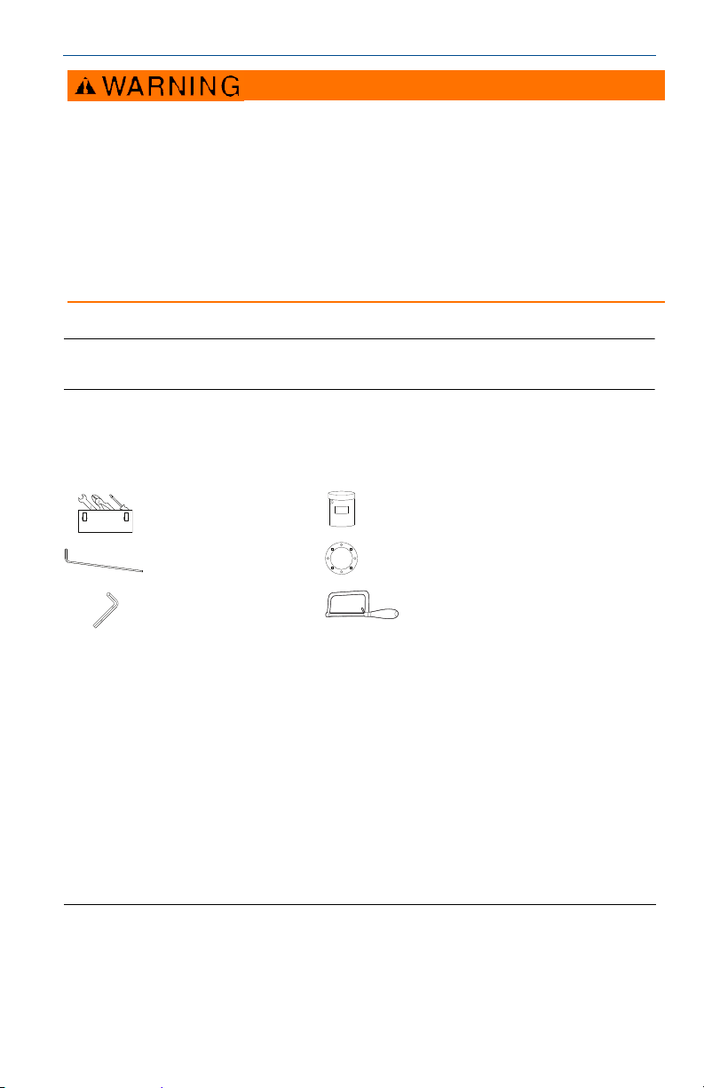
Standard tools, e.g.
screwdriver, wrench, pliers
Anti-seize paste or PTFE tape
(for NPT threaded connection)
Two support tools
(supplied)
Gasket
(for BSP/G threaded, flanged, and Tri Clamp
conne ctions)
Allen key
(supplied)
Saw
Failure to follow safe installation and service guidelines could result in serious injury.
Make sure only qualified personnel perform installation or service.
Use the equipment only as specified in t he relevant Quick Start Guide and Reference Manual:
Rosemount 3300 Series Reference Manual (document number 00809-0100-4811)
Rosemount 3308 Series Wireless Guided Wave Radar, 3308A Reference Manual (document number
00809-0100-4308)
Rosemount 5300 Series Reference Manual (document number 00809-0100-4530)
Rosemount 3300 Series Quick Start Guide (document number 00825-0100-4811)
Rosemount 3308 Series Wireless Guided Wave Radar, 3308A Quick Start Guides (document numbers
00825-0100-4308 and 00825-0300-4308)
Rosemount 5300 Series Quick Start Guide (document number 00825-0100-4530)
Failure to do so may impair the protection provided by the equipment.
August 2015
Note
The same instructions apply for the Rosemount 3300, 3308, and 5300 Series Transmitters.
Required equipment
Contents
Required equipment . . . . . . . . . . . . . . . . . . . . . . 2
Segmented probe parts . . . . . . . . . . . . . . . . . . . 3
Verify probe length . . . . . . . . . . . . . . . . . . . . . . . 4
2
Assemble the segmented probe . . . . . . . . . . . . 5
Adjust the probe length . . . . . . . . . . . . . . . . . . 17
Page 3
August 2015
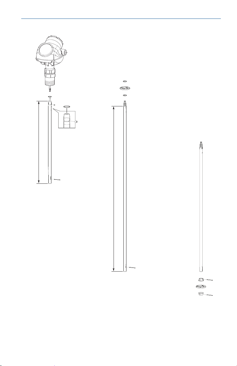
A
B
D
G
E
C
I
J
D
E
F
H
I
D
D
31.5
(800)
Dimensions are in inches (mm).
15.2
(385)
Segmented probe parts
Quick Start Guide
A. Safety ring F. Centering disc in PTFE (optional)
B. Screw G. Middle segment
C. To p se gme nt H. Bottom segment (length varies depending on total probe length)
D. Split pin I. Bushing (for the centering disc at the probe end)
E. PTFE washer (optional) J. Bottom centering disc in PTFE or Stainless Steel (optional)
3
Page 4

Quick Start Guide
L =
SN:
Probe length
Probe segments box
Verify probe length
Segmented probe ordered with model code 4S
Before installation, verify the probe length (L) on the label. If the probe length
needs to be adjusted, see “Adjust the probe length” on page 17.
Segmented probe ordered as spare part kit
Before installation, the number of segments that add up to the desired probe
length must be determined. Also, the bottom segment may need to be
shortened. See “Adjust the probe length” on page 17.
August 2015
4
Page 5

August 2015
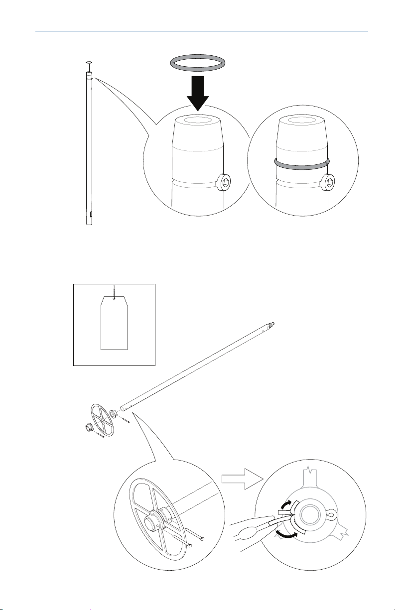
Top Segment
~
2 turns
Quick Start Guide
Assemble the segmented probe
Note
If there is enough space beside the tank, the probe can be assembled before inserting it into the
tank.
1. Insert the stop screw to the top segment. Tighten approximately 2 turns.
5
Page 6
Quick Start Guide
Bottom Segment
2. Pre-assemble the safety ring.
3. Optional: If ordered, mount the centering disc on the bottom segment of the
probe.
August 2015
6
Page 7

August 2015
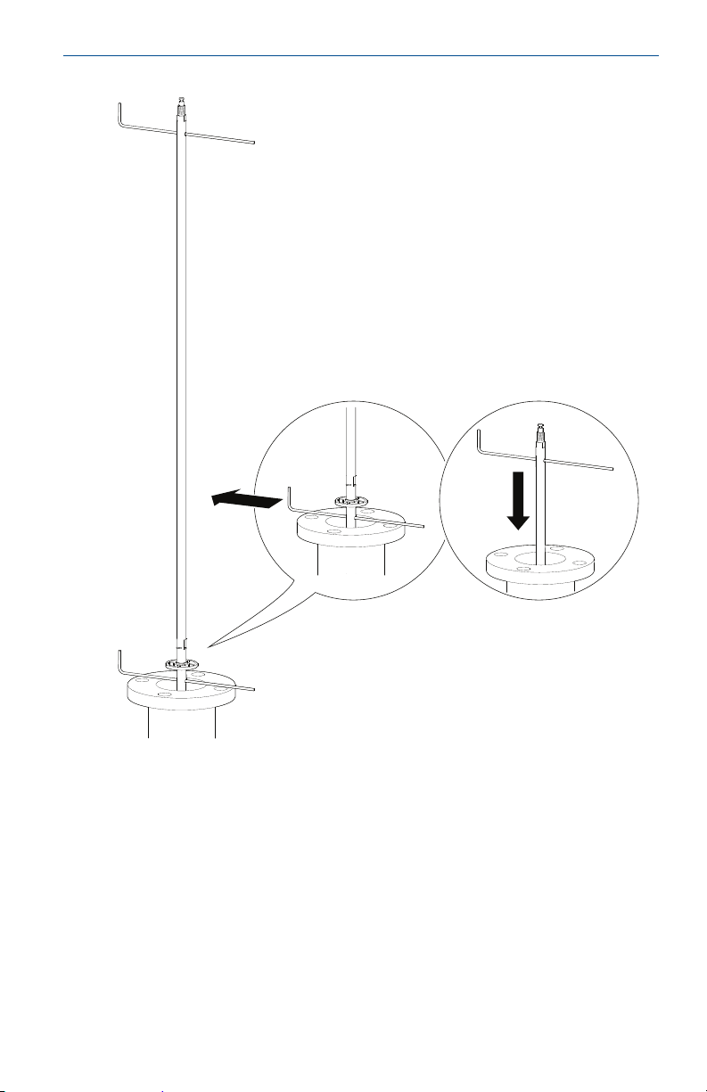
Bottom Segment
Note
Maximum five pcs/probe
Minimum two segments between each centering disc
4. Insert the support tool.
Quick Start Guide
5. Optional: If ordered, mount the centering disc.
7
Page 8

Quick Start Guide
Hand tighten
6. Mount a middle segment.
August 2015
8
Page 9

August 2015
7. Secure the split pin.
Quick Start Guide
9
Page 10

Quick Start Guide
8. Insert the second support tool.
August 2015
10
Page 11
August 2015
9. Remove the first support tool and lower the probe into the tank.
Quick Start Guide
10. Repeat steps 5 to 9 until all segments are mounted. Make sure to finish with
the top segment of the probe.
11
Page 12

Quick Start Guide
Use anti-seize paste or PTFE tape
according to your site procedures.
11. Seal and protect threads.
Only for NPT threaded tank connection.
August 2015
12
Page 13

August 2015
Flange / Tri Clamp Threaded
Gasket
Sealant on
threads (NPT)
or
Gasket (BSP/G)
Note
For safety reasons, at least two people are needed when mounting the device.
Make sure to hold the device above the tank. High loads can break the support tool.
12. Attach the probe to the device.
Quick Start Guide
13
Page 14

Quick Start Guide
13. Tighten the stop screw and slide the safety ring into the groove.
August 2015
14. Remove the support tool.
14
Page 15

August 2015
Flange ThreadedTri Clamp
15. Mount the device on the tank.
Quick Start Guide
16. Rotate the housing to the desired direction.
15
Page 16

Quick Start Guide
17. Tighten the nut. The torque must be 30 Lbft (40 Nm).
18. For the 3300 and 5300, connect the wiring.
For further instructions, see the Rosemount 3300 Series (document number
00825-0100-4811) and the Rosemount 5300 Series (document number
00825-0100-4530) Quick Start Guides.
August 2015
19. For the 3308A, insert power module and connect to device.
For further instructions, see the Rosemount 3308 Series Wireless Guided
Wave Radar, 3308A Quick Start Guides (document numbers
00825-0100-4308 and 00825-0300-4308).
16
Page 17

August 2015
L, desired probe length:
L
n, number of middle segments:
n
Y, length of bottom segment:
Y
Y < 0.4 in. (10 mm)
Y ≥ 0.4 in. (10 mm)
Y = 31.5 in. (800 mm)
Quick Start Guide
Adjust the probe length
1. Determine L, the desired probe length.
2. Determine n, the number of middle segments needed for the desired probe
length. See Tab l e 1 and Table 2 on page 19.
3. Calculate Y, the length of the bottom segment. See Tab l e 1 and Tab le 2 on
page 19.
4. Continue as follows:
Length of bottom segment (Y) Action
• Continue with step (7).
Do not use the bottom segment.
• Continue with step (5) and cut the
bottom segment.
1. Add one extra middle segment to
the calculated n.
2. Continue with step (7).
17
Page 18

Quick Start Guide
12
3
4
5
6
7
8
0
12
3
0
Y
Note
Make sure the bottom segment is fixed while cutting.
Y
Drilling fixture
5. Mark where to cut the bottom segment.
6. Cut the bottom segment at the mark.
August 2015
7. Optional: If a bottom centering disc is ordered, then drill two holes on the
bottom segment using the drilling fixture.
18
Page 19

August 2015
Quick Start Guide
Table 1. Determination of Probe Segments for Standard Seal
Desired probe length (L)
in. mm in. mm
15.8 ≤ L ≤ 47.2 400 ≤ L ≤ 1200 0 pc Y = L -15.8 Y = L - 400
47.2 < L ≤ 78.7 1200 < L ≤ 2000 1 pc Y = L - 47.2 Y = L - 1200
78.7 < L ≤ 110.2 2000 < L ≤ 2800 2 pcs Y = L - 78.7 Y = L - 2000
110.2 < L ≤ 141.7 2800 < L ≤ 3600 3 pcs Y = L - 110.2 Y = L - 2800
141.7 < L ≤ 173.2 3600 < L ≤ 4400 4 pcs Y = L - 141.7 Y = L - 3600
173.2 < L ≤ 204.7 4400 < L ≤ 5200 5 pcs Y = L - 173.2 Y = L - 4400
204.7 < L ≤ 236.2 5200 < L ≤ 6000 6 pcs Y = L - 204.7 Y = L - 5200
236.2 < L ≤ 267.7 6000 < L ≤ 6800 7 pcs Y = L - 236.2 Y = L - 6000
267.7 < L ≤ 299.2 6800 < L ≤ 7600 8 pcs Y = L - 267.7 Y = L - 6800
299.2 < L ≤ 330.7 7600 < L ≤ 8400 9 pcs Y = L - 299.2 Y = L - 7600
330.7 < L ≤ 362.2 8400 < L ≤ 9200 10 pcs Y = L - 330.7 Y = L - 8400
362.2 < L ≤ 393.7 9200 < L ≤ 10000 11 pcs Y = L - 362.2 Y = L - 9200
1. Maximum probe length is 19 ft 8 in. (6 m) for the 3300 Series and 32 ft 9 in. (10 m) for the 3308 and 5300
Series.
(1)
Number of middle
segments (n)
Length of bottom segment (Y)
Table 2. Determination of Probe Segments for HTHP/HP/C Seal
Desired probe length (L)
in. mm in. mm
17.3 ≤ L ≤ 48.8 440 ≤ L ≤ 1240 0 pc Y = L - 17.3 Y = L - 440
48.8 < L ≤ 80.3 1240 < L ≤ 2040 1 pc Y = L - 48.8 Y = L - 1240
80.3 < L ≤ 111.8 2040 < L ≤ 2840 2 pcs Y = L - 80.3 Y = L - 2040
111.8 < L ≤ 143.3 2840 < L ≤ 3640 3 pcs Y = L - 111.8 Y = L - 2840
143.3 < L ≤ 174.8 3640 < L ≤ 4440 4 pcs Y = L - 143.3 Y = L - 3640
174.8 < L ≤ 206.3 4440 < L ≤ 5240 5 pcs Y = L - 174.8 Y = L - 4440
206.3 < L ≤ 237.8 5240 < L ≤ 6040 6 pcs Y = L - 206.3 Y = L - 5240
237.8 < L ≤ 269.3 6040 < L ≤ 6840 7 pcs Y = L - 237.8 Y = L - 6040
269.3 < L ≤ 300.8 6840 < L ≤ 7640 8 pcs Y = L - 269.3 Y = L - 6840
300.8 < L ≤ 332.3 7640 < L ≤ 8440 9 pcs Y = L - 300.8 Y = L - 7640
332.3 < L ≤ 363.8 8440 < L ≤ 9240 10 pcs Y = L - 332.3 Y = L - 8440
363.8 < L ≤ 393.7 9240 < L ≤ 10000 11 pcs Y = L - 363.8 Y = L - 9240
1. Maximum probe length is 19 ft 8 in. (6 m) for the 3300 Series and 32 ft 9 in. (10 m) for the 3308 and 5300
Series.
(1)
Number of middle
segments (n)
Length of bottom segment (Y)
19
Page 20

Global Headquarters
Emerson Process Management
6021 Innovation Blvd.
Shakopee, MN 55379, USA
+1 800 999 9307 or +1 952 906 8888
+1 952 949 7001
RFQ.RMD-RCC@EmersonProcess.com
North America Regional Office
Emerson Process Management
8200 Market Blvd.
Chanhassen, MN 55317, USA
+1 800 999 9307 or +1 952 906 8888
+1 952 949 7001
RMT-NA.RCCRFQ@Emerson.com
Latin America Regional Office
Emerson Process Management
1300 Concord Terrace, Suite 400
Sunrise, Florida, 33323, USA
+1 954 846 5030
+1 954 846 5121
RFQ.RMD-RCC@EmersonProcess.com
Europe Regional Office
Emerson Process Management Europe GmbH
Neuhofstrasse 19a P.O. Box 1046
CH 6340 Baar
Switzerland
+41 (0) 41 768 6111
+41 (0) 41 768 6300
RFQ.RMD-RCC@EmersonProcess.com
Asia Pacific Regional Office
Emerson Process Management Asia Pacific Pte Ltd
1 Pandan Crescent
Singapore 128461
+65 6777 8211
+65 6777 0947
Enquiries@AP.EmersonProcess.com
Middle East and Africa Regional Office
Emerson Process Management
Emerson FZE P.O. Box 17033,
Jebel Ali Free Zone - South 2
Dubai, United Arab Emirates
+971 4 8118100
+971 4 8865465
RFQ.RMTMEA@Emerson.com
*00825-0300-4530*
Quick Start Guide
00825-0300-4530, Rev AC
Standard Terms and Conditions of Sale can be found at:
www.rosemount.com\terms_of_sale.
The Emerson logo is a trademark and service mark of Emerson Electric Co.
Rosemount and Rosemount logotype are registered trademarks of
Rosemount Inc.
All other marks are the property of their respective owners.
© 2015 Rosemount Inc. All rights reserved.
August 2015
 Loading...