

Page 1
Quick Start Guide
00825-0100-4327, Rev 01
Rosemount™ 326P Pressure Transmitter
January 2019
Page 2

2
Page 3

Quick Start Guide Contents
00825-0100-4327 January 2019
Contents
Chapter 1 Introduction.................................................................................................................. 5
1.1 Pressure specifications..................................................................................................................... 5
1.2 Operating modes............................................................................................................................. 7
1.3 Functions..........................................................................................................................................7
Chapter 2 Installation...................................................................................................................11
2.1 Installation orientation (3-A® standards).........................................................................................11
2.2 Hygienic process connection adapter installation...........................................................................11
2.3 Electrical connection...................................................................................................................... 11
Chapter 3 Operation.................................................................................................................... 15
3.1 Display and function buttons..........................................................................................................15
3.2 Menu..............................................................................................................................................17
3.3 Parameter settings......................................................................................................................... 21
Chapter 4 Setting ranges..............................................................................................................33
Chapter 5 Troubleshooting.......................................................................................................... 41
5.1 Error messages............................................................................................................................... 41
5.2 Warning messages......................................................................................................................... 41
Chapter 6 Product certifications...................................................................................................43
6.1 European directive information...................................................................................................... 43
6.2 Ordinary location information........................................................................................................ 43
6.3 3-A® certification............................................................................................................................43
6.4 Other industry certifications...........................................................................................................43
Chapter 7 Factory settings........................................................................................................... 45
Quick Start Guide 3
Page 4

Contents Quick Start Guide
January 2019 00825-0100-4327
4 Quick Start Guide
Page 5
Quick Start Guide Introduction
00825-0100-4327 January 2019
1 Introduction
The pressure transmitter measures and monitors pressure in a facility.
1.1 Pressure specifications
To ensure product performance and safety, adhere to the following specifications.
1.1.1 Measuring range
This table shows the range at which the pressure transmitter is able to measure pressure.
Pressure range Measuring range limits
inH2O mbar
1A -2.0 to 40 -5 to 99.5
2A -5.0 to 100 -12.4 to 248.8
1.1.2
psi bar
3A -14.5 to 14.5 -1 to 1
2B -0.73 to 14.5 -0.05 to 1
4A -1.45 to 20 -0.1 to 1.38
5A -1.8 to 36 -0.124 to 2.48
6A -14.5 to 55 -1 to 3.79
7A -14.5 to 85 -1 to 5.86
8A -14.5 to 145 -1 to 10
9A -14.5 to 230 -1 to 15.9
1B -14.5 to 360 -1 to 24.8
Note
The pressure transmitter is vacuum resistant. There are restrictions for nominal pressure
ranges at or below 4.35 psi (300 mbar). Adhere to the specifications in the data sheet.
Overpressure limits
The table in this topic shows maximum allowable pressure for the pressure transmitter.
CAUTION
Take appropriate measures to avoid exceeding the specified overpressure limits.
Quick Start Guide 5
Page 6
Introduction Quick Start Guide
January 2019 00825-0100-4327
Pressure range Overpressure limits
inH2O bar
1A 1606 4
2A 2400 6
psi bar
3A 145 10
2B 145 10
4A 215 15
5A 290 20
6A 435 30
7A 435 30
8A 725 50
9A 1085 75
1B 1450 100
1.1.3 Burst pressure limits
The burst pressure limit is the pressure at which the pressure transmitter will no longer
function or be damaged.
CAUTION
Do not exceed the burst pressure limit. Exceeding the burst pressure limit can damage the
pressure transmitter. Continuing to use the pressure transmitter after exceeding the burst
pressure limit can cause damage and physical injury.
Pressure range
1A 12044 30
2A 12044 30
3A 435 30
2B 435 30
4A 580 40
5A 725 50
6A 1450 100
Burst pressure limits
inH2O bar
psi bar
7A 1450 100
8A 2175 150
9A 3625 250
6 Quick Start Guide
Page 7

Quick Start Guide Introduction
00825-0100-4327 January 2019
Pressure range Burst pressure limits
1B 5075 350
1.2 Operating modes
The wiring configuration sets the operating mode. After wiring the pressure transmitter, it
automatically recognizes the connections and changes to the respective operating mode.
For more information, see Electrical connection.
1.2.1 Two-wire operation
OUT2 (pin 2)
The analog signal proportional to pressure (4-20 mA or 20-4 mA).
1.2.2 Three-wire operation
OUT1 (pin 4)
OUT2 (pin 2)
Switching signal for system pressure limit value
• Switching signal used for system pressure limit value
• Analog signal proportional to pressure (4-20 mA or 20-4 mA)
1.3 Functions
The Rosemount 326P Pressure transmitter performs the functions described in this
section.
1.3.1
Switching function
The switching function is available only for three-wire operations. OUT1 or OUT2 changes
its switching status if the pressure is above or below the set switching limits (SPx, rPx).
These switching functions are available:
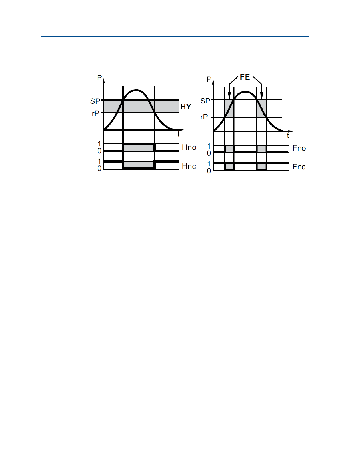
• Hysteresis function/normally open: OUx = Hno (Figure 1-1)
• Hysteresis function/normally closed: OUx = Hnc (Figure 1-1)
First set the set point (SPx), then the reset point (rPx) with the requested difference.
• Window function/normally open: OUx = Fno (Figure 1-2)
• Window function/normally closed: OUx = Fnc (Figure 1-2)
Set the width of the window using the difference between SPx and rPx. SPx is the upper
value and rPx is the lower value.
Quick Start Guide 7
Page 8
Introduction Quick Start Guide
January 2019 00825-0100-4327
Figure 1-1: Hysteresis function Figure 1-2: Window function
• SP: Set point
• rP: Reset point
• P: Pressure
• Hy: Hysteresis
• Hno: Hysteresis function/normally open
• Hnc: Hysteresis function/normally closed
1.3.2 Analog signal
The transmitter communicates measured pressure using an analog signal.
OU2 defines whether the set measuring range is provided as 4-20 mA (OU2 = I) or as 20-4
mA (OU2 = InEG).
Rerange the transmitter (set new values for ASP and AEP) by either manually entering
range points or with an applied pressure source.
• Applying a pressure source for the analog start point (tASP) or manually setting the
parameter (ASP) defines the measured value when the analog signal is 4 mA (20 mA at
InEG).
• Applying a pressure source for the analog end point (tASP) or manually setting the
parameter (ASP) defines the measured value when the output signal is 20 mA (4 mA at
InEG).
• FE: Window
• Fno: Window function/normally open
• Fnc: Window function/normally closed
Minimum distance between ASP and AEP is 25 percent of the upper range limit (maximum
rangedown 4:1). For pressure range 3A, the minimum distance is 25 percent of the
measuring span.
8 Quick Start Guide
Page 9
Quick Start Guide
00825-0100-4327 January 2019
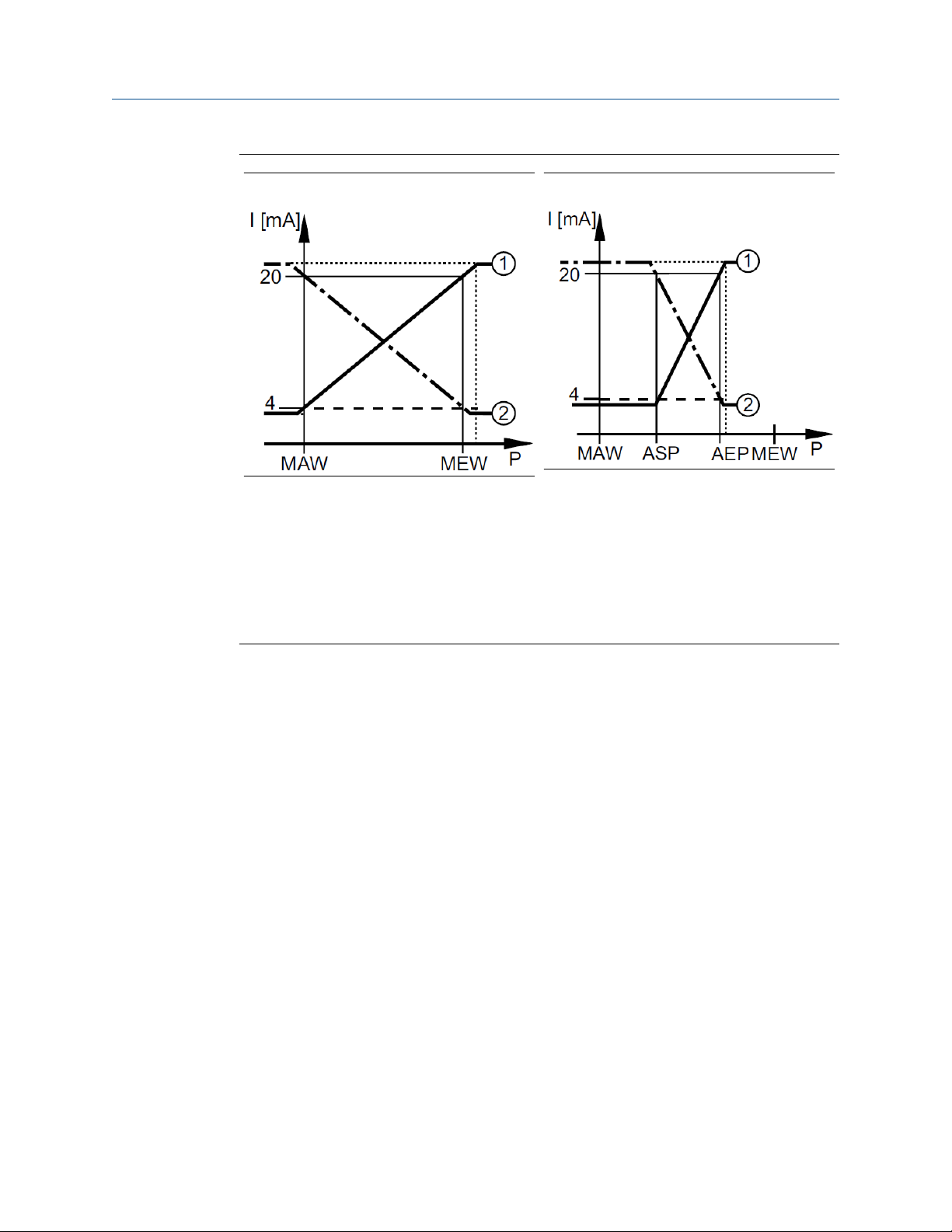
Figure 1-3: Factory setting Figure 1-4: Transmitter reranged
P: system pressure
Introduction
1.3.3
MAW: initial value of the measuring range (Lower range limit [LRL])
MEW: final value of the measuring range (Upper range limit [URL])
1: OU2 = I
2: OU2 = InEG
In the set measuring range the output signal is between 4 and 20 mA (OU2 = I) or between
20 and 4 mA (OU2 = InEG). When pressure is outside the set measuring range, the output
signal is as follows:
• System pressure above the measuring range:
— Output signal > 20 mA if OU2 = I.
— Output signal 4 to 3.8 mA if OU2 = InEG.
• System pressure below the measuring range:
— Output signal 4 to 3.8 mA if OU2 = I.
— Output signal > 20 mA if OU2 = InEG.
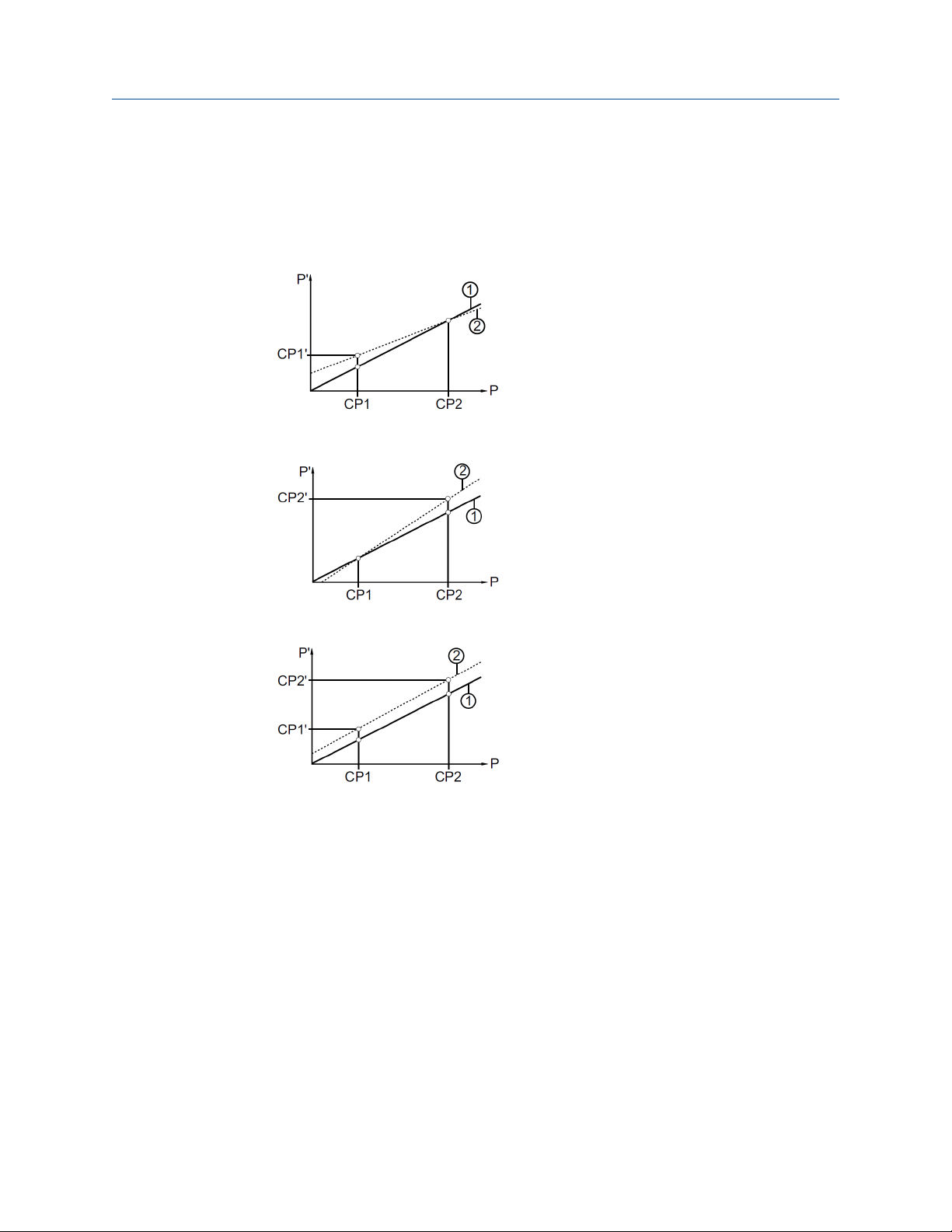
Customer-specific calibration (sensor trim)
A customer specific calibration (sensor trim) corrects the pressure offset and pressure
range to match a pressure standard. This provides a slope correction to the transmitter's
current characterization curve. An accurate pressure standard is required for a full
calibration. For more information on performing a Sensor Trim, see Perform a sensor trim.
• Sensor Trim is a two-point sensor calibration that applies two end-point pressures
(CP1, CP2) then linearizes the output between them. CP1 and CP2 must be within the
scaled measuring range. For more information, see Analog signal.
• Zero trim is a single-point offset adjustment. It compensates for mounting position
effects and is most effective when performed with the transmitter installed in its final
Quick Start Guide 9
Page 10
Introduction Quick Start Guide
January 2019 00825-0100-4327
mounting position. Since zero trim maintains the slope of the characterization curve,
do not use it in place of a Sensor Trim over the full sensor range. For more information,
see Perform manual zero trim.
Reset the calibration by resetting all parameters to the factory default settings. For more
information, see Resetting all parameters to factory default settings.
• P: measured pressure
P‘: modified measured value
• CP1: calibration point 1
CP1‘: modified measured value for CP1
• CP2: calibration point 2
• 1: curve of measured values at factory
setting
• 2: curve of measured values after calibration
• P: measured pressure
P‘: modified measured value
• CP1: calibration point 1
CP2: calibration point 2
CP2‘: modified measured value for CP2
• 1: curve of measured values at factory
setting
• 2: curve of measured values after calibration
• P: measured pressure
P‘: modified measured value
• CP1: calibration point 1
CP1‘: modified measured value for CP1
• CP2: calibration point 2
CP2‘: modified measured value for CP2
• 1: curve of measured values at factory
setting
• 2: curve of measured values after calibration
10 Quick Start Guide
Page 11

Quick Start Guide
00825-0100-4327 January 2019
Installation
2 Installation
This section contains instructions for installing and wiring the Rosemount 326P Pressure
Transmitter.
Note
Before installing or removing the unit, ensure no pressure is applied to the system. Note
that when the pressure transmitter displays 0%, pressure might still be applied to the
system.
2.1 Installation orientation (3-A® standards)
For optimized cleaning of the measuring element in hygienic areas according to the 3-A
standards, follow these guidelines when installing the pressure transmitter.
To ensure the medium can run off the measuring element, do not install the unit at the
lowest point of a pipe or container.
Note
This product is not suitable for use where the criteria for paragraph E1.2 / 63-03 of the
3-A® standard 63-03 must be met.
2.2 Hygienic process connection adapter installation
Hygienic process connection adapters allow the transmitter to be installed according to
application requirements. All connection adapters include an EPDM O-ring. More sealing
rings are available to be ordered as accessories. See the Rosemount 326P Product Data
Sheet for all available connectors and accessories. Hygienic process connection adapters
include installation instructions with the packaging.
2.3 Electrical connection
This section provides instructions for wiring the pressure transmitter. A qualified
electrician must wire the pressure transmitter. The electrical installation must adhere to
national and international regulations.
Voltage supply according to EN 50178, SELV, PELV.
2.3.1
Wiring for two-wire operation
Follow these steps to wire the pressure transmitter for two-wire operation.
Procedure
1. Disconnect the power.
2. Wire the pressure transmitter according to Figure 2-1.
Quick Start Guide 11
Page 12
Installation Quick Start Guide
January 2019 00825-0100-4327
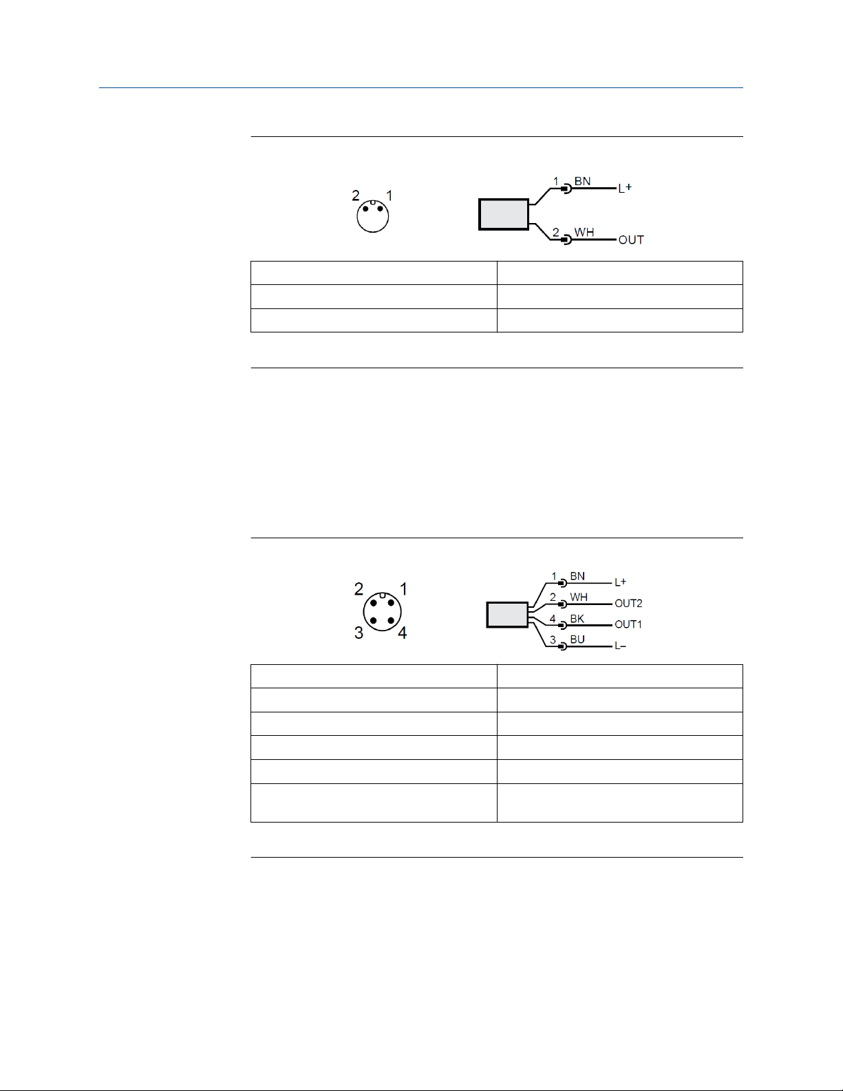
Figure 2-1: Connection for two-wire operation
BN Brown
WH White
OUT Analog output (4-20 mA)
Colors to DIN EN 60947-5-2
2.3.2
Wiring for three-wire operation
Follow these steps to wire the pressure transmitter for three-wire operation.
Procedure
1. Disconnect the power.
2. Wire the pressure transmitter according to Figure 2-2.
Figure 2-2: Connection for three-wire operation
BK
BN Brown
BU Blue
WH White
OUT1 Switching output
OUT2 Switching output or analog output (4-20
Black
mA)
Colors to DIN EN 60947-5-2
12 Quick Start Guide
Page 13
Quick Start Guide Installation
00825-0100-4327 January 2019
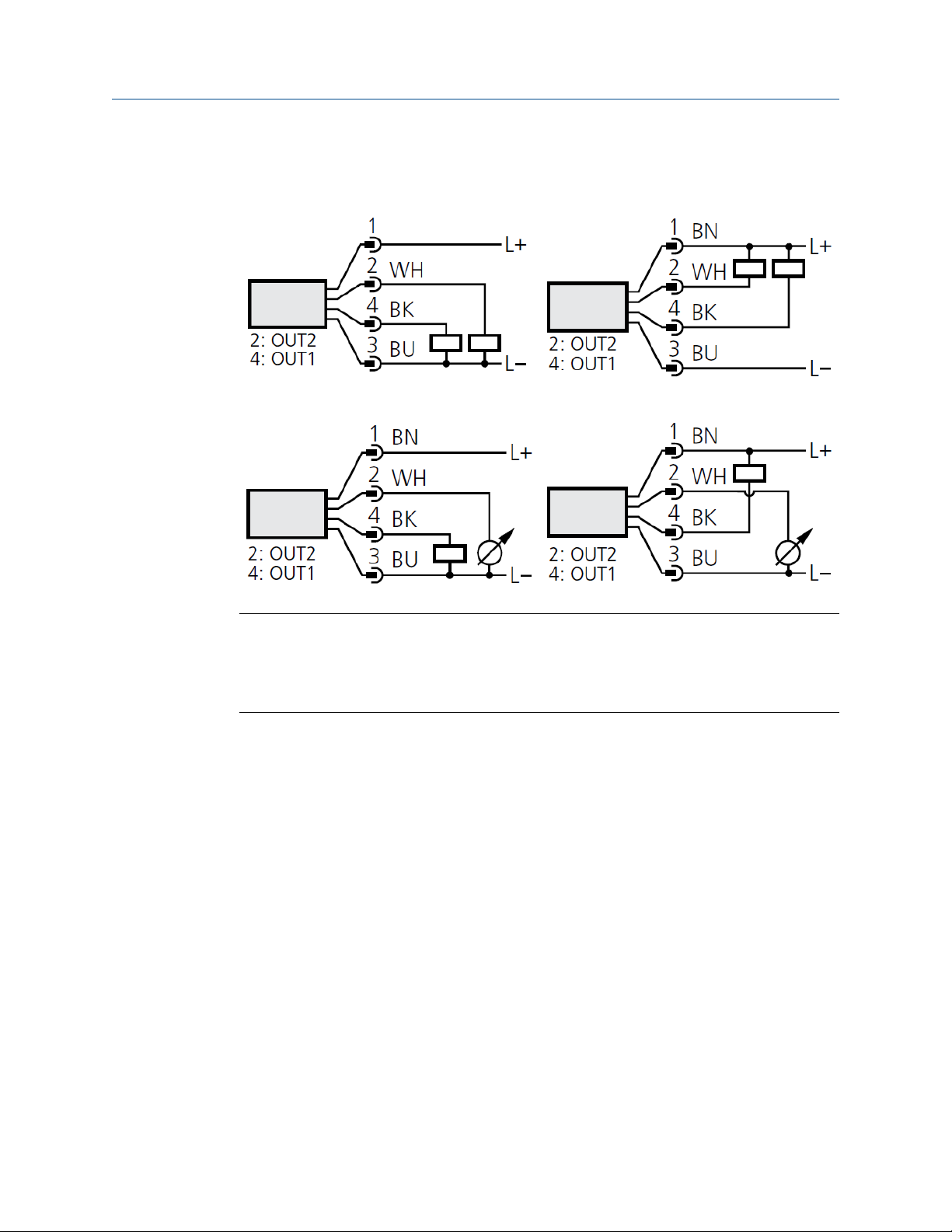
Wiring examples
2 x positive switching 2 x negative switching
1 x positive switching / 1 x analog 1 x negative switching / 1 x analog
Note
If the analog signal current (I) is selected in the menu under OU2 and the output is not
connected (resistor = infinite), the pressure transmitter displays the error message W532
in intervals. This does not affect the measuring result. As an alternative, configure OU2 to
a switching output.
Quick Start Guide 13
Page 14

Installation Quick Start Guide
January 2019 00825-0100-4327
14 Quick Start Guide
Page 15
Quick Start Guide Operation
00825-0100-4327 January 2019
3 Operation
This section provides instructions for configuring parameter settings.
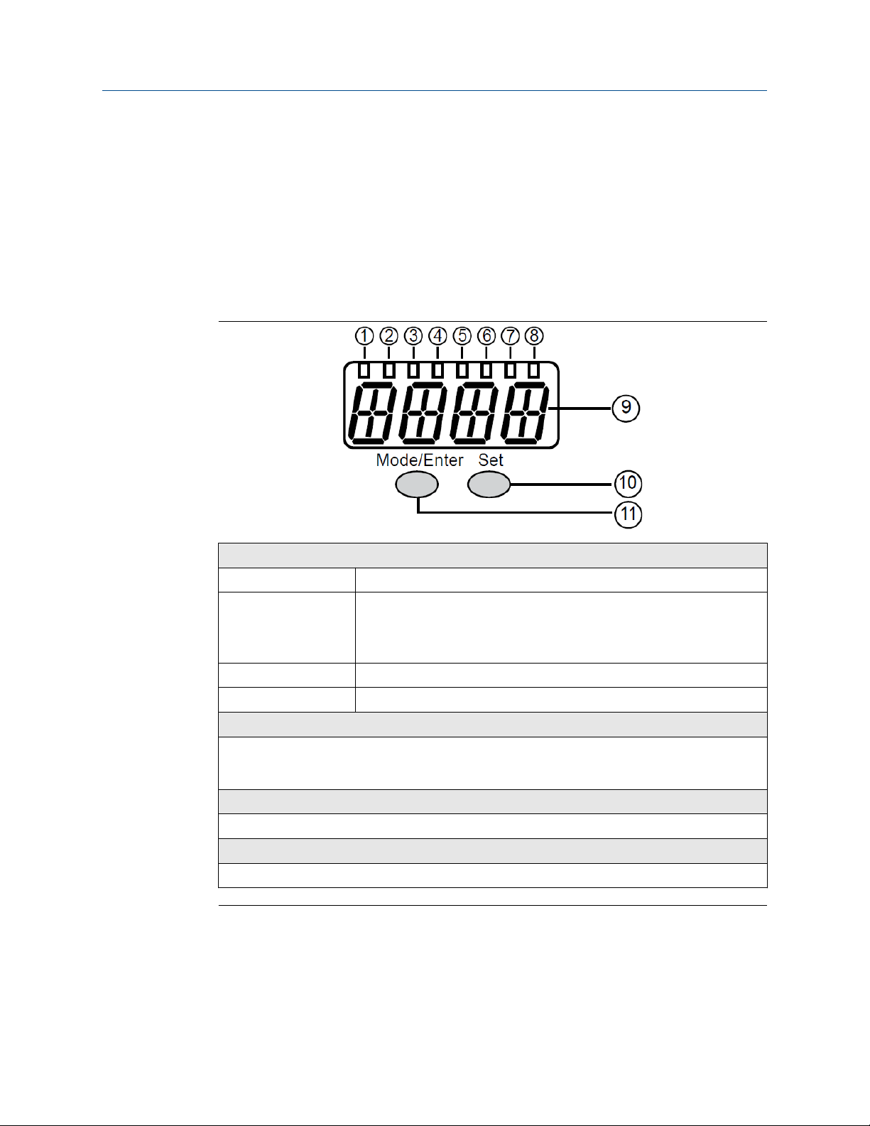
3.1 Display and function buttons
The pressure transmitter displays information using the display and can be controlled
using the function buttons.
1 to 8: Indicator LEDs
LED 1 to LED 5 System pressure in the set unit of measurement.
LED 6 If OU2 is configured as an analog output, it indicates the system pressure
in percent of the scaling of the analog output (range ASP to AEP).
If OU2 is configured as a switching output, it indicates the system
pressure in percent of the upper range limit (URL).
LED 7 Switching status of OUT2 (illuminates when output 2 is switched).
LED 8 Switching status of OUT1 (illuminates if output 1 is switched).
9: Alphanumeric display, 4 digits
• Current system pressure
• Parameters and parameter values
10: Set button
Selects a parameter from the menu and modifies the value by holding pressed for five seconds.
11: Mode/Enter button
Scrolls through the menu and acknowledges parameter values.
Quick Start Guide 15
Page 16

Operation Quick Start Guide
January 2019 00825-0100-4327
3.1.1 Read the set parameters
Follow these steps to view the set parameter values.
Procedure
1. Press Mode/Enter until the pressure transmitter displays the desired parameter.
2. Press Set.
The pressure transmitter displays the value currently set for the selected parameter
for 15 seconds then returns to run mode.
3.1.2 Change the display in run mode
Follow these steps to view the pressure measurement in different indicator types. During
normal operation, the pressure transmitter displays the pressure measurement in the
selected unit of measurement.
Procedure
• Press Set.
The pressure transmitter displays the following information for 15 seconds:
— System pressure in percent of the set scaling of the analog output if OU2 is
configured as analog output.
— System pressure in percent of the upper range limit if OU2 is configured as
switching output.
16 Quick Start Guide
Page 17

Quick Start Guide Operation
00825-0100-4327 January 2019
3.2 Menu
This section explains the pressure transmitter menu options and structure.
3.2.1 Main menu structure
The main menu includes options for accessing other menus, setting output functions, and
changing the display mode.
Figure 3-1: Main menu
• 1: Change to the extended functions menu (level 2)
• Menu items highlighted gray are not available for two-wire operation.
Option
SP1/rP1
OU1
OU2 Output function for OUT2:
tCOF Perform Zero Trim.
Quick Start Guide 17
(1)
(1)
Description
Upper and lower limit values for system pressure at which OUT1 switches.
Output function for OUT1:
Switching signal for the pressure limit values: hysteresis function (H ..) or
window function (F ..), either normally open (. no) or normally closed (. nc).
• Switching signal for the pressure limit values: hysteresis function (H ..) or
window function (F ..), either normally open (. no) or normally closed (. nc);
(only available for three-wire operation).
• analog signal for the current system pressure: 4-20 mA (I), 20-4 mA (InEG).
Page 18

Operation
January 2019 00825-0100-4327
Option Description
tASP Set analog start point (4 mA if OU2 = I, 20 mA if OU2 = InEG) using an applied
pressure source.
tAEP Set analog end point (20 mA if OU2 = I, 4 mA if OU2 = InEG) using an applied
pressure source.
SP2/rP2
EF Extended functions and opening the extended functions menu (level 2).
(1) Not active in a two-wire operation.
(1)
Upper and lower limit values for system pressure at which OUT2 switches.
Quick Start Guide
3.2.2 Extended functions menu
The extended functions menu provides options for configuring pressure transmitter
parameters.
Figure 3-2: Extended functions menu (level 2)
• 1: Change to the main menu
• 2: Change to the simulation menu
Menu items highlighted gray are not available for two-wire operation.
18 Quick Start Guide
Page 19

Quick Start Guide Operation
00825-0100-4327 January 2019
Table 3-1: Extended functions menu options
Option Description
Uni Standard unit of measurement for system pressure
SELd Display mode:
1. Pressure in the unit set in Uni
2. Pressure in percent of the set scaling of the analog output
ASP Analog start point for system pressure: measured value at which 4 mA is
provided (20 mA if OU2 = InEG)
AEP Analog end point for system pressure: measured value at which 20 mA is
provided (4 mA if OU2 = InEG)
HI Highest measured system pressure
LO Lowest measured system pressure
COF Zero trim
(1)
dS1
(1)
dr1
dS2
(1)
dr2
FOU1
(1)
(1)
Switch-on delay for OUT1
Switch-off delay for OUT1
Switch-on delay for OUT2; only active if OU2 = Hnc, Hno, Fnc or Fno
Switch-off delay for OUT2; only active if OU2 = Hnc, Hno, Fnc or Fno
Status of output 1 in case of an internal fault
FOU2 Status of output 2 in case of an internal fault
(1)
P-n
Switching logic for the outputs: pnp or npn
dAP Damping for switching outputs and display
dAA Damping for analog output (OUT2)
diS Update rate and orientation of the display
CAL Calibration function (setting the curve of measured values)
CP1 Calibration point 1
CP2 Calibration point 2
SIM Switch to the simulation menu (level 3)
rES Restore factory default settings
(1) Not active in a two-wire operation.
Quick Start Guide 19
Page 20

Operation Quick Start Guide
January 2019 00825-0100-4327
3.2.3 Simulation menu
The simulation menu provides options for configuring and executing transmitter
simulations.
Figure 3-3: Simulation menu (SEL=OU)
The options shown appear when SEL is set to OU.
Table 3-2: Simulation menu (SEL=OU)
Option Description
SEL Status to be simulated. Output functions OU.
(1)
S.OU1
S.OU2 Simulation values for OUT2; only active if SEL = OU.
S.TIM Time for the simulation process in minutes.
S.ON Starts the simulation process.
(1) Not active in two-wire operation
Simulation values for OUT1; only active for three-wire operation and if SEL =
OU.
• OPEN: Output inactive
• CLOS: Output active
• For three-wire operation and if OUT2 has been configured as switching
output: output inactive (OPEN) or active (CLOS).
• If OUT2 is set as an analog output: analog signal between 3.6 and 21.1 mA
During the simulation process the display alternately shows SIM and the
current operation indication.
If the simulation process is aborted, the pressure transmitter displays S.OFF for
two seconds, then SEL is active again.
20 Quick Start Guide
Page 21

Quick Start Guide Operation
00825-0100-4327 January 2019
Figure 3-4: Simulation menu (SEL = Proc)
The options shown appear when SEL is set to OU.
Table 3-3: Simulation menu (SEL = Proc)
Option Description
SEL Status to be simulated: Process value Proc.
S.Pr Simulation of a process value; active only if SEL = Proc. Any value between
lower and upper range limits (LRL and URL).
S.TIM Time for the simulation process in minutes.
S.ON Starts the simulation process.
During the simulation process the display alternately shows SIM and the
current operation indication.
If the simulation process is aborted, the pressure transmitter displays S.OFF for
two seconds, then SEL is active again.
3.3 Parameter settings
This section provides instructions for modifying parameter values. While modifying
parameter values, the pressure transmitter remains in operating mode. It continues to
monitor pressure levels using the existing parameter values until the new parameter
Quick Start Guide 21
Page 22

Operation
January 2019 00825-0100-4327
values are set. The pressure transmitter changes the parameter values immediately for
COF, CP1, and CP2.
Quick Start Guide
3.3.1 Modify parameter settings
Follow these steps to modify parameter values.
Procedure
1. Press Mode/Enter to select a parameter.
2. Press and hold Set.
The pressure transmitter flashes the current value for five seconds.
3. Modify the parameter value.
• Press Set to change the value incrementally.
• Press and hold Set to change the value continuously.
• To reduce the value, continue to press Set until the pressure transmitter reaches
the value limit and restarts at the value minimum.
4. Press Mode/Enter.
The pressure transmitter displays the parameter and saves the new parameter
value.
Switching menu levels
Follow these steps to change from the main menu to the extended functions menu.
Procedure
1. Press Mode/Enter until the pressure transmitter displays EF.
2. Press Set.
The pressure transmitter displays Uni.
3. If the extended menu is locked with an access code, enter the access code.
a) Press Set until the pressure transmitter displays the valid access code.
b) Press Mode/Enter.
By default the extended functions menu is unlocked.
Locking and unlocking the pressure transmitter
Follow these steps to lock or unlock the pressure transmitter. While locked, the pressure
transmitter does not allow parameter values to change and displays Loc if attempted.
Procedure
1. To lock: press and hold Mode/Enter and Set for 10 seconds.
The pressure transmitter locks and displays Loc.
2. To unlock: press and hold Mode/Enter and Set for 10 seconds while the pressure
transmitter is locked.
The pressure transmitter unlocks and displays uLoc.
22 Quick Start Guide
Page 23

Quick Start Guide
00825-0100-4327 January 2019
Operation
3.3.2 Configuring the display
This section provides instructions for changing how the pressure transmitter displays
pressure data.
Change the unit of measurement
Follow these steps to change the unit of measurement in which the pressure transmitter
displays process pressure.
Procedure
1. Select Uni from the extended functions menu.
2. Press and hold Set to modify the parameter value.
3. Select a unit of measurement.
• For bar or mbar, select bAr or mbAr
• For mPa or kPa, select MPA or kPA
• For psi, select PSI (only available with pressure ranges 3A, 5A, 6A, 8A, 1B, 2B)
• For InH2O, select IH2O (only available with pressure ranges 1A, 2A, 3A, 5A, 2B)
• For mWS, select mWS (only available with pressure ranges 3A, 5A, 2B)
• For mmWS, select mmWS (only available with pressure ranges 1A, 2A)
4. Press Mode/Enter.
Change the indication type
Follow these steps to change how the pressure transmitter displays pressure level.
Procedure
1. Select SELd from the extended functions menu.
2. Press and hold Set to modify the parameter value.
3. Select a type of indication.
• P: system pressure in the unit set in Uni.
• P%: system pressure in percent of the set scaling of the analog output; the
following applies: 0% = ASP value ; 100% = AEP value. If OU2 is configured as
switching output, ASP and AEP are not active. In this case the following applies:
0% = lower range limit (LRL) / 100% = upper range limit (URL).
4. Press Mode/Enter.
Note
Pressure may still be applied to the system if the pressure transmitter shows 0%
pressure.
Quick Start Guide 23
Page 24

Operation
January 2019 00825-0100-4327
Quick Start Guide
Change the update rate and display orientation
The update rate sets how often the pressure transmitter displays new data. The diS
parameter also sets the orientation of the display. Follow these steps to change the update
rate and orientation of the display.
Procedure
1. Select diS from the extended functions menu.
2. Press and hold Set to modify the parameter value.
3. Select an update rate or an update rate with a rotated display.
• d1: Updates the measured values every 50 ms.
• d2: Updates the measured values every 200 ms.
• d3: Updates the measured values every 600 ms.
• rd1, rd2, rd3: Rotates the display by 180° and selects the corresponding update
rate.
• OFF: Deactivates the display while in run mode. When a button is pressed, the
pressure transmitter displays the system pressure for 15 seconds. Pressing
Mode/Enter again activates the display. The LED indicators remain active when
the display is deactivated. Also, the pressure transmitter displays error messages
when the display is deactivated.
3.3.3
Set output signals
This section provides instructions for setting output functions and limits.
Setting output functions
Follow these steps to set the function of output 1 and output 2.
Procedure
1. Select OU1 from the menu.
2. Press and hold Set to modify the parameter value.
3. Set the switching function.
• Hno: hysteresis function/NO
• Hnc: hysteresis function/NC
• Fno: window function/NO
• Fnc: window function/NC
4. Press Mode/Enter.
5. Select OU2 from the menu.
6. Press and hold Set to modify the parameter value.
7. Set the function.
• Hno: hysteresis function/NO
24 Quick Start Guide
Page 25

Quick Start Guide
00825-0100-4327 January 2019
• Hnc: hysteresis function/NC
• Fno: window function/NO
• Fnc: window function/NC
• I: current signal proportional to pressure 4-20 mA
• InEG: current signal proportional to pressure 20-4 mA
8. Press Mode/Enter.
Operation
Set switching limits
Follow these steps to set the limits that cause the outputs to switch.
Procedure
1. Select SP1 or SP2 from the menu.
2. Press and hold Set to modify the parameter value.
3. Set the limit at which the output switches.
4. Press Mode/Enter.
5. Select rP1 or rP2 from the menu.
6. Press and hold Set to modify the parameter value.
7. Set the limit at which the output resets.
The rPx value is always lower than SPx. The pressure transmitter accepts only values
lower than the value for SPx.
8. Press Mode/Enter.
Automatically scale the analog output
Follow these steps to set the start and end value of the analog output to the current
system pressure reading. If the automatic setting is invalid, the pressure transmitter
displays UL or OL. After acknowledging an incorrect value, the pressure senor displays Err
and does not accept the incorrect value.
Procedure
1. Set the minimum pressure requested in the system.
a) Select tASP from the menu.
b) Press and hold Set.
The display flashes the current set value.
c) Release Set when the value stops flashing.
The pressure transmitter displays the new value.
d) Press Mode/Enter.
The current system pressure is defined as the start value for the analog
signal.
2. Set the maximum pressure requested in the system.
a) Select tAEP from the menu.
Quick Start Guide 25
Page 26

Operation
January 2019 00825-0100-4327
b) Press and hold Set.
The current value flashes on the display.
c) Release Set when the value stops flashing.
The pressure transmitter displays the new value.
d) Press Mode/Enter.
The pressure transmitter sets the current system pressure as the end value
for the analog signal.
Quick Start Guide
Manually scale the analog output
Follow these steps to manually set the start value (ASP) and end value (AEP) for the analog
output. The values for ASP and AEP must be within defined limits.
Procedure
1. Select ASP from the extended functions menu.
2. Press and hold Set to modify the parameter value.
3. Set the measured value at which the pressure transmitter provides 4 mA (20 mA if
OU2 = InEG).
4. Select AEP from the extended functions menu.
5. Press and hold Set to modify the parameter value.
6. Set the measured value at which the pressure transmitter provides 20 mA (4 mA if
OU2 = InEG).
3.3.4
Note
The minimum distance between ASP and AEP must be 25 percent of the upper
range limit (maximum rangedown is 4:1).
Optional settings
This section provides instructions for modifying optional settings. Modification of these
settings is not required for normal operation of the pressure transmitter.
Perform manual zero trim
Follow these steps to manually scale the pressure offset by +/-5 percent. Use this after
installation to trim out any measurement offsets because of mounting effects.
Procedure
1. Select COF from the extended functions menu.
2. Press and hold Set to modify the parameter value.
3. Set the value between -5% and 5%.
The pressure transmitter modifies the measured pressure by this value.
26 Quick Start Guide
Page 27

Quick Start Guide Operation
00825-0100-4327 January 2019
Perform an automatic zero trim
Follow these steps to automatically scale the pressure offset by +/-5 percent. Use this after
installation to trim out any measurement offsets because of mounting effects.
Prerequisites
Ensure no pressure is applied to the pressure transmitter.
Procedure
1. Select tCOF from the menu.
2. Press and hold Set.
The current offset value appears then the current system pressure appears.
3. Release Set.
4. Press Mode/Enter to confirm the new offset value.
Setting output reaction to fault conditions
Follow these steps to modify how the outputs react to fault conditions.
Procedure
1. Select FOU1 from the extended functions menu.
2. Press and hold Set to modify the parameter value.
3. Set the value for output 1.
• On: output 1 switches on in case of a fault.
• OFF: output 1 switches off in case of a fault.
• OU: output 1 switches irrespective of a fault as defined by parameters SP1, rP1
und OU1.
4. Select FOU2 from the extended functions menu.
5. Press and hold Set to modify the parameter value.
6. Set the value for output 2.
• On: output 2 switches on in case of a fault, the analog signal goes to the upper
final value.
• OFF: output 2 switches off in case of a fault, the analog signal goes to the lower
final value.
• OU: output 2 switches irrespective of the fault as defined by parameters SP2,
rP2, OU2. The analog signal corresponds to the measured value.
Postrequisites
For more information on error messages, see Error messages.
Quick Start Guide 27
Page 28

Operation
January 2019 00825-0100-4327
Quick Start Guide
Setting a delay for the switching outputs
Follow these steps to modify the time before an output switches after a fault. The
maximum delay time is 50 seconds.
Procedure
1. Select the switch-on delay parameter for the output from the extended functions
menu.
• Select dS1 to modify the switch-on delay for OUT1.
• Select dS2 to modify the switch-on delay for OUT2.
2. Press and hold Set to modify the parameter value.
3. Set the value between 0.1 and 50 seconds.
4. Select the switch-off delay parameter for the output from the extended functions
menu.
• Select dr1 to modify the switch-off delay for OUT1.
• Select dr2 to modify the switch-off delay for OUT2.
5. Press and hold Set to modify the parameter value.
6. Set the value between 0.1 and 50 seconds.
Setting the value to 0.0 deactivates the delay.
Setting the output logic for the switching outputs
Follow these steps to change the output logic for the switching outputs.
Procedure
1. Select P-n from the extended functions menu.
2. Press and hold Set to modify the parameter value.
3. Set the parameter to PnP or nPn.
4. Press Mode/Enter.
Setting damping for the switching signal
Damping the switching signal prevents the outputs from erroneously switching because of
erratic pressure readings. The damping value is the response time in seconds between
pressure change and change to the switching status. The damping value also influences
the value displayed on the pressure transmitter and the switching frequency (fmax = 1 ÷
2dAP).
Procedure
1. Select dAP from the extended functions menu.
2. Press and hold Set to modify the parameter value.
3. Set the value between 0.0 and 30 seconds.
A value of 0.0 seconds deactivates damping.
4. Press Mode/Enter.
28 Quick Start Guide
Page 29

Quick Start Guide
00825-0100-4327 January 2019
Operation
Setting a damping for the analog signal
Damping the analog signal prevents the 4-20 mA output from erroneously changing
because of erratic pressure readings. The analog damping value is the response time in
seconds between pressure change and the change of the analog signal.
Procedure
1. Select dAA from the extended functions menu.
2. Press and hold Set to modify the parameter value.
3. Set a value between 0.01 and 99.99 seconds.
A value of 0.0 seconds deactivates damping.
4. Press Mode/Enter.
Perform a sensor trim
Follow these steps to perform a sensor trim and calibrate the pressure transmitter
measurement.
Procedure
1. Apply a defined reference pressure to the transmitter between ASP and AEP.
2. Select CAL from the menu.
3. Press Set.
The pressure transmitter displays CP1.
4. Press and hold Set for five seconds.
The pressure transmitter displays the current pressure measurement.
5. Press Set until the pressure transmitter displays the reference pressure.
The pressure output can change by up to two percent of the upper range limit.
6. Press Mode/Enter.
The pressure transmitter displays CP1.
7. Press Mode/Enter again.
The pressure transmitter displays CP2.
8. To apply a second point on the curve or measured values, apply a second defined
reference pressure to the transmitter.
The minimum distance between the calibration points CP1 and CP2 is five percent
of the upper range limit.
9. Press and hold Set for five seconds.
The pressure transmitter displays the current pressure measurement.
10. Press Set until the pressure transmitter displays the reference pressure or the
corresponding analog signal is provided on OUT2.
The pressure output can change by up to two percent of the upper range limit.
11. Press Mode/Enter.
The pressure transmitter displays CP2.
12. Press Mode/Enter again.
The pressure transmitter displays CAL.
Quick Start Guide 29
Page 30

Operation
January 2019 00825-0100-4327
Quick Start Guide
3.3.5 Service fuctions
This section provides instructions for viewing and managing parameters.
View the highest and lowest measured pressure
The pressure transmitter saves the highest and lowest measured preasure values. Follow
these steps to view the highest and lowest pressure values previously measured by the
pressure transmitter.
Procedure
1. To view the maximum pressure value, select HI from the extended functions menu.
2. To view the minimum pressure value, select LO from the extended functions menu.
Deleting high and low pressure memory
Follow these steps to clear the highest and lowest pressure readings on the pressure
transmitter.
Procedure
3.3.6
1. Select HI or LO from the extended functions menu.
2. Press and hold Set until the pressure transmitter displays ---.
3. Press Mode/Enter.
Resetting all parameters to factory default settings
Follow these steps to reset all of the parameters to the factory default settings.
Prerequisites
Before resetting the parameters, record the current parameters using Factory settings.
Procedure
1. Select rES from the extended functions menu.
2. Press and hold Set until the pressure transmitter displays ---.
3. Press Mode/Enter.
Simulation function
During a simulation, the pressure transmitter replicates error conditions for testing
purposes. This section includes instructions for using the simulation function.
Open the simulation menu
Open the simulation menu to view simulation options and parameters.
Procedure
1. Select EF from the menu.
2. Press Set.
30 Quick Start Guide
Page 31

Quick Start Guide
00825-0100-4327 January 2019
The extended functions menu opens.
3. Select SIM from the menu.
4. Press Set.
The simulation menu opens. The first option is SEL.
Operation
Set the simulation output state
Follow these steps to set the output state for a simulation.
Procedure
1. Select SEL from the simulation menu.
2. Press and hold Set to change the simulation menu to OU.
3. For three-wire operation, select S.OU1 from the simulation menu.
For two-wire operation, skip to step Step 6.
4. Press and hold Set to set the value.
• OPEN: output 1 not active/open
• CLOS: output 1 active/closed
5. Press Mode/Enter.
6. Select S.OU2 from the simulation menu.
7. Press and hold Set to set the value.
• If OU2 = Hnc, Hno, Fnc or Fno (not in two-wire operation):
— OPEN: output 2 not active/open.
— CLOS: output 2 active/closed.
• If OU2 = I or InEG:
— 3.60-21.10 mA in steps of 0.01 mA.
8. Press Mode/Enter.
Set the simulation pressure value
The pressure transmitter will display the simulation pressure value during the simulation.
Follow these steps to set the pressure value for the simulation.
Procedure
1. Select SEL from the simulation menu.
2. Press and hold Set to change the simulation menu to Proc.
3. Press Mode/Enter.
The pressure transmitter displays S.Pr.
4. Select S.Pr from the simulation menu.
5. Press and hold Set to modify the pressure value.
6. Press Mode/Enter.
Quick Start Guide 31
Page 32

Operation Quick Start Guide
January 2019 00825-0100-4327
Set simulation duration
Follow these steps to set the duration of the simulation. Simulations can run between 1-60
minutes.
Procedure
1. Select S.TIM from the simulation menu.
2. Press and hold Set to modify the parameter value.
3. Set the duration value between 1-60 minutes.
4. Press Mode/Enter.
Start a simulation
Follow these steps to start a simulation.
Prerequisites
Set the simulation parameters.
Procedure
1. Select S.ON from the simulation menu.
2. Press and hold Set until the pressure transmitter displays SIM and the current
operating indicator.
Current operation indications include:
• Current system pressure if SEL = OU.
• Simulated measured value set in S.Pr if SEL = Proc.
The simulation runs until the set duration time elapses. Then, the pressure transmitter
displays S.OFF then SEL.
Abort a simulation
Follow these steps to stop a simulation before the duration time elapses.
Procedure
Press Mode/Enter or Set.
The pressure transmitter displays S.OFF for two seconds then displays SEL.
32 Quick Start Guide
Page 33

Quick Start Guide Setting ranges
00825-0100-4327 January 2019
4 Setting ranges
This section contains the minimum and maximum settings for the specified parameters by
pressure range.
Table 4-1: SP1 and SP2
Unit Minimum Maximum Step increment
Pressure range 1A
inH2O -1.92 40.00 0.04
mbar -4.8 99.5 0.1
kPa -0.48 9.95 0.01
mmWS -49 1016 1
Pressure range 2A
inH2O -4.8 100.0 0.1
mbar -12.0 248.8 0.2
kPa -1.20 24.88 0.02
mmWS -122 2540 2
Pressure range 3A
psi -14.45 14.50 0.05
inH20 -400 401 1
mbar -998 1000 1
kPa -99.8 100.0 0.1
mWS -10.18 10.20 0.01
Pressure range 2B
psi -0.70 14.50 0.01
inH2O -19.2 401.6 0.4
mbar -48 1000 1
kPa -4.8 100.0 0.1
mWS -0.49 10.20 0.01
Pressure range 4A
psi -1.4 20.00 0.02
inH2O -39 637.0 0.5
mbar -96 1586 2
kPa -9.6 158.6 0.2
mWS -0.98 16.1 0.02
Quick Start Guide 33
Page 34

Setting ranges Quick Start Guide
January 2019 00825-0100-4327
Table 4-1: SP1 and SP2 (continued)
Unit Minimum Maximum Step increment
Pressure range 5A
psi -1.74 36.00 0.03
inH2O -48 997 1
bar -0.120 2.482 0.002
kPa -12.0 248.2 0.2
mWS -1.22 25.31 0.01
Pressure range 6A
psi -14.35 55.00 0.05
bar -0.990 3.79 0.005
kPa -99.0 379.0 0.5
Pressure range 7A
psi -14.4 85.0 0.1
bar -0.99 5.860 0.005
kPa -99.0 586.0 0.5
Pressure range 8A
psi -14.2 145.0 0.1
bar -0.98 10.00 0.01
MPa -0.098 1.000 0.001
Pressure range 9A
psi -14.2 230.0 0.2
bar -0.98 15.86 0.02
MPa -0.098 1.586 0.002
Pressure range 1B
psi -13.8 360.0 0.3
bar -0.96 24.82 0.02
MPa -0.096 2.482 0.002
Table 4-2: rP1 and rP2
Unit Minimum Maximum Step increment
Pressure range 1A
inH2O -2.00 39.92 0.04
mbar -5.0 99.3 0.1
kPa -0.50 9.93 0.01
mmWS -51 1014 1
34 Quick Start Guide
Page 35

Quick Start Guide Setting ranges
00825-0100-4327 January 2019
Table 4-2: rP1 and rP2 (continued)
Unit Minimum Maximum Step increment
Pressure range 2A
inH2O -5.0 99.8 0.1
mbar -12.4 248.4 0.2
kPa -1.24 24.84 0.02
mmWS -126 2536 2
Pressure range 3A
psi -14.50 14.45 0.05
inH2O -401 400 1
mbar -1000 998 1
kPa -100.0 99.8 0.1
mWS -10.20 10.18 0.01
Pressure range 2B
psi -0.73 14.47 0.01
inH2O -20.0 400.8 0.4
mbar -50 998 1
kPa -5.0 99.8 0.1
mWS -0.51 10.18 0.01
Pressure range 4A
psi -1.44 19.96 0.02
inH2O -40 636 0.5
mbar -100 1582 2
kPa -10.0 158.2 0.2
mWS -1.02 16.06 0.02
Pressure range 5A
psi -1.80 35.94 0.03
inH2O -50 995 1
bar -0.124 2.478 0.002
kPa -12.4 247.8 0.2
mWS -1.26 25.29 0.01
Pressure range 6A
psi -14.50 54.9 0.05
bar -1.000 3.78 0.005
kPa -100.0 378 0.5
Quick Start Guide 35
Page 36

Setting ranges Quick Start Guide
January 2019 00825-0100-4327
Table 4-2: rP1 and rP2 (continued)
Unit Minimum Maximum Step increment
Pressure range 7A
psi -14.5 84.8 0.1
bar -1.0 5.85 0.005
kPa -100.0 585.0 0.5
Pressure range 8A
psi -14.5 144.7 0.1
bar -1.00 9.98 0.01
MPa -0.100 0.998 0.001
9A
psi -14.6 229.6 0.2
bar -1.0 15.82 0.02
MPa -0.1 1.582 0.002
Pressure range 1B
psi -14.4 359.4 0.3
bar -1.00 24.78 0.02
MPa -0.100 2.478 0.002
Table 4-3: ASP
Unit Minimum Maximum Step increment
Pressure range 1A
inH2O -2.00 30.00 0.04
mbar -5.0 74.6 0.1
kPa -0.50 7.46 0.01
mmWS -51 762 1
Pressure range 2A
inH2O -5.0 75.0 0.1
mbar -12.4 186.6 0.2
kPa -1.24 18.66 0.02
mmWS -126 1904 2
Pressure range 3A
psi -14.50 7.25 0.05
inH2O -401 201 1
mbar -1000 500 1
kPa -100.0 50.0 0.1
36 Quick Start Guide
Page 37

Quick Start Guide Setting ranges
00825-0100-4327 January 2019
Table 4-3: ASP (continued)
Unit Minimum Maximum Step increment
mWS -10.20 5.10 0.01
Pressure range 2B
psi -0.73 10.88 0.01
inH2O -20.0 301.2 0.4
mbar -50 750 1
kPa -5.0 75.0 0.1
mWS -0.51 7.65 0.01
Pressure range 4A
psi -1.46 15.00 0.02
inH2O -40 477.5 0.5
mbar -100 1188 2
kPa -10.0 118.8 0.2
mWS -1.02 12.06 0.02
Pressure range 5A
psi -1.80 27.00 0.03
inH2O -50 747 1
bar -0.124 1.860 0.002
kPa -12.4 186.0 0.2
mWS -1.26 18.98 0.01
Pressure range 6A
psi -14.50 41.25 0.05
bar -1.000 2.840 0.005
kPa -100.0 284.0 0.5
Pressure range 7A
psi -14.5 63.7 0.1
bar -1.0 4.395 0.005
kPa -100.0 439.5 0.5
Pressure range 8A
psi -14.5 108.7 0.1
bar -1.00 7.50 0.01
MPa -0.100 0.750 0.001
Pressure range 9A
psi -14.6 172.4 0.2
Quick Start Guide 37
Page 38

Setting ranges Quick Start Guide
January 2019 00825-0100-4327
Table 4-3: ASP (continued)
Unit Minimum Maximum Step increment
bar -1.0 11.88 0.02
MPa -0.1 1.19 0.002
Pressure range 1B
psi -14.4 270.0 0.3
bar -1.00 18.58 0.02
MPa -0.100 1.862 0.002
Table 4-4: AEP
Unit Minimum Maximum Step increment
Pressure range 1A
inH2O 8.00 40 0.04
mbar 19.9 95.5 0.1
kPa 1.99 9.95 0.01
mmWS 203 1016 1
Pressure range 2A
inH2O 20.0 100 0.1
mbar 49.8 248.8 0.2
kPa 4.98 24.88 0.02
mmWS 510 2540 2
Pressure range 3A
psi -7.25 14.50 0.05
inH2O -201 401 1
mbar -500 1000 1
kPa -50.0 100.0 0.1
mWS -5.10 10.20 0.01
Pressure range 2B
psi 2.90 14.50 0.01
inH2O 80.4 401.6 0.4
mbar 200 1000 1
kPa 20.0 100.0 0.1
mWS 2.04 10.20 0.01
Pressure range 4A
psi 3.54 20 0.02
inH2O 199.5 637 0.5
38 Quick Start Guide
Page 39

Quick Start Guide Setting ranges
00825-0100-4327 January 2019
Table 4-4: AEP (continued)
Unit Minimum Maximum Step increment
mbar 298 1586 2
kPa 29.8 158.6 0.2
mWS 3.02 16.1 0.02
Pressure range 5A
psi 7.20 36 0.03
inH2O 200 997 1
bar 0.498 2.482 0.002
kPa 49.8 248.2 0.2
mWS 5.07 25.31 0.01
Pressure range 6A
psi -0.75 55 0.05
bar -.050 3.79 0.005
kPa -5.0 379 0.5
Pressure range 7A
psi 6.8 85 0.1
bar 0.465 5.86 0.005
kPa 46.5 586 0.5
Pressure range 8A
psi 21.8 145.0 0.1
bar 1.50 10.00 0.01
MPa 0.150 1.000 0.001
Pressure range 9A
psi 43.0 230 0.2
bar 2.98 15.86 0.02
MPa 0.298 1.586 0.002
Pressure range 1B
psi 75.6 360.0 0.3
bar 5.20 24.82 0.02
MPa 0.522 2.482 0.002
Quick Start Guide 39
Page 40

Setting ranges Quick Start Guide
January 2019 00825-0100-4327
40 Quick Start Guide
Page 41

Quick Start Guide Troubleshooting
00825-0100-4327 January 2019
5 Troubleshooting
The pressure transmitter monitors itself for issues then reports the issues using the
display. If the pressure transmitter detects a fault, it will react according to FOU1 and
FOU2. Use the information in this section to identify and resolve common issues with the
pressure transmitter.
5.1 Error messages
Use the information in the table below to resolve errors with the pressure transmitter.
Display Description Corrective actions
Off The supply voltage is too low (fault
number W403).
PARA The parameter setting is outside the
permitted range.
E100 The pressure transmitter detected an
internal error.
5.2 Warning messages
Use the information in the table below to resolve issues indicated by warning messages
with the pressure transmitter.
Display
SC1 OUT1 Flashes Excessive current switching
SC2 OUT2 Flashes Excessive current switching
LED Status Description Corrective actions
output 1.
output 2.
• Check and/or correct the supply
voltage.
• In a two-wire operation, check
and/or correct the connected
load.
Reset the parameter.
Replace the pressure transmitter.
Check switching output 1 for a
short circuit or excessive
current then remove the fault.
Check switching output 2 for a
short circuit or excessive
current then remove the fault.
SC OUT1 and
OUT2 are
flashing
OL The measured value is more
UL The measured value is more
Quick Start Guide 41
Excessive current switching
output 1 and switching output
2.
than five percent above the
upper range limit (URL).
than five percent below the
lower range limit (LRL).
Check switching output 1 and 2
for a short circuit or excessive
current then remove the fault.
Check the system pressure and
correct it if necessary.
Check the system pressure and
correct it if necessary.
Page 42

Troubleshooting Quick Start Guide
January 2019 00825-0100-4327
Display LED Status Description Corrective actions
W531 The analog output is at the
upper limit (20.5 mA).
Loc The pressure transmitter does
not allow parameter settings to
change because the buttons
are locked.
W530 The analog output is at the
lower limit (3.8 mA).
W532 The load at the analog output is
too high
(1)
W203 The pressure transmitter
encountered an error during
the temperature compensation
of the pressure measurement
which can result in reduced
accuracy.
W703 The medium temperature is
above 302 °F (150 °C)
W704 The medium temperature is
below -22°F (-30°C).
Increase the AEP value if
possible (for OU2 = InEG,
increase ASP value) or reduce
the system pressure.
Unlock the buttons.(Locking
and unlocking the pressure
transmitter)
Reduce the ASP value (for OU2
= InEG increase AEP value) or
increase the system pressure.
Reduce the load at output 2 or
increase the supply voltage.
Replace the pressure
transmitter.
Reduce the medium
temperature.
Increase the medium
temperature.
W161 The pressure transmitter
temperature is above 194°F
Remove any insulation around
the pressure transmitter.
(90°C).
W162 The pressure transmitter
temperature is below -22°F
Insulate the pressure
transmitter.
(-30°C).
(1) The pressure transmitter displays this message only for a three-wire operation. For two-wire
operation, it detects and displays under voltage. If the pressure transmitter does not use OU2 for
the application, avoid the message by defining a switching function for OU2
42 Quick Start Guide
Page 43

Quick Start Guide Product certifications
00825-0100-4327 January 2019
6 Product certifications
6.1 European directive information
The most recent revision of the EC Declaration of Conformity can be found at
Emerson.com/Rosemount.
6.2 Ordinary location information
As standard, this product has been examined and tested to determine that the design
meets the basic electrical, mechanical, and fire protection requirements by a nationally
recognized test laboratory (NRTL) as accredited by the Federal Occupational Safety and
Health Administration (OSHA).
6.3 3-A® certification
This product is authorized to display the 3-A symbol. Ensure gaskets and process
connection accessories selected for installation meet both the application and 3-A
requirements. A certificate of compliance is available at Emerson.com/Rosemount.
6.4 Other industry certifications
All Rosemount 326P transmitter surfaces and materials which come into contact with
process medium comply with the following regulations:
• (EC) No. 1935/2004
• (EC) No. 2023/2006
• CFR Title 21 (FDA) § 186.1256
• CFR Title 21 (FDA) § 177.2600
• CFR Title 21 (FDA) § 177.1550
• CFR Title 21 (FDA) § 177. 2415
Quick Start Guide 43
Page 44

Product certifications Quick Start Guide
January 2019 00825-0100-4327
44 Quick Start Guide
Page 45

Quick Start Guide Factory settings
00825-0100-4327 January 2019
7 Factory settings
Use this worksheet to record parameter values.
Setting Factory default setting User-defined setting
SP1 ~25% URL
rP1 ~23% URL
OU1 Hno
OU2 I
SP2 ~75% URL
rP2 ~73% URL
COF / tCOF 0.0
ASP / tASP 0% URL
Pressure range 3A: -14.5 psi (-1
bar)
AEP / tAEP 100% URL
(1)(2)
(1)(2)
(1)(2)
(1)(2)
(1)
(1)
Uni psi/inH2O
SELd P
dS1 0.0
dr1 0.0
dS2 0.0
dr2 0.0
FOU1 OU
FOU2 OU
P-n pnp
dAP 0.06
dAA 0.03
dis d2
CP1 0.00
CP2 0.00
(1) The set percentage of the upper range limit (URL)(the percentage of the measuring span).
(2) For specific default factory settings, see Table 7-1.
Table 7-1: Specific factory settings for SP1, rP1, SP2, and rP2
Pressure range SP1 rP1 SP2 rP2
inH2O
1A 10.04 9.24 30.12 29.32
Quick Start Guide 45
Page 46

Factory settings Quick Start Guide
January 2019 00825-0100-4327
Table 7-1: Specific factory settings for SP1, rP1, SP2, and rP2 (continued)
Pressure range SP1 rP1 SP2 rP2
2A 25.1 23.1 75.3 73.3
psi
3A -7.25 -7.85 7.25 6.65
2B 3.63 3.34 10.88 10.59
4A 5.8 5.34 17.40 16.94
5A 9.06 5.34 17.40 16.94
6A 14.50 13.35 43.50 42.35
7A 21.8 20.0 65.3 63.5
8A 36.3 33.4 108.8 105.9
9A 58.0 53.4 174.0 169.4
1B 90.6 83.4 271.8 264.6
46 Quick Start Guide
Page 47

Quick Start Guide
00825-0100-4327 January 2019
Quick Start Guide 47
Page 48

*00825-0100-4327*
00825-0100-4327
Rev. 01
2019
Global Headquarters
Emerson Automation Solutions
6021 Innovation Blvd
Shakopee, MN 55379, USA
+1 800 999 9307 or +1 952 906 8888
+1 952 949 7001
RFQ.RMD-RCC@Emerson.com
Linkedin.com/company/Emerson-Automation-Solutions
Twitter.com/Rosemount_News
Facebook.com/Rosemount
Youtube.com/user/RosemountMeasurement
North America Regional Office
Emerson Automation Solutions
8200 Market Blvd.
Chanhassen, MN 55317, USA
+1 800 999 9307 or +1 952 906 8888
+1 952 949 7001
RMT-NA.RCCRF@Emerson.com
©
2019 Emerson. All rights reserved.
Emerson Terms and Conditions of Sale are available upon request. The Emerson logo is a
trademark and service mark of Emerson Electric Co. Rosemount is mark of one of the
Emerson family of companies. All other marks are the property of their respective owners.
 Loading...