

Page 1

00809-0100-4724
English
Rev. CA
Model 3144 and 3244MV
Smart Temperature
Transmitters
Page 2

Product
Manual
Model 3144 and 3244MV Smart
Temperature Transmitters
Model 3144 and 3244MV Revision: 5.2.1
HART Communicator Field Device Revision: Dev. v2, DD v1
NOTICE
Read this manual before working with the product. For personal and system safety,and
for optimum product performance, makesure you thoroughly understandthecontents
before installing, using, or maintaining this product.
Withinthe United States, RosemountInc. has two toll-free assistance numbers:
Customer Central
Technical support, quoting, and order-related questions.
1-800-999-9307 (7:00 am to 7:00 pm CST)
North American Respon se Center
Equipment service needs.
1-800-654-7768 (24hours—includes Canada)
Outside of the United States, contact yourlocal Rosemount representative.
Rosemount Inc.
8200 Market Boulevard
Chanhassen, MN 55317 USA
Tel 1-800-999-9307
Telex 4310012
Fax (612) 949-7001
00809-0100-4724
© Rosemount Inc. 1999
http://www.rosemount.com
The products describedin thisdocument are NOTdesigned for nuclear-qualified
applications. Using non-nuclear qualified products in applications that require nuclearqualified hardware or products may cause inaccurate readings.
For information on Rosemount nuclear-qualified products, contactyourlocal Rosemount
SalesRepresentative.
Rosemount Models 3144 and 3244MV Smart Temperature Transmitters may be protected by one or more
U.S. Patents Pending. Other foreign patents pending.
Rosemount, the Rosemount logotype, SMART FAMILY, Hot Backup, and Tri-Loop are registered
trademarks of Rosemount Inc.
Teflon is a registered trademark of E.I. du Pont de Nemours & Co.
HART is a registered trademark of the HART Communication Foundation.
Minigrabber is a trademark of Pomona Electronics.
Inconel is a registered trademark of International Nickel Co.
COVER PHOTO: 3144-010AC
Fisher-Rosemount satisfies all obligations coming from legislation
to harmonise product requirements in the European Union.
Page 3

Table of Contents
SECTION 1
Introduction
SECTION 2
Installation
UsingthisManual..................................1-1
Getting Acquainted with the Transmitter ................1-2
Software Compatibility..............................1-2
Overview.........................................2-1
SafetyMessages...................................2-1
Warnings......................................2-1
Commissioning: On the Bench or in t he Loop............2-2
GeneralConsiderations..............................2-3
ElectricalConsiderations............................2-3
Power Supply...................................2-3
FieldWiring....................................2-4
Power/CurrentLoopConnections...................2-4
Grounding .....................................2-5
Surges/Transients................................2-6
Multichannel Installations .........................2-6
FailureModeandSecurityJumpers....................2-7
FailureModeJumper.............................2-7
TransmitterSecurityJumper.......................2-7
Changing the Position of the Failure Mode or
SecurityJumper.................................2-7
SensorConnections.................................2-8
RTD or Ohm Inputs ..............................2-8
Thermocouple or Millivolt Inputs ...................2-8
MechanicalConsiderations...........................2-9
Mounting......................................2-9
AccessRequirements.............................2-9
EnvironmentalConsiderations........................2-11
TemperatureEffects..............................2-11
MoistorCorrosiveEnvironments...................2-12
Hazardous Locations Installations...................2-13
InstallationProcedure...............................2-13
TypicalNorthAmericanConfiguration...............2-13
TypicalEuropeanConfiguration....................2-15
Installation in Conjunction with a Model 333
HART Tri-Loop HART-to-Analog Signal Converter ......2-16
Commissioning the Transmitter for Use with the
HARTTri-Loop...................................2-17
v
Page 4

Rosemount Model 3144 and 3244MV Smart Temperature Transmitters
SECTION 3
On-line Operations
Overview.........................................3-1
SafetyMessages...................................3-1
Warnings......................................3-1
Setting the Loop to Manual ........................3-2
ReviewConfigurationData ..........................3-2
Review........................................3-2
CheckOutput.....................................3-2
ProcessVariables................................3-2
BasicSetup.......................................3-5
SelectSensorType...............................3-5
SetOutputUnits.................................3-5
Rerange .......................................3-6
DetailedSetup.....................................3-6
50/60HzFilter..................................3-6
TerminalTemperatureSettings.....................3-6
Signal Condition ................................3-6
AnalogOutput..................................3-6
DisableSpecialSensor............................3-6
HARTOutput...................................3-6
MeterSettings ..................................3-6
AlarmValues...................................3-7
ProcessVariableDamping.........................3-7
DifferentialTemperature..........................3-8
AverageTemperature.............................3-9
HotBackup ....................................3-10
DriftAlert......................................3-11
InformationVariables...............................3-13
Tag...........................................3-13
Descriptor......................................3-13
Message.......................................3-13
Date..........................................3-13
Sensor1SerialNumber...........................3-13
Sensor2SerialNumber...........................3-13
Diagnostics and Service .............................3-14
TestDevice ....................................3-14
LoopTest......................................3-14
SensorCurrent..................................3-15
Calibration .......................................3-15
DecidingWhichTrimProceduretoUse..............3-15
SensorTrim....................................3-16
Transmitter-SensorMatching ......................3-19
OutputTrim....................................3-20
ScaledOutputTrim..............................3-21
ApplyValues...................................3-21
Multidrop Communication.........................3-21
vi
Page 5

Table of Contents
SECTION 4
Maintenance
SECTION 5
Specifications and
Reference Data
Overview.........................................4-1
SafetyMessages...................................4-1
Warning.......................................4-1
Hardware Diagnostics...............................4-2
HardwareMaintenance..............................4-3
TestTerminals..................................4-3
Sensor Checkout ................................4-3
DisassemblingtheElectronicsHousing...............4-4
AssemblingtheElectronicsHousing.................4-6
ReturnofMaterials.................................4-6
Specifications.....................................5-1
FunctionalSpecifications..........................5-1
PerformanceSpecifications........................5-6
PhysicalSpecifications ...........................5-7
TransmitterDimensionalDrawings....................5-8
ReferenceData....................................5-10
OrderingInformation...............................5-12
PartsList.........................................5-14
Intermittent Sensor Algorithm ........................5-14
Intermittent Sensor Detect (Advanced Function) .......5-18
SECTION 6
Options
Overview.........................................6-1
SafetyMessages...................................6-1
Warnings......................................6-1
Custom Transmitter Configuration (Option Code C1) . . . 6-1
Trim to Specific Ros emount RTD Calibration Schedule
(Transmitter-Sensor Matching) (Option Code C2) ......6-1
Five-PointCalibration(OptionCodeC4).............6-1
CalibrationCertificate(OptionCodeQ4).............6-2
TrimtoSpecialSensor(OptionCodeC7).............6-2
MountingBrackets(OptionCodesB4andB5).........6-2
AssemblyOptions(OptionCodeX1,X2,andX3)......6-3
External Ground Lug Assembly (Option Code G1) .....6-3
50HzLineVoltageFilter(OptionCodeF5)...........6-3
NAMUR Compliant Operation
(OptionCodesA1andCN)........................6-3
TransientProtection(OptionCodeT1)...............6-4
HotBackup(OptionCodeU1) .....................6-4
Average Temperature with Hot Backup and Drift Alert
(OptionCodeU2)................................6-5
TwoIndependentSensors(OptionCodeU4)..........6-5
DifferentialTemperature(OptionCodeU5)...........6-5
AverageTemperature(OptionCodeU6)..............6-5
LCDMeter(OptionCodeM5)........................6-6
Installing the Meter ..............................6-7
Diagnostic Messages .............................6-8
vii
Page 6

Rosemount Model 3144 and 3244MV Smart Temperature Transmitters
APPENDIX A
Transmitter Improvements
APPENDIX B
Model 275
HART Communicator
APPENDIX C
Model 268
SMART FAMILY Interface
Overview.........................................A-1
RevisionDifferencesSummary.......................A-1
Overview.........................................B-1
SafetyMessages...................................B-2
Warnings......................................B-2
Model 3144 and 3244MV Menu Trees..................B-2
Connections and Hardware...........................B-4
CommunicatorKeys................................B-6
Fast-KeySequences..............................B-8
MenusandFunctions...............................B-8
MainMenu.....................................B-8
OnlineMenu ...................................B-9
Diagnostic Messages .............................B-9
Overview.........................................C-1
SafetyMessages...................................C-1
Warnings......................................C-1
3144/3244MV ..................................C-2
Connections and Hardware...........................C-3
BasicFeatures.....................................C-3
DedicatedKeys .................................C-3
AlphanumericandShiftKeys......................C-4
FunctionKeys ..................................C-5
FunctionKeySequences..........................C-5
Diagnostics Messages ............................C-6
APPENDIX D
Overview.........................................D-1
Hazardous Area Approval
Installation Drawings
GLOSSARY Glossary.........................................G-1
INDEX Index............................................I-1
viii
Page 7

Section
1 Introduction
USING THIS MANUAL This manual is intended to assist in installing, operating, and
maintaining Rosemount Model 3144 and 3244MV Smart Temperature
Transmitters.
Section 2: In stallation
Section 2 explains how to commission transmitters; provides an
installation flowchart; and describes electrical, mechanical, and
environmental installation considerations.
Section 3: On-line Operations
Section 3 describes how to configure transmitter software, select a
sensor type, adjust the input and output electronics; and how to change
output characteristics (range settings, output type, damping, and units)
and non-output-related transmitter characteristics (including the
transmitter tag number, date, and message).
Section 4: Maintenanc e
Section 4 describes hardware diagnostics, maintenance tasks, and
hardware troubleshooting.
Section 5: Specifications and Reference Data
Section 5 lists functional, performance, and physical specification data
for the transmitter. This section also includes transmitter drawings,
ordering information, and a list of spare parts.
Section 6: Options
Section 6 presents options including the LCD meter, mounting
brackets, custom configuration and calibration, trim to special sensor,
and external ground-lug assembly.
Appendix A: Transmitter Improvements
Appendix A describes the enhancements that have been made to the
Model 3144 and 3244MV Smart Temperature Transmitters, and
includes a chart that compares previous transmitter versions to the
current improved transmitter version.
®
Appendix B: Model 275 HART
Appendix B provides a complete menu tree, a table of fast key
sequences, and other information regarding use of the Model 275
®
HART
Appendix C: Model 268 SMART FAMILY
Appendix C provides a complete menu tree and other information
regarding use of the Model 268 SMART FAMILY® Interface.
Communicator.
Communicator
®
Interface
Appendix D: Hazardous Area Approval Installation Drawings
Appendix D provides hazardous location installation drawings.
1-1
Page 8

Rosemount Model 3144 and 3244MV Smart Temperature Transmitters
GETTING ACQUAINTED WITH THE TRANSMITTER
SOFTWARE COMPATIBILITY
The Rosemount Model 3144 and 3244MV Smart Temperature
Transmitters are microprocessor-based instruments that accept input
from a wide variety of sensors, and transmit temperature data to a
control system or transmitter interface. The transmitters combine
Rosemount reliability with the flexibility of digital electronics. The
transmitters are ideal for applications that require high performance or
remote communication.
Each transmitter is designed to communicate with a HART
communicator. Communicators are used to interrogate, configure, test,
or format the transmitter, as well as other products in the Rosemount
family of microprocessor-based instruments. Moreover, HART
communicators can communicate with a transmitter from the control
room, from the transmitter site, or from any other wiring termination
point in the loop where there is between 250 and 1100 ohms resistance
between the transmitter power connection and the power supply.
Special dual-sensor features of the Model 3244MV include Hot
Backup
measurements, and four simultaneous measurement variable outputs
in addition to the analog output signal.
Software for Rosemount SMART FAMILY products is revised
periodically. Replacement transmitters may contain revised software
that is incompatible with the existing software in your HART
communicator.
®
, drift alert, differential and average temperature
Software loaded into the Model 275 HART Communicator that contains
device descriptors (DDs) compatible with the Model 3144 and 3244MV
transmitters can be included in the communicator initially, or entered
at any Rosemount Service Center upon request. Rerange and read-only
capabilities can be attained with revision 5.0 or later Model 268
communicator software. The HART Communicator Field Device
Revision Dev v2, DD v1 should be loaded into the Model 257 HART
Communicator in order to utilize all of the features available in the
Model 3144 and 3244MV. See Appendix B: Model 275 HART
Communicator for more information concerning device revisions.
Upgrading the Model 268 software to revision 7.0 will allow limited
functionality such as changing the sensor type and number of wires,
and performing trim functions. The Model 275 HART Communicator is
the necessary interface for complete functionality, and is recommended.
Contact the Rosemount Service Center nearest you to obtain the
appropriate HART communicator software.
1-2
Page 9
Section
2 Installation
OVERVIEW The information in this section includes transmitter installation
instructions, an installation flowchart (Figure 2-1 on page 2-2),
installation drawings, and special installation considerations.
SAFETY MESSAGES Instructions and procedures in this section may require special
precautions to ensure the safety of the personnel performing the
operations. Information that potentially raises safety issues is indicated
by a warning symbol ( ). Please refer to the following safety messages
before performing an operation preceded by this symbol.
Warnings
Explosions could result in death or serious injury:
• Do not remove the transmitter cover in explosive atmospheres when the circuit
is alive.
• Before connecting a HART communicator in an explosive atmosphere, make
sure the instruments in the loop are installed in accordance with intrinsically
safe or non-incendive field wiring practices.
• Verify that the operating atmosphere of the transmitter is consistentwith the
appropriate hazardous locationscertifications.
• Bothtransmitter covers must be fully engaged to meet explosion-proof
requirements.
Failure to follow these installation guidelines could result in death or serious
injury:
• Make sure only qualified personnel perform the installation.
Process leaks could result in death or serious injury:
• Install and tighten thermowells orsensors before applyingpressure,or process
leakage may result.
• Do not remove the thermowell while in operation. Removing while in operation
may cause process fluid leaks.
Electrical shock could cause death or serious injury. If the sensor is installed in a
high-voltage environment and a fault or installation error occurs, high voltage may
be present on the transmitter leads and terminals:
• Use extreme caution when making contact with the leads and terminals.
2-1
Page 10
Rosemount Model 3144 and 3244MV Smart Temperature Transmitters
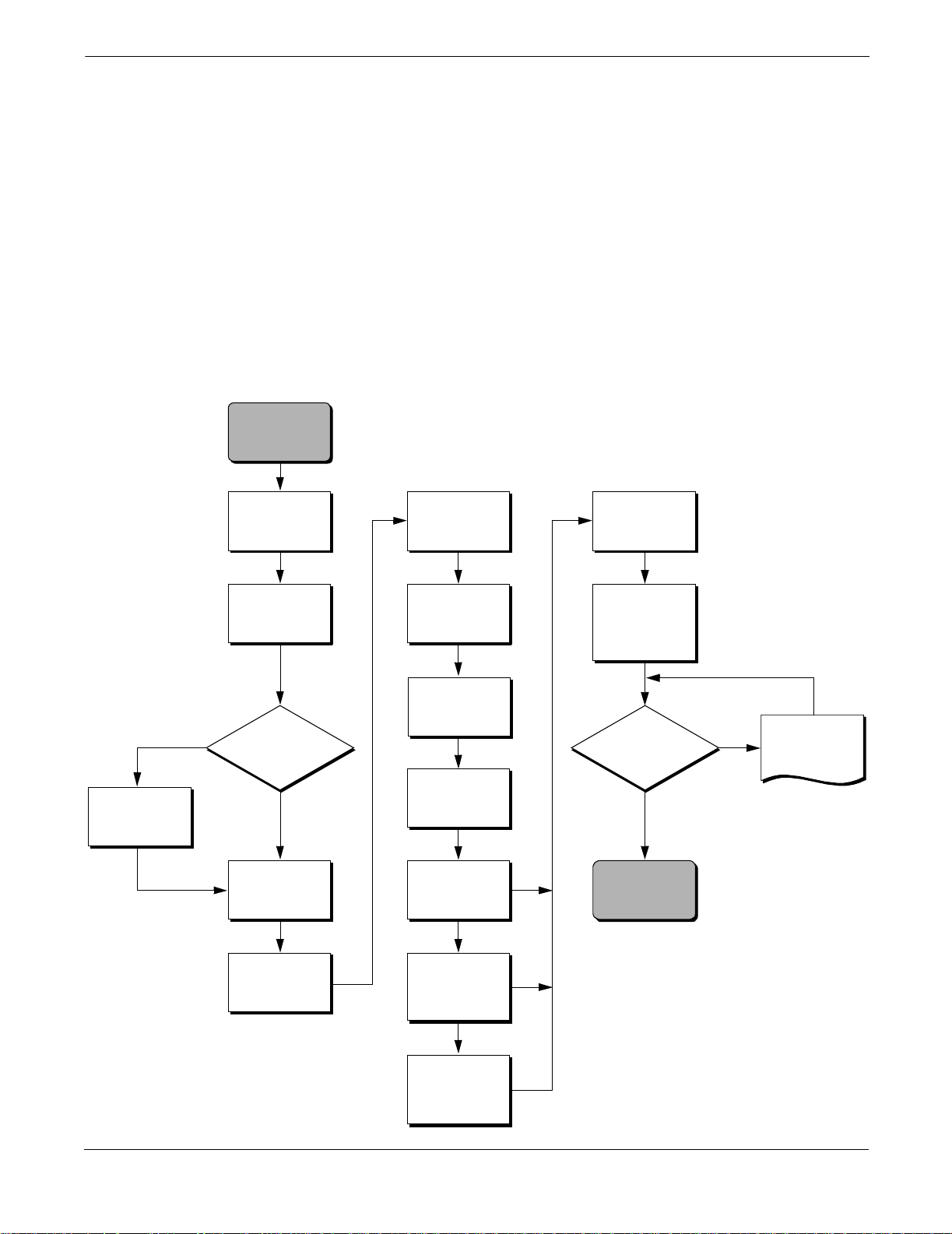
COMMISSIONING: ON THE BENCH OR IN THE LOOP
Figure 2-1. Installation Flowchart.
STA RT
HERE
Bench
Calibration?
Yes
BASIC SETUP VERIFY FIELD INSTALL
Set Units
The transmitter may be commissioned before or after installation.
However, it may be useful to commission the transmitter on the bench
before installation to ensure proper operation and to familiarize
yourself with its functionality.
No
Simulate
Sensor Input
Set Jumpers
or Switches
Set Range
Values
Set Sensor
Type
Set Num ber
of Wires
Set Damping
Within
Specifications?
No
Refer to
Section 4 :
Maintenance
Mount the
Transmitter
Yes
Wire the
Transmitter
Power the
Transmitter
Check for
Process Leaks
DONE
2-2
Page 11

Installation
GENERAL CONSIDERATIONS
Electrical temperature sensors such as resistance temperature
detectors (RTDs) and thermocouples (T/Cs) produce low-level signals
proportional to temperature. The Model 3144 and 3244MV transmitters
convert low-level sensor signals to a standard 4–20 mA dc signal that is
relatively insensitive to lead length and electrical noise. This current
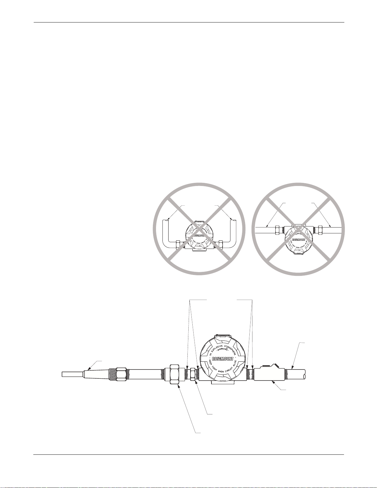
signal is then transmitted to the control room via two wires.
Figures 2-9 and 2-12 show recommended mounting configurations for
transmitters and sensor assemblies. Refer to Section 6: Options for
additional transmitter mounting accessories.
ELECTRICAL CONSIDERATIONS
Proper electrical installation is necessary to prevent errors due to
sensor lead resistance and electrical noise. Shielded cable should be
used for best results in electrically noisy environments. The current
loop must have between 250 and 1100 ohms in order to communicate
with a HART communicator. Refer to Figure 2-4 on page 2-5 for sensor
and current loop connections.
Power Supply To communicate with a transmitter, you will need a 17.75 V dc
minimum power supply. The power supplied to the transmitter should
not drop below the transmitter lift-off voltage (see Figure 2-2). If the
power drops below the lift-off voltage while the transmitter is being
configured, the transmitter may interpret the configuration
information incorrectly.
Figure 2-2. Load Limits.
The dc power supply should provide power with less than 2% ripple.
The total resistance load is the sum of the resistance of the signal leads
and the load resistance of any controller, indicator, or related piece of
equipment in the loop. Note that the resistance of intrinsic safety
barriers, if used, must be included.
NOTE
Do not allow the voltage to drop below 12.0 V dc at the transmitter
terminals when changing transmitter configuration parameters, or
permanent damage to the transmitter could result.
Maximum Load = 43.5 3 (Supply Voltage – 12.0)
1322
1100
1000
750
500
Load (Ohms)
250
0
10
4–20 mA dc
Operating
Region
20 30 40 42.4
12.0
Supply Voltage (V dc)
2-3
Page 12
Rosemount Model 3144 and 3244MV Smart Temperature Transmitters
Field Wiring All power to the transmitter is supplied over the signal wiring. Signal
wiring does not need to be shielded, but twisted pairs should be used for
the best results. Do not run unshielded signal wiring in conduit or open
trays with power wiring, or near heavy electrical equipment. High
voltage may be present on the leads and may cause electrical shock.
To power the transmitter, follow the steps below.
1. Remove the transmitter covers. Do not remove the transmitter
covers in an explosive atmosphere when the circuit is alive.
2. Connect the positive power lead to the terminal marked “+” and
the negative power lead to the terminal marked “–” as shown in
Figure 2-3. When wiring to screw terminals, the use of crimped
lugs is recommended.
3. Tighten the terminal screws to ensure that good contact is made.
No additional power wiring is required.
4. Replace the transmitter covers. Both transmitter covers must be
fully engaged to meet explosion-proof requirements.
NOTE
Do not apply high voltage (e.g., ac line voltage) to the transmitter
terminals. Abnormally high voltage can damage the unit.
Figure 2-3. Transmitter Ter minal Block.
Power/Current Loop
Connections
Sensor Terminals
Negative Terminal
Positive Terminal
Test Terminal
Ground Term inal
3144-0200E01D
Use ordinary copper wire of sufficient size to ensure that the voltage
across the transmitter power terminals does not go below 12.0 V dc.
1. Connect the current signal leads as shown in Figure 2-4.
2. Recheck the polarity and correctness of connections.
3. Turn the power ON.
For information about multichannel installations, refer to page 2-6. For
information about intrinsically safe installations, refer to page 2-13.
See “Safety Messages” on page 2-1 for complete war ning informatio n.
2-4
Page 13
Figure 2-4. Connecting a
Communicator to a Transmitter Loop.
Power/Signal
Terminals
Installation
NOTE
Do not connect the power/signal wiring to the test terminals.
The voltage present on the power/signal leads may burn out the
reverse-polarity protection diode that is built in to the test terminal. If
the test terminals’ reverse polarity protection diode is burned out by the
power/signal wiring, the transmitter can still be operated by jumping
the current from one test terminal to the other.
The signal loop may be grounded at any
point or left ungrounded.
≤RL≤1100 V
250 V
A HART communicator may be
connected at any termination
point in thesignal loop. The
signal loop must have between
250 and 1100 ohms load for
communications.
Power
Supply
Grounding Transmitters are electrically isolated to 500 V ac rms. You can ground
the signal wiring at any single point, if desired. When using a grounded
thermocouple, the grounded junction serves as this point.
NOTE
Do not ground the signal wire at both ends.
Shielded Wire Recommended grounding techniques for shielded wire usually call for a
single grounding point for each shielded wire to avoid grounding the
loop. The following two examples employ the single point grounding
technique:
Example 1
Connect the shield for the signal wiring to the shield for the sensor
wiring. Make sure that the two shields are tied together and
electrically isolated from the transmitter housing. Ground the shield
at the power supply end.
3144-0000A04A
Example 2
Connect the shield for the sensor wiring to the ground terminal
inside of the terminal compartment of the transmitter housing. The
shield for the signal wiring should be cut and isolated from the
transmitter housing. This shield should be grounded only at the
power supply end. Never connect the shield for the signal wiring to
the ground terminal inside the transmitter housing.
2-5
Page 14
Rosemount Model 3144 and 3244MV Smart Temperature Transmitters
Transmitter Housing Ground the transmitter housing in accordance with local electrical
requirements. An internal ground terminal is standard. An optional
external ground lug assembly (Option Code G1) can also be ordered if
needed. Ordering certain hazardous approvals automatically includes
an external ground lug (see table on page 5-9). External grounding is
recommended when using the optional transient protector (Option
Code T1).
Surges/Transients The transmitter will withstand electrical transients of the energy level
usually encountered in static discharges or induced switching.
However, high-energy transients, such as those induced in wiring from
nearby lightning strikes, can damage both the transmitter and the
sensor.
To protect against high-energy transients, install either the integral
transient protection board (Option Code T1) or the Rosemount Model
470 Transient Protector. The integral transient protection board is
available as an ordered option or as an accessory. Refer to “Transient
Protection (Option Code T1)” on page 6-4 for more information. The
Model 470 transient protector is available only as an accessory. Refer to
the Model 470 Transient Protector Product Data Sheet (Rosemount
publication no. 00813-0100-4191) for more information.
Multichannel Installations You can connect several transmitters to a single master power supply,
as shown in Figure 2-5. In this case, the system may be grounded only
at the negative power supply terminal. In multichannel installations
where several transmitters depend on one power supply, and the loss of
all transmitters would cause operational problems, consider an
uninterruptible power supply or a back-up battery. The diodes shown in
Figure 2-5 prevent unwanted charging or discharging of the back-up
battery.
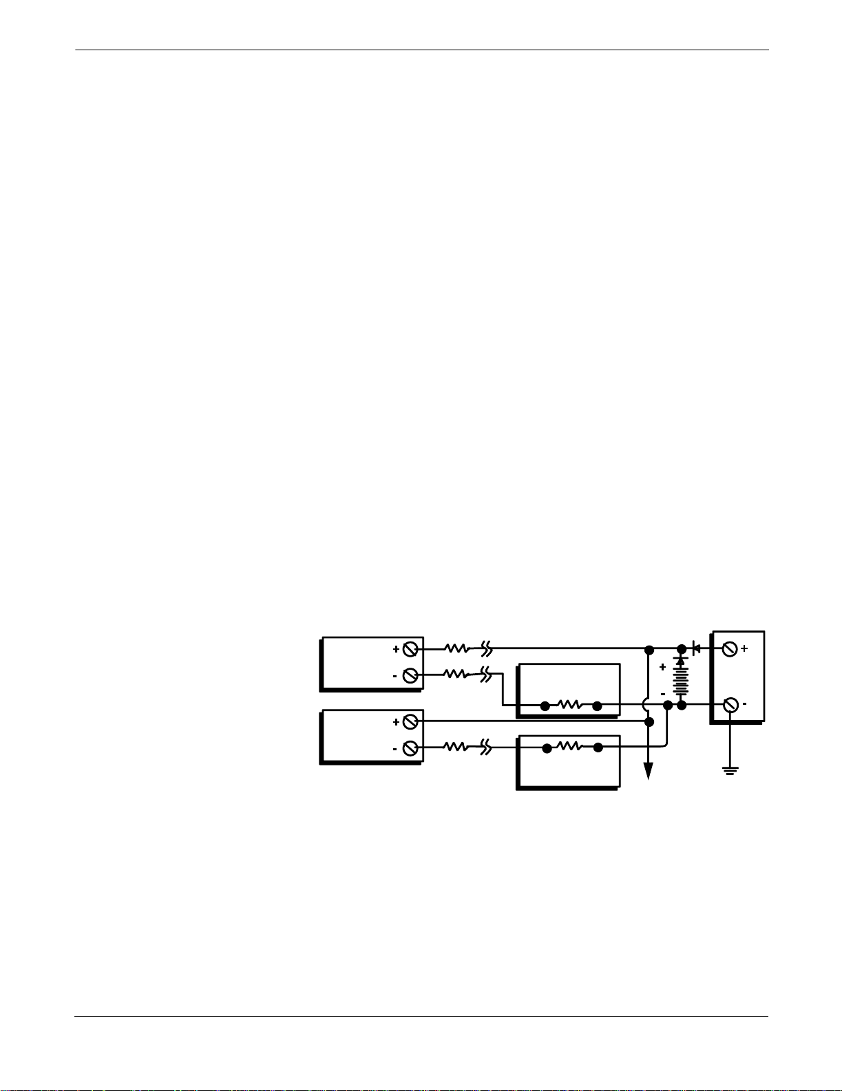
Figure 2-5. Multichannel Installations.
Battery
Backup
dc
Power
Supply
To Additional
Transmitters
Transmitter
No. 1
Transmitter
No. 2
R
R
R
Lead
Lead
Lead
Readout or
Controller No. 1
Readout or
Controller No. 2
Between 250 and
1100 Ω If No Load
Resistor
3044-0131A
2-6
Page 15
Installation
FAILURE MODE AND SECURITY JUMPERS
Failure Mode Jumper The transmitter monitors itself during normal operation with an
automatic diagnostic routine. If the diagnostic routine detects a sensor
failure or a failure in the transmitter electronics, the transmitter goes
into alarm (high or low, depending on the position of the failure mode
jumper).
The analog alarm and saturation values that the transmitter uses
depend on whether it is factory configured to standard or
NAMUR-compliant operation. The values for each are as follows:
Standard Operation
Fail High 21.0 mA ≥ I ≥ 23.0 mA
High Saturation I ≥ 20.5 mA
Low Saturation I ≤ 3.90 mA
Fail Low I ≤ 3.75 mA
NAMUR-Compliant Operation
Fail High 21.0 mA ≥ I ≥ 23.0 mA
High Saturation I ≥ 20.5 mA
Low Saturation I ≤ 3.8 mA
Fail Low I ≤ 3.6 mA
Failure Mode Jumper Locations Without a meter installed:
The failure mode jumper is located on the front side of the
electronics module on the electronics side of the transmitter
housing, and is labeled FAIL MODE (see Figure 2-6 on page 2-8).
With a meter installed:
The failure mode jumper is located on the LCD faceplate on the
electronics module side of the transmitter housing, and is labeled
FAIL MODE (see Figure 2-6 on page 2-8).
Transmitter Security
Jumper
The transmitter is equipped with a write-protect jumper that can be
positioned to prevent the accidental or deliberate change of
configuration data. The security jumper is located on the front side of
the electronics module and is labeled XMTR SECURITY (see Figure 2-6
on page 2-8).
Changing the Position of
the Failure Mode or
Security Jumper
To change the position of the failure mode or security jumper, follow the
steps below.
1. If the transmitter is installed, set the loop to manual.
2. Remove the housing cover on the electronics side. Do not remove
the transmitter cover in explosive atmospheres when the circuit
is alive.
3. Set the jumper(s) to the desired position. See Figure 2-6 on
page 2-8.
4. Replace the transmitter cover. Both transmitter covers must be
fully engaged to meet explosion-proof requirements.
See “Safety Messages” on page 2-1 for complete warning information.
2-7
Page 16

Rosemount Model 3144 and 3244MV Smart Temperature Transmitters
Figure 2-6. Transmitter Jumper
Locations.
Security Jumper
Failure Mode Jumper
(without a Meter Installed)
Failure Mode Jumper
(with a Meter Installed)
SENSOR CONNECTIONS Figure 2-7 on page 2-9 shows the correct input connections to the
sensor terminals on the transmitter. To ensure an adequate sensor
connection, anchor the sensor lead wires beneath the flat washer on the
terminal screw. Do not remove the transmitter cover in explosive
atmospheres when the circuit is alive. Both transmitter covers must be
fully engaged to meet explosion-proof requirements. Use extreme
caution when making contact with the leads and terminals.
RTD or Ohm Inputs If the transmitter is mounted remotely from a 3- or 4-wire RTD, it will
operate within specifications, without recalibration, for lead wire
resistances of up to 10 ohms per lead (equivalent to 1,000 feet of 20
AWG wire). In this case, the leads between the RTD and transmitter
should be shielded. If using only two leads (or a compensation loop lead
wire configuration), both RTD leads are in series with the sensor
element, so significant errors can occur if the lead lengths exceed one
foot of 20 AWG wire. For longer runs, attach a third or fourth lead as
described above.
3144-0200G01A, 2352A01D
Thermocouple or Milliv olt
Inputs
For direct-mount applications, connect the thermocouple directly to the
transmitter. If mounting the transmitter remotely from the sensor, use
appropriate thermocouple extension wire. Make connections for
millivolt inputs with copper wire. Use shielding for long runs of wire.
NOTE
The use of two grounded thermocouples with a Model 3244MV
transmitter is not recommended. For applications in which the use of
two thermocouples is desired, connect either two ungrounded
thermocouples, one grounded and one ungrounded thermocouple, or one
dual element thermocouple.
See “Safety Messages” on page 2-1 for complete warning information.
2-8
Page 17
Figure 2-7. Sensor Wiring Diagram.
Installation
MODEL 3144 SENSOR CONNECTIONS
2-wire RTD
2-wire RTD
2-wire RTD
and Ohms**
and Ohms**
and Ohms
3-wire RTD
3-wire RTD
3-wire RTD
and Ohms**
and Ohms**
and Ohms**
4-wireRTD
and Ohms
T/Cs and Millivolts RTD with
Compensation Loop*
MODEL 3244MV SENSOR CONNECTIONS
2-wire RTD
2-wire RTD
and Ohms**
and Ohms
***
Hot Backup/Dual Sensor with
* Transmitter must be configured for a 3-wireRTD in order to recognize an RTD with a compensation loop.
** Rosemount provides 4-wire sensors for all single-element RTDs. Y oucan use these RTDs in 3-wire configurations by leaving
*** Typicalwiring config uration of a Rosemountdual-elementRTD is shown (R=Red,W=White, G=Green,B=Black).
W
R
Avg. Temp/DT/
the unneeded leads disconnected and insulated with electrical tape.
W&G
G
B
2RTDs**
MECHANICAL CONSIDERATIONS
3-wire RTD
and Ohms**
Avg. Temp/DT/
Hot Backup/Dual Sensor with
2 thermocouples
Use the following information when preparing the installation site and
selecting transmitter options.
4-wire RTD
and Ohms
Avg. Temp/DT/
Hot Backup/Dual Sensor with
RTDs/thermocouples**
T/Cs and Millivolts
Avg. Temp/DT/
Hot Backup/Dual Sensor with
RTDs/thermocouples**
Compensation Loop*
Hot Backup/Dual Sensor
with2RTDswith
Compensation Loop**
The transmitter may be mounted directly to or remotely from the
sensor. Using optional mounting brackets, the transmitter may be
mounted to a flat surface or to a two-inch diameter pipe (see Figure 2-8
on page 2-10).
RTD with
Avg. Temp/∆T/
3144-0000E05A, F05A, A04A
Mounting The transmitter may require supplementary support under
high-vibration conditions, particularly if used with extensive
thermowell lagging or long extension fittings. Pipe-stand mounting,
using one of the optional mounting brackets, is recommended for use in
high-vibration conditions.
Access Requirements Take into account the need for access to the transmitter when choosing
an installation location and position.
Housing Rotation You may rotate the electronics housing up to 90 degrees in either
direction to improve field access to the two compartments.
Terminal Side of Electronics
Housing
Mount the transmitter so the terminal side is accessible. Be sure to
allow adequate clearance for cover removal. Make wiring connections
through the conduit openings on the bottom of the housing.
2-9
Page 18

Rosemount Model 3144 and 3244MV Smart Temperature Transmitters
Circuit S ide of Electronics
Housing
Figure 2-8. Option Code B4 Mounting
Bracket.
PANEL MOU NT
3.65 ±0.06
(2)5/16-inch Bolts not provided
Mount the transmitter so that the circuit side is accessible. Be sure to
provide adequate clearance for cover removal. Also, be sure to account
for extra room if an LCD meter is installed. Refer to Section 6: Options
for more information on the LCD meter option.
PIPE M OUNT
1.04 (26)
1.55
(39.4)
1.0
(25.4)
2.81 ±0.03
NOTE
Dimensions are in inches (millimeters).
Figure 2-9. Option Code B5 Mounting
Bracket.
6.4 (163)
(71.4)
2.0 ± 0.03
(50.8)
0.41 (10.4)
Diameter
0.375 (9.5)
Diameter
2-inch
Pipestand
3144-3144A14A, 0000A01A; 3044-2101A01A; 3144-1081A01B
1.0 (25)
7.2 (182
2-10
3144-0427B, 0427C
Page 19
Installation
ENVIRONMENTAL CONSIDERATIONS
Temperature Effects The transmitter will operate within specifications for ambient
temperatures between –40 and 185 °F (–40 and 85 °C). Heat from the
process is transferred from the thermowell to the transmitter housing.
If the expected process temperature is near or beyond specification
limits, consider the use of additional thermowell lagging, an extension
nipple, or a remote mounting configuration to isolate the transmitter
from the process. Figure 2-11 describes the relationship between
transmitter housing temperature rise and extension length.
Figure 2-10. Model 3144/3244MV
Transmitter Housing Temperature Rise
versus ExtensionLength for a Test
Installation.
HOUSING TEMPERATURE RISE
ABOVE AMBIENT °C (°F)
22
60 (108)
50 (90)
40 (72)
30 (54)
20 (36)
10 (18)
Transmitter Housing
Temperature Risevs.
8
1
5
°
C
(
1
,
5
0
0
°
C
0°
°
F
)
O
(
1
,
0
0
0
°
F)
O
C
(
4
8
2
°
F
)
5
4
0
2
5
Extension Length for a
Test Installation
v
e
n
T
e
mp
e
r
a
v
en
T
e
m
p
e
r
O
v
e
n
T
e
m
p
t
u
r
e
a
t
u
r
e
e
r
a
t
u
r
e
0
3 4 5 6 7 8 9
3.6
EXTENSION LENGTH (IN.)
EXAMPLE:
The maximum permissible housing temperature rise (T) can be
calculated by subtracting the maximum ambient temperature (A)
from the transmitter’s ambient temperature specification limit (S).
For instance, suppose A = 40 °C.
TSA–=
T 85 °C 40 °C–=
T 45 °C=
For a process temperature of 540 °C (see Figure 2-10), an extension
length of 3.6 inches yields a housing temperature rise (R) of 22 °C,
which provides a safety margin of 23 °C. A six-inch extension length
(R = 10 °C) would offer a higher safety margin (35 °C) and would
reduce temperature-effect errors but would probably require extra
support for the transmitter. Gauge the requirements for individual
applications along this scale. If a thermowell with lagging is used,
the extension length may be reduced by the length of the lagging.
3044-0123A
2-11
Page 20
Rosemount Model 3144 and 3244MV Smart Temperature Transmitters
Moist or Corrosive
Environments
Figure 2-11. Incorrect Conduit
Installation.
The Model 3144 and 3244MV transmitters have a highly reliable
dual compartment housing designed to resist attack by moisture and
corrosives. The sealed electronics module is mounted in a
compartment that is isolated from the terminal side conduit entries.
O-ring seals protect the interior when the covers are installed. In
humid environments, however, it is possible for moisture to
accumulate in conduit lines and drain into the housing.
Proper transmitter installation can ensure optimal operation and
service life and prevent moisture from accumulating in the housing.
Refer to Figure 2-11, and Figure 2-12 before mounting a transmitter.
Mount the transmitter at a high point in the conduit run, if possible,
so that moisture from the conduits will not drain into the housing. If
the transmitter is mounted at a low point in the conduit run, the
terminal compartment could fill with water. In some instances, the
installation of a poured conduit seal, such as the one pictured in
Figure 2-12, is advisable. Remove the terminal compartment cover
periodically and inspect the transmitter for moisture and corrosion.
Conduit
Lines
Conduit
Lines
Figure 2-12. Recommended Mounting
with Drain Seal.
Thermowe ll
Sealing
Compound
Sensor Hex
Union Coupling
with Exten sio n
3144-0429A, 04 29B
Conduit for
Field Wiring
Poured ConduitSeal
(Where R equired)
3144-0430B
2-12
Page 21

Installation
Hazardous Locations
Installations
INSTALLATION PROCEDURE
The transmitter is designed with explosion-proof housings and circuitry
suitable for intrinsically safe and non-incendive operation. Each
transmitter is clearly marked with a tag indicating the approvals
carried. To maintain certified ratings for installed transmitters, install
in accordance with all applicable installation codes and approval
drawings. Verify that the operating atmosphere of the transmitter is
consistent with the appropriate hazardous locations certifications. Both
transmitter covers must be fully engaged to meet explosion proof
requirements. Refer to Appendix D: Hazardous Area Approval
Installation Drawings for transmitter installation drawings.
IMPORTANT
Once a device labeled with multiple approval types is installed, it
should not be reinstalled using any of the other labeled approval types.
To ensure this, the approval label should be permanently marked to
distinguish the used from the unused approval type(s).
Installation consists of mounting the transmitter and sensor and
making electrical connections. If you are mounting the transmitter
directly to the sensor assembly, use the process shown in Figure 2-13. If
you are mounting the transmitter apart from the sensor assembly, use
conduit between the sensor and transmitter. The transmitter accepts
male conduit fittings with
(PG 11), or JIS G
perform the installation.
1
/2 threads. Make sure only qualified personnel
1
/2–14 NPT, M20 × 1.5 (CM 20), PG 13.5
Typical North American
Configuration
1. Mount the thermowell to the pipe or process container wall. Be
sure to install and tighten thermowells and sensors. Perform a
leak check before starting the process.
2. Attach any necessary unions, couplings, and extension fittings.
Be sure to seal the fitting threads with silicone or tape (if
required).
3. Screw the sensor into the thermowell.
4. Verify all sealing requirements for severe environments or to
satisfy code requirements.
5. Attach the transmitter to the thermowell assembly. Be sure to
seal all threads with silicone or tape (if required).
6. Pull sensor leads through the extensions, unions, or couplings
into the terminal side of the transmitter housing.
7. Install conduit for field wiring to the remaining conduit entry of
the transmitter.
8. Pull the field wiring leads into the terminal side of the
transmitter housing. Avoid contact with the leads and terminals.
9. Attach the sensor leads to the transmitter sensor terminals.
Attach the power leads to the transmitter power terminals. Avoid
contact with the leads and terminals.
10. Attach and tighten both transmitter covers. Both transmitter
covers must be fully engaged to meet explosion-proof
requirements.
See “Safety Messages” on page 2-1 for complete warning information.
2-13
Page 22
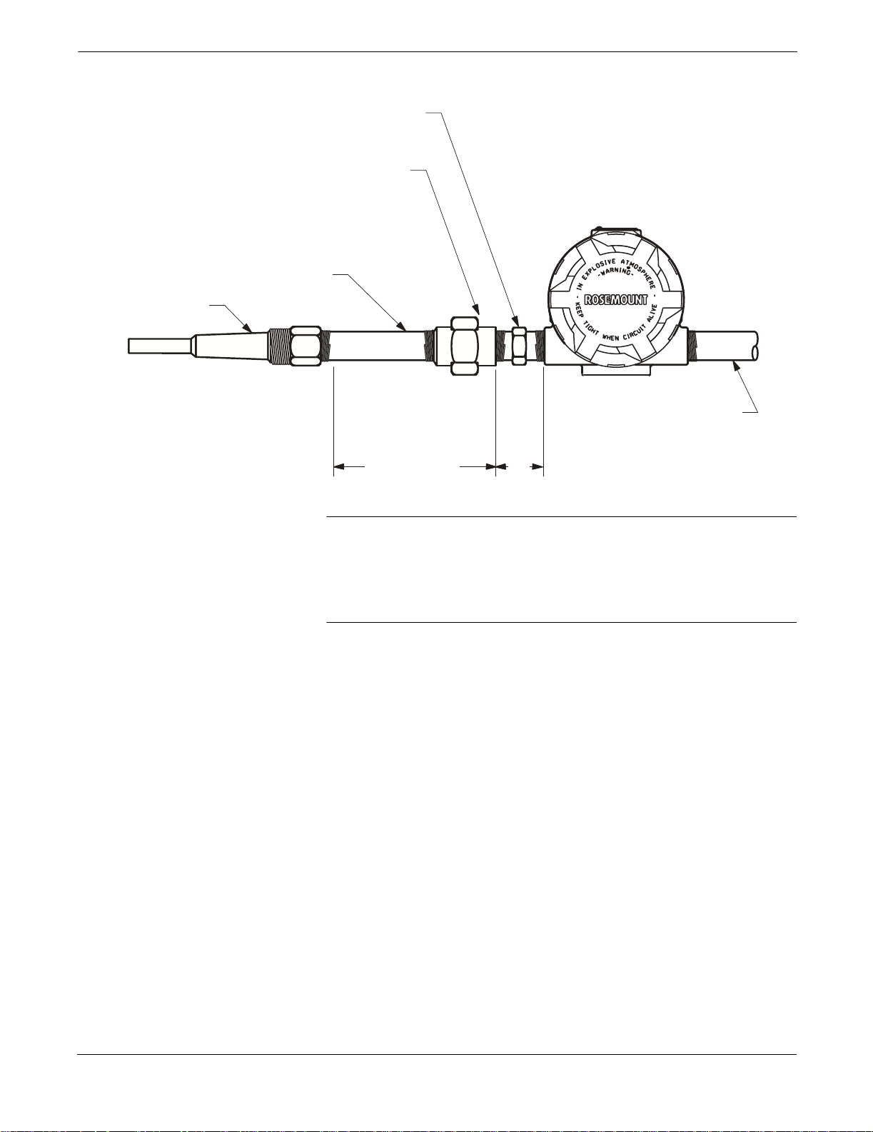
Rosemount Model 3144 and 3244MV Smart Temperature Transmitters
Figure 2-13. Typical North American
Mounting Configuration.
Sensor Hex
Union o r
Coupling
Extension
Thermowell
Conduit for
Field Wiring
(dc power)
NOTE
Dimensions are in inches (millim eters).
Extension Fitting
Length
3.2
(81)
NOTE
The National Electrical Code requires that a barrier or seal be used in
addition to the primary (sensor) seal to prevent process fluid from
entering the electrical conduit and continuing to the control room.
Professional safety assistance is recommended for installations in
potentially hazardous processes.
3144-0433B
2-14
Page 23
Installation
Typical European
Configuration
1. Mount the thermowell to the pipe or the process container wall.
Install and tighten thermowells and sensors. Perform a leak
check before starting the process.
2. Attach a connection head to the thermowell.
3. Insert the sensor into the thermowell and attach it to the
connection head.
4. Mount the transmitter to a 2-inch pipe or a suitable panel using
one of the optional mounting brackets. The B4 bracket is shown
in Figure 2-14.
5. Attach cable glands to the shielded cable running from the
connection head to the transmitter and from the transmitter to
the control room.
6. Insert the shielded cable leads into the connection head and the
transmitter through the cable entries. Connect and tighten the
cable glands.
7. Connect the shielded cable leads to the sensor wiring leads inside
of the connection head, and the sensor wiring terminals inside of
the transmitter housing. Avoid contact with the leads and the
terminals.
8. Connect the shielded cable leads to the transmitter power
terminals. Avoid contact with the leads and the terminals.
Figure2-14.TypicalEuropeanProcess
Mounting Configuration.
Cable Gland
Shielded Cable from
Sensor to Transmitter
Shielded Cable
from Transmitter
to Control Room
2-inch
Pipe
B4
Mounting
Bracket
644-0000B05B
See “Safety Messages” on page 2-1 for complete warning information.
2-15
Page 24
Rosemount Model 3144 and 3244MV Smart Temperature Transmitters
INSTALLATION IN
CONJUNCTION WITH A
MODEL 333 HART
TRI-LOOP
HART-TO-ANALOG
SIGNAL CONVERTER
Figure2-15.HARTTri-Loop Installation
Flowchart.
START
HERE
Unpack the
Tri-Loop
Use the Model 3244MV transmitter in operation with two sensors in
conjunction with a Model 333 HART Tri-Loop
®
HART-to-Analog Signal
Converter to acquire an independent 4–20 mA analog output signal for
each sensor input. During normal operation, the Model 3244MV
transmitter outputs four out of the five following digital process
variables: sensor 1, sensor 2, differential temperature, average
temperature, and transmitter terminal temperature. The HART
Tri-Loop divides the digital signal and outputs any or all of these
variables into as many as three separate 4–20 mA analog channels.
Refer to Figure 2-15 for basic installation information. Refer to the
Model 333 HART Tri-Loop HART-to-Analog Signal Converter Product
Manual (Rosemount publication number 00809-0100-4754) for
complete installation information.
INSTALL THE
TRI-LOOP
COMMISSION
THE TRI-LOOP
No
Install the
Model 3244MV
(see page 2-2)
Review the
Tri-Loop
Product Manual
Model 3244MV
Installed?
Yes
Set theModel
3244MV Burst
Command
Order
Set theModel
3244M V to
Burst HART
Command3
ReviewTri-Loop
Installation
Conside r ations
Mount the
Tri-Loop to a
DIN Rail
RunWiresfrom
Model 3244MV
to Burst Input
Terminals
Install Channel 1
Wires fro m
Tri-Loop to
Control Room
OPTIONAL:
Install Channel 2
Wires fro m
Tri-Loop to
Control Room
Configure the
Tri-Loop to
Receive Model
3244MVBurst
Commands
Pass System
Test?
Yes
DONE
No
Refer to th e
HART Tri-Loop
Product Manual
2-16
OPTIONAL:
Install Channel 3
Wires fro m
Tri-Loop to
Control Room
Page 25

Installation
COMMISSIONING THE TRANSMITTER FOR USE WITH THE HART TRI-LOOP
Set the Transmitter to Burst
Mode
To prepare the Model 3244MV transmitter for use with a Model 333
HART Tri-Loop, you must configure the transmitter to Burst Mode and
set the process variable output order. In Burst Mode, the transmitter
provides digital information for the analog current in mA to the HART
Tri-Loop. The HART Tri-Loop divides the signal into separate 4–20 mA
loops for the primary (PV), secondary (SV), tertiary (TV), and
quaternary (QV) variables. When using the Model 3244MV transmitter
in conjunction with the HART Tri-Loop, you must also consider the
configuration of the differential temperature and Hot Backup features,
if used.
NOTE
These procedures assume that the sensors and the transmitter are
connected, powered, and functioning properly, and that a Model 275
HART Communicator is connected to the transmitter control loop and
is communicating successfully. For communicator usage instructions,
see Appendix B: Model 275 HART Communicator.
To set the transmitter to burst mode, follow the steps below.
1. From the Home screen, select 1 Device setup, 4 Detailed setup,
3 Output condition, 2HART output, 4 Burst option to prepare to
set the transmitter to burst command 3. The communicator
displays the Burst option screen.
Set Process Variable Output
Order
2. Select Process vars/crnt. The communicator returns to the HART
output screen.
3. Select 3Burst mode to prepare to enable Burst Mode. The
communicator displays the Burst Mode screen.
4. Select On to enable Burst Mode. The communicator returns to
the HART output screen.
5. Select Send to download the new configuration information to
the transmitter.
To set the process variable output order, follow the steps below.
1. From the Home screen, select 1 Device setup, 1 Process variables,
7 Variable re-map. Select OK to set the control loop to manual.
The communicator displays the Primary Variable screen.
2. Select the item you wish to set as the primary variable at the
Select PV prompt.
3. Repeat step 2 for the SV, TV, and QV. The communicator displays
the Variable mapping screen.
4. Select OK to accept the order to which the variables are mapped,
or Abort to abort the entire procedure.
NOTE
Take careful note of the process variable output order. You must
configure the HART Tri-Loop to read the variables in the same order.
5. Select OK to return the control loop to automatic control.
2-17
Page 26

Rosemount Model 3144 and 3244MV Smart Temperature Transmitters
Special Considerations To initiate operation between a Model 3244MV transmitter and the
HART Tri-Loop, you must consider the configuration of both the
differential temperature and the Hot Backup features, if used.
Differential Temperature Measurement
To enable the differential temperature measurement feature of a
Model 3244MV transmitter operating in conjunction with the HART
Tri-Loop, adjust the range end points of the corresponding channel
on the HART Tri-Loop to include zero. For example, if you wish the
secondary variable of the transmitter to report differential
temperature, configure the transmitter accordingly (see “Set Process
Variable Output Order” on page 2-17), and adjust the corresponding
channel of the HART Tri-Loop so one range end point is negative
and the other is positive.
Hot Backup
To enable the Hot Backup feature of a Model 3244MV transmitter
operating in conjunction with the HART Tri-Loop, ensure that the
output units of the sensors are the same as the units of the HART
Tri-Loop. You may use any combination of RTDs or thermocouples
as long as the units of both match the units of the HART Tri-Loop.
For more information on configuring the transmitter for Hot
Backup, see page 3-10. See ”Using the Tri-Loop to Detect Sensor
Failures and Sensor Drift” for information on how to use the
Tri-Loop to detect sensor failure and sensor drift.
Using the Tri-Loop to Detect
Sensor Failures and Senso r Drift
The Model 3244MV transmitter outputs a digital HART signal
whenever a sensor failure occurs. If an analog warning is required, the
HART Tri-Loop can be configured to produce an analog signal that can
be interpreted by the control system as a sensor failure.
To set up the HART Tri-Loop to transmit sensor failure alerts, follow
the steps below.
1. Configure the Model 3244MV transmitter variable map as shown
in the table.
Variable Mapping
PV Sensor1 or Sensor Average
SV Sensor2
TV Differential Temperature
QV As Desired
2. Configure Channel 1 of the HART Tri-Loop as TV (differential
temperature). If either sensor should fail, the differential
temperature output will be +9999 or –9999 (high or low
saturation), depending on the position of the Failure Mode
Jumper (see “Failure Mode and Security Jumpers” on page 2-7).
3. Select temperature units for Channel 1 that match the
differential temperature units of the transmitter.
2-18
Page 27

Figure 2-16. Tracking Sensor Drift and
Sensor Failure with Differential
Temperature.
Installation
4. Specify a range for the TV such as –100 to 100 °C. If the range is
large, then a sensor drift of a few degrees will represent only a
small percent of range. If Sensor 1 or Sensor 2 fails, the TV will
be +9999 (high saturation) or –9999 (low saturation). In this
example, zero is the midpoint of the TV range. If a ∆T of zero is
set as the lower range limit (4 mA), then the output could
saturate low if the reading from Sensor 2 exceeds the reading
from Sensor 1. By placing zero in the middle of the range, the
output will normally stay near 12 mA, and the problem will be
avoided.
5. Configure the DCS so that TV < –100 °C or TV > 100 °C indicates
a sensor failure and, for example, TV ≤ –3 °C or TV ≥ 3°C
indicates a drift alert. See Figure 2-16.
Sensor Failure
(Failure Mode Jumper HI)
100 °C
Sensor Drift
3°C
0°C
–3 ° C
DIFFERENTIAL TEMPERATURE
–100 °C
Sensor Drift
Sensor Failure
(Failure Mode Jum per LO)
2-19
Page 28

Rosemount Model 3144 and 3244MV Smart Temperature Transmitters
2-20
Page 29

Section
3 On-line Operations
OVERVIEW This section contains information needed to configure and format the
Model 3144 and 3244MV Smart Temperature Transmitters. The
transmitters can be configured either on-line or off-line. During on-line
configuration, the transmitter is connected to a HART communicator.
Data are entered in the working register of the communicator and sent
directly to the transmitter. Off-line configuration consists of storing
configuration data in a HART communicator while it is not connected to
a transmitter. Data is stored in nonvolatile memory and can be
downloaded to the transmitter at a later time.
NOTE
The information in this section applies to the use of a Model 275 HART
Communicator to communicate with a Model 3144 or 3244MV Smart
Temperature Transmitter. For information regarding the use of a Model
268 Communicator, refer to Appendix C: Model 268 SMART FAMILY
Interface.
SAFETY MESSAGES Instructions and procedures in this section may require special
precautions to ensure the safety of the personnel performing the
operations. Information that raises potential safety issues is indicated
by a warning symbol ( ). Please refer to the following safety messages
before performing an operation preceded by this symbol.
Warnings
Explosions may result in death or serious injury.
• Do not remove the instrument cover in explosive atmospheres when the circuit
is alive.
• Before connecting a HART communicator in an explosive atmosphere, make
sure the instruments in the loop are installed in accordance with intrinsically
safe or non-incendive field wiring practices.
• Bothtransmitter covers must be fully engaged to meet explosion proof
requirements.
Electrical shock could cause death or serious injury. If the sensor is installed in a
high-voltage environment and a fault or installation error occurs, high voltage may
be present on transmitter leads and terminals.
• Use extreme caution when making contact with the leads and terminals.
3-1
Page 30

Rosemount Model 3144 and 3244MV Smart Temperature Transmitters
Setting the Loop to Manual Whenever you are preparing to send or request data that would disrupt
the loop or change the output of the transmitter, you must set your
process application loop to manual. Both the Model 275 HART
Communicator and the Rosemount Model 268 SMART FAMILY
Interface will prompt you to set the loop to manual when necessary.
Keep in mind that acknowledging this prompt does not set the loop to
manual. The prompt is only a reminder; you have to set the loop to
manual yourself, as a separate operation.
REVIEW CONFIGURATION DATA
Review all of the factory-set configuration data to ensure that it reflects
the current application before operating the Model 3144 or 3244MV
transmitters in an actual installation.
Review Review the transmitter configuration parameters set at the factory to
HART Fast Keys 1, 5
ensure accuracy and compatibility with your particular application.
After activating the Review function, scroll through the data list to
check each variable. Refer to “Basic Setup” on page 3-5 if a change to
the transmitter configuration data is necessary.
CHECK OUTPUT Before performing other transmitter on-line operations, review the
digital output parameters to ensure that the transmitter is operating
properly and is configured to the appropriate process variables.
Proces s V ariab les The process variables for the Model 3144 and 3244MV transmitters
HART Fast Keys 1, 1
provide the transmitter output. The Process Variable menu displays
process variables and allows for remapping of the values shown. These
process variables are continuously updated. Select Variable Re-map to
change the sequencing of the process variables. With the Model 3144,
two screens follow that allow you to select the primary variable (PV)
and the secondary variable (SV). From each screen you can choose
either sensor 1 or terminal temperature. With the Model 3244MV, four
screens follow that allow you to select the primary variable (PV),
secondary variable (SV), tertiary variable (TV), and quaternary
variable (QV). Primary variable choices include sensor 1, sensor 2,
differential temperature, average temperature, and transmitter
terminal temperature. The primary variable is the 4–20 mA analog
signal.
3-2
See Tables 3-1, 3-2, and 3-3 for a list of interaction rules for varying
transmitter configurations.
Page 31

TABLE 3-1. Valid Options/Outputs Using Sensor 1 (Model 3144 and 3244MV).
On-line Operations
Diff
Primary
Variable
Any Y Y/N Y/N Y/N Y/N Invalid
Any Y/N Y Y/N Y/N Y/N Invalid
Sensor 2 Y/N Y/N Y/N Y/N Y/N Invalid
Differential N N Y/N N Y/N Differential None ±9999 Normal Normal 9999 ±9999
Any N N Y/N Y Y/N Alarm Sensor1Fail ±9999 Normal ±9999 9999 ±9999
Term Temp N N Y/N N Y/N Term Temp None ±9999 Normal Normal 9999 ±9999
Sensor 1 N N Y/N N Y/N Sensor 1 None ±9999 Normal Normal 9999 ±9999
Average N N Y/N N Y/N Average None ±9999 Normal Normal 9999 ±9999
Hot Backup
Enabled
Drift Alert
Activated
Drift Alarm
Mode On
Sensor 1 Fail
Analog
Output
Sensor 2 Fail
Digital
Status
Temp
Value
Term
Temp
Value
Sensor
1
Value
Sensor
2
Value
Average
Temp
Value
NOTE: If alarm value is set to low, the valuewill be –9999, and if set to high the value will be +9999.
NOTE: If a hardware error occurs, alloutputs will go to ±9999.
TABLE 3-2. Valid Options/Outputs Using Sensor 2 (Model 3244MV Only).
Primary
Variable
Any Y Y/N Y/N Y/N Y/N Invalid
Any Y/N Y Y/N Y/N Y/N Invalid
Sensor 1 Y/N Y/N Y/N Y/N Y/N Invalid
Differential N N Y/N Y/N N Differential None ±9999 Normal 9999 Normal ±9999
Any N N Y/N Y/N Y Alarm Sensor 1 Fail ±9999 Normal 9999 ±9999 ±9999
Term Temp N N Y/N Y/N N Term Temp None ±9999 Normal 9999 Normal ±9999
Sensor 2 N N Y/N Y/N N Sensor 2 None ±9999 Normal 9999 Normal ±9999
Average N N Y/N Y/N N Average None ±9999 Normal 9999 Normal ±9999
Hot Backup
Enabled
Drift Alert
Activated
Drift Alarm
Mode On
Sensor 1 Fail
Analog
Output
Sensor 2 Fail
Digital
Status
Diff
Temp
Value
NOTE: If alarm value is set to low, the valuewill be –9999, and if set to high the value will be +9999.
NOTE: If a hardware error occurs, alloutputs will go to ±9999.
Term
Temp
Value
Sensor
1
Value
Sensor
2
Value
Average
Temp
Value
3-3
Page 32

Rosemount Model 3144 and 3244MV Smart Temperature Transmitters
TABLE 3-3. Valid Options/Outputs Using Both Sensor 1 and Sensor 2 (Model 3244MV Only).
Primary
Variable
Diff
Analog
Hot Backup
Enabled
Drift Alert
Activated
Drift Alarm
Mode On
Sensor 1 Fail
Output
Sensor 2 Fail
Digital
Status
Temp
Value
Term
Temp
Value
Sensor
1
Value
Sensor
2
Value
Average
Temp
Value
Differential Y Y/N Y/N Y/N Y/N Invalid
Term Temp Y Y/ N Y /N Y/N Y/N Invali d
Sensor 2 Y Y/N Y/N Y/N Y/N Invalid
Any N N Y/N N Y Alarm Sensor 2 Fail ±9999 Normal Normal ±9999 ±9999
Any N N Y/N Y N Alarm Sensor 1 Fail ±9999 Normal ±9999 Normal ±9999
Any N N Y/N Y Y Alarm Sensor 1/Sensor 2 Fail ±9999 Normal ±9999 ±9999 ±9999
Any N Y N N Y Alarm Drift Alert/Sensor 2 Fail ±9999 Normal Normal ±9999 ±9999
Any N Y N Y N Alarm Drift Alert/Sensor 1 Fail ±9999 Normal ±9999 Normal ±9999
Any N Y N Y Y Alarm Sensor 1/Sensor 2 Fail ±9999 Normal ±9999 ±9999 ±9999
Any N Y Y N N Alarm Drift Alert Normal Normal Normal Normal Normal
Any N Y Y N Y Alarm DriftAlert/Sensor 2 Fail ±9999 Normal Normal ±9999 ±9999
Any NYYYN Alarm DriftAlert/Sensor1Fail±9999Normal±9999Normal±9999
Any N Y Y Y Y Alarm Sensor 1/Sensor 2 Fail ±9999 Normal ±9999 ±9999 ±9999
Differential N N Y/N N N Differential None Normal Normal Normal Normal Normal
Differential N Y N N N Differential Drift Alert Normal Normal Normal Normal Normal
Term Temp N N Y/N N N Term Temp None Normal Normal Normal Normal Normal
Term Temp N Y N N N Term Temp Drift Alert Normal Normal Normal Normal Normal
Sensor1 N N Y/N N N Sensor1 None Normal Normal Normal Normal Normal
Sensor1 N Y N N N Sensor 1 Drift Alert Normal Normal Normal Normal Normal
Sensor1 Y N Y/N N N Sensor 1 None Normal Normal Normal Normal Normal
Sensor1 Y N Y/N N Y Sensor 1 Sensor2Fail ±9999 Normal Normal ±9999 Sens 1
Sensor 1
Sensor 1
(1)
Y N Y/N Y N Sensor 2 Hot BU/Sensor 1 Fail ±9999 Normal ±9999 Normal Sens 2
(1)
Y N Y/N Y Y Alarm HotBU/Sensor 1/Sensor
±9999 Normal ±9999 ±9999 ±9999
2Fail
Sensor1 Y Y N N N Sensor 1 Drift Alert Normal Normal Normal Normal Normal
Sensor 1 Y Y N N Y Sensor 1 Drift Alert/Sensor 2 Fail ±9999 Normal Normal ±9999 Sens 1
Sensor 1
Sensor 1
(1)
Y Y N Y N Sensor 2 DriftAlert/HotBU/Sensor
(1)
Y Y N Y Y Alarm HotBU/Sensor 1/Sensor
1Fail
±9999 Normal ±9999 Normal Sens 2
±9999 Normal ±9999 ±9999 ±9999
2Fail
Any Y Y Y Y/N Y/N Invalid
(2)
Sensor2 N N Y/N N N Sensor2 None Normal Normal Normal Normal Normal
Sensor2 N Y N N N Sensor 2 Drift Alert Normal Normal Normal Normal Normal
Average N N Y/N N N Average None Normal Normal Normal Normal Normal
Average N Y N N N Average Drift Alert Normal Normal Normal Normal Normal
Average Y N Y/N N N Average None Normal Normal Normal Normal Normal
Average Y N Y/N N Y Average Sensor 2 Fail ±9999 Normal Normal ±9999 Sens 1
(1)
Average
Average
Y N Y/N Y N Sensor 2 Hot BU/Sensor 1 Fail ±9999 Normal ±9999 Normal Sens 2
(1)
Y N Y/N Y Y Alarm HotBU/Sensor 1/Sensor
±9999 Normal ±9999 ±9999 ±9999
2Fail
Average Y Y N N N Average Drift Alert Normal Normal Normal Normal Normal
Average Y Y N N Y Average Drift Alert/Sensor 2 Fail ±9999 Normal Normal ±9999 Sens 1
(1)
Average
Average
Y Y N Y N Sensor 2 DriftAlert/HotBU/Sensor
(1)
Y Y N Y Y Alarm HotBU/Sensor 1/Sensor
1Fail
±9999 Normal ±9999 Normal Sens 2
±9999 Normal ±9999 ±9999 ±9999
2Fail
Any N N Y/N N Y Alarm Sensor 2 Fail ±9999 Normal Normal ±9999 ±9999
NOTE: If alarm value is set to low, the valuewill be –9999, and if set to high the value will be +9999.
NOTE: If a hardware error occurs, alloutputs will go to ±9999.
(1) Remapping occurs in thissituation.
(2) Hot Backup and Drift Alarm mode can not be used simultaneosly.
3-4
Page 33

On-line Operations
BASIC SETUP The transmitters must be configured for certain basic variables in order
to be operational. In many cases, all of these variables are
pre-configured at the factory. Configuration may be required if your
transmitter is not configured or if the configuration variables need
revision.
Select Senso r Type The Sensor 1 Conn and Sensor 2 Conn commands designate, for the
HART Fast Keys 1, 3, (5 or 7)
transmitter, the sensor type and the number of wires to be connected.
Note that differential and average temperature measurements can only
be made with 2- or 3-wire sensors. The Sensor 2 Conn command
pertains only to the Model 3244MV transmitter. Select from the
following sensor types:
• 2-, 3-, or 4-wire Pt 100, Pt 200, Pt 500, or Pt 1000 (α = 0.00385)
(1)
platinum RTDs
(1)
• 2-, 3-, or 4-wire Pt 100 α = 0.003916
platinum RTD
• 2-, 3-, or 4-wire Ni 120 nickel RTDs
• 2-, 3-, or 4-wire Cu 10 copper RTDs
• Type B, E, J, K, N, R, S, and T thermocouples
• NIST Type C thermocouple
• –10 to 100 millivolts
• 2-, 3-, or 4-wire 0 to 2000 ohms
• Special RTD or T/C calibration schedules
Set Output Units The PV Unit command sets the desired primary variable units. Set the
HART Fast Keys 1, 3, 2
transmitter output to one of the following engineering units:
• Degrees Celsius
• Degrees Fahrenheit
• Degrees Rankine
• Kelvin
•Ohms
• Millivolts
NOTE
After changing units, press SEND (F2) so the microprocessor will
recalculate the associated variables (4–20 mA points, for example).
Both models recalculate all variables that depend on units. After the
transmitter recalculates the variables, you may change any of the
remaining parameters.
(1) Pt 1000
α =
0.00385 and Pt 100
in previous versions of the Model 3144 and 3244MV transmitters.
α =
0.003916 RTD sensor input types are not available
3-5
Page 34

Rosemount Model 3144 and 3244MV Smart Temperature Transmitters
Rerange The Range Values command sets the 4 and 20 mA points or the lower
HART Fast Keys 1, 3, 3
and upper range values. Setting the range values to the limits of
expected readings maximizes transmitter performance; the transmitter
is most accurate when operated within the expected temperature
ranges for your application. The range of expected readings is defined
by the Lower Range Value (LRV) and the Upper Range Value (URV).
Refer to Table 5-1 on page 5-10 for unit and range limits. You can reset
the transmitter range values as often as necessary to reflect changing
process conditions.
DETAILED SETUP
50/60 Hz Filter The 50/60 Hz filter command sets the transmitter electronic filter to
HART Fast Keys 1,4,1,3
match the frequency of the ac power supply in your plant, which
reduces or eliminates electronic noise within the measurement loop.
Terminal Temperature
Settings
HART Fast Keys 1,4,1,2
The Ter m Te m p S e n s o r command sets the terminal temperature units
to indicate the ambient temperature of the transmitter.
Signal Conditio n The Signal Condition command allows you to view or change primary
HART Fast Keys 1,4,2
variable lower and upper range values, sensor percent range, and
sensor damping.
Analog Output The Analog Output command allows you to view the analog output
HART Fast Keys 1,4,3,1
signal and alarm setting (high or low). With this command you can also
initiate a loop test or make digital trim changes.
Disable Special Sensor The Dis Spec Snsr command disables sensor matching or any other
HART Fast Keys 1,4,1,1,4, (1 or 2), 5
special sensor configuration, and returns the transmitter to either the
factory or user trim setting, whichever was used previously. After
disabling the sp eci al sensor,make certain the trans mitter engineering
units default co rrectly be fore retu rni ng th e transmitter to servi ce .
HART Output The HART Output command allows you to make changes to the
HART Fast Keys 1,4,3,2
multidrop address, specify the number of requested preambles, initiate
burst mode, and make changes to the burst options.
Meter Settings The Meter Settings command sets meter options including engineering
HART Fast Keys 1,4,3,3
units, decimal point, and bar graph features. Transmitters without
meters are shipped set to “UNUSED.” Change the meter settings to
reflect necessary configuration parameters when adding a meter or
re-configuring the transmitter.
3-6
To customize the variables that the meter displays, follow the steps
below.
1. Select 1 Device setup, 4 Detailed setup, 3 Output condition,
3Meter Options, 1Meter typ to prepare to customize the meter
display.
2. Select the appropriate variable configuration from the Meter
Type screen.
Page 35

On-line Operations
NOTE
Selecting Not Used from the Meter Type screen will disable the meter.
3. Select Send to download the new meter configuration to the
transmitter.
For a more detailed description of the meter features and diagnostic
messages, refer to “LCD Meter (Option Code M5)” on page 6-6.
Alarm Values
HART Fast Keys 1,4,3,4
(1)
The Alarm Values command allows the high and low alarm and
saturation values to be viewed. Transmitters are factory configured for
either Rosemount standard or NAMUR-compliant output levels and
cannot be changed in the field. Use the failure mode jumper (see
“Failure Mode and Security Jumpers” on page 2-7) to set whether the
output will be driven to high alarm or low alarm in the case of failure.
Process Variable Damping The PV Damp command changes the response time of the transmitter
HART Fast Keys 1,3,3
to smooth variations in output readings caused by rapid changes in
input. Determine the appropriate damping setting based on the
necessary response time, signal stability, and other requirements of the
loop dynamics of your system. The default damping value is 5.0 seconds
and can be reset to any value between 0 and 32 seconds.
The value chosen for damping affects the response time of the
transmitter. When set to zero (i.e., disabled), the damping function is off
and the transmitter output reacts to changes in input as quickly as the
intermittent sensor algorithm allows (refer to “Intermittent Sensor
Algorithm” on page 5-14). Increasing the damping value increases
transmitter response time.
With damping enabled, if the temperature change is within 2 percent of
the output range, the transmitter measures the change in input every
500 milliseconds and outputs values according to the following
relationship:
2TU–
Damped Value P N–()
P =previous damped value
N =new sensor value
T = damping time constant
U =update rate
× N+=
------------------
2TU+
At the value to which the damping time constant is set, the transmitter
output is at 63 percent of the input change; it continues to approach the
input according to the damping equation above.
For example, as illustrated in Figure 3-1, if the temperature undergoes
a step change—within 2 percent of the output range—from 100 degrees
to 110 degrees, and the damping is set to 5.0 seconds, the transmitter
calculates and reports a new reading every 500 milliseconds using the
damping equation. At 5.0 seconds, the transmitter outputs 106.3
degrees, or 63 percent of the input change, and the output continues to
approach the input curve according to the equation above.
For information regarding the damping function when the input change
is greater than 2 percent of the output range, refer to “Intermittent
Sensor Algorithm” on page 5-14.
(1) This commandis not available in previous versions of the Model 3144 and 3244MVtransmitters.
3-7
Page 36

Rosemount Model 3144 and 3244MV Smart Temperature Transmitters
Figure 3-1. Change in Input versus
Change in Output with Damping
Enabled.
яяюэю
ÿþýþ
ÿþýþ
ÿþýþ
ÿþýþ
ÿþýþ
ÿþýþ
Temperature
ÿþýþ
ÿþýþ
яюяэю
яююэю
0.0 0.5 1.0 1.5 2.0 2.5 3.0 3.5 4.0 4.5 5.0 5.5 6.0 6.5 7.0 7.5 8.0 8.5 9.0 9.5 10.0
Time (Seconds)
InputValue
OutputValue
Differential Temperature The Model 3244MV transmitter can accept any two inputs and display
Model 3244MV
HART Fast Keys 1,1,8,1
the differential temperature between them. Use the following
procedure to configure the transmitter to measure differential
temperature.
NOTE
This procedure assumes that you wish to report differential
temperature as the primary variable analog signal. If this is not the
case, assign differential temperature to the secondary, tertiary, or
quaternary variable.
1. From the HOME screen, select 1Device Setup, 1 Process
Variable, 8 Variable Re-Map, to prepare to set the transmitter to
display differential temperature. Select OK after you set the
control loop to manual.
2. Select 1 Diff from the Primary Variable (PV) menu.
3-8
3. Select 3Snsr 1 or 4Snsr 2 from the Secondary Variable (SV)
menu.
4. Select the remaining sensor from the Tertiary Variable (TV)
menu.
Page 37

On-line Operations
NOTE
The transmitter determines differential temperature by subtracting
Sensor 2 from Sensor 1 (S1 – S2). Ensure that this order of subtraction
is consistent with the desired reading for your application. Refer to
Figure 2-7 on page 2-9, or inside the transmitter terminal-side cover for
sensor wiring diagrams.
5. Select 2 Term temp (terminal temperature), 5 Sensor Average, or
6Not Used from the Quaternary Variable (QV) menu.
6. Select OK after verifying the variable settings from the variable
mapping menu.
7. Select OK to return the control loop to automatic control.
8. Select HOME to return to the On-line menu.
9. Select 1 Device Setup, 4 Detailed Setup, 1 Sensors, 1 Process
Sensor, 4 Sensor Setup, 5 Misc Config, 2 Diff. Units to set the
desired differential units.
10. Select HOME to return to the Home screen.
11. Select 1 Device Setup, 4 Detailed Setup, 1 Sensors, 1 Process
Sensor, 4 Sensor Setup, 1 Snsr 1 Config, 1 Snsr 1 Conn to set the
sensor type and number of wires for Sensor 1. Repeat for
Sensor 2.
Average Temperature
Model 3244MV
HART Fast Keys 1,1,8,5
(1)
If you are using a meter for local indication, configure the meter to read
the appropriate variables (see “Meter Settings” on page 3-6).
The Model 3244MV transmitter can output and display the average
temperature of any two inputs. Use the following procedure to configure
the transmitter to measure average temperature:
NOTE
This procedure assumes that you wish to configure average
temperature as the primary variable analog signal. If this is not the
case, assign average temperature to the secondary, tertiary, or
quaternary variable.
1. From the Home screen, select 1 Device Setup, 1 Process Variable,
8 Variable Re-map, to prepare to set the transmitter to display
differential temperature. Select OK after you set the control loop
to manual.
2. Select 5 Sensor Average from the Primary Variable (PV) menu.
3. Select three of the five remaining variables (differential
temperature, sensor 1, sensor 2, and terminal temperature) for
the Secondary Variable (SV), Tertiary Variable (TV), and
Quaternary Variable (QV).
4. Select OK after verifying the variable settings from the variable
mapping menu.
5. Select OK to return the control loop to automatic control.
6. Select HOME to return to the Online menu.
(1) Average Temperature is not available in previous versions of the Model 3244MV transmitter.
3-9
Page 38

Rosemount Model 3144 and 3244MV Smart Temperature Transmitters
7. Select 1 Device Setup, 4 Detailed Setup, 1 Sensors, 1 Process
Sensor, 4 Sensor Setup, 5 Misc Config, 4 Avg Units to set the
desired average temperature units.
8. Select HOME to return to the Home screen.
9. Select 1 Device Setup, 4 Detailed Setup, 1 Sensors, 1 Process
Sensor, 4 Sensor Setup, 1 Snsr 1 Config, 1 Snsr 1 Conn to set the
sensor type and number of wires for Sensor 1. Repeat for
Sensor 2.
If using a meter for local indication, configure the meter to read the
appropriate variables (see “Meter Settings” on page 3-6).
If Sensor 1 and/or Sensor 2 should fail while PV is configured for
average temperature and Hot Backup is not enabled, the transmitter
will go into alarm. For this reason, when PV is Sensor Average it is
recommended that Hot Backup be enabled when dual-element sensors
are used or when two temperature measurements are taken from the
same point in the process. When Hot Backup is enabled while PV is
Sensor Average, if a sensor failed occurs, three scenarios could result.
First, if Sensor 1 fails, Hot Backup is activated, and Sensor 2 replaces
Sensor Average as PV. In the second case, if Sensor 2 fails, PV will
remain mapped as Sensor Average. However, it will only be reading
from Sensor 1, the working sensor. In both of the above cases where Hot
Backup is enabled with Sensor Average as the PV the 4-20 mA signal is
not disrupted, and a message is sent to the control system, via HART,
specifying which sensor has failed. In the last case where both
transmitters fail simultaneously, the transmitter will go into alarm and
a message will be sent, via HART, stating that both Sensor 1 and
Sensor 2 have failed.
Hot Backup The Config Hot BU command configures the transmitter to
Model 3244MV
HART Fast Keys 1,4,1,1,3,3
automatically use Sensor 2 as the primary sensor if Sensor 1 fails. With
Hot Backup enabled, the primary variable (PV) must either be Sensor 1
or Sensor Average
(1)
(see “Average Temperature” on page 3-9 for details
on using Hot Backup when PV is Sensor Average). You can map Sensor
2 as the secondary variable (SV), tertiary variable (TV), or quaternary
variable (QV). In the event of a primary variable (Sensor 1) failure, the
transmitter enters Hot Backup mode and Sensor 2 becomes the PV. The
4–20 mA signal is not disrupted, and a message is sent to the control
system, via HART, that Sensor 1 has failed. An LCD meter, if attached,
also displays the failed sensor signal. If Hot Backup is used and the PV
is Sensor Average a Sensor 1 failure would result in Sensor 2 being
remapped as the PV. However, if Sensor 2 fails, no re-mapping will take
place, but the Sensor Average reading will only include Sensor 1—the
working sensor.
While configured to Hot Backup, if Sensor 2 fails while Sensor 1 is still
operating properly, the transmitter continues to report the PV 4–20 mA
analog output signal while sending a HART signal to the control system
that Sensor 2 has failed. Once entering the active Hot Backup mode,
the transmitter will not use the original PV (Sensor 1 or Sensor
Average) to control the 4–20 mA analog output until the Hot Backup
mode is reset. Reset Hot Backup either by re-enabling via HART or by
briefly powering down the transmitter.
3-10
(1) Sensor Average is not available in previous versions of the Model 3244MV transmitter.
Page 39

On-line Operations
To set up and enable the Hot Backup feature for the Model 3244MV
transmitter, perform the following procedure:
1. Attach two different sensors of any type to the transmitter as
shown in Figure 2-7 on page 2-9.
2. From the Home screen, select 1 Device Setup, 1 Process Variables,
8 Variable Re-map to set primary, secondary, tertiary, and
quaternary variables. The communicator displays the PV, SV, TV,
and QV menus in succession.
3. Set PV as Sensor 1 or Sensor Average; set SV, TV, and QV as
desired.
4. Select OK after verifying the variable settings from the Variable
Mapping menu.
5. Select OK to return the control loop to automatic control, and
HOME to return to the Home screen.
6. From the Home screen, select 1 Device Setup, 4 Detailed Setup,
1 Sensors, 1 Process Sensor, 4 Sensor Setup, 1 Sensor 1 Config to
configure Sensor 1.
7. Set the sensor type, number of wires, damping, and units for
Sensor 1.
Drift Alert
(1)
Model 3244MV
HART Fast Keys 1,4,1,1,4,4
8. Select SEND to download the new data to the transmitter, and
HOME to return to the Home screen.
9. Repeat Steps 5 and 6 for Sensor 2.
10. From the Home screen, select 1 Device Setup, 4 Detailed Setup,
1 Sensors, 1 Process Sensor, 4 Sensor Setup, 3 Config Hot Backup
to prepare to configure the transmitter for Hot Backup.
11. Select OK after you set the control loop to manual.
12. Select Hot Backup Enabled.
13. Select OK after you return the control loop to automatic control.
For information on using Hot Backup in conjunction with the HART
Tri-Loop see page 2-16.
The Drift Alert command allows you to configure the transmitter to
send a message via HART or go into analog alarm when the
temperature difference between Sensor 1 and Sensor 2 exceeds a
user-defined limit. This feature is especially useful when measuring the
same process temperature with two sensors, ideally a dual-element
sensor. When Drift Alert Mode is enabled the user will set the
maximum allowable difference, in engineering units, between Sensor 1
and Sensor 2. If this maximum difference is exceeded a drift alert
warning message will be sent via HART.
When configuring the transmitter for Drift Alert the user also has the
option of specifying that the analog output of the transmitter go into
alarm when sensor drifting is detected.
(1) Drift Alert is not available in previous versions of the Model 3244MV transmitter.
3-11
Page 40

Rosemount Model 3144 and 3244MV Smart Temperature Transmitters
NOTE
The Drift Alert alarm cannot be enabled while Hot Backup is enabled.
The Drift Alert warning, however, can be used simultaneously with Hot
Backup. For information on configuring the transmitter for Hot Backup
see page 3-10.
To set up and enable the Drift Alert feature of the Model 3244MV
transmitter, perform the following procedure:
1. Attach two sensors of any type to the transmitter as shown in
Figure 2-7 on page 2-9.
2. From the Home screen, select 1 Device Setup, 1 Process Variables,
8 Variable Re-map to set primary, secondary, tertiary, and
quaternary variables. The communicator displays the PV, SV, TV,
and QV menus in succession.
3. Select PV, SV, TV, and QV as desired.
4. Select OK after verifying the variable settings from the Variable
Mapping menu.
5. Select OK to return the control loop to automatic control. Select
HOME to return to the Home screen.
6. From the Home screen, select 1 Device Setup, 4 Detailed Setup,
1 Sensors, 1 Process Sensor, 4 Sensor Setup, 1 Sensor 1 Config to
configure Sensor 1.
7. Set the sensor type, number of wires, damping, and units for
Sensor 1.
8. Select SEND to download the new data to the transmitter. Select
HOME to return to the Home screen.
9. Repeat steps 6 thru 8 for sensor 2.
10. From the Home screen select 1 Device Setup, 4 Detailed Setup,
1 Sensors, 1 Process Sensor, 4 Sensor Setup, 4 Drift Alert to
prepare to configure the transmitter for Drift Alert.
11. Select 2Drift Units to set drift alert engineering units (°C, °F, °R,
Kelvin, ohm, or mV).
12. Select 3 Drift Limit. Enter the maximum acceptable difference
between Sensor 1 and Sensor 2.
13. Select 4 Drift Damping to enter a drift alert damping value. This
value must be between 0 and 32 seconds.
14. Select 1 Drift Alert Mode and select Enable Drift Alert.
3-12
Page 41

On-line Operations
NOTE
Enabling Drift Alert (Step 14) will allow a message to be sent via HART
whenever the maximum acceptable difference between Sensor 1 and
Sensor 2 has been exceeded. Proceed to Step 15 only if you want the
transmitter’s analog signal to go into alarm when Drift Alert is
detected. The Drift Alert alarm cannot be enabled when Hot Backup is
enabled.
15. OPTIONAL—See note above. Select 5 Drift Alarm Status and
select Enable Alarm. Select SEND to download the alarm setting
to the transmitters.
INFORMATION VARIABLES Access the transmitter configuration variables on-line using a HART
communicator or other suitable communications device. The following
is a list of transmitter configuration variables. These variables include
device identifiers, factory-set configuration variables, and other
information. A description of each variable, the corresponding fast key
sequence, and a review of its purposes are provided.
Tag The Tag variable is the easiest way to identify and distinguish between
HART Fast Keys 1,3,1
transmitters in multi-transmitter environments. Use this variable to
label transmitters electronically according to the requirements of your
application. The tag you define is automatically displayed when a
HART communicator establishes contact with the transmitter at
power-up. The tag may be up to eight characters long and has no impact
on the primary variable readings of the transmitter.
Descriptor The Descriptor variable provides a longer, user-defined electronic label
HART Fast Keys 1,4,4
to assist with more specific transmitter identification than is available
with the tag variable. The descriptor may be up to 16 characters long
and has no impact on the operation of the transmitter or HART
communicator.
Message The Message variable provides the most specific user-defined means for
HART Fast Keys 1,4,4
identifying individual transmitters in multi-transmitter environments.
It allows for 32 characters of information and is stored with the other
configuration data. The message variable has no impact on the
operation of the transmitter or the HART communicator.
Date Date is a user-defined variable that provides a place to save the date of
HART Fast Keys 1,4,4
the last revision of configuration information. It has no impact on the
operation of the transmitter or HART communicator.
Sensor 1 Serial Number The Sensor 1 Sensor s/n variable provides a location to list the serial
HART Fast Keys 1,3,6
number of the attached sensor. It is useful for identifying sensors and
tracking sensor calibration information.
Sensor 2 Serial Number The Sensor 2 Sensor s/n variable is only available on the Model
HART Fast Keys 1,3,8
3244MV transmitter. It provides a location to list the serial number of a
second sensor.
3-13
Page 42

Rosemount Model 3144 and 3244MV Smart Temperature Transmitters
DIAGNOSTICS AND
SERVICE
The following commands enable various transmitter diagnostics,
testing, and measurement functions. Use these commands to customize
the transmitter to your particular application.
Test Device The Test Device command initiates a more extensive diagnostics routine
HART Fast Keys 1,2,1
than that performed continuously by the transmitter. The Test Device
menu lists the following options:
• Status lists error codes. “On” indicates a problem, and “Off”
indicates that there are no problems.
• Self Test initiates a transmitter self test. Error codes are
displayed if there is a problem.
• Master Test sends out a master reset command that restarts and
tests the transmitter. Performing a master test has the same
effect as briefly powering down the transmitter and then
powering it back up.
Loop Test The Loop Test command verifies the output of the transmitter, the
HART Fast Keys 12,2
integrity of the loop, and the operations of any recorders or similar
devices installed in the loop. To initiate a loop test, perform the
following procedure:
1. Connect a reference meter to the transmitter. To do so, either
connect the meter to the test terminals on the transmitter
terminal block, or shunt the power to the transmitter through the
meter at some point in the loop.
2. From the Home screen, Select 1Device Setup, 2Diagnostics and
Service, 2 Loop Test, to prepare to perform a loop test.
3. Select OK after you set the control loop to manual. The
communicator displays the loop test menu.
4. Select a discreet milliamp level for the transmitter to output. At
the “Choose analog output” prompt, select 14mA, 220mA, or
select 3Other to manually input a value between 4 and 20 mA.
5. Check the meter installed in the test loop to verify that it reads
the value you commanded the transmitter to output. If the
readings do not match, either the transmitter requires an output
trim, or the meter is malfunctioning.
After completing the test procedure, the display returns to the loop test
screen and allows you to choose another output value.
3-14
Page 43

On-line Operations
Sensor Current The Sensor Current command enables or disables the Active Calibrator
Model 3144
HART Fast Keys 1,2,3,3,3
Model 3244MV
HART Fast Keys 1,2,3,3,5
Mode
current so that open sensor conditions can be safely detected, but some
calibration equipment requires steady current to function properly.
Active Calibrator Mode is only available on single sensor calibrations.
The transmitter automatically defaults to Active Calibrator Mode
feature. The transmitter ordinarily operates with pulsating
(1)
whenever performing a sensor trim. When the sensor trim is complete
the transmitter will automatically disable Active Calibrator Mode
whether or not Active Calibrator Mode was disabled prior to the trim.
The Active Calibrator Mode is volatile and will automatically be
disabled when power is cycled or when a Master Reset or Master Test is
performed via HART.
CALIBRATION Calibrating the transmitter increases the precision of your
measurement system. You may use one or more of a number of trim
functions when calibrating.
To understand the trim functions, it is necessary to understand that
smart transmitters operate differently from analog transmitters. Smart
transmitters are factory-characterized; they are shipped with a
standard sensor curve stored in the transmitter firmware. The
transmitter uses this information to produce a process variable output,
in engineering units, dependent on the sensor input. The trim functions
allow you to make corrections to the factory-stored characterization
curve by digitally altering the transmitter’s interpretation of the sensor
input.
Deciding Which Trim
Procedure to Use
The trim functions should not be confused with the rerange functions.
Although the rerange command matches a sensor input to a 4–20 mA
output, as in conventional calibration, it does not affect the
transmitter’s interpretation of the input.
Sensor Trim
Perform a sensor trim if the unit calibration of the transmitter does not
match your plant standard calibration equipment. The sensor trim
function calibrates the sensor and transmitter together in engineering
units using a site-standard input source. Unless your site-standard
input source is NIST-traceable, the sensor trim function will not
maintain the NIST-traceability of your system.
Transmitter-Sens or Matching
Perform the sensor matching procedure if you wish to enhance the
temperature measurement accuracy of your system, and you have a
sensor with Callendar-Van Dusen constants. Sensors with
Callendar-Van Dusen constants are NIST-traceable when ordered from
Rosemount Inc.
(1) Previous versions of the Model 3144 and 3244MVtransmitters use the RTD currentor
T/C Pulsing Mode commands instead of Active Calibrator Mode where steady current is
desired.
3-15
Page 44

Rosemount Model 3144 and 3244MV Smart Temperature Transmitters
Output Trim or Scaled Output Trim
Perform an output trim or a scaled output trim to adjust the
transmitter’s digital-to-analog signal conversion (see Figure 3-2). The
output trim function calibrates the transmitter to a 4–20 mA reference
scale; the scaled output trim function calibrates to a user-selectable
reference scale. Perform a loop test to determine the need for an output
trim or a scaled output trim (see “Loop Test” on page 3-14).
Apply Values
Use the apply values function to adjust the interpretation of the
analog-to-digital signal conversion (see Figure 3-2), by applying the
upper and lower range values based on a scale of your choice.
Figure 3-2. Dynamics of Smart
Temperature Measurement.
TRANSMITTER ELECTRONICS MODULE
Analog-to-Digital
Signal Conversion
Input Device
Microprocessor
HART
Communicator
Digital-to-Analog
Signal Conversion
OutputDevice
Sensor Trim The Sensor Trim command allows you to digitally alter the
HART Fast Keys 1,2,3,3
transmitter’s interpretation of the input signal as shown in Figure 3-2.
The sensor trim command trims, in engineering (°F, °C, °R, K) or raw
(Ω, mV) units, the combined sensor and transmitter system to a site
standard using a known temperature source. Sensor trim is suitable for
validation procedures or for applications that require calibrating the
sensor and transmitter together.
To perform a sensor trim with a Model 3144 or 3244MV transmitter,
perform the appropriate procedure:
3-16
Page 45

On-line Operations
Model 3144 1. Connect the calibration device to the transmitter. Refer to
Figure 2-7 on page 2-9 or inside of the transmitter terminal side
cover for sensor wiring diagrams.
2. Connect the communicator to the transmitter loop.
3. From the Home screen, select 1 Device setup, 2 Diag/Service,
3 Calibration, 3 Sensor trim, 1 Snsr 1 inp trim to prepare to trim
the sensor.
4. Select OK after you set the control loop to manual.
5. Select the appropriate sensor trim units at the “Enter snsr 1 trim
units” prompt.
6. Select the sensor trim points (1 upper, 2 lower, or 3 both) at the
“Enter snsr 1 Trim points” prompt, or select 4 abort to abort the
trim procedure.
7. Adjust the calibration device to an input value slightly less than
the upper range limit provided by the communicator if
performing an upper trim, or slightly greater than the lower
range limit provided by the communicator if performing a lower
trim.
8. Select OK.
The communicator displays the output value the transmitter associates
with the input value provided by the calibration device.
9. Enter the lower or upper trim point, depending on your selection
in Step 7.
IMPORTANT
The Active Calibrator Mode
(1)
feature will automatically be enabled
when a sensor trim is performed and is automatically disabled when a
sensor trim is completed. If you choose to verify the trim after trim
completion, and you are using calibration equipment that requires
steady current, you may need to re-enable Active Calibrator Mode (see
“Sensor Current” on page 3-15). Disable Active Calibrator Mode when
verification is complete.
(1) Previous transmitter versions use the RTD Current and T/C Pulsing Mode commands
instead of Active Calibrator Mode.
3-17
Page 46

Rosemount Model 3144 and 3244MV Smart Temperature Transmitters
Model 3244MV This procedure assumes that your Model 3244MV transmitter is
connected to two sensors and that both are enabled and functioning
properly. If you have only one sensor connected and enabled, skip
Step 1.
1. Disable Sensor 2.
a. Connect the communicator to the transmitter loop.
b. From the Home screen, select 1 Device setup, 3 Basic setup,
7 Snsr 2 Conn to prepare to disable Sensor 2.
c. Select OK after you set the control loop to manual.
d. Select Not Used at the “Enter Sensor 2 type” prompt.
e. Select OK at the “Sensor 2 connection set to: Not Used”
prompt.
f. Select OK to return the control loop automatic control.
2. Connect the calibration device to the transmitter. Refer to
Figure 2-7 on page 2-9 or inside of the transmitter terminal side
cover for sensor wiring diagrams.
3. Connect the communicator to the transmitter loop.
4. From the Home screen, select 1 Device setup, 2 Diag/Service,
3 Calibration, 3 Sensor trim, 1 Snsr 1 inp trim to prepare to trim
the sensor.
5. Select OK after you set the control loop to manual.
6. Select the appropriate sensor trim units at the “Enter snsr 1 trim
units” prompt.
7. Select the sensor trim points (1 upper, 2 lower, or 3 both) at the
“Enter snsr 1 Trim points” prompt. Or select 4 abort to abort the
trim procedure.
8. Adjust the calibration device to an input value slightly less than
the upper range limit provided by the communicator if
performing an upper trim, or slightly greater than the lower
range limit provided by the communicator if performing a lower
trim.
9. Select OK. The communicator displays the output value the
transmitter associated with the input value.
10. Enter the appropriate trim point, depending on your selection in
Step 8.
11. Re-enable Sensor 2:
a. Connect the communicator to the transmitter loop.
b. From the Home screen, select 1 Device setup, 3 Basic setup,
7 Snsr 2 Conn to prepare to re-enable Sensor 2.
c. Select OK after you set the control loop to manual.
d. Select the appropriate sensor type at the “Enter Sensor 2 type”
prompt.
e. Select OK at the “Sensor 2 connection set to: XXXX” prompt.
f. Select OK after you return the control loop to automatic
control.
3-18
Page 47

On-line Operations
NOTE
To trim Sensor 2, repeat the same procedure, but in Step 1 disable
Sensor 1 instead of Sensor 2.
Transmitter- Senso r
Matching
HART Fast Keys 1,4,1,1,3,1,4
IMPORTANT
The Active Calibrator Mode
(1)
feature will automatically be enabled
when a sensor trim is performed and is automatically disabled when a
sensor trim is completed. If you choose to verify the trim after trim
completion, and you are using calibration equipment that requires
steady current, you may need to re-enable Active Calibrator Mode (see
“Sensor Current” on page 3-15). Disable Active Calibrator Mode when
verification is complete.
The Model 3144 and 3244MV transmitters accept Callendar-Van Dusen
constants from a calibrated RTD schedule and generate a special
custom curve to match that specific sensor curve. Matching the specific
sensor curve with the transmitter significantly enhances the
temperature sensor measurement accuracy. See the comparison below.
The following input constants, included with specially-ordered
Rosemount temperature sensors, are required:
R
= Resistance at Ice Point
o
Alpha = Sensor Specific Constant
Beta = Sensor Specific Constant
Delta = Sensor Specific Constant
Refer to the Sensors Assemblies and Accessories Product Data Sheet
Volume 1, 2, and 3 to order Rosemount temperature sensors with
Callendar-Van Dusen constants.
To input Callendar-Van Dusen constants, perform the following
procedure:
1. From the Home screen, select 1 Device Setup, 4 Detailed Setup,
1 Sensors, 1 Process Sensor, 4 Sensor Setup, 1 Snsr 1 Config,
1 Snsr 1 Conn. Select the appropriate sensor type and number of
wires at the prompt. This ensures that the sensor is not specified
as “Not Used.”
2. Select OK after you set the control loop to manual.
3. Select 4 Spec Snsr 1 Conn to prepare to input constants.
4. Select the appropriate sensor configuration (2, 3, or 4 wire) at the
“Enter Special Sensor 1 Connection” prompt.
5. Select 1 alpha, delta, beta at the “Select Coeff type” prompt. The
communicator prompts you to enter Ro, Alpha, Beta, and Delta
successively.
6. Enter the Ro, Alpha, Beta and Delta values from the stainless
steel tag attached to the specially-ordered sensor.
7. Select OK to accept the computed values for A, B, and C.
8. Select OK after you return the control loop to automatic control.
(1) Previou s tran smitter versions use the RTD Current and T/C Pulsing Mode commands
instead of Active Calibrator Mode.
3-19
Page 48

Rosemount Model 3144 and 3244MV Smart Temperature Transmitters
If you are using two sensors with a Model 3244MV, repeat the
procedure for the second sensor. In Step 1, replace 1Snsr 1 Config with
2 Snsr 2 Config.
If you are using a Rosemount dual element sensor with Callendar-Van
Dusen Constants, two tags are supplied. The two letters at the end of
the serial number on each tag (RW for Red/White and GB for
Green/Black), indicate the sensing element to which the constants on
that tag apply.
To disable the transmitter-sensor matching feature, refer to “Disable
Special Sensor” on page 3-6.
NOTE
Selecting Not Used at the “Enter Special Sensor” prompt will disable
transmitter-sensor matching. When you disable transmitter-sensor
matching, the transmitter reverts to either user or factory trim,
whichever was used previously. Make certain the transmitter
engineering units default correctly before placing the transmitter into
service.
System Accuracy Comparison at 150 °C Using a Pt 100 (a = 0.00385) RTD
Standard Series 68 Sensor MatchedS eries 68 Sensor
Model 3144 ±0.10 °C Model 3144 ±0.10 °C
Standard 68 RTD ±1.05 °C Matched68 RTD ±0.18 °C
TotalSystem
(1) Calculated using RSS statistical method:
(1)
with a Span of 0 to 200 °C
±1.05°C Total System
=
Transmitter Ac cur acy2SensorAccuracy
+Total System Accuracy
(1)
2
Output T rim The Digital-to-Analog Trim command allows you to alter the
HART Fast Keys 1,2,3,4
transmitter’s conversion of the input signal to a 4–20 mA output (see
Figure 3-2 on page 3-16). Adjust the analog output signal at regular
intervals to maintain measurement precision. To perform a
digital-to-analog trim, perform the following procedure:
1. From the Home screen, select 1 Device setup, 2 Diag/Service,
3Calibration, 4D/A trim. Select OK after you set the control
loop to manual.
2. Connect an accurate reference meter to the transmitter at the
“Connect Reference Meter” prompt. To do so, connect the positive
lead to the positive terminal and the negative lead to the test
terminal in the transmitter terminal compartment. Refer to
Figure 2-3 on page 2-4, or shunt the transmitter power through
the reference meter at some point.
±0.21 °C
3-20
3. Select OK after connecting the reference meter.
4. Select OK at the “Setting fld dev output to 4 mA” prompt. The
transmitter outputs 4.00 mA.
Page 49

On-line Operations
5. Record the actual value from the reference meter, and enter it at
the “Enter Meter Value” prompt. The communicator prompts you
to verify whether or not the output value equals the value on the
reference meter.
6. Select 1Yes if the reference meter value equals the transmitter
output value, or 2No if it does not. If you select 1Yes, then
proceed to Step 7. If you select 2No, then repeat Step 5.
7. Select OK at the “Setting fld dev output to 20 mA” prompt, and
repeat Steps 5 and 6 until the reference meter value equals the
transmitter output value.
8. Select OK after you return the control loop to automatic control.
Scaled Output Trim The Scaled D/A Trim command matches the 4 and 20 mA points to a
HART Fast Keys 1,2,3,5
user-selectable reference scale other than 4 and 20 mA (2–10 volts, for
example). To perform a scaled D/A trim, connect an accurate reference
meter to the transmitter and trim the output signal to scale as outlined
in the Output Trim procedure.
Apply Values The Apply Values command uses process inputs to set the 4 and 20 mA
HART Fast Keys 1,2,3,1
values. Calibrating to applied values is a method of adjusting the
analog output to a plant-standard input device. Use a decade box, an
RTD or thermocouple simulator, or a sensor in a known temperature
bath as an input. This function is similar to calibrating an analog
transmitter using more lengthy traditional calibration methods
Multidrop Communication “Multidropping” refers to the connection of several transmitters to a
single communications transmission line. Communication between the
host and the transmitters takes place digitally with the analog output
of the transmitters deactivated. Many of the Rosemount SMART
FAMILY transmitters can be multidropped. With the HART
communications protocol, up to 15 transmitters can be connected on a
single twisted pair of wires or over leased phone lines. Multidrop
installations are not recommended where intrinsic safety is a
requirement.
The application of a multidrop installation requires consideration of the
update rate necessary from each transmitter, the combination of
transmitter models, and the length of the transmission line.
Communication with the transmitters can be accomplished with
commercially available Bell 202 modems and a host implementing the
HART Protocol. Each transmitter is identified by a unique address
(1–15) and responds to the commands defined in the HART protocol.
3-21
Page 50

Rosemount Model 3144 and 3244MV Smart Temperature Transmitters
Figure 3-3. Typical Multidropped
Network.
Bell 202
Modem
Host
Power
Supply
Load
Figure 3-3 shows a typical multidrop network. Do not use this figure as
an installation diagram. Contact Rosemount product support with
specific requirements for multidrop applications.
A HART communicator can test, configure, and format a multidropped
transmitter in the same way as in a standard point-to-point
installation.
NOTE
The Model 3144 and 3244MV transmitters are set to address 0 at the
factory, allowing them to operate in the standard point-to-point manner
with a 4–20 mA output signal. To activate multidrop communication,
the transmitter address must be changed to a number between 1 and
15. This change deactivates the 4–20 mA analog output, sending it to
4 mA. The failure mode current also is disabled.
3-22
Page 51

Section
4 Maintenance
OVERVIEW This section contains transmitter diagnostics and maintenance
information.
SAFETY MESSAGES Instructions and procedures in this section may require special
precautions to ensure the safety of the personnel performing the
operations. Information that raises potential safety issues is indicated
by a warning symbol ( ). Please refer to the following safety messages
before performing an operation preceded by this symbol.
Warning
Explosions may result in death or serious injury.
• Do not remove the instrument cover in explosive atmospheres when the circuit
is alive.
• Before connecting a HART communicator in an explosive atmosphere, make
sure the instruments in the loop are installed in accordance with intrinsically
safe or non-incendive field wiring practices.
• Bothtransmitter covers must be fully engaged to meet explosion-proof
requirements.
Electrical shock could cause death or serious injury. If the sensor is installed in a
high-voltage environment and a fault or installation error occurs, high voltage may
be present on transmitter leads and terminals.
• Use extreme caution when making contact with the leads and terminals.
Failure to follow these installation guidelines could result in death or serious
injury:
• Make sure only qualified personnel perform the installation.
Process leaks could result in death or serious injury:
• Install and tighten thermowells orsensors before applyingpressure,or process
leakage may result.
• Do not remove the thermowell while in operation. Removing while in operation
may cause process fluid leaks.
4-1
Page 52

Rosemount Model 3144 and 3244MV Smart Temperature Transmitters
HARDWARE DIAGNOSTICS
TABLE 4-1. Troubleshooting.
If you suspect a malfunction despite the absence of diagnostics
messages on the HART communicator display, follow the procedures
described in Table 4-1 to verify that transmitter hardware and process
connections are in good working order. Under each of four major
symptoms, specific suggestions are offered for solving problems. Always
deal with the most likely and easiest-to-check conditions first.
POTENTIAL
SYMPTON
Transmitter
Does Not
Communicate
with HART
Communicator
HighOutput SensorInput
Erratic Output Loop wiring • Check for adequate voltage to the transmitter. It
SOURCE
Loop Wiring • Check therevision level of the transmitter device
descriptors (DDs) storedin your communicator (see
Appendix B: Model 275 HARTCommunicator ). The
communicator should report Dev v2, DD v1
(improved), or Devv1,DD v3, v7, or v8 (previous).
Contact Rosemount Customer Central for assistance .
• Check for a minimum of 250 ohms resistance
between the power supply and HART communicator
connection.
• Checkfor adequatevoltage to the transmitter. If a
HART communicator is connected and 250 ohms
resistance is properlyin the loop, thenthe transmitter
requires a minimum of 12.0 V at the terminals to
operate (over entire 3.90 to 20.5 mA operating range),
and 17.5 V minimum to communicatedigitally.
• Check for intermittent shorts, open circuits, and
multiple grounds.
• Connect a HART communicator and enter the
Failure or
Connection
Loop Wiring • Check for dirty or defective terminals,
Power Supply • Check the output voltage of the power supply at the
Electronics Module • Connect a HARTc ommunicato randenter the
Electronics Module • Connect a HARTc ommunicato randenter the
transmitter test mode toisolate a sensor failure.
• Check for a sensor open circuit.
• Check the process variable to see if it is out of
range.
interconnecting pins, or receptacles.
transmitter terminals. It shouldbe12.0t o42.4 V dc
(over entire 3.90 to 20.5 mA operating range).
transmitter test mode toisolate module failure.
• Connect a HART communicator and check the
sensorlimits to ensurecalibration adjustments are
within the sensor range.
should be 12.0 to 42.4 V dc at the transmitter
terminals (over entire 3.90 to 20.5 mA operating
range).
• Check for intermittent shorts, open circuits, and
multiple grounds.
• Connect a HART communicator and enter the loop
test mode to generate signals of 4 mA, 20 mA, and
user-selected values.
transmitter test mode toisolate module failure.
CORRECTIVE ACTION
4-2
Page 53

Maintenance
HARDWARE
MAINTENANCE
SYMPTON
Low Output or
No Output
POTENTIAL
SOURCE
SensorElement • Connect a HARTcommunicatorandenter the
transmitter test mode toisolate a sensor failure.
• Check the process variable to see if it is out of
range.
Loop Wiring • Check for adequate voltage to the transmitter. It
should be 12.0 to 42.4 V dc (over entire 3.90 to 20.5
mA operating range).
• Check for shorts and multiple grounds.
• Check for proper polarity at the signal terminal.
• Check the loop impedance.
• Connect a HART communicator and enter the loop
test mode.
• Check wire insulation to detect possible shorts to
ground.
Electronics Module • Connect a HARTcommunicator and check the
sensorlimits to ensurecalibration adjustments are
within the sensor range.
• Connect a HART communicator and enter the
transmitter test mode toisolate an electronics
module failure.
CORRECTIVE ACTION
The Model 3144 and 3244MV transmitters have no moving parts and
require a minimum amount of scheduled maintenance. Both
transmitters feature modular design for easy maintenance. If you
suspect a malfunction, check for an external cause before performing
the diagnostics as discussed later in this section. If you must return
failed transmitters or parts to a Rosemount Service Center for
inspection, repair, or replacement, refer to “Return of Materials” on
page 4-6 for more information.
T est Terminals The test terminal, marked as TEST or T on the terminal block, and the
negative terminal accept MINIGRABBER™ or alligator clips, and
facilitate in-process checks (see Figure 2-3 on page 2-4). The test and
the negative terminals are connected across a diode through which the
loop signal current passes. The test equipment shunts the diode when
connected to the test terminals; so long as the voltage across the
receptacles is kept below the diode threshold voltage, no current passes
through the diode. To ensure that there is no leakage current through
the diode while making a test reading, or while an indicating meter is
connected, the resistance of the test connection or meter should not
exceed 10 ohms. A resistance value of 30 ohms will cause an error of
approximately 1.0 percent of reading.
Sensor Checkout If the sensor is installed in a high-voltage environment and a fault
condition or installation error occurs, the sensor leads and transmitter
terminals could carry lethal voltages. Use extreme caution when
making contact with the leads and terminals.
To determine whether the sensor is at fault, either replace it with
another sensor or connect a test sensor locally at the transmitter to test
remote sensor wiring. Transmitters with Option Code C7 (Trim to
Special Sensor), are matched to a specific sensor. You may select any
standard, off-the-shelf sensor for use with the transmitter, or consult
the factory for a replacement special sensor/transmitter combination.
See “Safety Messages” on page 4-1 for complete warning information.
4-3
Page 54

Rosemount Model 3144 and 3244MV Smart Temperature Transmitters
Disassembling the
Electronics Housing
Removing the Electronics
Module
The transmitter is designed with a dual-compartment housing; one
compartment contains the electronics module, and the other
compartment contains all wiring terminals and the communication
receptacles.
The electronics module of the Model 3144 and 3244MV transmitters is
located in the compartment opposite the wiring terminals (see
Figure 4-1).
Use the following procedure to remove the electronics module.
NOTE
The electronics are sealed in a moisture-proof plastic enclosure referred
to as the electronics module. The module is a non-repairable unit; if a
malfunction occurs the entire unit must be replaced.
1. Disconnect the power to the transmitter.
2. Remove the cover from the electronics side of the transmitter
housing (see Figure 4-1). Do not remove the covers in explosive
atmospheres when the circuit is alive. Remove the LCD meter, if
applicable.
3. Loosen the two screws that anchor the electronics module
assembly to the transmitter housing.
4. Firmly grasp the screws and assembly and pull it straight out of
the housing, taking care not to damage the interconnecting pins.
Transmitter Security and Failure
Mode Jumpers
NOTE
Note the transmitter’s security jumper position (ON or OFF) and the
failure mode jumper position (LO or HI). If you are replacing the
electronics module with a new one, make sure the security switch is set
in the same position.
The transmitter security and failure mode jumpers are located on the
front of the electronics module, as shown in Figure 4-2 on page 4-5. See
“Failure Mode and Security Jumpers” on page 2-7 for more information.
See “Safety Messages” on page 4-1 for complete warning information.
4-4
Page 55

Figure 4-1. Models 3144 and 3244MV
Exploded View.
Cover with Wiring
Diagram Label
Maintenance
Nameplate
Electronics
Module
Figure 4-2. Electronics Module.
Housing with
Permanent
Terminal Block
LCD Meter
Extended Cover
3144-0001B01B
Security Jumper
Failure Mode Jumper
(without a Meter Installed)
4-5
3144-0201G01A
Page 56

Rosemount Model 3144 and 3244MV Smart Temperature Transmitters
Assembling the
Electronics Housing
Replacing the Electronics
Module
Use the following procedure to reassemble the electronics housing for
the Model 3144 and 3244MV transmitters:
1. Examine the electronics module to ensure that the failure mode
and transmitter security jumpers are in the desired positions.
2. Carefully insert the electronics module to mate the
interconnecting pins with the necessary receptacles on the
electronics board.
3. Tighten the two mounting screws. Replace the LCD meter, if
applicable.
1
4. Replace the cover. Tighten
begins to compress the O-ring. Both transmitter covers must be
fully engaged to meet explosion proof requirements.
/6 of a revolution after the cover
RETURN OF MATERIALS To expedite the return process, call the Rosemount North American
Response Center toll-free at 800-654-7768. This center, available 24
hours a day, will assist you with any needed information or materials.
The center will ask for product model and serial numbers, and will
provide a Return Material Authorization (RMA) number. The center
will also ask for the name of the last process material to which the
product was exposed, and will detail the additional information and
procedures necessary to return goods exposed to hazardous substances.
If a hazardous substance is identified, a Material Safety Data Sheet
(MSDS), required by law to be available to people exposed to specific
hazardous substances, must be included with the returned materials.
See “Safety Messages” on page 4-1 for complete warning information.
4-6
Page 57

Section
5 Specifications and
Reference Data
SPECIFICATIONS
Functional Specifications Inputs
User-selectable (see Table 5-1 on page 5-10)
Output
Two-wire 4–20 mA, linear with temperature or linear with input.
Digital output signal superimposed on 4–20 mA signal, available for
HART communicator or control system interface.
Isolation
Input/output isolation tested up to 500 V rms (707 V dc)
Power S upply
External power supply required. Transmitters operate on 12.0 to
42.4 V dc transmitter terminal voltage (with 250 ohm load, 17.75 V dc
power supply is required). Transmitter power terminals rated to
42.4 V dc.
Indication
Optional five-digit LCD meter includes 0–100% bar graph. Digits are
0.4 inches (8 mm) high. Display options include engineering units (°F,
°C, °R, K, ohms, and millivolts), percent, and milliamps. The display
can also be set to alternate between engineering units/milliamps,
Sensor 1/Sensor 2, and Sensor 1/Sensor 2/Differential Temperature. All
display options, including the decimal point, may be reconfigured in the
field using a Model 275 HART Communicator or AMS.
ROSEMOUNT CONFORMANCE TO SPECIFICATIONS
You can be confident that a Rosemountproduct not only meets
our published specifications, but probably exceeds them. Our
advanced manufacturing techniques and use of Statistical
Process Control provide specification conformance to at least
(1)
±3σ
. In addition, our commitment to continual improvement
ensuresthat product design, reliability, and performance get
better every year.
For example, the Reference Accuracy distribution for the Models
3144 and 3244MV TemperatureTransmitters is shown to the
(2)
right
. OurSpecificationLimitsare±0.10 °C,but,asthe shaded
area shows, approximately 68% of theunits perform threetimes
better than the limits. Therefore, it is very likely that you will
receive a device that performs much better than our published
specifications.
Conversely , a vendor who “grades” product without using
Process Control, or who is not committed to ±3 σ performance,
willshipa much higherpercentageof units that arebarely within
(or even outside of) advertisedspecification limits.
Typical Accuracy
Lower
Specification
Limit
–3s +3s–2s –1s +2s+1s
Upper
Specification
Limit
(1) Sigma (σ)is the Standard Deviation of a statistical distribution, and
describes the dispersion (spread) of the distribution.
(2) Accuracy distribution shown is for Model 3144 and 3244MV
transmitters, Pt 100 RTD sensor, Range 0 to 100 °C.
5-1
Page 58

Rosemount Model s 3144 and 3244MV Smart Temperature Transmitters
Load Limitations
Maximum Load = 43.5 3 (Supply V oltage – 12.0)
1250
1100
1000
750
500
Load (Ohms)
250
0
10
4–20 mA dc
Operating
Region
20 30 40 42.4
12.0
Supply Voltage (V dc)
NOTE
HART communication requires a loop resistance between 250 and
1100 ohms. Do not communicate with the transmitter when power is
below 12 V dc at the transmitter terminals.
Hazardous Locations Certifications
Factory Mutual (FM) Approvals
E5 Explosion Proof for Class I, Division 1, Groups A, B, C, and D.
Dust-Ignition Proof for Class II, Division 1, Groups E, F, and G.
Dust-Ignition Proof for Class III, Division 1 hazardous locations.
Non-Incendive for Class I, Division 2, Groups A, B, C, and D (T4A).
Indoor and outdoor use. Ambient Temperature Limit: –50 to 85 °C.
Explosion Proof approval only when connected in accordance with
Rosemount drawing 03144-0220. For Group A, seal all conduits
within 18 inches of enclosure; otherwise, conduit seal not required
for compliance with NEC 501-5a(1).
K5 Combination of E5 and the following:
Intrinsically Safe for Class I, II, and III, Division 1, Groups A, B, C,
D, E, F, and G. Non-Incendive Field Circuit for Class I, II, III;
Division 2, Groups A, B, C, D, F, and G. Ambient Temperature
Limit: –50 to 60 °C. Intrinsically Safe and Non-Incendive field
circuit approval only when installed in accordance with Rosemount
drawing 03144-0221.
5-2
Canadian Standards Association (CSA) Approvals
C6 Combination of the following:
Explosion Proof for Class I, Division 1, Groups A, B, C, and D;
Class II, Division 1, Groups E, F, and G; Class III, Division 1
hazardous locations. Class I, Division 2, Groups A, B, C, and D.
Factory sealed. Ambient Temperature Limit: –50 to 85 °C.
Intrinsically Safe for Class I, Division 1, Groups A, B, C, and D;
Class II, Division 1, Groups E, F, and G; Class III, Division 1
hazardous locations when installed in accordance with Rosemount
drawing 03144-0222.
Factory Mutual and Canadian Standards Association Approvals
KB Combination of K5 and C6
Page 59

Specifications and R eference Data
Institut Scientifique de Service Public (ISSeP)/CENELEC Flameproof
Approval
E9 EEx d IIC T6 (T
= –20 to 60 °C)
amb
British Approvals Service for Electrical E q ui pmen t i n Flammable
Atmospheres (BASEEFA) Approvals
N1 Type N Approval
Ex N IIC T6 (T
Ex N IIC T5 (T
= –40 to 50 °C)
amb
= –40 to 75 °C)
amb
Special Conditions for Safe Use (x):
The transmitter is not capable of withstanding the electrical
strength test required by BS 6941, Clause 6.1 (1998). This condition
must be taken into account during installation.
I1 CENELEC Intrinsic Safety,
EEx ia IIC T6 (T
EEx ia IIC T5 (T
= –40 to 50 °C)
amb
= –40 to 75 °C)
amb
Input Entity Parameters:
Power/Loop Sensor
=30Vdc U
U
max:in
=300mA I
I
max:in
P
=1.0W P
max:in
= 0.005 µF U
C
eq
=20µH I
L
eq
=4.5Vdc
max:in
=51mA
max:in
=0.057W
max:in
= 24.2 V dc
max:out
=35mA
max:out
P
=0.041W
max:out
C
= 0.2 µF (Group IIC)
a
=31mH(GroupIIC)
L
a
C
= 0.6 µF (Group IIB)
a
=93mH(GroupIIB)
L
a
C
= 1.6 µF (Group IIA)
a
= 248 mH (Group IIA)
L
a
Special Conditions for Safe Use (x):
The transmitter is not capable of withstanding the insulation test
required by EN50 020, Clause 5.7 (1977). This condition must be
taken into account during installation.
Standard Australia Quality Assurance Services (SAA)
E7 Flameproof Approval
Ex d IIC T6 (T
= –20 to 60 °C)
amb
N7 Type N Approval
Ex n IIC T6 (T
Ex n IIC T5 (T
= –40 to 50 °C)
amb
= –40 to 75 °C)
amb
I7 Intrinsic Safety
Ex ia IIC T5 (T
= –40 to 75 °C)
amb
5-3
Page 60

Rosemount Model s 3144 and 3244MV Smart Temperature Transmitters
Input Entity Parameters:
Power/Loop Sensor
=30Vdc U
U
max:in
=300mA I
I
max:in
=1.0W P
P
max:in
C
= 0.005 µF U
eq
=20µH I
L
eq
=4.5Vdc
max:in
=51mA
max:in
=0.057W
max:in
= 24.2 V dc
max:out
=35mA
max:out
P
=0.041W
max:out
= 0.2 µF (Group IIC)
C
a
=31mH(GroupIIC)
L
a
= 0.6 µF (Group IIB)
C
a
L
=93mH(GroupIIB)
a
= 1.6 µF (Group IIA)
C
a
L
= 248 mH (Group IIA)
a
Special Conditions for Safe Use (x):
The equipment has been assessed to the “Entity” concept. The
Entity Parameters must be taken into account during installation.
Centro de Pesquisas de Energia Eletrica (CEPEL) Approval
IE Intrinsic Safety
BR-Ex ia IIC T6 (T
amb
=60°C)
Input Entity Parameters:
Power/Loop Sensor
=30Vdc Vt= 10.7 V dc
V
max
=130mA It=15.3mA
I
max
=1.0W P
P
max
C
=5nF Ca=2.23µF
i
L
=0.02mH La=140mH
i
max
=40mW
Special Conditions for Safe Use (x):
The transmitter can only be mounted in an area where it is
protected against mechanical impacts. Only the sensor (T/C or RTD)
can be mounted in Zone 0.
5-4
Japanese Industrial Standard (JIS) Flameproof Certification
E4 Without optional meter:
Ex d IIB T6 (T
amb
=60°C)
With optional meter:
Ex d IIB T4 (T
amb
= 60 °C)
GOST AND AR T
Tested and approved by Russian Metrological Institute
GOSTANDART.
Page 61

Specifications and R eference Data
DNV Type Approval for Shipboard and Offshore Installations
If DNV Type approval is required, you must specify the Transient
Protector option (Option Code T1).
Location Classes:
Temperature D
Vibration B/C
Humidity B
Enclosure D
Transie nt Protecti on ( Option
Code T1)
The transient protector helps to prevent damage to the transmitter
from transients induced on the loop wiring by lightning, welding, heavy
electrical equipment, or switch gears. The transient protection
electronics are contained in an add-on assembly that attaches to the
standard transmitter terminal block. The transient protector has been
tested per the following standard:
ASME B 16.5 (ANSI)/IEEE C62.41-1991 (IEEE 587)/ Location
Categories A2, B3.
1kV peak (10 3 1000 mS Wave)
6kV/3kA peak (1.2 3 50 mS Wave 8 3 20 mS Combination Wave
6kV/0.5kA peak (100 kHz Ring Wave)
4kV peak EFT (5 3 50 nS Electrical Fast Transient)
Loop resistance added by protector: 22 ohms max.
Nominal clamping voltages: 90 V (common mode), 77 V (normal mode)
Failure Mode The Model 3144 and 3244MV transmitters feature software-driven
alarm diagnostics as well as an independent circuit designed to provide
separate, backup alarm output in case the microprocessor electronics
hardware or software fails.
The alarm levels are user selectable by the Failure Mode Jumper (see
“Failure Mode Jumper” on page 2-7). The position of the jumper
determines the direction in which the output is driven (HI or LO) in
case of alarm. The jumper switch feeds into the D/A converter, which
drives the proper alarm output even if the microprocessor fails.
The values to which the transmitter drives its output in failure depend
on whether it is factory configured to standard or NAMUR-compliant
operation. The values for each are as follows:
Standard Operation
Linear Output: 3.9≤ I ≤ 20.5 mA
Fail High: 21.0≤ I ≤ 23.0 mA
Fail Low: I ≤ 3.75 mA
NAMUR-Compliant Operation
Linear Output: 3.8≤ I ≤ 20.5 mA
Fail High: 21.0≤ I ≤ 23.0 mA
Fail Low: I ≤ 3.6 mA
5-5
Page 62

Rosemount Model s 3144 and 3244MV Smart Temperature Transmitters
Temperature Limits
Operating Storage
–40 to 185 °F (–40 to 85 °C) –60 to 250 °F (–50 to 120 °C)
–40 to 185 °F (–20 to 85 °C)
for transmitters with optional
LCD meter
–50 to 185 °F (–45to85 °C)
for transmitters with optional
LCD meter
Humidity Limits
0–100% relative humidity
Turn-on Time
Performance within specifications less than 5.0 seconds after power is
applied to transmitter
Update Time
Approximately 0.5 seconds
Performance
Specifications
The Model 3144 and 3244MV transmitters maintain a specification
conformance of at least 3 σ.
Accuracy
Refer to Table 5-1 on page 5-10.
Stability
±0.1% of reading or 0.1 °C, whichever is greater, for 24 months for RTDs
±0.1% of reading or 0.1 °C, whichever is greater, for 12 months for
thermocouples
5 Year Stability
±0.25% of reading or 0.25 °C, whichever is greater, for 5 years for RTDs
±0.5% of reading or 0.5 °C, whichever is greater, for 5 years for
thermocouples
Power S upply Effect
Less than ±0.005% of span per volt
RFI Effect
Worst case RFI effect is equivalent to the transmitter’s nominal
accuracy specification per Table 1 on page 13 when tested in accordance
with ENV 50140, 30 V/m, 80 to 1000 MHz, with unshielded cable.
Vibration Effect
Transmitters tested to the following specifications with no effect on
performance:
Frequency Acceleration
10–60Hz 0.21mm peakdisplacement
60–2000 Hz 3 g
5-6
Self Calibration
The analog-to-digital measurement circuitry automatically
self-calibrates for each temperature update by comparing the dynamic
measurement to extremely stable and accurate internal reference
elements.
Page 63

Ambient Temperature Effect
Transmitters may be installed in locations where the ambient
temperature is between –40 and 85 °C. Each transmitter is individually
characterized over this ambient temperature range at the factory in
order to maintain excellent accuracy performance in dynamic industrial
environments. The factory characterization technique is accomplished
through extreme hot and cold temperature profiling with individual
adjustment factors programmed into each transmitter. Transmitters
automatically adjust for component drift caused by changing
environmental conditions. Refer to Table 5-2 on page 5-11.
Physical Specifications Conduit Connections
½–14 NPT, PG13.5 (PG11), M20 3 1.5 (CM20), or JIS G ½ conduit.
HART communicator connections permanently fixed to power/signal
block.
Materials of Construction
Electronics Housing
Low-copper aluminum or CF-8M (cast version of 316 SST)
Paint
Polyurethane
Specifications and R eference Data
Cover O-rings
Buna-N
Mountin g
Transmitters may be attached directly to the sensor. Optional mounting
brackets B4 and B5 permit remote mounting. See Figure 6 on page 11.
Weight
Add 1.0 lb (0.5 kg) for meter or bracket options.
Aluminum Stainless Steel
2.5 lb. (1.1 kg) 7.2 lb (3.3 kg)
Enclosure Ratings
NEMA 4X, CSA Enclosure Type 4X, IP66, and IP68
5-7
Page 64

Rosemount Model s 3144 and 3244MV Smart Temperature Transmitters
TRANSMITTER DIMENSIONAL DRAWINGS
Figure 5-1. Transmitter Exploded View,
Jumper Locations,and Meter
Faceplate.
Cover with Wiring
Diagram Label
Security Jumper
Failure Mode Jumper
(without a Meter Installed)
Figure 5-2. Transmitter Dimensional
Drawings.
TOP VIEW
Conduit Entry
Failure Mode Jumper
(with a Meter Installed)
Meter Cover
Nameplate
Electronics
Module
Housing with
Permanent
Terminal Block
SIDE VIEW
5.2 (132) with LCD meter
4.4 (112)
LCD Meter
Meter
Cover
3144-0001B01B, 2352A01D, 0000A03B
2.0
(51)
NOTE
Dimensions are in inches (millimeters).
5-8
Label
4.4
(112)
3
/8–16
UN–2B
4.4
(112)
Conduit Entry
3144-0204B02A, 0000A07A
Page 65

Figure 5-3. Optional Transmitter
Mounting Brackets.
OPTION CODE B4 BRACKET OPTION COD E B5 BRACKET
1.04
(26)
3.65
±0.06
(92)
1.55
(39)
1.0
(25)
2(51)
Diameter
Washer
(Provided)
Specifications and R eference Data
1.0 (2.5)
6.4 (162.6)
7.15 (181.6)
2.81
±0.03
(71)
2.0 ± 0.03
(50)
0.41 (10)
Diameter
0.375 (10)
Diameter
(2 Places)
Figure 5-4. Option Code G1 External
Ground Lug Assembly Installed on the
Transmitter.
External
Ground Lug
Assembly
NOTE
Dimensions are in inches (millimeters).
Approval
Type
E5 No—Order OptionCode G1 for ground lug.
K5 No—Order OptionCode G1 for ground lug.
C6 No—OrderOption Code G1 forground lug.
NA No—Order Option Code G1 forground lug.
E9 Yes—2groundlugs,1fortheclamp
N1 Yes—1groundlug
I1 Yes—1groundlug
E7 Yes—1 ground lug
N7 Yes—1groundlug
I7 Yes—1groundlug
IE Yes—1groundlug
E4 Yes—2groundlugs,1fortheclamp
Ground Lug Included?
3044-2101A01A; 3144-3144A14A, 1081A01A
3144-0204A02A
5-9
Page 66

Rosemount Model s 3144 and 3244MV Smart Temperature Transmitters
REFERENCE DATA
TABLE 5-1. Models 3144 and 3244MV Input Options and Accuracy.
Recommeded
Sensor Options Sensor Reference Input Ranges
2, 3, or 4 Wire RTDs °C °F °C °F °C °F
Pt 100 IEC 751; α = 0.00385 (ITS–90) 1995 –200 to 850 –328 to 1562 10 18 ±0.10 ±0.18 ±0.02% of span
Pt 100 JIS 1604;
Pt 200 IEC 751;
Pt 500 IEC 751;
Pt 1000 IEC 751;
Ni 120 Edison Curve No.7 –70 to 300 –94 to 572 10 18 ±0.08 ±-0.14 ±0.02% of span
Cu 10 Edison Copper Winding No. 15 –50 to 250 –58 to 482 10 18 ±1.00 ±1.80 ±0.02% of span
α =0.003916 1981 –200 to 645 –328 to 1193 10 18 ±0.10 ±0.18 ±0.02% of span
α = 0.00385 (ITS–90) 1995 –200 to 850 –328 to 1562 10 18 ±0.22 ±0.40 ±0.02% of span
α = 0.00385 (ITS–90) 1995 –200 to 850 –328 to 1562 10 18 ±0.14 ±0.25 ±0.02% of span
α = 0.00385 (ITS–90) 1995 –200 to 300 –328 to 572 10 18 ±0.10 ±0.18 ±0.02% of span
Min. Span
(1)
NOTE: Using Pt 100 (α= 0.003916) and Pt 1000 (α= 0.00385) RTDsmay requireyoutoupdate your Model 275 HART Communicator. If you
order the transmitter preconfigured with the new sensor input types, your Model 275 HART Communicator must contain the appropriate device
descriptor in order to establish communications. Refer to Appendix B: Model 275 HART Communicator for more information.
Thermocouples
NIST TypeB
NIST Type E NIST Monograph 175 –50 to 1000 –58 to 1832 25 45 ±0.20 ±0.36 ±0.02% of span
NIST Type J NIST Monograph 175 –180 to 760 –292 to 1400 25 45 ±0.25 ±0.45 ±0.02% of span
NIST TypeK
NIST Type N NIST Monograph 175 0 to 1300 32 to 2372 25 45 ±0.40 ±0.72 ±0.02% of span
NIST Type R NIST Monograph 175 0 to 1768 32 to 3214 25 45 ±0.60 ±1.08 ±0.02% of span
NIST Type S NIST Monograph 175 0 to 1768 32 to 3214 25 45 ±0.50 ±0.90 ±0.02% of span
NIST Type T NIST Monograph 175 –200 to 400 –328 to 752 25 45 ±0.25 ±0.45 ±0.02% of span
Millivolt Input
2, 3, or 4 Wire Ohm Input
(4)
(5)
NIST Monograph 175 100 to 1820 212 to 3308 25 45 ±0.75 ±1.35 ±0.02% of span
(6)
NIST Monograph 175 –180 to 1372 –292 to 2502 25 45 ±0.25 ±0.45 ±0.02% of span
(7)
°C °F °C °F °C °F
–10 to 100 mV 3 mV ±0.015 mV ±0.02% of span
0 to 2000 ohms 20 ohm ±0.35 ohm ±0.02% of span
(1) No minimum or maximum span restrictions within theinput ranges. Recommended minimum span willhold noise within accuracy
specifications with damping at zero seconds.
(2) Digital Accuracy: Digital output can be accessed by a HART communicator or a HART-based control system.
(3) TotalAnalog Accuracy is the sumof digital and D/A accuracies.
(4) Total Digital Accuracy for thermocouple only: sum of Digital Accuracy + 0.25 °C (cold junction accuracy).
(5) Digital Accuracy for NIST Type B T/C is ±2.0 °C (5.4 °F) from 100 to 300 °C (212 to 572 °F).
(6) Digital Accuracy for NIST Type K T/C is ±0.5 °C (0.9 °F) from –180 to –90 °C (–292 to –130 °F).
(7) Millivolt inputsare not approved forusewith CSA Option CodeI6.
Digital
Accuracy
(2)
D/A Acuracy
(3)
Additional Notes for Model
3244MV Transmitters
5-10
ReferenceAccuracy Example
When using a Pt 100 (α = 0.00385) sensor input with a 0–100 °C span:
Digital Accuracy would be ±0.10 °C, D/A accuracy would be ±0.02% of
100 °C or ±0.02 °C, Total = ±0.12 °C.
NOTE 1: DIFFERENTIAL CAPABILITY EXISTS BETWEEN ANY TWO
SENSOR TYPES
For all differential configurations, the input range is X to +Y where
X = Sensor 1 minimum – Sensor 2 maximum and
Y = Sensor 1 maximum – Sensor 2 minimum.
NOTE 2: DIGITAL ACCURACY FOR DIFFERENTIAL
CONFIGURATIONS
Sensor types are similar (e.g., both RTDs or both T/Cs):
Digital Accuracy = 1.5 times worst case accuracy of either sensor type.
Sensor types are dissimilar (e.g., one RTD, one T/C):
Digital Accuracy = Sensor 1 Accuracy + Sensor 2 Accuracy
Page 67

Specifications and R eference Data
.
TABLE 5-2. Model 3144 and 3244 Ambient Temperature Effects.
Sensor Options Digital Accuracy per 1.0 °C (1.8 °F)Change in Ambient
2, 3, or 4 Wire RTDs
Pt 100(α = 0.00385) 0.0015 °C 0.001% of span
Pt 100(α = 0.003916) 0.0015°C 0.001% of span
Pt 200 0.0023 °C 0.001% of span
Pt 500 0.0015 °C 0.001% of span
Pt 1000 0.0015 °C 0.001% of span
Ni 120 0.0010 °C 0.001% of span
Cu 10 0.015 °C 0.001% of span
NOTE:Using Pt 100 (α= 0.003916) and Pt 1000 (α= 0.00385) RTDs may require you to update your Model 275 HART Communicator. If you
order the transmitter preconfigured with the new sensor input types, your Model 275 HART Communicator must contain the appropriate
device descriptor in order to establish communications. Refer to Appendix B: Model 275 HART Communicator for more information.
Thermocouples
NIST T ype B 0.014 °C if reading ≥ 1000°C
0.029 °C – 0.00 21% of (reading – 300) if 300 °C ≤ reading < 1000 °C
0.046 °C – 0.00 86% of (reading – 100) if 100 °C ≤ reading < 300 °C
NIST Type E 0.004 °C+ 0.00043% of reading 0.001% of span
NIST Type J 0.004°C+ 0.00029% of reading if reading ≥ 0 °C
0.004 °C + 0.0020% of abs. val. reading if reading < 0 °C
NIST Type K 0.005 °C+ 0.00054% of readingif reading ≥ 0 °C
0.005 °C + 0.0020% of abs. val. reading if reading < 0 °C
NIST Type N 0.005 °C + 0.00036% of reading 0.001% of span
NIST T ype R 0.015 °C if reading ≥ 200 °C
0.021 °C – 0.0032% of reading if reading < 200 °C
NIST T ype S 0.015 °C if reading ≥ 200 °C
0.021 °C – 0.0032% of reading if reading < 200 °C
NIST T ype T 0.005 °C if reading ≥ 0 °C
0.005 °C + 0.00036% of abs. val. reading if reading < 0 °C
Millivolt Input 0.00025 mV 0.001% of span
2, 3, or 4 Wire Ohm Input 0.007 Ω 0.001% of span
(1) Change in ambient is in reference to the calibration temperature of the transmitter (20 °C [68 °F])typical from factory.
(1)
D/A Effect per 1.0 °C
Change in Ambient
0.001% of span
0.001% of span
0.001% of span
0.001% of span
0.001% of span
0.001% of span
Temperature Effects Example
When using a Pt 100 (α = 0.00385) sensor input with a 0 to 100 °C span
at 30 °C ambient temperature, the following statements would be true:
Digital Temp Effects
0.0015 °C 3 [(30 – 20)] = 0.015 °C
D/A Effects
[0.001% of 100] 3 [(30 – 20)] = 0.01 °C
Worst Cas e E rror
Digital + D/A + Digital Temp Effects + D/A Effects = 0.10 °C + 0.02
°C + 0.015 °C + 0.01 °C = 0.145 °C
Total Probable Error
0.1020.0220.01520.01
++ + 0.10°C=
2
5-11
Page 68

Rosemount Model s 3144 and 3244MV Smart Temperature Transmitters
ORDERING INFORMATION
TABLE 1. M odel 3144 and 3244MV Ordering Information. (• = Applicable, — = Not Applicable)
Model Product Description 3144 3244MV
3244MV Smart T emperature Transmitter with Dual-Sensor Input — •
3144 Smart Temperature Transmitter • —
Code Transmitter Mounting Type
D Dual-Compartment Field Mount Transmitter (Model 3144 Only) • —
Code Housing Conduit Thread
1 Aluminum
2 Aluminum M20 3 1.5 (CM20) ••
3 Aluminum PG13.5 (PG11) ••
4 Aluminum JIS G
5StainlessSteel
6 Stainless Steel M203 1.5 (CM20) ••
7 StainlessSteel PG13.5 (PG11) ••
8 StainlessSteel JIS G
Code Hazardous Locations Certifications
E5 FM Explosion-ProofApproval ••
K5 FM Intrinsic Safety, Non-Incendive and Explosion-Proof Approval Combination ••
KB FM andCSA Intrinsic Safety and Explosion-Proof Combination ••
C6 CSA Intrinsic Safety,Non-Incendive and Explosion-Proof Approval Combination ••
E9 ISSeP/CENELEC Flameproof Approval ••
N1 BASEEFAType N Approval ••
I1 CENELEC/BASEEFA Intrinsic Safety Approval ••
E7 SAA Flameproof Approval ••
N7 SAA Type N Approval ••
I7 SAA Intrinsic Safety Approval ••
IE CEPEL IntrinsicSafety Approval ••
E4 JIS Flameproof Approval; requires either Housing Code 4 (aluminum housing with JIS G
or Housing Code 8 (stainless steel housing with JIS G
NA No Approval ••
Other approvals available or pending. Call Rosemount Customer Central for more information.
Code Options
Accessory Options
B4 Universal Mounting Bracket for 2-inch Pipe and Panel Mounting—SST Bracket and Bolts ••
B5 Universal “L” Mounting Bracket for 2-inch Pipe Mounting—SST Bracket and Bolts ••
M5 LCD Meter ••
G1 External Ground Lug Assembly (See Table on page 5-9) ••
T1 Integral TransientProtector ••
Configuration Options
U1
Hot Backup
U2 Average Temperature with
U4 Two Independent Sensors — •
U5 Differential T emperature — •
U6 Average Temperature — •
C1 Factory Configuration of Date, Descriptor, and Message Fields (completed CDS 00806-0100-4724 required
with order)
C2 Trim to Specific Rosemount RTD Calibration Schedule (Sensor Matching) ••
C4 5-Point Calibration (Use Option Code Q4 to Generate a Calibration Certificate) ••
C7 Trim to Special Non-Standard Sensor (Special Sensor—Customer Must Provide Sensor Information), May
Be Used As SensorInput for EitherSensor 1 orSensor 2
F5 50 Hz Line Voltage Filter ••
A1 Analog Output Levels Compliant with NAMUR Recommendation NE-43, 27-June-1996 ••
CN Analog Output Levels Compliant with NAMUR Recommendation NE-43, 27-June-1996, Alarm
Configuration—Low
Hot Backup
and Drift Alert — •
Note: NAMUR-compliant operation is pre-set at the factory and cannot be changed to standard operation in the field.
Assembly Options
X1 Assemble Transmitter to a Sensor Assembly (hand tight,
X2 Assemble Transmitter to a Sensor Assembly (hand tight, no
X3 Assemble Transmitter toa Sensor Assembly (wrench tight,
Note: Option codes X1 and X3 are not available with CSA approval.
1
/2–14 NPT ••
1
/2 ••
1
/2–14 NPT ••
1
/2 ••
1
1
/2 conduit threads).
Teflon
(PTFE) tape where appropriate, fully wired) ••
Teflo n
(PTFE) tape, unwired) ••
Teflo n
(PTFE) tape where appropriate, fully wired) ••
/2 conduit threads)
••
— •
••
••
••
5-12
Page 69

Specifications and R eference Data
TABLE 1. Model 3144 and 3244MV Ordering Information. (• = Applicable, — = Not Applicable)
Model Product Description 3144 3244MV
Calibration Certification Options
Q4 Calibration Certificate (3-Point standard; use C4 with Q4 option for a 5-Point Calibration Certificate) ••
Typical Model Number: 3244 MV 1 E5 B4 M5 U2
Tagging
Hardware Tag
The transmitter will be tagged at no charge in accordance with
customer requirements. All tags are stainless steel. The standard
hardware tag is permanently attached to the transmitter. Tag
character height is
1
/16 inch (1.6 mm).
Software Tag
The transmitter can store a software tag up to eight characters in its
memory. The transmitter can be ordered with different software and
hardware tags. However, if the software tag characters are not
specified, the software tag will default to the first eight characters of
the hardware tag.
Standard Configuration (Models 3144 and 3244MV)
Unless specified, the transmitter will be shipped as follows:
Standard Configuration
Sensor Type 4-wire Pt 100 α = 0.00385 RTD
4 mA value 0°C
20 mA value 100 °C
Damping 5 seconds
Output Linear with temperature
Failure Mode High
LineVoltageFilter 60 Hz
Software Tag See “Tagging” below
Integral Meter None (meter not installed)
Units and mA (meter installed)
3144 Standard Output Configuration
Primary Variable (4–20 mA) Sensor 1
Secondary Variable Terminal Temperature
Tertiary Variable Not Available
Quaternary Variable Not Available
3244MV Standard Output Configuration
Primary Variable (4–20 mA) Sensor 1
Secondary Variable Sensor 2
Tertiary Variable Terminal Temperature
Quaternary Variable Not Used
All standard configuration settings may be changed in the field with a
HART communicator.
5-13
Page 70

Rosemount Model s 3144 and 3244MV Smart Temperature Transmitters
PARTS LIST
TABLE 5-3. Models 3144 and 3244MV Parts List. (• = Applicable,— = Not Applicable)
Part Description Part Number 3144 3244MV
Model 3144Electronics Module 03144-3011-0007 • —
Model 3244MV Electronics Module 03144-3012-1007 — •
M5 Meter Kit—Aluminum (includes meter display, captive mounting hardware, 6-pin
interconnection header, and cover kit)
Meter (includes meter display, captive mounting hardware, and 6-pin interconnection
header)
Aluminum Meter Cover(includes O-ring) 03144-1043-0001 ••
Stainless Steel Meter Cover Kit (includes O-ring) 03144-1043-0011 ••
B4 Mounting Bracket Kit 03044-2131-0001 ••
B5 Mounting Bracket Kit 03144-1081-0001 ••
Model 3144 Aluminum Housing Cover (includes O-ring and wiring diagram label) 03144-1042-3101 •—
Model 3144 Stainless Steel Housing Cover (includes O-ring and wiring diagram label) 03144-1042-3111 • —
Model 3244MV Aluminum Housing Cover (includes O-ring and wiring diagram label) 03144-1042-3201 — •
Model 3244MV StainlessSteel Housing Cover (includesO-ring and wiring diagram label) 03144-1042-3211 — •
O-ring forCover (package of 12) 01151-0033-0003 ••
Model 3144 Aluminum Housing Kit (does not include covers) 03144-1041-3101 • —
Model 3144 Aluminum Housing Kit with External Ground Lug Assembly (does not include
covers)
Model 3144 Stainless Steel Housing Kit (does not include covers) 03144-1041-3111 • —
Model 3144 Stainless Steel Housing Kit with External Ground Lug Assembly (does not
includecovers)
Model 3244MV Aluminum Housing Kit (does not include covers) 03144-1041-3201 — •
Model 3244MV Aluminum Housing Kit with External Ground Lug Assembly (does not
includecovers)
Model 3244MV Stainless Steel Housing Kit (does not include covers) 03144-1041-3211 — •
Model 3244MV Stainless Steel Housing Kit with External Ground Lug Assembly (does not
includecovers)
Screw/Washer Combination for Sensor/Power Terminals (package of 12) 03144-1044-0001 ••
Jumper(2-pin)—Security and Alarm (packageof 12) 03144-1045-0001 ••
Jumper(6-pin)—Meter Interconnection Header 03144-1046-0001 ••
External Ground Lug Assembly 03144-1047-0001 ••
Integral Transient Protector Kit (includes terminal screws and transient protector) 03144-3040-0001 ••
03144-3020-0001 ••
03144-3020-0002 ••
03144-1041-3102 • —
03144-1041-3112 • —
03144-1041-3202 — •
03144-1041-3212 — •
INTERMITTENT SENSOR ALGORITHM
5-14
The electronics for the Model 3144 and 3244MV transmitters contain
an intermittent sensor algorithm that monitors the input signal during
operation. The signal diagnostics routine, which occurs at each
temperature update (every 500 milliseconds), eliminates output pulsing
in an intermittent open sensor condition. Further, it validates the input
signal before the digital-to-analog (D/A) conversion takes place.
If the process temperature changes, the intermittent sensor algorithm
causes the transmitter to respond according to one of the three possible
cases described below. The definition of threshold value is the maximum
change in reading (as a percentage of output range) within one update
cycle (500 ms). The default threshold value is 2% of output range and
can be specified in the field using a HART communicator.
Case 1: Open Sensor
If the algorithm detects an open sensor, the transmitter immediately
goes into alarm (high or low, depending on the position of the failure
mode switch).
Page 71

Specifications and R eference Data
Case 2: Temperature Change Greater th an the Threshold Value
If the algorithm detects a process temperature change greater than
the threshold value, but which is not a true open sensor condition,
the transmitter will go into a hold period. During the hold period,
the transmitter determines whether or not this temperature
measurement is valid by using three additional measurement
points. In the meantime, the output remains unchanged at the
initial reading (Time = 0 ms).
a. If these next three readings are within the new threshold
value (at Time = 500 ms), this measurement is validated. The
output changes to reflect this, and the transmitter is no longer
in a hold period. In this case, the output delay is 1.75 to 2.00
seconds.
Step Change Greater
than Treshold Value
Input
Output without
Algorithm
Output with
Algorithm
(Default)
0 500 1000 2000 2500 3000 3500 40001500
Time (in Microseconds)
b. If the reading drops back within the original threshold value
(at Time = 0 ms) during the hold period, the transmitter
interprets the reading(s) outside the threshold value as a
spike, and the output changes to reflect the latest reading. The
transmitter is no longer in a hold period, and the spike is not
seen at the output.
Change GreaterThan
Threshold Value
Input
Output without
Algorithm
Output with
Algorithm
(Default)
0 500 1000 2000 2500 3000 3500 40001500
Time (in 500 ms increments)
5-15
Page 72

Rosemount Model s 3144 and 3244MV Smart Temperature Transmitters
c. If any of the next three measurements is outside the new
threshold value (at Time = 500 ms), the output remains
unchanged at the initial reading (Time = 0 ms). The
transmitter remains in a hold period until four consecutive
measurements are within the threshold value of the first in
the series.
StepChanges Greater
Than Threshold Value
Input
Output without
Algorithm
Output with
Algorithm
(Default)
0 500 1000 2000 2500 3000 3500 40001500
Time (in 500 ms increments)
Total of A ll
Step Changes
d. If an open sensor is validated at the end of the first update
cycle (Time = 500 ms), the output will go directly to alarm
level. The original spike (at Time = 0 ms) will not be seen at
the output.
Open Sensor
Input
Output without
Algorithm
Output with
Algorithm
(Default)
False OutputEqual to
Threshold Value
0 500 1000 2000 2500 3000 3500 40001500
Time (in 500 ms increments)
Alarm
5-16
Case 3: Temperature Change Within the Threshold Value
If the transmitter detects an input change that is within the
threshold value, it reports the new value within one output cycle
(500 ms).
Page 73

Specifications and R eference Data
Intermittent Sensor
Algorithm and Damping
If the transmitter has both intermittent sensor detect and damping
enabled, the output reading is calculated by the following formula:
2TU–
Damped Value P N–()
P = previous damped value
N = new sensor value
T = dampingtimeconstant
U = update rate
× N+=
------------------
2TU+
The transmitter output the corresponding value on the damping curce
within 1.75 to 2.0 seconds and updates the output reading every 500 ms
thereafter, according to the damping equation above. At the value to
which the damping time constant is set, the transmitter output is at
63 percent of the input change.
Figure 5-5 illustrates an example of intermittent sensor detect with
damping enabled. If the temperature undergoes a step change greater
than the threshold value, or from 100 degrees to 110 degrees, and the
damping is set to 5.0 seconds, the transmitter calculates a new reading
every 500 ms using the damping equation, but holds the output at
100 degrees for between 1.75 and 2.0 seconds. Within 1.75 and
2.0 seconds, the transmitter outputs the reading that corresponds to
the damping curve at that time (➊), and continues to calculate and
update the output reading every 500 ms thereafter (➋) according to the
damping equation. After 5 seconds, the transmitter outputs
106.3 degrees, or 63 percent of the input change (➌), and the output
continues to approach the input curve according to the equation above.
Figure 5-5. Damping Function when
Input Change is Greater Than the
Threshold Value.
NOTE
If the damping time constant is set between 0 and 2 seconds, the
transmitter does not report the output change until the intermittent
sensor algorithm validates the input signal. After validating the input
signal, the transmitter outputs the value that corresponds to the
damping curve at that time.
644-644_02A
5-17
Page 74

Rosemount Model s 3144 and 3244MV Smart Temperature Transmitters
Intermittent Sensor Detect
(Advanced Function)
(1)
NOTE
The Intermittent Sensor Detect feature is not available in previous
versions of the Model 3144 and 3244MV transmitters (see Appendix A:
Transmitter Improvements).
The Intermittent Sensor Detect feature is designed to guard against
process temperature spikes causes by intermittent sensor conditions
(an intermittent sensor condition is an open sensor condition that lasts
less than 0.7 seconds). By default, the transmitter is shipped with the
Intermittent Sensor Detect feature switched ON and the threshold
value set at 2% of output range. In most applications, this is the
preferred setting. The Intermittent Sensor Detect feature can be
switched ON or OFF, and the threshold value can be changed to any
value between 0 and 100% of output range with a HART communicator.
Transmitter Behavior with Intermittent Sensor Detect ON
When the Intermittent Sensor Detect feature is switched ON, the
transmitter can eliminate the output pulsing caused by intermittent
open sensor conditions. Process temperature changes within the
threshold value will be tracked normally by the transmitter’s output. A
temperature change greater than the threshold value will activate the
intermittent sensor algorithm. True open sensor conditions will cause
the transmitter to go into alarm. A detailed description of the
intermittent sensor algorithm can be found under “Intermittent Sensor
Algorithm” on page 5-15.
The threshold value should be set at a level that allows the normal
range of process temperature fluctuations: too high and the algorithm
will not be able to filter out intermittent conditions; too low and the
algorithm will be activated unnecessarily. The default threshold value
is 2% of output range.
Transmi tter Behavior w ith Intermittent Sensor Detect OFF
When the Intermittent Sensor Detect feature is OFF, the transmitter
tracks all process temperature changes, even if these are the
consequence of an intermittent sensor. (The transmitter in effect
behaves as though the threshold value had been set at 100%.) The
output delay due to the intermittent sensor algorithm will be
eliminated.
(1) The Intermittent Sensor Detect command is not available in previous versions of the Model 3144 and 3244MV transmitters.
5-18
Page 75

Figure5-6.OpenSensor Reponse with
DampingOn(3Cases).
Specifications and R eference Data
Implementation
The Intermittent Sensor Detect feature can be turned ON or OFF when
the transmitter is connected to a Model 275 HART Communicator.
Select 1 Device Setup, 4 Detailed Setup, 3 Output Conditioning,
5 Intermit Detect, 1 Intermit Detect. Choose “On” or “Off”. “On” is the
normal setting. The threshold value can be changed from the default
value of 2% by proceeding with the following steps: Select 1Device
Setup, 4 Detailed Setup, 3 Output Conditioning, 5 Intermit Detect,
2 Threshold Val.
Turning the Intermittent Sensor Detect feature OFF or leaving it ON
and increasing the threshold value above the default does not affect the
time needed for the transmitter to output the correct alarm signal after
detecting a true open sensor condition. However, the transmitter may
briefly output a false temperature reading for less than 0.5 seconds in
either direction (see Figure 5-6) up to the threshold value (100% of
output range if Intermittent Sensor Detect is OFF).
25
High Alarm
20
15
10
Transmitter Output (mA)
5
0
0.5 1.0 1.5 2.0 2.5 3.0 3.50
Normal opensensor.
A false temperature output in either
direction up to the threshold value
(100% of output range if Intermittent
Sensor Detectis OFF) is possiblewhen
an open sensorcondition is detected.
Time (seconds)
Unless rapid response rate is necessary, the suggested setting of
the Intermittent Sensor Detect mechanism is ON.
644-644_03A
5-19
Page 76

Section
6 Options
OVERVIEW This section contains descriptions of the options available with the
Models 3144 and 3244MV Smart Temperature Transmitters. The
available options enhance operation and facilitate various installation
configurations.
SAFETY MESSAGES Instructions and procedures in this section may require special
precautions to ensure the safety of the personnel performing the
operations. Information that potentially raises safety issues is indicated
by a warning symbol ( ). Please refer to the following safety messages
before performing an operation preceded by this symbol.
Warnings
Explosions could result in death or serious injury:
• Do not remove the transmitter cover in explosive atmospheres when the circuit
is alive.
• Before connecting a HART communicator in an explosive atmosphere, make
sure the instruments in the loop are installed in accordance with intrinsically
safe or non-incendive field wiring practices.
• Bothtransmitter covers must be fully engaged to meet explosion-proof
requirements.
Custom Transmitter
Configuration
(Option Code C1)
Trim to Specific
Rosemount RTD
Calibration Schedule
(T ransmitter-Sensor
Matching)
(Option Code C2)
Five-Point Calibration
(Option Code C4)
Option Code C1 allows you to specify the following data in addition to
the standard configuration parameters.
Option Code C1 Data
Date day, month, year
Descriptor 16 alphanumeric characters
Message 32 alphanumeric characters
Option Code C2 allows you to order the transmitter trimmed to a
specific calibration schedule. This option requires that you specify a
Rosemount Series 65, 68, or 78 RTD sensor ordered with a special
calibration schedule. An additional special curve will be added to the
sensor input choices. For information on ordering sensors calibrated to
specific calibration schedules, refer to the Rosemount Sensors Product
Data Sheet, publication no. 00813-0100-2654 (Volume 1) or publication
no. 00813-0101-2654 (Volume 2).
Option Code C4 specifies that the transmitter be verified at the the
following five-point calibrations: 0, 25, 50, 75, and 100% analog and
digital output points.
6-1
Page 77

Rosemount Model s 3144 and 3244MV Smart Temperature Transmitters
Calibration Certificate
(Option Code Q4)
Trim to Special Sensor
(Option Code C7)
Option Code Q4 specifies that a calibration certificate be shipped with
the transmitter. If a Five-Point Calibration (Option Code C4) is also
ordered, calibration data for five points will be included on the
calibration certificate. If Option Code C4 is not ordered, only three
points (0, 50, and 100% analog and digital output points) will be on the
certificate.
You may order the transmitter trimmed to a special sensor (Option
Code C7). Order this option when using a non-standard sensor type.
Refer to Table 5-1 on page 5-10 for a list of standard sensor types.
A characterization schedule for any RTD can be entered as
Callendar-Van Dusen constants with a Model 275 HART
Communicator. The constants can be entered on site or at the factory.
For information on ordering sensors matched to the transmitter using
Callendar-Van Dusen constants, refer to the Rosemount Sensors
Product Data Sheet publication no. 00813-0100-2654 (Volume 1) or
00813-0101-2654 (Volume 2).
When a non-standard sensor is used as the input to the transmitter, the
resistance versus temperature curve for a non-standard RTD, or the
millivolt versus temperature curve for a non-standard thermocouple, is
stored in the transmitter memory. This process is performed at the
factory. The transmitter must be configured for a “special” sensor
calibration to access the special curve, but you may use any standard
input when the transmitter is configured for a “standard” sensor.
Mounting Brackets
(Option Codes B4 and B5)
When a Model 3244MV transmitter is ordered with Option Code C7,
only one sensor input can be configured as the “special” sensor. The
other input must be configured as one of the “standard” sensor types
available on the transmitter.
The transmitter can be mounted directly to the sensor, or in a remote
location with one of two stainless steel mounting brackets. Refer to
Figure 2-9 on page 2-10. The brackets facilitate mounting to a panel or
a 2-inch pipe, and include stainless steel bolts. When installing the
transmitter with a bracket, torque the bolts to 125 in.-lb (14 n-m).
6-2
Page 78

Options
Assembly Options
(Option Code X1, X2,
and X3)
External Ground Lug
Assembly
(Option Code G1)
Option Code X1, X2, or X3 specifies that the transmitter will be
assembled to a sensor. The same option code must be included on the
Rosemount sensor model number. These options are only available with
the transmitter when ordered in conjunction with an integral
connection head.
Assembly descriptions for each option code:
NOTE
X1 and X3 are not available with CSA Approvals Option (Codes C6
and I6).
Code
X1
X2
X3
Description
Assemble transmitter to Sensor Assembly (hand tigh t,
[PTFE] tapewhere appropriate, fully wired)
Assemble transmitter toSensor Assembly (handtight,
[PTFE] tape, unwired)
Assemble transmitterto Sensor Assembly(wrench tight,
[PTFE] tapewhere appropriate, fully wired)
Teflo n
Teflo n
Teflon
,
,no
,
The external ground-lug assembly provides an auxiliary grounding
point for the transmitter housing. The lug attaches to either side of the
housing. Refer to Figure 6-1.
Figure 6-1. External Ground Lug
Assembly Installed on a Model
3144/3244MV Transmitter.
50 Hz Line Voltage Filter
(Option Code F5)
NAMUR Compliant
Operation
(Option Codes A1 and CN)
NOTE
See table on page 5-9 for
ground lugand approval
information.
External Ground
Lug Assembly
Option Code F5 specifies that the transmitter be calibrated to a 50 Hz
line voltage filter instead of the standard 60 Hz. Option Code F5 is
recommended for transmitters in Europe and other areas where
50 Hz ac power is standard. Use the Model 275 HART Communicator to
change the line voltage filter after the transmitter is installed (see
“50/60 Hz Filter” on page 3-6).
Option Codes A1 and CN specify that the transmitter linear output and
alarm levels be pre-set at the factory to comply with NAMUR
standards. Option Code CN is set to low alarm. For more information on
the A1 and CN options, refer to “Failure Mode” on page 5-5.
3144-0204A02A
6-3
Page 79

Rosemount Model s 3144 and 3244MV Smart Temperature Transmitters
Transient Protection
(Option Code T1)
Figure 6-2. Tr ansmitter Terminal Block
with the Transient Protector Installed.
The transient protector helps to prevent damage to the transmitter
from transients induced on the loop wiring by lightning, welding, heavy
electrical equipment, or switch gears. The transient protection
electronics are contained in an add-on assembly that attaches to the
standard transmitter terminal block. The transient protector has been
tested per the following standard:
ANSI/IEEE C62.41-1991 (IEEE 587), Location Categories A2, B3.
1kV peak (10 3 1000 mS Wave)
6kV / 3kA peak (1.2 3 50 mS Wave 8 3 20 mS Combination Wave)
6kV / 0.5kA peak (100 kHz Ring Wave)
4kV peak EFT (5 3 50 nS Electrical Fast Transient)
Loop resistance added by protector: 22 ohms max.
Nominal clamping voltages: 90 V (common mode), 77 V (normal mode)
Hot Backup
(Option Code U1)
6-4
Power Supply
3144-3040A02A
This configuration should be selected in critical applications where
Sensor 1 is the preferred measurement. If Sensor 1 fails, Hot Backup
will be activated and Sensor 2 will become the primary variable.
Option Code U1
3244MV Custom Output Configuration
Primary Variable (4–20 mA) Sensor 1
Secondary Variable Sensor 2
Tertiary Variable Terminal Temperatur e
Quaternary Variable Not Used
Page 80

Options
Average Temperature with
Hot Backup and Drift Alert
(Option Code U2)
(1)
Two Independent Sensors
(Option Code U4)
This configuration is ideal for critical applications such as safety
interlocks and control loops. The Model 3244MV transmitter should be
used in conjunction with a dual-element sensor or two sensing elements
measuring the same process temperature. This configuration will
output the average of the two measurements and send an alert if the
temperature difference between the two measurements exceeds the set
maximum differential. If a sensor fails, an alert will be sent and the
primary variable will hold the measurement of the working sensor.
Option Code U2
3244MV Custom Output Configur ation
Primary Variable (4–20 mA) Sensor Average
Secondary Variable Sensor 1
Tertiary Variable Sensor 2
Quaternar y Variable Terminal Temperature
Sensor 1 will be configured as the primary (4–20 mA) variable in this
configuration and Sensor 2 will be configured as the secondary variable.
This configuration may be useful in non-critical applications which use
the digital output to measure two separate process temperatures.
Option Code U4
3244MV Custom Output Configur ation
Primary Variable (4–20 mA) Sensor 1
Secondary Variable Sensor 2
Tertiary Variable Terminal Temperatur e
Quaternary Variable Not Used
Differential Temperature
(Option Code U5)
Average Temperature
(Option Code U6)
The differential temperature of two process temperatures will be
configured as the primary (4–20 mA) variable in this configuration.
Option Code U5
3244MV Custom Output Configur ation
Primary Variable (4–20 m A) Differential Temperature
Secondary Variable Sensor 1
Tertiary Variable Sensor 2
Quaternar y Variable Terminal Temperature
This configuration can be used when the average measurement of two
different process temperatures is needed. If a sensor fails, an alert will
be sent and the primary variable will hold the measurement of the
working sensor.
Option Code U6
3244MV Custom Output Configur ation
Primary Variable (4–20 mA) Sensor Average
Secondary Variable Sensor 1
Tertiary Variable Sensor 2
Quaternar y Variable Terminal Temperature
(1) Default Drift Alert Configuration: Temperature difference limit= 3 °C (5.4 °F), Damping = 5 seconds
6-5
Page 81

Rosemount Model s 3144 and 3244MV Smart Temperature Transmitters
LCD METER
(OPTION CODE M5)
The LCD meter for the Model 3144 and 3244MV transmitters provides
local indication of the transmitter output, and abbreviated diagnostic
messages governing transmitter operation. The meter features a
five-character liquid crystal display that provides a direct reading of the
digital signal from the microprocessor. During normal operation, and
depending on the configuration, the meter displays one of the following:
• Engineering Units
• Percent of Range
• Milliamps
• Alternating Between Engineering Units and mA
• Sensor 1 Engineering Units
• Sensor 2 Engineering Units (Model 3244MV only)
• Alternating Between Sensor 1 and Sensor 2 (Model 3244MV only)
• Differential Temperature (Model 3244MV only)
• Alternating Between Sensor 1, Sensor 2, and Differential
Temperature (Model 3244MV only)
If configured for engineering units and mA, the display alternates every
three seconds between the two readings. With a Model 275 HART
Communicator you can also change the engineering units displayed by
the meter. Select from mA, percent of span, ohms, mV, °C, °F, °R, and K.
The meter will display the output type that corresponds to each reading
on the Output Type line of the meter (see Figure 6-4 on page 6-9). The
words “Sensor 1” and “Sensor 2” will appear on the Output Type line
when average temperature is being displayed.
The meter can also simultaneously display the analog output signal
using a percent scale bar graph around the perimeter of the display face
as shown in Figure 6-2 on page 6-4. Turn the bar graph on and off with
the Model 275 HART Communicator. The meter lights all segments
immediately after power-up, during a transmitter self-test, or during a
master reset sent by a host supporting the Rosemount HART Protocol.
6-6
Page 82

Figure 6-3. Transmitter and Meter
Exploded View.
Failure Mode Jumper
(with a Meter Installed)
Options
Security Jumper
Failure Mode Jumper
(without a Meter Installed)
Housing
Electronics
Module
LCD Meter
Cover
3144-2352A01D, 0000A03B, 0200G01A
Installing the Meter Transmitters ordered with the LCD meter option (Option Code M5) are
shipped with the meter installed. After-market installation of the meter
on a conventional Model 3144 or 3244MV transmitter requires a small
instrument screwdriver and the meter kit, which includes:
• LCD meter assembly
• Extended cover with cover O-ring in place
• Captive screws (quantity 2)
• 6-pin interconnection header
Use the following procedure to install the meter. Once the meter is
installed, configure the transmitter to recognize the meter option. Refer
to “Meter Settings” on page 3-6.
Installation Procedure 1. If the transmitter is installed in a loop, then secure the loop and
disconnect the power.
2. Remove the cover from the electronics side of the transmitter. Do
not remove the transmitter covers in explosive atmospheres if the
circuit is alive.
3. Remove the failure mode jumper and the plastic insulating pins
from the six-pin socket on the face of the electronics module.
Refer to Figure 6-3.
4. Ensure that the transmitter security mode jumper is set to the
Off position. If transmitter security is On, then you will not be
able to configure the transmitter to recognize the LCD meter.
See “Safety Messages” on page 6-1 for complete warning information.
6-7
Page 83

Rosemount Model s 3144 and 3244MV Smart Temperature Transmitters
NOTE
Do not remove the transmitter security jumper from the face of the
electronics module. The LCD meter installs over the transmitter
security jumper.
5. Insert the interconnection header in the six-pin socket on the face
of the electronics module. Insert the longer set of pins into the
electronics module socket.
6. Decide which direction to orient the meter. The meter can be
rotated in 90-degree increments for easy viewing. Position one of
the four six-pin sockets on the back of the meter to accept the
interconnection header, and insert the long meter screws into the
two holes on the meter assembly that coincide with the
appropriate holes on the electronics module.
7. Attach the meter assembly to the interconnection pins. Thread
the long meter screws into the holes on the electronics module
and tighten to secure the meter assembly.
8. Insert the failure mode jumper, removed in Step 3, in the
appropriate position in the three-pin socket on the face of the
meter (see “Failure Mode Jumper” on page 2-7).
9. Attach the extended cover; tighten at least one-third turn after
the O-ring contacts the transmitter housing. Both transmitter
covers must be fully engaged to meet explosion proof
requirements.
10. Use a Model 275 HART Communicator to change the transmitter
meter setting from UNUSED to the desired display. Refer to
“Meter Settings” on page 3-6, for information on configuring the
transmitter to recognize the LCD meter. Before connecting a
HART communicator, make sure the instruments in the loop are
installed in accordance with intrinsically safe or non-incendive
field wiring practices.
NOTE
Observe the following LCD meter temperature limits:
Operating: –4 to 185 °F (–20 to 85 °C)
Storage: –50 to 185 °F (–45 to 85 °C)
Diagnostic Messages In addition to the output, the LCD meter displays abbreviated
diagnostic messages for troubleshooting the transmitter. To
accommodate two-word messages, the display alternates between the
first and second word. Some diagnostic messages have a higher priority
than others, so messages appear according to their priority, with
normal operating messages appearing last. The meter displays
messages simultaneously on the Process Variable and Process Variable
Unit lines as shown in Figure 6-4. Messages on the Process Variable
line refer to general device conditions, while messages on the Process
Variable Unit line refer to specific causes for these conditions. A
description of each diagnostic message follows.
See “Safety Messages” on page 6-1 for complete war ning in formation.
6-8
Page 84

Figure 6-4. Meter M essage Display.
Options
Analog Display
of Outp ut
Output Type
Process Variable
Process Variable Unit
Mode
[BLANK]
If the meter does not appear to function, make sure the transmitter is
configured for the meter option you desire. The meter will not function
if the integral meter units are set to NOT USED.
PASS
The transmitter self-test procedure (initiated from a HART
communicator or from the power-up sequence) has passed with no
problems detected.
3144-2352A01C
FAIL -or- HDWR FAIL
This message indicates one of several conditions including:
• The transmitter has experienced an electronics module failure
while attempting to store information.
• The transmitter self-test has failed.
If diagnostics indicate a failure of the electronics module, replace the
electronics module with a new one. Contact the nearest Rosemount
Field Service Center if necessary.
SNSR 1 FAIL -or- SNSR 2 FAIL
The transmitter has detected an open sensor condition. The sensor(s)
might be disconnected, connected improperly, or malfunctioning. Check
the sensor connections and sensor continuity.
SNSR 1 RNGE -or- SNSR 2 RANGE
The temperature sensed by the transmitter exceeds the sensor limits
for this particular sensor type.
HOUSG RNGE
The transmitter operating temperature limits (–40 to 185 °F [–40 to
85 °C]) have been exceeded.
LOOP FIXED
During a loop test or a 4–20 mA output trim, the analog output defaults
to a fixed value. The Process Variable line of the display alternates
between the amount of current selected in milliamperes and “WARN.”
The Process Variable Unit line toggles between “LOOP,” “FIXED,” and
the amount of current selected in milliamperes.
6-9
Page 85

Rosemount Model s 3144 and 3244MV Smart Temperature Transmitters
OFLOW
The location of the decimal point, as configured in the meter setup, is
not compatible with the value to be displayed by the meter. For
example, if the meter is measuring a process temperature greater than
9.9999 degrees, and the meter decimal point is set to 4 digit precision,
the meter will display an “OFLOW” message because it is only capable
of displaying a maximum value of 9.9999 when set to 4 digit precision.
HOT BU
Hot Backup is enabled and Sensor 1 has failed. This message is
displayed on the Process Variable line and is always accompanied by a
more descriptive message on the Process Variable Unit line. In the case
of a Sensor 1 failure with Hot Backup enabled, for example, the Process
Vari able line displays “HOT BU,” and the Process Variable Unit line
alternates between “SNSR 1” and “FAIL.”
Figure 6-5. Hot Backup Display.
Figure 6-6. Sensor Dr ift Alert Display.
3144-3144_03A, 03B
WARN DRIFT ➜ WARN ALERT
Drift Alert warning is enabled and the difference between Sensor 1 and
Sensor 2 has exceeded the user-specified limit. One of the sensors may
be malfunctioning. The Process Variable line displayes “WARN” and the
Process Variable Unit line alternates between “DRIFT” and “ALERT.”
3144-3144_03C, 03D
ALARM DRIFT ➜ ALARM ALERT
The analog output is in alarm. Drift Alert alarm is enabled and the
difference between Sensor 1 and Sensor 2 has exceeded the
user-specified limit. The transmitter is still operating, but one of the
sensors may be malfunctioning. The Process Variable line displays
“ALARM” and the Process Variable Unit line alternates between
“DRIFT” and “ALERT.”
6-10
Page 86

Options
ALARM
The digital and analog outputs are in alarm. Possible causes of this
condition include, but are not limited to, an electronics failure or an
open sensor. This message is displayed on the Process Variable line and
is always accompanied by a more descriptive message on the Process
Variable Unit line. In the case of a Sensor 1 failure , for example, the
Process Variable line displays “ALARM,” and the Process Variable Unit
line alternates between “SNSR 1” and “FAIL.”
WARN
The transmitter is still operating, but something is not correct. Possible
causes of this condition include, but are not limited to, an out-of-range
sensor, a fixed loop, or an open sensor condition. In the case of a
Sensor 2 failure with Hot Backup enabled, the Process Variable line
displays “WARN,” and the Process Variable Unit line alternates
between “SNSR 2” and “RANGE.”
The device sometimes requires further interrogation to determine the
source of the warning. Contact Rosemount Customer Central at
(800) 999-9307 for technical support.
6-11
Page 87

Appendix
A Transmitter Improvements
OVERVIEW This appendix describes the additional features available in the
improved Model 3144 and 3244MV transmitters. Both the field device
and the software revision numbers have been changed. To determine
which Model 3144 or 3244MV transmitter version you have, first
establish communications with the Model 275 HART Communicator.
Select 1Device Setup, then 5Review. Scroll through the information
until you find the Field Device Revision screen and the Software
Revision screen. Compare the revisions named in the Model 275 HART
Communicator to those below.
REVISION DIFFERENCES SUMMARY
TABLE A-1. Model 3144 and 3244MV Tr ansmi tterRevis io n Differenc es .
Improved Model 3144and 3244MV Previous Model31 44and 3244MV
Field Device Revision number 2 Field Device Revision number 1
Software Revision number 1 Software Revision number 4
Added sensor input types: Pt 1000
α = 0.00385and Pt 100 α = 0.003916
Platinum α = 0.00385RTD curvesreference
the ITS-90 standard (IEC 751, 1995)
Analogoutput and alarm levels can be
ordered to be NAMUR-compliantwith option
codes A1 and CN
EMF compensation is performed on 3-wire
and 4-wire sensors to improve measurement
accuracy
Average Temperature is available as a
device variable
Drift Alert feature is available NA
Active Calibrator Mode is available for use
when certain calibration equipment is used
thatrequires steady current to function
properly
Theintermittentsensor detectalgorithmcan
beturned on or off,and the outputresponse
threshold can be adjustedviaHART
The CJC Calibration Value command is no
longer valid
NA
Platinum α = 0.00385 RTD curves reference
the IPTS-68 standard (IEC 751, 1983, 1986)
NA
NA
NA
Both RTD Current and T/C Pulsing Mode
are available, providing the same
functionality that the single Calibrator Mode
command provides
The intermittent sensor algorithm is always
on and the output response threshold is
always 2% of output range
CJC Calibration Value command is utilized
when the electronics are replaced in the field
See page B-1 for instructions on determining whether or not your
HART communicator contains the appropriate device descriptor for
communicating with the improved transmitter.
A-1
Page 88

Appendix
B Model 275
HART Communicator
OVERVIEW This appendix describes the Model 275 HART Communicator keypad,
connections, menu structure, and fast-key sequence features, and it
provides an introduction to using the communicator in connection with
the Model 3144 and 3244MV transmitters.
The Model 275 HART Communicator Product Manual (Rosemount
publication no. 00809-0100-4275) provides more detailed instructions
on the use and features of the Model 275. The brief summary of
information contained in this appendix will familiarize you with the
communicator but is not meant to replace the actual product manual.
NOTE
You may need to upgrade the software in your Model 275 HART
Communicator in order to take advantage of the additional features of
the improved transmitters (field device revision 2). To determine
whether or not you need to upgrade, turn on your communicator, select
4 Utility, then 5 Simulation. Choose “Rosemount” from the list of
manufacturers and “3244 Temp” (“3144 Temp” if applicable) from the
list of models. If the Fld Dev Rev choices include “Dev v2, DD v1,” then
you do not need to upgrade. If the only choice is “Dev v1” (with any DD
version), then you should upgrade your communicator.
If you initiate communication with an improved transmitter using a
communicator that has a previous version of the transmitter device
descriptors (DDs), the communicator will display the following
message:
NOTICE: Upgrade 275 software to access new XMTR functions.
Continue with old description?
If you select YES, the communicator will communicate properly with
the transmitter using the existing transmitter DDs. However, software
features added since the revision of the DDs in the communicator will
not be accessible. If you select NO, the communicator will default to a
generic transmitter functionality.
If you select YES when the transmitter is already configured to utilize
the new features of the improved transmitters, such as Sensor Average
or one of the added sensor input types (Pt 100 α = 0.003916 or Pt 1000
α = 0.00385), you will experience trouble communicating with the
transmitter. You will be prompted to turn the communicator off. To keep
this from happening, either upgrade your communicator to the latest
DD or answer NO to the question above and default to the generic
transmitter functionality.
To see a list of enhancements included in the improved transmitters,
see “Revision Differences Summary” on page A-1.
B-1
Page 89

Rosemount Model 3144 and 3244MV Smart Temperature Transmitters
SAFETY MESSAGES Instructions and procedures in this section may require special
precautions to ensure the safety of the personnel performing the
operations. Information that raises potential safety issues is indicated
by a warning symbol ( ). Please refer to the following safety messages
before performing an operation preceded by this symbol.
Warnings
Explosions could result in death or serious injury .
• Do not make connectionstothe serial port or NiCad recharger jackin an
explosive atmosphere.
• Before connecting a HART communicator in an explosive atmosphere, make
sure the instruments in the loop are installed in accordance with intrinsically
safe or non-incendive field wiring practices.
MODEL 3144 AND 3244MV MENU TREES
Figure B-1 displays a complete menu tree for use with the Model 275
HART Communicator. Options listed in bold type indicate that a
selection provides other options. For ease of operation, changing
calibration and setup such as sensor type, number of wires, and range
values can be completed in several locations. Refer to Table A-1 on page
A-3 for an alphabetical listing of Model 275 HART Communicator
functions and their corresponding fast-key sequences.
B-2
Page 90

FigureB-1. HARTCommunicator Menu
Tree for the Model 3144 and 3244MV.
1 PROCESS
VARIABLE
2 DIAGNOSTICS
AND SERVICE
1 DEVICE SETUP
2PV
3AO
4LRV
5URV
3BASICSETUP
4DETAILED
SETUP
PV—Engineering Units
PV—Percent Range
PV—Analog Output
SV
(TV)
(QV)
Variable Mapping
VARIABLERE-MAP
1 TEST DEVICE
2 LOOP TEST
3 CALIBRATION
4 Smart Calibration
1Tag
2PVUnits
3PVDamp
4 Range Values
5 SENSO R 1 CONN
6 Sensor 1 Sensor s/n
7 SENSO R 2 CONN
8 Sensor 2 Sensor s/n
1 SENSORS
1PV
2SV
3TV
4QV
1 Status
2 Self Test
3 Master Test
14mA
220mA
3 Other
4End
1 Apply Values
2 RANGE VALUES
3SENSORTRIM
4D/ATrim
5 Scaled D/ATrim
Number of Wires
Select Sensor Type
1PROCESS
SENSOR
2 TERM TEMP
SENSOR
3 A/D CONV
INFORMATION
1 Differential Temperature
2 Terminal Temperature
3 Sensor 1
4 Sensor 2
5 Sensor Average
1PVLRV
2PVURV
3PVEng.Units
4 PV Low Snsr Lmt
5 PV Upr Snsr Lmt
1 Snsr 1 Input Trim
2 Snsr 2 Input Trim
3 Snsr 1 Trim-Fctry
4 Snsr 2 Trim-Fctry
5 SNSR CURRENT
1PV
2PVUnits
3PVis
4SENSOR
SETUP
5SENSOR
LIMITS
6SENSORTRIM
1 Term Temp
2 Term Temp Unit
3 Term Temp
Damp
4 Term Temp
Limits
1 50/60 Hz Filter
Model 275 HART Communicator
Any reference to Sensor 2,
Differential Temperature,
Sensor Average, Hot
Backup, DriftAlert, or TV/QV
appliesto theuse ofa Model
275 HART Communicator to
communicate with a Model
3244MV only.
Active Calibrator
1Snsr1Conn
2Snsr1Damp
3Snsr1Unit
4SpcSnsr1Con
5DisSpcSnsr1
1SENSOR1
CONFIG
2SENSOR2
CONFIG
3ConfigHot
Backup
4 DRIFT
ALERT
5MISC
CONFIG
1 Sensor 1
Limits
2 Sensor 2
Limits
1 Sensor 1Input
Trim
2 Sensor 2Input
Trim
3Snsr1
Trim-Factory
4Snsr2
Trim-Factory
5SENSOR
CURRENT
6Snsr1Snsrs/n
1Snsr2Conn
2Snsr2Damp
3Snsr2Unit
4SpcSnsr2Con
5DisSpcSnsr2
6Snsr2Snsrs/n
1DriftAlertMode
2DriftUnits
3DriftLimit
4DriftDamping
5 Drift Alarm Stat.
1 Term Temp Unit
2DiffUnits
3DiffDamp
4 AverageUnits
5 AverageDamp
Active Calibrator
5Review
The Review menu lists all of the
informationstoredinthetransmitter.
This includes device information,
measuring element, signal condition,
output condition, and software revision.
2 SIGNAL
CONDITION
3OUTPUT
CONDITION
4Device
Information
1PVLRV
2PVURV
3PV%Range
4PVDamp
1 ANALOG
OUTPUT
2 HART OUTPUT
3 METER
OPTIONS
4 ALARM
VALUES
5 INTERMITTENT
DETECT
1 Analog Output
2AOAlarmType
3 LOOP TEST
4D/ATrim
5 Scaled D/A Trim
1 Meter Type
2 Meter Decimal Pt
3 Meter Bar Graph
1 Intermit Detect
2 Threshold Value
14mA
220mA
3 Other
4End
1 Poll Address
2 Num Req Preams
3 Burst Mode
4 Burst Option
1HighAlarm
2LowAlarm
3 High Saturation
4 Low Saturation
B-3
Page 91

Rosemount Model 3144 and 3244MV Smart Temperature Transmitters
TABLE B-1. HART fast-key Sequences for the Model 3144 and 3244MV Transmitters.
Function HART Communicator Fast Keys Function HART Communicator Fast Keys
Active Calibrator 1, 2, 3, 3, 5, 1 Process Variables 1, 1
Alarm Values 1, 4, 3, 4 PV Unit 1, 3, 2
Analog Output 1, 4, 3, 1, 1 Range Values 1,3, 4
AOAlarmType 1,4,3,1,2 Review 1,5
Apply Values 1, 2, 3, 1 Sensor Current 1, 2, 3, 3, 5
Basic Setup 1, 3 Scaled D/A Trim 1, 4, 3, 1, 5
Burst Mode 1, 4, 3, 2, 3 Secondary Variable 1, 1, 4
BurstOption 1,4,3,2,4 Sensor1Configuration 1,4,1,1,4,1
Calibration 1, 2, 3 Sensor 2 Configuration (3244MV) 1, 4, 1, 1, 4, 2
Configure
D/A T rim 1, 4, 3, 1, 4 Sensor 2 Connection (3244MV) 1,3, 7
Damping Values 1, 3, 3 Sensor Limits 1, 4, 1, 1, 5
Date 1, 4, 4 Sensor 1 Serial Number 1, 3, 6
Descriptor 1, 4, 4 Sensor 2 Serial Number (3244MV) 1,3, 8
DetailedSetup 1,4 SensorSetup 1,4,1,1,4
Device Info 1, 4, 4 Sensor Trim 1, 2, 3, 3
Diagnostics and Service 1, 2 Sensor Type 1, 3, 5
Drift Alert (3244MV) 1, 4, 1, 1, 4, 4 Signal Conditioning 1, 4, 2
Filter 50/60 Hz 1, 4, 1, 3, 1 Software Revision 1, 5
HardwareRev 1,5 SpecialConstants 1,4,1,1,4,1,4
Hart Output 1, 4, 3, 2 Special Sensor 1, 4, 1, 1, 4, 1, 4
Loop T est 1, 2, 2 Status 1, 2, 1, 1
LRV (Lower Range Value) 1, 2, 3, 2, 1 Tag 1, 3, 1
LSL (Lower Sensor Limit) 1, 2, 3, 2, 4 Terminal Temperature 1, 4, 1, 2
Message 1, 4, 4 Test Device 1, 2, 1
Meter Options 1, 4, 3, 3 URV (Upper Range Value) 1,2, 3, 2, 2
Num Req Preams 1, 4, 3, 2, 2 USL (Upper Sensor Limit) 1, 2, 3, 2, 5
Output Conditioning 1, 4, 3 Variable Remap (3144) 1, 1, 6
Percent Range 1, 1, 2 Variable Remap (3244MV) 1, 1, 8
PollAddress 1,4,3,2,1 Wires 1,3,5
Process T emperature 1, 1
Hot Backup
(3244MV) 1, 4, 1, 1, 4, 3 Sensor 1 Connection 1, 3, 5
CONNECTIONS AND HARDWARE
The Model 275 HART Communicator can interface with a transmitter
from the control room, the instrument site, or any wiring termination
point in the loop through the rear connection panel as shown in
Figure B-2. To communicate, connect the communicator in parallel with
the instrument or load resistor. The connections are non-polarized. Do
not make connections to the serial port or NiCad recharger jack in an
explosive atmosphere. Before connecting the communicator in an
explosive atmosphere, make sure the instruments in the loop are
installed in accordance with intrinsically safe or non-incendive field
wiring practices.
See “Safety Messages” on page B-2 for complete warning information.
B-4
Page 92

Figure B-2. Rear Connection Panel
with Optional NiCad Recharger Jack.
Figure B-3. Connecting the Model 275
to a Transmitter Loop.
Power/Signal Terminals
Model 275 HART Communicator
Loop Connection Ports
Serial Port
Optional NiCad
Recharger Jack
275-008AB
Signal loop may be grounded at any point
or left ungrounded.
A HART communicator may be
connected at any termination point in
the signal loop. Signal loop must have
between 250 and 1100 ohms load for
communications.
250 V
≤RL≤1100 V
Power
Supply
3144-0200H01A, 268-1151F05C
B-5
Page 93

Rosemount Model 3144 and 3244MV Smart Temperature Transmitters
COMMUNICATOR KEYS The keys of the Model 275 HART Communicator include action,
function, alphanumeric, and shift keys.
Figure B-4. The Model 275 HART
Communicator.
Functio n Keys
Action Keys
Alphanumeric Keys
Shift Keys
Action Keys As shown in Figure B-4, the action keys are the six blue, white, and
black keys located above the alphanumeric keys. The function of each
key is described as follows:
ON/OFF Key
Use this key to power the communicator. When the communicator is
turned on, it searches for a transmitter on the 4–20 mA loop. If a device
is not found, the communicator displays the message, “No Device
Found. Press OK.”
If a HART-compatible device is found, the communicator displays the
Online Menu with device ID and tag.
Directional Keys
Use these keys to move the cursor up, down, left, or right. The right
arrow key also selects menu options, and the left arrow key returns to
the previous menu.
Hot Key
275-011AB
B-6
Use this key to quickly access important, user-selectable options when
connected to a HART-compatible device. Pressing the Hot key turns the
communicator on and displays the Hot Key Menu. See “Customizing
the Hot Key Menu” in the Model 275 HART Communicator Product
Manual (Rosemount publication no. 00809-0100-4275) for more
information.
Page 94

Model 275 HART Communicator
Function Keys Use the four software-defined function keys, located below the LCD, to
perform software functions. On any given menu, the label appearing
above a function key indicates the function of that key for the current
menu. As you move among menus, different function key labels appear
over the four keys. For example, in menus providing access to on-line
help, the label may appear above the F1 key. In menus providing
access to the Online Menu, the label may appear above the F3 key.
HELP
HOME
Simply press the key to activate the function. See the Model 275 HART
Communicator Product Manual (Rosemount publication no.
00809-0100-4275) for details on specific function key definitions.
Alphanumeric and Shift Keys The alphanumeric keys (Figure B-4) perform two functions: the fast
selection of menu options and data entry.
Figure B-5. Model 275 HART
Communicato rAlphanumeric and
Shift Keys.
Figure B-6. Data Entry Key Sequence.
275-0383A
Data Entry
Some menus require data entry. Use the alphanumeric and shift keys to
enter all alphanumeric information into the communicator. If you press
an alphanumeric key alone from within an edit menu, the bold
character in the center of the key appears. These large characters
include the numbers zero through nine, the decimal point (.), and the
dash symbol (—).
To enter an alphabetic character, first press the shift key that
corresponds to the position of the letter you want on the alphanumeric
key. Then press the alphanumeric key. For example, to enter the letter
R, first press the right shift key, then the “6” key (see Figure B-6). Do
not press these keys simultaneously, but one after the other.
B-7
Page 95

Rosemount Model 3144 and 3244MV Smart Temperature Transmitters
Fast-Key S equences HART fast-key sequences provide quick on-line access to transmitter
variables and functions. Instead of stepping your way through the
menu structure using the action keys, you can press a HART fast-key
sequence to move from the Online menu to the desired variable or
function. On-screen instructions guide you through the rest of the
screens.
Fast-Key Sequence Conventions The fast-key sequences for the Model 275 use the following conventions
for their identification:
1 through 9–Refer to the keys located directly below the dedicated
keypad.
Left Arrow–Refers to the left arrow directional key.
Fast-Key Sequence Example HART fast-key sequences are made up of the series of numbers
corresponding to the individual options in each step of the menu
structure. For example, from the Online menu you can change the date.
Following the menu structure, press 1Device Setup, press 4 Detailed
Setup, press 4 Device Info, press 1Date. The corresponding HART
fast-key sequence is 1, 4, 4, 1.
HART fast-keys are operational only from the Online menu. If you use
them consistently, you will need to return to the Online menu by
pressing (F3) when it is available. If you do not start at the Online
menu, the HART fast-key sequences will not function properly.
HOME
Use Table B-1 on page B-4, an alphabetical listing of every on-line
function, to find the corresponding HART fast-key sequences. These
codes are applicable only to Models 3144 and 3244MV transmitters and
the Model 275 HART Communicator.
MENUS AND FUNCTIONS The communicator uses a menu driven system. Each screen provides a
menu of options that can be selected as outlined above, or provides
direction for input of data, warnings, messages, or other instructions.
Main Menu When the communicator is turned on, one of two menus will appear. If
the communicator is connected to an operating loop, then the
communicator will find the device and display the Online menu (see
below). If it is not connected to a loop, the communicator will indicate
that no device was found. When you press OK (F4), it will display the
Main menu.
The Main menu provides the following options:
• Offline–The Offline option provides access to offline configuration
data and simulation functions.
• Online–The Online option checks for a device and if it finds one,
brings up the Online menu.
• Tr ansfer–The Transfer option provides access to options for
transferring data either from the communicator (memory) to the
transmitter (device) or vice versa. Transfer is used to move
off-line data from the communicator to the transmitter, or to
retrieve data from a transmitter for off-line revision.
B-8
Page 96

Model 275 HART Communicator
NOTE
Online communication with the transmitter automatically loads the
current transmitter data to the communicator. Changes in on-line data
are made active by pressing SEND (F2). The transfer function is used
only for off-line data retrieval and sending.
• Fr equen cy De vic e–The Frequency Device option displays the
frequency output and corresponding pressure output of
current-to-pressure transmitters.
• Utility–The Utility option provides access to the contrast control
for the communicator LCD screen and to the autopoll setting
used in multidrop applications.
Once selecting a Main menu option, the communicator provides the
information you need to complete the operation. If further details are
required, consult the Model 275 HART Communicator Product Manual
(Rosemount publication no. 00809-0100-4275).
Online Menu The Online menu can be selected from the Main menu as outlined
above, or it may appear automatically if the communicator is connected
to an active loop and can detect an operating transmitter.
NOTE
The Main menu can be accessed from the Online menu. Press the left
arrow action key to deactivate the on-line communication with the
transmitter and to activate the Main menu options.
When configuration variables are reset in the on-line mode, the new
settings are not activated until the data are sent to the transmitter.
Press SEND (F2) when it is activated to update the process variables of
the transmitter.
On-line mode is used for direct evaluation of a particular meter,
re-configuration, changing parameters, maintenance, and other
functions.
Diagnostic Messages The following is a list of messages used by the Model 275 HART
Communicator and their corresponding descriptions.
Variable parameters within the text of a message are indicated with
<variable parameter>.
Reference to the name of another message is identified by [another
message].
Message Description
Add item for ALL device
typesor onlyfor this ONE
device type
Command not
implemente d
Communication error Either a device sends back a response indicating that the
Configuration memory
not compatible with
connected device
Asks the user whether the hot key item being added should be
added for all device types or only for the type of device that is
connected.
The connected device does not support this function.
message it received was unintelligible, or the HC cannot
understand the response from the device.
The configuration stored in memory is incompatible with the
device to which a transfer has been requested.
B-9
Page 97

Rosemount Model 3144 and 3244MV Smart Temperature Transmitters
Message Description
Device busy The connected device is busy performing another task.
Device disconnected Device fails to respond to a command.
Device writeprotected Device is in write-protect mode. Data can not be written.
Devicewrite protected.Do
you still want to shut off?
Display value of variable
on hotkey menu?
Download data from
configuration memory
to device
Exceed field width Indicates that thefield width for the currentarithmetic variable
Exceed precision Indicates that the precision for the current arithmetic variable
Ignore next 50
occurrences of status?
Illegal character An invalid character for the variable type was entered.
Illegal date The day portion of the date is invalid.
Illegal month The month portion of the date is invalid.
Illegal year The year portion of the date is invalid.
Incomplete exponent The exponent of a scientific notation floating point variable
Incomplete field The value entered is not complete for the variable type.
Looking for a device Polling for multidropped devices at addresses 1–15.
Mark as read
only variable on
hotkey menu?
No device configuration
in configuration memory
No device found Poll of address zero fails to find a device, or poll of all addresses
No hotkeymenu available
for this device.
No offline
devices available
No simulation
devices available
No UPLOAD_VARIABLES
in ddl for this device
No validitems The selected menu or edit d isplay contains no valid items.
OFF KEY DISABLED Appears when the user attempts to turn the HC off before sending
Online device
disconnected with
unsent data. RETRY or
OK to lose data
Out ofmemory forhotkey
configuration. Delete
unnecessary items.
Overwrite existing
configuration memory
Device is in write-protect mode. Press YES to turn the HC off and
lose the unsent data.
Asks whether the value of the variable should be displayed
adjacent to its label on the hotkey menu if the item being
added to the hotkey menu is a variable.
Promptsuserto pressSEND softkeyto initiatea memoryto device
transfer.
exceeds the device-specified description edit format.
exceeds the device-specified description edit format.
Asked after displaying device status. Softkey answer determines
whether next 50 occurrences of device status will be ignored
or displayed.
is incomplete.
Asks whether the user should be allowed to edit the variable from
the hotkey menu if the item being added to the hotkey menu is
a variable.
There is no configuration saved in memory available to
re-configure off-line or transfer to a device.
fails to find a device if auto-poll is enabled.
There is no menu named “hotkey” defined in the device
description for this device.
There are no device descriptions available to be usedto configure
adeviceoffline.
There are no device descriptions available to simulate a device.
There is no menu named “upload_variables” defined in the
device description for this device. This menu is required for
offline configuration.
modified data or before completing a method.
There is unsent data for a previously connected device. Press
RETRY to send data, or press OK to disconnect and lose
unsent data.
There is no more memory available to store additional hotkey
items. Unnecessary items should be deleted to make space
available.
Requests permission to overwrite existing configuration either by
a device-to-memory transfer or by an offline configuration. User
answers using the softkeys.
B-10
Page 98

Model 275 HART Communicator
Message Description
Press OK Press the OK softkey. This message usually appears after an error
Restore device value? The edited value that was sent to a device was not properly
Save data from device to
configuration memory
Saving data to
configuration memory
Sending data to device Data is being transferred from configuration memory to a device.
There are write only
variables which have
not been edited.
Please edit them
There is unsent data. Send
it before shutting off?
Too few data
bytes received
Transmitter fault Device returnsa command responseindicating a fault with the
Units for <variable label>
has changed. Unit must
be sent before editing, or
invalid data will be sent.
Unsent data to online
device. SENDor
LOSE data
Use up/down arrows to
change contrast. Press
DONE when done.
Valueout of range
<message> occurred
reading/writing
<variable label>
<variable label> has an
unknownvalue. Unit must
be sent before editing, or
invalid data will be sent.
message from theapplication or as a resultof HART communications.
implemented. Restoringthe device value returns the variable to its
original value.
Prompts user to press SAVE softkey to initiate a device-tomemory transfer.
Data is being transferred from a device to configuration memory.
There are write-only variables that have not been set by the user.
These variablesshould be set or invalid values may be sent tothe
device.
Press YES to send unsent data and turn the HC off. Press NO to
turn the HC off and lose the unsent data.
Command returns fewer data bytes than expected as determined
by the device description.
connected device.
The engineering units for this variable have been edited. Send
engineering units to the device before editing this variable.
There is unsentdata fora previously connecteddevicewhich must
be sent or thrown away before connecting to another device.
Gives direction to change the contrast of theHC display.
The user-entered value is either not within the range for the given
type and size ofvariable ornotwithin the min/max specified bythe
device.
Either a read/write command indicates too few data bytes
received, transmitter fault,invalid response code, invalid response
command, invalid reply data field, or failed pre- or post-read
method; or a response code of any class other than SUCCESS is
returned reading a particular variable.
A variable related to this variable has been edited. Send related
variable to the device before editing this variable.
B-11
Page 99

Appendix
C Model 268
SMART FAMILY Interface
OVERVIEW The Rosemount Model 268 SMART FAMILY Interface provides a
common communications link to the Rosemount family of
microprocessor-based instruments. The Model 268 communicates with
any of the Rosemount smart instruments from any wiring termination
point in the loop, provided there is between 250 and 1100 ohms
resistance between the connection and the power supply.
This section introduces the Model 268 display, keypad, menu structure
and Function Key Sequences for the transmitter and Model 268.
The Model 268 Revisions 5.0 through 6.2 can communicate with the
Model 3144 and 3244MV with limited functionality. The transmitter
information is read-only except for reranging the 4–20 mA signal.
The Model 268 revision 7.0 communicates with the Model 3144 and
3244MV and has the ability to perform such tasks as changing sensor
type and number of wires. However, dual sensor and sensor matching
features are not available using any revision of the Model 268. The
Model 275 HART Communicator is the necessary interface for complete
functionality, and is recommended.
Contact a Rosemount Service Center to upgrade the revision level of a
Model 268.
SAFETY MESSAGES Instructions and procedures in this section may require special
precautions to ensure the safety of the personnel performing the
operations. Information that potentially raises safety issues is indicated
by a warning symbol ( ). Please refer to the following safety messages
before performing an operation preceded by this symbol.
Warnings
Explosions could result in death or serious injury.
• Before connecting the communicator in an explosive atmosphere, make sure
the instruments in the loop are installed in accordance with intrinsically safe or
nonincendive field wiring practices.
C-1
Page 100

Rosemount Model s 3144 and 3244MV Smart Temperature Transmitters
Figure C-1. Model 268 Menu Treefor
the Models 3144 and 3244MV.
Save
Off-Line
Data
Recall
Abort
3144/3244MV
Save
Recall
Proceed
Configure
Format
Change
Output
Xmtr Info
Send Data
Other
Functions
Charac-
terize
Digital Trim
Exit
268 Test
Units
Tag, Desc
Burst Mode
Sensor
Type
Output Trim
Sensor Trim
End
Test 268
Xmtr Revs
End
4/20mA pts
Mesg, Date Integ Meter
Sensor
Calibration
Number
Wires
Other Scale,
4/20mA,
Abort
Factory,
User,
Abort
Test
Keypad
Damping
Sensor SN
Xmtr SN
Alternate
Sensor SN
Test
Off-line
Xmtr Test
Loop Test
Exit
Abort
Proceed
4mA/20mA,
Other, End
268 Test
Off-Line
Conf
Frequency
Exit
Test268
Xmtr Revs
End
Proceed
Exit
Retry
Multi-drop
Off-line
Test
Keypad
Model,
Units,
Damping,
4/20mA
pts, Tag,
Desc,
Mesg,
Date
Spec Tag
Select
Poll
End
C-2
 Loading...