

Page 1
Reference Manual
00809-0100-4738, Rev DA
May 2006
Rosemount 3095FB
™
MultiVariable
with Modbus® Protocol
Transmitter
www.rosemount.com
Page 2

Page 3

Reference Manual
00809-0100-4738, Rev DA
May 2006
Rosemount 3095FB
Rosemount 3095FB
Multivariable
Modbus
Rosemount 3095FB Software Revision 110
Rosemount 3095FB Configurator User Interface Software Revision 2.00
Read this manual before working with the product. For personal and system
safety, and for optimum product performance, make sure you thoroughly
understand the contents before installing, using, or maintaining this product.
Within the United States, Rosemount Inc. has two toll-free assistance numbers.
Customer Central: 1-800-999-9307 (7:00 a.m. to 7:00 p.m. CST)
North American 1-800-654-7768 (24 hours a day – Includes Canada)
Response Center: Equipment service needs.
For equipment service or support needs outside the United States, contact your
local Rosemount representative.
™
Protocol
Technical support, quoting, and order-related questions.
™
Transmitter with
NOTICE
The products described in this document are NOT designed for
nuclear-qualified applications.
Using non-nuclear qualified products in applications that require
nuclear-qualified hardware or products may cause inaccurate readings.
For information on Rosemount nuclear-qualified products, contact your local
Rosemount Sales Representative.
Rosemount 3095FB Multivariable Transmitter with Modbus Protocol may be protected by one or more of the
following U.S. Patent Nos. 4,370,890; 4,612,812; 4,791,352; 4,798,089; 4,818,994; 4,833,922; 4,866,435;
4,926,340; 5,028,746; Des. 358,782. MEXICO PATENTADO NO. 154961.
Other U.S. and foreign patents issued and pending.
Rosemount and the Rosemount logotype are registered trademarks of Rosemount Inc.
Coplanar and Multivariable are trademarks of Rosemount Inc.
Hastelloy C-276 is a registered trademark of Cabot Corp.
Microsoft and Windows are registered trademarks of Microsoft Corp.
COVER PHOTO: 3095\063AB.tif
SNF-0004
www.rosemount.com
Page 4

Page 5

Reference Manual
00809-0100-4738, Rev DA
May 2006
Rosemount 3095FB
Table of Contents
SECTION 1
Introduction
SECTION 2
Installation
Using This Manual . . . . . . . . . . . . . . . . . . . . . . . . . . . . . . . . . . . . . . . 1-1
Section 2 . . . . . . . . . . . . . . . . . . . . . . . . . . . . . . . . . . . . . . . . . . . . 1-1
Section 3 . . . . . . . . . . . . . . . . . . . . . . . . . . . . . . . . . . . . . . . . . . . . 1-1
Section 4 . . . . . . . . . . . . . . . . . . . . . . . . . . . . . . . . . . . . . . . . . . . . 1-1
Section 5 . . . . . . . . . . . . . . . . . . . . . . . . . . . . . . . . . . . . . . . . . . . . 1-1
Section 6 . . . . . . . . . . . . . . . . . . . . . . . . . . . . . . . . . . . . . . . . . . . . 1-1
Appendix A . . . . . . . . . . . . . . . . . . . . . . . . . . . . . . . . . . . . . . . . . . 1-1
Appendix B . . . . . . . . . . . . . . . . . . . . . . . . . . . . . . . . . . . . . . . . . . 1-1
Appendix C . . . . . . . . . . . . . . . . . . . . . . . . . . . . . . . . . . . . . . . . . . 1-1
Overview. . . . . . . . . . . . . . . . . . . . . . . . . . . . . . . . . . . . . . . . . . . . . . . 2-1
Safety Messages . . . . . . . . . . . . . . . . . . . . . . . . . . . . . . . . . . . . . . . . 2-1
Warnings . . . . . . . . . . . . . . . . . . . . . . . . . . . . . . . . . . . . . . . . . . . . 2-1
General Considerations . . . . . . . . . . . . . . . . . . . . . . . . . . . . . . . . . . . 2-2
Mechanical Considerations. . . . . . . . . . . . . . . . . . . . . . . . . . . . . . . . . 2-2
Environmental Considerations . . . . . . . . . . . . . . . . . . . . . . . . . . . . . . 2-2
Installation Procedures . . . . . . . . . . . . . . . . . . . . . . . . . . . . . . . . . . . . 2-3
Review Installation Considerations . . . . . . . . . . . . . . . . . . . . . . . . 2-4
Mount the Transmitter . . . . . . . . . . . . . . . . . . . . . . . . . . . . . . . . . . 2-5
Process Connections. . . . . . . . . . . . . . . . . . . . . . . . . . . . . . . . . . . 2-9
Consider Housing Rotation . . . . . . . . . . . . . . . . . . . . . . . . . . . . . 2-11
Set Jumpers . . . . . . . . . . . . . . . . . . . . . . . . . . . . . . . . . . . . . . . . 2-11
RTD Assembly (Optional) . . . . . . . . . . . . . . . . . . . . . . . . . . . . . . 2-13
Connect Wiring and Power Up . . . . . . . . . . . . . . . . . . . . . . . . . . 2-16
Hazardous Locations . . . . . . . . . . . . . . . . . . . . . . . . . . . . . . . . . . . . 2-19
Grounding the Transmitter Case . . . . . . . . . . . . . . . . . . . . . . . . . 2-19
Rosemount 305 Integral Manifold. . . . . . . . . . . . . . . . . . . . . . . . . . . 2-20
Integral Manifold Installation Procedure . . . . . . . . . . . . . . . . . . . 2-20
Integral Manifold Operation . . . . . . . . . . . . . . . . . . . . . . . . . . . . . 2-21
SECTION 3
Modbus
Communication
SECTION 4
Operation
Suggestions and Tips . . . . . . . . . . . . . . . . . . . . . . . . . . . . . . . . . . 3-1
Safety Messages . . . . . . . . . . . . . . . . . . . . . . . . . . . . . . . . . . . . . . . . 4-1
Installation and Initial Setup . . . . . . . . . . . . . . . . . . . . . . . . . . . . . . . . 4-1
Navigation & Use . . . . . . . . . . . . . . . . . . . . . . . . . . . . . . . . . . . . . . . . 4-3
Menu Categories . . . . . . . . . . . . . . . . . . . . . . . . . . . . . . . . . . . . . . 4-4
Hot Keys . . . . . . . . . . . . . . . . . . . . . . . . . . . . . . . . . . . . . . . . . . . . 4-4
Calibration Procedures . . . . . . . . . . . . . . . . . . . . . . . . . . . . . . . . . . . . 4-4
Bench Configuration (Standard) . . . . . . . . . . . . . . . . . . . . . . . . . . 4-5
Bench Calibration Procedure. . . . . . . . . . . . . . . . . . . . . . . . . . . . . 4-5
Field Calibration Procedure . . . . . . . . . . . . . . . . . . . . . . . . . . . . . . 4-5
User Interface Software Screens . . . . . . . . . . . . . . . . . . . . . . . . . . . . 4-6
File Menu. . . . . . . . . . . . . . . . . . . . . . . . . . . . . . . . . . . . . . . . . . . . 4-6
Setup Menu . . . . . . . . . . . . . . . . . . . . . . . . . . . . . . . . . . . . . . . . . . 4-6
TOC-1
Page 6

Reference Manual
00809-0100-4738, Rev DA
May 2006
Rosemount 3095FB
Transmitter Menu . . . . . . . . . . . . . . . . . . . . . . . . . . . . . . . . . . . . . 4-15
Maintenance Menu . . . . . . . . . . . . . . . . . . . . . . . . . . . . . . . . . . . .4-16
Diagnostics Menu . . . . . . . . . . . . . . . . . . . . . . . . . . . . . . . . . . . . .4-20
View Menu . . . . . . . . . . . . . . . . . . . . . . . . . . . . . . . . . . . . . . . . . . 4-22
Help Menu. . . . . . . . . . . . . . . . . . . . . . . . . . . . . . . . . . . . . . . . . . . 4-22
SECTION 5
Troubleshooting
APPENDIX A
Specifications and
Reference Data
Overview . . . . . . . . . . . . . . . . . . . . . . . . . . . . . . . . . . . . . . . . . . . . . . . 5-1
Safety Messages . . . . . . . . . . . . . . . . . . . . . . . . . . . . . . . . . . . . . . . . . 5-1
Warnings. . . . . . . . . . . . . . . . . . . . . . . . . . . . . . . . . . . . . . . . . . . . . 5-1
Communication problems . . . . . . . . . . . . . . . . . . . . . . . . . . . . . . . . . .5-2
Alarms and Conditions . . . . . . . . . . . . . . . . . . . . . . . . . . . . . . . . . . . . .5-2
Disassembly Procedures . . . . . . . . . . . . . . . . . . . . . . . . . . . . . . . .5-5
Remove the transmitter from Service . . . . . . . . . . . . . . . . . . . . . . .5-6
Remove the Terminal Block . . . . . . . . . . . . . . . . . . . . . . . . . . . . . . 5-6
Remove the Electronics Board . . . . . . . . . . . . . . . . . . . . . . . . . . . .5-6
Removing the Sensor Module from the Electronics Housing . . . . . 5-7
Reassembly Procedure . . . . . . . . . . . . . . . . . . . . . . . . . . . . . . . . . . . . 5-8
Attach the Electronics Board. . . . . . . . . . . . . . . . . . . . . . . . . . . . .5-10
Install the Terminal Block . . . . . . . . . . . . . . . . . . . . . . . . . . . . . . . 5-10
Reassembling the Process Sensor Body . . . . . . . . . . . . . . . . . . . 5-10
Functional Specifications . . . . . . . . . . . . . . . . . . . . . . . . . . . . . . . . . . A-1
Performance Specifications . . . . . . . . . . . . . . . . . . . . . . . . . . . . . . . . A-2
Differential Pressure . . . . . . . . . . . . . . . . . . . . . . . . . . . . . . . . . . . A-2
Absolute / Gage Pressure. . . . . . . . . . . . . . . . . . . . . . . . . . . . . . . A-3
Process Temperature (RTD). . . . . . . . . . . . . . . . . . . . . . . . . . . . . A-3
Physical Specifications. . . . . . . . . . . . . . . . . . . . . . . . . . . . . . . . . . . . A-4
Dimensional Drawings . . . . . . . . . . . . . . . . . . . . . . . . . . . . . . . . . . . . A-5
Ordering Information . . . . . . . . . . . . . . . . . . . . . . . . . . . . . . . . . . . . . A-7
Spare Parts . . . . . . . . . . . . . . . . . . . . . . . . . . . . . . . . . . . . . . . . . . . . A-9
Options. . . . . . . . . . . . . . . . . . . . . . . . . . . . . . . . . . . . . . . . . . . . . . . A-12
Accessories . . . . . . . . . . . . . . . . . . . . . . . . . . . . . . . . . . . . . . . . . . . A-12
APPENDIX B
Product
Certifications
APPENDIX C
3095FB Modbus
Integration Guide
Approved Manufacturing Locations . . . . . . . . . . . . . . . . . . . . . . . . . . B-1
European Directive Information . . . . . . . . . . . . . . . . . . . . . . . . . . B-1
Hazardous Locations Certifications . . . . . . . . . . . . . . . . . . . . . . . . . . B-1
North American Certifications . . . . . . . . . . . . . . . . . . . . . . . . . . . . B-1
European Certifications. . . . . . . . . . . . . . . . . . . . . . . . . . . . . . . . . B-2
Approval Drawings . . . . . . . . . . . . . . . . . . . . . . . . . . . . . . . . . . . . . . . B-3
Factory Mutual (FM) . . . . . . . . . . . . . . . . . . . . . . . . . . . . . . . . . . . B-3
Canadian Standards Association (CSA) . . . . . . . . . . . . . . . . . . . . B-6
General Protocol Information . . . . . . . . . . . . . . . . . . . . . . . . . . . . . . . C-1
Process Variable Registers . . . . . . . . . . . . . . . . . . . . . . . . . . . . . . . . C-2
Other Considerations . . . . . . . . . . . . . . . . . . . . . . . . . . . . . . . . . . . . . C-2
TOC-2
Page 7

Reference Manual
00809-0100-4738, Rev DA
May 2006
Section 1 Introduction
Rosemount 3095FB
USING THIS MANUAL This manual provides installation, configuration, calibration, troubleshooting,
and maintenance instructions for the Rosemount
Transmitter with Modbus
3095FB Configurator User Interface Software. This manual consists of the
following chapters:
™
Protocol and for its operation with the Rosemount
®
3095FB Multivariable™
Section 2 Installation
• Install the 3095FB
• Installation flowchart
• Transmitter configuration data
• Installation considerations
• Field installation
• Options and accessories
Section 3 RTU Communication
Rosemount 3095FB Modbus Protocol Guide, Revision F.
Section 4 Operation
• How to use the configuration software
• Installing the software onto a personal computer
• Establishing communications
• Configuring the transmitter
• Creating a configuration file
• Calibrating the transmitter
• Explains each configurator software menu
Section 5 Transmitter Maintenance and Troubleshooting
• Troubleshooting instructions for dealing with potential mechanical or
electrical difficulties.
Section 6 Specifications and Reference Data
• Specification data
• Spare parts information
Appendix A Approvals
• Factory Mutual (FM) certified drawings
• Canada Standards Association (CSA) certified drawings.
Appendix B Product Certifications
Appendix C MODBUS Integration Guide
www.rosemount.com
Page 8

Rosemount 3095FB
Reference Manual
00809-0100-4738, Rev DA
May 2006
1-2
Page 9

Reference Manual
00809-0100-4738, Rev DA
May 2006
Rosemount 3095FB
Section 2 Installation
OVERVIEW The information in this section covers installation considerations for the
3095FB MultiVariable Transmitter with Modbus protocol. A Quick Installation
Guide (document number 00825-0100-4738) is shipped with every transmitter
to describe basic pipe-fitting and wiring procedures for initial installation.
SAFETY MESSAGES Procedures and instructions in this section may require special precautions to
ensure the safety of the personnel performing the operation. Review all safety
messages covered in this manual before continuing with the operation.
Warnings
Explosions can result in death or serious injury.
• Do not remove the transmitter covers in explosive environments when the circuit is
live.
• Fully engage both transmitters covers to meet explosion-proof requirements.
• Verify that the operating atmosphere of the transmitter is consistent with the
appropriate hazardous locations certifications.
Electrical shock can result in death or serious injury.
• Avoid contact with the leads and terminals.
Process leaks could result in death or serious injury.
• Install and tighten all four flange bolts before applying pressure.
• Do not attempt to loosen or remove flange bolts while the transmitter is in service.
Replacement equipment or spare parts not approved by Rosemount, Inc. for use as
spare parts could reduce the pressure retaining capabilities of the transmitter and may
render the instrument dangerous.
• Use only bolts supplied or sold by Rosemount, Inc. as spare parts.
www.rosemount.com
Page 10

Rosemount 3095FB
Reference Manual
00809-0100-4738, Rev DA
May 2006
Improper assembly of manifolds to traditional housing can damage sensor module.
• For safe assembly of manifold to traditional flange, bolts must break back plane of
flange web (i.e. bolt hold) but must not contact module housing.
GENERAL
CONSIDERATIONS
MECHANICAL
CONSIDERATIONS
Measurement accuracy depends upon proper installation of the transmitter
and impulse piping. Mount the transmitter close to the process and use
minimal impulse piping to achieve best accuracy. Keep in mind the need for
easy access, personnel safety, practical field calibration, and a suitable
transmitter environment. Install the transmitter to minimize vibration, shock,
and temperature fluctuation.
IMPORTANT
Install the enclosed pipe plug in unused conduit openings with a minimum of
five threads engaged to comply with Explosion-Proof requirements. The
transmitter is shipped with the plug installed on transmitters ordered with CSA
Explosion-Proof approval.
“Dimensional Drawings” beginning on page A-5 show dimensional drawings.
Figure 2-4 on page 2-9 shows installation examples.
NOTE
For steam service or for applications with process temperatures greater than
the limits of the transmitter, do not blow down impulse piping through the
transmitter. Flush lines with the blocking valves closed and refill lines with
water before resuming measurement.
ENVIRONMENTAL
CONSIDERATIONS
2-2
NOTE
When the transmitter is mounted on its side, position the Coplanar flange to
ensure proper venting or draining. Mount the flange as shown in Figure 2-4 on
page 2-9, keeping drain/vent connections on the bottom for gas service and
on the top for liquid service.
The following guidelines can help optimize transmitter performance. Mount
the transmitter to minimize ambient temperature changes, vibration,
mechanical shock, and external contact with corrosive materials. Appendix A:
Range and Sensor Limits on page A-1 lists the transmitter temperature
operating limits.
Page 11
Reference Manual
00809-0100-4738, Rev DA
May 2006
Rosemount 3095FB
INSTALLATION
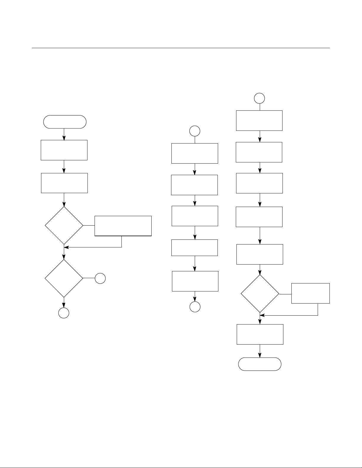
Figure 2-1 details the full procedure for installing a new 3095FB.
PROCEDURES
Figure 2-1. Rosemount 3095FB Installation Flowchart
START
Unpack the
Rosemount
3095FB
Review the
3095FB Product
Manual
Hazardous
Location
?
No
Yes
Review Appendix B
A
BENCH
CONFIGURE
Connect Bench
Power Supply
Connect Personal
Computer
Perform Bench
Configuration
Tasks
B
FIELD
INSTALLATION
Review Installation
Considerations
Mount
Transmitter and
Install Bolts
(Optional) Install
RTD Assembly
Make Field Wiring
Connections
Bench
Configure
?
No
B
Yes
A
(Optl.) Perform
Bench Calibration
Tasks
B
Bench
Configuration
Performed
?
Yes
(Optl.) Perform
Field Calibration
Tas ks
DONE
No
Perform
Configuration
Tasks
2-3
Page 12

Rosemount 3095FB
Reference Manual
00809-0100-4738, Rev DA
May 2006
Review Installation
Considerations
When choosing an installation location and position, take into account the
need for access to the transmitter. For dimensional drawing information see
page A-6.
Process Flange Orientation
Mount the process flanges with sufficient clearance for process connections.
For safety reasons, place the drain/vent valves so the process fluid is directed
away from you when the vents are used. In addition, consider the possible
need for a testing or calibration input.
Housing Rotation
See “Consider Housing Rotation” on page 2-11.
Terminal Side of Electronics Housing
Mount the transmitter so that the terminal side is accessible. A 0.75-inch (19
mm) clearance is required for cover removal. Use a conduit plug on the
unused side of the conduit opening.
Circuit Side of Electronics Housing
Provide 0.75 inches (19 mm) clearance if possible for cover removal. Three
inches of clearance is required for cover removal if a display is installed.
Cover Installation
Always install the electronics housing covers metal-to-metal to ensure a
proper seal.
2-4
Page 13
Reference Manual
00809-0100-4738, Rev DA
Rosemount 3095FB
May 2006
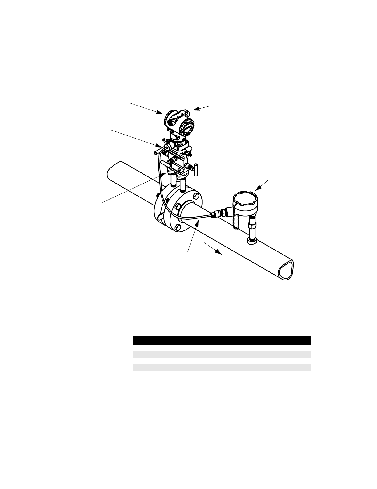
Mount the Transmitter Figure 2-2 illustrates a typical 3095 installation site. Major components of the
installation are identified in these figures.
Figure 2-2. Typical Rosemount 3095FB Installation Site
3095FB
RTD Connector
Process
Connections
Conduit Opening
for Connections
to RTU and
Power Supply
RTD Assembly
Table 2-1. Transmitter Weight
RTD Cable
Flow
3095-3095f22a
The 3095FB transmitter total weight varies depending on the components
ordered (see Table 2-1). This weight must be securely supported.
Component Weight
3095FB Without Options 6 lb (2,7 kg)
LCD Meter for Aluminum Housing 0.5 lb (0,2 kg)
SST Mounting Bracket for Coplanar Flange 1.0 lb (0,5 kg)
12 ft (3,66 m) cable 0.5 lb (0,2 kg)
24 ft (7,32 m) cable 2.2 lb (1,0 kg)
Mounting Brackets
Optional mounting brackets available with the 3095FB facilitate mounting to a
panel, wall, or 2-inch pipe. The bracket option for use with the Coplanar flange
is 316 SST with 316 SST bolts. Figure 2-3 shows bracket dimensions and
mounting configurations for this option. When installing the transmitter to one
of the mounting brackets, torque the bolts to 125 in-lb.
2-5
Page 14
Rosemount 3095FB
Reference Manual
00809-0100-4738, Rev DA
May 2006
NOTE
Most transmitters are calibrated in the horizontal position. Mounting the
transmitter in any other position will shift the zero point to the equivalent
amount of liquid head caused by the varied mounting position. To reset zero
point, refer to “Sensor Trim” on page 4-16.
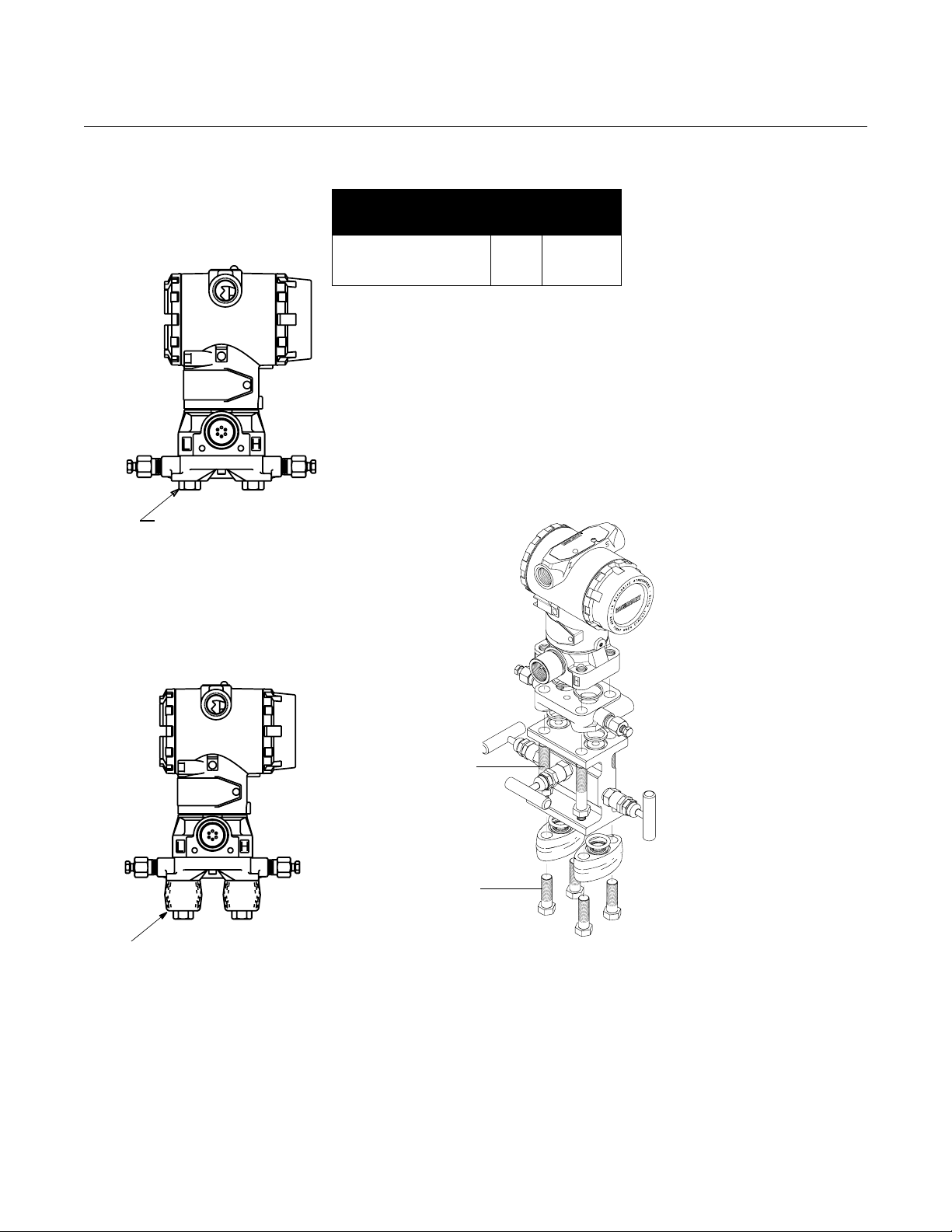
Mounting Bolts
The following guidelines have been established to ensure a tight flange,
adapter, or manifold seal. Use only bolts supplied with the transmitter or sold
by Rosemount Inc. as a spare part to the Rosemount 3095FB transmitter.
The Rosemount 3095FB is shipped with the Coplanar flange installed with
four 1.75-inch flange bolts. The following bolts also are supplied to facilitate
other mounting configurations:
• Four 2.25-inch manifold/flange bolts for mounting the Coplanar flange
on a three-valve manifold. In this configuration, the 1.75-inch bolts may
be used to mount the flange adapters to the process connection side of
the manifold.
• (Optional) If flange adapters are ordered, four 2.88-inch flange/adapter
bolts for mounting the flange adapters to the Coplanar flange.
Figure 2-3 shows the optional mounting bracket and mounting configurations.
Stainless steel bolts supplied by Rosemount Inc. are coated with a lubricant to
ease installation. Carbon steel bolts do not require lubrication. No additional
lubricant should be applied when installing either type of bolt. Bolts supplied
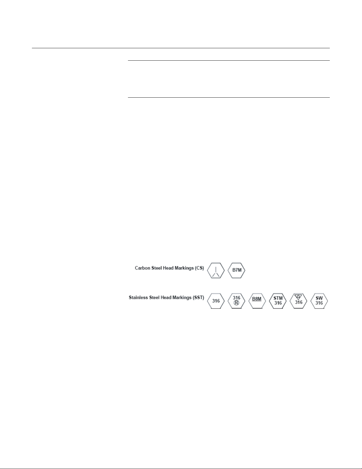
by Rosemount Inc. are identified by their head markings:
2-6
Page 15
Rosemount 3095FB
Figure 2-3. Optional Mounting Brackets and Mounting Configurations
Description Qty.
Flange bolts
Flange/adapter bolts
Manifold/flange bolts
4
4
4
Reference Manual
00809-0100-4738, Rev DA
May 2006
Size
in. (mm)
1.75 (44)
2.88 (73)
2.25 (57)
1.75 (44) x 4
TRANSMITTER WITH
FLANGE BOLTS
2.88 (73) x 4
TRANSMITTER WITH
OPTIONAL FLANGE ADAPTERS
AND FLANGE/ADAPTER BOLTS
2.25 (57) x 4
1.75 (44) x 4
3095-3095D05M, 3095C05A, fieldbus\3095\3095a29A
TRANSMITTER WITH 3-VALVE MANIFOLD
MANIFOLD/FLANGE BOLTS
FLANGE ADAPTERS
AND FLANGE/ADAPTER BOLTS
NOTE
Dimensions are in inches (millimeters)
2-7
Page 16

Rosemount 3095FB
Reference Manual
00809-0100-4738, Rev DA
May 2006
Mounting Requirements
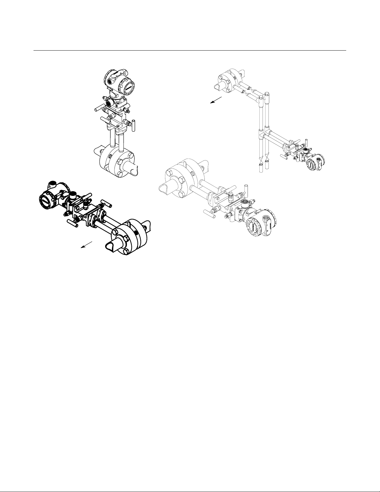
Refer to figure 2-4 for examples of the following mounting considerations:
Liquid Flow Measurement
• Place taps to the side of the line to prevent sediment deposits on the
transmitter’s process isolators.
• Mount the transmitter beside or below the taps so gases can vent into
the process line.
• Mount drain/vent valve upward to allow gases to vent.
Gas Flow Measurement
• Place taps in the top or side of the line.
• Mount the transmitter beside or above the taps so liquid will drain into
the process line.
Steam Flow Measurement
• Place taps to the side of the line.
• Mount the transmitter below the taps to ensure that the impulse piping
will stay filled with condensate.
• Fill impulse lines with water to prevent the steam from contacting the
transmitter directly and to ensure accurate measurement start-up.
NOTE
In steam or other elevated temperature services, it is important that
temperatures at the coplanar process flanges not exceed 250 °F (121 °C) for
transmitters with silicone fill or 185 °F (85 °C) for inert fill.
2-8
Page 17
Rosemount 3095FB
Figure 2-4. Example Installations
Flow
GAS SERVICE
Reference Manual
00809-0100-4738, Rev DA
May 2006
STEAM
SERVICE
Flow
LIQUID SERVICE
Flow
Process Connections The 3095 process connections on the transmitter flange are 1/4–18 NPT.
Flange adapter unions with 1/2–14 NPT connections are available as options.
These are Class 2 threads; use your plant-approved lubricant or sealant when
making the process connections. The process connections on the transmitter
flange are on 2
five-valve manifold. By rotating one or both of the flange adapters, connection
centers of 2, 2
Install and tighten all four flange bolts before applying pressure or process
leakage will result. When properly installed, the flange bolts will protrude
through the top of the module housing. Do not attempt to loosen or remove
the flange bolts while the transmitter is in service.
1
/8-inch (54-mm) centers to allow direct mounting to a three- or
1
/8, or 21/4 inches (51, 54, or 57 mm) may be obtained.
3095\3095b03b, 3095d03b
2-9
Page 18
Rosemount 3095FB
Reference Manual
00809-0100-4738, Rev DA
May 2006
To install adapters to a Coplanar flange, perform the following procedure:
1. Remove the flange bolts.
2. Leaving the flange in place, move the adapters into position with the
O-ring installed.
3. Clamp the adapters and the Coplanar flange to the transmitter
module using the larger of the bolts supplied.
4. Tighten the bolts. Refer to “Mounting Bolts” on page 2-6 for torque
specifications.
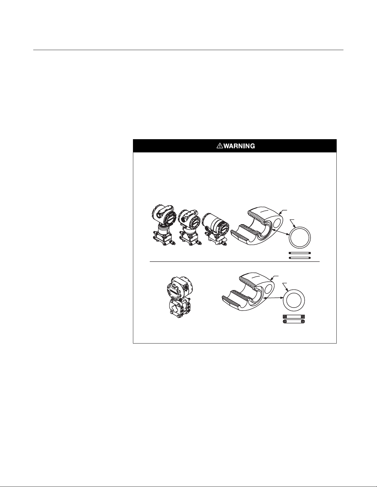
Failure to install proper flange adapter O-rings can cause process leaks, which can
result in death or serious injury.
The two flange adapters are distinguished by unique O-ring grooves. Only use the
O-ring that is designed for its specific flange adapter, as shown below.
ROSEMOUNT 3051S/ 3051/3001/3095/2024
Flange Adapter
O-ring
3051S 3051C 2024
ROSEMOUNT 1151
Refer to the Spare Parts list on page A-9 for the correct part numbers of the flange
adapters and O-rings designed for Rosemount 3051 transmitters.
Teflon Based
Elastomer
Flange Adapter
O-ring
3051-0569A01A
Teflon
Elastomer
When compressed, Teflon® O-rings tend to cold flow, which aids in their
sealing capabilities. Whenever you remove flanges or adapters, visually
inspect the Teflon O-rings. Replace them if there are any signs of damage,
such as nicks or cuts. If they are undamaged, you may reuse them. If you
replace the O-rings, retorque the flange bolts after installation to compensate
for cold flow.
2-10
Impulse Piping
The piping between the process and the transmitter must accurately transfer
the pressure to obtain accurate measurements. There are five possible
sources of error: pressure transfer, leaks, friction loss (particularly if purging is
used), trapped gas in a liquid line, liquid in a gas line, and density variations
between the legs.
Page 19

Rosemount 3095FB
Reference Manual
00809-0100-4738, Rev DA
May 2006
The best location for the transmitter in relation to the process pipe depends on
the process itself. Use the following guidelines to determine transmitter
location and placement of impulse piping:
• Keep impulse piping as short as possible.
• For liquid service, slope the impulse piping at least 1 inch per foot (8
cm per m) upward from the transmitter toward the process connection.
• For gas service, slope the impulse piping at least 1 inch per foot (8 cm
per m) downward from the transmitter toward the process connection.
• Avoid high points in liquid lines and low points in gas lines.
• Make sure both impulse legs are the same temperature.
• Use impulse piping large enough to avoid friction effects and blockage.
• Vent all gas from liquid piping legs.
• When using a sealing fluid, fill both piping legs to the same level.
• When purging, make the purge connection close to the process taps
and purge through equal lengths of the same size pipe. Avoid purging
through the transmitter.
• Keep corrosive or hot (above 250 °F [121 °C]) process material out of
direct contact with the sensor module and flanges.
• Prevent sediment deposits in the impulse piping.
• Keep the liquid head balanced on both legs of the impulse piping.
• Avoid conditions that might allow process fluid to freeze within the
process flange.
Consider Housing
Rotation
The electronics housing can be rotated up to 180 degrees (left or right) to
improve field access or to better view the optional LCD display. To rotate the
housing, perform the following procedure:
1. Loosen the housing rotation set screw using a 5/64-in. hex wrench.
2. Turn the housing up to 180 degrees to the left or right of its original
3. Retighten the housing rotation set screw.
Set Jumpers Security
You can prevent changes to the transmitter configuration data with the write
protection jumper. Security is controlled by the security (write protect) jumper
located on the electronics board or display face. Position the jumper on the
transmitter circuit board in the “ON” position to prevent accidental or
deliberate change of configuration data.
If the transmitter write protection jumper is in the “ON” position, the transmitter
will not accept any “writes” to its memory. Configuration changes, such as
digital trim and reranging, cannot take place when the transmitter security is
on.
AC Termination (AC)
(as shipped) position. Do not rotate the housing more than 180
degrees without first performing a disassembly procedure (see
“Disassembly Procedures” on page 5-5). Over-rotation will sever the
electrical connection between the sensor module and the electronics
module.
2-11
The RS-485 bus needs to be terminated once at both ends, and should not be
terminated elsewhere on the bus. Setting the AC TERMINATION (AC) switch
to ON provides AC bus termination.
Page 20

Rosemount 3095FB
Reference Manual
00809-0100-4738, Rev DA
May 2006
NOTE
The RTU may already provide one RS-485 bus termination.
Pull-down (B) and Pull-up (A)
These switches are used to put the RS-485 bus into the idle state. Set these
switches either to both ON (idle state), or to both OFF (lets the bus float). If a
transmitter has multiple communication errors, set these switches to ON (idle
state).
NOTE
Only one device on an RS-485 bus should set the bus to the idle state. In
some installations, the RTU might maintain the bus in the idle state when the
RS-485 bus is inactive.
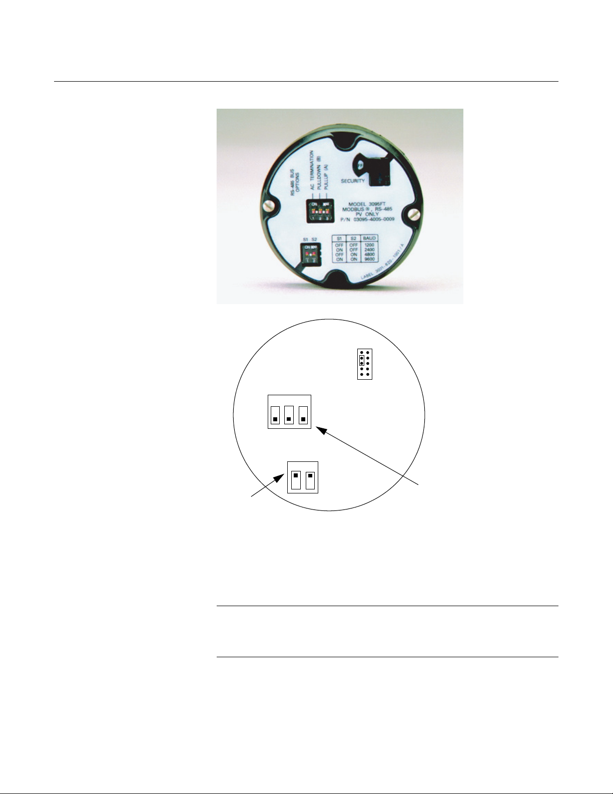
Baud Rate (S1 and S2)
Table 2-2 identifies four available baud rates for RS-485 Modbus
communications.
Table 2-2. Baud Rate Settings
S1 S2 Baud Rate
OFF OFF 1200
ON OFF 2400
OFF ON 4800
ON ON 9600
Configuring RS485 and Security Jumpers
When shipped from the factory, the RS-485 switches are all set to off, and the
baud rate switches are set to 9600 (see Table 2-2).
To reposition the jumpers, follow the procedure described below.
1. If the transmitter is installed, remove power.
2. Remove the housing cover opposite the field terminal side. Do not
remove the transmitter covers in explosive atmospheres when the
circuit is live.
3. Remove the LCD meter if present.
4. Locate the switches on the output electronics board (see Figure 2-5),
and then move the switch to the desired setting.
5. Reattach the transmitter cover. Transmitter covers must be fully
engaged to meet Explosion-Proof requirements.
2-12
Page 21
Rosemount 3095FB
Figure 2-5. Output Board Switches
Reference Manual
00809-0100-4738, Rev DA
May 2006
OFF
ON
OFF
ON
<
<
Real-Time
Clock
Battery
Jumper
>
>
ON
OFF
RS-485
Configuration
SECURITY
AC (B ) (A)
ON
OFF
S1 S2
Baud
Rate
OUTPUT ELECTRONICS BOARD
RTD Assembly (Optional) The Rosemount 3095FB MultiVariable Transmitter is compatible with the
Series 68 or Series 78 RTD Assembly.
NOTE
To meet ISSep/CENELEC Flameproof certification, only European
Flameproof Cable Assemblies (Process Temperature Input Codes A, B, or C)
may be used for RTD cable installation.
3095-065AB
2-13
RTD Installation Procedure
All RTD Cable Assemblies use the 3095 RTD Cable Connector.
Page 22
Rosemount 3095FB
Identify the type of cable being used, and follow the installation steps specific
to the type of cable.
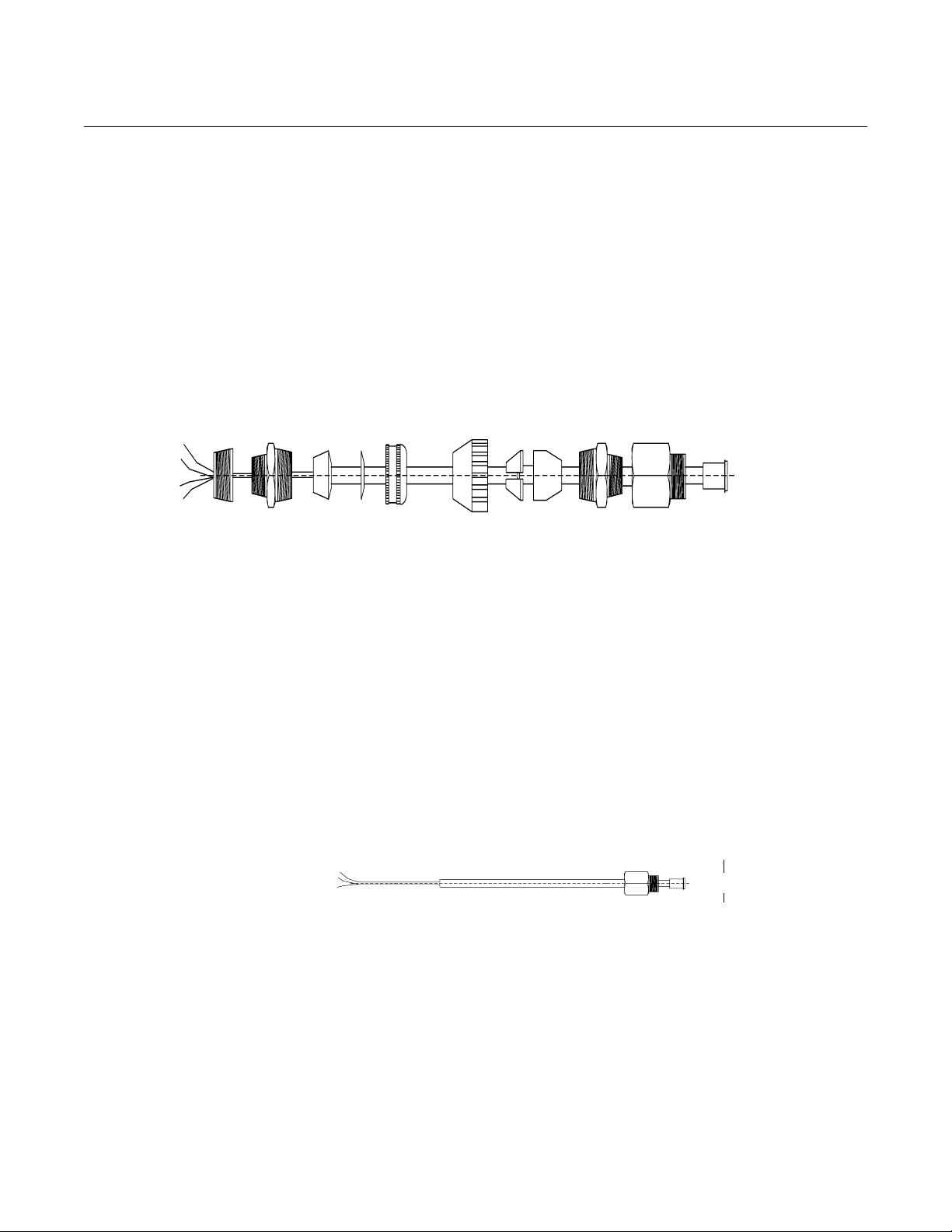
Installing an Armored Shielded RTD Cable
Figure 2-6 details a standard armored shielded RTD cable.
Figure 2-6. Armored Shielded RTD Cable
Washer
Rubber Bushing
(Slide stop to edge
00809-0100-4738, Rev DA
• Armored Shielded RTD Cable
• Shielded RTD Cable (intended for conduit use)
• CENELEC Flameproof RTD Cable
Compression
Cap
Fitting
Reference Manual
May 2006
Connect to
transmitter
3
/4 to 1/2–in. NPT
Adapter
(Screws into RTD
Connection Head)
Compression Fitting
Figure 2-7. Shielded RTD Cable
Cap
Brushing
1. Fully engage the black cable connector to the 3095 RTD connector
(figure 2-9).
2. Tighten the cable adapter until metal contacts metal (figure 2-10).
3. Install the compression fitting
4. Use pliers to tighten the cap onto the compression fitting (figure 2-11).
Installing a Shielded RTD Cable (intended for conduit use)
Figure 2-7 details a standard shielded RTD cable.
Cable Adapter 1/2–14 NPT
Black Cable Connector
1. Fully engage the black cable connector to the 3095 RTD connector
(figure 2-9).
2. Tighten the cable adapter until metal contacts metal (figure 2-10).
3095-0020D01A
2-14
Installing a CENELEC Flameproof RTD Cable
Figure 2-8 details a CENELEC flameproof RTD cable.
Page 23
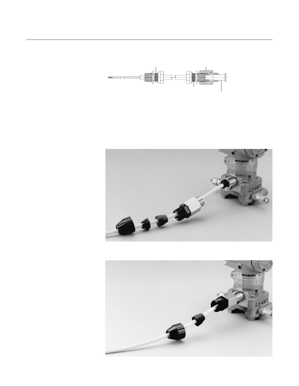
Rosemount 3095FB
Figure 2-8. CENELEC Flameproof RTD Cable
Reference Manual
00809-0100-4738, Rev DA
May 2006
1. Fully engage the black cable connector to the 3095 RTD connector
(figure 2-9).
2. Tighten the cable adapter and cable gland until metal contacts metal
(figure 2-10).
Figure 2-9. Engaging the Black Cable Connector
RTD Cable Gland CM20
Cable Adapter
Cable Gland
Black Cable Connector
FIGURE 2-10. Tightening the Cable Adapter
2-15
Page 24
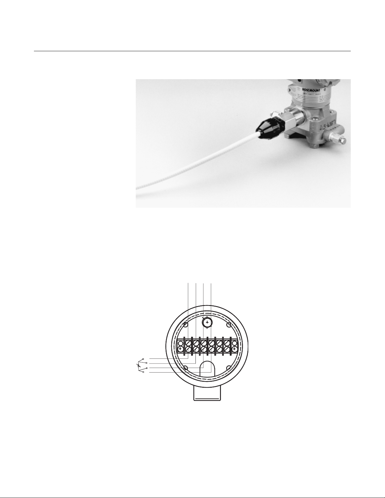
Rosemount 3095FB
Figure 2-11. Tightening the Cap
Reference Manual
00809-0100-4738, Rev DA
May 2006
Connecting the RTD to the Assembly
Make all necessary wiring connections inside the RTD Flat Connection Head
as explained in the sensor wiring instructions included with the RTD.
Figure 2-12 illustrates a typical wiring configuration of the Rosemount RTD
cable assembly with a 4-wire RTD.
Figure 2-12. RTD Sensor Wiring Diagram
RTD Cable Assembly Wires
White
White
Red
Red
A
A
B
B
3095\3095_23A.eps
Connect Wiring and
Power Up
2-16
The transmitter terminal block is in the compartment of the electronics
housing labeled “FIELD TERMINALS.” The other compartment contains the
transmitter electronics module.
Refer to figure 2-13 to assist in wiring connections.
Page 25

Rosemount 3095FB
Reference Manual
00809-0100-4738, Rev DA
May 2006
For explosion-proof installations, wiring connections must be made per Appendix B.
For ALL installations, wiring connections must be made in accordance with local or
national installation codes such as the NEC NFPA 70.
NOTES
• Do not run field wiring in conduit or open trays with other
non-transmitter power wiring, or near heavy electrical equipment.
• Shielded wiring is not required, but twisted pairs should be used for
best results. Twisted pair is required for RS-485 bus wiring.
• Runs under 1000 feet should be AWG 22 or larger. Runs from 1000 to
4000 feet should be AWG 20 or larger.
• Wiring should not exceed AWG 16.
• For connections in ambient temperatures above 140 °F (60 °C), use
wiring rated for at least 194 °F (90 °C).
• All connections should be made before applying power to the device.
Incorrect field wiring connections may damage the Rosemount 3095FB. Do not connect
power wiring to the RS-485 terminals.
To make connections, perform the following procedure:
1. Remove the housing cover on the side marked “FIELD TERMINALS.”
Do not remove the cover in explosive atmospheres when the circuit is
live. All power to the transmitter is supplied over the signal wiring.
2. Connect the lead that originates at the positive side of the power
supply to the terminal marked “+” and the lead that originates from the
negative side of the power supply to the terminal marked “–”. Avoid
contact with the leads and terminals.
3. Connect the lead that originates from the “A” line from the RS-485
bus to the terminal marked “A” and the lead that originates from the
“B” line to the terminal marked “B.”
4. Plug and seal unused conduit connections on the transmitter housing
to avoid moisture accumulation in the terminal side of the housing. If
you do not seal the unused connections, mount the transmitter with
the electrical housing positioned downward for drainage. Install wiring
with a drip loop. Arrange the drip loop so the bottom is lower than the
conduit connections and the transmitter housing.
5. Attach and tighten all housing covers. Transmitter covers must be
fully engaged to meet Explosion-Proof requirements and to achieve
the proper environmental seal.
2-17
Page 26
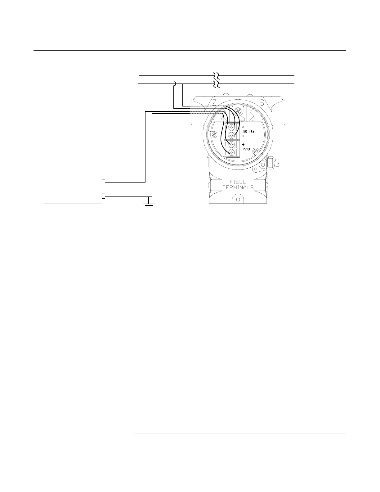
Rosemount 3095FB
Figure 2-13. Field Wiring Connections
RS-485 Bus
+
User-Provided
Power Supply
-
Reference Manual
00809-0100-4738, Rev DA
May 2006
A
B
Inductive-based transient protectors, including the Rosemount 470, can
adversely affect the output of the 3095FB transmitter. Do not use the
Rosemount 470 for transient protection with the 3095FB. If your application
requires transient protection, install the Transient Protection Terminal Block
(Section 5: Troubleshooting).
Signal Wiring Grounding
Do not run signal wiring in conduit or open trays with power wiring, or near
heavy electrical equipment. You may ground the signal wiring at any one point
on the signal loop, or leave it ungrounded. The negative terminal of the power
supply is a recommended grounding point. Device must be properly grounded
or earthed according to local electric codes.
Power Supply
The transmitter requires between 7.5 and 30 V dc to operate and provide
complete functionality. The dc power supply should provide power with less
than 2% ripple.
RS-485 Bus
• The 3095FB does not provide electrical isolation between the RS-485
bus and the transmitter power supply.
• Maintain a bus topology and minimize stub length.
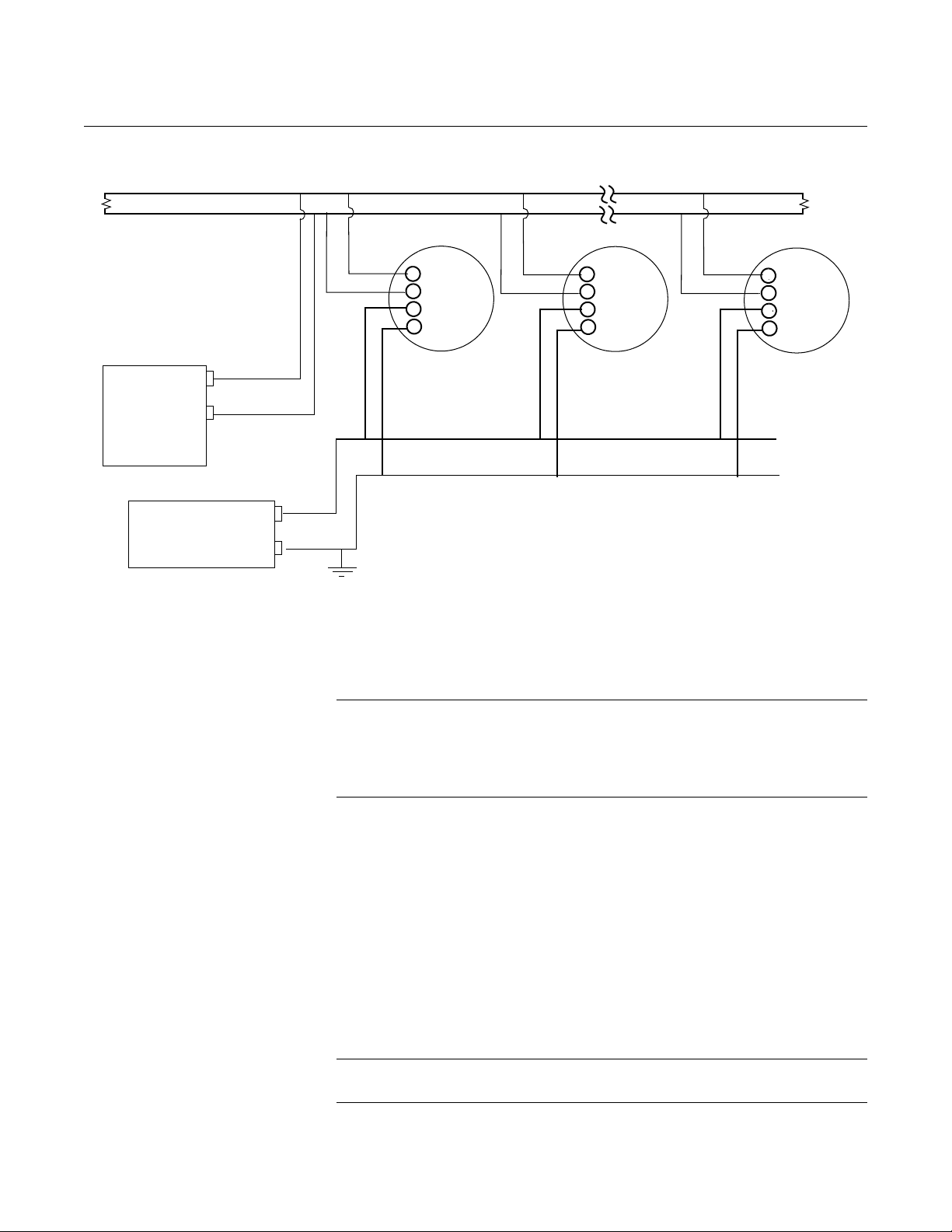
• Figure 2-14 identifies multidrop wiring topology. Up to 32 devices may
be wired on one RS-485 bus.
• The RS-485 bus needs to be terminated once at both ends, and should
not be terminated elsewhere on the bus. Setting the 3095FB AC
termination (AC) switch to ON (see page 2-11) is one method to
provide AC bus termination.
2-18
NOTE
The RTU may already provide one RS-485 bus termination.
Page 27
Rosemount 3095FB
Figure 2-14. RS-485 Multidrop Topology
Twisted pair required
120 ohm
RS-485 Bus
Reference Manual
00809-0100-4738, Rev DA
May 2006
A
B
120
ohm
RTU
User-Provided
Power Supply
HAZARDOUS
LOCATIONS
A
RS-485
B
+
PWR
-
A
B
+
-
Rosemount
3095FB
Twisted pair not required
A
RS-485
B
+
PWR
-
Rosemount
3095FB
. . .
A
RS-485
B
+
PWR
-
Rosemount
3095FB
The Rosemount 3095FB Transmitter has explosion-proof housing and
circuitry. Individual transmitters are clearly marked with a tag indicating the
certifications they carry. See Appendix B for specific approval categories and
installation drawings.
NOTE
Once a device labeled with multiple approvals is installed, it should not be
reinstalled using any other approval type(s). Permanently mark the
certification label to distinguish the installed approval type from unused
approval types.
Grounding the
Transmitter Case
2-19
The transmitter case should always be grounded in accordance with national
and local electrical codes. The most effective transmitter case grounding
method is direct connection to earth ground with minimal impedance.
Methods for grounding the transmitter case include:
• Internal Ground Connection: The Internal Ground Connection screw
is inside the FIELD TERMINALS side of the electronics housing. This
screw is identified by a ground symbol, and is standard on all
Rosemount 3095FB transmitters.
• External Ground Assembly: This assembly is included with the
transient protection terminal block. The External Ground Assembly can
also be ordered as a spare part (03031-0398-0001).
NOTE
Do not ground the RS-485 bus at any point on the bus.
Page 28

Rosemount 3095FB
Reference Manual
00809-0100-4738, Rev DA
May 2006
NOTE
The transient protection terminal block does not provide transient protection
unless the transmitter case is properly grounded. Use the above guidelines to
ground the transmitter case. Do not run the transient protection ground wire
with field wiring as the ground wire may carry excessive current if a lighting
strike occurs. Grounding the transmitter case via threaded conduit connection
may not provide sufficient ground.
ROSEMOUNT 305
INTEGRAL MANIFOLD
Integral Manifold
Installation Procedure
The Rosemount 3095FB can be fitted with a 305 Integral Manifold. Supported
manifolds include:
• Traditional Manifold (Rosemount RM style only)
• 3-Valve Coplanar Manifold
• 5-Valve Coplanar Manifold
To install a Rosemount 305 Integral Manifold to a 3095FB transmitter:
1. Inspect the Teflon sensor module O-rings. If the O-rings are
undamaged, reusing them is recommended. If the O-rings are
damaged (if they have nicks or cuts, for example), replace them with
new O-rings.
IMPORTANT
If replacing the O-rings, take care not to scratch or deface the O-ring grooves
or the surface of the isolating diaphragm while you remove the damaged
O-rings.
2. Install the Integral Manifold on the sensor module. Use the four
2.25-in. manifold bolts for alignment. Finger tighten the bolts, then
tighten the bolts incrementally in a cross pattern to final torque value.
See “Mounting Bolts” on page 2-6 for complete bolt installation
information and torque values. When fully tightened, the bolts should
extend through the top of the module housing.
3. If the Teflon O-rings have been replaced, the flange bolts should be
re-tightened after installation to compensate for cold flow of the
O-rings.
2-20
NOTE
Always perform a zero trim on the transmitter/manifold assembly after
installation to eliminate mounting effects.
Page 29
Reference Manual
00809-0100-4738, Rev DA
Rosemount 3095FB
May 2006
Integral Manifold
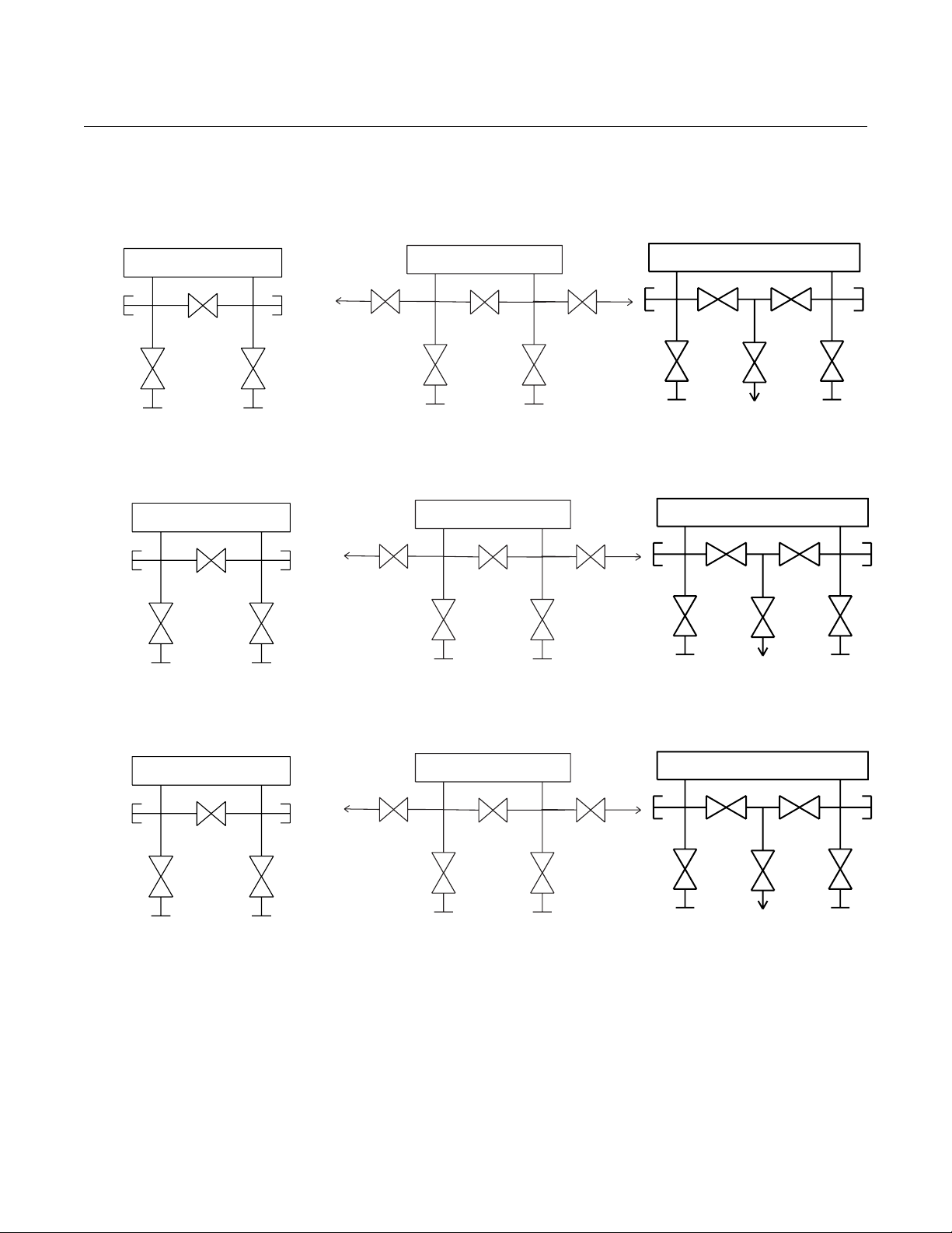
Operation
In normal operation the two block valves between the process and instrument ports will be open and the equalizing
valve(s) will be closed.
L
Test
(Plugged)
Isolate
(open)
Process
Drain/
Vent
Valve
Isolate
(open)
H
Equalize
(closed)
Process
THREE-VALVE
L
Isolate
(open)
Drain/
Vent
Valve
Tes t / Vent
Port
(closed) (closed)
Isolate
(open)
HH
Equalize
(closed)
Process
FIVE-VALVE
L
Tes t / Vent
Isolate
(open)
Port
(Plugged)
Tes t
Isolate
(open)
Process
Equalize
(closed)
Test/ Vent (Closed)
Equalize
(closed)
FIVE-VALVE NAT. GAS
To check zero the 3095FB, close the block valve to the low pressure (downstream side) of the transmitter first.
Tes t / Vent
(closed)
Isolate
(closed)
Port
(Plugged)
Isolate
Tes t
(open)
Process
Equalize
(closed)
Test/ Vent (Closed)
FIVE-VALVE NAT. GAS
Drain/
Vent
Valve
Isolate
(open)
H
Equalize
(closed)
Process
THREE-VALVE
L
Drain/
Vent
Valve
Isolate
(closed)
Test/ Vent
Port
(closed)
Isolate
(open)
HH
Equalize
(closed)
Process
L
FIVE-VALVE
Next, open the center (equalize) valve(s) to equalize the pressure on both sides of the transmitter.
Tes t / Vent
(closed)
Isolate
(closed)
Port
(Plugged)
Isolate
Tes t
(open)
Process
Equalize
(open)
Test/ Vent (Closed)
FIVE-VALVE NAT. GAS
Drain/
Vent
Valve
Isolate
(open)
H
Equalize
(open)
Process
THREE-VALVE
L
Drain/
Vent
Valve
Isolate
(closed)
Test/ Vent
Port
(closed)
Isolate
(open)
HH
Equalize
(open)
Process
L
FIVE-VALVE
Equalize
(closed)
Equalize
(open)
L
Tes t
(Plugged)
Isolate
(closed)
Process
L
Tes t
(Plugged)
Isolate
(closed)
Process
2-21
Page 30
Reference Manual
00809-0100-4738, Rev DA
Rosemount 3095FB
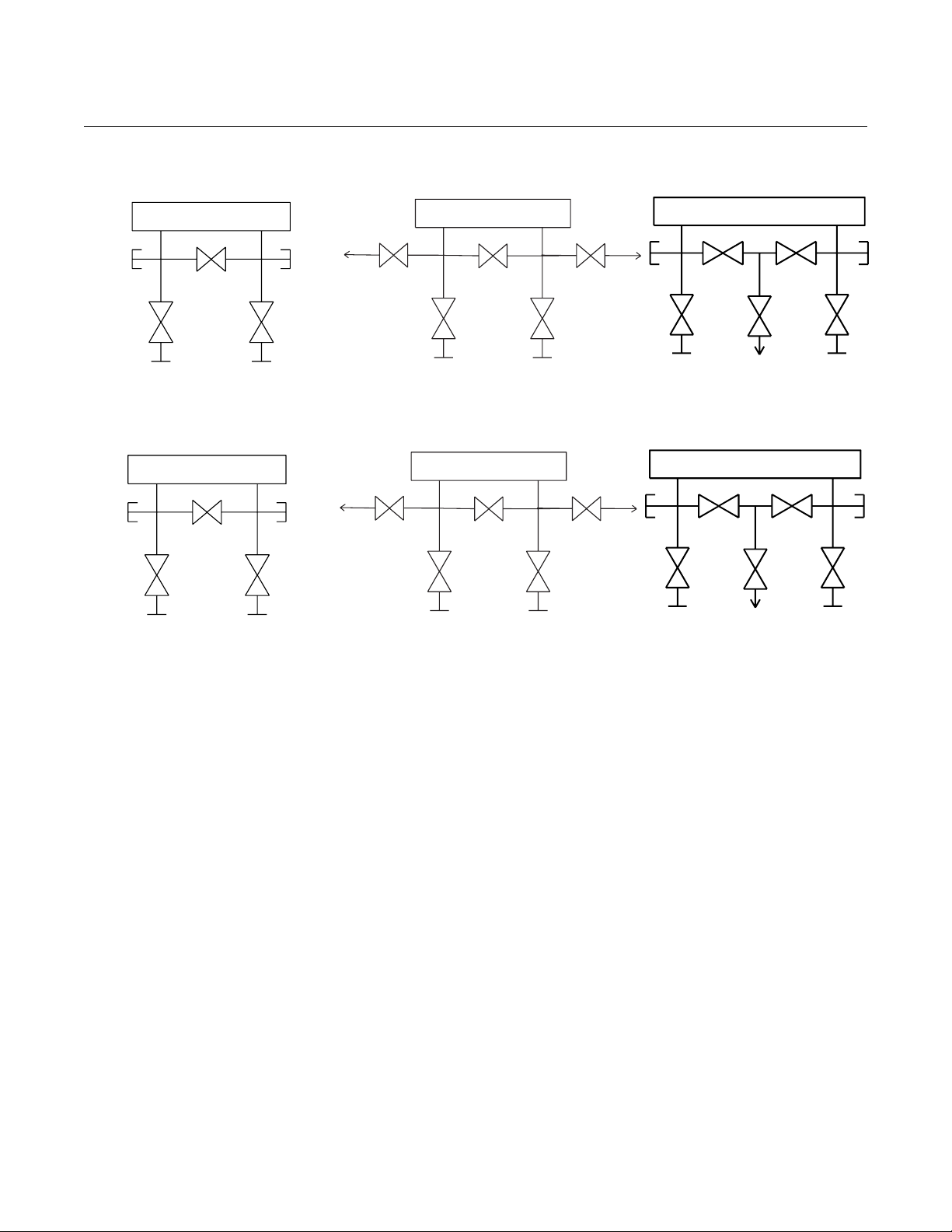
The manifold valves are now in the proper configuration for zeroing the transmitter. To return the transmitter to
service, close the equalizing valve(s) first.
May 2006
Drain/
Vent
Valve
Isolate
(open)
H
Equalize
(closed)
Process
THREE-VALVE
L
Drain/
Vent
Valve
Isolate
(closed)
Test/ Vent
Port
(closed)
HH
Equalize
(closed)
Isolate
(open)
Process
FIVE-VALVE
L
Next, open the block valve on the low pressure side of the transmitter.
Drain/
Vent
Valve
Isolate
(open)
H
Equalize
(closed)
Process
THREE-VALVE
L
Drain/
Vent
Valve
Isolate
(open)
Test/ Vent
Port
(closed)
HH
Equalize
(closed)
Isolate
(open)
Process
FIVE-VALVE
L
(closed)
Isolate
(closed)
(closed)
Isolate
(open)
Tes t/
Vent
(Plugged)
Tes t/
Vent
(Plugged)
Tes t
Isolate
(open)
Process
Tes t
Isolate
(open)
Process
Equalize
(closed)
Test/ Vent (Closed)
Equalize
(closed)
FIVE-VALVE NAT. GAS
Equalize
(closed)
Test/ Vent (Closed)
Equalize
(closed)
Process
FIVE-VALVE NAT. GAS
L
Test
(Plugged)
Isolate
(closed)
Process
L
Test
(Plugged)
Isolate
(open)
2-22
Page 31

Reference Manual
00809-0100-4837, Rev DA
May 2006
Rosemount 3095FB
Section 3 Modbus Communication
Review the Modbus Protocol Guide for the Rosemount 3095FB Multivariable
Transmitter with Modbus Protocol, Revision F in the next few pages.
Use this document to determine which process variables and status bits you
wish to retrieve from the Rosemount 3095FB.
Suggestions and Tips We recommend that you review the Modbus Protocol Guide in the following
manner:
1. Read Sections 1–3 to gain an overview of how the Rosemount
3095FB implements the Modbus RTU protocol.
2. Read Sections 4–9 as needed to determine which Rosemount
3095FB registers will require read/write actions in order to meet your
process control needs.
NOTE
Be sure to consider Section 3: 8.0 in the Modbus Protocol Guide. The only
way to detect transmitter exceptions is by polling the registers described in
this section.
NOTE
Additional registers may be added to the Modbus Protocol Guide with future
software revisions and upgrades.
NOTE
The following functions are only available for Rosemount 3095FB
Transmitters with software revision 107 or greater:
- Configurable Floating Point Format (Section 3: 3.4)
- Scaled Integers (Section 3: 5.3)
- Duplicate Modbus Register Functionality including 32-bit floating
point registers (Section 3: 2.3.1)
www.rosemount.com
Page 32

Rosemount 3095FB Multivariable Transmitter
with Modbus Protocol
Modbus Protocol Guide
Report Number: D9500114
Revision: F
Page 1 of 79
Page 33

Model 3095FB Multivariable Transmitter with Modbus Protocol
Modbus Protocol Guide
TABLE OF CONTENTS
1.0 Introduction . . . . . . . . . . . . . . . . . . . . . . . . . . . . . . . . . . . . . . . . . . . . . . . . . . . . . . . . . . . . .4
1.1 Purpose . . . . . . . . . . . . . . . . . . . . . . . . . . . . . . . . . . . . . . . . . . . . . . . . . . . . . . . . . . . . .4
1.2 References . . . . . . . . . . . . . . . . . . . . . . . . . . . . . . . . . . . . . . . . . . . . . . . . . . . . . . . . . .4
1.3 Abbreviations, Definitions, and Acronyms . . . . . . . . . . . . . . . . . . . . . . . . . . . . . . . . .4
2.0 Overview of Modbus Conventions . . . . . . . . . . . . . . . . . . . . . . . . . . . . . . . . . . . . . . . . . .6
2.1 Physical Communications Layer . . . . . . . . . . . . . . . . . . . . . . . . . . . . . . . . . . . . . . . . .6
2.2 Transactions on Modbus Networks . . . . . . . . . . . . . . . . . . . . . . . . . . . . . . . . . . . . . . .6
2.2.1 Address Field . . . . . . . . . . . . . . . . . . . . . . . . . . . . . . . . . . . . . . . . . . . . . . . . . .6
2.2.2 Function Field . . . . . . . . . . . . . . . . . . . . . . . . . . . . . . . . . . . . . . . . . . . . . . . . . .6
2.2.3 Data Field . . . . . . . . . . . . . . . . . . . . . . . . . . . . . . . . . . . . . . . . . . . . . . . . . . . . .7
2.2.4 Error Check Field . . . . . . . . . . . . . . . . . . . . . . . . . . . . . . . . . . . . . . . . . . . . . . .7
2.2.5 Broadcast mode and address 0 . . . . . . . . . . . . . . . . . . . . . . . . . . . . . . . . . . . . .7
2.3 Data Types . . . . . . . . . . . . . . . . . . . . . . . . . . . . . . . . . . . . . . . . . . . . . . . . . . . . . . . . . .8
2.3.1 Register Map (available for 3095FB output board Rev. 107 or later) . . . . . .10
2.3.1.1 Accessing Floating Point Registers . . . . . . . . . . . . . . . . . . . . . . . . . .10
2.3.1.2 Accessing Integer Registers . . . . . . . . . . . . . . . . . . . . . . . . . . . . . . . .10
2.3.2 Boolean Map (available for 3095FB output board Rev. 107 or later) . . . . . .12
2.3.2.1 Accessing Boolean Data . . . . . . . . . . . . . . . . . . . . . . . . . . . . . . . . . .12
2.4 Modbus Function Codes . . . . . . . . . . . . . . . . . . . . . . . . . . . . . . . . . . . . . . . . . . . . . . .13
2.5 Exception Responses . . . . . . . . . . . . . . . . . . . . . . . . . . . . . . . . . . . . . . . . . . . . . . . . .15
2.6 Examples of Modbus Commands . . . . . . . . . . . . . . . . . . . . . . . . . . . . . . . . . . . . . . . .16
2.6.1 Reading and Writing Floating Point Data . . . . . . . . . . . . . . . . . . . . . . . . . . . .16
2.6.2 Reading and Writing 16 Bit Registers . . . . . . . . . . . . . . . . . . . . . . . . . . . . . .19
2.6.3 Reading and Writing Bit Registers . . . . . . . . . . . . . . . . . . . . . . . . . . . . . . . . .19
3.0 Communications . . . . . . . . . . . . . . . . . . . . . . . . . . . . . . . . . . . . . . . . . . . . . . . . . . . . . . . .21
3.1 Communication Options . . . . . . . . . . . . . . . . . . . . . . . . . . . . . . . . . . . . . . . . . . . . . . .21
3.2 Communication Statistics . . . . . . . . . . . . . . . . . . . . . . . . . . . . . . . . . . . . . . . . . . . . . .22
3.3 Write Protect Jumper . . . . . . . . . . . . . . . . . . . . . . . . . . . . . . . . . . . . . . . . . . . . . . . . .22
3.4 Floating Point Formats (available for 3095FB output board Rev. 107 or later) . . . .23
4.0 Sensor and Transmitter Information . . . . . . . . . . . . . . . . . . . . . . . . . . . . . . . . . . . . . . .25
4.1 Overview of Sensor and Transmitter Information . . . . . . . . . . . . . . . . . . . . . . . . . . .25
4.2 Transmitter Info . . . . . . . . . . . . . . . . . . . . . . . . . . . . . . . . . . . . . . . . . . . . . . . . . . . . .26
4.3 Identify Transmitter . . . . . . . . . . . . . . . . . . . . . . . . . . . . . . . . . . . . . . . . . . . . . . . . . .30
5.0 Process Variables . . . . . . . . . . . . . . . . . . . . . . . . . . . . . . . . . . . . . . . . . . . . . . . . . . . . . . .31
5.1 Process Variables and Process Variable Unit Codes . . . . . . . . . . . . . . . . . . . . . . . . .31
5.2 Process Variable Limit Checking . . . . . . . . . . . . . . . . . . . . . . . . . . . . . . . . . . . . . . . .32
5.3 Integer Scaling of Process Variables (available for 3095FB output board Rev. 107 or lat-
er) . . . . . . . . . . . . . . . . . . . . . . . . . . . . . . . . . . . . . . . . . . . . . . . . . . . . . . . . . . . . . . .34
5.3.1 Defining Scaled Integers . . . . . . . . . . . . . . . . . . . . . . . . . . . . . . . . . . . . . . . . .35
5.3.1.1 Method 1: Define the Endpoints . . . . . . . . . . . . . . . . . . . . . . . . . . . .36
5.3.1.2 Method 2: Define Scale and Offset . . . . . . . . . . . . . . . . . . . . . . . . . .38
5.3.2 Scaled Integer Error Conditions . . . . . . . . . . . . . . . . . . . . . . . . . . . . . . . . . . .41
5.3.2.1 General Exceptions that Apply to All Scaled Outputs . . . . . . . . . . .41
5.3.2.2 Exceptions that Apply to DP . . . . . . . . . . . . . . . . . . . . . . . . . . . . . . .41
Page 2 of 79
Page 34

Model 3095FB Multivariable Transmitter with Modbus Protocol
Modbus Protocol Guide
5.3.2.3 Exceptions that Apply to SP . . . . . . . . . . . . . . . . . . . . . . . . . . . . . . .42
5.3.2.4 Exceptions that Apply to PT . . . . . . . . . . . . . . . . . . . . . . . . . . . . . . .42
5.4 Untrimmed and Corrected Process Variables . . . . . . . . . . . . . . . . . . . . . . . . . . . . . . .42
5.5 Process Variable Default Values (PT) . . . . . . . . . . . . . . . . . . . . . . . . . . . . . . . . . . . .43
6.0 Calibration . . . . . . . . . . . . . . . . . . . . . . . . . . . . . . . . . . . . . . . . . . . . . . . . . . . . . . . . . . . . .45
6.1 Calibration . . . . . . . . . . . . . . . . . . . . . . . . . . . . . . . . . . . . . . . . . . . . . . . . . . . . . . . . .45
6.1.1 Calibration Flag . . . . . . . . . . . . . . . . . . . . . . . . . . . . . . . . . . . . . . . . . . . . . . . .46
6.2 Damping . . . . . . . . . . . . . . . . . . . . . . . . . . . . . . . . . . . . . . . . . . . . . . . . . . . . . . . . . . .47
6.3 Restore Factory Trim Defaults . . . . . . . . . . . . . . . . . . . . . . . . . . . . . . . . . . . . . . . . . .48
7.0 LCD Display Configuration . . . . . . . . . . . . . . . . . . . . . . . . . . . . . . . . . . . . . . . . . . . . . . .49
8.0 Exception Handling . . . . . . . . . . . . . . . . . . . . . . . . . . . . . . . . . . . . . . . . . . . . . . . . . . . . .50
8.1 Diagnostic Status Bits . . . . . . . . . . . . . . . . . . . . . . . . . . . . . . . . . . . . . . . . . . . . . . . . .50
8.1.1 Critical Alarm . . . . . . . . . . . . . . . . . . . . . . . . . . . . . . . . . . . . . . . . . . . . . . . . .52
8.1.2 Warning . . . . . . . . . . . . . . . . . . . . . . . . . . . . . . . . . . . . . . . . . . . . . . . . . . . . . .52
9.0 Diagnostics . . . . . . . . . . . . . . . . . . . . . . . . . . . . . . . . . . . . . . . . . . . . . . . . . . . . . . . . . . . . .53
9.1 Self Test . . . . . . . . . . . . . . . . . . . . . . . . . . . . . . . . . . . . . . . . . . . . . . . . . . . . . . . . . . .53
9.2 Master Reset . . . . . . . . . . . . . . . . . . . . . . . . . . . . . . . . . . . . . . . . . . . . . . . . . . . . . . . .54
9.3 Restoring Nonvolatile Database to Factory Defaults . . . . . . . . . . . . . . . . . . . . . . . . .54
Appendix A: Modbus Mapping Assignments by Data Types . . . . . . . . . . . . . . . . . . . . . . . .57
Appendix B: Modbus Mapping Assignments by Register . . . . . . . . . . . . . . . . . . . . . . . . . .67
Appendix C: Modbus Mapping of 32-bit Floating Point Registers . . . . . . . . . . . . . . . . . . .76
Appendix D: Scaled Integer Examples . . . . . . . . . . . . . . . . . . . . . . . . . . . . . . . . . . . . . . . . .78
Page 3 of 79
Page 35

Model 3095FB Multivariable Transmitter with Modbus Protocol
Modbus Protocol Guide
1.0 Introduction
The readers of this document are expected to have a general understanding of the Modbus protocol. If you do not have the required knowledge of the Modbus protocol, the Modbus documents
referenced in Section 1.2, on page 4 of this document should be of help. Also Section 2.0, on
page 6 of this document contains a brief overview of the Modbus protocol.
1.1 Purpose
The purpose of this document is to provide the information required to implement within a
host, an effective exchange of data with the Rosemount 3095FB Multivariable Transmitter
with Modbus Protocol. This document defines the Modbus interface and register layout in sufficient detail for the 3095FB.
1.2 References
Modicon Modbus Protocol Reference Guide
1.3 Abbreviations, Definitions, and Acronyms
Table 1-1 Glossary
Term Description
AP absolute pressure - above absolute zero pressure
C degrees Celsius (5 / 9) * (T(F) - 32)
coil A read/write bit register
Conventional Symbol A symbol which is commonly used in the gas industry in equa-
tions or algorithms or other expressions
CRC Cyclic Redundancy Check
default value The initial value set by software. Some of these may be overwrit-
ten by the user via Modbus commands.
discrete input A read only bit register
DP differential pressure
F degrees Fahrenheit (9 / 5) * T(C) + 32
FP IEEE-754 floating point
floating point register Two consecutive 16 bit registers that store an IEEE 754 floating
point number
Page 4 of 79
Page 36

Model 3095FB Multivariable Transmitter with Modbus Protocol
Modbus Protocol Guide
Table 1-1 Glossary
Term Description
FS full scale
GP gage pressure - above atmospheric pressure
holding register A read/write 16 bit register
inH2O inches of water (at defined temperature)
input register A read only 16 bit register
LCD liquid crystal display
psi pounds per square inch
psia pounds per square inch absolute
psig pounds per square inch gauge
PT process temperature
PV(s) process variable(s)
query a request from the master (host) device for a slave device to per-
form an action
register a 16 bit memory location that can be read/write or read only
response a response from a slave device to a master (host) device
SP static pressure
ST sensor temperature
U16 16-bit unsigned integer 0 to 65535
U32 32-bit unsigned integer 0 to 4294967295
U8 8-bit unsigned integer
$ Signifies a hexadecimal number
% Signifies a binary number
Page 5 of 79
Page 37

Model 3095FB Multivariable Transmitter with Modbus Protocol
Modbus Protocol Guide
2.0 Overview of Modbus Conventions
The Rosemount 3095FB is a Modbus compatible measurement device. The transmitter supports
8-bit Remote Terminal Unit (RTU) data transmission mode with a subset of read commands,
write commands, and diagnostic commands used by most Modbus compatible host controllers.
The transmitter’s microprocessor emulates Modbus read/write and read only coils and registers.
2.1 Physical Communications Layer
The communications parameters are set at 8 data bits, 1 stop bit, and no parity. These parameters are not configurable. The baud rate is selectable using dip switches on the 3095FB output
board. Valid baud rates are 1200, 2400, 4800, and 9600.
2.2 Transactions on Modbus Networks
The Modbus protocol uses a master/slave technique, providing for one master and up to 247
slaves. Only the master can initiate a transaction.
Transactions are either a query/response type where only a single slave is addressed, or a
broadcast/no response type where all slaves are addressed.
The host (master) controller can produce query frames or broadcast frames. Query frames
generate a response frame from one slave device. Broadcast frames address all the slave
devices, which do not respond. A query/response message includes one query frame and one
response frame. A broadcast message includes one broadcast frame. Each frame has an
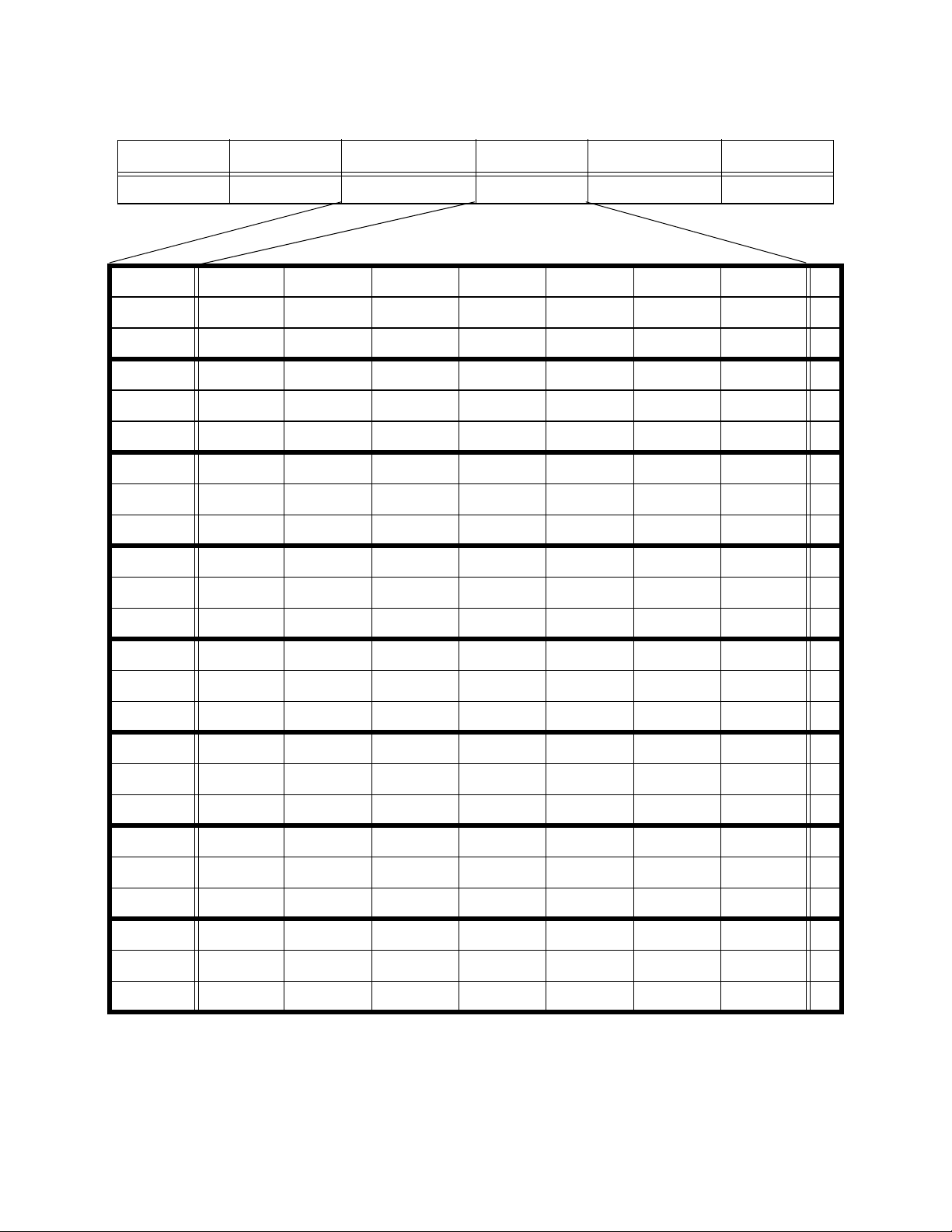
address field, a function field, a data field, and an error check field.
Table 2-1 Format of Query and Response Frame
Address Field(U8) Function Field(U8) Data Field(Size var-
ies with function)
2.2.1 Address Field
In a query frame, the address field contains a slave’s polling address. In a response frame,
the address field contains the polling address of the responding slave device. In a broadcast
frame, the address field contains a 0.
2.2.2 Function Field
Error Check Field(U16)
In a query frame or a broadcast frame, the function field contains a function code, which
indicates the read, write, or diagnostic command to be performed.
Page 6 of 79
Page 38

Model 3095FB Multivariable Transmitter with Modbus Protocol
Modbus Protocol Guide
In a response frame, the function field contains a function code verifying the device’s
response to the command. If the most significant bit in the function field is set, the data field
contains an exception response that explains any errors encountered while processing the
command (see Section 2.5) in the Modbus Protocol Guide.
2.2.3 Data Field
The data field contains information that is specific to each individual function. Section 2.4
gives the data field layout for each function.
2.2.4 Error Check Field
The error check field contains a 16 bit CRC checksum that is used to verify the integrity of
the message frame.
2.2.5 Broadcast mode and address 0
Any query message with a slave address of 0 is a broadcast message. Only Modbus function
codes that write to a register or coil are valid in a broadcast message. Address 0 is reserved
for broadcast messages and therefore is not a valid Modbus slave address.
Page 7 of 79
Page 39

Model 3095FB Multivariable Transmitter with Modbus Protocol
Modbus Protocol Guide
2.3 Data Types
The transmitter’s mapped addresses store and use data types supported by many Modbuscompatible PLCs and host controllers. Table 2-2 lists those data types according to their
mapped addresses and corresponding function codes. To increase compatibility with many
different kinds of hosts, the data types have been remapped to several different locations as
shown in Table 2-2. The additional Modbus addresses were implemented in the 3095FB
output board software beginning with Rev.107.
All the registers in this document are referenced to one. The registers in Modbus messages are
referenced to zero. This means the number of the mapped address register (i.e. 0005) is one
higher than the actual number (i.e. 0004) that is sent in the Modbus frame message.
There are a number of 8 bit values that are stored in 16 bit registers. The 8 bit value is stored in
the Least Significant Byte of the 16 bit register. For example the value $24 would be stored as
$0024. This does not apply to ASCII characters which are stored as two characters in each 16
bit register.
Floating point values are stored as single precision IEEE 754 floating point numbers. Since
IEEE 754 floating point numbers are 32 bits long, they must be stored as either two 16-bit registers or as one 32-bit register. The 3095FB supports both types of floating point registers. See
Section 2.3.1 for a more detailed explanation of the register mapping.
Page 8 of 79
Page 40

Model 3095FB Multivariable Transmitter with Modbus Protocol
Modbus Protocol Guide
Table 2-2 Data Types According to Function Code and Mapped Address
Address
start
register
1 *
1001
10001
401 *
7401
20401
1 *
3001
30001
40001
50001
Address
end
register
86 *
1086
10086
488 *
7444
20488
214 *
3214
30214
40214
50214
Register
size in
bits
1
1
1
16
32
16
16
16
16
16
16
Accessible
via
function
codes
01, 02, 05 Coil Read/
01, 02 Discrete
03, 04,
06**, 16,
69, 70
03, 04 Input reg-
Address
type
input
Floating
point register
isters
Access Description
write
Readonly
Readonly and
read/
write
Readonly
Single ON/OFF bit per coil
(Boolean). Shares the same
register range with the Discrete Inputs. See Section
2.3.2.
Single ON/OFF bit per coil
(Boolean). Shares the same
register range with the Discrete Inputs. See Section
2.3.2.
IEEE 754 floating point
number. Accessed as either
two 16-bit registers or one
32-bit register. See Section
2.3.1.
One 16 bit unsigned integer
per register. Shares the
same register range with
the Holding registers and
ASCII registers. See Sec-
tion 2.3.1.
03, 04, 06, 16Holding
register
03, 04, 06,
16
* Base Address. The other register ranges are duplicate addresses for the base registers. Reading and
writing to these duplicates is the same as reading and writing to the base registers.
** Floating Point numbers can only be written with function code 6 if the register is a 32-bit register.
ASCII
characters
Page 9 of 79
Read/
write
Read/
write
One 16 bit unsigned integer
per register. Shares the
same register range with
the Input registers and
ASCII registers. See Sec-
tion 2.3.1.
Two ASCII characters per
16 bit register. Shares the
same register range with
the Input registers and
Holding registers. See Sec-
tion 2.3.1.
Page 41

Model 3095FB Multivariable Transmitter with Modbus Protocol
Modbus Protocol Guide
2.3.1 Register Map (available for 3095FB output board Rev. 107 or later)
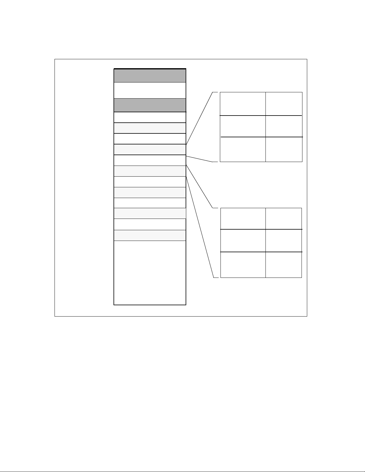
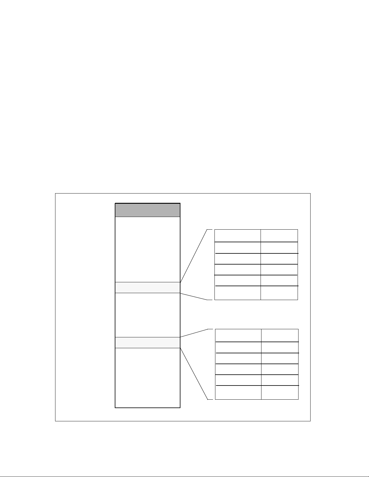
There are two base register blocks used in the register map. These register blocks contain the
integer data and the floating point data. To improve connectivity with many different kinds
of hosts, these base register blocks appear in other address ranges, as shown in Figure 2-1 .
2.3.1.1 Accessing Floating Point Registers
The host can access each floating point register in 3 different locations. To access the 16bit floating point register pairs in the regions other than the base region, simply add the
base register address (i.e. 401) to the desired range (i.e. 20,000), which gives the new register address (i.e. 20,401). The 32-bit floating point numbers do not match up one to one
with the base floating point register pairs, because the 32-bit floating point registers take
half the register space of the 16-bit floating point register pairs. To access the 32-bit floating point registers (7401-7444) use [Equation 1] or see for the complete layout of the 32bit register block.
[Equation 1] 32-bit register address = 7401 + (base address - 401) / 2
Examples:
Differential Pressure = 7401 + (401 - 401) / 2 = 7401
Static Pressure = 7401 + (403 - 401) / 2 = 7402
Differential Pressure Damping = 7401 + (441 - 401) / 2 = 7421
For example, the host can read the floating point value for Differential Pressure(DP) from
3 separate register locations. The DP can be read as 16-bit register pairs by reading registers 401-402 or 20401-20402. The DP can also be read as one 32-bit register at location
7401.
2.3.1.2 Accessing Integer Registers
The integer registers consist of the input registers, holding registers, and ASCII registers.
The host can access each integer register in 5 different locations. To access the 16-bit registers in the regions other than the base region, simply add the base register address (i.e.
61) to the desired range (i.e. 3,000), which gives the new register address (i.e. 3,061).
For example, the host can read the Static Pressure (SP) Unit Code from 5 separate locations. The transmitter address can be read from registers 61, 3061, 30061, 40061, or
50061.
Page 10 of 79
Page 42
Model 3095FB Multivariable Transmitter with Modbus Protocol
Modbus Protocol Guide
Figure 2-1 Register Map
1-214
401-488
3001-3214
7401-7444
30001-30214
40001-40214
50001-50214
Base 16-bit Integers
Base 16-bit Floats
Integers 16-bit
Floats 32-bit
Floats 16-bit20401-20488
Integers 16-bit
Integers 16-bit
Integers 16-bit
32-bit Float
Address
7401
7402
7403
16-bit Float
Address
20401
20402
20403
16-bit Float
Base Address
401
402
403
404
405
406
16-bit Float
Base Address
401
402
403
20404
20405
20406
404
405
406
Page 11 of 79
Page 43
Model 3095FB Multivariable Transmitter with Modbus Protocol
Modbus Protocol Guide
2.3.2 Boolean Map (available for 3095FB output board Rev. 107 or later)
There is one base boolean register block used to store boolean data. To improve connectivity
with many different kinds of host, this boolean register block has been duplicated in other
address ranges, as shown in Figure 2-2 .
2.3.2.1 Accessing Boolean Data
The boolean registers can be accessed in 3 different locations. To access the boolean registers in the regions other than the base region, simply add the base register address (i.e. 1)
to the desired range (i.e. 1,000), which gives the new register address (i.e. 1,001).
For example, the host can perform a self test by writing to any of 3 separate coil locations.
A self test can be performed by writing to either coil 1, 1001, or 10001. Whichever coil
location is most convenient for the host can be used.
Figure 2-2 Boolean Map
1-86
1001-1086
Base Coils
Coils
Coils10001-10086
Coil
Address
1001
1002
1003
1004
1005
1006
Coil
Address
10001
10002
10003
10004
10005
Coil
Base Address
1
2
3
4
5
6
Coil
Base Address
1
2
3
4
5
Page 12 of 79
10006
6
Page 44

Model 3095FB Multivariable Transmitter with Modbus Protocol
Modbus Protocol Guide
2.4 Modbus Function Codes
The transmitter supported function codes listed below include read, write, and diagnostic
commands. See Section 2.6 for examples on reading and writing data with Modbus function
codes.
Table 2-3 Explanation of Function Codes Supported by the Rosemount 3095FB
Function
code
Command
type
Description Explanation of function code
01 Read Read coil status Read ON/OFF status of one coil or con-
secutive coils.
02 Read Read input status Read ON/OFF status of one discrete input
or consecutive discrete inputs.
03 Read Read holding regis-
ters
Read binary values of one or more holding
registers.
04 Read Read input registers Read binary values in one or more input
registers.
05 Write Force coil Set coil to a specified ON or OFF state.
06 Write Load register Write a binary value to a holding register.
08 Diagnostic Loopback diagnos-
tic
Sends diagnostic test message to transmitter to evaluate communications processing.
16 Write Load multiple reg-
isters
Writes values to consecutive holding registers.
69 Read Read multiple
floating point registers
70 Write Load multiple
floating point registers
Page 13 of 79
Read binary values of one or more 32 bit
floating point registers. This function is
specific to the 3095FB.
Write values to consecutive 32 bit floating
point registers. This function is specific to
the 3095FB.
Page 45
Model 3095FB Multivariable Transmitter with Modbus Protocol
Modbus Protocol Guide
Table 2-4 Format of Modbus Functions
START ADDRESS FUNCTION DATA CRC CHECK END
3.5 char times 1 CHAR 1 CHAR n CHARs L CHAR, H CHAR 3.5 char times
query $01 start bit H start bit L bit cnt H bit cnt L
resp $01 byte cnt bit7...bit0 bit15...bit8 ...
resp $81 error code
query $02 start bit H start bit L bit cnt H bit cnt L
resp $02 byte cnt bit7...bit0 bit15...bit8 ...
resp $82 error code
query $03 start reg H start reg L reg cnt H reg cnt L
resp $03 byte cnt data H data L ...
resp $83 error code
query $04 start reg H start reg L reg cnt H reg cnt L
resp $04 byte cnt data H data L ...
resp $84 error code
query $05 bit addr H bit addr L FF/00 00
resp $05 bit addr H bit addr L FF/00 00
resp $85 error code
query $06 reg addr H reg addr L data H data L
resp $06 reg addr H reg addr L data H data L
resp $86 error code
query $08 00 00 data H data L
resp $08 00 00 data H data L
resp $88 error code
query $10 start reg H start reg L reg cnt H reg cnt L byte cnt data H data L ...
resp $10 start reg H start reg L reg cnt H reg cnt L
resp $90 error code
Page 14 of 79
Page 46

Model 3095FB Multivariable Transmitter with Modbus Protocol
Modbus Protocol Guide
query $45 start reg H start reg L reg pair
cnt H
resp $45 byte cnt data H data L ...
resp $C5 error code
query $46 start reg H start reg L reg cnt H reg cnt L byte cnt data H data L ...
resp $46 start reg H start reg L reg pair
cnt H
resp $C6 error code
reg pair
cnt L
reg pair
cnt L
2.5 Exception Responses
If the transmitter cannot execute a command issued by a query, the most significant bit in the
response function field is set, and the data field contains an exception response, which
explains why the transmitter cannot execute the command.
If the transmitter receives a query that will take over 250 ms it will respond with the normal
reply even though the command has not completed. Any subsequent query from the host will
result in a Slave Busy (06) response until the first command finishes processing.
...
Table 2-5 Exception Responses
Exception
Response
Description Explanation of Exception Response
01 Illegal function The received message function is not an allowable
action for the transmitter
02 Illegal data address The address referenced in the data field is not an
allowable address for the memory location
03 Illegal data value The value referenced in the data field is not
allowed in the addressed memory location
04 Slave Device Failure An unrecoverable error occurred while the slave
was attempting to perform the requested action.
06 Slave device is busy The slave is engaged in processing a long duration
command. The host should retransmit the message later when the slave is free.
Page 15 of 79
Page 47

Model 3095FB Multivariable Transmitter with Modbus Protocol
Modbus Protocol Guide
2.6 Examples of Modbus Commands
2.6.1 Reading and Writing Floating Point Data
Floating point values must be read or written in a single command to a series of two
consecutive registers. If half of a floating point register is written the 3095FB will return
the Modbus exception Illegal Data Value(03). There are two ways to read a floating point
register pair, using function 03/04 or function 69. When using function 03/04 the user must
always read at least 2 registers to get a valid floating point number, unless they are reading a
32-bit floating point register. Function 69 reads a register pair (two consecutive 16 bit registers). Function 03 and function 04 are interchangeable when working with the 3095FB.
There are two ways to write a 16-bit register pair, using function 16 and function 70. When
writing to a 32-bit register either function 6 or function 16 can be used.
The first three examples show the Modbus message for reading a Differential Pressure (DP)
of 100.00. The last four examples show the Modbus message for writing a DP upper operating limit of 230.00.
See Section 3.4 for information on changing the byte transmission order of the floating point
registers.
Function 04: Reading Floating Point Data from a 16-bit Register Pair
Address Function Starting reg-
# of registers Error check
ister
Query 01 04 01 90 00 02 XXXX
Address Function Byte count Register data
Error check
bytes
Response 01 04 04 42 C8 00 00 XXXX
Function 04: Reading Floating Point Data from a 32-bit Register
Address Function Starting reg-
# of registers Error check
ister
Query 01 04 1C E8 00 01 XXXX
Address Function Byte count Register data
Error check
bytes
Response 01 04 04 42 C8 00 00 XXXX
Page 16 of 79
Page 48

Model 3095FB Multivariable Transmitter with Modbus Protocol
Modbus Protocol Guide
Function 69: Reading Floating Point Data using a 32-bit Function
Address Function Starting reg-
ister
# of register
pairs
Error check
Query 01 45 01 90 00 01 XXXX
Address Function Byte count Register data
Error check
bytes
Response 01 45 04 42 C8 00 00 XXXX
Function 16: Writing Floating Point Data in a 16-bit Register Pair
Address Function Starting
register
# of registers
byte
count
Register
data bytes
Error
check
Query 01 10 01 A0 00 02 04 43 66 00 00 XXXX
Address Function Starting
register
# of registers
Error
check
Response 01 10 01 A0 00 02 XXXX
Function 06: Writing Floating Point Data in a single 32-bit Register
Address Function Starting
register
Register data
bytes
Query 01 06 1C F0 43 66 00 00 XXXX
Address Function Starting
register
Register data
bytes
Response 01 06 1C F0 43 66 00 00 XXXX
Error
check
Error
check
Page 17 of 79
Page 49

Model 3095FB Multivariable Transmitter with Modbus Protocol
Modbus Protocol Guide
Function 16: Writing Floating Point Data in a 32-bit Register
Address Function Starting
register
# of registers
byte
count
Register
data bytes
Error
check
Query 01 10 1C F0 00 01 04 43 66 00 00 XXXX
Address Function Starting
register
# of registers
Error
check
Response 01 10 1C F0 00 01 XXXX
Function 70: Writing Floating Point Data using a 32-bit Function
Address Function Starting
register
# of register
byte
count
Register
data bytes
Error
check
pairs
Query 01 46 01 A0 00 01 04 43 66 00 00 XXXX
Address Function Starting
register
# of registers
Error
check
pairs
Response 01 46 01 A0 00 01 XXXX
Page 18 of 79
Page 50

Model 3095FB Multivariable Transmitter with Modbus Protocol
2.6.2 Reading and Writing 16 Bit Registers
Function 04: Reading 16 Bit Register Data
Modbus Protocol Guide
Address Function Starting reg-
# of registers Error check
ister
Query 01 04 00 12 00 01 XXXX
Address Function Byte count Register data
Error check
bytes
Response 01 04 02 00 86 XXXX
Function 16: Writing 16 Bit Register Data
Address Function Starting
register
# of registers
byte
count
Register
data bytes
Query 01 10 00 30 00 01 02 00 24 XXXX
Address Function Starting
register
# of registers
Error
check
Response 01 10 00 30 00 01 XXXX
Error
check
2.6.3 Reading and Writing Bit Registers
If the returned input quantity is not a multiple of eight bits, the remaining bits in the final
data byte will be padded with zeros (toward the high end of the byte). In this case all four of
the bits that were asked for were ON (0000 1111). The rest of the byte was padded with
zeros.
Function 02: Reading Bit Registers
Address Function Starting reg-
# of registers Error check
ister
Query 01 02 00 3A 00 04 XXXX
Address Function Byte count Register data
Error check
bytes
Response0102010F XXXX
Page 19 of 79
Page 51

Model 3095FB Multivariable Transmitter with Modbus Protocol
Modbus Protocol Guide
When forcing a coil there are only two valid values that can be sent to the coil. The value
$FF00 will force the coil to 1(ON) and $0000 will force the coil to 0(OFF).
Function 05: Forcing a Single Coil
Address Function Coil address Force data Error check
Query 01 05 00 02 FF 00 XXXX
Address Function Coil address Force data Error check
Response 01 05 00 02 FF 00 XXXX
Page 20 of 79
Page 52

Model 3095FB Multivariable Transmitter with Modbus Protocol
Modbus Protocol Guide
3.0 Communications
3.1 Communication Options
The Transmitter Polling Address is used to identify the Modbus slave device to the host
device. No two transmitters on the same multidrop loop can have the same Transmitter Polling
Address.
The Turnaround Delay Time is the time in milliseconds that the 3095FB will wait to respond
after receiving a query from the host. If the Turnaround Delay Time is set to zero the 3095FB
will respond as fast as it can. With a simple polling of the PVs and Status Registers the
3095FB will respond after about 6 milliseconds. This may be too fast for some hosts. The
default Turnaround Delay Time is 50 milliseconds.
Table 3-1 Communication Options
Modbus Access
Address
0016 Holding
0131 Holding
Address
Type
register
register
*Attributes: R/W = Read/Write, RO = Read Only, WP = Write Protected
**These registers are available at multiple Modbus addresses (see Section 2.3
DESCRIPTION
Attributes
R/W, WP Communi-
R/W, WP Turnaround Delay Time (ms)
Functional
Area
Transmitter Polling Address
cations
Options
in the Modbus Protocol Guide)
range: 1 - 247
range: 0 - 200 ms
Data / Control Default
1
50 ms
Page 21 of 79
Page 53

Model 3095FB Multivariable Transmitter with Modbus Protocol
Modbus Protocol Guide
3.2 Communication Statistics
The following registers provide some communication statistics that may be used to gather
diagnostic information. The communications statistics will be reset when the 3095FB loses
power or if a Master Reset is performed. The registers will be reset to zero when the value of
the registers exceed the maximum value for an unsigned 16 bit number.
Table 3-2 Communication Statistics
Modbus Access
Address
Address
Type
0145 Input reg-
ister
0146 Input reg-
Attributes
Functional
Area
RO Communi-
cation Sta-
RO Noise Error Count
tistics
DESCRIPTION
Data / Control
Framing Error Count
ister
0147 Input reg-
RO Overrun Error Count
ister
0148 Input reg-
RO CRC Error Count
ister
0149 Input reg-
RO Busy Count
ister
0150 Input reg-
RO Good Message Count
ister
*Attributes: R/W = Read/Write, RO = Read Only, WP = Write Protected
**These registers are available at multiple Modbus addresses (see Section 2.3
located in the Modbus Protocol Guide)
3.3 Write Protect Jumper
Once the transmitter has been configured, the configuration data can be protected by moving
the write protection (WP) to the ON position. This jumper is located on the Output Electronics
Board.
If the WP jumper is ON and the host tries to write to a register location that has the attribute
Write Protected (WP), the Modbus exception Illegal Data Address (02) will be returned.
Page 22 of 79
Page 54

Model 3095FB Multivariable Transmitter with Modbus Protocol
Modbus Protocol Guide
3.4 Floating Point Formats (available for 3095FB output board software Rev. 107 or later)
The 3095FB has the capability to rearrange the transmission byte order of the floating point
registers. The floating point registers will still be in IEEE 754 format, only the transmission
byte order will change. Writing the Floating Point Format Code affects both the reading and
writing of the floating point registers. All the floating point registers in the transmitter are
affected by this register. The available Floating Point Formats are shown in Table 3-5. Changing the Floating Point Format Code will not affect the transmission byte order of the integer
data.
Table 3-3 Floating Point Format Code
Modbus Access
Address
Address
Type
0132 Holding
register
Attributes
Functional
Area
RW, WP Communi-
cation
DESCRIPTION
Data / Control
Floating Point Format Code
*Attributes: R/W = Read/Write, RO = Read Only, WP = Write Protected
**These registers are available at multiple Modbus addresses (see Section 2.3
located in the Modbus Protocol Guide)
Table 3-4 Floating Point Format
Byte Order
Notation A B C D
IEEE 754 Float-
SEEE EEEE EMMM MMMM MMMM MMMM MMMM MMMM
ing Point Format
Example Number
$42 $C8 $80 $00
(100.25)
Legend: S = sign bit; E= exponent bits; M = mantissa bits
Table 3-5 Available Floating Point Formats
Floating Point Format Code Byte Transmission Order Example Number (100.25)
0 (default) A B C D $42 C8 80 00
1 C D A B $80 00 42 C8
2 D C B A $00 80 C8 42
3 B A D C $C8 42 00 80
Page 23 of 79
Page 55

Model 3095FB Multivariable Transmitter with Modbus Protocol
Modbus Protocol Guide
Below is an example of a Modbus message for reading DP (register 401) of 100.25 for each of
the Floating Point Format Codes.
Table 3-6 Floating Point Format Code = 0
Address Function Starting reg-
# of registers Error check
ister
Query 01 04 01 90 00 02 XXXX
Address Function Byte count Register data
Error check
bytes
Response 01 04 04 42 C8 80 00 XXXX
Table 3-7 Floating Point Format Code = 1
Address Function Starting reg-
# of registers Error check
ister
Query 01 04 01 90 00 02 XXXX
Address Function Byte count Register data
Error check
bytes
Response 01 04 04 80 00 42 C8 XXXX
Table 3-8 Floating Point Format Code = 2
Address Function Starting reg-
# of registers Error check
ister
Query 01 04 01 90 00 02 XXXX
Address Function Byte count Register data
Error check
bytes
Response 01 04 04 00 80 C8 42 XXXX
Table 3-9 Floating Point Format Code = 3
Address Function Starting reg-
# of registers Error check
ister
Query 01 04 01 90 00 02 XXXX
Address Function Byte count Register data
Error check
bytes
Response 01 04 04 C8 42 00 80 XXXX
Page 24 of 79
Page 56

Model 3095FB Multivariable Transmitter with Modbus Protocol
Modbus Protocol Guide
4.0 Sensor and Transmitter Information
4.1 Overview of Sensor and Transmitter Information
The sensor and transmitter information consists of integer data and ASCII character strings
that provide data about the transmitter. The user can review or change sensor and transmitter
information without affecting the operation of the transmitter. The transmitter information that
are 8 bit values are stored in the Least Significant Byte of their 16 bit register space. For
instance the value $24 would be stored as $0024.
Page 25 of 79
Page 57

Model 3095FB Multivariable Transmitter with Modbus Protocol
4.2 Transmitter Info
Modbus Protocol Guide
Table 4-1 Transmitter Info
Modbus Access
Address
Address
Type
0017 Input Reg-
ister
0018 Input Reg-
ister
0019 Input Reg-
ister
0020 Input Reg-
ister
DESCRIPTION
Attributes
RO Materials
Functional
Area
Data / Control
DP Sensor Range Code (U8)
of Construction
2
3
-250 to 250 in H2O @ 60 F
-830 to 830 in H2O @ 60 F
RO SP Sensor Range Code (U8)
3
4
0 to 800 psi
0 to 3,626 psi
RO PT Sensor Range Code (U8)
2 -40 to 1200 F
RO Module Isolator Code (U8)
2
3
4
5
15
253
316 Stainless Steel
Hastelloy C
Monel
Tantalum
Gold/Monel
Special
0021 Input Reg-
ister
0022 Holding
register
RO Module Fill Fluid Code (U8)
1
2
250
253
Silicone
Inert
Not Used
Special
R/W, WP flange material code (U8)
0
2
3
4
24
252
253
Page 26 of 79
Carbon Steel
316 Stainless Steel
Hastelloy C
TM
Monel
Kynar
Unknown
Special
Page 58

Model 3095FB Multivariable Transmitter with Modbus Protocol
Modbus Protocol Guide
Table 4-1 Transmitter Info
Modbus Access
Address
Address
Type
0023 Holding
register
Attributes
Functional
Area
R/W, WP Materials
of Construction
DESCRIPTION
Data / Control
flange type code (U8)
12
13
14
15
16
17
18
19
20
21
22
23
24
25
250
252
253
Conventional
Coplanar
Remote Seal
Lvl, 3 in, class 150 (ANSI)
Lvl, 4 in, class 150 (ANSI)
Lvl, 3 in, class 300 (ANSI)
Lvl, 4 in, class 300 (ANSI)
Lvl, DN 80, PN 40
Lvl, DN 100, PN 40
Lvl, DN 100, PN 10 / 16
Lvl, 2 in, class 150 (ANSI)
Lvl, 2 in, class 300 (ANSI)
Lvl, DN 50, PN 6
Lvl, DN 50, PN 40
Not Used
Unknown
Special
0024 Holding
register
0025 Holding
register
R/W, WP drain/vent code (U8)
2
3
4
251
252
253
316 Stainless Steel
Hastelloy C
TM
Monel
None
Unknown
Special
R/W, WP O-ring gasket material (U8)
10
11
12
13
250
252
253
PTFE (Teflon R)
Viton
Buna-N
Ethyl-Prop
Not Used
Unknown
Special
Page 27 of 79
Page 59

Model 3095FB Multivariable Transmitter with Modbus Protocol
Modbus Protocol Guide
Table 4-1 Transmitter Info
Modbus Access
Address
Address
Type
0026 Holding
register
Attributes
Functional
Area
R/W, WP Materials
of Construction
DESCRIPTION
Data / Control
remote seal type (U8)
2
3
4
5
6
7
8
9
10
11
12
250
251
252
253
CTW
EFW
PFW
RFW
RTW
SCW
SSW
High Temperature
FFW
UCW
TSW
Not Used
None
Unknown
Special
0027 Holding
register
0028 Holding
register
R/W, WP remote seal fill fluid (U8)
2
3
4
5
6
7
251
252
253
Silicone Oil
Syltherm 800
Inert
Glycerin / H20
Prop Gly / H20
Neobee-M20
None
Unknown
Special
R/W, WP remote seal isolator material (U8)
2
3
5
9
250
251
252
253
316 Stainless Steel
Hastelloy C
Tantalum
Cobalt-Chromium-Nickel
Not Used
None
Unknown
Special
Page 28 of 79
Page 60

Model 3095FB Multivariable Transmitter with Modbus Protocol
Modbus Protocol Guide
Table 4-1 Transmitter Info
Modbus Access
Address
Address
Type
0029 Holding
register
0030,
0031
0032-
Holding
register
ASCII R/W, WP user-entered tag (U8x8)
0035
0036-
ASCII R/W, WP user-entered descriptor(U8x16)
0043
Attributes
Functional
Area
R/W, WP Materials
of Construction
R/W, WP transmitter
info
DESCRIPTION
Data / Control
number of remote seals (U8)
1
2
250
251
252
One Seal
Two Se al
Not Used
None
Unknown
user-entered date (U24)
day/month/year
i.e. April 26, 1996 = 0x001a, 0x0460
00440059
ASCII R/W, WP user entered message (U8x32)
*Attributes: R/W = Read/Write, RO = Read Only, WP = Write Protected
**These registers are available at multiple Modbus addresses (see Section 2.3
located in the Modbus Protocol Guide)
Page 29 of 79
Page 61

Model 3095FB Multivariable Transmitter with Modbus Protocol
4.3 Identify Transmitter
Modbus Protocol Guide
Table 4-2 Identify Transmitter
Modbus Access
Address
Address
Type
0001 Input reg-
ister
0002 Input reg-
ister
0003 Input reg-
ister
0004 Input reg-
ister
0005,
0006
Input register
DESCRIPTION
Attributes
RO identify
Functional
Area
transmitter
Data / Control
Manufacturer’s Code (U8)
38 Rosemount
RO Transmitter Type Code (U8)
31 3095FB Multivariable Transmitter with Modbus Protocol
RO Output Board Software Rev Level
(U8 + U8)
MSB = integer part
LSB = decimal part
i.e. 0x6803 = rev. 104.3
RO Sensor Module Software Rev
Level (U8)
RO Sensor Module Serial Number
(U24)
0007,
0008
0009 Input reg-
Input register
RO Transmitter Serial Number (U24)
RO Hardware Rev Level (U8)
ister
0010 Input reg-
RO Modbus Specific Rev Level (U8)
ister
0011 Input reg-
ister
RO Sensor Type (U8)
%xxxx xxx1 absolute SP
%xxxx xxx0 gage SP
*Attributes: R/W = Read/Write, RO = Read Only, WP = Write Protected
**These registers are available at multiple Modbus addresses (see Section 2.3
located in the Modbus Protocol Guide)
Page 30 of 79
Page 62

Model 3095FB Multivariable Transmitter with Modbus Protocol
Modbus Protocol Guide
5.0 Process Variables
5.1 Process Variables and Process Variable Unit Codes
Floating point values of process variables, and integer unit codes for the corresponding measurement units can be read from the registers shown below. The unit codes are 8 bit integers
that are stored in the Least Significant Byte of their 16 bit register. For instance if the value
$0001 is stored in register 40060 it would represent the unit code 1 (Inches of H2O@ 60o F).
Table 5-1 Process Variables
Modbus Access
Address
0401,
0402
0403,
0404
0405,
0406
*Attributes: R/W = Read/Write, RO = Read Only, WP = Write Protected
**These registers are available at multiple Modbus addresses (see Section 2.3
Address
Type
FP register RO PVs DP
FP register RO SP
FP register RO PT
Attributes
located in the Modbus Protocol Guide)
Table 5-2 Unit Codes
Functional
Area
DESCRIPTION
Data / Control
Modbus Access
Address Attributes Variable Integer Codes Default
0060 R/W, WP Differen-
tial Pressure
0061 R/W, WP Static Pres-
sure
DESCRIPTION
1
2
3
6
3
4
5
Page 31 of 79
inches of water at 60 F
pascals
kilopascals
inches of water at 68 F
kilopascals
Mega Pascals
Pounds per Square Inch
1
5
Page 63

Model 3095FB Multivariable Transmitter with Modbus Protocol
Modbus Protocol Guide
Table 5-2 Unit Codes
Modbus Access
DESCRIPTION
Address Attributes Variable Integer Codes Default
0062 R/W, WP Process
Tempera -
20
21
Degrees Celsius
Degrees Fahrenheit
21
ture
*Attributes: R/W = Read/Write, RO = Read Only, WP = Write Protected
**These registers are available at multiple Modbus addresses (see Section 2.3 located in the
Modbus Protocol Guide)
5.2 Process Variable Limit Checking
There are essentially four different limits for each process variable. These are the Upper
Range Limit(URL), Lower Range Limit(LRL), Upper Operating Limit(UOL), and the Lower
Operating Limit(LOL). The host can only change the Upper and Lower Operating Limits. The
Upper Range Limit and the Lower Range Limit are fixed and depend on the range of the sensor module.
The UOL and LOL cannot cross each other. Here is the formula that the transmitter uses to
validate the operating limits sent by the host. The 3095FB will return the Modbus exception
Illegal Data Value(03) if invalid operating limits are sent.
Lower Operating Limit:
LRL <= LOL <= (UOL - min_span)
Upper Operating Limit:
(LOL + min_span) <= UOL <= URL
min_span = URL/100
Page 32 of 79
Page 64

Model 3095FB Multivariable Transmitter with Modbus Protocol
Modbus Protocol Guide
Table 5-3 Process Variable Sensor Limits
Address
0413,
0414
0415,
0416
0417,
0418
0419,
0420
0421,
0422
0423,
0424
0425,
0426
Modbus Access
Address
Type
Attributes
Functional
Area
FP register RO Sensor lim-
DESCRIPTION
Data / Control
DP upper range limit
its
FP register RO DP lower range limit
FP register R/W, WP DP upper operating limit
FP register R/W, WP DP lower operating limit
FP register RO SP upper range limit
FP register RO SP lower range limit
FP register R/W, WP SP upper operating limit
0427,
FP register R/W, WP SP lower operating limit
0428
0429,
FP register RO PT upper range limit
0430
0431,
FP register RO PT lower range limit
0432
0433,
FP register R/W, WP PT upper operating limit
0434
0435,
FP register R/W, WP PT lower operating limit
0436
*Attributes: R/W = Read/Write, RO = Read Only, WP = Write Protected
**These registers are available at multiple Modbus addresses (see Section 2.3located in
the Modbus Protocol Guide)
Page 33 of 79
Page 65

Model 3095FB Multivariable Transmitter with Modbus Protocol
Modbus Protocol Guide
5.3 Integer Scaling of Process Variables (available for 3095FB output board software
Rev. 107 or later)
Integer scaling allows the 3095FB to represent the process variables (DP, PT, and SP) as 16 bit
integers.
Figure 5-1 Scaled Integers
65534
output
Scaled
Output
(x1, y1)
input
0
LRL URL
Process Variable Floating Point Input
Where: x1 = Minimum Measured Process Variable
x2 = Maximum Measured Process Variable
y1 = Minimum Scaled Integer Value
y2 = Maximum Scaled Integer Value
(x2, y2)
Page 34 of 79
Page 66

Model 3095FB Multivariable Transmitter with Modbus Protocol
Modbus Protocol Guide
Table 5-4 Process Variable Scaled Integers
Modbus Access
Address
Address
Type
0116 Input reg-
ister
0117 Input reg-
Attributes
Functional
Area
RO PV Scaled
Integers
RO SP
DESCRIPTION
Data / Control
DP
ister
0118 Input reg-
RO PT
ister
*Attributes: R/W = Read/Write, RO = Read Only, WP = Write Protected
**These registers are available at multiple Modbus addresses (see Section 2.3located in
the Modbus Protocol Guide)
5.3.1 Defining Scaled Integers
There are two separate ways to configure the Scaled Integers. The next two sections describe
the two methods. A holding register is provided to allow the user to choose which of the following methods is used to configure the Scaled Integers. Only the registers needed for that
method will be enabled. The Modbus error ILLEGAL DATA VALUE will be returned if an
attempt is made to write to a disabled register. See for implementation examples.
If the Scaled Integers are disabled, all the Scaled Integers will be set to 65535.
Table 5-5 Scaled Integer Method
Modbus Access
Address
Address
Type
0204 Holding
Register
Attributes
Functional
Area
R/W, WP Scaled Integer Method
DESCRIPTION
Data / Control
0 = Disable Scaled Integers
(default)
1= Method 1
2= Method 2
*Attributes: R/W = Read/Write, RO = Read Only, WP = Write Protected
**These registers are available at multiple Modbus addresses (see Section 2.3)
Page 35 of 79
Page 67
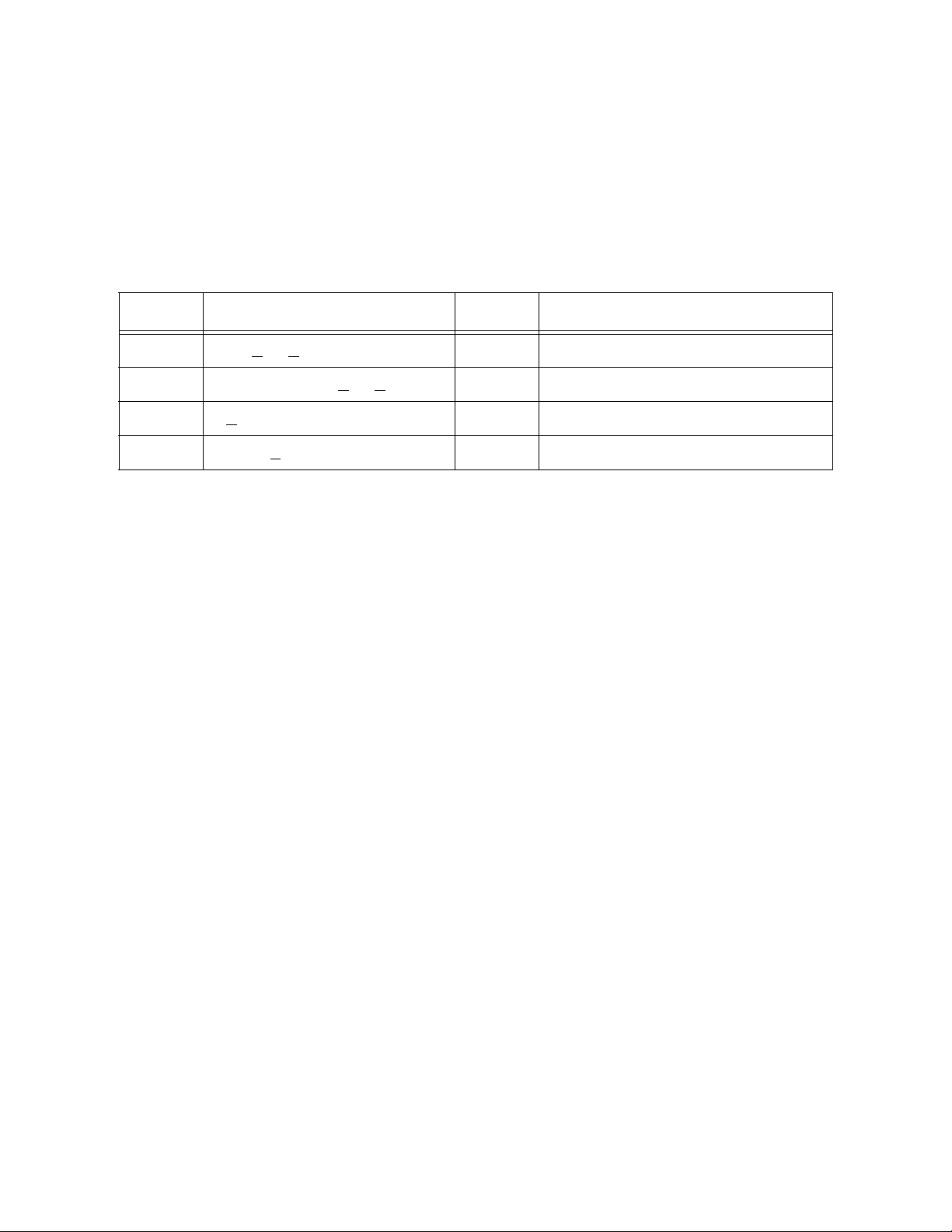
Model 3095FB Multivariable Transmitter with Modbus Protocol
Modbus Protocol Guide
5.3.1.1 Method 1: Define the Endpoints
The host can configure the scaled integers just by defining the endpoints (x1,y1 and x2,y2)
for the line shown Figure 5-1 .
The 3095FB will reject endpoints that do not conform to the following limits.
Table 5-6 Limits for Defining Endpoints
Variable Valid Range Type Description
x
1
x
2
y
1
y
2
LRL < x1 < (x2 - min_span) F32 Minimum Measured Value
(x1 + min_span) < x2 < URL F32 Maximum Measured Value
0 < y1 < y
2
U16 Minimum Scaled Integer
y1 < y2 < 65534 U16 Maximum Scaled Integer
The values for x1 and x2 should be configured for the current unit codes. If the host
changes unit codes after the scaled integers are configured using Method 1, the values for
x1 and x2 will be changed to reflect the new unit codes.
Page 36 of 79
Page 68

Model 3095FB Multivariable Transmitter with Modbus Protocol
Modbus Protocol Guide
Table 5-7 PV Scaled Integer Y Value
Modbus Access
Address
Address
Type
0188 Holding
register
0189 Holding
Attributes
Functional
Area
RW PV Scaled
Integers
RW DP_y2
DESCRIPTION
Data / Control
DP_y1
register
0190 Holding
RW SP_y1
register
0191 Holding
RW SP_y2
register
0192 Holding
RW PT_y1
register
0193 Holding
RW PT_y2
register
*Attributes: R/W = Read/Write, RO = Read Only, WP = Write Protected
**These registers are available at multiple Modbus addresses (see Section 2.3 located in
the Modbus Protocol Guide)
Page 37 of 79
Page 69

Model 3095FB Multivariable Transmitter with Modbus Protocol
Modbus Protocol Guide
Table 5-8 PV Scaled Integer X Value
Address
0469,
0470
0471,
Modbus Access
Address
Type
Attributes
Functional
Area
FP register RW PV Scaled
Integers
FP register RW DP_x2
DESCRIPTION
Data / Control
DP_x1
0472
0473,
FP register RW SP_x1
0474
0475,
FP register RW SP_x2
0476
0477,
FP register RW PT_x1
0478
0479,
FP register RW PT_x2
0480
*Attributes: R/W = Read/Write, RO = Read Only, WP = Write Protected
**These registers are available at multiple Modbus addresses (see Section 2.3)
5.3.1.2 Method 2: Define Scale and Offset
To configure the integer scaling of PVs using Method 2, follow this procedure:
1. Set a maximum integer.
2. Calculate the scale factor for each PV.
3. Calculate the offset for each PV
4. Write the values calculated above to the corresponding registers.
The following formula is used to calculate the scale factor and offset:
[Equation 2] y = A(x) - (B - 32,768)
Where: y = scaled integer output (see Table 5-4)
x = measured value of PV in current units (see Table 5-1)
A = scale factor (see Table 5-10)
B = offset of scaled integer (see Table 5-10)
Page 38 of 79
Page 70

Model 3095FB Multivariable Transmitter with Modbus Protocol
Modbus Protocol Guide
Table 5-9 PV Scaled Integer Maximum Integer
Modbus Access
Address
Address
Type
125 Holding
register
Attributes
Functional
Area
RW PV Scaled
Integers
DESCRIPTION
Data / Control
Maximum Integer (applies to all
PVs)
*Attributes: R/W = Read/Write, RO = Read Only, WP = Write Protected
**These registers are available at multiple Modbus addresses (see Section 2.3 located in
the Modbus Protocol Guide)
Maximum Integer: The maximum integer is the upper limit for the scaled integer output.
If the measured value derives an integer higher than the maximum integer or lower than 0,
the maximum integer plus one will be returned. Also, if any of the error conditions
described in Section 5.3.2 occur the affected scaled integers will be set to the maximum
integer plus one. The maximum integer can be any value from 0 to 65534. The default
maximum integer is 65534.
Page 39 of 79
Page 71

Model 3095FB Multivariable Transmitter with Modbus Protocol
Modbus Protocol Guide
Table 5-10 Scale Factors and Offsets
Modbus Access
Address
Address
Type
0198 Holding
register
0199 Holding
Attributes
Functional
Area
RW PV Scaled
Integers
RW DP Offset
DESCRIPTION
Data / Control
DP Scale Factor
register
0200 Holding
RW SP Scale Factor
register
0201 Holding
RW SP Offset
register
0202 Holding
RW PT Scale Factor
register
0203 Holding
RW PT Offset
register
*Attributes: R/W = Read/Write, RO = Read Only, WP = Write Protected
**These registers are available at multiple Modbus addresses (see Section 2.3)
Scale Factor: The scale factor is the linear slope of the line represented in Figure 5-1 .
The scale factor is the ratio of the change of the scaled integers compared to the change of
the measured process variable.
The Scale Factor and Offset must be configured for the current unit codes. If the unit
codes are changed the Scale Factor and Offset must be recalculated.
[Equation 3] A = (y2 - y1)/(x2 - x1)
Offset: The offset is calculated using [Equation 4].
[Equation 4] B = A(x1) + 32768 - y
Page 40 of 79
1
Page 72

Model 3095FB Multivariable Transmitter with Modbus Protocol
Modbus Protocol Guide
5.3.2 Scaled Integer Error Conditions
If an error occurs the scaled output will be set to either y2 + 1 (Method 1) or maximum integer + 1 (Method 2).
5.3.2.1 General Exceptions that Apply to All Scaled Outputs
Table 5-11 General Sensor Errors
Attributes Description
AD ST signal is above Upper Internal Limit
AD ST signal is below Lower Internal Limit
AD Sensor module is NOT updating
AD Sensor microprocessor does not respond
If the calculated scaled output is greater than y2 (Method 1) or less than y1 (Method 1) the
value returned is y2 + 1.
If the calculated scaled output is greater than the maximum integer (Method 2) or less than
zero (Method 2) the value returned is maximum integer + 1.
5.3.2.2 Exceptions that Apply to DP
The following exceptions apply only to the differential pressure.
Table 5-12 DP Exceptions
Attributes Description
AD DP signal above Upper Range Limit + 10%
W DP signal above Upper Range Limit
W DP signal below Lower Range Limit
AD DP signal below Lower Range Limit - 10%
AD SP signal above Upper Range Limit + 10%
AD SP signal below Lower Range Limit - 10%
AD SP sensor shorted
AD SP signal is unreasonable - open bridge
Page 41 of 79
Page 73

Model 3095FB Multivariable Transmitter with Modbus Protocol
5.3.2.3 Exceptions that Apply to SP
The following exceptions apply only to the static pressure.
Table 5-13 SP Exceptions
Attributes Description
AD SP signal above Upper Range Limit + 10%
W SP signal above Upper Range Limit
W SP signal below Lower Range Limit
AD SP signal below Lower Range Limit - 10%
AD SP sensor shorted
AD SP signal is unreasonable - open bridge
Modbus Protocol Guide
5.3.2.4 Exceptions that Apply to PT
The following exceptions apply only to the process temperature.
Table 5-14 PT Exceptions
Attributes Description
AD PT signal above Upper Range Limit + 10%
W PT signal above Upper Range Limit
W PT signal below Lower Range Limit
AD PT signal below Lower Range Limit - 10%
5.4 Untrimmed and Corrected Process Variables
A 24 bit integer will be provided that shows an integer representation of the process variables
before they have been trimmed and damped.
The formula for interpreting the 24 bit numbers is shown below.
output = (input - 8388608) * URL
7601920
Where:
input = Untrimmed and Corrected Process Variable
output = Scaled Process Variable
Page 42 of 79
Page 74

Model 3095FB Multivariable Transmitter with Modbus Protocol
Modbus Protocol Guide
Table 5-15 Untrimmed and Corrected Process Variables
Address
0076,
0077
Modbus Access
Address
Type
Input register
Attributes
Functional
RO PVs
Untrimmed
Area
DESCRIPTION
Data / Control
DP (3 bytes)
and Cor-
0078,
0079
0080,
0081
Input register
Input register
RO SP (3 bytes)
rected
RO PT (3 bytes)
*Attributes: R/W = Read/Write, RO = Read Only, WP = Write Protected
**These registers are available at multiple Modbus addresses (see Section 2.3 located in
the Modbus Protocol Guide)
5.5 Process Variable Default Values (PT)
The 3095FB allows for the enabling and disabling of the PT input. To disable the PT input
turn the RTD present coil OFF. Likewise to enable the PT input turn the RTD present coil ON.
If the RTD present coil is OFF the User Entered PT Value is used.
When entering a User Entered PT Value the current PT unit code is used. If the current PT unit
code is oF then entering a floating point value of 60 in the register pair 455, 456 would set the
User Entered PT Value to 60 oF. If at a later time the PT unit code is changed to oC then the
User Entered PT Value will read as 15.556 oC.
Page 43 of 79
Page 75

Model 3095FB Multivariable Transmitter with Modbus Protocol
Modbus Protocol Guide
Table 5-16 RTD Present
Address
Modbus Access
Address
Type
Attributes
Functional
Area
DESCRIPTION
Data / Control
0004 Coil R/W, WP RTD present (0=not present, 1 =
present)
*Attributes: R/W = Read/Write, RO = Read Only, WP = Write Protected
**These registers are available at multiple Modbus addresses (see Section 2.3 located in
the Modbus Protocol Guide)
Table 5-17 User Entered PT Value
Address
Modbus Access
Address
Type
Attributes
Functional
Area
DESCRIPTION
Data / Control
0455,
0456
FP register R/W, WP User Entered PT Value
Default = 60 oF
*Attributes: R/W = Read/Write, RO = Read Only, WP = Write Protected
**These registers are available at multiple Modbus addresses (see Section 2.3 located in
the Modbus Protocol Guide)
Page 44 of 79
Page 76

Model 3095FB Multivariable Transmitter with Modbus Protocol
Modbus Protocol Guide
6.0 Calibration
6.1 Calibration
Each process variable in the 3095FB [differential pressure (DP), static pressure (SP), and process temperature (PT)] can be trimmed. Two types of trims can be performed; offset (zero)
trim and slope (span) trim. To perform a trim the user only has to write the applied value to the
Modbus register while applying an accurate pressure or temperature to the 3095FB. For accurate trimming the user should wait for the process variable to stabilize before attempting to
trim the transmitter. The 3095FB will do all the calculations needed to trim the transmitter.
The host should never write the offset (zero) and slope (span) trims at the same time.
For example, if the user wants to trim the DP from 0 to 100 inches of H2O@60 F there are
four steps.
1. Apply the offset(zero) DP to the transmitter. In this case apply 0 inches of H2O@60 F
and wait for the transmitter to stabilize.
2. Write the IEEE 754 floating point number to the register pair 437, 438. In this case
write a zero to the register pair.
3. Apply the slope(span) DP to the transmitter. In this case apply 100 inches of H2O@60
F and wait for the transmitter to stabilize.
4. Write the IEEE 754 floating point number to the register pair 439,440. In this case
write the number 100 to the register pair.
Table 6-1 Calibration
Address
0437,
0438
0439,
0440
Modbus Access
Address
Type
FP register R/W, WP DP calibra-
FP register R/W, WP DP slope (span)
Attributes
Functional
Area
tion
DESCRIPTION
Data / Control
DP offset (zero)
0443,
0444
0445,
0446
FP register R/W, WP SP calibra-
tion
FP register R/W, WP SP slope (span)
Page 45 of 79
SP offset (zero)
Page 77

Model 3095FB Multivariable Transmitter with Modbus Protocol
Modbus Protocol Guide
Table 6-1 Calibration
Address
0449,
0450
0451,
Modbus Access
Address
Type
Attributes
Functional
Area
FP register R/W, WP PT calibra-
tion
FP register R/W, WP PT slope (span)
DESCRIPTION
Data / Control
PT offset (zero)
0452
*Attributes: R/W = Read/Write, RO = Read Only, WP = Write Protected
**These registers are available at multiple Modbus addresses (see Section 2.3 located in
the Modbus Protocol Guide)
6.1.1 Calibration Flag
A Modbus coil has been provided as a way of flagging the transmitter as being in a Calibration state. This coil is used only for informational use and does not affect the internal operation of the 3095FB. The host has complete control of the Calibration Flag. When the
Calibration Flag is set, the corresponding status bit will turn ON.
It is recommended that this flag be turned on at the start of calibration, and then turned off
when the calibration is complete. The Calibration Flag is useful if for some reason the person performing a calibration on the 3095FB gets called away in the middle of the calibration. The 3095FB may be in an unknown state, such as vented to atmosphere. If the
Calibration Flag is set, the host that is polling the 3095FB will be able to see the Calibration
status bit and mark the incoming data as unreliable.
Table 6-2 Calibration Flag
Address
Modbus Access
Address
Type
Attributes
Functional
Area
DESCRIPTION
Data / Control
0003 Coil R/W, WP Calibration Calibration Flag
*Attributes: R/W = Read/Write, RO = Read Only, WP = Write Protected
**These registers are available at multiple Modbus addresses (see Section 2.3 located in
the Modbus Protocol Guide)
Page 46 of 79
Page 78

Model 3095FB Multivariable Transmitter with Modbus Protocol
Modbus Protocol Guide
6.2 Damping
A damping factor can also be entered for each process variable. The damping will smooth the
process variable reading when there are rapid input variations. The following damping values
(in seconds) are available. The underlined value is the default.
0.108 0.216 0.432 0.864 1.728 3.456 6.912 13.824 27.648
If the new damping value, sent by the host, is not one of the valid options, the closest damping
value will be selected. Only values of 0 to 30 seconds will be accepted by the 3095FB. If the
value is outside of this range a Modbus exception Illegal Data Value (03) will be returned.
Table 6-3 Damping
Address
0441,
Modbus Access
Address
Type
Attributes
Functional
Area
FP register R/W, WP Damping DP damping
DESCRIPTION
Data / Control
0442
0447,
FP register R/W, WP SP damping
0448
0453,
FP register R/W, WP PT damping
0454
*Attributes: R/W = Read/Write, RO = Read Only, WP = Write Protected
**These registers are available at multiple Modbus addresses (see Section 2.3 located in
the Modbus Protocol Guide)
Page 47 of 79
Page 79

Model 3095FB Multivariable Transmitter with Modbus Protocol
Modbus Protocol Guide
6.3 Restore Factory Trim Defaults
Triggering the following coils will cause the 3095FB to revert to the Factory Trim Defaults.
The 3095FB must then be recalibrated.
Table 6-4 Reset Factory Trim Defaults
Modbus Access
Address
Address
Type
Attributes
Functional
Area
0031 Coil R/W, WP Reset Trim
DESCRIPTION
Data / Control
DP
to Factory
0032 Coil R/W, WP SP
Defaults
0033 Coil R/W, WP PT
*Attributes: R/W = Read/Write, RO = Read Only, WP = Write Protected
**These registers are available at multiple Modbus addresses (see Section 2.3 located in
the Modbus Protocol Guide)
Page 48 of 79
Page 80

Model 3095FB Multivariable Transmitter with Modbus Protocol
Modbus Protocol Guide
7.0 LCD Display Configuration
If the 3095FB includes an optional LCD display, the user may select which configuration
parameters to display. This is accomplished by the use of the display bit map. The rate at which
the LCD display is updated is also configurable between one and ten seconds.
Table 7-1 Transmitter Info
Modbus Access
Address
0126 Holding
0127,
0128
Address
Type
register
Holding
register
*Attributes: R/W = Read/Write, RO = Read Only, WP = Write Protected
**These registers are available at multiple Modbus addresses (see Section 2.3
DESCRIPTION
Attributes
R/W, WP LCD LCD Update Rate (1 - 10 seconds)
R/W, WP LCD Display Bit Mask
located in the Modbus Protocol Guide)
Functional
Area
0x0000 0001
0x0000 0002
0x0000 0004
0x0000 0008
Data / Control
Differential Pressure
Static Pressure
Process Temperature
Communication Setup
Page 49 of 79
Page 81

Model 3095FB Multivariable Transmitter with Modbus Protocol
Modbus Protocol Guide
8.0 Exception Handling
There are a number of exceptions that may occur. The severity of these may range from a
warning to a critical error. The LCD (if present) will display the error condition depending on
the attributes of the exception. The following tables define the criteria and list the types of
alarms and their attributes.
8.1 Diagnostic Status Bits
There are a number of diagnostic status bits that can give information about the status of the
transmitter. The user can read the status bits as discrete inputs, input registers, or as floating
point registers. This gives the user a variety of ways to get the status of the transmitter. These
registers contain the exact same information. The status registers are placed next to the Floating Point PVs. In a polling environment the host should retrieve the PVs and the Status
Registers in a single query. Table 8.1, on page 50 shows the register layout of the diagnostic
status bits in each form (discrete input, input register, and floating point register). The float-
ing point status registers are in a bit mapped format.
A value of zero will indicate that the condition is FALSE (OFF), and a value of one will indicate that the condition is TRUE (ON). All reserved bits will be forced to FALSE (OFF).
Meaning of Attributes:
A = Critical Alarm State (Critical Alarm status bit is set)
W = Warning State (Warning status bit is set)
D = LCD will display exception
Table 8-1 Mapping of Status Bits to Coils, Input Registers, and Floating Point Registers
Discrete
Input
Address
0050 0119 0407 15 D Calibration Flag
0051 14 Critical Alarm: The PVs may not be valid
0052 13 Warning: The PVs are outside specification
0053 12 AD DP signal above Upper Range Limit + 10%
0054 11 W DP signal above Upper Range Limit
Input
Register
Address
Floating
Point
Register
Address
Bit
Position Attributes
Description
0055 10 DP signal above Upper Operating Limit
0056 9 DP signal below Lower Operating Limit
0057 8 W DP signal below Lower Range Limit
Page 50 of 79
Page 82
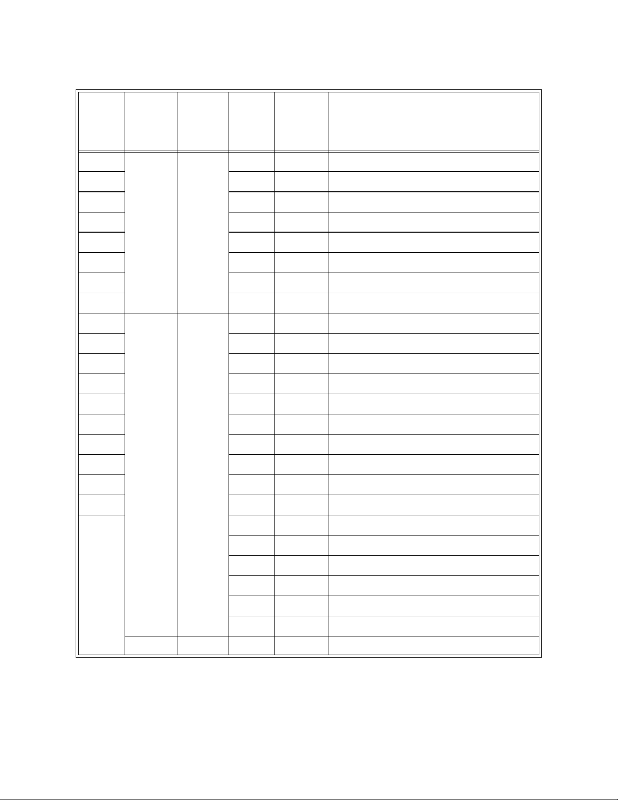
Model 3095FB Multivariable Transmitter with Modbus Protocol
Modbus Protocol Guide
Table 8-1 Mapping of Status Bits to Coils, Input Registers, and Floating Point Registers
Discrete
Input
Address
0058 0119
0059 6 AD SP signal above Upper Range Limit + 10%
0060 5 W SP signal above Upper Range Limit
0061 4 SP signal above Upper Operating Limit
0062 3 SP signal below Lower Operating Limit
0063 2 W SP signal below Lower Range Limit
0064 1 AD SP signal below Lower Range Limit - 10%
0065 0 AD SP sensor shorted
0066 0120 0408 15 AD SP signal is unreasonable - open bridge
0067 14 AD PT signal above Upper Range Limit + 10%
0068 13 W PT signal above Upper Range Limit
0069 12 PT signal above Upper Operating Limit
Input
Register
Address
(cont)
Floating
Point
Register
Address
0407
(cont)
Bit
Position Attributes
7 AD DP signal below Lower Range Limit - 10%
Description
0070 11 PT signal below Lower Operating Limit
0071 10 W PT signal below Lower Range Limit
0072 9 AD PT signal below Lower Range Limit - 10%
0073 8 AD RTD is disconnected
0074 7 AD ST signal is above Upper Internal Limit
0075 6 AD ST signal is below Lower Internal Limit
5 Reserved
4 Reserved
3 Reserved
Inputs
Not Available as Discrete
0121 0409 15 AD Sensor module is NOT updating
2 Reserved
1 Reserved
0 Reserved
Page 51 of 79
Page 83

Model 3095FB Multivariable Transmitter with Modbus Protocol
Modbus Protocol Guide
Table 8-1 Mapping of Status Bits to Coils, Input Registers, and Floating Point Registers
Discrete
Input
Address
Inputs
Not Available as Discrete
Input
Register
Address
0121 0409 15 AD Sensor module is NOT updating
0121
(cont)
Floating
Point
Register
Address
0409
(cont)
Bit
Position Attributes
14 Reserved
13 AD Sensor microprocessor does not respond
12 AD Sensor board eeprom burn failure
11 AD Sensor hardware incompatible with software
10 AD Sensor CRC error (Static Region)
9 AD Sensor CRC error (Dynamic Region)
8 Reserved
7 Reserved
6 Flash output board eeprom soft (recoverable)
error
5 AD Flash output board eeprom hard (non recover-
able) error
Description
4 Flash output board eeprom time out
3 Reserved
2 AD Nonvolatile Database CRC error
1 Write Protect Status
0 Reserved
**These registers are available at multiple Modbus addresses (see Section 2.3 located in the Modbus Protocol Guide)
Note: Not all of the diagnostic status bits are available as a discrete inputs. The rest of the diagnostic status bits can be read as
either an input register or as a floating point register.
8.1.1 Critical Alarm
The Critical Alarm status bit is linked to the status bits that could cause the PVs to be
incorrect. When a status bit with the Attribute A (Alarm) is set the Critical Alarm status bit
is also set.
8.1.2 Warning
The Warning status bit is linked to the status bits that signify that the transmitter may be
outside of specification. When a Status Bit with the Attribute W (Warning) is set the
Warning Status Bit is also set.
Page 52 of 79
Page 84

Model 3095FB Multivariable Transmitter with Modbus Protocol
Modbus Protocol Guide
9.0 Diagnostics
9.1 Self Test
A Self Test will verify the integrity of the some of the crucial areas of nonvolatile memory.
Table 9-1 Self Test
Modbus Access
Address
0001 Coil R/W Diagnos-
*Attributes: R/W = Read/Write, RO = Read Only, WP = Write Protected
**These registers are available at multiple Modbus addresses (see Section 2.3 located in
The procedure for performing a Self Test is as follows:
1. Force the Self Test coil ON. The 3095FB will return a normal response. The Self Test
takes approximately 500 ms.
2. Any errors that are detected will show up in the following status bits. The following
diagnostic status bits will be set or cleared by the Self Test, Master Reset, or cycling
power.
Address
Type
Attributes
the Modbus Protocol Guide)
Functional
Area
tics
DESCRIPTION
Data / Control
self test
Description
Sensor CRC error (Static Region)
Sensor CRC error (Dynamic Region)
Nonvolatile Database CRC error
Page 53 of 79
Page 85

Model 3095FB Multivariable Transmitter with Modbus Protocol
Modbus Protocol Guide
9.2 Master Reset
Activating the Master Reset coil performs a software reset of the 3095FB. This is similar to
shutting off the power and then reapplying power. The Master Reset takes approximately 500
milliseconds to complete.
Table 9-2 Master Reset
Modbus Access
Address
Address
Type
Attributes
Functional
Area
0002 Coil R/W Diagnos-
DESCRIPTION
Data / Control
Master Reset
tics
*Attributes: R/W = Read/Write, RO = Read Only, WP = Write Protected
**These registers are available at multiple Modbus addresses (see Section 2.3 located in
the Modbus Protocol Guide
9.3 Restoring Nonvolatile Database to Factory Defaults
Forcing the coils shown below to ON will reset the variables shown in the table below. The
transmitter must then be reset to ensure data integrity.
Table 9-3 Restoring Nonvolatile Database
Modbus Access
DESCRIPTION
Address
Address
Type
Attributes
0035 Coil R/W, WP Restore
Functional
Area
Restore Modbus Section 1
Nonvolatile Database
Transmitter Address
Turnaround Delay Time
Calibration Flag
0036 Coil R/W, WP Restore Modbus Section 2
Message
Descriptor
Transmitter Tag
User Entered Date
Page 54 of 79
Data / Control
1
50 ms
OFF
32 spaces
16 spaces
8 spaces
April 10, 1996
Page 86

Model 3095FB Multivariable Transmitter with Modbus Protocol
Modbus Protocol Guide
Table 9-3 Restoring Nonvolatile Database
Modbus Access
Address
Address
Type
Attributes
Functional
Area
0037 Coil R/W, WP Restore
Nonvolatile Database
Restore Sensor Section 1
DP unit code
SP unit code
DESCRIPTION
PT unit code
RTD present flag
User Entered PT Value
Lower Operating Limits
Upper Operating Limits
0039 Coil R/W, WP Restore Trim Section 1
DP damping
SP damping
PT damping
Scale Integer Method
DP_y1
DP_y2
SP_y1
SP_y2
PT_y1
PT_y2
DP_x1
DP_x2
SP_x1
SP_x2
PT_x1
PT_x2
Maximum Integer
DP Scale Factor
DP Offset
SP Scale Factor
SP Offset
PT Scale Factor
PT Offset
Data / Control
Inches H20 @ 60 F
psi
F
ON
60 F
Lower Range Limit
Upper Range Limit
.864
.864
.864
0
0
65534
0
65534
0
65534
-250
250
0
800
-40
400
65534
131
18
81
32768
148
26848
0041 Coil R/W, WP Restore
Nonvolatile Database
Restore LCD Section 1
LCD Bit Mask
LCD Update Rate
Page 55 of 79
0x0000 000f
3 seconds
Page 87

Model 3095FB Multivariable Transmitter with Modbus Protocol
Modbus Protocol Guide
Table 9-3 Restoring Nonvolatile Database
Modbus Access
Address
Address
Type
Attributes
Functional
Area
0049 Coil R/W, WP Restore
Nonvolatile Data-
Restore Mapping Section
Mapping Addresses
DESCRIPTION
Data / Control
base
*Attributes: R/W = Read/Write, RO = Read Only, WP = Write Protected
**These registers are available at multiple Modbus addresses (see Section 2.3 located in the Modbus
Protocol Guide
)
Page 56 of 79
Page 88

Model 3095FB Multivariable Transmitter with Modbus Protocol
Modbus Protocol Guide
Appendix A: Modbus Mapping Assignments by Data Types
Read/Write Coils
Modbus Access
Address
0001 Coil R/W Diagnos-
0002 Coil R/W Master Reset
0003 Coil R/W, WP Calibration Mode (set by host)
0004 Coil R/W, WP RTD present (0=not present, 1 =
0031 Coil R/W, WP Reset Trim
0032 Coil R/W, WP SP
0033 Coil R/W, WP PT
0035 Coil R/W, WP Restore
0036 Coil R/W, WP Restore Modbus Section 2
0037 Coil R/W, WP Restore Sensor Section 1
Address
Type
Attributes
Functional
Area
tics
to Factory
Defaults
Nonvolatile Database
DESCRIPTION
Data / Control
Self Test
present)
DP
Restore Modbus Section 1
0039 Coil R/W, WP Restore Trim Section 1
0041 Coil R/W, WP Restore LCD Section 1
0049 Coil R/W, WP Restore Mapping Section
*Attributes: R/W = Read/Write, RO = Read Only, WP = Write Protected
**These registers are available at multiple Modbus addresses (see Section 2.3 located in
the Modbus Protocol Guide)
Page 57 of 79
Page 89

Model 3095FB Multivariable Transmitter with Modbus Protocol
Read Only Discrete Inputs
Modbus Protocol Guide
Address
00500075
Modbus Access
Address
Type
Attributes
Functional
Coil RO Diagnos-
tics
Area
DESCRIPTION
Data / Control
Status bits
*Attributes: R/W = Read/Write, RO = Read Only, WP = Write Protected
**These registers are available at multiple Modbus addresses (see Section 2.3 located in
the Modbus Protocol Guide)
Floating Point Register Pairs
Address
Modbus Access
Address
Type
Attributes
Functional
Area
DESCRIPTION
Data / Control
03000400
0401,
0402
0403,
0404
0405,
0406
0407,
0408
0409,
0410
0411,
0412
0413,
0414
FP register Reserved for future use
FP register RO PVs DP
FP register RO SP
FP register RO PT
FP register RO Diagnos-
Status Bytes
tics
FP register RO Status Bytes
FP register RO Status Bytes
FP register RO Sensor lim-
DP upper range limit
its
Page 58 of 79
Page 90

Model 3095FB Multivariable Transmitter with Modbus Protocol
Floating Point Register Pairs
Modbus Protocol Guide
Address
0415,
0416
0417,
0418
0419,
0420
0421,
0422
0423,
0424
0425,
0426
0427,
0428
Modbus Access
Address
Type
Attributes
Functional
Area
FP register RO Sensor lim-
DESCRIPTION
Data / Control
DP lower range limit
its
FP register R/W, WP DP upper operating limit
FP register R/W, WP DP lower operating limit
FP register RO SP upper range limit
FP register RO SP lower range limit
FP register R/W, WP SP upper operating limit
FP register R/W, WP SP lower operating limit
0429,
0430
0431,
0432
0433,
0434
0435,
0436
0437,
0438
0439,
0440
0441,
0442
FP register RO PT upper range limit
FP register RO PT lower range limit
FP register R/W, WP PT upper operating limit
FP register R/W, WP PT lower operating limit
FP register R/W, WP DP calibra-
DP offset
tion
FP register R/W, WP DP slope
FP register R/W, WP DP damping
Page 59 of 79
Page 91

Model 3095FB Multivariable Transmitter with Modbus Protocol
Floating Point Register Pairs
Modbus Protocol Guide
Address
0443,
0444
0445,
0446
0447,
0448
0449,
0450
0451,
0452
0453,
0454
0455,
0456
Modbus Access
Address
Type
Attributes
Functional
Area
FP register R/W, WP SP calibra-
DESCRIPTION
SP offset
tion
FP register R/W, WP SP slope
FP register R/W, WP SP damping
FP register R/W, WP PT calibra-
PT offset
tion
FP register R/W, WP PT slope
FP register R/W, WP PT damping
FP register R/W, WP User
User Entered PT Value
Entered PT
Data / Control
0457,
FP register RO PVs ST
0458
0469,
0470
0471,
FP register RW PV Scaled
DP_x1
Integers
FP register RW DP_x2
0472
0473,
FP register RW SP_x1
0474
0475,
FP register RW SP_x2
0476
0477,
FP register RW PT_x1
0478
0479,
FP register RW PT_x2
0480
*Attributes: R/W = Read/Write, RO = Read Only, WP = Write Protected
**These registers are available at multiple Modbus addresses (see Section 2.3)
Page 60 of 79
Page 92

Model 3095FB Multivariable Transmitter with Modbus Protocol
Input Registers
Modbus Protocol Guide
Modbus Access
Address
Address
Type
0001 Input reg-
ister
0002 Input reg-
ister
0003 Input reg-
ister
0004 Input reg-
ister
0005,
0006
0007,
0008
Input register
Input register
0009 Input reg-
ister
DESCRIPTION
Attributes
RO Identify
Functional
Area
Data / Control
manufacturer’s code (U8)
transmitter
RO transmitter type code (U8)
RO output board software rev level
(U8)
RO sensor module software rev level
(U8+U8)
RO sensor module serial number
(U32)
RO transmitter serial number (U24)
RO hardware rev level (U8)
0010 Input reg-
ister
0011 Input reg-
ister
00120015
Input register
RO Modbus specific rev level (U8)
RO Sensor Type (U8)
RO Reserved
Page 61 of 79
Page 93

Model 3095FB Multivariable Transmitter with Modbus Protocol
Input Registers
Modbus Protocol Guide
Modbus Access
Address
Address
Type
0017 Input reg-
ister
0018 Input reg-
ister
0019 Input reg-
ister
0020 Input reg-
ister
0021 Input reg-
ister
0076,
0077
0078,
0079
0080,
0081
Input register
Input register
Input register
DESCRIPTION
Attributes
RO Transmit-
Functional
Area
Data / Control
DP Sensor Range Code (U8)
ter Info
RO SP Sensor Range Code (U8)
RO PT Sensor Range Code (U8)
RO Module Isolator Code (U8)
RO Module Fill Fluid Code (U8)
RO PVs
DP (U24)
Untrimmed
RO SP (U24)
and Corrected
Counts
RO PT (U24)
0082,
0083
0084,
0115
Input register
Input register
0116 Input reg-
ister
0117 Input reg-
ister
0118 Input reg-
ister
01190124
Input register
RO ST (U24)
RO Reserved
RO PV Scaled
DP
Integers
RO SP
RO PT
RO Diagnos-
Status Bytes(U16)
tics
Page 62 of 79
Page 94

Model 3095FB Multivariable Transmitter with Modbus Protocol
Input Registers
Modbus Protocol Guide
Modbus Access
Address
Address
Type
0145 Input reg-
ister
Attributes
Functional
Area
RO Communi-
cation Sta-
DESCRIPTION
Data / Control
Framing Error Count
tistics
0146 Input reg-
RO Noise Error Count
ister
0147 Input reg-
RO Overrun Error Count
ister
0148 Input reg-
RO CRC Error Count
ister
0149 Input reg-
RO Busy Count
ister
0150 Input reg-
RO Good Message Count
ister
*Attributes: R/W = Read/Write, RO = Read Only, WP = Write Protected
**These registers are available at multiple Modbus addresses (see Section 2.3 located in
the Modbus Protocol Guide)
Holding Registers
Modbus Access
Address
Address
Type
0016 Holding
register
0022 Holding
register
0023 Holding
register
0024 Holding
register
DESCRIPTION
Attributes
R/W, WP Transmit-
Functional
Area
Data / Control
transmitter address
ter Info
R/W, WP flange material code (U8)
R/W, WP flange type code (U8)
R/W, WP drain/vent code (U8)
Page 63 of 79
Page 95

Model 3095FB Multivariable Transmitter with Modbus Protocol
Holding Registers
Modbus Protocol Guide
Modbus Access
Address
Address
Type
0025 Holding
register
0026 Holding
register
0027 Holding
register
0028 Holding
register
0029 Holding
register
0030,
0031
Holding
register
0060 Holding
register
0061 Holding
register
DESCRIPTION
Attributes
R/W, WP Transmit-
Functional
Area
Data / Control
O-ring gasket material (U8)
ter info
R/W, WP remote seal type (U8)
R/W, WP remote seal fill fluid (U8)
R/W, WP remote seal isolator material (U8)
R/W, WP number of remote seals (U8)
R/W, WP user-entered date
R/W, WP Modbus
DP
units codes
R/W, WP SP
for PVs
0062 Holding
register
00630075
Holding
register
0125 Holding
register
0126 Holding
register
0127,
0128
Holding
register
0131 Holding
register
0132 Holding
register
R/W, WP PT
R/W, WP Reserved Reserved
R/W, WP PV Scaled
Maximum Integer
Integers
R/W, WP LCD LCD Update Rate
R/W, WP LCD Display Bit Mask
R/W, WP Communi-
Turnaround Delay Time
cations
R/W, WP Floating Point Format Code
Page 64 of 79
Page 96

Model 3095FB Multivariable Transmitter with Modbus Protocol
Holding Registers
Modbus Protocol Guide
Modbus Access
Address
Address
Type
0188 Holding
register
0189 Holding
register
0190 Holding
register
0191 Holding
register
0192 Holding
register
0193 Holding
register
0198 Holding
register
DESCRIPTION
Attributes
R/W, WP PV Scaled
Functional
Area
Data / Control
DP_y1
Integers
R/W, WP DP_y2
R/W, WP SP_y1
R/W, WP SP_y2
R/W, WP PT_y1
R/W, WP PT_y2
R/W, WP DP Scale Factor
0199 Holding
R/W, WP DP Offset
register
0200 Holding
R/W, WP SP Scale Factor
register
0201 Holding
R/W, WP SP Offset
register
0202 Holding
R/W, WP PT Scale Factor
register
0203 Holding
R/W, WP PT Offset
register
0204 Holding
R/W, WP Scaled Integer Method
register
*Attributes: R/W = Read/Write, RO = Read Only, WP = Write Protected
**These registers are available at multiple Modbus addresses (see Section 2.3 located in
the Modbus Protocol Guide)
Page 65 of 79
Page 97

Model 3095FB Multivariable Transmitter with Modbus Protocol
ASCII Character Strings
Modbus Protocol Guide
Address
00320035
0036-
Modbus Access
Address
Type
Attributes
Functional
Area
ASCII R/W, WP Transmit-
ter info
ASCII R/W, WP user-entered descriptor(U8x16)
DESCRIPTION
Data / Control
user-entered tag (U8x8)
0043
0044-
ASCII R/W, WP user entered message (U8x32)
0059
*Attributes: R/W = Read/Write, RO = Read Only, WP = Write Protected
**These registers are available at multiple Modbus addresses (see Section 2.3 located in
the Modbus Protocol Guide)
Page 66 of 79
Page 98

Model 3095FB Multivariable Transmitter with Modbus Protocol
Appendix B: Modbus Mapping Assignments by Register
Coils and Discrete Inputs
Modbus Protocol Guide
Modbus Access
Address
0001 Coil R/W Diagnos-
0002 Coil R/W Master Reset
0003 Coil R/W, WP Calibration Mode (set by host)
0004 Coil R/W, WP RTD present (0=not present, 1 =
0031 Coil R/W, WP Reset Trim
0032 Coil R/W, WP SP
0033 Coil R/W, WP PT
0035 Coil R/W, WP Restore
0036 Coil R/W, WP Restore Modbus Section 2
0037 Coil R/W, WP Restore Sensor Section 1
Address
Type
Attributes
Functional
Area
tics
to Factory
Defaults
Nonvolatile Database
DESCRIPTION
Data / Control
Self Test
present)
DP
Restore Modbus Section 1
0039 Coil R/W, WP Restore Trim Section 1
0041 Coil R/W, WP Restore LCD Section 1
0049 Coil R/W, WP Restore Mapping Section
00500075
**These registers are available at multiple Modbus addresses (see Section 2.3 located in
Coil RO Diagnos-
tics
*Attributes: R/W = Read/Write, RO = Read Only, WP = Write Protected
the Modbus Protocol Guide)
Page 67 of 79
Status bits
Page 99

Model 3095FB Multivariable Transmitter with Modbus Protocol
Modbus Protocol Guide
Input and Holding Registers (includes Floating Point and ASCII registers)
Modbus Access
Address
Address
Type
0001 Input reg-
ister
0002 Input reg-
ister
0003 Input reg-
ister
0004 Input reg-
ister
0005,
0006
0007,
0008
Input register
Input register
0009 Input reg-
ister
DESCRIPTION
Attributes
RO Identify
Functional
Area
Data / Control
manufacturer’s code (U8)
transmitter
RO transmitter type code (U8)
RO output board software rev level
(U8)
RO sensor module software rev level
(U8+U8)
RO sensor module serial number
(U32)
RO transmitter serial number (U24)
RO hardware rev level (U8)
0010 Input reg-
ister
0011 Input reg-
ister
00120015
Input register
0016 Holding
register
RO Modbus specific rev level (U8)
RO Sensor Type (U8)
RO Reserved
R/W, WP Transmit-
Transmitter Polling Address
ter info
Page 68 of 79
Page 100

Model 3095FB Multivariable Transmitter with Modbus Protocol
Modbus Protocol Guide
Input and Holding Registers (includes Floating Point and ASCII registers)
Modbus Access
Address
Address
Type
0017 Input reg-
ister
0018 Input reg-
ister
0019 Input reg-
ister
0020 Input reg-
ister
0021 Input reg-
ister
0022 Holding
register
0023 Holding
register
DESCRIPTION
Attributes
RO Transmit-
Functional
Area
Data / Control
DP Sensor Range Code (U8)
ter Info
RO SP Sensor Range Code (U8)
RO PT Sensor Range Code (U8)
RO Module Isolator Code (U8)
RO Module Fill Fluid Code (U8)
R/W, WP flange material code (U8)
R/W, WP flange type code (U8)
0024 Holding
register
0025 Holding
register
0026 Holding
register
0027 Holding
register
0028 Holding
register
0029 Holding
register
0030,
0031
Holding
register
R/W, WP drain/vent code (U8)
R/W, WP O-ring gasket material (U8)
R/W, WP remote seal type (U8)
R/W, WP remote seal fill fluid (U8)
R/W, WP remote seal isolator material (U8)
R/W, WP number of remote seals (U8)
R/W, WP user-entered date
Page 69 of 79
 Loading...