

Page 1
Reference Manual
00809-0100-4810, Rev DA
September 2007
Rosemount Compact Orifice
Flowmeter Series
www.rosemount.com
Page 2

Page 3

Reference Manual
Rosemount Compact Orifice
00809-0100-4810, Rev DA
September 2007
Flowmeter Series
Rosemount Compact Orifice Flowmeter Series
NOTICE
Read this manual before working with the product. For personal and system safety, and for
optimum product performance, make sure you thoroughly understand the contents before
installing, using, or maintaining this product.
The United States has two toll-free assistance numbers and one International number.
Customer Central
1-800-999-9307 (7:00 a.m. to 7:00 P.M. CST)
International
1-(952) 906-8888
National Response Center
1-800-654-7768 (24 hours a day)
Equipment service needs
The products described in this document are NOT designed for nuclear-qualified
applications. Using non-nuclear qualified products in applications that require
nuclear-qualified hardware or products may cause inaccurate readings.
For information on Emerson Process Management nuclear-qualified products, contact your
local Emerson Process Management Sales Representative.
This device is intended for use in temperature monitoring applications and should not be
used in control and safety applications.
www.rosemount.com
Page 4

Page 5

Reference Manual
00809-0100-4810, Rev DA
September 2007
Rosemount Compact Orifice
Flowmeter Series
Table of Contents
SECTION 1
Introduction
SECTION 2
Installation
Transmitter Information. . . . . . . . . . . . . . . . . . . . . . . . . . . . . . . . . . . . 1-1
Receiving and Inspection . . . . . . . . . . . . . . . . . . . . . . . . . . . . . . . . . . 1-1
Returning the Product. . . . . . . . . . . . . . . . . . . . . . . . . . . . . . . . . . . . . 1-1
Considerations . . . . . . . . . . . . . . . . . . . . . . . . . . . . . . . . . . . . . . . . . . 1-2
Functional . . . . . . . . . . . . . . . . . . . . . . . . . . . . . . . . . . . . . . . . . . . 1-2
Vibration Limits. . . . . . . . . . . . . . . . . . . . . . . . . . . . . . . . . . . . . 1-2
Safety Messages . . . . . . . . . . . . . . . . . . . . . . . . . . . . . . . . . . . . . . . . 2-1
Installation. . . . . . . . . . . . . . . . . . . . . . . . . . . . . . . . . . . . . . . . . . . . . . 2-1
Flowchart . . . . . . . . . . . . . . . . . . . . . . . . . . . . . . . . . . . . . . . . . . . . 2-1
Straight Run Requirements . . . . . . . . . . . . . . . . . . . . . . . . . . . . . . 2-3
Bolting a transmitter to the Rosemount 405 . . . . . . . . . . . . . . . . . 2-3
Location and Orientation. . . . . . . . . . . . . . . . . . . . . . . . . . . . . . . . . . . 2-4
Direct Mount Installation . . . . . . . . . . . . . . . . . . . . . . . . . . . . . . . . 2-4
Gas in Horizontal Pipes . . . . . . . . . . . . . . . . . . . . . . . . . . . . . . 2-4
Liquid or Steam in Horizontal Pipes . . . . . . . . . . . . . . . . . . . . . 2-5
Liquid in Vertical Pipes . . . . . . . . . . . . . . . . . . . . . . . . . . . . . . . 2-5
Gas in Vertical Pipes . . . . . . . . . . . . . . . . . . . . . . . . . . . . . . . . 2-6
Remote Mount Installation. . . . . . . . . . . . . . . . . . . . . . . . . . . . . . . 2-6
Gas in Vertical or Horizontal Pipes. . . . . . . . . . . . . . . . . . . . . . 2-6
Liquid or Steam in Vertical or Horizontal Pipes . . . . . . . . . . . . 2-7
Process Connections (Remote Mount Only) . . . . . . . . . . . . . . . . . 2-7
High Temperature Units (Option Code T) . . . . . . . . . . . . . . . . 2-8
Installation. . . . . . . . . . . . . . . . . . . . . . . . . . . . . . . . . . . . . . . . . . . . . . 2-8
Remote RTD Installation . . . . . . . . . . . . . . . . . . . . . . . . . . . . . . . 2-10
SECTION 3
Commissioning
SECTION 4
Operation and
Maintenance
Safety Messages . . . . . . . . . . . . . . . . . . . . . . . . . . . . . . . . . . . . . . . . 3-1
Direct Mount Applications . . . . . . . . . . . . . . . . . . . . . . . . . . . . . . . . . . 3-2
Liquid Service . . . . . . . . . . . . . . . . . . . . . . . . . . . . . . . . . . . . . . . . 3-2
Gas Service . . . . . . . . . . . . . . . . . . . . . . . . . . . . . . . . . . . . . . . . . . 3-3
Steam Service . . . . . . . . . . . . . . . . . . . . . . . . . . . . . . . . . . . . . . . . 3-4
Remote Mount Applications . . . . . . . . . . . . . . . . . . . . . . . . . . . . . . . . 3-5
Liquid Service . . . . . . . . . . . . . . . . . . . . . . . . . . . . . . . . . . . . . . . . 3-5
Gas Service . . . . . . . . . . . . . . . . . . . . . . . . . . . . . . . . . . . . . . . . . . 3-6
Steam Service . . . . . . . . . . . . . . . . . . . . . . . . . . . . . . . . . . . . . . . . 3-7
Safety Messages . . . . . . . . . . . . . . . . . . . . . . . . . . . . . . . . . . . . . . . . 4-1
Troubleshooting . . . . . . . . . . . . . . . . . . . . . . . . . . . . . . . . . . . . . . . . . 4-1
Check Flow Direction . . . . . . . . . . . . . . . . . . . . . . . . . . . . . . . . 4-3
Check Orientation. . . . . . . . . . . . . . . . . . . . . . . . . . . . . . . . . . . 4-3
Check Zero. . . . . . . . . . . . . . . . . . . . . . . . . . . . . . . . . . . . . . . . 4-3
Check Valves . . . . . . . . . . . . . . . . . . . . . . . . . . . . . . . . . . . . . . 4-3
Check Configuration/Scaling . . . . . . . . . . . . . . . . . . . . . . . . . . 4-3
Check 3095M Configuration. . . . . . . . . . . . . . . . . . . . . . . . . . . 4-3
RTD Maintenance. . . . . . . . . . . . . . . . . . . . . . . . . . . . . . . . . . . . . . . . 4-3
Remote Mount . . . . . . . . . . . . . . . . . . . . . . . . . . . . . . . . . . . . . 4-3
TOC-1
Page 6

Rosemount Compact Orifice
Flowmeter Series
Reference Manual
00809-0100-4810, Rev DA
September 2007
APPENDIX A
Reference Data
Rosemount 3051SFC Compact Orifice Flowmeter . . . . . . . . . . . . A-1
Specifications. . . . . . . . . . . . . . . . . . . . . . . . . . . . . . . . . . . . . . . . . . . . A-1
Performance . . . . . . . . . . . . . . . . . . . . . . . . . . . . . . . . . . . . . . . . . . A-1
Functional . . . . . . . . . . . . . . . . . . . . . . . . . . . . . . . . . . . . . . . . . . . . A-2
Physical . . . . . . . . . . . . . . . . . . . . . . . . . . . . . . . . . . . . . . . . . . . . . A-7
Installation Considerations . . . . . . . . . . . . . . . . . . . . . . . . . . . . . . .A-9
Dimensional Drawings . . . . . . . . . . . . . . . . . . . . . . . . . . . . . . . . . . . . A-11
Compact Orifice Plate
(Primary Element Type code P) . . . . . . . . . . . . . . . . . . . . . . . A-11
Conditioning Orifice Plate
(Primary Element Type code C) . . . . . . . . . . . . . . . . . . . . . . .A-11
Ordering Information . . . . . . . . . . . . . . . . . . . . . . . . . . . . . . . . . . . . . A-12
Rosemount 3051SFC Compact Orifice
Flowmeter Ordering Information . . . . . . . . . . . . . . . . . . . . . . . A-12
Rosemount 3095MFC Compact Orifice Mass Flowmeter . . . . . .A-16
Specifications. . . . . . . . . . . . . . . . . . . . . . . . . . . . . . . . . . . . . . . . . . . A-16
Performance . . . . . . . . . . . . . . . . . . . . . . . . . . . . . . . . . . . . . . . . . A-16
Functional . . . . . . . . . . . . . . . . . . . . . . . . . . . . . . . . . . . . . . . . . . . A-17
Physical . . . . . . . . . . . . . . . . . . . . . . . . . . . . . . . . . . . . . . . . . . . . A-19
Installation Considerations . . . . . . . . . . . . . . . . . . . . . . . . . . . . . .A-21
Dimensional Drawings . . . . . . . . . . . . . . . . . . . . . . . . . . . . . . . . . . . . A-24
Compact Orifice Plate
(Primary Element Type code P) . . . . . . . . . . . . . . . . . . . . . . . A-24
Conditioning Orifice Plate
(Primary Element Type code C) . . . . . . . . . . . . . . . . . . . . . . .A-24
Ordering Information . . . . . . . . . . . . . . . . . . . . . . . . . . . . . . . . . . . . . A-25
Rosemount 3095MFC Compact Orifice Mass
Flowmeter Ordering Information . . . . . . . . . . . . . . . . . . . . . . . A-25
Rosemount 405 Compact Orifice Primary Element . . . . . . . . . . . A-28
Specifications. . . . . . . . . . . . . . . . . . . . . . . . . . . . . . . . . . . . . . . . . . . A-28
Performance . . . . . . . . . . . . . . . . . . . . . . . . . . . . . . . . . . . . . . . . . A-28
Functional . . . . . . . . . . . . . . . . . . . . . . . . . . . . . . . . . . . . . . . . . . . A-28
Physical . . . . . . . . . . . . . . . . . . . . . . . . . . . . . . . . . . . . . . . . . . . . A-29
Installation Consideration . . . . . . . . . . . . . . . . . . . . . . . . . . . . . . . A-30
Dimensional Drawings . . . . . . . . . . . . . . . . . . . . . . . . . . . . . . . . . . . . A-33
Compact Orifice Plate
(Primary Element Type code P) . . . . . . . . . . . . . . . . . . . . . . . A-33
Conditioning Orifice Plate
(Primary Element Type code C) . . . . . . . . . . . . . . . . . . . . . . .A-33
Compact Orifice Plate
(Primary Element Type code P) . . . . . . . . . . . . . . . . . . . . . . . A-34
Conditioning Orifice Plate
(Primary Element Type code C) . . . . . . . . . . . . . . . . . . . . . . .A-34
Ordering Information . . . . . . . . . . . . . . . . . . . . . . . . . . . . . . . . . . . . . A-35
Rosemount 405 Compact Orifice
Primary Element Ordering Information . . . . . . . . . . . . . . . . . . A-35
Spare Parts . . . . . . . . . . . . . . . . . . . . . . . . . . . . . . . . . . . . . . . . . . . . A-37
Mounting Stud and Nut Kits. . . . . . . . . . . . . . . . . . . . . . . . . . . A-37
Gasket Kits . . . . . . . . . . . . . . . . . . . . . . . . . . . . . . . . . . . . . . .A-37
Miscellaneous . . . . . . . . . . . . . . . . . . . . . . . . . . . . . . . . . . . . . A-38
TOC-2
Page 7

Reference Manual
00809-0100-4810, Rev DA
September 2007
Rosemount Compact Orifice
Flowmeter Series
APPENDIX B
Product Certifications
3051SFC Product Certifications . . . . . . . . . . . . . . . . . . . . . . . . . . . . .B-1
Approved Manufacturing Locations . . . . . . . . . . . . . . . . . . . . . . . . B-1
European Directive Information . . . . . . . . . . . . . . . . . . . . . . . . . . . B-1
Ordinary Location Certification for FM . . . . . . . . . . . . . . . . . . . . . . B-2
Hazardous Locations Certifications . . . . . . . . . . . . . . . . . . . . . . . . B-2
North American Certifications . . . . . . . . . . . . . . . . . . . . . . . . . . B-2
European Certifications . . . . . . . . . . . . . . . . . . . . . . . . . . . . . . .B-2
Australian Certifications. . . . . . . . . . . . . . . . . . . . . . . . . . . . . . . B-4
IECEx Certifications . . . . . . . . . . . . . . . . . . . . . . . . . . . . . . . . .B-5
Combinations of Certifications. . . . . . . . . . . . . . . . . . . . . . . . . . B-6
3095MFC Product Certifications . . . . . . . . . . . . . . . . . . . . . . . . . . . . . B-6
ATEX Directive (94/9/EC) . . . . . . . . . . . . . . . . . . . . . . . . . . . . . B-6
European Pressure Equipment Directive (PED) (97/23/EC) . . .B-6
Electro Magnetic Compatibility (EMC) (89/336/EEC) . . . . . . . . B-7
Ordinary Location Certification for Factory Mutual . . . . . . . . . .B-7
Hazardous Locations Certifications . . . . . . . . . . . . . . . . . . . . . . . . B-7
North American Certifications . . . . . . . . . . . . . . . . . . . . . . . . . . B-7
European Certifications . . . . . . . . . . . . . . . . . . . . . . . . . . . . . . .B-8
Combinations of Certifications. . . . . . . . . . . . . . . . . . . . . . . . . . B-9
Installation Drawings . . . . . . . . . . . . . . . . . . . . . . . . . . . . . . . . . . . . . . B-9
TOC-3
Page 8

Rosemount Compact Orifice
Flowmeter Series
Reference Manual
00809-0100-4810, Rev DA
September 2007
TOC-4
Page 9

Reference Manual
00809-0100-4810, Rev DA
September 2007
Rosemount Compact Orifice
Section 1 Introduction
Transmitter Information . . . . . . . . . . . . . . . . . . . . . . . . . . . page 1-1
Receiving and Inspection . . . . . . . . . . . . . . . . . . . . . . . . . page 1-1
Returning the Product . . . . . . . . . . . . . . . . . . . . . . . . . . . . page 1-1
Considerations . . . . . . . . . . . . . . . . . . . . . . . . . . . . . . . . . . page 1-2
Flowmeter Series
TRANSMITTER
INFORMATION
RECEIVING
AND INSPECTION
RETURNING THE
PRODUCT
If the 405 primary element was ordered assembled to a Rosemount 3051S
transmitter, the new assembly is the Rosemount 3051SFC Compact Orifice
Flowmeter. See the Rosemount 3051S Series Pressure Transmitter reference
manual (document number 00809-0100-4801) for information regarding
transmitter installation, configuration, and operation.
If the 405 primary element was ordered assembled to a Rosemount 3095M
transmitter, the new assembly is the Rosemount 3095MFC Compact Orifice
Mass Flowmeter. See the Rosemount 3095M Mass Flow Transmitter
reference manual (document number 00809-0100-4801) for information
regarding transmitter installation, configuration, and operation.
Flowmeters are available in different models and with different options, so it is
important to inspect and verify that the appropriate model was delivered
before installation.
Upon receipt of the shipment, check the packing list against the material
received and the purchase order. All items are tagged with a model number,
serial number, and customer tag number. Report any damage to the carrier.
To expedite the return process, call the Rosemount National Response
Center toll-free at 800-654-7768. This center, available 24 hours a day, will
assist you with any needed information or materials.
The center will ask for the following information:
• Product model
• Serial numbers
• The last process material to which the product was exposed
www.rosemount.com
The center will provide
• A Return Material Authorization (RMA) number
• Instructions and procedures that are necessary to return goods that
were exposed to hazardous substances
NOTE
If a hazardous substance is identified, a Material Safety Data Sheet (MSDS),
required by law to be available to people exposed to specific hazardous
substances, must be included with the returned materials.
Page 10

Rosemount Compact Orifice
Flowmeter Series
Reference Manual
00809-0100-4810, Rev DA
September 2007
CONSIDERATIONS
Functional The Rosemount 405 produces the most accurate and repeatable
measurement when it is used in single-phase flow or steam flow above the
saturation temperature. Location of the 405 in pulsating flow will cause a
noisy signal. Vibration can also distort the output signal and compromise the
structural limits of the flowmeter.
Mount the 405 in a secure run of pipe as far as possible from pulsation
sources such as check valves, reciprocating compressors or pumps, and
control valves.
Install the 405 in the correct location within the piping branch to prevent
measurement inaccuracies caused by flow disturbances.
Maximum temperature for direct mount applications is 450 °F
(232 °C). Maximum temperature for remote mount applications is 850 °F
(454 °C).
Vibration Limits
Qualified per IEC61298-3 (1998) for field with high vibration level or pipeline
with high vibration level (10-60Hz 0.21mm displacement peak amplitude / 60 500Hz 3g).
The weight and length of the transmitter assembly shall not exceed 5.8 lbs
and 7.75-in.
1-2
Page 11

Reference Manual
00809-0100-4810, Rev DA
September 2007
Rosemount Compact Orifice
Flowmeter Series
Section 2 Installation
Safety Messages . . . . . . . . . . . . . . . . . . . . . . . . . . . . . . . . . page 2-1
Installation . . . . . . . . . . . . . . . . . . . . . . . . . . . . . . . . . . . . . . page 2-1
Location and Orientation . . . . . . . . . . . . . . . . . . . . . . . . . . page 2-4
SAFETY MESSAGES Instructions and procedures in this section may require special precautions to
ensure the safety of the personnel performing the operations. Please refer to
the following safety messages before performing any operation in this section.
Explosions could result in death or serious injury:
• Do not remove the transmitter cover in explosive atmospheres when the circuit is
live.
• Before connecting a HART Communicator in an explosive atmosphere, make sure
the instruments in the loop are installed in accordance with intrinsically safe or
non-incendive field wiring practices.
• Verify that the operating atmosphere of the transmitter is consistent with the
appropriate hazardous locations certifications.
• Both transmitter covers must be fully engaged to meet explosion-proof
requirements.
Failure to follow these installation guidelines could result in death or serious injury:
• Make sure only qualified personnel perform the installation.
The product may be hot while in service, potentially causing burns. Handle with care.
INSTALLATION
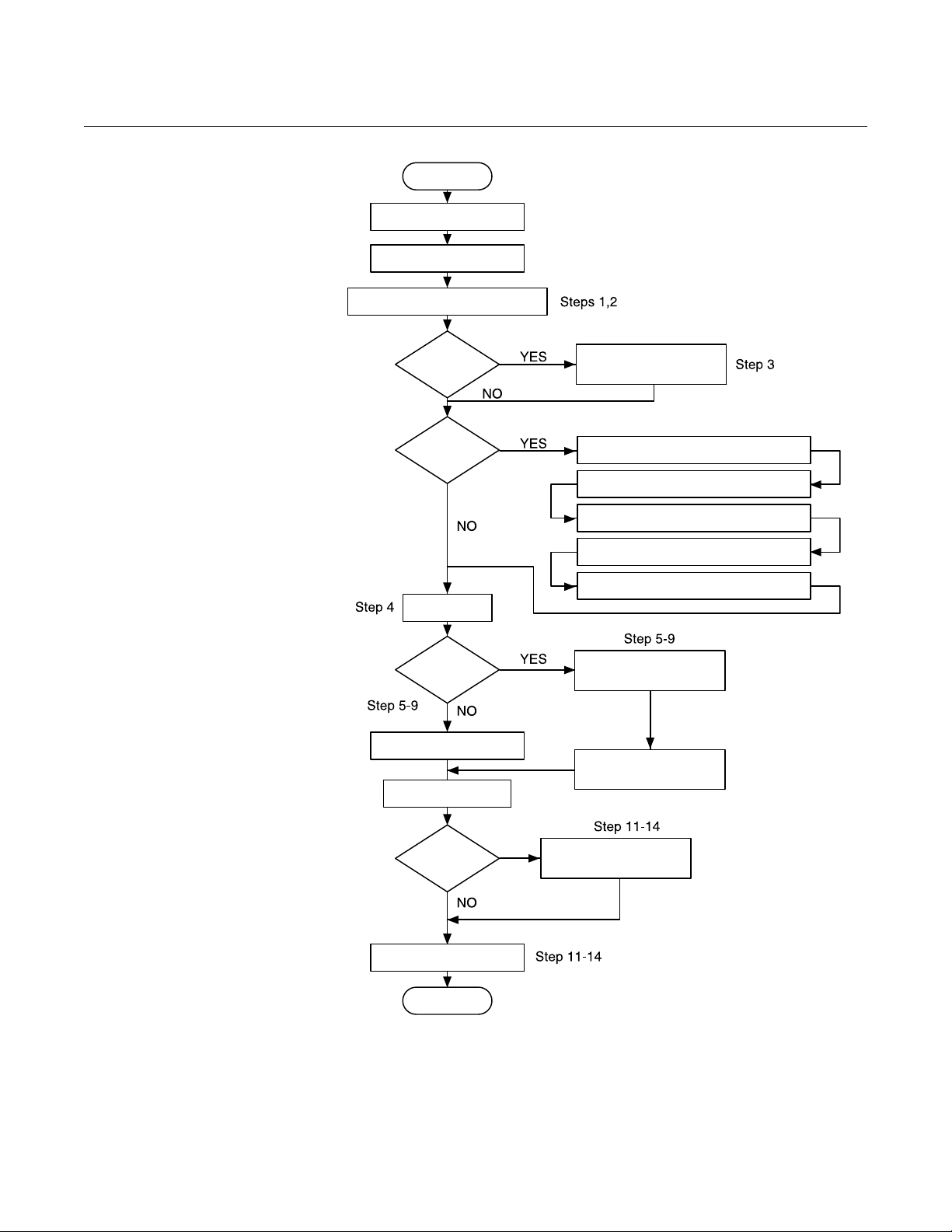
Flowchart Installation Chart page 2-2 is an installation flowchart that provides guidance
through the installation process. Following the figure, an installation checklist
has been provided to verify that all critical steps have been taken in the
installation process. The checklist numbers are indicated in the flowchart.
2-1
Page 12
Rosemount Compact Orifice
Start.
Unpack Instrument
Review Product
Manual.
Verify proper location.
Hazardous
Location?
Bench
Configure
Review Appendix B.
Configure write-protect and
failure alarm
Connect the bench power supply
Connect the instrument to a PC
Perform bench configuration tasks
(Optional) Perform bench
calibration tasks
Verify model
Remote
Mounted
Electronics?
Install electronics
Install flowmeter
Wire
Remote
Mounted
Electronics?
Finish.
Commission
Install hardware
Commission
Flowmeter Series
Figure 2-1. Installation Chart
Reference Manual
00809-0100-4810, Rev DA
October 2007
Handling
The product tag is not designed to withstand the weight of the orifice - do not
lift the product by the tag.
Do not lift the product by the orifice holes. Holes have sharp edges that may
cause personal injury. Lift the product by the casting neck.
2-2
Page 13

Reference Manual
00809-0100-4810, Rev DA
September 2007
Straight Run
Requirements
Rosemount Compact Orifice
Flowmeter Series
Table 2-1. 405C Straight Pipe
Requirements
Table 2-2. 405P Straight Pipe
Requirements
Bolting a transmitter to
the Rosemount 405
(1)
Beta
Single 90° bend or tee 2 2
Two or more 90 ° bends in the same plane 2 2
Two or more 90° bends in different plane 2 2
Up to 10° of swirl
Reducer (1 line size) 2 2
side of primary
Upstream (inlet)
Butterfly valve (75% open) 2 N/A
Downstream (outlet) side of primary
(1) (2) (3)
Beta
Reducer 5 12
Single 90° bend or tee 16 44
Two or more 90 ° bends in the same plane 10 44
Two or more 90° bends in different plane 50 60
Expander 12 28
Ball / Gate valve fully open 12 18
side of primary
Upstream (inlet)
(1) Consult an Emerson Process Management representative if disturbance is not listed.
(2) Recommended lengths represented in pipe diameters per ISO 5167.
(3) Refer to ISO 5167 for recommended lengths when using flow straighteners.
0.40 0.65
22
0.40 0.65
67
If the 405 is ordered separately from the 3051, or 3095M transmitter and will
be used in a direct mount configuration, it will need to be assembled to the
transmitter. Follow the directions below to assemble the 405 to a transmitter
with a coplanar configuration.
NOTE
Units shipped from the factory direct mounted are pressure tested and
characterized with the primary attached. Factory assembly is recommended
for best performance.
1. Remove the body bolts (4) from the transmitter.
2. Remove the socket head cap screws from the bottom of the coplanar
flange and remove the coplanar flange.
NOTE
Protect the transmitter sensing diaphragms and do not remove the o-rings in
transmitter sensor module.
3. Carefully assemble the 405 to the pressure transmitter sensor making
sure the “H” and “L” on transmitter and primary match.
4. Use studs and nuts supplied with the 405 to connect the transmitter
sensor to the manifold head of the 405.
5. Preload to 150 lbs/in. then final torque at 300 lbs/in.
2-3
Page 14
Rosemount Compact Orifice
FLANGE SCREWS
TRANSMITTER
SENSING MODULE
COPLANAR FLANGE
SENSING
DIAPHRAGMS
AND 0-RINGS
(DO NOT
DISTURB OR
REMOVE)
Flowmeter Series
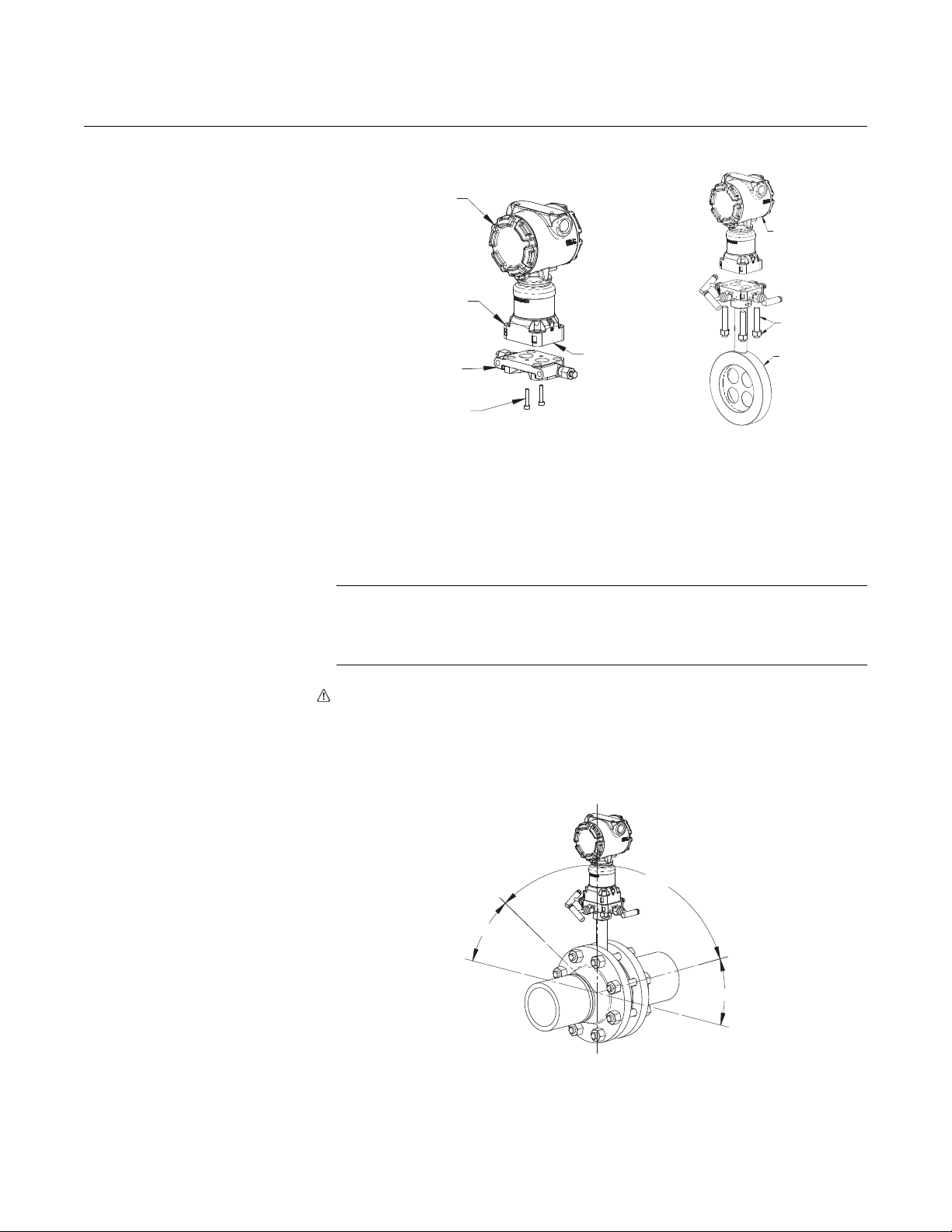
Figure 2-2. Bolting the 405
to a transmitter
Reference Manual
00809-0100-4810, Rev DA
September 2007
TRANSMITTER
STUDS
AND NUTS
ROSEMOUNT
405
LOCATION AND
ORIENTATION
The 405 has two mounting methods:
• integral mount (or direct mount)
• remote mount.
An integrally mounted 405 may be shipped with the transmitter already bolted
directly to the sensor.
Direct Mount Installation NOTE
The maximum acceptable temperature for direct mounting is 450 °F (232 C°).
Refer to "Location and Orientation" beginning on page 2-4 if the process
could potentially exceed this temperature.
Gas in Horizontal Pipes
The 405 should be mounted above the pipe to ensure that condensate does
not collect on the transmitter sensing diaphragms. Orient the unit within the
120° recommended zone as shown in Figure 2-3.
Figure 2-3. Direct Mount Gas in
Horizontal Pipes
120°
2-4
30°
30°
Page 15
Reference Manual
FLOW
00809-0100-4810, Rev DA
September 2007
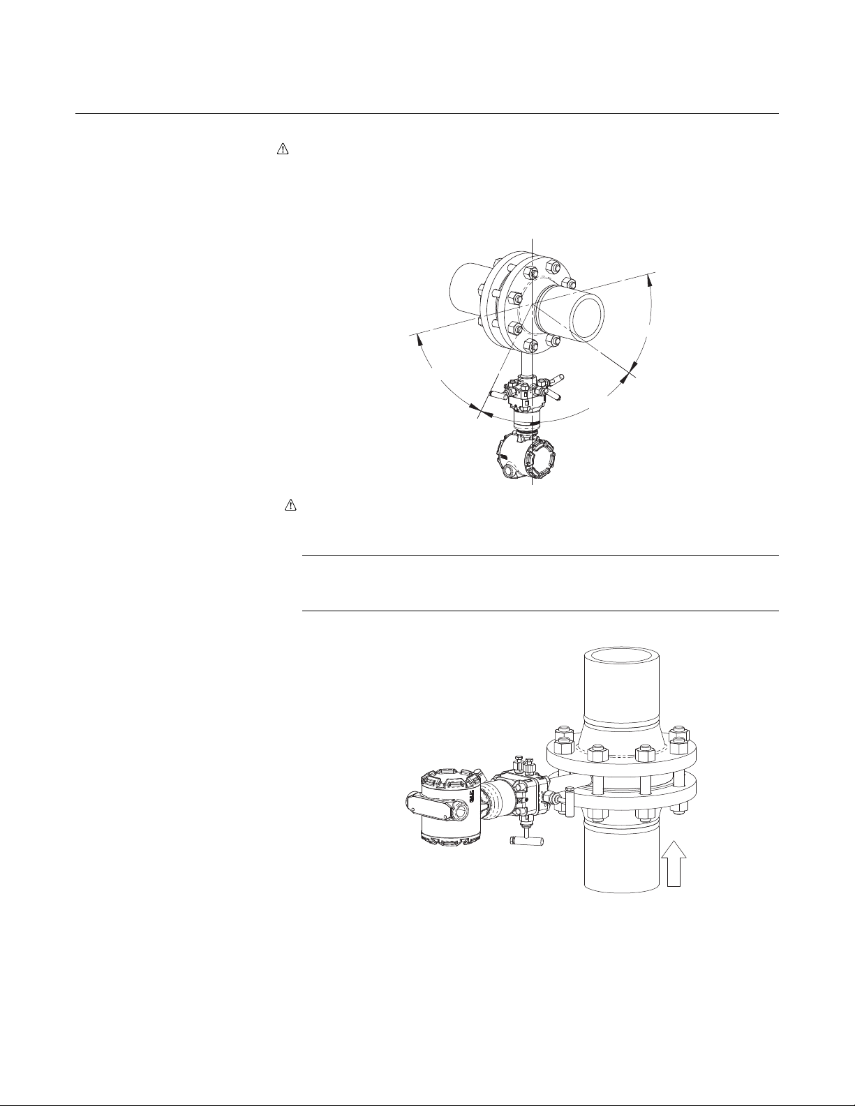
Figure 2-4. Direct Mount Liquid
or Steam in Horizontal Pipes
Rosemount Compact Orifice
Flowmeter Series
Liquid or Steam in Horizontal Pipes
The 405 should be mounted below the pipe to ensure that gases do not
collect on the transmitter sensing diaphragms. Orient the unit within the 80°
recommended zone as shown in Figure 2-4.
50°
50°
80°
Figure 2-5. Direct Mount Liquid
in Vertical Pipes
Liquid in Vertical Pipes
The 405 should be mounted with the vents on top to allow gas to be bled off.
NOTE
The 405 should not be used in vertical liquid or steam applications if the fluid
is flowing down.
2-5
Page 16
Rosemount Compact Orifice
FLOW
FLOW
Flowmeter Series
Gas in Vertical Pipes
The 405 should be mounted with vents on bottom to allow condensate
drainage.
NOTE
Due to drain vent orientation, a direct mount 405 should not be used in
vertical gas applications if the fluid is flowing up. Consider remote mounting
the pressure transmitter to facilitate condensate draining.
Figure 2-6. Direct Mount Gas in
Vertical Pipes
Reference Manual
00809-0100-4810, Rev DA
September 2007
Remote Mount
Installation
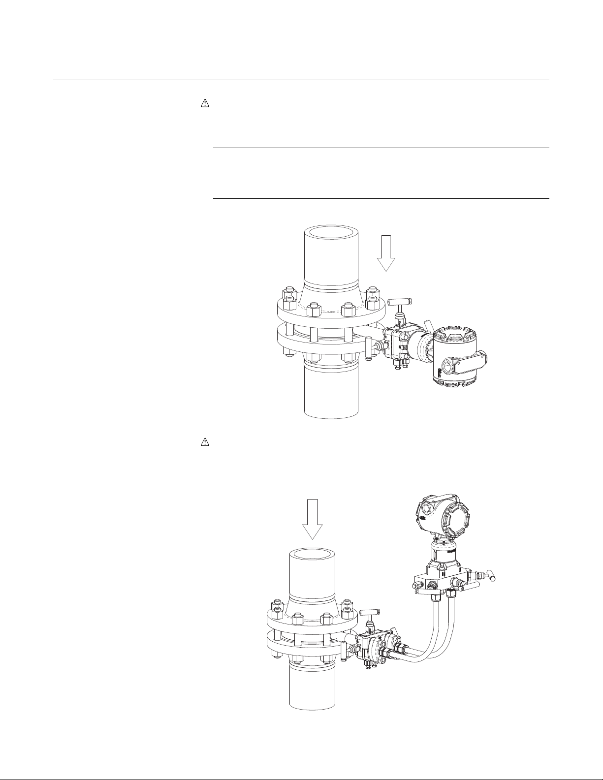
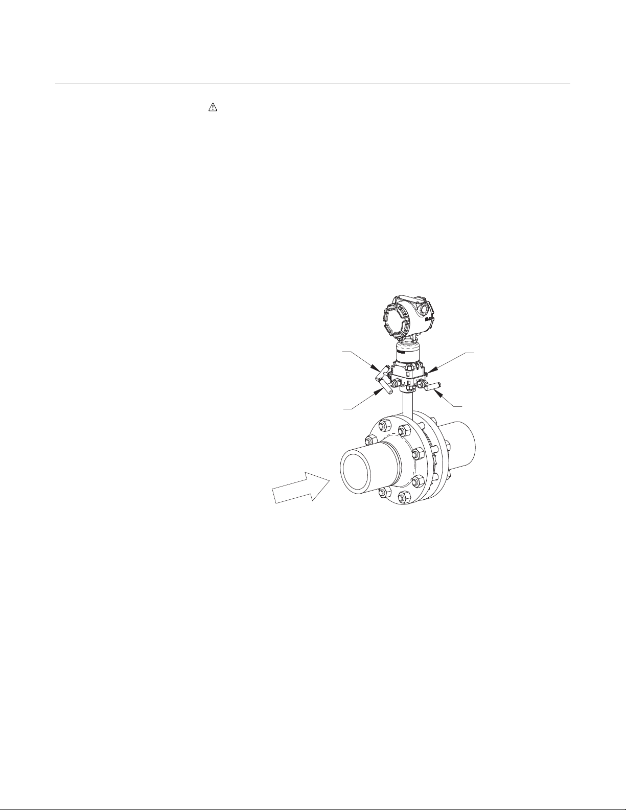
Figure 2-7. Remote Mount Gas
in Vertical or Horizontal Pipes
Gas in Vertical or Horizontal Pipes
Mount the transmitter above the 405 with the instrument lines sloping down.
2-6
Page 17
Reference Manual
00809-0100-4810, Rev DA
September 2007
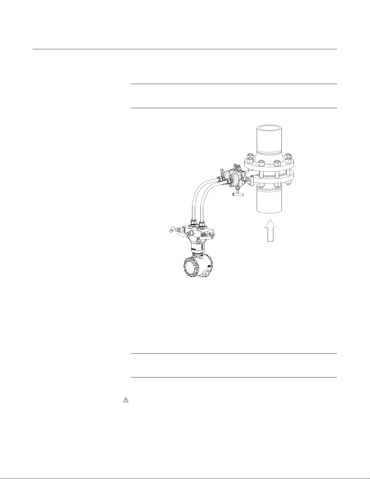
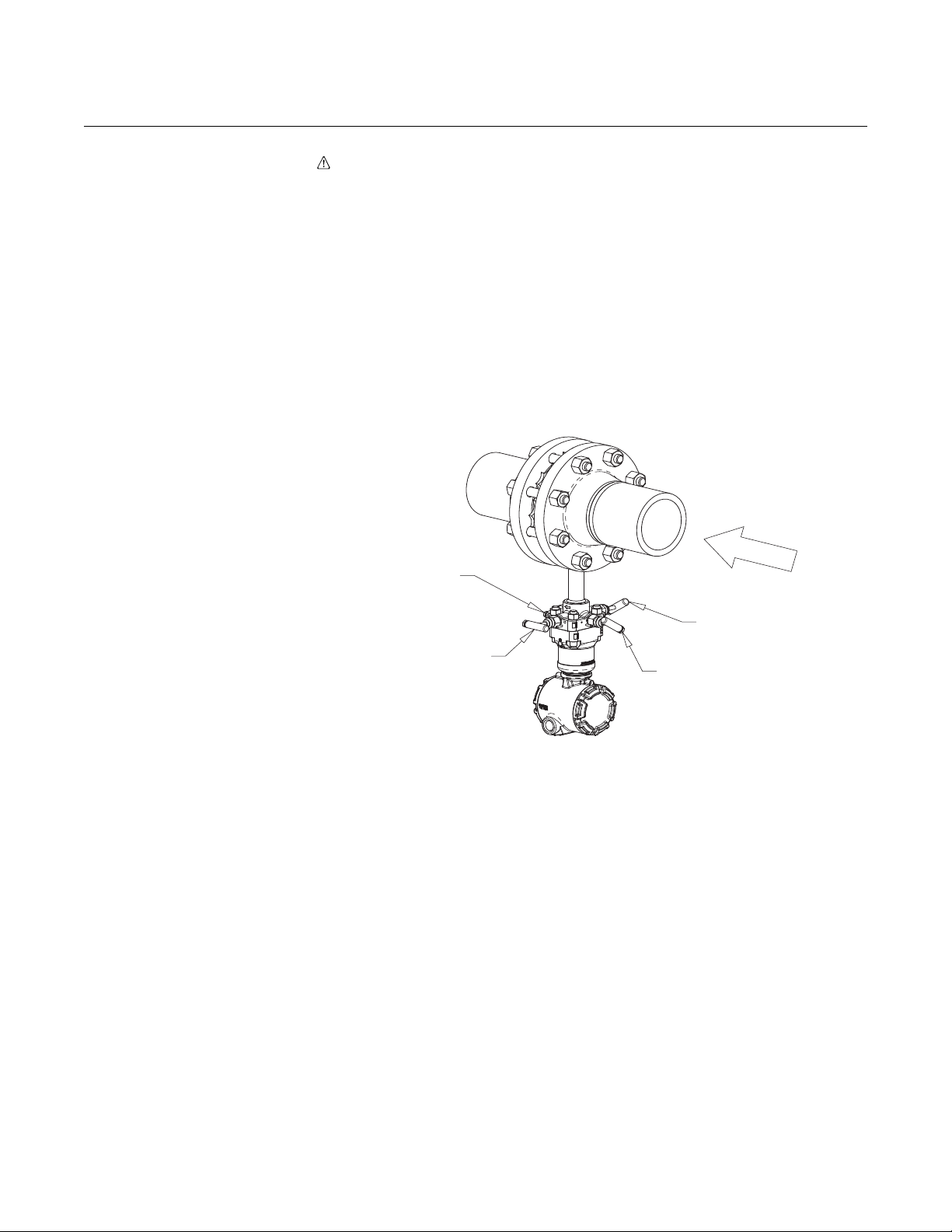
Figure 2-8. Remote Mount
Liquid in Vertical or Horizontal
Pipes
Rosemount Compact Orifice
Flowmeter Series
Liquid or Steam in Vertical or Horizontal Pipes
Mount the transmitter below the 405 with the instrument lines sloping up.
NOTE
The 405 should not be used in vertical liquid or steam applications if the fluid
is flowing down.
Process Connections
(Remote Mount Only)
FLOW
The 405 is available with either ¼-in. – 18 NPT connections (standard) or
½-in. – 14 NPT connections (option code E). The ½-in. connections can be
rotated to attain connection centers of 2-in. (51 mm), 2
¼-in. (57 mm). The threads are Class 2; use a lubricant or sealant when
making the process connections.
Ensure all four flange studs are installed and tightened prior to applying
pressure to prevent process leakage. When properly installed, the flange
studs will protrude through the top of the module housing.
NOTE
Do not attempt to loosen or remove the flange studs while the 405 is in
service.
Perform the following to install flange adapters to the head of the 405.
1. Place o-ring in the groove on bottom of the flange adapter.
2. Position flange adapters over NPT connections on the adapter plate.
3. Insert studs through 405 head, adapter plate, and flange adapters.
4. Thread nuts onto studs. Tighten nuts to 300 in-lbs. (34 N-m).
1
/8-in. (54 mm), or 2
2-7
Page 18
Rosemount Compact Orifice
A
Flowmeter Series
Reference Manual
00809-0100-4810, Rev DA
September 2007
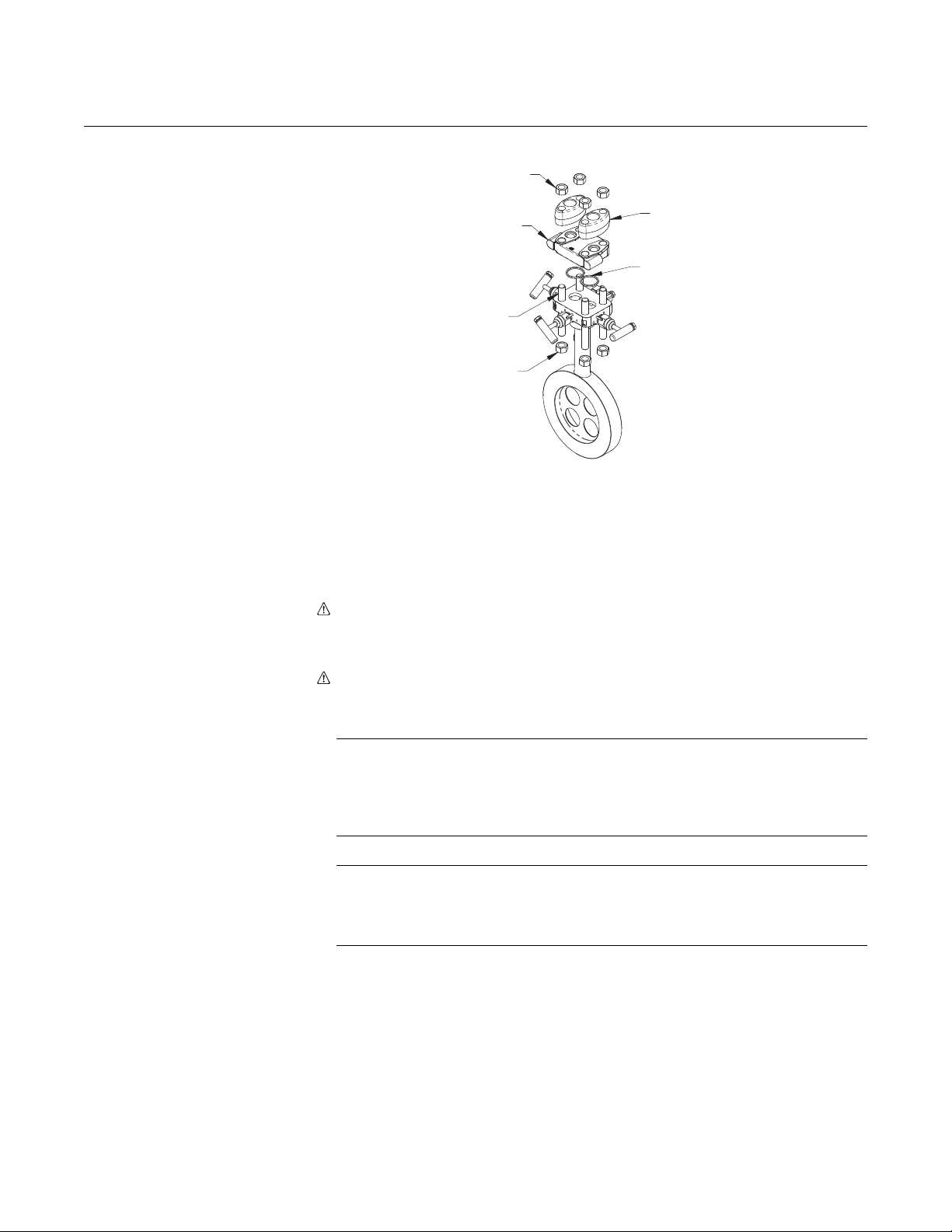
Figure 2-9. Installing the Flange
Adapters to a 405
NUT
FLANGE
DAPTER
PLATE
STUD
NUT
ADAPTER
O-RING
When compressed, PTFE o-rings tend to cold flow, which aids in their sealing
capabilities. When removing adapter plates or adapters, visually inspect the
o-rings. Replace them if there are any signs of damage, such as nicks or cuts.
If they are undamaged, you may reuse them. If you replace the o-rings,
retorque the nuts after installation to compensate for cold flow.
High Temperature Units (Option Code T)
®
Inconel
o-rings should be replaced any time the unit is disassembled.
INSTALLATION Install the 405 according to the procedure below.
1. Orient the assembly according to the guidelines provided in "Location
and Orientation" beginning on page 2-4. Ensure that the flow arrow is
pointing in the same direction as the process flow.
NOTE
An ANSI alignment ring is provided standard with the 405. If a DIN or JIS
alignment ring is required, it must be ordered as an option. Contact an
Emerson Process Management sales representative for additional
information.
NOTE
For ease of installation, the gasket may be secured to the flange face with
small pieces of tape. Be sure the gasket and/or tape do not protrude into the
pipe.
2. If using an alignment ring with through holes, proceed to step 9.
3. Insert two studs through the flange holes located opposite the head of
the 405.
2-8
Page 19

Reference Manual
00809-0100-4810, Rev DA
September 2007
Rosemount Compact Orifice
Flowmeter Series
4. Place the alignment ring on the 405 body (see Figure 2-10).
5. Insert gaskets.
6. Insert the 405 between the flanges so that the indentations on the
alignment ring contact the installed studs. The studs must contact the
alignment ring in the indentation marked with the appropriate flange
rating to ensure proper alignment.
7. Install remaining studs and nuts (hand tight). Ensure that three of the
studs are in contact with the alignment ring.
8. Lubricate studs and tighten nuts in a cross pattern to the appropriate
torque per local standards.
Steps 9-12 are for use with alignment rings that have through holes.
9. Place the alignment ring on the 405 body (see Figure 2-10).
10. Insert the 405 between the flanges. Insert one stud through the
flange hole located opposite the 405 head; passing through the
alignment ring through hole and the opposite flange hole. The stud
must contact the alignment ring through the through hole marked with
the appropriate flange rating to ensure proper alignment.
11. Repeat step 10 for a second (2) stud opposite the 405 head.
12. Insert gaskets.
13. Install remaining studs and nuts (hand tight). Ensure that three of the
studs are in contact with the alignment ring.
14. Lubricate studs and tighten nuts in a cross pattern to the appropriate
torque per local standards.
NOTE
Standard
gaskets could potentially caused a bias shift in the measurement.
1
/16-in. gaskets are recommended for use with the 405. Using other
2-9
Page 20

Rosemount Compact Orifice
ALIGNMENT RING
405
(1)
ALIGNMENT RING
(2)
TRANSMITTER
(2) GASKET
ASSEMBLY
WITH FLANGE
NUT
STUD
EXISTING PIPE
405
(1)
(1) This installation drawing applies to both the 405P and 405C.
(2) Applies to both the 3051SFC (uses a 3051S transmitter) and a 3095MFC (uses a 3095M transmitter).
Flowmeter Series
Figure 2-10. 405 Installation
Reference Manual
00809-0100-4810, Rev DA
September 2007
Remote RTD Installation A remote RTD requires that the process piping be modified. Follow site
specific requirements for installation. Install the RTD thermowell in close
proximity downstream
connection cable is 12 ft long. Consult factory for longer lengths.
5
Drill a
/8-in. (16 mm) to 3/4-in. (19 mm) hole at the RTD location and weld on a
customer supplied 1-in. (25mm) tall
thermowell threads into the weld coupling. The thermowell material is 316
1
SST with
/2–14 ANPT threads. When installed It will be inserted 11/2-in. (38
mm) into the pipe internal diameter.
For remote RTD applications with pipe diameters less than 2 inches (50mm)
consult factory.
(1)
of the primary element. The standard supplied RTD
1
/2 inch -14 NPT weld coupling. The RTD
2-10
(1) For the 405P, at least six pipe diameters downstream of the primary element. For the 405C,
two pipe diameters downstream of the primary element.
Page 21

Reference Manual
00809-0100-4810, Rev DA
September 2007
Rosemount Compact Orifice
Flowmeter Series
Section 3 Commissioning
Safety Messages . . . . . . . . . . . . . . . . . . . . . . . . . . . . . . . . . page 3-1
Direct Mount Applications . . . . . . . . . . . . . . . . . . . . . . . . . page 3-2
Remote Mount Applications . . . . . . . . . . . . . . . . . . . . . . . page 3-5
SAFETY MESSAGES Instructions and procedures in this section may require special precautions to
ensure the safety of the personnel performing the operations. Please refer to
the following safety messages before performing any operation in this section.
Explosions could result in death or serious injury:
• Do not remove the transmitter cover in explosive atmospheres when the circuit is
live.
• Before connecting a HART Communicator in an explosive atmosphere, make sure
the instruments in the loop are installed in accordance with intrinsically safe or
non-incendive field wiring practices.
• Verify that the operating atmosphere of the transmitter is consistent with the
appropriate hazardous locations certifications.
• Both transmitter covers must be fully engaged to meet explosion-proof
requirements.
Failure to follow these installation guidelines could result in death or serious injury:
• Make sure only qualified personnel perform the installation.
• If the line is pressurized, serious injury or death could occur by opening valves.
3-1
Page 22
Rosemount Compact Orifice
LOW VALVE
HIGH VALVE
EQUALIZER
VALVE
(2) VENT
FLOW
Flowmeter Series
DIRECT MOUNT
APPLICATIONS
Liquid Service 1. Pressurize line.
2. Open the equalizer valve.
3. Open the high and low side valves.
4. Bleed drain/vent valves until no gas is apparent in the liquid.
5. Close the vent/drain valves.
6. Close the low side valve.
7. Check the transmitter zero according to the transmitter product
manual so that the output on the test meter reads zero percent of
span.
8. Close the equalizer valve.
9. Open the low side valve. The system is now operational.
Figure 3-1. Direct Mount Liquid
Service
Reference Manual
00809-0100-4810, Rev DA
September 2007
3-2
Page 23
Reference Manual
LOW VALVE
HIGH VALVE
VALVE
EQUALIZER
(2) VENT
FLOW
00809-0100-4810, Rev DA
September 2007
Gas Service 1. Pressurize line.
2. Open the equalizer valve.
3. Open the high and low side valves.
4. Open drain/vent valves to ensure no liquid is present.
5. Close the vent/drain valves.
6. Close the low side valve.
7. Check the transmitter zero according to the transmitter product
manual so that the output on the test meter reads zero percent of
span.
8. Close the equalizer valve.
9. Open the low side valve. The system is now operational.
Figure 3-2. Direct Mount Gas
Service
Rosemount Compact Orifice
Flowmeter Series
3-3
Page 24
Rosemount Compact Orifice
LOW VALVE
HIGH VALVE
EQUALIZER
VALVE
(2) VENT
FLOW
Flowmeter Series
Steam Service 1. Remove pressure from line.
2. Open equalizer, high, and low side valves.
3. Zero electronics.
4. Fill manifold and transmitter with water via drain vents.
5. Close low side valve.
6. Pressurize line.
7. Gently tap electronics body, manifold head, and 405 body with a
small wrench to dislodge any entrapped air.
8. Zero electronics.
9. The system is now operational.
Figure 3-3. Direct Mount
Steam Service
Reference Manual
00809-0100-4810, Rev DA
September 2007
3-4
Page 25
Reference Manual
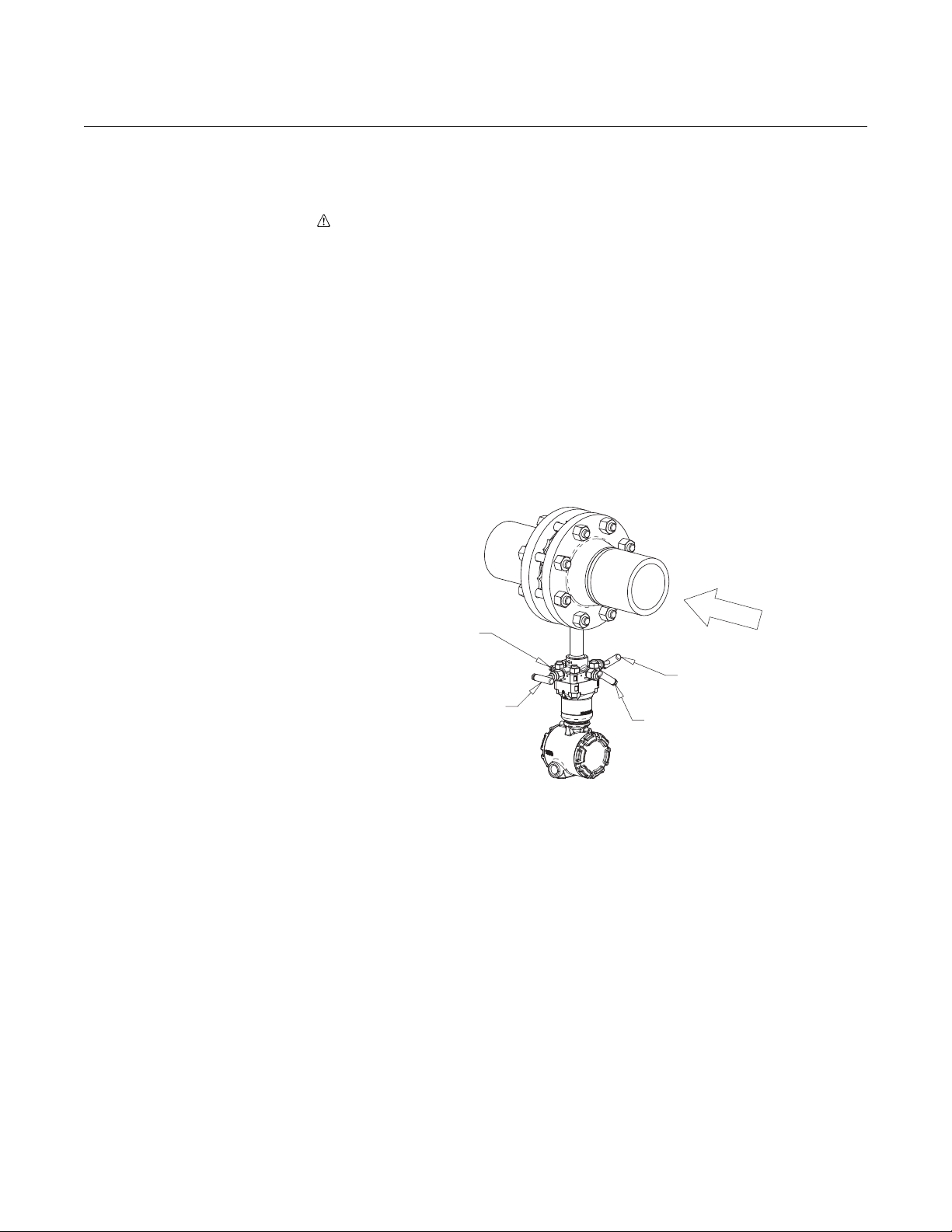
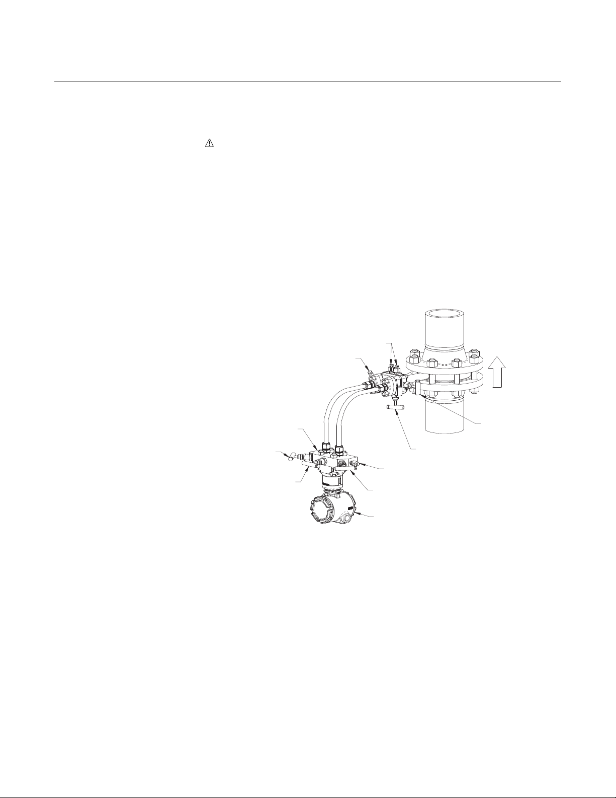
MANIFOLD
VENT
MANIFOLD
LOW
VALVE
TRANSMITTER
MANIFOLD
TRANSMITTER
405 HIGH VALVE
405 EQUALIZER VALVE
405 LOW VALVE
VENTS
MANIFOLD
HIGH
VALVE
MANIFOLD
EQUALIZER
VALVE
FLOW
Rosemount Compact Orifice
00809-0100-4810, Rev DA
September 2007
REMOTE MOUNT
APPLICATIONS
Liquid Service 1. Zero electronics and pressurize line.
2. Open equalizer valves on transmitter manifold and 405.
3. Open high and low side transmitter manifold valves and 405 valves.
4. Bleed drain vent valves on transmitter manifold until no air is present.
5. Close drain vent valves.
6. Close equalizer valve on 405.
7. Check transmitter zero. If transmitter does not read zero repeat steps
1-7.
8. Close equalizer valve on transmitter manifold.
Figure 3-4. Remote Liquid
Service
Flowmeter Series
3-5
Page 26

Rosemount Compact Orifice
R
Flowmeter Series
Gas Service 1. Zero electronics and pressurize line.
2. Open equalizer valves on transmitter manifold and 405.
3. Open high and low side transmitter manifold valves and 405 valves.
4. Open drain/vent valves on transmitter manifold to ensure no liquids
are present.
5. Close drain/vent valves.
6. Close low side transmitter manifold valve.
7. Close 405 equalizer valve.
8. Check transmitter zero. If transmitter does not read zero repeat steps
1-7.
9. Close equalizer on transmitter manifold.
10. Open low side valve on transmitter manifold. The system is now
operational.
Figure 3-5. Remote Gas Service
MANIFOLD
VENT
405 LOW VALVE
405 EQUALIZER VALVE
Reference Manual
00809-0100-4810, Rev DA
September 2007
TRANSMITTER
TRANSMITTE
MANIFOLD
MANIFOLD
LOW
VALVE
FLOW
405 HIGH VALVE
VENTS
MANIFOLD
EQUALIZER
VALVE
MANIFOLD
HIGH
VALVE
3-6
Page 27

Reference Manual
MANIFOLD
VENT
MANIFOLD
LOW
VALVE
TRANSMITTER
MANIFOLD
TRANSMITTER
405 HIGH VALVE
405 EQUALIZER VALVE
405 LOW VALVE
VENTS
MANIFOLD
HIGH
VALVE
MANIFOLD
EQUALIZER
VALVE
FLOW
Rosemount Compact Orifice
00809-0100-4810, Rev DA
September 2007
Steam Service 1. Remove pressure from line.
2. Open equalizer valves, high side valves, and low side valves on both
the 405 and transmitter manifold.
3. Zero electronics.
4. Fill transmitter manifold, instrument lines, and 405 with water via
drain vents on transmitter manifold.
5. Close 405 equalizer valve and transmitter manifold vents.
6. Close low side transmitter manifold valve.
7. Pressurize line.
8. Gently tap electronics body, transmitter manifold, instrument lines,
and 405 with a small wrench to dislodge any trapped air.
9. Check transmitter zero. If transmitter does not read zero repeat steps
4-8.
10. Close the transmitter equalizer and open low side valve on
transmitter manifold. The system is now operational.
Flowmeter Series
Figure 3-6. Remote Steam
Service
3-7
Page 28

Rosemount Compact Orifice
Flowmeter Series
Reference Manual
00809-0100-4810, Rev DA
September 2007
3-8
Page 29

Reference Manual
00809-0100-4810, Rev DA
September 2007
Rosemount Compact Orifice
Flowmeter Series
Section 4 Operation and Maintenance
Safety Messages . . . . . . . . . . . . . . . . . . . . . . . . . . . . . . . . . page 4-1
Troubleshooting . . . . . . . . . . . . . . . . . . . . . . . . . . . . . . . . . page 4-1
RTD Maintenance . . . . . . . . . . . . . . . . . . . . . . . . . . . . . . . . page 4-3
SAFETY MESSAGES Procedures and instructions in this section may require special precautions to
ensure the safety of the personnel performing the operations. Information that
raises potential safety issues is indicated by a warning symbol ( ). Refer to
the following safety messages before performing an operation preceded by
this symbol.
Explosions can result in death or serious injury.
• Do not remove the instrument cover in explosive environments when the circuit is
live.
• Both transmitter covers must be fully engaged to meet
explosion-proof requirements.
• Before connecting a communicator in an explosive atmosphere, make sure the
instruments in the loop are installed in accordance with intrinsically safe or
nonincendive field wiring practices.
Electrical shock can result in death or serious injury.
• Avoid contact with the leads and the terminals.
TROUBLESHOOTING If a malfunction is suspected despite the absence of a diagnostic messages
on the communicator display, follow the procedures described below to verify
that the flowmeter hardware and process connections are in good working
order. Always approach the most likely and easiest-to-check conditions first.
4-1
Page 30

Rosemount Compact Orifice
Reference Manual
00809-0100-4810, Rev DA
Flowmeter Series
Symptom Possible Cause Corrective Action
Questionable accuracy or
erroneous flow signal
Spiking flow signal Two-phase flow The flowmeter is a head measurement device and will not accurately
Spiking flow signal (Stream
Service)
Milliamp reading is zero
Electronics not in
communication
Milliamp reading is low or
high
No response to changes in
applied flow
Low reading/high reading
Erratic reading for pressure
variable
Improper installation
System leaks Check for leaks in instrument piping. Repair and seal all leaks.
Contamination/plugging Remove the flowmeter and check for contamination.
Closed valve Verify that both 3095MFC (PH & PL) or (MH & ML) valves are open.
Calibration Is the calibration too high or low for the flow rate?
Connections (remote mount only) Verify that the high side of the electronics is connected to the high
Entrapped air (liquid applications) Are there uneven water legs caused by air entrapment in the
3095MFC misalignment Misalignment of the flowmeter beyond 3 degrees will cause an
Operating conditions Are the operating conditions in compliance with those given at the
Improper insulation (Vertical pipes
only)
Excessive vibration
• Is the flow arrow pointed in the direction of the flow?
• Verify that the cross reservoirs are perfectly level with one another.
• Is there sufficient straight run upstream and downstream of the
flowmeter?
Verify that vent, equalizer, and line valves are properly positioned per
the “start up procedure.”
side of the flowmeter. Check the same for the low side.
instrument connections? If so, bleed air.
erroneous signal.
time the flowmeter was purchased? Check the flow calculation and
the fluid parameters for accuracy. Double-check pipe inside diameter
for proper sizing.
measure a two-phase flow.
Added insulation may be required to ensure that a phase change
occurs at the cross reservoirs.
Check the impulse piping for vibration.
• Check if power polarity is reversed
• Verify voltage across terminals (should be 10–55V dc)
• Check for bad diode in terminal block
• Replace electronics terminal block
• Check power supply voltage at electronics (10.5V minimum)
• Check load resistance (250 ohms minimum)
• Check if unit is addressed properly
• Replace electronics board
• Check pressure variable reading for saturation
• Check if output is in alarm condition
• Perform 4–20 mA output trim
• Replace electronics board
• Check test equipment
• Check impulse piping for blockage
• Check for disabled span adjustment
• Check electronics security switch
• Verify calibration settings (4 and 20 mA points)
• Contact factory for replacement
• Check impulse piping for blockage
• Check test equipment
• Perform full sensor trim (if software revision is 35 or higher)
• Contact factory for replacement
• Check impulse piping for blockage
• Check damping
• Check for EMF interference
• Contact factory for replacement
September 2007
4-2
Page 31

Reference Manual
00809-0100-4810, Rev DA
September 2007
Rosemount Compact Orifice
Flowmeter Series
Check Flow Direction
Check that the flow arrow on the neck of the 405 points in the direction of flow.
If the DP transmitter is remote mounted from the 405, be sure that the impulse
tubing is connected correctly from the 405 to the DP transmitter (high to high
and low to low).
Check Orientation
Improper orientation can result in inaccurate measurements.
Check Zero
The transmitter may read off in the high or low direction if not zeroed properly
at start-up/commissioning. Refer to the appropriate transmitter reference
manual for additional information.
Check Valves
The correct valve setting for flow measurement are; equalizer valve fully
closed, high and low side valves fully open.
Check Configuration/Scaling
Is the 20mA DP URL of the 405 set properly? This may involve sizing the 405
in the Toolkit Software program to confirm.
Confirm the DCS or PLC and transmitter on 405 are scaled consistently.
Is the square root being taken in the DCS or transmitter attached to the 405?
The square root should not be taken in both places.
Check 3095M Configuration
If a Rosemount 3095M transmitter is being used, its enhanced functionality
should be taken into account during configuration and troubleshooting. The
square root should not be taken in the DCS if a 3095M transmitter is being
used.
See the Rosemount 3095M reference manual (document number
00809-0100-4716) for additional information.
RTD MAINTENANCE This section covers RTD maintenance procedures.
Remote Mount
If an RTD needs to be replaced on a remote mount, proceed as follows:
4-3
Page 32

Rosemount Compact Orifice
Rubber Bushing
(Slide stop to edge of armored cable)
3
/4 to 1/2–in. NPT Adapter
(Screws into RTD Connection Head)
Compression Fitting
Connect to
transmitter
Compression
Fitting
Cap
Brushing
Washer
Cap
Flowmeter Series
1. Close instrument valves to ensure that the pressure is disconnected
from the transmitter.
2. Open the bleed valves on the transmitter to remove all pressure.
3. Remove the cap.
4. Remove the RTD wiring only from the terminal.
5. Remove the Terminal Housing from the head.
6. Pull the RTD wire out of the nipple and remove the RTD. The RTD is in
a thermowell, so no live line pressure will be present.
7. Install the new RTD and thread the wires through the nipple.
8. Using the appropriate thread lubricant or tape, install the terminal
housing onto the remote head.
9. Reconnect the RTD wires to the terminal. This diagram is for a typical
RTD transmitter wiring connection.
10.Open the instrument valves.
Reference Manual
00809-0100-4810, Rev DA
September 2007
4-4
Page 33

Reference Manual
Rosemount Compact Orifice
00809-0100-4810, Rev DA
September 2007
Flowmeter Series
Appendix A Reference Data
Rosemount 3051SFC Compact Orifice Flowmeter . . . . . page A-1
Rosemount 3095MFC Compact Orifice Mass Flowmeter page A-16
Rosemount 405 Compact Orifice Primary Element . . . . . page A-28
Spare Parts . . . . . . . . . . . . . . . . . . . . . . . . . . . . . . . . . . . . . page A-37
Rosemount 3051SFC Compact Orifice Flowmeter
SPECIFICATIONS
Performance System Reference Accuracy
Percent (%) of volumetric flow rate
Table A-1. 3051SFC Compact Orifice Flowmeter
Classic
(8:1 flow
Typ e Beta
3051SFCC 0.4
3051SFCP
3051SFCP
3051SFCP
(1) Line sizes 1/2-in. (15mm)
(2) For 0.65 beta and ReD< 10,000 add an additional 0.5% to the
Discharge Coefficient Uncertainty.
0.65
(1)
0.4
0.65
(1)
0.4
0.65
(1)
0.4
0.65
turndown)
±1.05%
±1.35%
±2.45% ±2.35% ±2.30%
(2)
±2.00% ±1.90% ±1.85%
(2)
±1.55% ±1.45% ±1.40%
(2)
Ultra
(8:1 flow
turndown)
±0.85%
±1.20%
Ultra for
Flow
(14:1 flow
turndown)
±0.80%
±1.15%
Repeatability
±0.1%
Line Sizes
•1/2-in. (15 mm) – not available for the 3051SFCC
• 1-in. (25 mm) – not available or the 3051SFCC
1
/2-in. (40 mm) – not available for the 3051SFCC
•1
• 2-in. (50 mm)
• 3-in. (80 mm)
• 4-in. (100 mm)
• 6-in. (150 mm)
• 8-in. (200 mm)
Performance Statement Assumptions
• Measured pipe I.D
Sizing
Contact an Emerson Process Management representative for assistance. A Configuration Data
Sheet is required prior to order for application verification.
A-1
Page 34

Rosemount Compact Orifice
Voltage (V dc)
Load (Ohms)
Operating
Region
1387
1000
500
0
10.5 20 30
42.4
Voltage (V dc)
Load (Ohms)
Operating
Region
1322
1000
500
0
12.0 20 30
42.4
Flowmeter Series
Functional Service
•Liquid
•Gas
•Steam
4–20 mA/HART
Zero and Span Adjustment
Zero and span values can be set anywhere within the range.
Span must be greater than or equal to the minimum span.
Output
Two-wire 4–20 mA is user-selectable for linear or square root output. Digital process variable
superimposed on 4–20 mA signal, available to any host that conforms to the HART protocol.
Power Supply
External power supply required.
Standard transmitter (4–20 mA): 10.5 to 42.4 V dc with no load
3051S SIS Safety transmitter: 12 to 42 Vdc with no load
3051S HART Diagnostics transmitter: 12 to 42 Vdc with no load
Load Limitations
Maximum loop resistance is determined by the voltage level of the external power supply, as
described by:
Reference Manual
00809-0100-4810, Rev DA
September 2007
Standard Transmitter
Maximum Loop Resistance = 43.5 * (Power Supply Voltage – 10.5)
The HART communicator requires a minimum
loop resistance of 250Ω for communication.
3051S SIS Safety Transmitter (output code B)
3051S HART Diagnostics Transmitter (option code DA1)
Maximum Loop Resistance = 43.5 * (Power Supply Voltage – 12.0)
A-2
The HART communicator requires a minimum
loop resistance of 250Ω for communication.
HART Diagnostics Suite (Option Code DA1)
The 3051S HART Diagnostics Transmitter provides Abnormal Situation Prevention (ASP)
indication, device operating hours, variable logging, and enhanced EDDL graphic displays for
easy visual analysis.
Page 35

Reference Manual
00809-0100-4810, Rev DA
September 2007
Rosemount Compact Orifice
Flowmeter Series
The integral statistical process monitoring (SPM) technology calculates the mean and
standard deviation of the process variable 22 times per second and makes them available to
the user. The 3051S ASP algorithm uses these values and highly flexible configuration
options for customization to detect many user-defined or application specific abnormal
situations (e.g. plugged impulse line detection).
The device operating hours are logged along with the occurrence of diagnostic events to
enable quick troubleshooting of application and installation issues.
FOUNDATION fieldbus
Power Supply
External power supply required; transmitters operate on 9.0 to 32.0 V dc transmitter terminal
voltage.
Current Draw
17.5 mA for all configurations (including LCD display option)
F
OUNDATION fieldbus Parameters
Schedule Entries 14 (max.)
Links 30 (max.)
Virtual Communications Relationships (VCR) 20 (max.)
Standard Function Blocks
Resource Block
• Contains hardware, electronics, and diagnostic information.
Transducer Block
• Contains actual sensor measurement data including the sensor diagnostics and the ability
to trim the pressure sensor or recall factory defaults.
LCD Block
• Configures the local display.
2 Analog Input Blocks
• Processes the measurements for input into other function blocks. The output value is in
engineering or custom units and contains a status indicating measurement quality.
PID Block with Auto-tune
• Contains all logic to perform PID control in the field including cascade and feedforward.
Auto-tune capability allows for superior tuning for optimized control performance.
Backup Link Active Scheduler (LAS)
The transmitter can function as a Link Active Scheduler if the current link master device fails
or is removed from the segment.
Software Upgrade in the Field
Software for the 3051S with F
OUNDATION fieldbus Common Device Software Download procedure.
F
PlantWeb Alerts
Enable the full power of the PlantWeb digital architecture by diagnosing instrumentation
issues, communicating advisory, maintenance, and failure details, and recommending a
solution.
Advanced Control Function Block Suite
(Option Code A01)
Input Selector Block
• Selects between inputs and generates an output using specific selection strategies such as
minimum, maximum, midpoint, average, or first “good.”
Arithmetic Block
• Provides pre-defined application-based equations including flow with partial density
compensation, electronic remote seals, hydrostatic tank gauging, ratio control and others.
Signal Characterizer Block
• Characterizes or approximates any function that defines an input/output relationship by
configuring up to twenty X, Y coordinates. The block interpolates an output value for a
given input value using the curve defined by the configured coordinates.
OUNDATION fieldbus is easy to upgrade in the field using the
A-3
Page 36

Rosemount Compact Orifice
Flowmeter Series
Integrator Bock
• Compares the integrated or accumulated value from one or two variables to pre-trip and
trip limits and generates discrete output signals when the limits are reached. This block is
useful for calculating total flow, total mass, or volume over time.
Output Splitter Block
• Splits the output of one PID or other control block so that the PID will control two valves or
other actuators.
Control Selector Block
• Selects one of up to three inputs (highest, middle, or lowest) that are normally connected to
the outputs of PID or other control function blocks.
Block Execution Time
Resource Transducer LCD Block Analog Input 1, 2 20 milliseconds
PID with Auto-tune 25 milliseconds
Input Selector 20 milliseconds
Arithmetic 20 milliseconds
Signal Characterizer 20 milliseconds
Integrator 20 milliseconds
Output Splitter 20 milliseconds
Control Selector 20 milliseconds
Fully Compensated Mass Flow Block (Option Code H01)
Calculates fully compensated mass flow based on differential pressure with external process
pressure and temperature measurements over the fieldbus segment. Configuration for the
mass flow calculation is easily accomplished using the Rosemount 3095 Engineering
Assistant.
OUNDATION fieldbus Diagnostics Suite (Option Code D01)
F
3051S F
indication and enhanced EDDL graphic displays for easy visual analysis.
The integral statistical process monitoring (SPM) technology calculates the mean and
standard deviation of the process variable 22 times per second and makes them available to
the user. The 3051S ASP algorithm uses these values and highly flexible configuration
options for customization to detect many user-defined or application specific abnormal
situations (e.g. plugged impulse line detection).
OUNDATION fieldbus Diagnostics provide Abnormal Situation Prevention (ASP)
Reference Manual
00809-0100-4810, Rev DA
September 2007
A-4
Process Temperature Limits
Direct Mount Electronics
• 450 °F (232 °C)
Remote Mount Electronics
• 850 °F (454 °C) – Stainless Steel
Electronics Temperature Limits
Ambient
• –40 to 185 °F (–40 to 85 °C)
• With Integral Mount LCD Display
• With Option Code P0: –4 to 185 °F (–20 to 85 °C)
Storage
• –50 to 230 °F (–46 to 110 °C)
• With Integral Mount LCD Display: –40 to 185 °F (–40 to 85 °C)
• With Wireless Output (Code X): –40 to 185 °F (–40 to 85 °C)
(1) LCD display may not be readable and LCD updates will be slower at temperatures below -4
°F (-20 °C).
(1)
: –40 to 175 °F (–40 to 80 °C)
Page 37

Reference Manual
00809-0100-4810, Rev DA
September 2007
Rosemount Compact Orifice
Flowmeter Series
Differential Pressure Limits
Maximum differential pressure (DP) up to 800 inH2O.
Pressure Limits
Direct Mount Electronics
• Pressure retention per ANSI B16.5 600# or DIN PN
(1)
Static Pressure Limits
• Range 1A: Operates within specification between static line pressures of 0.5 psia to 2000
psig (0.03 to 138 bar)
• Ranges 2A– 3A: Operates within specifications between static line pressures of 0.5 psia and
3626 psig (0.03 bar-A to 250 bar-G)
Vibration Limits
Qualified per IEC61298-3 (1998) for field with high vibration level or pipeline with high vibration
level (10-60Hz 0.21mm displacement peak amplitude / 60 - 500Hz 3g).
The weight and length of the transmitter assembly shall not exceed 5.8 lbs and 7.75-in.
Burst Pressure Limits
Coplanar or traditional process flange
• 10000 psig (689,5 bar).
Overpressure Limits
Flowmeters withstand the following limits without damage:
• Range 1A: 2000 psig (138 bar)
• Ranges 2A–3A: 3626 psig (250 bar)
Table A-2. Overpressure Limits
Standard Type
ANSI/ASME Class 150 285 (20) 275 (19)
ANSI/ASME Class 300 740 (51) 720 (50)
ANSI/ASME Class 600 1480 (102) 1440 (99)
At 100 °F (38 °C), the rating decreases with increasing temperature.
DIN PN 10/40 580 (40) 580 (40)
DIN PN 10/16 232 (16) 232 (16)
DIN PN 25/40 580 (40) 580 (40)
At 248 °F (120 °C), the rating decreases with increasing temperature.
(1) Carbon Steel and Stainless Steel Ratings are measured in
psig (bar).
(1)
Carbon Steel
Rating
Stainless
Steel Rating
Humidity Limits
• 0–100% relative humidity
Turn-On Ti m e
Performance within specifications less than 2 seconds (typical) after power is applied to the
transmitter
Damping
Analog output response to a step input change is user-selectable from 0 to 60 seconds for one
time constant. This software damping is in addition to sensor module response time
Failure Mode Alarm
HART 4-20mA (output option codes A and B)
If self-diagnostics detect a gross transmitter failure, the analog signal will be driven offscale to
alert the user. Rosemount standard (default), NAMUR, and custom alarm levels are available
(see Table A-3).
High or low alarm signal is software-selectable or hardware-selectable via the optional switch
(option D1).
(1) Static pressure selection may effect pressure limitations.
A-5
Page 38

Rosemount Compact Orifice
T
c
T
d
Td = Dead Time
T
c
= Time Constant
Pressure Released
Response Time = Td+T
c
63.2% of Total
Step Change
Time
0%
100%
36.8%
Transmitter Output vs. Time
Flowmeter Series
Table A-3. Alarm Configuration
Default ≥ 21.75 mA ≤ 3.75 mA
NAMUR compliant
Custom levels
(1) Analog output levels are compliant with NAMUR recommendation NE 43, see option codes C4
or C5.
(2) Low alarm must be 0.1 mA less than low saturation and high alarm must be 0.1 mA greater than
high saturation.
(3) Not available with the 3051S SIS Safety Transmitter.
(2) (3)
Reference Manual
00809-0100-4810, Rev DA
September 2007
High Alarm Low Alarm
(1)
≥ 22.5 mA ≤ 3.6 mA
20.2 - 23.0 mA 3.6 - 3.8 mA
Dynamic Performance
Total Response Time (Td + Tc)
Process Variable Response Time
Dead Time (Td)
Update Rate
3051S_C, Ranges 2A - 3A:
3051S SIS, Ranges 2A - 3A:
(4)
(3)
Range 1A:
Range 1A:
3051S
3051S SIS
3051S SIS Safety Transmitter Failure Values
Safety accuracy: 2.0%
(1)
Safety response time: 1.5 seconds
(1) A 2% variation of the transmitter mA output is allowed before
a safety trip. Trip values in the DCS or safety logic solver
should be derated by 2%.
4 - 20 mA (HART®)
(1)
Fieldbus protocol
(2)
:
100 milliseconds
255 milliseconds
220 milliseconds
375 milliseconds
152 milliseconds
307 milliseconds
Not Applicable
Not Applicable
45 milliseconds (nominal) 97 milliseconds
22 times per second
11 times per second
22 times per second
Not Applicable
Typical Transmitter Response Time
A-6
(1) Dead time and update rate apply to all models and ranges; analog output only
(2) Transmitter fieldbus output only, segment macro-cycle not included.
(3) Nominal total response time at 75 °F (24 °C) reference conditions. For option code DA1, add 40 milliseconds (nominal) to 4-20 mA (HART®) total
response time values.
(4) For option code DA1, dead time (Td) is 85 milliseconds (nominal).
Page 39

Reference Manual
Rosemount Compact Orifice
00809-0100-4810, Rev DA
September 2007
Physical Temperature Measurement
Remote RTD
• 100 Ohm platinum with
housing)
Model 0078D21N00A025T32Ex
Connection Head: 00644-4410-0011
• Standard RTD cable is shielded armored cable, length is 12 feet (3.66 m)
Thermowell with Remote RTD
1
/2-in. x 1/2-in. NPT, 316 SST
•
NOTE
Remote temperature measurement is not available for
Electronic Connections for Remote Mount
1
/2–14 NPT, G1/2, and M20 × 1.5 (CM20) conduit. HART interface connections fixed to terminal
block for output code A
Material of Construction
Body/Plate
• 316 SST
• 50 micro-inch Ra surface finish
Manifold Head/Valves
• 316 SST
Flange Studs and Nuts
• Customer supplied
• Available as a spare part
Transmitter Connection Studs and Nuts
• Studs– A193 Grade B8M.
• Nuts– A194 Grade 8M.
Gasket and O-rings
• Gaskets are customer supplied.
• Durlon 8500 fiber gaskets are recommended. Consult an Emerson Process Management
representative for use with other gaskets.
• Available as a spare part
NOTE
Gaskets and O-rings must be replaced when the 405 is disassembled.
1
/2-in. NPT nipple and union (078 series with Rosemount 644
Flowmeter Series
1
/2-in., 1-in., and 11/2-in. sizes.
Transmitter Connections
Remote Mount
• Available with
Orifice Type
• Square edged
• Corner tapped
• Concentric
• Wafer-style
1
/4-in. (standard) or 1/2-in. (option code E) connections
Process Connections
Mounts between the following flange configurations:
ASME B16.5
(ANSI)
Class 150
Class 300
Class 600
ANSI alignment ring is included as standard when ordering.
DIN JIS
PN16 (option code G)
PN40 (option code H)
PN100 (option code H)
10k (option code B)
20k (option code R)
40k (option code S)
A-7
Page 40

Rosemount Compact Orifice
Flowmeter Series
Typical Orifice Hole Sizes (For 3051SFCC)
Beta is calculated by: (β) = dC / Pipe ID, where the calculated bore is equal to 2 x typical orifice
hole size (d
Table A-4. β = 0.4
Line Size 3051SFCC 3051SFCP
1
/2-in. (15 mm) Not Available 0.249 (6.325)
1-in. (25 mm) Not Available 0.420 (10.668)
1
/2-in. (40 mm) Not Available 0.644 (16.358)
1
2-in. (50 mm) 0.413 (10.490) 0.827 (21.006)
3-in. (80 mm) 0.614 (15.596) 1.227 (31.166)
4-in. (100 mm) 0.805 (20.447) 1.610 (40.894)
6-in. (150 mm) 1.213 (30.810) 2.426 (61.620)
8-in. (200 mm) 1.596 (40.538) 3.192 (81.077)
Table A-5. β = 0.65
Line Size 3051SFCC 3051SFCP
1
/2-in. (15 mm) Not Available 0.404 (10.262)
1-in. (25 mm) Not Available 0.682 (17.323)
1
1
/2-in. (40 mm) Not Available 1.047 (26.594)
2-in. (50 mm) 0.620 (15.748)
3-in. (80 mm) 0.997 (25.324) 1.994 (50.648)
4-in. (100 mm) 1.308 (33.223) 2.617 (66.472)
6-in. (150 mm) 1.971 (50.063) 3.942 (100.127)
8-in. (200 mm) 2.594 (65.888) 5.188 (131.775)
(1) Measurement is in inches (millimeters)
(2) Tolerance = ±0.002-in.
(3) Beta (β) = 0.60-in. (15.24 mm) for 2-in. line size only.
= 2d). The table below shows the diameter of each of the four typical orifice holes.
C
(1)(2)
(1)(2)
Reference Manual
00809-0100-4810, Rev DA
September 2007
(3)
1.344 (34.138)
Weight
Line Size Direct Mount (D3)
1
/2-in. (15 mm) 11.20 (5.08) 8.0 (3.63)
1-in. (25 mm) 11.70 (5.31) 8.5 (3.86)
1
1
/2-in. (40 mm) 12.45 (5.65) 9.25 (4.20)
2-in. (50 mm) 13.20 (5.99) 10.0 (4.54)
3-in. (80 mm) 13.95 (6.32) 11.75 (5.33)
4-in. (100 mm) 14.95 (6.78) 13.5 (6.12)
6-in. (150 mm) 20.45 (9.28) 17.25 (7.83)
8-in. (200 mm) 24.95 (11.32) 21.75 (9.87)
(1) Measurement in lb (kg).
(1)
Remote Mount (R3)
(1)
A-8
Page 41

Reference Manual
Upstream (inlet)
side of primary
3051SFCDP
Compact
Orifice
3051SFCDC
Conditioning
Orifice
00809-0100-4810, Rev DA
September 2007
Rosemount Compact Orifice
Flowmeter Series
Installation
Considerations
Straight Run Requirements
Table A-6. 3051SFCC Straight Pipe Requirements
Beta 0.40 0.65
Reducer (1 line size) 2 2
Single 90° bend or tee 2 2
Two or more 90 ° bends
in the same plane
Two or more 90° bends in different
plane
side of primary
Up to 10° of swirl 2 2
Upstream (inlet)
Butterfly valve (75% to 100% open) 2 N/A
Downstream (outlet) side of primary
2 2
2 2
22
Table A-7. 3051SFCP Straight Pipe Requirements
Beta 0.40 0.65
Reducer (1 line size) 5 12
Single 90° bend or tee 16 44
Two or more 90 ° bends
in the same plane
Two or more 90° bends
in different plane
Expander 12 28
Ball / Gate valve fully open 12 18
Downstream (outlet) side of primary
(1) Consult an Emerson Process Management representative if
disturbance is not listed.
(2) Recommended lengths represented in pipe diameters per ISO 5167.
(3) Refer to ISO 5167 for recommended lengths when using flow
straighteners.
10 44
50 60
6 7
(1)
(1)(2)(3)
Pipe Orientation
Pipe orientation for both 3051SFCC Compact Conditioning and standard 3051SFCP Compact
Orifice.
Process
Orientation/ Flow Direction
Horizontal D/R D/R D/R
Verti cal Up R D/R R
Vertical Down D/R NR NR
(1) D = Direct mount acceptable (recommended)
R = Remote mount acceptable
NR = Not recommended
Gas Liquid Steam
(1)
Pipe Centering
Improper centering of any orifice type device can cause an error of up to ±5% in small line sizes.
A centering mechanism (centering ring) independent of flange rating comes standard with the
405 Compact Orifice Series.
A-9
Page 42

Rosemount Compact Orifice
30°
120°
30°
360°
FLOW
Flowmeter Series
Flowmeter Orientation
Flowmeter orientation for both 3051SFC Conditioning Compact Orifice and standard Compact
Orifice.
Reference Manual
00809-0100-4810, Rev DA
September 2007
Gas (Horizontal)
Liquid and Steam (Horizontal)
50°
50°
80°
Gas (Vertical)
Liquid (Vertical)
360°
FLOW
A-10
Page 43

Reference Manual
1.0 (25.4)
C
A
B
1.0 (25.4)
C
00809-0100-4810, Rev DA
September 2007
DIMENSIONAL DRAWINGS
Rosemount 3051SFC Compact Orifice Flowmeter
Orifice Plate Front View Orifice Plate Side View Orifice Plate Top View
B
A
Compact Orifice Plate
(Primary Element Type code P)
Rosemount Compact Orifice
Flowmeter Series
D
D
(Primary Element Type code C)
Conditioning Orifice Plate
Table A-8. Dimensional Drawings
Plate Type A B Transmitter Height C D
Type P and C 5.50 (140) Transmitter Height + A 7.75 (197) 7.75 (197) - closed
(1) Measurement in inches (millimeters).
(1)
8.25 (210) - open
6.00 (152) - closed
6.25 (159) - open
A-11
Page 44

Rosemount Compact Orifice
Reference Manual
00809-0100-4810, Rev DA
Flowmeter Series
September 2007
ORDERING INFORMATION
Rosemount 3051SFC Compact Orifice Flowmeter Ordering Information
Model Product Description
3051SFC Compact Orifice Flowmeter
Code Measurement Type
D Differential Pressure
Code Primary Element Type
C Conditioning Orifice Plate
P Orifice Plate
Code Material Type
S 316 Stainless Steel (SST)
Code Line Size
(1) 1
005
(1)
010
(1)
015
020 2-in. (50 mm)
030 3-in. (80 mm)
040 4-in. (100 mm)
060 6-in. (150 mm)
080 8-in. (200 mm)
Code Primary Element Style
N Square Edged
Code Beta Ratio
040 0.40 Beta Ratio (β)
(2)
065
Code Temperature Measurement
R Remote Thermowell and RTD
0 No Temperature Sensor
Code Electronics Connection Platform
3 Direct-mount, 3-valve integral manifold, SST
7 Remote-mount, 1/4-in. NPT connections
9 Special
Code Differential Pressure Range
1 0 to 25 in H2O (0 to 62.2 mbar)
2 0 to 250 in H2O (0 to 623 mbar)
3 0 to 1000 in H2O (0 to 2.5 bar)
Code Static Pressure Range
A None
D Absolute 0 to 800 psia (0 to 55.2 bar)
E Absolute 0 to 3626 psia (0 to 250 bar)
J Gage -14.7 to 800 psig (-1 to 55.2 bar)
K Gage -14.7 to 3626 psig (-1 to 250 bar)
Code Output Protocol
A 4–20 mA with digital signal based on HART protocol
(3)
F
X Wireless
Code Electronics Housing Style Material Conduit Entry Size
01 Assemble to Rosemount 753R Web-based Monitoring Indicator
1A PlantWeb Housing Aluminum
1B PlantWeb Housing Aluminum M20 x 1.5 (CM20)
1C PlantWeb Housing Aluminum G
1J PlantWeb Housing 316L SST
1K PlantWeb Housing 316L SST M20 x 1.5 (CM20)
1L PlantWeb Housing 316L SST G1/2
/2-in. (15 mm)
1-in. (25 mm)
11/2-in. (40 mm)
0.65 Beta Ratio (β)
FOUNDATION fieldbus protocol
1
/2-14 NPT
1
/2
1
/2-14 NPT
A-12
Page 45

Reference Manual
00809-0100-4810, Rev DA
September 2007
Rosemount Compact Orifice
Flowmeter Series
Rosemount 3051SFC Compact Orifice Flowmeter Ordering Information
2A Junction Box Housing Aluminum
2B Junction Box Housing Aluminum M20 x 1.5 (CM20)
2C Junction Box Housing Aluminum G
2E Junction Box housing with output for remote display and interface Aluminum
2F Junction Box housing with output for remote display and interface Aluminum M20 x 1.5 (CM20)
2G Junction Box housing with output for remote display and interface Aluminum G1/2
2J Junction Box Housing 316L SST
2M Junction Box housing with output for remote display and interface 316L SST
5A Wireless PlantWeb housing Aluminum M20 x 1.5 (CM20)
(4)
7J
Code Electronics Performance Class for Flow
(5)
1
2 Classic: up to ± 1.05% flow rate accuracy, 8:1 flow turndown, 5-year stability
(5)
3
5 Classic 2: 0.xx% flow rate accuracy, 8:1 flow turndown, 5-year stability
Code Options
Installation Accessories
G DIN alignment ring (PN 16)
H DIN alignment ring (PN 40, PN 100)
B JIS Alignment Ring 10K
R JIS Alignment Ring 20K
S JIS Alignment Ring 40K
Remote Adapters
E Flange adapters 316 SST (1/2-in. NPT)
High Temperature Applications
T Graphite valve packing (Tmax = 850 °F)
Flow Calibration
(6)
WC
(6)
WD
Pressure Testing
P1 Hydrostatic testing with certificate
Special Cleaning
P2 Cleaning for special processes
PA Cleaning per ASTM G93 Level D (section 11.4)
Special Inspection
QC1 Visual and dimensional inspection with certificate
QC7 Inspection and performance certificate
Transmitter Calibration Certification
Q4 Calibration Data Certificate for Transmitter
Safety Certification
QS Certificate of FMEDA data
QT Safety Certified to IEC 61508 with certificate of FMEDA data
Material Traceability Certifications
Q8 Material Cert per ISO 10474 3.1.B and EN 10204 3.1.B
Code Conformance
J2 ANSI B31.1
J3 ANSI B31.3
J4 ANSI B31.8
(7)
J5
Country Certification
J1 Canadian Registration
Product Certifications
E1 ATEX Flameproof
I1 ATEX Intrinsically Safe
(8)
IA
N1 ATEX Type n
Quick Connect (A size Mini, 4-pin male termination)
Ultra: up to ± 0.85% flow rate accuracy, 8:1 flow turndown, 10-year stability, limited 12-year warranty
Ultra for Flow: up to ± 0.75% flow rate accuracy, 14:1 flow turndown, 10-year stability. limited 12-year warranty
Discharge coefficient verification (3 point)
Discharge coefficient verification (full 10 point)
NACE MR-0175 / ISO 15156
ATEX FISCO Intrinsically Safe; for FOUNDATION fieldbus protocol only
1
/2-14 NPT
1
/2
1
/2-14 NPT
1
/2-14 NPT
1
/2-14 NPT
A-13
Page 46

Rosemount Compact Orifice
Reference Manual
00809-0100-4810, Rev DA
Flowmeter Series
September 2007
Rosemount 3051SFC Compact Orifice Flowmeter Ordering Information
ND ATEX Dust
K1 ATEX Flameproof, Intrinsically Safe, Type n, Dust (combination of E1, I1, N1, and ND)
E4 TIIS Flameproof
E5 FM Explosion-proof
I5 FM Intrinsically Safe, Non-incendive
K5 FM Explosion-proof, Intrinsically Safe, Non-incendive (combination of E5 and I5)
E6 CSA Explosion-proof, Division 2
I6 CSA Intrinsically Safe
K6 CSA Explosion-proof, Intrinsically Safe, Division 2 (combination of E6 and I6)
(8)
E7
I7 IECEx Intrinsically Safe
N7 IECEx Type n
K7 SAA Flameproof, Dust Ignition-proof, IECEx Intrinsically Safe, and Type n (combination of E7, I7, and N7)
KA ATEX and CSA Flameproof, Intrinsically Safe (combination of E1, I1, E6, and I6)
KB FM and CSA Explosion-proof, Intrinsically Safe, Division 2 (combination of E5, E6, I5, and I6)
KC FM and ATEX Explosion-proof, Intrinsically Safe, Non-incendive (combination of E5, E1, I5, and I1)
KD FM, CSA, and ATEX Explosion-proof, Intrinsically Safe (combination of E5, I5, E6, I6, E1, and I1)
Alternative Transmitter Material of Construction
L1 Inert Sensor Fill Fluid (not available with Differential Pressure range code 1A)
L2 Graphite-filled Teflon® (PTFE) o-ring
LA Inert sensor fill fluid and graphite-filled Teflon (PTFE) o-ring
Display
M5 PlantWeb LCD display
(5)(10)
M8
(5)(10)
M9
Terminal Blocks
(9)
T1
(11)
T2
(11)
T3
Manifold for Remote Mount Option
F2 3-Valve Manifold, SST
F6 5-Valve Manifold, SST
PlantWeb Control Functionality
(12)
A01
PlantWeb Diagnostic Functionality
(12)
D01
(13)
DA1
Wireless Transmit Rate, Operating Frequency and Protocol
WA1 HART, Self Organizing Network - 2.4 GHz
WA2 User Configurable Transmit Rate, 900 MHz FHSS, HART
Antenna and SmartPower Options
WK1 Integral, Omnidirectional Antenna, Long-life Battery Pack
Cold Temperature Procedure
BRR -60 °F (-51 °C) Temperature Soak with Power Cycle
Special Configuration (Software)
(14)
C4
(1) Not available for Primary Element Type code C.
(2) For 2-in. (50.8 mm) line sizes the Beta Ratio is 0.6 for Primary Element Type code C.
(3) Requires PlantWeb housing.
(4) Available with output code A only. Available approvals are FM Intrinsically Safe, Non-incendive (option code I5) or ATEX Instrinsically Safe (option code I1).
SAA Flameproof, Dust Ignition-proof
Note: Only available on Housing Style codes 1A, 1J, 2A, 2J, 2E, or 2M.
Note: Only available on Housing Style codes 1A, 1J, 2A, 2J, 2E, or 2M.
Note: Only available on Housing Style codes 1A, 1J, 2A, 2J, 2E, or 2M.
Note: Only available on Housing Style codes 1A, 1J, 2A, 2J, 2E, or 2M.
(9)
Remote mount LCD display and interface, PlantWeb housing, 50 foot cable, SST bracket
Remote mount LCD display and interface, PlantWeb housing, 100 foot cable, SST bracket
Transient terminal block
Terminal block with WAGO spring clamp terminals
Transient terminal block with WAGO spring clamp terminals
FOUNDATION fieldbus Advanced Control Function Block Suite
FOUNDATION fieldbus Diagnostics Suite
HART Diagnostic Suite
NAMUR alarm and saturation signal levels, high alarm
Contact an Emerson Process Management representative for additional information.
A-14
Page 47

Reference Manual
Rosemount Compact Orifice
00809-0100-4810, Rev DA
September 2007
(5) Not available with Output Protocol code B.
(6) Not available with Primary Element Type code P.
(7) Materials of Construction comply with metallurgical requirements within NACE MR0175/ISO for sour oil field production environments. Environmental limits
apply to certain materials. Consult latest standard for details. Selected materials also conform to NACE MR0103 for sour refining environments.
(8) Consult factory for availability.
(9) Not available with Housing code 7J.
(10) Not available with Output Protocol code F or option code DA1.
(11) Available with Output Protocol code A and Plantweb housing only.
(12) Requires PlantWeb housing and output code F.
(13) Requires PlantWeb housing and output code A. Includes Hardware Adjustments as standard. Contact an Emerson Process Management representative
regarding availability.
(14) Not available for Output Protocol code F.
Flowmeter Series
A-15
Page 48

Rosemount Compact Orifice
Reference Manual
00809-0100-4810, Rev DA
Flowmeter Series
September 2007
Rosemount 3095MFC Compact Orifice Mass Flowmeter
SPECIFICATIONS
Performance System Reference Accuracy
Percent (%) of mass flow rate
Table A-9. 3095MFC Compact Orifice Mass Flowmeter
Mass flow
(8:1 flow
TYPE BETA
3095MFCC 0.4 ±0.90% ±0.70%
3095MFCP
3095MFCP
3095MFCP
(1) Line sizes 1/2-in. (15mm)
(2) Line sizes 1-in. to 1 1/2-in. (25mm to 40mm)
(3) Line sizes 2-in. to 8-in. (50mm to 200mm)
(4) For 0.65 beta and ReD< 10,000 add an additional 0.5% to the
(1)
(2)
(3)
Discharge Coefficient Uncertainty.
0.65 ±1.30% ±1.15%
0.4
0.65
0.4
0.65
0.4
0.65
(4)
(4)
(4)
turndown)
±2.50% ±2.45%
±2.10% ±2.00%
±1.50% ±1.40%
Ultra for Flow
(10:1 flow
turndown)
Repeatability
±0.1%
Line Sizes
•1/2-in. (15 mm) – not available for the 3095MFCC
• 1-in. (25 mm) – not available for the 3095MFCC
1
•1
/2-in. (40 mm) – not available for the 3095MFCC
• 2-in. (50 mm)
• 3-in. (80 mm)
• 4-in. (100 mm)
• 6-in. (150 mm)
• 8-in. (200 mm)
Output
Two-wire 4–20 mA, user-selectable for DP, AP, GP, PT, mass flow, or totalized flow. Digital HART
protocol superimposed on 4–20 mA signal, available to any host that conforms to the HART
protocol.
Performance Statement Assumptions
• Measured pipe I.D.
• Electronics are trimmed for optimum flow accuracy
Sizing
Contact an Emerson Process Management representative for assistance. A Configuration Data
Sheet is required prior to order for application verification.
Functional Service
•Liquid
•Gas
•Steam
A-16
Page 49

Reference Manual
Load (Ohms)
0
11.0 42.4
(1)
55
Operating
Region
(1) For CSA approval, power supply must not exceed 42.4 V dc.
(2) HART protocol communication requires a loop resistance value
between 250-1100 ohms, inclusive.
Power Supply
250
16.5
(2)
Maximum Loop Resistance = Power Supply - 11.0
0.022
2000
00809-0100-4810, Rev DA
September 2007
Rosemount Compact Orifice
Flowmeter Series
Power Supply
4–20 mA option
• External power supply required. Standard transmitter
(4–20 mA) operates on 11 to 55 v dc with no load
Process Temperature Limits
Direct Mount Electronics
• 450 °F (232 °C)
Remote Mount Electronics
• 850 °F (454 °C) – Stainless Steel
Electronics Temperature Limits
Ambient
• -40 to 185 °F (-40 to 85 °C)
• With integral meter: -4 to 175 °F (-20 to 80 °C)
Storage
• -50 to 230 °F (-46 to 110 °C)
• With integral meter: -40 to 185 °F (-40 to 85 °C)
Differential Pressure Limits
Maximum differential pressure (DP) up to 800 inH2O.
Pressure Limits
Direct Mount Electronics
• Pressure retention per ANSI B16.5 600# or DIN PN 100
(1)
Overpressure Limits
0 to 2 times the absolute pressure range with a maximum of 3626 psia (250 bar).
Static Pressure Limits
Operates within specification between static pressures of 0.5 psia (0.03 bar-A) and the URL of
the static pressure sensor.
Vibration Limits
Qualified per IEC61298-3 (1998) for field with high vibration level or pipeline with high vibration
level (10-60Hz 0.21mm displacement peak amplitude / 60 - 500Hz 3g).
The weight and length of the transmitter assembly shall not exceed 5.8 lbs and 7.75-in.
Load Limitations
Maximum loop resistance is determined by the voltage level of the external power supply, as
described by:
(1) Static pressure selection may effect pressure limitations.
A-17
Page 50

Rosemount Compact Orifice
Flowmeter Series
FOUNDATION fieldbus (output option code V)
Power Supply
External power supply required; transmitters operate on 9.0 to 32.0 V dc transmitter terminal
voltage.
Current Draw
17.5 mA for all configurations (including LCD display option)
Humidity Limits
• 0–100% relative humidity
Turn-On Ti m e
Digital and analog measured variables will be within specification
7 – 10 seconds after power is applied to the transmitter.
Digital and analog flow output will be within specifications 10 – 14 seconds after power is applied
to the transmitter.
Damping
Analog output response to a step input change is user-selectable from 0 to 29 seconds for one
time constant. This software damping is in addition to sensor module response time
Reference Manual
00809-0100-4810, Rev DA
September 2007
Failure Mode Alarm
Output Code A
If self-diagnostics detect a non-recoverable transmitter failure, the analog signal will be driven
either below 3.75 mA or above 21.75 mA to alert the user. High or low alarm signal is
user-selectable by internal jumper pins.
Output Code V
If self-diagnostics detect a gross transmitter failure, that information gets passed as a status
along with the process variable(s).
Configuration
HART Hand-held Communicator (Model 275 or 375)
• Performs traditional transmitter maintenance functions
3095 MultiVariable Engineering Assistant (EA) software package
• Contains built-in physical property database
• Enables mass flow configuration, maintenance, and diagnostic functions via HART modem
(output option code A)
• Enables mass flow configuration via PCMCIA Interface for F
option code V)
OUNDATION fieldbus (output
Physical Properties Database
• Maintained in Engineering Assistant Software Configurator
• Physical properties for over 110 fluids
• Natural gas per AGA
• Steam and water per ASME
• Other database fluids per American Institute of Chemical Engineers (AIChE)
• Optional custom entry
A-18
FOUNDATION fieldbus Function Blocks
Standard Function Blocks
Resource Block
• Contains hardware, electronics, and diagnostic information.
Page 51

Reference Manual
00809-0100-4810, Rev DA
September 2007
Rosemount Compact Orifice
Flowmeter Series
Transducer Block
• Contains actual sensor measurement data including the sensor diagnostics and the ability
to trim the pressure sensor or recall factory defaults.
LCD Block
• Configures the local display.
5 Analog Input Blocks
• Processes the measurements for input into other function blocks. The output value is in
engineering or custom units and contains a status indicating measurement quality.
PID Block with Auto-tune
• Contains all logic to perform PID control in the field including cascade and feedforward.
Auto-tune capability allows for superior tuning for optimized control performance.
Advanced Control Function Block Suite
(Option Code A01)
Input Selector Block
• Selects between inputs and generates an output using specific selection strategies such as
minimum, maximum, midpoint, average, or first “good.”
Arithmetic Block
• Provides pre-defined application-based equations including flow with partial density
compensation, electronic remote seals, hydrostatic tank gauging, ratio control and others.
Signal Characterizer Block
• Characterizes or approximates any function that defines an input/output relationship by
configuring up to twenty X, Y coordinates. The block interpolates an output value for a
given input value using the curve defined by the configured coordinates.
Integrator Bock
• Compares the integrated or accumulated value from one or two variables to pre-trip and
trip limits and generates discrete output signals when the limits are reached. This block is
useful for calculating total flow, total mass, or volume over time.
Output Splitter Block
• Splits the output of one PID or other control block so that the PID will control two valves or
other actuators.
Control Selector Block
• Selects one of up to three inputs (highest, middle, or lowest) that are normally connected to
the outputs of PID or other control function blocks.
Physical Temperature Measurement
Remote RTD
• 100 Ohm platinum with
housing)
Model 0078D21N00A025T32Ex
Connection Head: 00644-4410-0011
• Standard RTD cable is shielded armored cable, length is 12 feet (3.66 m)
• Remote RTD material is SST
Thermowell
1
/2-in. x 1/2-in. NPT, 316 SST
•
NOTE
Remote temperature measurement is not available for
Electronic Connections for Remote Mount
•1/2–14 NPT, G1/2, and M20 × 1.5 (CM20) conduit. HART interface connections fixed to
terminal block for output code A
(1) Static pressure selection may effect pressure limitations.
1
/2-in. NPT nipple and union (078 series with Rosemount 644
(1)
1
/2-in., 1-in., and 11/2-in. sizes.
A-19
Page 52

Rosemount Compact Orifice
Flowmeter Series
Material of Construction
Body/Plate
• 316 SST
• 50 micro-inch Ra surface finish
Manifold Head/Valves
• 316 SST
Flange Studs and Nuts
• Customer supplied
• Available as a spare part
Transmitter Connection Studs and Nuts
• Studs– A193 Grade B8M.
• Nuts– A194 Grade 8M.
Gasket and O-rings
• Gaskets are customer supplied.
• Durlon 8500 fiber gaskets are recommended. Consult an Emerson Process Management
representative for use with other gaskets.
• Available as a spare part
NOTE
Gaskets and O-rings should be replaced when the 405 is disassembled.
Reference Manual
00809-0100-4810, Rev DA
September 2007
Transmitter Connections
Remote Mount
• Available with
Orifice Type
• Square edged
• Corner tapped
• Concentric
• Wafer-style
1
/4-in. (standard) or 1/2-in. (option code E) connections
Process Connections
Mounts between the following flange configurations
ASME B16.5
(ANSI)
Class 150
Class 300
Class 600
ANSI alignment ring is included as standard when ordering
DIN JIS
PN16 (option code G)
PN40 (option code H)
PN100 (option code H)
10k (option code B)
20k (option code R)
40k (option code S)
Typical Orifice Hole Sizes (For 3051MFCC)
Beta is calculated by: (β) = dC / Pipe ID, where the calculated bore is equal to 2 x typical orifice
hole size (d
Table A-10. β = 0.4
Line Size 3095MFCC 3095MFCP
1
/2-in. (15 mm) Not Available 0.249 (6.325)
1-in. (25 mm) Not Available 0.420 (10.668)
1
1
/2-in. (40 mm) Not Available 0.644 (16.358)
2-in. (50 mm) 0.413 (10.490) 0.827 (21.006)
3-in. (80 mm) 0.614 (15.596) 1.227 (31.166)
4-in. (100 mm) 0.805 (20.447) 1.610 (40.894)
6-in. (150 mm) 1.213 (30.810) 2.426 (61.620)
8-in. (200 mm) 1.596 (40.538) 3.192 (81.077)
= 2d). The table below shows the diameter of each of the four typical orifice holes.
C
(1)(2)
A-20
Page 53

Reference Manual
Upstream (inlet)
side of primary
00809-0100-4810, Rev DA
September 2007
Rosemount Compact Orifice
Flowmeter Series
Table A-11. β = 0.65
Line Size 3095MFCC 3095MFCP
1
/2-in. (15 mm) Not Available 0.404 (10.262)
1-in. (25 mm) Not Available 0.682 (17.323)
1
1
/2-in. (40 mm) Not Available 1.047 (26.594)
2-in. (50 mm) 0.620 (15.748)
3-in. (80 mm) 0.997 (25.324) 1.994 (50.648)
4-in. (100 mm) 1.308 (33.223) 2.617 (66.472)
6-in. (150 mm) 1.971 (50.063) 3.942 (100.127)
8-in. (200 mm) 2.594 (65.888) 5.188 (131.775)
(1) Measurement is in inches (millimeters)
(2) Tolerance = ±0.002-in.
(3) Beta (β) = 0.60-in. (15.24 mm) for 2-in. line size only.
(1) (2)
(3)
1.344 (34.138)
Weight
Direct Mount
Line Size (in.)
1
/2-in. (15 mm) 11.20 (5.08) 8.0 (3.63)
1-in. (25 mm) 11. 7 0 (5. 3 1) 8.5 (3.86)
1
1
/2-in. (40 mm) 12.45 (5.65) 9.25 (4.20)
2-in. (50 mm) 13.20 (5.99) 10 (4.54)
3-in. (80 mm) 13.95 (6.32) 11.75 (5.33)
4-in. (100 mm) 14.95 (6.78) 13.5 (6.12)
6-in. (150 mm) 20.45 (9.28) 17.25 (7.83)
8-in. (200 mm) 24.95 (11.32) 21.75 (9.87)
(1) Measurement in lb (kg).
(D3)
(1)
Remote Mount
(R3)
(1)
Installation
Considerations
Straight Run Requirements
Table A-12. 3095MFCC Straight Pipe Requirements
Beta 0.40 0.65
Reducer (1 line size) 2 2
Single 90° bend or tee 2 2
Two or more 90 ° bends
in the same plane
Two or more 90° bends in different
plane
side of primary
Up to 10° of swirl 2 2
Upstream (inlet)
Butterfly valve (75% to 100% open) 2 N/A
Downstream (outlet) side of primary
2 2
2 2
22
Table A-13. 3095MFCP Straight Pipe Requirements
Beta 0.40 0.65
Reducer 5 12
Single 90° bend or tee 16 44
Two or more 90 ° bends
in the same plane
Two or more 90° bends
in different plane
Expander 12 28
Ball / Gate valve fully open 12 18
Downstream (outlet) side of primary
(1) Consult an Emerson Process Management representative if
disturbance is not listed.
(2) Recommended lengths represented in pipe diameters per ISO 5167.
(3) Refer to ISO 5167 for recommended lengths when using flow
straighteners.
10 44
50 60
6 7
(1)
(1)(2)(3)
A-21
Page 54

Rosemount Compact Orifice
3095MFCDP
Compact Orifice
3095MFCDC
Conditioning Orifice
Flowmeter Series
Pipe Orientation
Pipe orientation for both 3095MFCC Compact Conditioning Mass Orifice and standard
3095MFCP Compact Mass Orifice.
Orientation/ Flow Direction
Horizontal D/R D/R D/R
Verti cal Up R D/R R
Vertical Down D/R NR NR
(1) D = Direct mount acceptable (recommended)
R = Remote mount acceptable
NR = Not recommended
Pipe Centering
Improper centering of any orifice type device can cause an error of up to ±5%
in small line sizes. A centering mechanism (centering ring) independent of
flange rating comes standard with the 405 Compact Orifice Series.
Process
Gas Liquid Steam
(1)
Reference Manual
00809-0100-4810, Rev DA
September 2007
A-22
Page 55

Reference Manual
30°
120°
30°
360°
FLOW
360°
FLOW
00809-0100-4810, Rev DA
September 2007
Rosemount Compact Orifice
Flowmeter Series
Flowmeter Orientation
Flowmeter orientation for both 3095MFC Conditioning Compact Orifice and standard Compact
Orifice.
Gas (Horizontal)
Liquid and Steam (Horizontal)
50°
50°
80°
Gas (Vertical)
Liquid (Vertical)
A-23
Page 56

Rosemount Compact Orifice
A
B
D
1.0 (25.4)
A
B
D
1.0 (25.4)
Flowmeter Series
DIMENSIONAL DRAWINGS
Rosemount 3095MFC Compact Orifice Mass Flowmeter
Orifice Plate Front View Orifice Plate Side View Orifice Plate Top View
Compact Orifice Plate
(Primary Element Type code P)
Reference Manual
00809-0100-4810, Rev DA
September 2007
C
(Primary Element Type code C)
Conditioning Orifice Plate
Table A-14. Dimensional Drawings
Plate Type A B Transmitter Height C D
Type P & C 5.50 (140) Transmitter Height + A 6.25 (159) 7.75 (197) - closed
(1) Measurement is in inches (millimeters).
(1)
8.25 (210) - open
C
6.0 (152) - closed
6.25 (159) - open
A-24
Page 57

Reference Manual
Rosemount Compact Orifice
00809-0100-4810, Rev DA
September 2007
ORDERING INFORMATION
Rosemount 3095MFC Compact Orifice Mass Flowmeter Ordering Information
Model Product Description
3095MFC Compact Orifice Mass Flowmeter
Code Primary Element Type
C Conditioning Orifice Plate
P Orifice Plate
Code Material Type
S 316 Stainless Steel (SST)
Code Line Size
(1) 1
005
(1)
010
(1)
015
020 2-in. (50 mm)
030 3-in. (80 mm)
040 4-in. (100 mm)
060 6-in. (150 mm)
080 8-in. (200 mm)
Code Primary Element Style
N Square Edged
Code Beta Ratio
040 0.40 Beta Ratio (β)
(2)
065
Code Temperature Measurement
R Remote Thermowell and RTD
0 No Temperature Sensor
Code Electronics Connection Platform
3 Direct-mount, 3-valve integral manifold, SST
7 Remote-mount, 1/4-in. NPT connections
Code Differential Pressure Range
1 0 to 25 in H2O (0 to 62.2 mbar)
2 0 to 250 in H2O (0 to 623 mbar)
3 0 to 1000 in H2O (0 to 2.5 bar)
Code Static Pressure Range
B 0 – 8 to 0 – 800 psia (0 –55.16 to 0 – 5515.8 kPa)
C 0 – 8 to 0 – 800 psig (0 –55.16 to 0 – 5515.8 kPa)
D 0 – 36.2 to 0 – 3626 psia (0 –250 to 0 – 25000 kPa)
E 0 – 36.2 to 0 – 3626 psig (0 –250 to 0 – 25000 kPa)
Code Output Protocol
A 4–20 mA with digital signal based on HART protocol
V FOUNDATION fieldbus protocol
Code Transmitter Housing Material Conduit Entry Size
1A Polyurethane-covered aluminum
1B Polyurethane-covered aluminum M20 x 1.5 (CM20)
1C Polyurethane-covered aluminum PG 13.5
1J SST
1K SST M20 x 1.5 (CM20)
1L SST PG 13.5
/2-in. (15 mm)
1-in. (25 mm)
11/2-in. (40 mm)
0.65 Beta Ratio (β)
1
/2-14 NPT
1
/2-14 NPT
Flowmeter Series
A-25
Page 58

Rosemount Compact Orifice
Flowmeter Series
Rosemount 3095MFC Compact Orifice Mass Flowmeter Ordering Information
Code Options
Performance Class
(3)
U3
PlantWeb Control Functionality
(4)
A01
Installation Accessories
G DIN alignment ring (PN 16)
H DIN alignment ring (PN 40, PN 100)
B JIS Alignment Ring 10K
R JIS Alignment Ring 20K
S JIS Alignment Ring 40K
Remote Adapters
E Flange adapters 316 SST (
High Temperature Applications
T Graphite valve packing (Tmax = 850 °F)
Flow Calibration
(5)
WC
(5)
WD
Pressure Testing
P1 Hydrostatic Testing with certificate
Special Cleaning
P2 Cleaning for special processes
PA Cleaning per ASTM G93 Level D (section 11.4)
Special Inspection
QC1 Visual and dimensional inspection with certificate
QC7 Inspection and performance certificate
Transmitter Calibration Certification
Q4 Calibration data certificate for transmitter
Material Traceability Certification
Q8 Material certification per ISO 10474 3.1.B and EN 10204 3.1.B
Code Conformance
J2 ANSI B31.1
J3 ANSI B31.3
J4 ANSI B31.8
(6)
J5
Country Certification
J1 Canadian Registration
Product Certifications
E1 ATEX Flameproof
I1 ATEX Intrinsically Safe
N1 ATEX Type n
K1 ATEX Flameproof, Intrinsically Safe, Type n, and Dust (combination of E1, I1, N1, and ND)
ND ATEX Dust
E5 FM Explosion proof
I5 FM Intrinsically Safe, non-incendive
K5 FM Explosion-proof, Intrinsically Safe, Non-Incendive
E6 CSA Explosion proof
I6 CSA Intrinsically Safe, Division 2
K6 CSA Explosion-proof, Intrinsically Safe, Division 2
(7)
IE
(6)
IF
(6)
IA
(6)
IG
Ultra for Flow: up to ±0.70% mass flow rate accuracy, up to 10:1 turndown, 10-year stability, limited 12-year warranty
Advanced Control Function Block Suite
1
/2-in. NPT)
Discharge coefficient verification (3 point)
Discharge coefficient verification (full 10 point)
NACE MR-0175 / ISO 15156
FM FISCO Intrinsically Safe; for FOUNDATION fieldbus protocol only
CSA FISCO Intrinsically Safe; for FOUNDATION fieldbus protocol only
ATEX FISCO Intrinsically Safe; for FOUNDATION fieldbus protocol only
IECEx FISCO Intrinsically Safe
Reference Manual
00809-0100-4810, Rev DA
September 2007
A-26
Page 59

Reference Manual
Rosemount Compact Orifice
00809-0100-4810, Rev DA
September 2007
Flowmeter Series
Rosemount 3095MFC Compact Orifice Mass Flowmeter Ordering Information
Alternative Transmitter Material of Construction
L1 Inert Sensor Fill Fluid
Display
M5 Integral mount LCD display
Terminal Blocks
T1 Transient Protection
Manifold for Remote Mount Option
F2 3-Valve Manifold, SST
F6 5-Valve Manifold, SST
Typical Model Number: 3051MFC C S 040 N 040 0 3 B A 1A
(1) Not available for Primary Element Type code C.
(2) For 2-in. (50.8 mm) line sizes the Beta Ratio is 0.6 for Primary Element Type code C.
(3) Ultra for Flow applicable for HART protocol, DP ranges 2 and 3 with SST isolator material and silicone fill fluid options only.
(4) Function Blocks include: Arithmetic, Integrator, Analog Output, Signal Characterizer, Control Selector, and Output Selector.
(5) Not available with Primary Element Type code P.
(6) Materials of Construction comply with metallurgical requirements within NACE MR0175/ISO 15156 for sour oil field production environments. Environmental
limits apply to certain materials. Consult latest standard for details. Selected materials also conform to NACE MR0103 for sour refining environments.
(7) Consult factory for availability.
A-27
Page 60

Rosemount Compact Orifice
Reference Manual
00809-0100-4810, Rev DA
Flowmeter Series
Rosemount 405 Compact Orifice Primary Element
SPECIFICATIONS
Performance Discharge Coefficient Uncertainty
Table A-15. 405 Compact Orifice Primary Element
Typ e Beta
405C
(Conditioning Compact)
(1)(2)
405P
(Standard Compact)
405P
(Standard Compact)
(3)
(1) Line sizes 1/2 to 11/2-in. (12.7 to 38.1 mm).
(2) Discharge Coefficient Uncertainty for
is ±2.25%.
(3) Line sizes 2 to 8-in. (50.8 to 203.2 mm)
0.4 ±0.50%
0.65 ±1.00%
0.4 ±1.75%
0.65 ±1.75%
0.4 ±1.25%
0.65 ±1.25%
Line Sizes
•1/2-in. (15 mm) – not available for the 405C
• 1-in. (25 mm) – not available for the 405C
1
/2-in. (40 mm) – not available for the 405C
•1
• 2-in. (50 mm)
• 3-in. (80 mm)
• 4-in. (100 mm)
• 6-in. (150 mm)
• 8-in. (200 mm)
Discharge Coefficient
Uncertainty
1
/2-in. units with Beta = 0.65
September 2007
Sizing
Contact an Emerson Process Management sales representative assistance. A “Configuration
Data Sheet” is required prior to order for application verification.
Functional Service
•Liquid
•Gas
• Vapor
Operating Process Temperature Limits
Standard (direct/remote mount):
• –40 to 450 °F (–40 to 232 °C)
Extended (remote mount only with option code T):
• –148 to 850 °F (–100 to 454 °C)
Differential Pressure Limits
Maximum differential pressure (DP) up to 800 inH2O.
Maximum Working Pressure
• Pressure retention per ANSI B16.5 600# or DIN PN100
Vibration Limits
Qualified per IEC61298-3 (1998) for field with high vibration level or pipeline with high vibration
level (10-60Hz 0.21mm displacement peak amplitude / 60 - 500Hz 3g).
The weight and length of the transmitter assembly shall not exceed 5.8 lbs and 7.75-in.
A-28
Page 61

Reference Manual
00809-0100-4810, Rev DA
September 2007
Assembly to a transmitter
Select option code C11 for the Rosemount 3051S transmitter (or option code S3 for the
Rosemount 3051C or 3095M transmitters) to factory assemble the Rosemount 405 to a
Rosemount pressure transmitter. If the 405 and transmitter are not factory assembled, they may
be shipped separately. For a consolidated shipment, inform the Emerson Process Management
representative when placing the order.
Physical Material of Construction
Body/Plate
• 316 SST
• 50 micro-inch Ra surface finish
Manifold Head/Valves
• 316 SST
Flange Studs and Nuts
• Customer supplied
• Available as a spare part
Transmitter Connection Studs and Nuts
• Studs– A193 Grade B8M.
• Nuts– A194 Grade 8M.
Gasket and O-rings
• Gaskets are customer supplied.
• Durlon 8500 fiber gaskets are recommended. Consult an Emerson Process Management
representative for use with other gaskets.
• Available as a spare part
NOTE
Gaskets and O-rings should be replaced when the 405 is disassembled.
Rosemount Compact Orifice
Flowmeter Series
Transmitter Connections
Direct Mount
• Integrally mount to 3051 and 3095 transmitters,
range 1, 2, and 3.
Remote Mount
• Available with
Orifice Plate Type
• Square edged
• Corner tapped
• Concentric
• Wafer-style
1
/4-in. (standard) or 1/2-in. (option code E) connections
Process Connections
Mounts between the following flange configurations:
ASME B16.5
(ANSI)
Class 150
Class 300
Class 600
ANSI alignment ring is included as standard when ordering.
DIN JIS
PN16 (option code G)
PN40 (option code H)
PN100 (option code H)
10k (option code B)
20k (option code R)
40k (option code S)
A-29
Page 62

Rosemount Compact Orifice
Flowmeter Series
Typical Orifice Hole Sizes (For 405C)
Beta is calculated by: (β) = dC / Pipe ID, where the calculated bore is equal to 2 x typical orifice
hole size (d
Table A-16. β = 0.4
Line Size 405C 405P
1
/2-in. (15 mm) Not Available 0.249 (6.325)
1-in. (25 mm) Not Available 0.420 (10.668)
1
/2-in. (40 mm) Not Available 0.644 (16.358)
1
2-in. (50 mm) 0.413 (10.490) 0.827 (21.006)
3-in. (80 mm) 0.614 (15.596) 1.227 (31.166)
4-in. (100 mm) 0.805 (20.447) 1.610 (40.894)
6-in. (150 mm) 1.213 (30.810) 2.426 (61.620)
8-in. (200 mm) 1.596 (40.538) 3.192 (81.077)
Table A-17. β = 0.65
Line Size 405C 405P
1
/2-in. (15 mm) Not Available 0.404 (10.262)
1-in. (25 mm) Not Available 0.682 (17.323)
1
/2-in. (40 mm) Not Available 1.047 (26.594)
1
2-in. (50 mm) 0.620 (15.748)
3-in. (80 mm) 0.997 (25.324) 1.994 (50.648)
4-in. (100 mm) 1.308 (33.223) 2.617 (66.472)
6-in. (150 mm) 1.971 (50.063) 3.942 (100.127)
8-in. (200 mm) 2.594 (65.888) 5.188 (131.775)
(1) Measurement is in inches (millimeters)
(2) Tolerance = ±0.002-in.
(3) Beta (β) = 0.60 (15.24 mm) for 2-in. line size only.
= 2d). The table below shows the diameter of each of the four typical orifice holes.
C
(1)(2)
(1) (2)
Reference Manual
00809-0100-4810, Rev DA
September 2007
(3)
1.344 (34.138)
Installation
Consideration
Weight
Line Size (in.) Direct Mount (D3)
1
/2-in. (15 mm) 4.0 (1.81) 8.0 (3.63)
1-in. (25 mm) 4.5 (2.04) 8.5 (3.86)
1
/2-in. (40 mm) 5.25 (2.38) 9.25 (4.20)
1
2-in. (50 mm) 6.0 (2.72) 10 (4.54)
3-in. (80 mm) 6.75 (3.06) 11.75 (5.33)
4-in. (100 mm) 7.75 (3.52) 13.5 (6.12)
6-in. (150 mm) 13.25 (6.01) 17.25 (7.82)
8-in. (200 mm) 17.75 (8.05) 21.75 (9.87)
(1) Measurement in lb (kg).
(1)
Remote Mount (R3)
(1)
Straight Pipe Requirement
Use the appropriate lengths of straight pipe upstream and downstream of the 405 to minimize the
effects of moderate flow disturbances in the pipe. Table A-18 and Table A-19 lists recommended
lengths of straight pipe per ISO 5167.
Table A-18. 405C Straight Pipe Requirements
Beta 0.40 0.65
Reducer (1 line size) 2 2
Single 90° bend or tee 2 2
Two or more 90 ° bends in the same plane 2 2
Two or more 90° bends in different plane 2 2
Up to 10° of swirl 2 2
side of primary
Upstream (inlet)
Butterfly valve (75% to 100% open) 2 N/A
Downstream (outlet) side of primary
(1)
2 2
A-30
Page 63

Reference Manual
Upstream (inlet)
side of primary
405C Conditioning
Orifice
405P Compact
Orifice
00809-0100-4810, Rev DA
September 2007
Rosemount Compact Orifice
Flowmeter Series
Table A-19. 405P Straight Pipe Requirements
Beta 0.40 0.65
Reducer 5 12
Single 90° bend or tee 16 44
Two or more 90 ° bends in the same plane 10 44
Two or more 90° bends in different plane 50 60
Expander 12 28
Ball / Gate valve fully open 12 18
Downstream (outlet) side of primary
(1) Consult an Emerson Process Management representative if disturbance is not listed.
(2) Recommended lengths represented in pipe diameters per ISO 5167.
(3) Refer to ISO 5167 for recommended lengths when using flow straighteners.
(1)(2)(3)
6 7
Pipe Orientation
Process
Orientation/ Flow Direction
Horizontal D/R D/R D/R
Verti cal Up R D/R R
Vertical Down D/R NR NR
(1) D = Direct mount acceptable (recommended)
R = Remote mount acceptable
NR = Not recommended
Gas Liquid Steam
(1)
Pipe Centering
Improper centering of any orifice type device can cause an error of up to ±5% in small line sizes.
A centering mechanism (centering ring) independent of flange rating comes standard with the
405 Compact Orifice Series.
A-31
Page 64

Rosemount Compact Orifice
30°
120°
30°
360°
FLOW
Flowmeter Series
Flowmeter Orientation
Flowmeter orientation for the Conditioning Compact Orifice and standard Compact Orifice.
Reference Manual
00809-0100-4810, Rev DA
September 2007
Gas (Horizontal)
Liquid and Steam (Horizontal)
50°
50°
80°
Gas (Vertical)
Liquid (Vertical)
360°
FLOW
A-32
Page 65

Reference Manual
VALVE
EQUALIZER
1/4"-in NPT
INSTRUMENT
INSTRUMENT
HIGH
VALVE
VALVE
LOW
ADAPTER
PLATE
.85 (21.6)
(54.1)
2.13
1.0 (25.4)
EQUALIZER
INSTRUMENT
HIGH
1/4"-in NPT
VALVE
VALVE
VALVE
INSTRUMENT
LOW
ADAPTER
PLATE
(54.1)
.85 (21.6)
2.13
1.0 (25.4)
VALVE
ADAPTER
INSTRUMENT
EQUALIZER
VALVE
PLATE
INSTRUMENT
VALVE
1/2"-in NPT
HIGH
LOW
FLANGE
ADAPTER
1.0 (25.4)
.85 (21.6)
2.13
(54.1)
00809-0100-4810, Rev DA
September 2007
DIMENSIONAL DRAWINGS
Rosemount 405 Compact Orifice Plate
Adapter Plate (R3) Flange Adapter (R3 with option E)
Rosemount Compact Orifice
(Attach to Transmitter)
1/2"-in NPT
Flowmeter Series
2.13
(54.1)
Compact Orifice Plate
(Primary Element Type code P)
HIGH
INSTRUMENT
VALVE
ADAPTER
PLATE
EQUALIZER
VALVE
FLANGE
ADAPTER
.85 (21.6)
1.0 (25.4)
LOW
INSTRUMENT
VALVE
(Primary Element Type code C)
Conditioning Orifice Plate
A-33
Page 66

Rosemount Compact Orifice
HIGH
EQUALIZER
VALVE
VALVE
INSTRUMENT
LOW
INSTRUMENT
VALVE
1.30
1.0 (25.4)
(33)
2.13
(54.1)
Flowmeter Series
Rosemount 405 Compact Orifice Plate
Front View (transmitter connection A3) Front View (transmitter connection D3)
HIGH
INSTRUMENT
VALVE
ADAPTER
PLATE
EQUALIZER
VALVE
2.13
(54.1)
.70
(18)
LOW
INSTRUMENT
VALVE
Reference Manual
00809-0100-4810, Rev DA
September 2007
(Direct Mount)
Compact Orifice Plate
(Primary Element Type code P)
(Primary Element Type code C)
Conditioning Orifice Plate
1.0 (25.4)
1.30
HIGH
INSTRUMENT
VALVE
EQUALIZER
VALVE
(33)
LOW
INSTRUMENT
VALVE
1.0 (25.4)
2.13
(54.1)
NOTE
Transmitter connection code A3 is to be used with a traditional style
transmitter (such as a Rosemount 1151). This is a stainless steel adapter
plate for allowing the direct mount of traditional style transmitters.
A-34
Page 67

Reference Manual
Rosemount Compact Orifice
00809-0100-4810, Rev DA
September 2007
ORDERING INFORMATION
Rosemount 405 Compact Orifice Primary Element Ordering Information
Model Product Description
405 Compact Primary Element
Code Primary Element Type
C Conditioning Orifice Plate
P Orifice Plate
Code Material Type
S 316 Stainless Steel (SST)
Code Line Size
(1) 1
005
(1)
010
(1)
015
020 2-in. (50 mm)
030 3-in. (80 mm)
040 4-in. (100 mm)
060 6-in. (150 mm)
080 8-in. (200 mm)
Code Primary Element Style
N Square Edged
Code Beta Ratio
040 0.40 Beta Ratio (β)
(2)
065
Code Transmitter Connection
D3 Coplanar, Direct mount, 3-valve integral manifold, SST
R3 Remote-mount, 1/4-in. NPT connections
A3 Traditional, Direct mount, 3-valve integral manifold with adapter plate, SST
Code Options
Installation Accessories
G DIN alignment ring (PN 16)
H DIN alignment ring (PN 40, PN 100)
B JIS Alignment Ring 10K
R JIS Alignment Ring 20K
S JIS Alignment Ring 40K
Adapters
E Flange adapters 316 SST (
High Temperature Applications
T Graphite valve packing (Tmax = 850 °F)
Flow Calibration
(3)
WC
(3)
WD
Pressure Testing
P1 Hydrostatic testing with certificate
Special Cleaning
P2 Cleaning for special processes
PA Cleaning per ASTM G93 Level D (section 11.4)
Continued on Next Page
/2-in. (15 mm)
1-in. (25 mm)
11/2-in. (40 mm)
0.65 Beta Ratio (β)
1
/2-in. NPT)
Discharge coefficient verification (3 point)
Discharge coefficient verification (full 10 point)
Flowmeter Series
A-35
Page 68

Rosemount Compact Orifice
Reference Manual
00809-0100-4810, Rev DA
Flowmeter Series
September 2007
Rosemount 405 Compact Orifice Primary Element Ordering Information
Special Inspection
QC1 Visual and Dimensional Inspection with certification
QC7 Inspection and performance certification
Material Traceability Certification
Q8 Material certification per ISO 10474 3.1.B and EN 10204 3.1.B
Code Conformance
J2 ANSI B31.1
J3 ANSI B31.3
J4 ANSI B31.8
(4)
J5
Country Certification
J1 Canadian Registration
Typical Model Number: 405 C S 040 N 040 D3
(1) Not available for Primary Element Type code C.
(2) For 2-in. (50.8 mm) line sizes the Beta Ratio is 0.6 for Primary Element Type code C.
(3) Not available with Primary Element Type code P.
(4) Materials of Construction comply with metallurgical requirements within NACE MR0175/ISO for sour oil field production environments. Environmental limits
NACE MR-0175 / 15156
apply to certain materials. Consult latest standard for details. Selected materials also conform to NACE MR0103 for sour refining environments.
A-36
Page 69

Reference Manual
Rosemount Compact Orifice
00809-0100-4810, Rev DA
September 2007
Flowmeter Series
SPARE PARTS
Mounting Stud and Nut Kits Gasket Kits
Part Number Part Description Part Number Part Description
08951-0100-0101
08951-0100-0102 1-in. 150# Mounting Kit 08951-0200-0102 1-in. 150# Gasket Kit
08951-0100-0103 1
08951-0100-0104 2-in. 150# Mounting Kit 08951-0200-0104 2-in. 150# Gasket Kit
08951-0100-0105 3-in. 150# Mounting Kit 08951-0200-0105 3-in. 150# Gasket Kit
08951-0100-0106 4-in. 150# Mounting Kit 08951-0200-0106 4-in. 150# Gasket Kit
08951-0100-0107 6-in. 150# Mounting Kit 08951-0200-0107 6-in. 150# Gasket Kit
08951-0100-0108 8-in. 150# Mounting Kit 08951-0200-0108 8-in. 150# Gasket Kit
08951-0100-0201
08951-0100-0202 1-in. 300# Mounting Kit 08951-0200-0202 1-in. 150# Gasket Kit
08951-0100-0203 1
08951-0100-0204 2-in. 300# Mounting Kit 08951-0200-0204 2-in. 150# Gasket Kit
08951-0100-0205 3-in. 300# Mounting Kit 08951-0200-0205 3-in. 150# Gasket Kit
08951-0100-0206 4-in. 300# Mounting Kit 08951-0200-0206 4-in. 150# Gasket Kit
08951-0100-0207 6-in. 300# Mounting Kit 08951-0200-0207 6-in. 150# Gasket Kit
08951-0100-0208 8-in. 300# Mounting Kit 08951-0200-0208 8-in. 150# Gasket Kit
08951-0100-0301
08951-0100-0302 1-in. 600# Mounting Kit 08951-0200-0302 1-in. 150# Gasket Kit
08951-0100-0303 1
08951-0100-0304 2-in. 600# Mounting Kit 08951-0200-0304 2-in. 150# Gasket Kit
08951-0100-0305 3-in. 600# Mounting Kit 08951-0200-0305 3-in. 150# Gasket Kit
08951-0100-0306 4-in. 600# Mounting Kit 08951-0200-0306 4-in. 150# Gasket Kit
08951-0100-0307 6-in. 600# Mounting Kit 08951-0200-0307 6-in. 150# Gasket Kit
08951-0100-0308 8-in. 600# Mounting Kit 08951-0200-0308 8-in. 150# Gasket Kit
1
/2-in. 150# Mounting Kit 08951-0200-0101
1
/2-in. 150# Mounting Kit 08951-0200-0103 11/2-in. 150# Gasket Kit
1
/2-in. 300# Mounting Kit 08951-0200-0201
1
/2-in. 300# Mounting Kit 08951-0200-0203 11/2-in. 150# Gasket Kit
1
/2-in. 600# Mounting Kit 08951-0200-0301
1
/2-in. 600# Mounting Kit 08951-0200-0303 11/2-in. 150# Gasket Kit
1
/2-in. 150# Gasket Kit
1
/2-in. 150# Gasket Kit
1
/2-in. 150# Gasket Kit
Remote Mount Retrofit Kits
Part Number Part Description
08951-0300-0001 Remote Retrofit Kit, 1/4-in. NPT
1
08951-0300-0002 Remote Retrofit Kit,
/2-in. NPT
A-37
Page 70

Rosemount Compact Orifice
Flowmeter Series
Miscellaneous
Part Number Part Description
08951-0400-0001 Drain / Vent Replacement Kit
08951-0401-0001 Valve Bonnet, SST
08951-0402-0001 Spare
08951-0402-0002 Spare 1-in. Alignment Ring
08951-0402-0003 Spare 1
08951-0402-0004 Spare 2-in. Alignment Ring
08951-0402-0005 Spare 3-in. Alignment Ring
08951--0402-0006 Spare 4-in. Alignment Ring
08951--0402-0007 Spare 6-in. Alignment Ring
08951--0402-0008 Spare 8-in. Alignment Ring
08951--0402-0009 Spare
08951--0402-0010 Spare 1-in. Alignment Ring
08951--0402-0011 Spare 1
08951--0402-0012 Spare 2-in. Alignment Ring
08951--0402-0013 Spare 3-in. Alignment Ring
08951--0402-0014 Spare 4-in. Alignment Ring
08951--0402-0015 Spare 6-in. Alignment Ring
08951--0402-0016 Spare 6-in. Alignment Ring
08951--0402-0017 Spare 8-in. Alignment Ring
08951--0402-0018 Spare 8-in. Alignment Ring
08951--0402-0019 Spare
08951--0402-0020 Spare 1-in. Alignment Ring
08951--0402-0021 Spare 1
08951--0402-0022 Spare 2-in. Alignment Ring
08951--0402-0023 Spare 3-in. Alignment Ring
08951--0402-0024 Spare 3-in. Alignment Ring
08951--0402-0025 Spare 4-in. Alignment Ring
08951--0402-0026 Spare 4-in. Alignment Ring
08951--0402-0027 Spare 6-in. Alignment Ring
08951--0402-0028 Spare 6-in. Alignment Ring
08951--0402-0029 Spare 8-in. Alignment Ring
1
/2-in. Alignment Ring
1
/2-in. Alignment Ring
1
/2-in. Alignment Ring
DN 15 (PN16/PN40/PN100)
DN 25 (PN16/PN40/PN100)
1
DN 40 (PN16/PN40/PN100)
DN 50 (PN16/PN40/PN100)
DN 80 (PN16/PN40/PN100)
DN 100 (PN16/PN40/PN100)
DN 150 (PN16)
DN 150 (PN16/PN40/PN100)
DN 200 (PN16)
DN 200 (PN16/PN40/PN100)
JIS DN15 (10K/20K/40K)
JIS DN25 (10K/20K/40K)
JIS DN40 (10K/20K/40K)
JIS DN50 (10K/20K/40K)
JIS DN80 (10K)
JIS DN80 (20K/40K)
JIS DN100 (10K/20K)
JIS DN100 (40K)
JIS DN150 (10K)
JIS DN150 (20K/40K)
JIS DN200 (10K/20K/40K)
/2-in. Alignment Ring
1
/2-in. Alignment Ring
1
/2-in. Alignment Ring
Reference Manual
00809-0100-4810, Rev DA
September 2007
A-38
Page 71

Reference Manual
00809-0100-4810, Rev DA
September 2007
Rosemount Compact Orifice
Flowmeter Series
Appendix B Product Certifications
3051SFC Product Certifications . . . . . . . . . . . . . . . . . . . . page B-1
3095MFC Product Certifications . . . . . . . . . . . . . . . . . . . . page B-6
Installation Drawings . . . . . . . . . . . . . . . . . . . . . . . . . . . . . page B-9
3051SFC PRODUCT
CERTIFICATIONS
Approved Manufacturing
Locations
European Directive
Information
Rosemount Inc. — Chanhassen, Minnesota USA
Emerson Process Management GmbH & Co. — Wessling, Germany
Emerson Process Management Asia Pacific Private Limited — Singapore
Beijing Rosemount Far East Instrument Co., LTD — Beijing, China
The EC declaration of conformity for all applicable European directives for this
product can be found at www.rosemount.com. A hard copy may be obtained
by contacting an Emerson Process Management representative.
ATEX Directive (94/9/EC)
Emerson Process Management complies with the
ATEX Directive.
European Pressure Equipment Directive (PED) (97/23/EC)
Models 3051S_CA4; 3051S_CD2, 3, 4, 5; (also with P9 option) Pressure
Transmitters — QS Certificate of Assessment -
EC No. PED-H-20, Module H Conformity Assessment
All other Model 3051S Pressure Transmitters
— Sound Engineering Practice
Transmitter Attachments: Diaphragm Seal - Process Flange - Manifold
Sound Engineering Practice
—
www.rosemount.com
Primary Elements, Flowmeter
— See appropriate Primary Element QIG
Electro Magnetic Compatibility (EMC) (89/336/EEC)
All Models: EN 50081-1: 1992; EN 50082-2:1995;
EN 61326-1:1997 – Industrial
Page 72

Rosemount Compact Orifice
Flowmeter Series
Reference Manual
00809-0100-4810, Rev DA
September 2007
Ordinary Location
Certification for FM
Hazardous Locations
Certifications
As standard, the transmitter has been examined and tested to determine that
the design meets basic electrical, mechanical, and fire protection
requirements by FM, a nationally recognized testing laboratory (NRTL) as
accredited by the Federal Occupational Safety and Health Administration
(OSHA).
North American Certifications
FM Approvals
E5 Explosion-proof for Class I, Division 1, Groups B, C, and D;
dust-ignition proof for Class II and Class III, Division 1, Groups E, F,
and G; hazardous locations; enclosure Type 4X, conduit seal not
required when installed according to Rosemount drawing 03151-1003.
I5 Intrinsically Safe for use in Class I, Division 1, Groups A, B, C, and D;
Class II, Division 1, Groups E, F, and G; Class III, Division 1; Class I,
Zone 0 AEx ia IIC when connected in accordance with Rosemount
drawing 03151-1006; Non-incendive for Class I, Division 2, Groups A,
B, C, and D Enclosure Type 4X
For entity parameters see control drawing 03151-1006.
Canadian Standards Association (CSA)
E6 Explosion-proof for Class I, Division 1, Groups B, C, and D;
Dust-Ignition-Proof for Class II and Class III, Division 1, Groups E, F,
and G; suitable for Class I, Division 2, Groups A, B, C, and D, when
installed per Rosemount drawing 03151-1013, CSA Enclosure Type
4X; conduit seal not required.
I6 Intrinsically Safe for Class I, Division 1, Groups A, B, C, and D when
connected in accordance with Rosemount drawings 03151-1016;
For entity parameters see control drawing 03151-1016.
European Certifications
I1 ATEX Intrinsic Safety
Certificate No.: BAS01ATEX1303X II 1G
EEx ia IIC T5 (-60°C ≤
T4 (-60°C ≤
T4 (-60°C ≤
1180
Ta ≤ 70°C)
Ta ≤ 40°C) (FISCO)
Ta ≤ 40°C)
B-2
Page 73

Reference Manual
00809-0100-4810, Rev DA
September 2007
Rosemount Compact Orifice
Flowmeter Series
Table B-1. Input Parameters
Loop / Power Groups
U
= 30 V HART / FOUNDATION Fieldbus/ Remote Display / SIS
i
Ui = 17.5 V FISCO
= 300 mA HART / FOUNDATION Fieldbus/ Remote Display / SIS
I
i
Ii = 380 mA FISCO
= 1.0 W HART / Remote Display / SIS
P
i
Pi = 1.3 W FOUNDATION Fieldbus
P
= 5.32 W FISCO
i
Ci = 30 nF SuperModule
Ci = 11.4 nF HART / SIS
Ci = 0 FOUNDATION Fieldbus / Remote Display / FISCO
L
= 0 HART / FOUNDATION Fieldbus/ SIS / FISCO
i
Li = 60 µH Remote Display
Special conditions for safe use (x)
1. The apparatus, excluding the Types 3051 S-T and 3051 S-C (In-line and
Coplanar SuperModules respectively), is not capable of withstanding the
500V test as defined in Clause 6.4.12 of EN 50020. This must be considered
during installation.
™
2. The terminal pins of the Types 3051 S-T and 3051 S-C must be protected
to IP20 minimum.
N1 ATEX Type n
Certificate No.: BAS01ATEX3304X II 3 G
EEx nL IIC T5 (T
= -40 °C TO 70 °C)
a
Ui = 45 Vdc max
IP66
Special conditions for safe use (x)
The apparatus is not capable of withstanding the 500V insulation test required
by Clause 9.1 of EN 50021: 1999. This must be taken into account when
installing the apparatus.
ND ATEX Dust
Certificate No.: BAS01ATEX1374X II 1 D
T105°C (-20 °C ≤ T
V
= 42.4 volts max
max
≤ 85 °C)
amb
A = 24 mA
IP66
1180
B-3
Page 74

Rosemount Compact Orifice
Flowmeter Series
Special conditions for safe use (x)
1. The user must ensure that the maximum rated voltage and current (42.4
volts, 22 milliampere, DC) are not exceeded. All connections to other
apparatus or associated apparatus shall have control over this voltage
and current equivalent to a category “ib” circuit according to EN 50020.
2. Cable entries must be used which maintain the ingress protection of the
enclosure to at least IP66.
3. Unused cable entries must be filled with suitable blanking plugs which
maintain the ingress protection of the enclosure to at least IP66.
4. Cable entries and blanking plugs must be suitable for the ambient range
of the apparatus and capable of withstanding a 7J impact test.
5. The 3051S must be securely screwed in place to maintain the ingress
protection of the enclosure.
E1 ATEX Flameproof
Certificate No.: KEMA00ATEX2143X II 1/2 G
EEx d IIC T6 (-50 °C ≤ T
EEx d IIC T5 (-50 °C ≤ T
V
= 42.4V
max
1180
≤ 65 °C)
amb
≤ 80 °C)
amb
Reference Manual
00809-0100-4810, Rev DA
September 2007
Special conditions for safe use (x)
This device contains a thin wall diaphragm. Installation, maintenance and use
shall take into account the environmental conditions to which the diaphragm
will be subjected. The manufacturer’s instructions for installation and
maintenance shall be followed in detail to assure safety during its expected
lifetime. The Model 3051S pressure transmitter must include a Series 300S
housing integrally mounted to a Series Model 3051S Sensor module as per
Rosemount drawing 03151-1023.
Australian Certifications
E7 SAA Explosion-proof and DIP
Certification No.: AUS Ex 3798X
Ex d IIC T6 (T
DIP A21 TA T6 (T
Special conditions for safe use (x)
1. It is a condition of manufacture that each transmitter module shall be
pressure tested in accordance with clause 4.3 of AS 2380.2 at minimum
pressure of 1450 kPa. As the model 300S housing passed tests at 4 times the
reference pressures (400 kPa for single and 3800 kPa for dual compartment
housing) and are not of welded construction, they may be exempted from the
routing pressure test of clause 4.3 of AS 2380.2.
= 60°C) IP66
a
= 60°C) IP66
a
B-4
2. It is a condition of manufacture that each transmitter module and housing
combination shall be subjected to a routine high voltage test in accordance
with clause 6.2 of AS 2380.1, with the following variation. The test voltage
applied to each single or dual compartment housing shall not be less than 500
V, 47 to 62 Hz, for a period of not less than one minute, with a breakdown
current of less than 5 mA.
Page 75

Reference Manual
00809-0100-4810, Rev DA
September 2007
Rosemount Compact Orifice
Flowmeter Series
3. It is a condition of safe use that each housing shall be connected to
external circuits via suitable conduit or Standards Australia certified cable
glands. Where only one entry is used for connection to external circuits, the
unused entry shall be closed by means of the blanking plug supplied by the
equipment manufacturer or by a suitable Standards Australia certified
blanking plug.
4. It is a condition of safe use that a dielectric strength test shall be applied
whenever the terminal block is changed or replaced in either the dual
compartment or single compartment housings. The breakdown current shall
be less than 5 mA, when 500 V, 47 to 62 Hz, is applied for one minute. Note: if
tested with an optional T1 transient protector terminal block fitted, the
protection will operate and hence there will be no current indicated.
5. It is a condition of safe use that each transmitter module shall be used with
a Model 300S housing, in order to comply with flameproof requirements.
6. It is a condition of safe use that each model 300S housing fitted with a
transmitter module shall be marked with the same certification marking code
information. Should the housing be replaced after initial supply to another
model 300S housing, the replacement housing shall have the same
certification marking code information as the housing it replaces.
IECEx Certifications
I7 IECEx Intrinsic Safety
Certificate No.: IECExBAS04.0017X
Ex ia IIC T5 (T
Ex ia IIC T4 (T
Ex ia IIC T4 (T
Ex ia IIC T4 (T
= -60 °C to 40 °C) -Hart/SIS/Remote Meter
a
= -60 °C to 70 °C) -Hart/SIS/Remote Meter
a
= -60 °C to 70 °C) -Foundation Fieldbus
a
= -60 °C to 40 °C) -FISCO
a
IP66
Table B-2. Input Parameters
Loop / Power Groups
U
= 30 V HART / FOUNDATION Fieldbus/ Remote Display / SIS
i
Ui = 17.5 V FISCO
I
= 300 mA HART / FOUNDATION Fieldbus/ Remote Display / SIS
i
Ii = 380 mA FISCO
P
= 1.0 W HART / Remote Display / SIS
i
Pi = 1.3 W FOUNDATION Fieldbus
P
= 5.32 W FISCO
i
Ci = 30 nF SuperModule
Ci = 11.4 nF HART / SIS
Ci = 0 FOUNDATION Fieldbus / Remote Display / FISCO
L
= 0 HART / FOUNDATION Fieldbus/ SIS / FISCO
i
Li = 60 µH Remote Display
™
Special conditions for safe use (x)
1.The Models 3051S HART 4-20mA, 3051S Fieldbus, 3051S Profibus and
3051S FISCO are not capable of withstanding the 500V test as defined in
clause 6.4.12 of IEC 60079-11. This must be taken into account during
installation.
2.The terminal pins of the Types 3051S-T and 3051S-C must be protected to
IP20 minimum.
B-5
Page 76

Rosemount Compact Orifice
Flowmeter Series
N7 IECEx Type n
Certificate No.: IECExBAS04.0018X
Ex nC IIC T5 (Ta = -40 °C to 70 °C)
Ui = 45 Vdc MAX
IP66
Special conditions for safe use (x)
The apparatus is not capable of withstanding the 500 V insulation test
required by Clause 8 of IEC 79-15: 1987.
Combinations of Certifications
Stainless steel certification tag is provided when optional approval is
specified. Once a device labeled with multiple approval types is
installed, it should not be reinstalled using any other approval types.
Permanently mark the approval label to distinguish it from unused
approval types.
K1 Combination of E1, I1, N1, and ND
K5 Combination of E5 and I5
Reference Manual
00809-0100-4810, Rev DA
September 2007
3095MFC PRODUCT
CERTIFICATIONS
K6 Combination of E6 and I6
K7 Combination of E7, I7, and N7
KA Combination of E1, I1, E6, and I6
KB Combination of E5, I5, I6 and E6
KC Combination of E5, E1, I5 and I1
KD Combination of E5, I5, E6, I6, E1, and I1
The EC declaration of conformity for all applicable European directives for this
product can be found on the Rosemount website at www.rosemount.com. A
hard copy may be obtained by contacting our local sales office.
ATEX Directive (94/9/EC)
Emerson Process Management complies with the ATEX Directive.
European Pressure Equipment Directive (PED) (97/23/EC)
3095M_2/3,4/D Flow Transmitters — QS Certificate of Assessment - EC No.
PED-H-20
Module H Conformity Assessment
All other 3095_ Transmitters/Level Controller —
Sound Engineering Practice
Transmitter Attachments: Process Flange - Manifold —
Sound Engineering Practice
3095MFP Integral Orifice Mass Flowmeter —
Refer to declaration of conformity for 1195 Integral Orifice Series
classification.
B-6
Page 77

Reference Manual
00809-0100-4810, Rev DA
September 2007
Rosemount Compact Orifice
Flowmeter Series
Electro Magnetic Compatibility (EMC) (89/336/EEC)
3095M Flow Transmitters
— EN 50081-1: 1992; EN 50082-2:1995;
EN 61326-1:1997 – Industrial
Ordinary Location Certification for Factory Mutual
As standard, the transmitter has been examined and tested to determine that
the design meets basic electrical, mechanical, and fire protection
requirements by FM, a nationally recognized testing laboratory (NRTL) as
accredited by the Federal Occupational Safety and Health Administration
(OSHA).
Hazardous Locations
Certifications
North American Certifications
FM Approvals
E5 Explosion Proof for Class I, Division 1, Groups B, C, and D.
Dust-Ignition Proof for Class II/Class III, Division 1, Groups E, F, and G.
Enclosure type NEMA 4X. Factory Sealed. Provides nonincendive RTD
connections for Class I, Division 2, Groups A, B, C, and D.
I5 Intrinsically Safe for use in Class I, II and III, Division 1, Groups A, B, C,
D, E, F, and G hazardous outdoor locations. Non-incendive for Class I,
Division 2, Groups A, B, C, and D. Temperature Code T4. Factory
Sealed.
For input parameters and installation see control drawing 03095-1020.
Canadian Standards Association (CSA)
E6 Explosion Proof for Class I, Division 1, Groups B, C, and D.
Dust-Ignition Proof for Class II/Class III, Division 1, Groups E, F, and G.
CSA enclosure Type 4X suitable for indoor and outdoor hazardous
locations. Provides nonincendive RTD connection for Class I, Division
2, Groups A, B, C, and D.Factory Sealed. Install in accordance with
Rosemount Drawing 03095-1024. Approved for Class I, Division 2,
Groups A, B, C, and D.
I6 Intrinsically Safe for Class I, Division 1, Groups A, B, C, and D. when
installed in accordance with Rosemount drawing 03095-1021.
Temperature Code T3C.
For input parameters and installation see control drawing 03095-1021.
B-7
Page 78

Rosemount Compact Orifice
Flowmeter Series
European Certifications
I1 ATEX Intrinsic Safety
Certificate Number: BAS98ATEX1359X II 1 G
Reference Manual
00809-0100-4810, Rev DA
September 2007
EEx ia IIC T5 (T
EEx ia IIC T4 (T
= –45 °C to 40 °C)
amb
= –45 °C to 70 °C)
amb
1180
Table B-3. Connection Parameters (Power/Signal Terminals)
Ui = 30V
Ii = 200 mA
P
= 1.0 W
i
Ci = 0.012 µF
L
= 0
i
Table B-4. Temperature Sensor Connection Parameters
Uo = 30V
Io = 19 mA
P
= 140 mW
o
Ci = 0.002 µF
= 0
L
i
Table B-5. Temp Sensor Terminals Connection Parameters
Co = 0.066 F Gas Group IIC
Co = 0.560 F Gas Group IIB
C
= 1.82 F Gas Group IIA
o
Lo = 96 mH Gas Group IIC
L
= 365 mH Gas Group IIB
o
Lo = 696 mH Gas Group IIA
L
= 247 H/ohm Gas Group IIC
o/Ro
Lo/Ro = 633 H/ohm Gas Group IIB
L
= 633 H/ohm Gas Group IIA
o/Ro
B-8
Special Conditions for Safe Use
The 3095, when fitted with the transient terminal block (order code B),
are not capable of withstanding the 500 volts insulation test required by
EN50 020, Clause 6.4.12 (1994). This condition must be accounted for
during installation.
N1 ATEX Type N
Certificate Number: BAS98ATEX3360X II 3 G
EEx nL IIC T5 (T
EEx nL IIC T4 (T
U
= 55V
i
= –45 °C to 40 °C)
amb
= –45 °C to 70 °C)
amb
The apparatus is designed for connection to a remote temperature
sensor such as a resistance temperature detection (RTD)
Page 79

Reference Manual
00809-0100-4810, Rev DA
September 2007
Rosemount Compact Orifice
Flowmeter Series
Special Conditions for Safe Use
The 3095, when fitted with the transient terminal block (order code B), are not
capable of withstanding the 500 volts insulation test required by EN50 021,
Clause 9.1 (1995). This condition must be accounted for during installation.
E1 ATEX Flameproof
Certificate Number: KEMA02ATEX2320X II 1/2 G
EEx d IIC T5 (-50°C ≤ T
T6 (-50°C ≤ T
1180
Special Conditions for Safe Use (x):
The device contains a thin wall diaphragm. Installation, maintenance, and use
shall take into account the environmental conditions to which the diaphragm
will be subjected. The manufacturer’s instructions for installation and
maintenance shall be followed in detail to assure safety during its expected
lifetime.
ND ATEX Dust
Certificate Number: KEMA02ATEX2321 II 1 D
V = 55 Vdc MAX
I = 23 mA MAX
IP66
1180
amb
amb
≤ 80°C)
≤ 65°C)
INSTALLATION
DRAWINGS
Combinations of Certifications
Stainless steel certification tag is provided when optional approval is
specified. Once a device labeled with multiple approval types is installed, it
should not be reinstalled using any other approval types. Permanently mark
the approval label to distinguish it from unused approval types.
K5 E5 and I5 combination
K6 E6 and I6 combination
K1 I1, N1, E1, and ND combination
See the appropriate reference manual for the transmitter being used in the
assembly.
• Rosemount 3051S Series Pressure Transmitter (document number
00809-0100-4801)
Rosemount 3095M Mass Flow Transmitter reference manual
(00809-0100-4716)
B-9
Page 80

Rosemount Compact Orifice
Flowmeter Series
Reference Manual
00809-0100-4810, Rev DA
September 2007
B-10
Page 81

Page 82

Rosemount Compact Orifice
Flowmeter Series
Reference Manual
00809-0100-4810, Rev DA
September 2007
Standard Terms and Conditions of Sale can be found at www.rosemount.com\terms_of_sale
The Emerson logo is a trade mark and service mark of Emerson Electric Co.
Rosemount, the Rosemount logotype, Annubar, and ProBar are registered trademarks of Rosemount Inc.
HART is a registered trademark of the HART Communication Foundation.
OUNDATION is a trademark of the Fieldbus Foundation.
F
All other marks are the property of their respective owners.
Emerson Process Management
Rosemount Inc.
8200 Market Boulevard
Chanhassen, MN USA 55317
T (US) (800) 999-9307
T (Intnl) (952) 906-8888
F (952) 949-7001
www.rosemount.com
Emerson Process
Management GmbH & Co.
Argelsrieder Feld 3
82234 Wessling
Germany
Tel 49 (8153) 9390
Fax 49 (8153) 939172
Emerson Process Management Asia
Pacific Private Limited
1 Pandan Crescent
Singapore 128461
T (65) 6777 8211
F (65) 6777 0947
Enquiries@AP.EmersonProcess.com
¢00809-0100-4810U¤
© 2007 Rosemount Inc. All rights reserved.
Beijing Rosemount Far East
Instrument Co., Limited
No. 6 North Street,
Hepingli, Dong Cheng District
Beijing 100013, China
T (86) (10) 6428 2233
F (86) (10)
6422 8586
 Loading...