

Page 1
Reference Manual
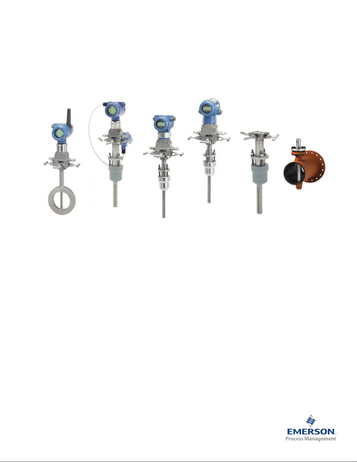
Rosemount 3051SFC_A
Compact Annubar
Flowmeter
Rosemount 3051SFA
Annubar Flowmeter
Rosemount 3051CFA
Annubar Flowmeter
Rosemount 2051CFA
Annubar Flowmeter
Rosemount 485
Annubar Primary
Element
Rosemount 585 Severe
Service Annubar Primary
Element
00809-0100-4809, Rev DA
September 2015
The Rosemount® Annubar® Flowmeter Series
Page 2

Page 3

Reference Manual
00809-0100-4809, Rev DA
Contents
1Section 1: Introduction
2Section 2: Installation
Contents
September 2015
1.1 Using this manual. . . . . . . . . . . . . . . . . . . . . . . . . . . . . . . . . . . . . . . . . . . . . . . . . . . . . . . 1
1.2 Product recycling/disposal . . . . . . . . . . . . . . . . . . . . . . . . . . . . . . . . . . . . . . . . . . . . . . .2
2.1 Safety messages. . . . . . . . . . . . . . . . . . . . . . . . . . . . . . . . . . . . . . . . . . . . . . . . . . . . . . . .3
2.2 Receiving and inspection . . . . . . . . . . . . . . . . . . . . . . . . . . . . . . . . . . . . . . . . . . . . . . . .3
2.3 Considerations . . . . . . . . . . . . . . . . . . . . . . . . . . . . . . . . . . . . . . . . . . . . . . . . . . . . . . . . .4
2.3.1 Limitations . . . . . . . . . . . . . . . . . . . . . . . . . . . . . . . . . . . . . . . . . . . . . . . . . . . . . . . 4
2.3.2 Environmental . . . . . . . . . . . . . . . . . . . . . . . . . . . . . . . . . . . . . . . . . . . . . . . . . . . .4
2.4 Installation flowchart and checklist . . . . . . . . . . . . . . . . . . . . . . . . . . . . . . . . . . . . . . .6
2.5 Mounting . . . . . . . . . . . . . . . . . . . . . . . . . . . . . . . . . . . . . . . . . . . . . . . . . . . . . . . . . . . . . .8
2.5.1 Tools and supplies . . . . . . . . . . . . . . . . . . . . . . . . . . . . . . . . . . . . . . . . . . . . . . . .8
2.5.2 Mounting brackets . . . . . . . . . . . . . . . . . . . . . . . . . . . . . . . . . . . . . . . . . . . . . . . .8
2.5.3 Bolt installation guidelines . . . . . . . . . . . . . . . . . . . . . . . . . . . . . . . . . . . . . . . . .8
2.5.4 Instrument manifolds . . . . . . . . . . . . . . . . . . . . . . . . . . . . . . . . . . . . . . . . . . . . .9
2.5.5 Straight run requirements. . . . . . . . . . . . . . . . . . . . . . . . . . . . . . . . . . . . . . . . .11
2.5.6 Flowmeter orientation . . . . . . . . . . . . . . . . . . . . . . . . . . . . . . . . . . . . . . . . . . . .14
2.5.7 Remote mounted transmitter . . . . . . . . . . . . . . . . . . . . . . . . . . . . . . . . . . . . .17
2.5.8 Flo-Tap models . . . . . . . . . . . . . . . . . . . . . . . . . . . . . . . . . . . . . . . . . . . . . . . . . .19
2.6 Installation. . . . . . . . . . . . . . . . . . . . . . . . . . . . . . . . . . . . . . . . . . . . . . . . . . . . . . . . . . . .22
2.6.1 Pak-Lok Annubar sensor type (for 485 Annubar Flowmeters) . . . . . . . . . .22
2.6.2 Flanged with opposite side support Annubar sensor type
(for 485 and 585 Annubar Flowmeters) . . . . . . . . . . . . . . . . . . . . . . . . . . . . .28
2.6.3 Flange-Lok model (for 485 Annubar Flowmeters) . . . . . . . . . . . . . . . . . . . .34
2.6.4 Threaded Flo-tap (for 485 Annubar Flowmeter) . . . . . . . . . . . . . . . . . . . . . .41
2.6.5 Flanged Flo-tap (for 485 and 585 Annubar Flowmeters). . . . . . . . . . . . . . .47
2.6.6 Main steam line (for 585 Annubar Flowmeters) . . . . . . . . . . . . . . . . . . . . . .55
2.7 Wire the transmitter . . . . . . . . . . . . . . . . . . . . . . . . . . . . . . . . . . . . . . . . . . . . . . . . . . .59
2.7.1 Wiring diagrams . . . . . . . . . . . . . . . . . . . . . . . . . . . . . . . . . . . . . . . . . . . . . . . . .59
Content s
iii
Page 4

Contents
September 2015
Reference Manual
00809-0100-4809, Rev DA
3Section 3: Commissioning
3.1 Safety messages. . . . . . . . . . . . . . . . . . . . . . . . . . . . . . . . . . . . . . . . . . . . . . . . . . . . . . .61
3.2 Transmitter commissioning. . . . . . . . . . . . . . . . . . . . . . . . . . . . . . . . . . . . . . . . . . . . .62
3.3 Commissioning the Annubar sensor. . . . . . . . . . . . . . . . . . . . . . . . . . . . . . . . . . . . . .62
3.3.1 Direct mount transmitter . . . . . . . . . . . . . . . . . . . . . . . . . . . . . . . . . . . . . . . . .62
3.3.2 Remote mount transmitter. . . . . . . . . . . . . . . . . . . . . . . . . . . . . . . . . . . . . . . .68
4Section 4: Operation and Maintenance
4.1 Safety messages. . . . . . . . . . . . . . . . . . . . . . . . . . . . . . . . . . . . . . . . . . . . . . . . . . . . . . .75
4.2 RTD maintenance. . . . . . . . . . . . . . . . . . . . . . . . . . . . . . . . . . . . . . . . . . . . . . . . . . . . . .75
4.2.1 Replacing an RTD . . . . . . . . . . . . . . . . . . . . . . . . . . . . . . . . . . . . . . . . . . . . . . . .75
4.2.2 Electrical RTD check procedure . . . . . . . . . . . . . . . . . . . . . . . . . . . . . . . . . . . .78
4.3 Pak-Lok, Flange-Lok, and Flo-Tap maintenance . . . . . . . . . . . . . . . . . . . . . . . . . . . .79
4.4 Gas entrapment . . . . . . . . . . . . . . . . . . . . . . . . . . . . . . . . . . . . . . . . . . . . . . . . . . . . . . .80
4.5 Dirt accumulation . . . . . . . . . . . . . . . . . . . . . . . . . . . . . . . . . . . . . . . . . . . . . . . . . . . . .80
4.6 Main steam line Annubar sensor maintenance. . . . . . . . . . . . . . . . . . . . . . . . . . . . .81
5Section 5: Troubleshooting
5.1 Basic troubleshooting . . . . . . . . . . . . . . . . . . . . . . . . . . . . . . . . . . . . . . . . . . . . . . . . . .83
5.2 Return of materials . . . . . . . . . . . . . . . . . . . . . . . . . . . . . . . . . . . . . . . . . . . . . . . . . . . .85
AAppendix A: Specifications and Reference Data
A.1 3051SFA ordering information . . . . . . . . . . . . . . . . . . . . . . . . . . . . . . . . . . . . . . . . . .87
A.1.1 Rosemount® 3051SFA Annubar® Flowmeter . . . . . . . . . . . . . . . . . . . . . . .87
A.2 3051SFC ordering information . . . . . . . . . . . . . . . . . . . . . . . . . . . . . . . . . . . . . . . . 100
A.3 3051SF specifications . . . . . . . . . . . . . . . . . . . . . . . . . . . . . . . . . . . . . . . . . . . . . . . . 109
A.3.1 Performance specifications. . . . . . . . . . . . . . . . . . . . . . . . . . . . . . . . . . . . . . 109
A.3.2 Functional specifications. . . . . . . . . . . . . . . . . . . . . . . . . . . . . . . . . . . . . . . . 111
A.3.3 Physical specifications . . . . . . . . . . . . . . . . . . . . . . . . . . . . . . . . . . . . . . . . . . 116
A.4 3051CFA ordering information . . . . . . . . . . . . . . . . . . . . . . . . . . . . . . . . . . . . . . . . 117
A.4.1 Rosemount 3051CFA Annubar Flowmeter . . . . . . . . . . . . . . . . . . . . . . . . 117
A.5 3051CFC ordering information . . . . . . . . . . . . . . . . . . . . . . . . . . . . . . . . . . . . . . . . 126
A.5.1 Rosemount 3051CFC Compact Flowmeter . . . . . . . . . . . . . . . . . . . . . . . . 126
A.6 3051CF specifications . . . . . . . . . . . . . . . . . . . . . . . . . . . . . . . . . . . . . . . . . . . . . . . . 132
A.6.1 Performance specifications. . . . . . . . . . . . . . . . . . . . . . . . . . . . . . . . . . . . . . 132
A.6.2 Functional specifications. . . . . . . . . . . . . . . . . . . . . . . . . . . . . . . . . . . . . . . . 132
A.6.3 Physical specifications . . . . . . . . . . . . . . . . . . . . . . . . . . . . . . . . . . . . . . . . . . 135
A.7 2051CFA ordering information . . . . . . . . . . . . . . . . . . . . . . . . . . . . . . . . . . . . . . . . 136
iv
Content s
Page 5

Reference Manual
00809-0100-4809, Rev DA
Contents
September 2015
A.8 2051CFC ordering information . . . . . . . . . . . . . . . . . . . . . . . . . . . . . . . . . . . . . . . . 143
A.8.1 Rosemount 2051CFC Compact Flowmeter . . . . . . . . . . . . . . . . . . . . . . . . 143
A.9 2051CF specifications . . . . . . . . . . . . . . . . . . . . . . . . . . . . . . . . . . . . . . . . . . . . . . . . 149
A.9.1 Performance specifications. . . . . . . . . . . . . . . . . . . . . . . . . . . . . . . . . . . . . . 149
A.9.2 Functional specifications. . . . . . . . . . . . . . . . . . . . . . . . . . . . . . . . . . . . . . . . 149
A.9.3 Physical specifications . . . . . . . . . . . . . . . . . . . . . . . . . . . . . . . . . . . . . . . . . . 154
A.10 485 Annubar primary element ordering information . . . . . . . . . . . . . . . . . . . . 155
A.11 485 specifications. . . . . . . . . . . . . . . . . . . . . . . . . . . . . . . . . . . . . . . . . . . . . . . . . . . 161
A.11.1 Performance specifications . . . . . . . . . . . . . . . . . . . . . . . . . . . . . . . . . . . . . 161
A.11.2 Functional specifications . . . . . . . . . . . . . . . . . . . . . . . . . . . . . . . . . . . . . . . 161
A.11.3 Physical specifications . . . . . . . . . . . . . . . . . . . . . . . . . . . . . . . . . . . . . . . . . 162
A.12 585 Annubar primary element ordering information . . . . . . . . . . . . . . . . . . . . 165
A.13 585 specifications. . . . . . . . . . . . . . . . . . . . . . . . . . . . . . . . . . . . . . . . . . . . . . . . . . . 170
A.13.1 Performance specifications . . . . . . . . . . . . . . . . . . . . . . . . . . . . . . . . . . . . . 170
A.13.2 Functional specifications . . . . . . . . . . . . . . . . . . . . . . . . . . . . . . . . . . . . . . . 170
A.13.3 Physical specifications . . . . . . . . . . . . . . . . . . . . . . . . . . . . . . . . . . . . . . . . . 171
A.14 405 Compact primary element ordering information. . . . . . . . . . . . . . . . . . . . 173
A.15 405 Specifications . . . . . . . . . . . . . . . . . . . . . . . . . . . . . . . . . . . . . . . . . . . . . . . . . . 176
A.15.1 Performance specifications . . . . . . . . . . . . . . . . . . . . . . . . . . . . . . . . . . . . . 176
A.15.2 Functional specifications . . . . . . . . . . . . . . . . . . . . . . . . . . . . . . . . . . . . . . . 176
A.15.3 Physical specifications . . . . . . . . . . . . . . . . . . . . . . . . . . . . . . . . . . . . . . . . . 177
A.16 Dimensional drawings. . . . . . . . . . . . . . . . . . . . . . . . . . . . . . . . . . . . . . . . . . . . . . . 178
A.16.1 3051SF dimensional drawings . . . . . . . . . . . . . . . . . . . . . . . . . . . . . . . . . . 178
A.16.2 3051CF dimensional drawings . . . . . . . . . . . . . . . . . . . . . . . . . . . . . . . . . . 187
A.16.3 2051CF dimensional drawings . . . . . . . . . . . . . . . . . . . . . . . . . . . . . . . . . . 196
A.16.4 485 dimensional drawings. . . . . . . . . . . . . . . . . . . . . . . . . . . . . . . . . . . . . . 200
A.16.5 585 dimensional drawings. . . . . . . . . . . . . . . . . . . . . . . . . . . . . . . . . . . . . . 208
A.16.6 405 Dimensional drawings . . . . . . . . . . . . . . . . . . . . . . . . . . . . . . . . . . . . . 212
BAppendix B: Product Certifications
B.1 Hazardous Locations Installations. . . . . . . . . . . . . . . . . . . . . . . . . . . . . . . . . . . . . . 213
B.2 Rosemount® 3051SFA and 3051SFC_A . . . . . . . . . . . . . . . . . . . . . . . . . . . . . . . . 213
B.2.1 European Directive Information. . . . . . . . . . . . . . . . . . . . . . . . . . . . . . . . . . 213
B.2.2 Ordinary Location Certification . . . . . . . . . . . . . . . . . . . . . . . . . . . . . . . . . . 213
Content s
B.2.3 Installing Equipment in North America. . . . . . . . . . . . . . . . . . . . . . . . . . . . 213
B.3 Rosemount 3051CFA and 3051CFC_A. . . . . . . . . . . . . . . . . . . . . . . . . . . . . . . . . . 218
B.3.1 European Directive Information. . . . . . . . . . . . . . . . . . . . . . . . . . . . . . . . . . 218
B.3.2 Ordinary Location Certification . . . . . . . . . . . . . . . . . . . . . . . . . . . . . . . . . . 218
v
Page 6

Contents
September 2015
Reference Manual
00809-0100-4809, Rev DA
B.4 Rosemount 2051CFA and 2051CFC_A. . . . . . . . . . . . . . . . . . . . . . . . . . . . . . . . . . 224
B.4.1 European Directive Information. . . . . . . . . . . . . . . . . . . . . . . . . . . . . . . . . . 224
B.4.2 Ordinary Location Certification . . . . . . . . . . . . . . . . . . . . . . . . . . . . . . . . . . 224
B.5 Installation Drawings. . . . . . . . . . . . . . . . . . . . . . . . . . . . . . . . . . . . . . . . . . . . . . . . . 229
B.5.1 Rosemount 3051SFA ProBar Flowmeter . . . . . . . . . . . . . . . . . . . . . . . . . . 229
B.5.2 Rosemount 3051SFC_A Flowmeter . . . . . . . . . . . . . . . . . . . . . . . . . . . . . . 229
vi
Content s
Page 7

Title Page
NOTICE
September 2015
Reference Manual
00809-0100-4809, Rev DA
The Rosemount® Annubar®
Flowmeter Series
Read this manual before working with the product. For personal and system safety, and for
optimum product performance, make sure you thoroughly understand the contents before
installing, using, or maintaining this product.
The United States has two toll-free assistance numbers and one International number.
Customer Central
1-800-999-9307 (7:00 A.M. to 7:00 P.M. CST)
International
1-(952) 906-8888
National Response Center
1-800-654-7768 (24 hours a day)
Equipment service needs
Explosions could result in death or serious injury.
Do not remove the transmitter cover in explosive atmospheres when the circuit is live.
Before connecting a Field Communicator in an explosive atmosphere, make sure the
instruments in the loop are installed in accordance with intrinsically safe or
non-incendive field wiring practices.
Verify the operating atmosphere of the transmitter is consistent with the appropriate
hazardous locations certifications.
Both transmitter covers must be fully engaged to meet explosion-proof requirements.
Failure to follow these installation guidelines could result in death or serious injury.
Make sure only qualified personnel perform the installation.
If the line is pressurized, serious injury or death could occur by opening valves.
Electrical shock can result in death or serious injury.
Avoid contact with the leads and the terminals.
vii
Page 8

Title Page
September 2015
Reference Manual
00809-0100-4809, Rev DA
The products described in this document are NOT designed for nuclear-qualified
applications. Using non-nuclear qualified products in applications that require
nuclear-qualified hardware or products may cause inaccurate readings.
For information on Rosemount nuclear-qualified products, contact your local Emerson
™
Process Management Sales Representative.
This device is intended for use in temperature monitoring applications and should not be
used in control and safety applications.
If pipe/duct wall is less than 0.125-in. (3.2mm) use extreme caution when installing sensor.
Thin walls can deform during welding, installation, or from the weight of a cantilevered
flowmeter. These installations may require a fabricated outlet, saddle, or external
flowmeter support. Consult factory for assistance.
viii
Page 9

Reference Manual
00809-0100-4809, Rev DA
Section 1 Introduction
1.1 Using this manual
This product manual provides installation, configuration, calibration, troubleshooting, and
maintenance instructions for the Rosemount
®
Annubar® Flowmeter Series.
Section 1: Introduction
September 2015
Section 2: Installation
Installation flowchart and checklist
Orienting, mounting, and installing the flowmeter
Connecting the Wiring
Section 3: Commissioning
Calibrating the flowmeter
Section 4: Operation and Maintenance
Troubleshooting information
Disassembly
RTD maintenance
Appendix A: Specifications and Reference Data
Specifications
Dimensional drawings
Appendix B: Product Certifications
Approvals certifications
Installation drawings
Introduction
Information in this manual applies to circular pipes only. Consult Rosemount Customer Central
for instructions regarding use in square or rectangular ducts.
1
Page 10

Section 1: Introduction
September 2015
1.2 Product recycling/disposal
Recycling of equipment and packaging should be taken into consideration and disposed of in
accordance with local and national legislation/regulations.
Reference Manual
00809-0100-4809, Rev DA
2
Introduction
Page 11
Reference Manual
00809-0100-4809, Rev DA
Section 2 Installation
Safety messages . . . . . . . . . . . . . . . . . . . . . . . . . . . . . . . . . . . . . . . . . . . . . . . . . . . . . . . . . . . . page 3
Receiving and inspection . . . . . . . . . . . . . . . . . . . . . . . . . . . . . . . . . . . . . . . . . . . . . . . . . . . . page 3
Considerations . . . . . . . . . . . . . . . . . . . . . . . . . . . . . . . . . . . . . . . . . . . . . . . . . . . . . . . . . . . . . page 4
Installation flowchart and checklist . . . . . . . . . . . . . . . . . . . . . . . . . . . . . . . . . . . . . . . . . . . . page 6
Mounting . . . . . . . . . . . . . . . . . . . . . . . . . . . . . . . . . . . . . . . . . . . . . . . . . . . . . . . . . . . . . . . . . . page 8
Installation . . . . . . . . . . . . . . . . . . . . . . . . . . . . . . . . . . . . . . . . . . . . . . . . . . . . . . . . . . . . . . . . . page 22
Wire the transmitter . . . . . . . . . . . . . . . . . . . . . . . . . . . . . . . . . . . . . . . . . . . . . . . . . . . . . . . . page 59
2.1 Safety messages
Instructions and procedures in this section may require special precautions to ensure the safety
of the personnel performing the operations. Refer to the following safety messages before
performing any operation in this section.
Section 2: Installation
September 2015
If pipe/duct wall is less than 0.125-in. (3.2mm) use extreme caution when installing sensor.
Thin walls can deform during welding, installation, or from the weight of a cantilevered
flowmeter. These installations may require a fabricated outlet, saddle, or external
flowmeter support. Consult factory for assistance.
Explosions could result in death or serious injury.
Do not remove the transmitter cover in explosive atmospheres when the circuit is live.
Before connecting a Field Communicator in an explosive atmosphere, make sure the
instruments in the loop are installed in accordance with intrinsically safe or
non-incendive field wiring practices.
Verify the operating atmosphere of the transmitter is consistent with the appropriate
hazardous locations certifications.
Both transmitter covers must be fully engaged to meet explosion-proof requirements.
Failure to follow these installation guidelines could result in death or serious injury.
Make sure only qualified personnel perform the installation.
2.2 Receiving and inspection
Flowmeters are available in different models and with different options, so it is important to
inspect and verify that the appropriate model was delivered before installation.
Upon receipt of the shipment, check the packing list against the material received and the
purchase order. All items are tagged with a sales order number, serial number, and customer tag
number. Report any damage to the carrier.
3Installation
Page 12
Section 2: Installation
September 2015
2.3 Considerations
2.3.1 Limitations
Structural
Structural limitations are printed on the sensor tag. Exceeding structural limitations may cause
sensor failure.
Functional
The most accurate and repeatable flow measurement occurs in the following conditions:
The structural limit differential pressure, as printed on the sensor tag, is not exceeded.
The instrument is not used for two-phase flow or for steam service below saturation
temperature.
Install the flowmeter in the correct location within the piping branch to prevent
measurement inaccuracies caused by flow disturbances.
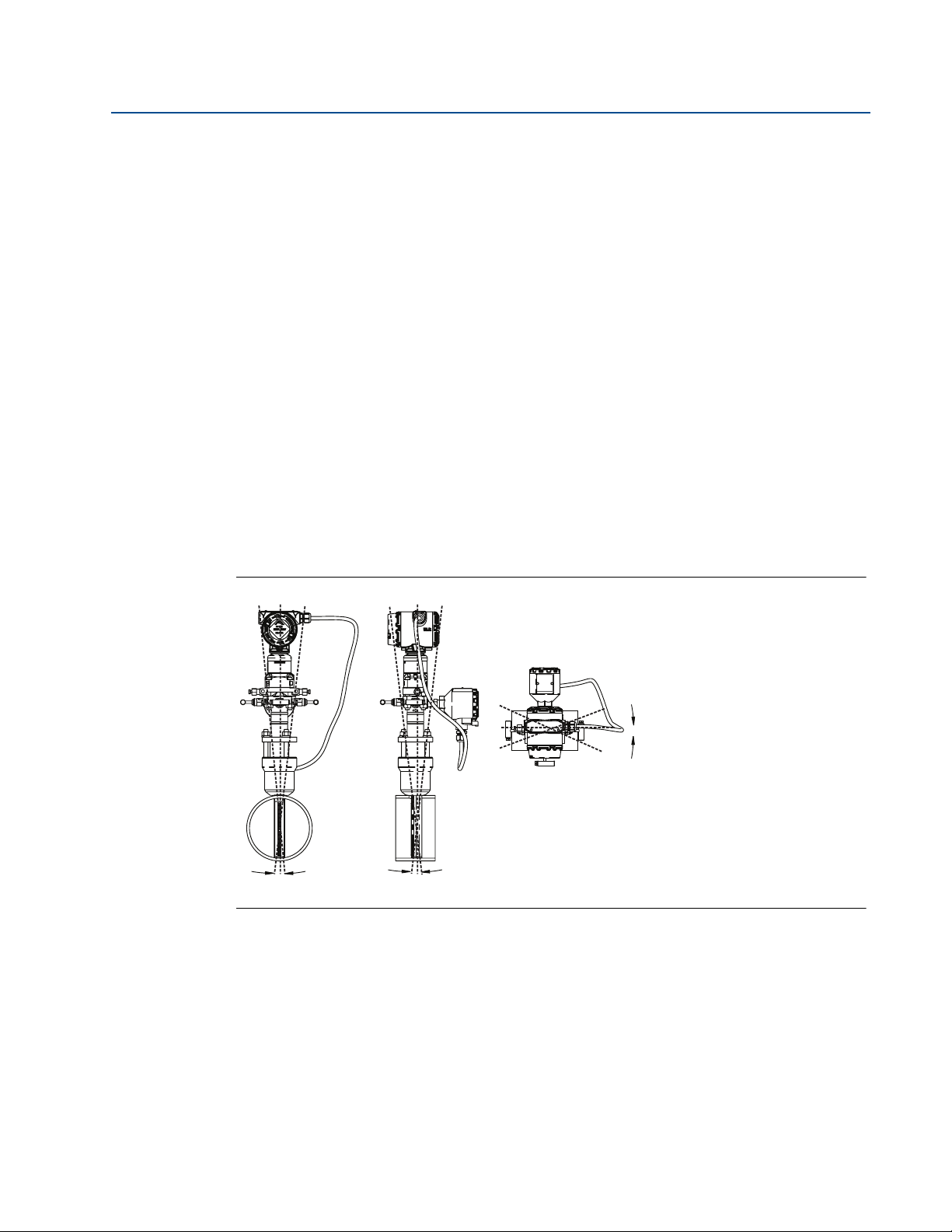
The flowmeter can be installed with a maximum misalignment of 3 degrees (see Figure
2-1). Misalignment beyond 3 degrees will cause flow measurement errors.
Reference Manual
00809-0100-4809, Rev DA
Figure 2-1. Permissible Misalignment
3° max. 3° max.
2.3.2 Environmental
Mount the flowmeter in a location with minimal ambient temperature changes. Appendix A:
Specifications and Reference Data lists the temperature operating limits. Mount to avoid
vibration, mechanical shock, and external contact with corrosive materials.
3° max.
Access requirements
Consider the need to access the flowmeter when choosing an installation location and
orientation.
4
Installation
Page 13
Reference Manual
00809-0100-4809, Rev DA
Process flange orientation
Orient the process flanges on a remote mounted flowmeter so that process connections can be
made. For safety reasons, orient the drain/vent valves so that process fluid is directed away from
technicians when the valves are used. In addition, consider the possible need for a testing or
calibration input.
Housing rotation
The electronics housing may be rotated up to 180 degrees (left or right) to improve field access
to the two compartments or to better view the optional LCD meter. To rotate the housing,
release the housing rotation set screw and turn the housing up to 180 degrees.
Electronics housing
Terminal side
The circuit compartment should not routinely need to be opened when the unit is in service.
Wiring connections are made through the conduit openings on the top or side of the housing.
The field terminal side is marked on the electronics housing. Mount the flowmeter so that the
terminal side is accessible. A 0.75-in. (19 mm) clearance is required for cover removal. Use a
conduit plug on the unused side of the conduit opening. A 3-in. (76 mm) clearance is required
for cover removal if a meter is installed.
Section 2: Installation
September 2015
Cover installations
Always install the electronics housing covers metal-to-metal to ensure a proper seal.
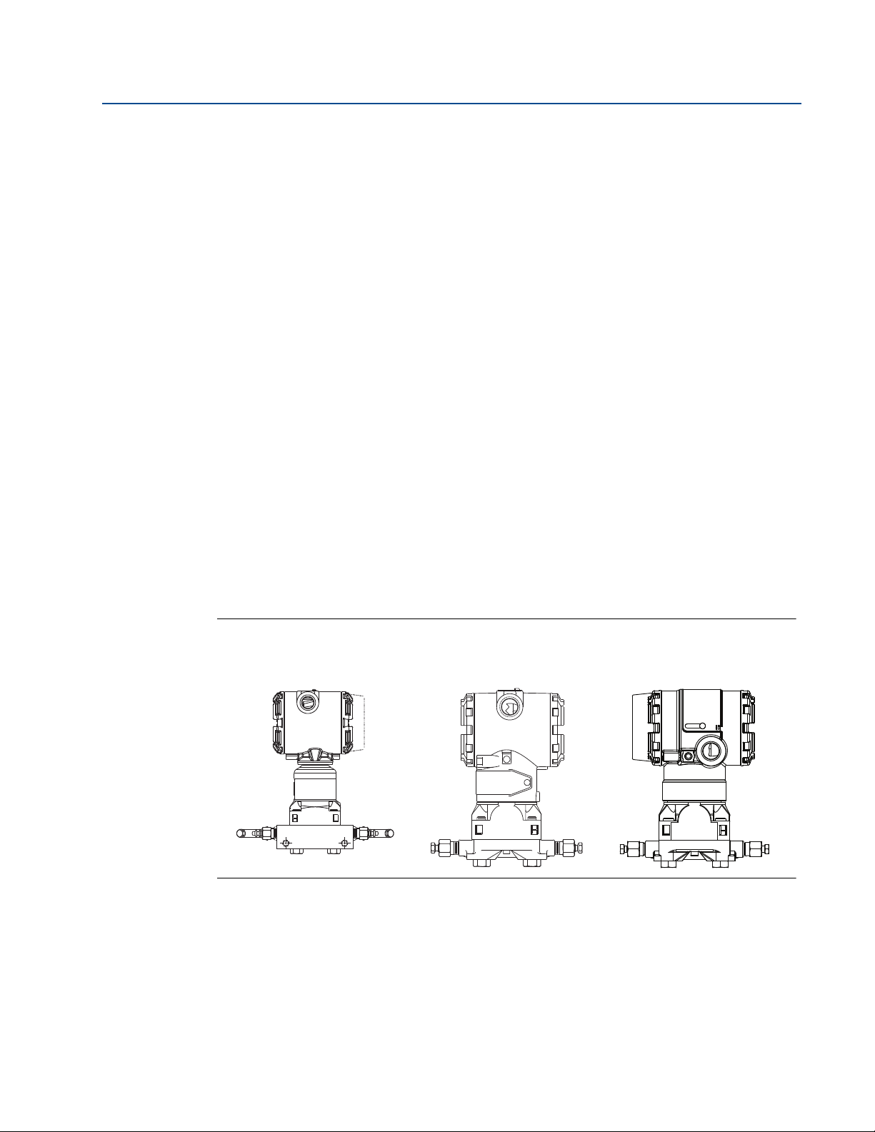
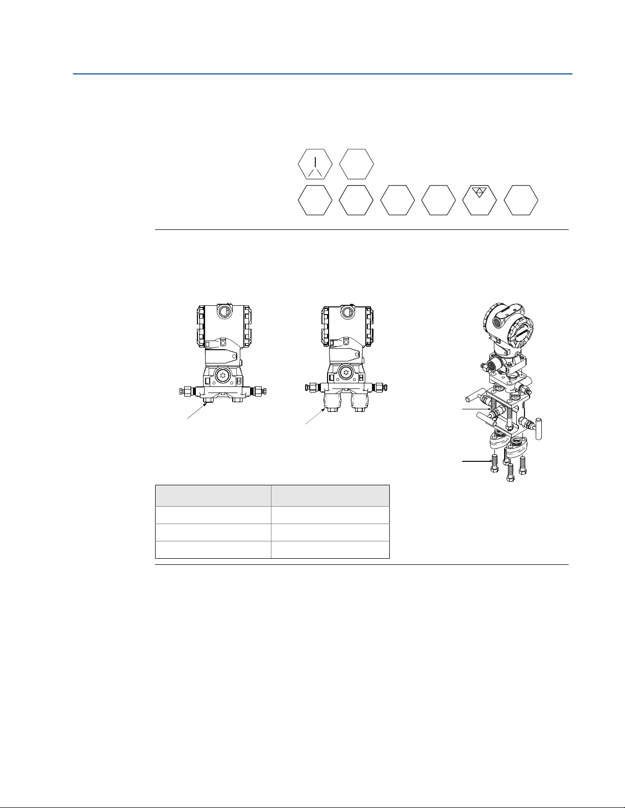
Figure 2-2. Transmitter Housing
Rosemount® 3051S
MultiVariable
™
Transmitter
Rosemount 3051C
Tra ns mitt er
Rosemount 2051C
Tra ns mitt er
Installation
5
Page 14
Section 2: Installation
September 2015
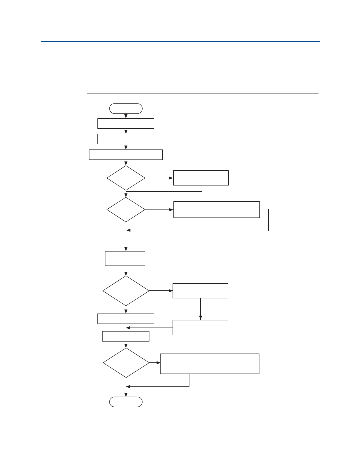
2.4 Installation flowchart and checklist
Figure 2-3 is an installation flowchart that provides guidance through the installation process.
Following the figure, an installation checklist has been provided to verify that all critical steps
have been taken in the installation process. The checklist numbers are indicated in the
flowchart.
Figure 2-3. Installation Chart
Start
Unpack instrument
Review product manual
Verify proper installation location Steps 1, 2
Reference Manual
00809-0100-4809, Rev DA
Step 4
Step 5-9
Hazardous
location?
No
Bench
configure?
No
Verify model
indicated on tag
Remote
mounted
transmitter
No
Install flowmeter
Wire
Yes
Yes
Yes
Review Appendix B
See appropriate transmitter manual
for bench configuration information
Install hardware
Install transmitter
Step 3
Remote
mounted
electronics?
No
Finish
6
Step 11-14
Commission the transmitter. See appropriate
transmitter manual for bench configuration
information.
Installation
Page 15

Reference Manual
00809-0100-4809, Rev DA
The following is a summary of the steps required to complete a flowmeter installation. If this is a
new installation, begin with Step 1. If the mounting is already in place, verify the hole size and
fittings match the recommended specifications (see Table 2-3 on page 23) and begin with Step
5.
1. Determine where the flowmeter is to be placed within the piping system.
2. Establish the proper orientation as determined by the intended application.
3. Review Appendix B: Product Certifications and determine if the flowmeter is located in
4. Confirm the configuration.
5. Drill the correct sized hole into the pipe and deburr. Do not torch-cut holes. If installing
6. For instruments equipped with opposite-side support, drill a second hole 180° from the
Section 2: Installation
September 2015
a hazardous location.
a wafer-style Annubar flowmeter, place the flowmeter between raised-face flanges,
utilizing the centering ring to install the flowmeter, and skip to Step 11.
first hole.
7. Weld the mounting per plant welding procedures.
8. Measure the pipe’s internal diameter (ID), preferably at 1 ⫻ ID from the hole (upstream
or downstream).
Note
To maintain published flowmeter accuracy, provide the pipe ID when purchasing the flowmeter.
9. Check the set-up of the instrument assembly to the pipe.
10. Install the flowmeter.
11. Wire the instrument.
12. Supply power to the flowmeter.
13. Perform a trim for mounting effects.
14. Check for leaks.
15. Commission the instrument.
Installation
7
Page 16

Section 2: Installation
September 2015
2.5 Mounting
2.5.1 Tools and supplies
Tools required include the following:
Open end or combination wrenches (spanners) to fit the pipe fittings and bolts:
Adjustable wrench: 15-in. (1
Nut driver:
#1 Phillip’s screwdriver
Standard screwdrivers:
14-in. Pipe wrench
Wire cutters/strippers
Supplies required include the following:
Fittings including (but not limited to)
5
/8-in., and 7/8-in
3
/8-in. for vent/drain valves (or 3/8-in. wrench)
7
/16-in. box wrench (required for the ferry head bolt design)
1
/2-in. tubing or 1/2-in. pipe (recommended) to hook up the electronics to the sensor
probe. The length required depends upon the distance between the electronics and the
sensor
1
/2-in. jaw)
1
/4-in. and 1/8-in. wide
Reference Manual
00809-0100-4809, Rev DA
9
/16-in.,
– Two tube or pipe tees (for steam or high temperature liquid) and
– Six tube/pipe fittings (for tube)
Pipe compound or PTFE tape (where local piping codes allow)
2.5.2 Mounting brackets
Mounting brackets are provided with any flowmeter order with a remote mounted transmitter to
facilitate mounting to a panel, wall, or 2-in. (50.8 mm) pipe. The bracket option for use with the
Coplanar flange is 316 SST with 316 SST bolts.
When installing the transmitter to one of the mounting brackets, torque the bolts to 125 in-lb.
(169 N-m).
2.5.3 Bolt installation guidelines
The following guidelines have been established to ensure a tight flange, adapter, or manifold
seal. Only use bolts supplied with the instrument or sold by the factory.
The instrument is shipped with the coplanar flange installed with four 1.75-in. (44.5 mm) flange
bolts. The following bolts also are supplied to facilitate other mounting configurations:
Four 2.25-in. (57.2 mm) manifold/flange bolts for mounting the coplanar flange on a
three-valve manifold. In this configuration, the 1.75-in. (44.5 mm) bolts may be used to
mount the flange adapters to the process connection side of the manifold.
(Optional) If flange adapters are ordered, four 2.88-in. (73.2 mm) flange/adapter bolts
for mounting the flange adapters to the coplanar flange.
8
Installation
Page 17
Reference Manual
B7M
316
316
®
B8M
STM
316
316
SW
316
2.25 (57) × 4
1.75 (44) × 4
00809-0100-4809, Rev DA
Stainless steel bolts supplied by Rosemount Inc. are coated with a lubricant to ease installation.
Carbon steel bolts do not require lubrication. Do not apply additional lubricant when installing
either type of bolt. Bolts supplied by Rosemount Inc. are identified by the following head
markings:
Figure 2-4. Coplanar Mounting Bolts and Bolting Configurations for Coplanar Flange
Carbon Steel Head Markings
(CS)
Stainless Steel Head Markings
(SST)
Transmitter with
flange bolts
Transmitter with
optional flange adapters
and flange/adapter bolts
Section 2: Installation
September 2015
Transmitter with 3-valve manifold,
manifold/flange bolts,
flange adapters, and
flange/adapter bolts
1.75 (44) × 4
2.88 (73) × 4
Description Size in. (mm)
Flange bolts (4) 1.75-in. (44 mm)
Flange/adapter bolts (4) 2.88-in. (73 mm)
Manifold/flange bolts (4) 2.25-in. (57 mm)
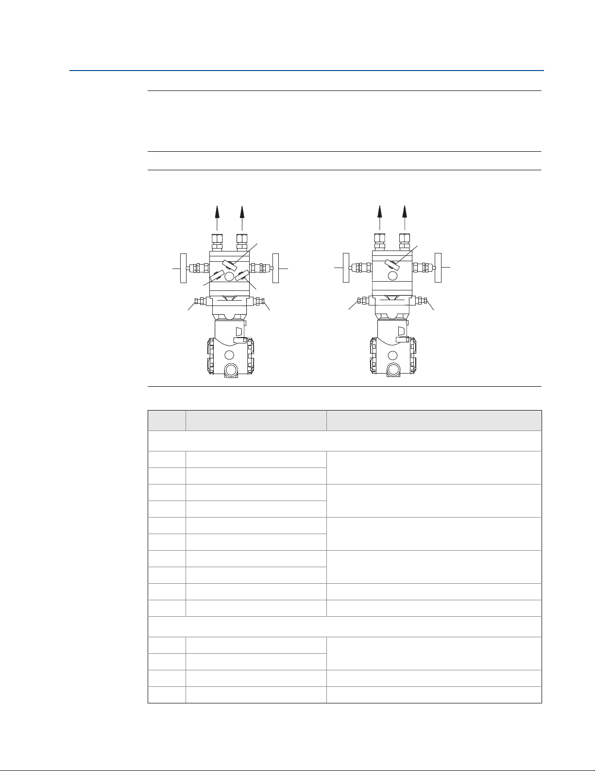
2.5.4 Instrument manifolds
Figure 2-5 on page 10 identifies the valves on a 5-valve and a 3-valve manifold. Table 2-1 on
page 10 explains the purpose of these valves.
An instrument manifold is recommended for all installations. A manifold allows an operator to
equalize the pressures prior to the zero calibration of the transmitter as well as to isolate the
electronics from the rest of the system without disconnecting the impulse piping. Although a
3-valve manifold can be used, a 5-valve manifold is recommended.
5-valve manifolds provide a positive method of indicating a partially closed or faulty equalizer
valve. A closed faulty equalizer valve will block the DP signal and create errors that may not be
detectable otherwise. The labels for each valve will be used to identify the proper valve in the
procedures to follow.
Installation
9
Page 18
Section 2: Installation
To PH To PL
MV
ML
MEL
DVL
MH
MEH
DVH
2
1
To PL
ME
To PH
MH
DVH
ML
DVL
2
1
September 2015
Note
Some recently-designed instrument manifolds have a single valve actuator, but cannot perform
all of the functions available on standard 5-valve units. Check with the manufacturer to verify
the functions that a particular manifold can perform. In place of a manifold, individual valves
may be arranged to provide the necessary isolation and equalization functions.
Figure 2-5. Valve Identification for 5-Valve and 3-Valve Manifolds
Reference Manual
00809-0100-4809, Rev DA
5-valve manifold 3-valve manifold
Table 2-1. Description of Impulse Valves and Components
Name Description Purpose
Manifold and impulse pipe valves
PH Primary Sensor – High Pressure
PL Primary Sensor – Low Pressure
DVH Drain/Vent Valve – High Pressure
DVL Drain/Vent Valve – Low Pressure
MH Manifold – High Pressure
ML Manifold – Low Pressure
MEH Manifold Equalizer – High Pressure
MEL Manifold Equalizer – Low Pressure
ME Manifold Equalizer Allows high and low side pressure to equalize
MV Manifold Vent Valve Vents process fluid
Isolates the flowmeter sensor from the impulse piping
system
Drains (for gas service) or vents (for liquid or steam
service) the DP electronics chambers
Isolates high side or low side pressure from the
process.
Allows high and low pressure side access to the vent
valve, or for isolating the process fluid
Components
1 Tr an sm i tt er
2 Manifold
3 Vent Chambers Collects gases in liquid applications.
4 Condensate Chamber Collects condensate in gas applications.
Reads Differential Pressure
Isolates and equalizes transmitter
10
Installation
Page 19

Reference Manual
00809-0100-4809, Rev DA
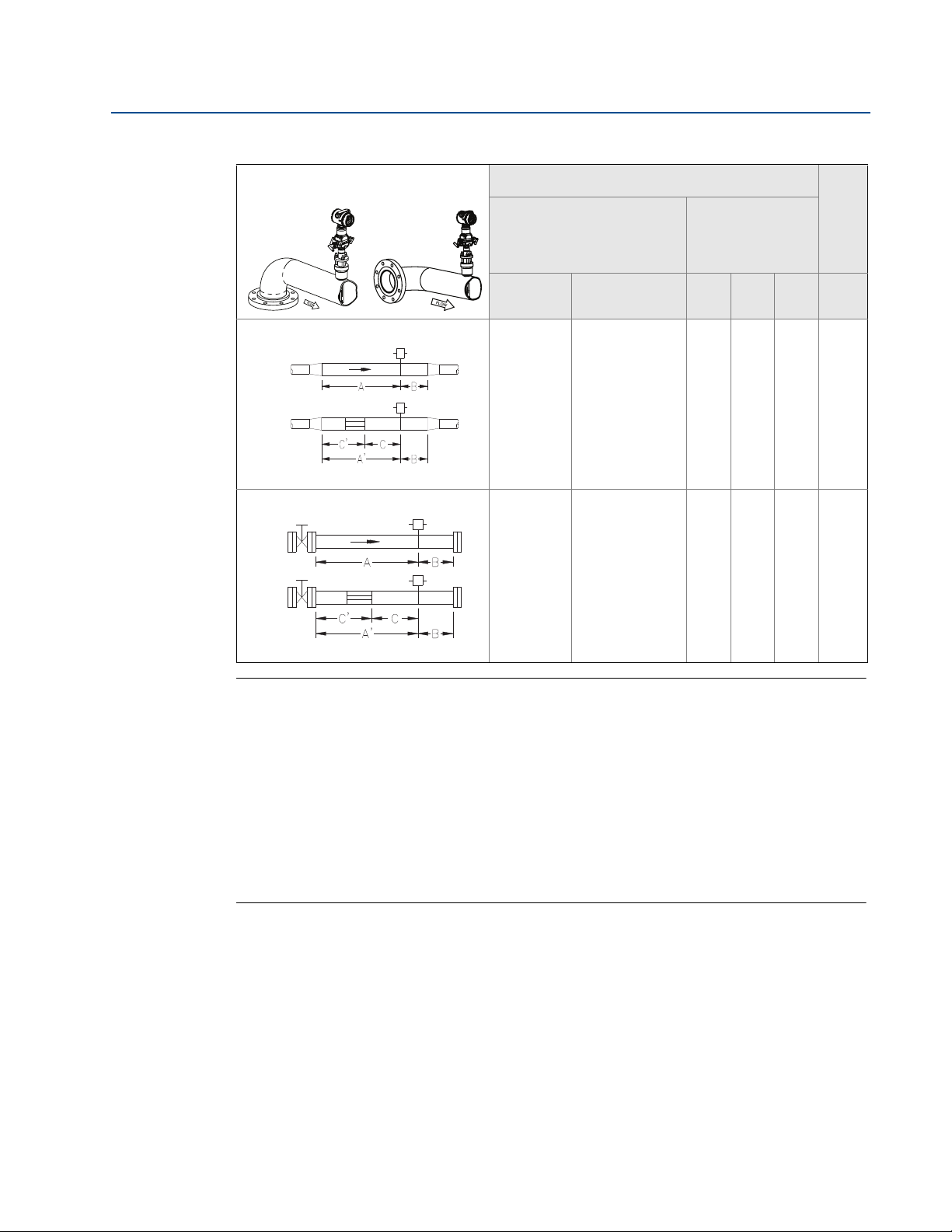
2.5.5 Straight run requirements
Use the following to aid in determining the straight run requirements.
Table 2-2. Straight Run Requirements
Section 2: Installation
September 2015
In plane Out of plane
Single elbow
1
Single elbow with straightening vanes
Double elbows in plane
2
Upstream dimensions
Without straightening
vanes
With
straightening
vanes
In plane A Out of plane A A’ C C’ B
8
N/A
11
N/A
10
N/A
16
N/A
N/A8N/A4N/A44
N/A8N/A4N/A44
dimensions
Downstream
4
4
Installation
Double elbow in plane with straightening
Double elbows out of plane
3
Double elbows out of plane with
4
Reducer with straightening vanes
vanes
straightening vanes
Reducer
23
N/A
12
N/A
28
N/A
12
N/A
N/A8N/A4N/A44
4
N/A8N/A4N/A44
4
11
Page 20
Section 2: Installation
September 2015
Table 2-2. Straight Run Requirements
Reference Manual
00809-0100-4809, Rev DA
In plane Out of plane
Expander
5
Expander with straightening Vanes
Valv e
6
Upstream dimensions
Without straightening
vanes
With
straightening
vanes
In plane A Out of plane A A’ C C’ B
18
N/A
30
N/A
18
N/A
30
N/A
N/A8N/A4N/A44
N/A8N/A4N/A44
dimensions
Downstream
4
4
Valve with straightening Vanes
Note
If proper lengths of straight run are not available, position the mounting such that 80%
of the run is upstream and 20% is downstream.
“In Plane A” means the sensor is in the same plane as the elbow. “Out of Plane A” means
the sensor is perpendicular to the plane of the elbow.
The information contained in this manual is applicable to circular pipes only. Consult
the factory for instructions regarding use in square or rectangular ducts.
Straightening vanes may be used to reduce the required straight run length.
The last row in Tab l e 2- 2 applies to gate, globe, plug, and other throttling valves that are
partially opened, as well as control valves.
12
Installation
Page 21

Reference Manual
00809-0100-4809, Rev DA
Figure 2-6. Mounting Configuration
Section 2: Installation
September 2015
Integral mount Remote mount
C
C
B
A
A. Annubar sensor
B. Mounting hardware (Annubar type)
A
C. Transmitter
B
Note
The direct-mounted flowmeter is usually shipped with the transmitter assembled to the sensor,
unless it is ordered with a Remote-mount Transmitter Connection Platform.
Installation
13
Page 22
Section 2: Installation
Flow
360°
Note: Downward flow is not recommended.
September 2015
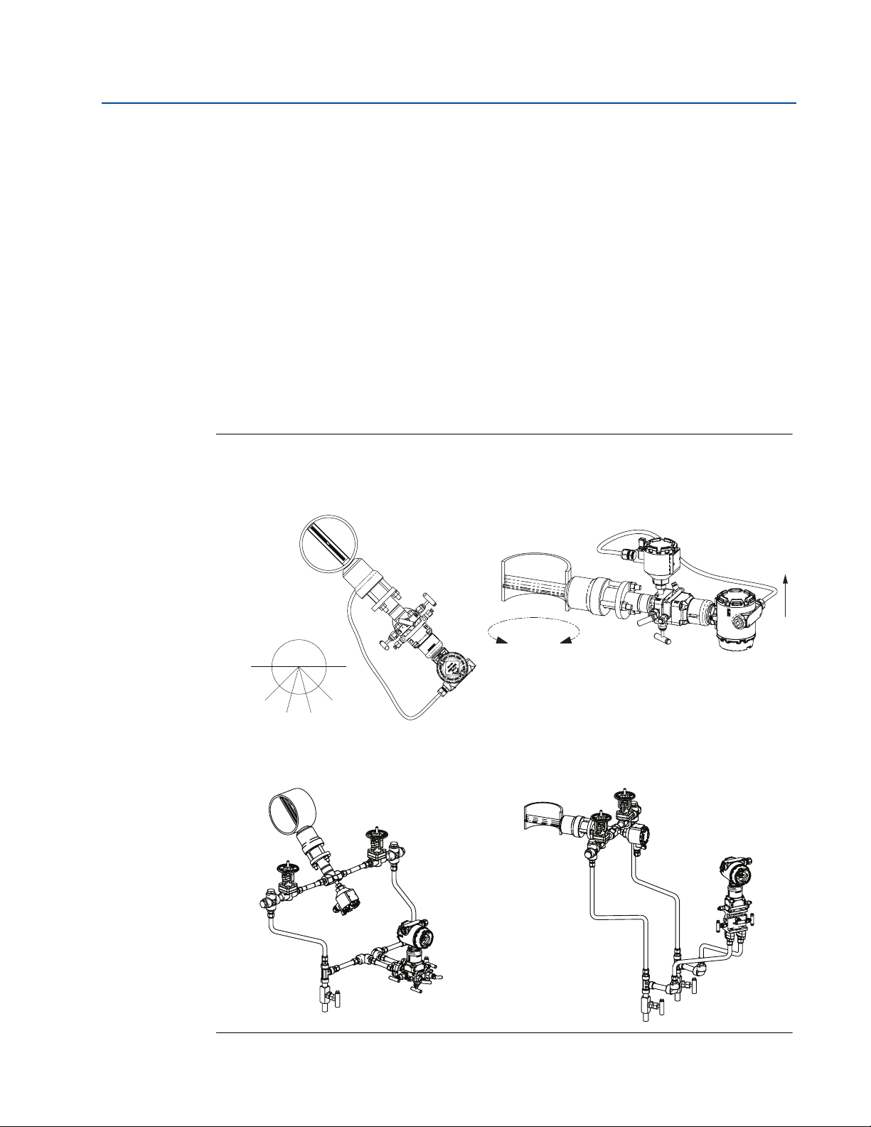
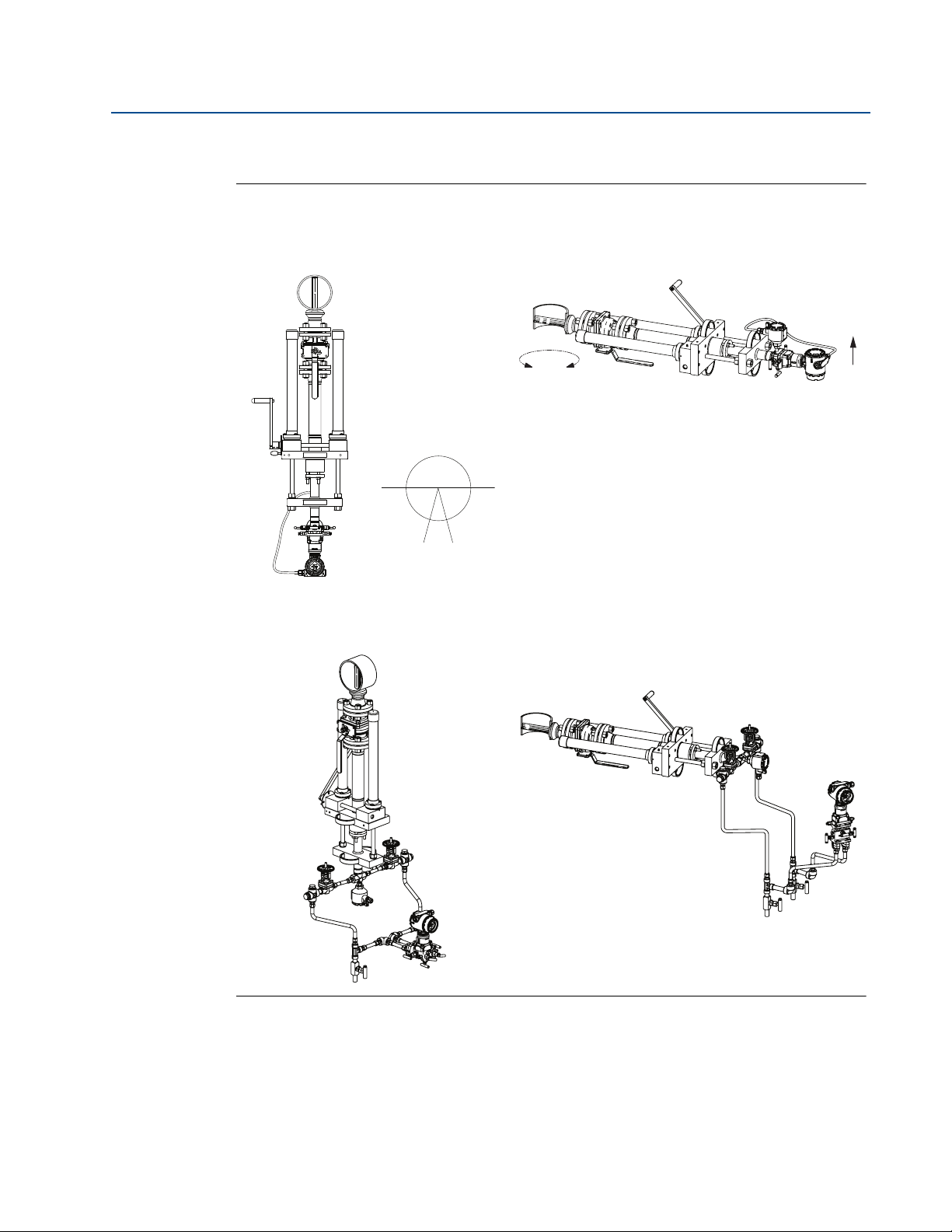
2.5.6 Flowmeter orientation
Liquid
Due to the possibility of air getting trapped in the Annubar sensor, it should be located
according to Figure 2-7 for liquid applications. It should be mounted between 15° to 45° from
vertical down to ensure that air is vented from the Annubar sensor, and that sediment or solid
particles are not collected within the Annubar sensor.
For liquid applications, mount the side drain/vent valve upward to allow the gases to vent. In
vertical lines, the Annubar sensor can be installed in any position around the circumference of
the pipe, provided the vents are positioned properly for bleeding or venting. Vertical pipe
installations require more frequent bleeding or venting, depending on the location.
For a remote mounted transmitter, mount the transmitter below the process piping, adjust 10°
to 15° above direct vertical down. Route the impulse piping down to the transmitter and fill the
system with cool water through the two cross fittings.
Figure 2-7. Liquid Applications
Reference Manual
00809-0100-4809, Rev DA
Direct mount
45° 45°
Recommended
zone 30°
Horizontal liquid Vertical liquid
Recommended
30°
zone 30°
Remote mount
Horizontal liquid Vertical liquid
14
Installation
Page 23
Reference Manual
45° 45°
Recommended
zone 90°
00809-0100-4809, Rev DA
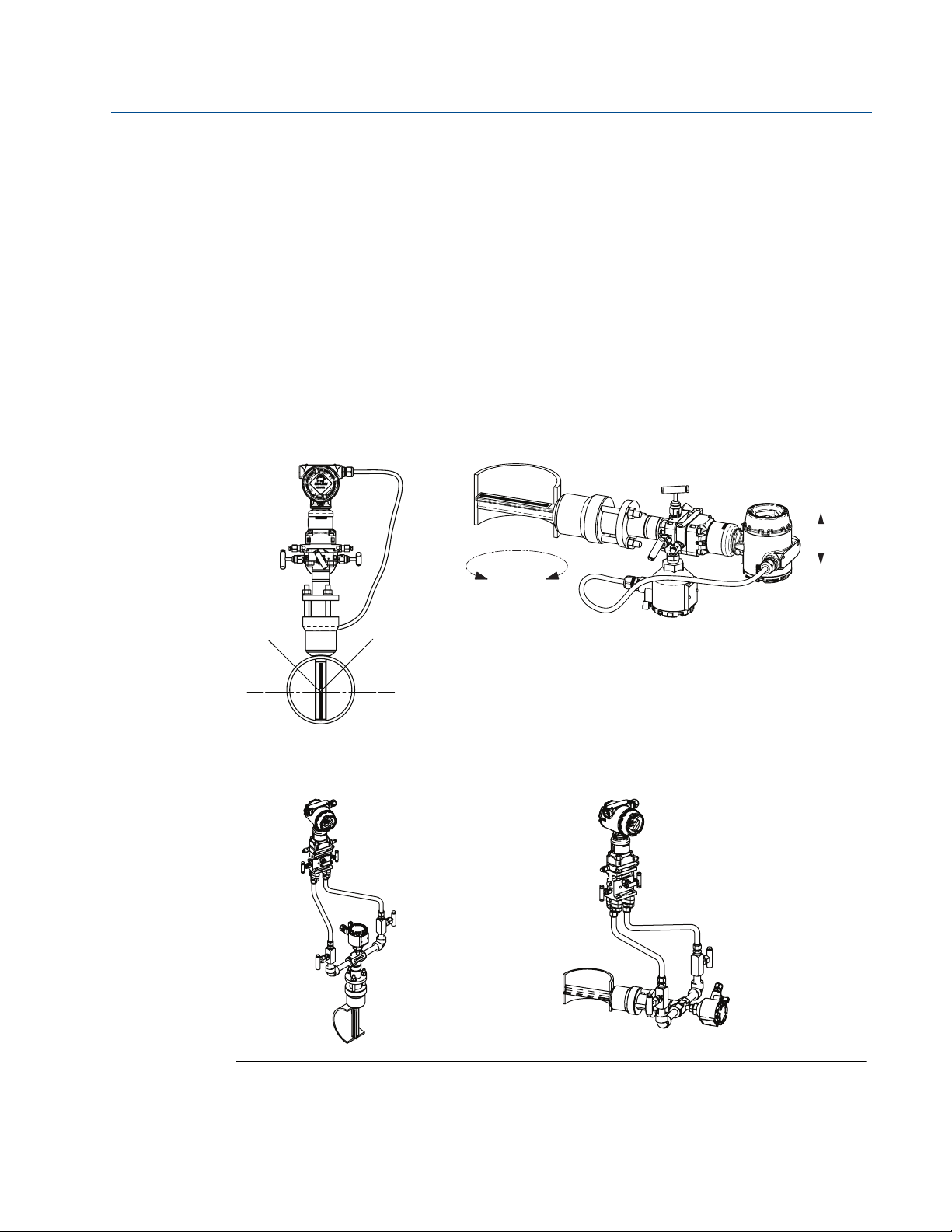
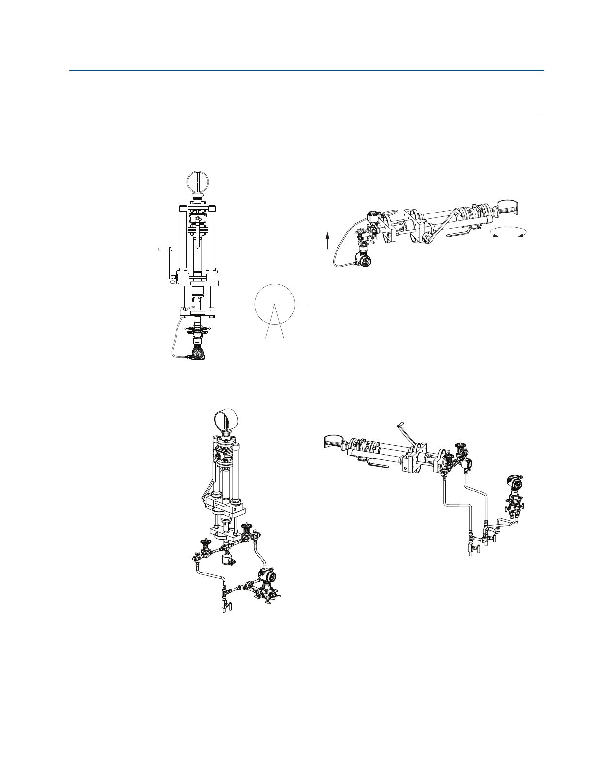
Gas
Figure 2-8 illustrates the recommended location of the flowmeter in gas applications. The
sensor should be located on the upper half of the pipe, at least 45° above the horizontal line.
For gas applications, mount the drain/vent valve downward to allow liquid to drain. In vertical
lines, the Annubar sensor can be installed in any position around the circumference of the pipe,
provided the vents are positioned properly for bleeding or venting. Vertical pipe installations
require more frequent bleeding or venting, depending on the location.
For a remote mounted transmitter, secure the transmitter above the Annubar sensor to prevent
condensible liquids from collecting in the impulse piping and the DP cell.
Figure 2-8. Gas Applications
Section 2: Installation
September 2015
Direct mount
Horizontal gas Vertical gas
360°
Remote mount
Horizontal gas Vertical gas
Flow
Installation
15
Page 24

Section 2: Installation
45° 45°
30°
Recommended
zone 30°
Recommended
zone 30°
September 2015
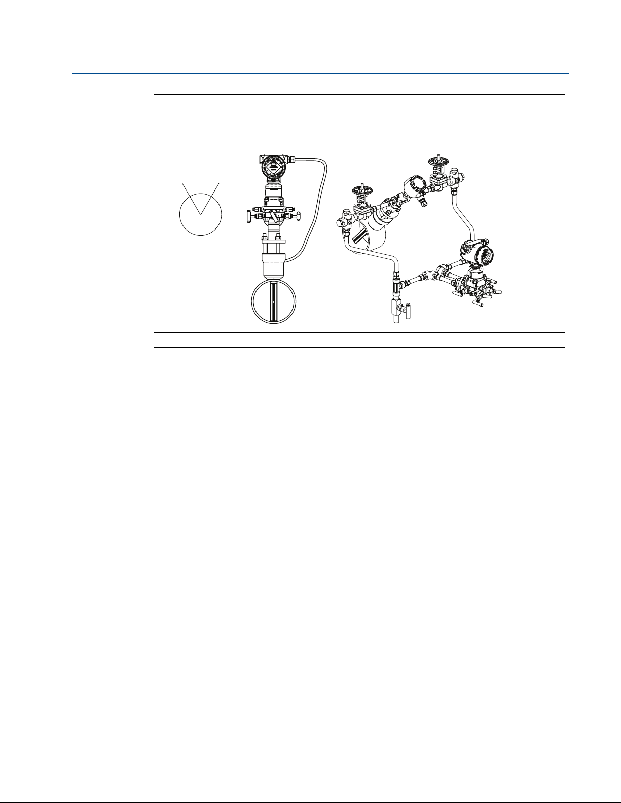
Steam
In steam applications, fill the lines with water to prevent the steam from contacting the
transmitter. Condensate chambers are not required because the volumetric displacement of the
transmitter is negligible.
For a remote mounted transmitter, mount the transmitter below the process piping, adjust to
10° to 15° above direct vertical down. Route the impulse piping down to the transmitter and fill
the system with cool water through the two cross fittings.
Top mounting for steam applications is an appropriate mounting option in many cases. Consult
Rosemount Customer Central for instructions regarding steam on top mounting.
Figure 2-9 illustrates the recommended location of the flowmeter in steam applications.
Figure 2-9. Steam Applications
Reference Manual
00809-0100-4809, Rev DA
Direct mount
Horizontal steam Vertical steam
Flow
Note: Downward flow is not recommended.
Remote mount
Horizontal steam Vertical steam
360°
16
Installation
Page 25
Reference Manual
00809-0100-4809, Rev DA
Section 2: Installation
September 2015
Figure 2-10. Top Mounting for Steam
(1)
Direct mount Remote mount
Horizontal top mounting for steam
Recommended zone
60° 60°
60°
Note
For wet steam, do not mount the flowmeter at the direct vertical position. Mounting at an angle
will avoid measurement inaccuracy due to water running along the bottom of the pipe.
2.5.7 Remote mounted transmitter
Instrument head connections differ between horizontal and vertical pipes. For horizontal lines,
the instrument connections are parallel to the pipe and for vertical lines, the instrument
connection are perpendicular.
Valves and fittings
Throughout the remote mounting process:
Use only valves, fittings, and pipe thread sealant compounds that are rated for the
service pipeline design pressure and temperature as specified in Appendix A:
Specifications and Reference Data.
Verify that all connections are tight and that all instrument valves are fully closed.
Verify that the Annubar sensor is properly oriented for the intended type of service:
liquid, gas, or steam (see “Flowmeter orientation” on page 14).
Impulse piping
Impulse piping connects a remote mounted transmitter to the Annubar sensor. Temperatures in
excess of 250 °F (121 °C) at the transmitter will damage electronic components; impulse piping
allows service flow temperatures to decrease to a point where the transmitter is no longer
vulnerable.
1. Consult with RCC to determine if this installation is right for your application.
Installation
17
Page 26

Section 2: Installation
September 2015
The following restrictions and recommendations apply to impulse piping location.
Piping used to connect the Annubar sensor and transmitter must be rated for
Impulse piping that runs horizontally must slope at least 1-in. per foot (83 mm/m).
With the Annubar mounted below the pipe, impulse piping must slope downwards
With the Annubar sensor mounted above the pipe, impulse piping must slope up
For applications where the pipeline temperature is below 250 °F (121 °C), the impulse
For applications where pipeline temperature is above 250 °F (121 °C), the impulse
A minimum of
Outdoor installations for liquid, saturated gas, or steam service may require insulation
Reference Manual
00809-0100-4809, Rev DA
continuous operation at the pipeline-designed pressure and temperature.
(toward the transmitter) for liquid and steam applications.
(toward from the transmitter) for gas applications.
piping should be as short as possible to minimize flow temperature changes. Insulation
may be required.
piping should have a minimum length of 1-ft. (0.30 m) for every 100 °F (38 °C) over
250 °F (121 °C), which is the maximum operating transmitter temperature. Impulse
piping must be uninsulated to reduce fluid temperature. All threaded connections
should be checked after the system comes up to temperature, because connections
may be loosened by the expansion and contraction caused by temperature changes.
1
/2-in. (12mm) outer diameter (OD) stainless steel tubing with a wall
thickness of at least 0.035-in. is recommended.
and heat tracing to prevent freezing.
For installations where the transmitter is more than 6-ft. (1.8m) from the Annubar
sensor, the high and low impulse piping must be run together to maintain equal
temperature. They must be supported to prevent sagging and vibration.
Threaded pipe fittings are not recommended because they create voids where air can
become entrapped and have more possibilities for leakage.
Run impulse piping in protected areas or against walls or ceilings. If the impulse piping
is run across the floor, ensure that it is protected with coverings or kick plates. Do not
locate the impulse piping near high temperature piping or equipment.
Use an appropriate pipe sealing compound rated for the service temperature on all
threaded connections. When making threaded connections between stainless steel
fittings, Loctite
®
PST® Sealant is recommended.
18
Installation
Page 27
Reference Manual
00809-0100-4809, Rev DA
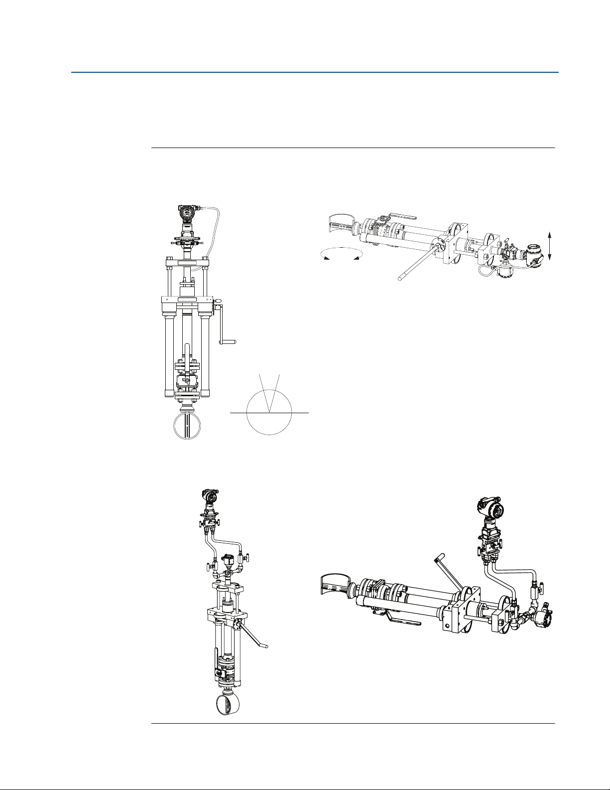
2.5.8 Flo-Tap models
Gas
Figure 2-11. Gas Service
Horizontal gas Vertical gas
Section 2: Installation
September 2015
Direct mount
360°
Flow
Recommended zone
30°
Remote mount
Horizontal gas Vertical gas
Installation
19
Page 28
Section 2: Installation
360°
Flow
Note: Downward flow is not recommended.
September 2015
Liquid
Figure 2-12. Liquid Service
Reference Manual
00809-0100-4809, Rev DA
Direct mount
Horizontal liquid Vertical liquid
30°
Recommended zone
Remote mount
Horizontal liquid Vertical liquid
20
Installation
Page 29
Reference Manual
360°
Flow
Note: Downward flow is not recommended.
00809-0100-4809, Rev DA
Steam
Figure 2-13. Steam
Section 2: Installation
September 2015
Direct mount
Horizontal steam Vertical steam
30°
Recommended zone
Remote mount
Horizontal steam Vertical steam
Installation
21
Page 30
Section 2: Installation
A
F
G
H
I
J
K
L
E
D
C
B
September 2015
Reference Manual
00809-0100-4809, Rev DA
2.6 Installation
This manual contains the horizontal and vertical installation procedures for the Pak-Lok,
Flanged, Flange-Lok, Threaded Flo-Tap, Flanged Flo-tap, and Main Steam Annubar sensor
models. For installation of the Compact Annubar Flowmeters, see Reference Manual (document
number 00809-0100-4810).
2.6.1 Pak-Lok Annubar sensor type (for 485 Annubar Flowmeters)
Figure 2-14 identifies the components of the Pak-Lok assembly.
Figure 2-14. Components
Transmitter and housing are shown for clarity purposes – only supplied if ordered.
A. Direct mount transmitter connection with valves
B. Nuts
C. Follower
D. Packing rings (3)
E. Studs
F. Transmitter
G. Coplanar flange with drain vents
H. O-rings (2)
I. Compression plate
J. Retaining ring
K. 485 Annubar sensor
L. Pak-Lok body
22
Installation
Page 31

Reference Manual
P/N: 28-109001-922 Rev. AC
Drill to Hole Size
Note: Drill the hole 180° from
the first hole for oppositeside support models.
Drill the appropriate diameter
hole through the pipe wall.
00809-0100-4809, Rev DA
Step 1: Determine the proper orientation
Refer to “Mounting” on page 8 for straight run requirements and orientation information.
Step 2: Drill a hole into the pipe
1. Determine the drill hole size based on the sensor size of sensor width.
2. Determine the sensor size based on the width of the Annubar sensor. See Ta b l e 2 -3 .
3. From the previous steps, select the location to drill the hole.
4. Determine the diameter of the hole to be drilled according to the specifications in
Section 2: Installation
September 2015
Ta bl e 2 - 3 and drill the hole with a hole saw or drill. Do not torch cut the hole.
Table 2-3. 485 Sensor Size/Hole Diameter Chart
Sensor size Sensor width Hole diameter
1
2
3
0.590-in.
(14.99 mm)
1.060-in.
(26.92 mm)
1.935-in.
(49.15 mm)
3
/4-in.
(19 mm)
15/16-in.
(34 mm)
21/2-in.
(64 mm)
+ 1/32-in. (0.8 mm)
– 0.00
+ 1/16-in. (1.6 mm)
– 0.00
+ 1/16-in. (1.6 mm)
– 0.00
5. If opposite-side support coupling is supplied, a second identically sized hole must be
drilled opposite the first hole so that the sensor can pass completely through the pipe.
(To determine an opposite-side support model, measure the distance from the tip of
the first slot or hole. If the distance is greater than 1-in. (25.4 mm), it is the
opposite-side model.) To drill the second hole, follow these steps:
a. Measure the pipe circumference with a pipe tape, soft wire, or string (for the most
accurate measurement the pipe tape needs to be perpendicular to the axis of flow).
b. Divide the measured circumference by two to determine the location of the second
hole.
c. Re-wrap the pipe tape, soft wire, or string from the center of the first hole. Then, using
the number calculated in the preceding step, mark the center of what will become the
second hole.
d. Using the diameter determined from Tab l e 2 - 3, drill the hole into the pipe with a hole
saw or drill. Do not torch cut the hole.
6. Deburr the drilled hole(s) on the inside of the pipe.
Installation
23
Page 32

Section 2: Installation
Serial No. Date
Model
Customer Tag
Pipe I.D. Wall
Max. Allow FlowRate
Max. Insert/Retract Flow
Max. Press. @ Temp
Span (20mA)
00-370000-2X1 Rev. AC
September 2015
Step 3: Weld the mounting hardware
Reference Manual
00809-0100-4809, Rev DA
1. Center the Pak-Lok body over the mounting hole, gap 1/16-in. (1.5 mm) and place four
1
/4-in. (6 mm) tack welds at 90° increments.
2. Check alignment of the Pak-Lok body both parallel and perpendicular to the axis of
flow. If alignment of mounting is within tolerances (see Figure 2-15), finish weld per
local codes. If alignment is outside of specified tolerance, make adjustments prior to
finish weld.
Figure 2-15. Alignment
LMH
A
A. Tack welds
3. If opposite side support is being used, center the fitting for the opposite side support
over the opposite side hole, gap
1
/16-in. (1.5 mm) and place four 1/4-in. (6 mm) tack
welds at 90° increments. Insert the sensor into the mounting hardware. Verify that the
tip of the bar is centered in the opposite side fitting and verify that the plug will fit
around bar. If the bar is centered in the fitting and plug fits around the bar, finish weld
per local codes. If the alignment of the bar does not allow enough clearance to insert
the opposite side plug, make the necessary adjustments prior to making the finish
weld.
24
4. To avoid serious burns, allow the mounting hardware to cool before continuing.
Step 4: Insert Annubar sensor
After the mounting hardware has cooled, use the following steps for installation.
1. Thread studs into the Pak-Lok body.
2. To ensure the flowmeter contacts the opposite side wall, mark the tip of the sensor with
a marker. (Do not mark if the sensor was ordered with special-cleaned option code P2 or
PA. )
3. Insert the flowmeter into the Pak-lok body until the sensor tip contacts the pipe wall (or
support plug). Rotate the flowmeter back and forth.
4. Remove the flowmeter.
Installation
Page 33

Reference Manual
00809-0100-4809, Rev DA
5. Verify the sensor tip made contact with the pipe wall by removing the pipe and
6. Align the flow arrow with the direction of flow. Re-insert the flowmeter into the Pak-Lok
7. Push the packing ring into the Pak-Lok body and against the weld lock ring. Repeat this
Figure 2-16. Packing Ring Detail
Section 2: Installation
September 2015
ensuring that some of the marker has been rubbed off. For special-cleaned Annubar
sensors, look for wear marks on the tip. If the tip did not touch the wall, verify pipe
dimensions and the height of mounting body from the outer diameter of the pipe and
re-insert.
body and install the first packing ring on the sensor between the lock ring and the
packing follower. Take care not to damage the split packing rings.
process for the two remaining rings, alternating the location of the packing ring split by
180°.
A
B
C
A. Retaining ring
B. Compression plate
C. Follower
D. Packing rings (3)
D
1. Install the first Packing Ring underneath the Follower.
2. Use the Follower and the Compression Plate to compress
the first Packing Ring against the Retaining Ring.
3. Install the second Packing Ring underneath the Follower.
Alternate packing ring splits by 120 degrees to each other.
4. Use the Follower and the Compression Plate to compress
the second Packing Ring against the first Packing Ring.
5. Install the third Packing Ring underneath the Follower.
6. Use the Follower and the Compression Plate to compress
the third Packing Ring against the second Packing Ring.
Installation
25
Page 34

Section 2: Installation
September 2015
8. Tighten the nuts onto the studs:
Reference Manual
00809-0100-4809, Rev DA
Place the included split-ring lock washer between each of the nuts and the
compression plate. Give each nut one half (
1
/2) turn in succession until the split-ring
lock washer is flat between the nut and the compression plate.
Sensor size Tor qu e
1 40-in./lb (4.52 Nm)
2 100-in./lb (11.30 Nm)
3 250-in./lb (28.25 Nm)
Inspect the unit for leakage; if any exists, tighten the nuts in one-quarter (
1
/4) turn
increments until there is no leakage.
Note
On sensor size (1), failure to use the split-ring lock washers, improper washer orientation, or
over-tightening the nuts may result in damage to the flowmeter.
Figure 2-17. Split-Ring Lock Washer Orientation
Before Tightening After Tightening
A
B
C
D
A. Stud
B. Nut
C. Split ring lock washer
D. Compression plate
Note
Pak-Lok sealing mechanisms generate significant force at the point where the sensor contacts
the opposite pipe wall. Caution needs to be exercised on thin-walled piping (ANSI Schedule 10
and below) to avoid damage to the pipe.
26
Installation
Page 35

Reference Manual
00809-0100-4809, Rev DA
Figure 2-18. Complete Installation of Pak-Lok
Section 2: Installation
September 2015
A
B
CD
A. Gap
B. Weld ring
C. Packing rings (3)
D. Follower
Figure 2-18 shows a view of the Pak-Lok Annubar sensor when installation is completed. Please
note that there should be a gap between the Pak-Lok Body and the Weld Ring.
Step 5: Mount the transmitter
Direct mount head
With valves
Place PTFE O-rings into grooves on the face of head.
Align the high side of the transmitter to the high side of the probe (“Hi” is stamped on
the side of the head) and install.
Tighten the nuts in a cross pattern to 400 in-lb. (45 N-m).
Without valves
Place PTFE O-rings into grooves on the face of head.
To install a manifold, orient the equalizer valve or valves so they are easily accessible.
Install manifold with the smooth face mating to the face of the head. Tighten in cross
pattern to a torque of 400 in-lb. (45 N-m).
Place PTFE O-rings into grooves on the face of the manifold.
Installation
Align the high side of the transmitter to the high side of the probe (“Hi” is stamped on
the side of the head) and install.
Tighten the nuts in a cross pattern to 400 in-lb. (45 N-m).
27
Page 36

Section 2: Installation
September 2015
Reference Manual
00809-0100-4809, Rev DA
2.6.2 Flanged with opposite side support Annubar sensor type
(for 485 and 585 Annubar Flowmeters)
Figure 2-19 identifies the components of the Flanged assembly.
Figure 2-19. Components
G
H
A
B
I
C
D
E
F
Transmitter and housing are shown for clarity purposes – only supplied if ordered.
A. O-rings (2)
B. Direct mount transmitter connection with valves
C. Studs
D. Gasket
E. Nuts
F. Opposites side support
J
K
G. Transmitter
H. Coplanar flange with drain vents
I. Sensor flange
J. Mounting flange assembly
K. 485 Annubar sensor
28
Installation
Page 37

Reference Manual
Drill the appropriate diameter
hole through the pipe wall.
Note: Drill the hole 180° from
the first hole for oppositeside support models.
Drill the appropriate diameter
hole through the pipe wall.
Note: Drill the hole 180° from
the first hole for oppositeside support models.
00809-0100-4809, Rev DA
Step 1: Determine the proper orientation
Refer to “Mounting” on page 8 for straight run requirements and orientation information.
Step 2: Drill a hole into the pipe
1. Determine the drill hole size based on the Sensor Size of Sensor Width.
2. Depressurize and drain the pipe.
3. From the previous steps, select the location to drill the hole.
4. Determine the diameter of the hole to be drilled according to the specifications in
Table 2-4. 485 Sensor Size/Hole Diameter Chart
Ta bl e 2 - 4 and drill the hole with a hole saw or a drill. Do not torch cut the hole.
Sensor size Sensor width Hole diameter
1
2
3
0.590-in.
(14.99 mm)
1.060-in.
(26.92 mm)
1.935-in.
(49.15 mm)
3
/4-in.
(19 mm)
15/16-in.
(34 mm)
21/2-in.
(64 mm)
1
/32-in. (0.8 mm)
+
– 0.00
+ 1/16-in. (1.6 mm)
– 0.00
1
/16-in. (1.6 mm)
+
– 0.00
Section 2: Installation
September 2015
Table 2-5. 585 Sensor Size/Hole Diameter Chart
Sensor size Sensor width Hole diameter
1
/32-in. (0,8 mm)
+
– 0.00
+ 1/16-in. (1,6 mm)
– 0.00
1
/16-in. (1,6 mm)
11
22
44
7
0.80-in.
(20.32 mm)
1.20-in.
(30.48 mm)
2.30-in. 2
/8-in.
(23 mm)
15/16-in.
(34 mm)
1
/2-in. +
(58.42 mm) (64 mm) – 0.00
5. If opposite-side support coupling is supplied, a second identically sized hole must be
drilled opposite the first hole so that the sensor can pass completely through the pipe.
To drill the second hole, follow these steps:
a. Measure the pipe circumference with a pipe tape, soft wire, or string (for the most
accurate measurement the pipe tape needs to be perpendicular to the axis of flow).
b. Divide the measured circumference by two to determine the location of the second
hole.
c. Re-wrap the pipe tape, soft wire, or string from the center of the first hole. Then,
using the number calculated in the preceding step, mark the center of what will
become the second hole.
d. Using the diameter determined from Ta b l e 2 -4 , drill the hole into the pipe with a
hole saw or drill. Do not torch cut the hole.
Installation
6. Deburr the drilled holes on the inside of the pipe.
29
Page 38

Section 2: Installation
September 2015
Step 3: Assemble and check fit-up
For accurate measurement, use the following steps to ensure that Ports A and B are equal
distances from the inside walls of the pipe.
1. Assemble the Annubar sensor to the mounting hardware with the gaskets and bolts.
2. Hand tighten the bolts just enough to hold the position of the sensor centered in the
Reference Manual
00809-0100-4809, Rev DA
mounting hardware.
3. Measure the distance from the high point of the weldolet to the first sensing hole, port
B, then subtract
1
/16-in. (1.6 mm).
4. Measure the distance from the end of the transferred length in Step 3 to the last sensing
hole, port A.
5. Compare the numbers obtained in Step 3 and 4.
Small discrepancies can be compensated for with the fit-up of the mounting hardware. Large
discrepancies may cause installation problems or error.
Figure 2-20. Fit-Up Check for Annubar Sensor with Opposite Side Support
B
C
E
30
A
A. The same within 1/8-in. (3 mm)
B. ODF
C. Port B
D
D. Port A
E. Pipe outside diameter
Installation
Page 39

Reference Manual
00809-0100-4809, Rev DA
Step 4: Weld the mounting hardware
1. Center the Flanged body over the mounting hole, gap 1/16-in. (1.5 mm) and measure the
Table 2-6. 485 and 585 Flange Sizes and ODF per Sensor Size
Section 2: Installation
September 2015
distance from the outside diameter of the pipe to the face of the flange. Compare this
to the table below and adjust the gap as necessary.
485 Sensor
size
1 11
585 Sensor
size
Flange
type
A
R
D
Pressure
class
1 11/2-in. 150# RF 3.88 (98.6)
3 11/2-in. 300# RF 4.13 (104.9)
6 11/2-in. 600# RF 4.44 (112.8)
N/9 11/2-in. 900# RF 4.94 (125.5)
F 11/2-in. 1500# RF 4.94 (125.5)
T 11/2-in. 2500# RF 6.76 (171.7)
1 11/2-in. 150# RTJ 4.06 (103.1)
3 11/2-in. 300# RTJ 4.31 (109.5)
6 11/2-in. 600# RTJ 4.44 (112.8)
N/9 11/2-in. 900# RTJ 4.94 (125.5)
F 11/2-in. 1500# RTJ 4.94 (125.5)
T 11/2-in. 2500# RTJ 6.81 (173.0)
1 DN40 PN16 RF 3.21 (81.5)
3 DN40 PN40 RF 3.21 (81.5)
6 DN40 PN100 RF 3.88 (98.6)
1 2.0-in. 150# RF 4.13 (104.9)
3 2.0-in. 300# RF 4.38 (111.3)
Flange size/
rating/type
ODF in.
(mm)
(1)
Installation
2 22
A
R
D
6 2.0-in. 600# RF 4.75 (120.7)
N/9 2.0-in. 900# RF 5.88 (149.4)
F 2.0-in. 1500# RF 5.88 (149.4)
T 3.0-in. 2500# RF 9.88 (251.0)
1 2.0-in. 150# RTJ 4.31 (119.5)
3 2.0-in. 300# RTJ 4.63 (117.6)
6 2.0-in. 600# RTJ 4.81 (122.2)
N 2.0-in. 900# RTJ 5.94 (150.9)
F 2.0-in. 1500# RTJ 5.94 (150.9)
T 3.0-in. 2500# RTJ 10.00 (254.0)
1 DN50 PN16 RF 3.40 (86.4)
3 DN50 PN40 RF 3.52 (89.4)
6 DN50 PN100 RF 4.30 (109.5)
31
Page 40

Section 2: Installation
September 2015
Table 2-6. 485 and 585 Flange Sizes and ODF per Sensor Size
Reference Manual
00809-0100-4809, Rev DA
485 Sensor
size
3 44
1. Tolerances for the ODF dimension above a 10-in. (254 mm) line size is ±0.060-in. (1,6 mm). Below 10-in. (254 mm) line size is
±0.030-in. (0,8 mm).
585 Sensor
size
Flange
type
A
R
D
Pressure
class
1 3.0-in. 150# RF 4.63 (117.6)
3 3.0-in. 300# RF 5.00 (127.0)
6 3.0-in. 600# RF 5.38 (136.7)
N/9 4.0-in. 900# RF 8.19 (208.0)
F 4.0-in. 1500# RF 8.56 (217.4)
T 4.0-in. 2500# RF 11.19 (284.2)
1 3.0-in. 150# RTJ 4.81 (122.2)
3 3.0-in. 300# RTJ 5.25 (133.4)
6 3.0-in. 600# RTJ 5.44 (138.2)
N/9 4.0-in. 900# RTJ 8.25 (209.6)
F 4.0-in. 1500# RTJ 8.63 (219.2)
T 4.0-in. 2500# RTJ 11.38 (289.1)
1 DN80 PN16 RF 3.85 (97.8)
3 DN80 PN40 RF 4.16 (105.7)
6 DN80 PN100 RF 4.95 (125.7)
Flange size/
rating/type
ODF in.
(mm)
(1)
1
2. Place four
/4-in. (6-mm) tack welds at 90° increments. Check alignment of the
mounting both parallel and perpendicular to the axis of flow (see Figure 2-21). If
alignment of the mounting is within tolerances, finish weld per local codes. If alignment
is outside of specified tolerance, make adjustments prior to making the finish weld.
Figure 2-21. Alignment
ODF
A
A. Tack welds
3. Center the fitting for the opposite side support over the opposite side hole, gap 1/16-in.
(1.5 mm) and place four
1
/4-in. (0.5 mm) tack welds at 90° increments. Insert the sensor
into the mounting hardware. Verify that the tip of the bar is centered in the opposite
side fitting and that the plug will fit around bar. If the sensor is centered in the fitting
and plug fits around the sensor, finish weld per local codes. If alignment of the sensor
does not allow enough clearance to insert the opposite side plug, make the necessary
adjustments prior to making the finish weld.
32
4. To avoid serious burns, allow the mounting hardware to cool before continuing.
Installation
Page 41

Reference Manual
00809-0100-4809, Rev DA
Step 5: Insert the Annubar sensor
1. If opposite side support is threaded, apply an appropriate thread sealing compound to
2. Align the flow arrow on the head with the direction of flow. Assemble the Annubar
Section 2: Installation
September 2015
the support plug threads and tighten until no leakage occurs.
sensor to the mounting flange using a gasket, bolts, and nuts.
3. If opposite side support is a socket weld fitting, insert the plug into the sockolet fitting
until the parts contact. Retract the plug
and apply fillet weld per local codes.
4. Tighten the nuts in a cross pattern to allow even compression of the gasket.
1
/16-in. (1.5 mm), remove the Annubar sensor
Step 6: Mount the transmitter
Direct mount head
With valves
1. Place PTFE O-rings into grooves on the face of head.
2. Align the high side of the transmitter to the high side of the probe (“Hi” is stamped on
the side of the head) and install.
3. Tighten the nuts in a cross pattern to 400 in-lb. (45 N-m).
Without valves
1. Place PTFE O-rings into grooves on the face of head.
2. To install a manifold, orient the equalizer valve or valves so they are easily accessible.
Install manifold with the smooth face mating to the face of the head. Tighten in cross
pattern to a torque of 400 in-lb. (45 N-m).
Installation
3. Place PTFE O-rings into grooves on the face of the manifold.
4. Align the high side of the transmitter to the high side of the probe (“Hi” is stamped on
the side of the head) and install.
5. Tighten the nuts in a cross pattern to 400 in-lb. (45 N-m).
33
Page 42

Section 2: Installation
September 2015
00809-0100-4809, Rev DA
2.6.3 Flange-Lok model (for 485 Annubar Flowmeters)
Figure 2-22 identifies the components of the Flange-Lok assembly.
Figure 2-22. Components
G
H
A
B
Reference Manual
C
I
D
E
J
F
K
L
M
Transmitter and housing are shown for clarity purposes – only supplied if ordered.
A. O-Rings (2)
B. Direct mount transmitter connection with valves
C. Follower
D. Packing rings (3)
E. Studs
F. G aske t
G. Transmitter
H. Coplanar flange with drain vents
I. Compression plate
J. Flange-Lok assembly
K. 485 Annubar sensor
L. Mounting flange assembly
M. Nuts
34
Installation
Page 43

Reference Manual
Drill the appropriate diameter hole
through the pipe wall.
Note: Drill the hole 180° from the
first hole for opposite-side support
models.
00809-0100-4809, Rev DA
Step 1: Determine the proper orientation
Refer to “Mounting” on page 8 for straight run requirements and orientation information.
Step 2: Drill a hole into the pipe
1. Determine the drill hole size based on the Sensor Size of Sensor Width.
2. De-pressurize and drain the pipe.
3. Select the location to drill the hole.
4. Determine the diameter of the hole to be drilled according to the specifications in
Table 2-7. Drill Hole into Pipe
Ta bl e 2 - 7 and drill the hole with a hole saw or a drill. Do not torch cut the hole.
Sensor size Sensor width Hole diameter
3
1
2
3
0.590-in.
(14.99 mm)
1.060-in.
(26.92 mm)
1.935-in.
(49.15 mm)
/4-in.
(19 mm)
15/16-in.
(34 mm)
1
/2-in.
2
(64 mm)
+ 1/32-in. (0.8 mm)
– 0.00
+ 1/16-in. (1.6 mm)
– 0.00
+ 1/16-in. (1.6 mm)
– 0.00
Section 2: Installation
September 2015
5. If opposite-side support coupling is supplied, a second identically sized hole must be
drilled opposite the first hole so that the sensor can pass completely through the pipe.
(To determine an opposite-side support model, measure the distance from the tip of
the first slot or hole. If the distance is greater than 1-in. (25.4 mm), it is the
opposite-side model.) To drill the second hole, follow these steps:
a. Measure the pipe circumference with a pipe tape, soft wire, or string (for the most
accurate measurement the pipe tape needs to be perpendicular to the axis of flow).
b. Divide the measured circumference by two to determine the location of the second
hole.
c. Re-wrap the pipe tape, soft wire, or string from the center of the first hole. Then,
using the number calculated in the preceding step, mark the center of what will
become the second hole.
d. Using the diameter determined from Ta b l e 2 -7 , drill the hole into the pipe with a
hole saw or drill. Do not torch cut the hole.
6. Deburr the drilled hole or holes on the inside of the pipe.
Installation
35
Page 44

Section 2: Installation
September 2015
Step 3: Weld the mounting hardware
1. Center the Flange-Lok body over the mounting hole, gap 1/16-in. (2 mm) and measure
Table 2-8. 485 and 585 Flange Sizes and ODF Per Sensor Size
Reference Manual
00809-0100-4809, Rev DA
the distance from the OD of the pipe to the face of the flange. Compare this to the table
below and adjust the gap as necessary.
485 Sensor size Flange type Pressure class
1 11/2-in. 150# RF 3.88 (98.6)
3 11/2-in. 300# RF 4.13 (104.9)
A
1
R
D
6 11/2-in. 600# RF 4.44 (112.8)
N 11/2-in. 900# RF 4.94 (125.5)
F 11/2-in. 1500# RF 4.94 (125.5)
T 11/2-in. 2500# RF 6.76 (171.7)
1 11/2-in. 150# RTJ 4.06 (103.1)
3 11/2-in. 300# RTJ 4.31 (109.5)
6 11/2-in. 600# RTJ 4.44 (112.8)
N 11/2-in. 900# RTJ 4.94 (125.5)
F 11/2-in. 1500# RTJ 4.94 (125.5)
T 11/2-in. 2500# RTJ 6.81 (173.0)
1 DN40 PN16 RF 3.21 (81.5)
3 DN40 PN40 RF 3.21 (81.5)
6 DN40 PN100 RF 3.88 (98.6)
1 2.0-in. 150# RF 4.13 (104.9)
Flange size/
rating/type
ODF in.
(1)
(mm)
36
3 2.0-in. 300# RF 4.38 (111.3)
A
2
R
D
6 2.0-in. 600# RF 4.75 (120.7)
N 2.0-in. 900# RF 5.88 (149.4)
F 2.0-in. 1500# RF 5.88 (149.4)
T 3.0-in. 2500# RF 9.88 (251.0)
1 2.0-in. 150# RTJ 4.31 (119.5)
3 2.0-in. 300# RTJ 4.63 (117.6)
6 2.0-in. 600# RTJ 4.81 (122.2)
N 2.0-in. 900# RTJ 5.94 (150.9)
F 2.0-in. 1500# RTJ 5.94 (150.9)
T 3.0-in. 2500# RTJ 10.00 (254.0)
1 DN50 PN16 RF 4.63 (117.6)
3 DN50 PN40 RF 5.00 (127.0)
6 DN50 PN100 RF 5.38 (136.7)
Installation
Page 45

Reference Manual
00809-0100-4809, Rev DA
Table 2-8. 485 and 585 Flange Sizes and ODF Per Sensor Size
Section 2: Installation
September 2015
485 Sensor size Flange type Pressure class
1 3.0-in. 150# RF 4.63 (117.5)
A
3
1. Tolerances for the ODF dimension above a 10-in. (254 mm) line size is ±0.060-in. (1,6 mm). Below 10-in. (254 mm) line size is
±0.030-in. (0,8 mm).
2. Place four
1
/4-in. (6-mm) tack welds at 90° increments. Check alignment of the
R
D
3 3.0-in. 300# RF 5.00 (126.9)
6 3.0-in. 600# RF 5.38 (136.6)
1 3.0-in. 150# RTJ 4.81 (122.2)
3 3.0-in. 300# RTJ 5.25 (133.4)
6 3.0-in. 600# RTJ 5.44 (138.2)
1 DN80 PN16 RF 3.85 (97.8)
3 DN80 PN40 RF 4.16 (105.7)
6 DN80 PN100 RF 4.95 (125.7)
Flange size/
rating/type
ODF in.
(mm)
mounting both parallel and perpendicular to the axis of flow (see Figure 2-23). If
alignment of the mounting is within tolerances, finish weld per local codes. If outside of
specified tolerance, make adjustments prior to making the finish weld.
Figure 2-23. Alignment
(1)
ODF
A
A. Tack welds
3. If opposite side support is being used, center the fitting for the opposite side support
over the opposite side hole, gap
1
/16-in. (1.5 mm) and place four 1/4-in. (6-mm) tack
welds at 90° increments. Insert the sensor into the mounting hardware. Verify that the
tip of the bar is centered in the opposite side fitting and that the plug will fit around the
bar. If the sensor is centered in the fitting and plug fits around the sensor, finish weld per
local codes. If alignment of the sensor does not allow enough clearance to insert the
opposite side plug, make the necessary adjustments prior to making the finish weld.
The Annubar sensor must be removed before welding or installing the opposite side
support plug.
4. To avoid serious burns, allow the mounting hardware to cool before continuing.
Installation
37
Page 46

Section 2: Installation
A
C
B
D
September 2015
Step 4: Insert into pipe
1. After the mounting hardware has cooled, use the following steps for installation.
2. Assemble the sensor flange to the mounting flange using gasket, studs, and nuts.
3. Tighten the nuts in a cross pattern to allow even compression of the gasket.
4. Thread studs into Flange-Lok body.
5. To ensure the flowmeter contacts the opposite side wall, mark the tip of the sensor with
6. Insert the flowmeter into the Flange-lok body until the sensor tip contacts the pipe wall
7. Remove the flowmeter.
8. Verify the sensor tip made contact with the pipe wall by ensuring that some of the
Reference Manual
00809-0100-4809, Rev DA
a marker. (Do not mark if the sensor was ordered with special-cleaned option code P2 or
PA. )
(or support plug), rotating back and forth.
marker has been rubbed off. For special-cleaned bars, look for wear marks on the tip. If
the tip did not touch the wall, verify pipe dimensions and the height of the mounting
body from the OD of the pipe and re-insert.
9. Re-insert the flowmeter into the Flange-Lok body and install the first packing ring on
the sensor between the lock ring and the packing follower. Take care not to damage the
split packing rings.
10. Push the packing ring into the Flange-Lok body and against the weld retaining ring.
Repeat this process for the two remaining rings, alternating the location of the packing
ring split by 180°.
Figure 2-24. Packing Ring Detail
A. Retaining ring
B. Compression plate
C. Follower
D. Packing rings (3)
38
Installation
Page 47

Reference Manual
00809-0100-4809, Rev DA
11. Tighten the nuts onto the studs:
Section 2: Installation
September 2015
a. Place the included split-ring lock washer between each of the nuts and the
compression plate. Give each nut one half (
1
/2) turn in succession until the split-ring
lock washer is flat between the nut and the compression plate. Torque is as follows:
Sensor size Tor qu e
1 40 in/lb (4.52 Nm)
2 100 in/lb (11.30 Nm)
3 250 in/lb (28.25 Nm)
1
b. Inspect the unit for leakage; if any exists, tighten the nuts in one-quarter (
/4) turn
increments until there is no leakage.
Note
On sensor size (1), failure to use the split-ring Lock washers, improper washer orientation, or
over-tightening the nuts may result in damage to the flowmeter.
Figure 2-25. Split-Ring Lock Washer Orientation
Before tightening After tightening
A
B
C
D
A. Stud
B. Nut
C. Split ring lock washer
D. Compression plate
Note
Flange-Lok sealing mechanisms generate significant force at the point where the sensor
contacts the opposite pipe wall. Caution needs to be exercised on thin-walled piping (ANSI
Schedule 10 and below) to avoid damage to the pipe.
Installation
39
Page 48

Section 2: Installation
A
C
BD
September 2015
Figure 2-26. Complete Installation of Flange-Lok
Reference Manual
00809-0100-4809, Rev DA
A. Gap
B. Packing rings (3)
C. Weld ring
D. Follower
Figure 2-26 shows a view of the Flange-Lok Annubar sensor when installation is completed.
Please note that there should be a gap between the Flange-Lok Body and the Weld Ring.
Step 5: Mount the transmitter
Direct mount head
With valves
1. Place PTFE O-rings into grooves on the face of head.
2. Align the high side of the transmitter to the high side of the Annubar sensor
(“Hi” is stamped on the side of the head) and install.
3. Tighten the nuts in a cross pattern to 400 in-lb. (45 N-m).
Without valves
1. Place PTFE O-rings into grooves on the face of head.
2. To install a manifold, orient the equalizer valve or valves so they are easily accessible.
Install manifold with the smooth face mating to the face of the head. Tighten in cross
pattern to a torque of 400 in-lb. (45 N-m).
40
3. Place PTFE O-rings into grooves on the face of the manifold.
4. Align the high side of the transmitter to the high side of the Annubar sensor
(“Hi” is stamped on the side of the head) and install.
5. Tighten the nuts in a cross pattern to 400 in-lb. (45 N-m).
Installation
Page 49

Reference Manual
A
B
C
D
E
F
G
H
I
J
L
K
M
N
O
00809-0100-4809, Rev DA
Section 2: Installation
2.6.4 Threaded Flo-tap (for 485 Annubar Flowmeter)
Figure 2-27 identifies the components of the Threaded Flo-Tap assembly.
Figure 2-27. Components
September 2015
Transmitter and housing are shown for clarity purposes – only supplied if ordered.
A. Transmitter
B. Coplanar flange with drain vents
C. Temperature sensor connection housing
D. Direct mount transmitter connection with valves
E. Head plate
F. Drive rods
G. Threaded pipe fitting
H. Guide nipple
I. Isolation valve
J. Cage nipple
K. Support plate
L. Packing gland
M. Packing
N. Follower
O. Compression plate
P. O- ri ng s (2)
Step 1: Determine the proper orientation
Refer to “Mounting” on page 8 for straight run requirements and orientation information.
Installation
41
Page 50

Section 2: Installation
LMH
A
September 2015
Step 2: Weld the mounting hardware
Note
Rosemount-supplied mounting includes critical alignment hardware that assists in the correct
drilling of the mounting hole. This significantly reduces problems encountered during insertion.
1. At the pre-determined position, place the threadolet on the pipe, gap
2. Check alignment of the mounting both parallel and perpendicular to the axis of flow. If
3. To avoid serious burns, allow mounting hardware to cool before continuing.
Figure 2-28. Alignment
Reference Manual
00809-0100-4809, Rev DA
1
/16 in. (16 mm)
and place four
1
/4-in. (6-mm) tack welds at 90° increments.
the mounting alignment is within tolerances, finish weld per local codes. If outside of
tolerances, make adjustments prior to making the finish weld.
A. Tack weld
Step 3: Install the isolation valve
1. Thread the guide nipple into the mounting.
2. Thread the isolation valve into the guide nipple, ensuring that the valve stem is
positioned so that when the Flo-Tap is installed, the insertion rods will straddle the pipe
and the valve handle will be centered between the rods (see Figure 2-29).
Note
Interference will occur if the valve is located inline with the insertion rods.
42
Installation
Page 51

Reference Manual
A
B
C
00809-0100-4809, Rev DA
Figure 2-29. Install the Isolation Valve
A. Isolation valve
Step 4: Mount the drilling machine and drill hole
Section 2: Installation
September 2015
A
Drilling machine is not provided with the assembly.
1. Determine the drill hole size based on the sensor size or sensor width.
2. Mount the drilling machine to the isolation valve.
3. Open the valve fully.
4. Drill the hole into the pipe wall in accordance with the instructions provided by the
drilling machine manufacturer.
5. Fully retract the drill beyond the valve.
Table 2-9. Sensor Size/Hole Diameter Chart
Sensor
size
1
2
3
Sensor
width
0.590-in.
(14.99 mm)
1.060-in.
(26.92 mm)
1.935-in.
(49.15 mm)
Hole diameter
3
/4-in.
(19 mm)
15/16-in.
(34 mm)
21/2-in.
(64 mm)
1
/32-in.
+
(0.8 mm)
– 0.00
+ 1/16-in.
(1.6 mm)
– 0.00
1
/16-in.
+
(1.6 mm)
– 0.00
A. Pressure drilling machine
B. Isolation valve is fully open when inserting drill
C. Isolation Valve is fully closed after withdrawing drill
Installation
43
Page 52

Section 2: Installation
September 2015
Step 5: Remove the drilling machine
Follow these steps to remove the drilling machine:
1. Verify the drill has been fully retracted past the valve.
2. Close the isolation valve to isolate the process.
3. Bleed drilling machine pressure and remove.
4. Check isolation valve and mounting for leakage.
Step 6: Mount the Annubar sensor
1. Install the complete Flo-Tap assembly (fully retracted) onto the isolation valve by
2. Rotate the Flo-Tap assembly until the flow arrow on the head aligns with the direction
3. Ensure the vent valves are closed before proceeding to the next step.
Reference Manual
00809-0100-4809, Rev DA
threading the close nipple into the valve using the proper thread sealant compound.
of flow in the pipe.
4. Quickly open and close the isolation valve to pressurize the Annubar sensor. Use
extreme caution if the flowing medium is steam or caustic.
5. Check the entire installation for leakage. Tighten as required to stop any connection
from leaking. Repeat steps 4 and 5 until there is no leakage.
a. If the Flo-tap comes equipped with the gear drive option, place the PVC protector
rod assembly over the drive rods and attach to the gear drive with the supplied
hardware.
Note
Flo-Tap Annubar sensors have the potential to carry a large amount of weight at a great distance
from the piping, necessitating external support. The support plate has threaded holes to assist
in supporting the Annubar sensor. Threaded holes (
3
/8 in.-16 UNC) are provided on the support
plate for external support.
Figure 2-30. Flo-Tap Installation
AA
44
B
A. Support plate
B. Isolation valve
Installation
Page 53

Reference Manual
00809-0100-4809, Rev DA
Step 7: Insert the Annubar sensor
Insert the sensor with one of the two drive options available – manual drive (M) or gear drive
(G).
Manual (not recommended for line sizes above 12-in. {300 mm])
1. Open the isolation valve fully.
2. Rotate drive nuts clockwise (as viewed from the top) as shown in Figure 2-30. The nuts
3. Continue this procedure until the tip of the probe firmly contacts the opposite side of
Section 2: Installation
September 2015
must be tightened alternately, about two turns at a time to prevent binding caused by
unequal loading.
the pipe.
a. The orange stripes are a visual indication of when the sensor is approaching the
opposite side wall.
b. As the orange stripe approaches the support plate, place a finger above the packing
gland while cranking.
c. Turn the drive nuts an additional
1
/4 to 1/2 turn to secure the sensor.
Gear drive (G)
1. Fully open the isolation valve.
2. Rotate the crank clockwise. If a power drill with an adapter is used, do not exceed 200
rpm.
a. Continue rotating the crank until the sensor firmly contacts the opposite side of the
pipe. The orange stripes are a visual indication of when the sensor is approaching
the opposite side wall.
b. As the orange stripes approach the support plate, remove the power drill and
continue cranking manually. Place a finger above the packing gland while cranking.
When the movement stops, the sensor is in contact with the opposite side wall.
c. Turn the handle an additional
3. Secure the drive by inserting the drive lock pin as shown in Figure 2-31.
Note
Do not place a finger above the packing gland for high temperature applications.
Figure 2-31. Insert Annubar Sensor
Manual drive (M) Gear drive (G)
1
/4 to 1/2 turn to secure the sensor.
Installation
A
B
A. Lock nuts
B. Drive nuts
C
C. Drive lock pin
45
Page 54

Section 2: Installation
September 2015
Step 8: Mount the transmitter
Direct mount head
With valves
1. Place PTFE O-rings into grooves on the Annubar sensor head.
2. Align the high side of the transmitter to the high side of the sensor
3. Tighten the nuts in a cross pattern to 400 in-lb. (45 N-m).
Without valves
1. Place PTFE O-rings into grooves on the Annubar sensor head.
2. To install a manifold, orient the equalizer valve or valves so they are easily accessible.
Reference Manual
00809-0100-4809, Rev DA
(“Hi” is stamped on the side of the head) and install.
Install manifold with the smooth face mating to the face of the head. Tighten in cross
pattern to a torque of 400 in-lb. (45 N-m).
3. Place PTFE O-rings into grooves on the face of the manifold.
4. Align the high side of the transmitter to the high side of the probe
(“Hi” is stamped on the side of the head) and install.
Tighten the nuts in a cross pattern to 400 in-lb. (45 N-m).
Step 9: Retract the Annubar sensor
Manual drive (M)
1. Retract by rotating the drive nuts counter-clockwise. The nuts must be turned
alternately, about two turns at a time, to prevent binding caused by unequal loading.
2. Continue this procedure until the rod end nuts are against the packing body
mechanism.
Gear drive (G)
1. Remove the drive lock pin.
2. Retract the sensor by rotating the crank counter-clockwise. If a power drill with an
adapter is used, do not exceed 200 rpm.
3. Retract until the rod end nuts are against the packing body mechanism.
46
Installation
Page 55

Reference Manual
M
P
00809-0100-4809, Rev DA
Section 2: Installation
September 2015
2.6.5 Flanged Flo-tap (for 485 and 585 Annubar Flowmeters)
Figure 2-32 identifies the components of the Flanged Flo-Tap assembly.
Figure 2-32. Components
A
B
O
N
L
K
J
I
H
C
D
E
F
G
Transmitter and housing are shown for clarity purposes – only supplied if ordered.
A. Coplanar flange with drain vents
B. Transmitter
C. O-rings (2)
D. Temperature sensor connection housing
E. Direct mount transmitter connection with valves
F. H ea d plate
G. Drive rods
H. Mounting flange assembly
I. Gasket
J. Isolation valve
K. Cage nipple
L. Support plate
M. Packing gland
N. Packing
O. Follower
P. Compression plate
Step 1: Determine the proper orientation
Refer to “Mounting” on page 8 for straight run requirements and orientation information.
Installation
47
Page 56

Section 2: Installation
September 2015
Step 2: Weld the mounting hardware
Note
Rosemount-supplied mounting includes critical alignment hardware that assists in the correct
drilling of the mounting hole. This significantly reduces problems encountered during insertion.
1. At the pre-determined position, place the flanged assembly on the pipe, gap
Table 2-10. 485 and 585 Flange Sizes and ODF per Sensor Size
Reference Manual
00809-0100-4809, Rev DA
1
/16 in. (1,6
mm) and measure the distance from the outside diameter of the pipe to the face of the
flange. Compare this to the chart below and adjust the gap as necessary.
48
485 Sensor
size
1 11
2 22
585 Sensor
size
Flange
type
A
R
D
A
R
D
Pressure
class
1 11/2-in. 150# RF 3.88 (98.6)
3 11/2-in. 300# RF 4.13 (104.9)
6 11/2-in. 600# RF 4.44 (112.8)
N 11/2-in. 900# RF 4.94 (125.5)
F 11/2-in. 1500# RF 4.94 (125.5)
T 11/2-in. 2500# RF 6.76 (171.7)
1 11/2-in. 150# RTJ 4.06 (103.1)
3 11/2-in. 300# RTJ 4.31 (109.5)
6 11/2-in. 600# RTJ 4.44 (112.8)
N 11/2-in. 900# RTJ 4.94 (125.5)
F 11/2-in. 1500# RTJ 4.94 (125.5)
T 11/2-in. 2500# RTJ 6.81 (173.0)
1 DN40 PN16 RF 3.21 (81.5)
3 DN40 PN40 RF 3.21 (81.5)
6 DN40 PN100 RF 3.88 (98.6)
1 2.0-in. 150# RF 4.13 (104.9)
3 2.0-in. 300# RF 4.38 (111.3)
6 2.0-in. 600# RF 4.75 (120.7)
N 2.0-in. 900# RF 5.88 (149.4)
F 2.0-in. 1500# RF 5.88 (149.4)
T 3.0-in. 2500# RF 9.88 (251.0)
1 2.0-in. 150# RTJ 4.31 (119.5)
3 2.0-in. 300# RTJ 4.63 (117.6)
6 2.0-in. 600# RTJ 4.81 (122.2)
N 2.0-in. 900# RTJ 5.94 (150.9)
F 2.0-in. 1500# RTJ 5.94 (150.9)
T 3.0-in. 2500# RTJ 10.00 (254.0)
1 DN50 PN16 RF 3.40 (86.4)
3 DN50 PN40 RF 3.52 (89.4)
6 DN50 PN100 RF 4.30 (109.5)
Flange size/
rating/type
ODF in.
(mm)
(1)
Installation
Page 57

Reference Manual
00809-0100-4809, Rev DA
Table 2-10. 485 and 585 Flange Sizes and ODF per Sensor Size
Section 2: Installation
September 2015
485 Sensor
size
3 44
1. Tolerances for the ODF dimension above a 10-in. (254 mm) line size is ±0.060-in. (1,6 mm). Below 10-in. (254 mm) line size is
±0.030-in. (0,8 mm).
585 Sensor
size
Flange
type
A
R
D
Pressure
class
1 3.0-in. 150# RF 4.63 (117.6)
3 3.0-in. 300# RF 5.00 (127.0)
6 3.0-in. 600# RF 5.38 (136.7)
N 4.0-in. 900# RF 8.19 (208.0)
F 4.0-in. 1500# RF 8.56 (217.4)
T 4.0-in. 2500# RF 11.19 (284.2)
1 3.0-in. 150# RTJ 4.81 (122.2)
3 3.0-in. 300# RTJ 5.25 (133.4)
6 3.0-in. 600# RTJ 5.44 (138.2)
N 4.0-in. 900# RTJ 8.25 (209.6)
F 4.0-in. 1500# RTJ 8.63 (219.2)
T 4.0-in. 2500# RTJ 11.38 (289.1)
1 DN80 PN16 RF 3.85 (97.8)
3 DN80 PN40 RF 4.16 (105.7)
6 DN80 PN100 RF 4.95 (125.7)
Flange size/
rating/type
ODF in.
(mm)
(1)
2. Place four
1
/4-in. (6-mm) tack welds at 90° increments. Check alignment of the
mounting both parallel and perpendicular to the axis of flow.
3. If the mounting alignment is within tolerances, finish weld per local codes. If outside of
tolerances, make adjustments prior to making the finish weld.
4. To avoid serious burns, allow the mounting hardware to cool before continuing.
Figure 2-33. Alignment
AODF
A. Tack weld
Step 3: Install the isolation valve
1. Position the isolation valve onto the mounting flange. Ensure the valve stem is
positioned so that when the Flo-Tap is installed, the insertion rods will straddle the pipe
and the valve handle will be centered between the rods (see Figure 2-34).
Installation
49
Page 58

Section 2: Installation
A
September 2015
Note
Interference will occur if the valve is located inline with the insertion rods.
2. Fasten the isolation valve to the mounting using gasket, bolts, and nuts.
Figure 2-34. Install Isolation Valve
A. Isolation valve
Reference Manual
00809-0100-4809, Rev DA
Step 4: Mount the drilling machine and drill hole
Drilling machine is not provided with the assembly.
1. Determine the drill hole size based on the sensor size or sensor width.
2. Mount the drilling machine to the isolation valve.
3. Open the valve fully.
4. Drill the hole into the pipe wall in accordance with the instructions provided by the
drilling machine manufacturer.
5. Retract the drill fully beyond the valve.
Table 2-11. 485 Drill Hole Sizes
Sensor
size
1
2
3
Sensor
width
0.590-in.
(14.99 mm)
1.060-in.
(26.92 mm)
1.935-in.
(49.15 mm)
Hole diameter
3
/4-in.
(19 mm)
15/16-in.
(34 mm)
1
2
/2-in.
(64 mm)
1
/32-in.
+
(0.8 mm)
– 0.00
+ 1/16-in.
(1.6 mm)
– 0.00
1
+
/16-in.
(1.6 mm)
– 0.00
A
C
B
A. Pressure drilling machine
B. Isolation valve is fully open when inserting drill
C. Isolation valve is fully closed after withdrawing drill
50
Installation
Page 59

Reference Manual
00809-0100-4809, Rev DA
Table 2-12. 585 Drill Hole Sizes
Section 2: Installation
September 2015
Sensor size Sensor width Hole diameter
11 0.8-in. (20.32 mm)
22 1.20-in. (30.48 mm) 15/16-in. (34 mm)
44 2.30-in. (58.42 mm) 21/2-in. (64 mm)
7
/8-in. (23 mm)
+ 1/32-in. (0,8 mm)
– 0.00
+ 1/16-in. (1,6 mm)
– 0.00
1
/16-in. (1,6 mm)
+
– 0.00
Step 5: Remove the drilling machine
1. Verify that the drill has been fully retracted past the valve.
2. Close the isolation valve to isolate the process.
3. Bleed drilling machine pressure and remove.
4. Check isolation valve and mounting for leakage.
Step 6: Mount the Annubar sensor
1. Align the flow arrow on the head with the direction of flow.
2. Use the supplied gaskets and flange bolts to fasten the Flo-Tap assembly to the isolation
valve.
3. Tighten the nuts in a cross pattern to compress the gasket evenly.
4. Ensure the vent valves are closed before proceeding.
5. Quickly open and close the isolation valve to pressurize the Annubar sensor. Use
extreme caution if the flowing medium is steam or caustic.
6. Check the entire installation for leakage. Tighten as required to stop any connection
from leaking. Repeat Steps 4 and 5 until there is no leakage.
a. If the Flo-tap comes equipped with the gear drive option, place the PVC protector rod
assembly over the drive rods and attach to the gear drive with the supplied hardware.
Note
Flo-Tap Annubar sensors have the potential to carry a large amount of weight at a great distance
from the piping, necessitating external support. The support plate has threaded holes to assist
in supporting the Annubar sensor. Threaded holes (
3
/8 in.-16 UNC) are provided on the support
plate for external support.
Installation
51
Page 60

Section 2: Installation
A
B
September 2015
Figure 2-35. Flo-Tap Installation
A. Support plate
B. Isolation valve
Reference Manual
00809-0100-4809, Rev DA
Step 7: Insert the Annubar sensor
Insert the sensor with one of the two drive options available – manual (M) or gear drive (G).
Manual (M) (not recommended for line size above 12-in. (300 mm))
1. Open the isolation valve fully.
2. Rotate drive nuts clockwise (as viewed from the top) as shown in Figure 2-35. The nuts
must be tightened alternately, about two turns at a time to prevent binding caused by
unequal loading.
3. Continue this procedure until the tip of the probe firmly contacts the opposite side of
the pipe.
a. The orange stripes are a visual indication of when the sensor is approaching the
opposite side wall.
b. As the orange stripe approaches the support plate, place a finger above the packing
gland while cranking.
c. Turn the drive nuts an additional
Gear drive (G)
1. Open the isolation valve fully.
2. Rotate the crank clockwise. If a power drill with an adapter is used, do not exceed 200
rpm.
1
/4 to 1/2 turn to secure the sensor.
a. Continue rotating the crank until the sensor firmly contacts the opposite side of the
pipe. The orange stripes are a visual indication of when the sensor is approaching the
opposite side wall.
52
Installation
Page 61

Reference Manual
A
B
00809-0100-4809, Rev DA
3. Secure the drive by inserting the drive lock pin as shown in Figure 2-36.
Figure 2-36. Insert Annubar Sensor
Section 2: Installation
September 2015
b. As the orange stripes approach the support plate, remove the power drill and continue
cranking manually. Place a finger above the packing gland while cranking. When
movement stops, the sensor is in contact with the opposite side wall.
1
c. Turn the handle an additional
/4 to 1/2 turn to secure the sensor.
Manual drive (M) Gear drive (G)
C
A. Lock nuts
B. Drive nuts
C. Drive lock pin
Step 8: Retract the Annubar sensor
Manual Drive (M)
1. Retract by rotating the drive nuts counter-clockwise. The nuts must be turned
alternately, about two turns at a time, to prevent binding caused by unequal loading.
2. Continue this procedure until the rod end nuts are against the packing body
mechanism.
Gear Drive (G)
1. Remove the drive lock pin.
2. Retract the sensor by rotating the crank counter-clockwise. If a power drill with an
adapter is used, do not exceed 200 rpm.
3. Retract until the rod end nuts are against the packing body mechanism.
Installation
53
Page 62

Section 2: Installation
September 2015
Step 9: Mount the transmitter
Direct mount head
With valves
1. Place PTFE O-rings into grooves on the face of head.
2. Align the high side of the transmitter to the high side of the sensor (“Hi” is stamped on
3. Tighten the nuts in a cross pattern to 400 in-lb. (45 N-m).
Without valves
1. Place PTFE O-rings into grooves on the face of head.
2. To install a manifold, orient the equalizer valve or valves so they are easily accessible.
Reference Manual
00809-0100-4809, Rev DA
the side of the head) and install.
Install manifold with the smooth face mating to the face of the head. Tighten in cross
pattern to a torque of 400 in-lb. (45 N-m).
3. Place PTFE O-rings into grooves on the face of the manifold.
4. Align the high side of the transmitter to the high side of the probe (“Hi” is stamped on
the side of the head) and install.
5. Tighten the nuts in a cross pattern to 400 in-lb. (45 N-m).
54
Installation
Page 63

Reference Manual
A
B
C
D
E
F
GH
I
J
K
L
00809-0100-4809, Rev DA
2.6.6 Main steam line (for 585 Annubar Flowmeters)
Figure 2-37 identifies the components of the Main Steam Annubar sensor assembly.
Figure 2-37. Components
Section 2: Installation
September 2015
A. Packing gland
B. Weldolet
C. Opposite side support cap
D. Packing gland nuts
E. Packing gland washers
F. Packing Gland Cover
Step 1: Determine the proper orientation
G. Locking nuts
H. Roll pins
I. Locking washers
J. Remote mount instrument connections
K. Locking rods
L. 585 sensor
Refer to “Mounting” on page 8 for straight run requirements and orientation information.
Step 2: Drill mounting hole into pipe
1. De-pressurize and drain the pipe.
2. At the predetermined position, drill the hole into the pipe wall in accordance with the
instructions provided by the drilling machine manufacturer. Drill 2.5-in. (64 mm) hole.
Drill hole has a tolerance of +
Installation
1
/16-in. or -0 in. (1,6 mm or -0 mm).
55
Page 64

Section 2: Installation
September 2015
3. After the hole is drilled, deburr the hole on the inside of the pipe.
4. A second identically sized hole must be drilled opposite the first hole so that the sensor
5. Deburr the drilled holes on the inside of the pipe.
Step 3: Weld the mounting hardware
Reference Manual
00809-0100-4809, Rev DA
can pass completely through the pipe. To drill the second hole, follow these steps:
a. Measure the pipe circumference with a pipe tape, soft wire, or string. (For the most
accurate measurement the pipe tape needs to be perpendicular to the axis of flow.)
b. Divide the measured circumference by two to determine the location of the second
hole.
c. Re-wrap the pipe tape, soft wire, or string from the center of the first hole. Then,
using the number calculated in the preceding step, mark the center of what will
become the second hole.
d. Using the diameter determined in Step 3, drill the hole into the pipe with a hole saw
or drill. Do not torch cut the hole.
An alignment bar is needed during the welding of the heavy wall weldolets to the steam
pipeline. The alignment bar can be ordered from Emerson
™
Process Management.
1. Weld the heavy wall weldolet to the packing gland assembly with a full
penetration-groove weld.
a. Place the alignment bar through the packing gland and the weldolet. The weldolet
will also have a bearing sleeve in it and it should be near the radius end of the
weldolet which will be the end welded to the pipe. Ensure the support plate is
attached to the packing gland before making the weld.
b. Tack weld the weldolet to the packing gland. Remove the alignment bar.
c. Weld the first pass. Recheck alignment with the alignment bar. Adjust alignment as
necessary. Do not allow the alignment bar to get too hot, as it will be difficult to
remove. Use it only briefly to check alignment between weld passes.
d. Complete remaining weld passes, using alignment bar to verify alignment several
times during the process. Emerson Process Management recommends the weld
thickness is equal to the base metal thickness.
2. Weld the weldolet and packing gland assembly to the pipe.
a. Place alignment bar back into the pipe, slide the weldolet and packing gland
assembly down the alignment bar, and let it rest on the pipe.
b. Ensure the 1
1
/8-in. (29 mm) holes in the support plate are perpendicular to the pipe
centerline within ± 3° for horizontal lines and parallel to the pipe centerline within ±
3° for vertical lines. This will ensure the impact and static holes will be in line with
the flow stream. See Figure 2-5 on page 10.
c. Tack weld the weldolet to the pipe. Check alignment. Remove the alignment bar
and weld the first pass. Emerson Process Management recommends using TIG
welding for the first two passes as a minimum. Experience has shown that welding
1
about
/2 to 2/3 of the weld using GTAW (TIG) and then using other weld processes
(GMAW, SMAW, FCAW) leads to lower chances of movement of the weldment
during welding.
56
Installation
Page 65

Reference Manual
00809-0100-4809, Rev DA
Note
It is very helpful to have two welders welding the assemblies to pipe, with one welder starting
180° from the other. This helps prevent movement of the fittings during the temperature
changes associated with welding.
3. Weld the opposite side weldolet to the pipe.
Section 2: Installation
September 2015
d. Check the alignment after the first pass. Remove the alignment bar and weld the
next pass. Recheck alignment.
e. Continue applying weld passes and rechecking alignment until welding is complete.
1
The fillet welds will be approximately 1
/8-in. (29 mm).
a. Slide the alignment bar through mounting and hole in top side of pipe and place the
opposite-side support weldolet over the end of the alignment bar.
b. Visually center the opposite-side weldolet over the hole. Tack weld the weldolet,
using tack bars or an equivalent method.
c. Weld the first pass and check alignment using the alignment bar and continue
welding. Check alignment frequently during welding. Adjust weldolet as you are
making tacks to keep aligned. Do not leave alignment bar in too long as it will heat
up and make it very difficult to remove.
d. When welding is complete, the alignment bar should slide freely through the
packing into the opposite-side weldolet.
e. Weld opposite end cap to weldolet using a full penetration groove weld.
4. Perform required heat treatment.
5. Reinstall 585 Main Steam Annubar sensor after heat treating and ensure the flow arrow
is pointing in the direction of flow.
Step 4: Insert the Annubar sensor
1. Place the packing into the packing gland with the two split rings (Garlock style
1303FEP) on the outside and the three Garlock Carbon/Graphite solid die-formed rings
on the inside. Make sure the splits in the outer packing are 180° apart.
Note
The packing gland and support plate will be shipped fully assembled.
2. Slide the 585 Annubar sensor through the packing and install the locking rods, nuts,
and lock washers. The dimension between the plates should be 11.0-in. (279 mm). See
Figure 2-38 on page 58. If there is visual access to the inside of the pipe, ensure that the
sensing holes are equally spaced from the inner diameter of the pipe.
3. Make the small adjustment (if necessary), then lock the 585 in place with the locking
rods, nuts, and lock washers. When installed, the 585 will have a dimension of 29.6-in.
(752 mm) from pipe OD to top of head.
4. The last thing to be done is to tighten the packing gland nuts to 25 to 30 ft-lbs. (34 to
41 N-m). See Figure 2-36.
Installation
57
Page 66

Section 2: Installation
A
September 2015
Figure 2-38. Tighten The Packing Gland Nuts
A. Packing gland nuts
Step 5: Mount the transmitter
Impulse piping that runs horizontally must slope downward at least one inch per foot
Impulse piping should have a minimum length of 1-ft. (0.3048 m) for every 100 °F
Reference Manual
00809-0100-4809, Rev DA
(83 mm/m).
(38 °C) temperature increase over 250 °F (121 °C).
a. Impulse piping must be non-insulated to reduce fluid temperature.
b. Any threaded connections should be checked after the system reaches the intended
temperature because connections may come loose with contraction and expansion
caused by temperature change.
Outdoor installations may require insulation and heat tracing to prevent freezing.
When impulse piping is longer than 6-f t. (1.8 m) the high and low impulse lines must be
positioned together to maintain equal temperature. They must be supported to
prevent sagging and vibration.
Impulse lines should be positioned in protected areas or against walls or ceilings. Use
appropriate pipe sealing compound rated for the service temperature on all threaded
connections. Do not place the impulse piping near high temperature piping or
equipment.
a. An instrument manifold is recommended for all installations. Manifolds allow an
operator to equalize the pressures prior to zeroing and isolates the process fluid
from the transmitter.
b. Use only valves and fittings rated for the design pressure and temperature (in some
cases the primary instrument valve may be supplied by Emerson Process
Management with the Annubar sensor).
c. Use a pipe thread sealant compound that is rated for use at the service temperature
and pressure for all valves and fittings.
d. Verify that all connections are tight and that all instrument valves are fully closed.
e. Verify that the sensor probe is properly oriented as per the submitted outline
drawings.
f. The piping used to connect the sensor probe and transmitter must be rated for
continuous operation at the pipeline-designed pressure and temperature. A
minimum of one-half inch (
thickness of at least
1
1
/2-in., 12 mm) O.D. stainless steel tubing with a wall
/16-in. (1,6 mm) is recommended.
58
Installation
Page 67

Reference Manual
00809-0100-4809, Rev DA
2.7 Wire the transmitter
See appropriate transmitter manual for bench configuration information.
Section 2: Installation
September 2015
Tra ns mitt er
Rosemount 3051S
MultiVariable Mass and
Energy Flow Transmitter
Rosemount 3051S Pressure
Transmitter
Rosemount 3095MV
MultiVariable Mass Flow
Transmitter
Rosemount 3051 Pressure
Transmitter
Rosemount 2051 Pressure
Transmitter
HART® document
number
00809-0100-4803 N/A N/A
00809-0100-4801 00809-0200-4801 N/A
00809-0100-4716 00809-0100-4716 N/A
00809-0100-4001 00809-0100-4774 00809-0100-4797
00809-0100-4101 00809-0200-4101 N/A
FOUNDATION Fieldbus™
document number
PROFIBUS®
document number
Do not connect the powered signal wiring to the test terminals. Power may damage the test
diode in the test connection.
Plug and seal unused conduit connections on the electronics housing to avoid moisture
accumulation in the terminal side of the housing. Excess moisture accumulation may damage
the electronics. If the connections are not sealed, the electronics should be remote mounted
with the electrical housing positioned downward for drainage. Wiring should be installed with a
drip loop and the bottom of the drip loop should be lower then the conduit connections and the
housing.
Inductive-based transient protectors, including the Rosemount 470 transient protector, can
adversely affect the output of the Annubar sensor. If transient protection is desired, install the
Transient Protection Terminal Block. Consult the factory for instructions.
2.7.1 Wiring diagrams
1. Remove the housing cover on the side marked FIELD TERMINALS. Do not remove the
instrument covers in explosive atmospheres when the circuit is live.
2. Connect the lead that originates at the positive side of the power supply to the terminal
marked “+” and the lead that originates at the negative side of the power supply to the
terminal marked “–.” Avoid contact with the leads and terminals.
Installation
59
Page 68

Section 2: Installation
September 2015
Reference Manual
00809-0100-4809, Rev DA
60
Installation
Page 69

Reference Manual
00809-0100-4809, Rev DA
Section 3 Commissioning
Safety messages . . . . . . . . . . . . . . . . . . . . . . . . . . . . . . . . . . . . . . . . . . . . . . . . . . . . . . . . . . . . page 61
Transmitter commissioning . . . . . . . . . . . . . . . . . . . . . . . . . . . . . . . . . . . . . . . . . . . . . . . . . . page 62
Commissioning the Annubar sensor . . . . . . . . . . . . . . . . . . . . . . . . . . . . . . . . . . . . . . . . . . . page 62
3.1 Safety messages
Instructions and procedures in this section may require special precautions to ensure the safety
of the personnel performing the operations. Refer to the following safety messages before
performing any operation in this section.
Section 3: Commissioning
September 2015
Explosions could result in death or serious injury.
Do not remove the transmitter cover in explosive atmospheres when the circuit is live.
Before connecting a Field Communicator in an explosive atmosphere, make sure the
instruments in the loop are installed in accordance with intrinsically safe or
non-incendive field wiring practices.
Verify the operating atmosphere of the transmitter is consistent with the appropriate
hazardous locations certifications.
Both transmitter covers must be fully engaged to meet explosion-proof requirements.
Failure to follow these installation guidelines could result in death or serious injury.
Make sure only qualified personnel perform the installation.
If the line is pressurized, serious injury or death could occur by opening valves.
Section 3 contains information that are suggested procedures only. The user must follow all
plant safety procedures for their process and location.
Commissioning
61
Page 70

Section 3: Commissioning
September 2015
3.2 Transmitter commissioning
See the appropriate transmitter manual for wiring and configuration instructions.
Table 3-1. Transmitter Manual Document Numbers
Reference Manual
00809-0100-4809, Rev DA
Tra ns mi tt er
Rosemount® 3051S
MultiVariable™ Mass and
Energy Flow Transmitter
Rosemount 3051S Pressure
Tr an sm i tt er
Rosemount 3095
MultiVariable Mass Flow
Tr an sm i tt er
Rosemount 3051 Pressure
Tr an sm i tt er
Rosemount 2051 Pressure
Tr an sm i tt er
HART® document
number
00809-0100-4803 N/A N/A
00809-0100-4801 00809-0200-4801 N/A
00809-0100-4716 00809-0100-4716 N/A
00809-0100-4001 00809-0100-4774 00809-0100-4797
00809-0100-4101 00809-0200-4101 N/A
FOUNDATION fieldbus™
document number
3.3 Commissioning the Annubar sensor
3.3.1 Direct mount transmitter
Prepare transmitter for service
Prior to commissioning the flowmeter, a zero trim procedure (or “dry zero”) should be
performed to eliminate any positional effects to the transmitter. Refer to Figure 3-1 and Figure
3-2 for valve designations.
PROFIBUS®
document number
62
1. Open first the equalizer valve(s) MEL and MEH or ME.
2. Close valves MH and ML.
3. Read the transmitter output. It should read within the range 3.98 mA to 4.02 mA. If the
output is outside of this range, perform a zero trim procedure as described in
transmitter manual (see Table 3-1 for transmitter manual document numbers).
“Calibrate out” line pressure effects
For applications with static pressures of 100 psi (6.9 bar) and higher, the DP sensor should be
zeroed for line pressure effects. The “zero” calibration procedure is affected by static pressure
and ambient temperature, but these effects can be minimized by zeroing the DP sensor at
normal operating conditions.
The effect of static pressure is calibrated out by exposing the transmitter to the line pressure
and performing a “zero” or wet calibration, as described below.
Although the line pressure effects are relatively small, they significantly affect the accuracy of
the Annubar sensor when used with low flows.
Commissioning
Page 71

Reference Manual
ML
DVL
ME
DVH
MH
00809-0100-4809, Rev DA
Periodic “zero” calibration and/or commissioning is recommended to maintain the accuracy of
Annubar sensor. The frequency of this type of maintenance should be established for each
individual application.
Liquid service 3-valve manifold
The following procedures assume the process pipe is pressurized to normal operating pressure
and should be followed to obtain a true zero at static or “pipe” pressure.
1. Open the high and low manifold valves MH and ML. Refer to Figure 3-1 for valve
2. Open the Equalizer valve ME.
3. Open the drain/vent valves on the transmitter DVH and DVL; bleed until no air is
4. Close both drain/vent valve DVH and DVL.
5. Close the low side manifold valve ML.
Section 3: Commissioning
September 2015
designations.
apparent in the liquid.
6. Check the transmitter zero by noting the output. If the signal reads outside of the range
3.98 mA to 4.02 mA then perform a zero trim procedure as described in the transmitter
manual.
7. After the zero trim, if the signal reads outside of the range 3.98 mA to 4.02 mA, repeat
Steps 1 - 6.
8. Close the Equalizer valve ME.
9. Open the low side valve ML and ensure that the high side valve MH is open.
10. The system is now operational.
Figure 3-1. Valve Identification for Direct Mounted Annubar Sensor Models with 3-Valve
Manifold
Commissioning
63
Page 72

Section 3: Commissioning
ML
MEL
DVL
MV
MH
MEH
DVH
September 2015
Liquid service 5-valve manifold
The following procedures assume the process pipe is pressurized to normal operating pressure
and should be followed to obtain a true zero at static or “pipe” pressure.
1. Open high and low manifold valves MH and ML. Refer to Figure 3-2 for valve
2. Open high side equalizer valve MEH.
3. Open low side equalizer valve MEL.
4. Open manifold vent MV; Bleed until no air is present in the liquid.
5. Close manifold vent MV.
6. Close low side manifold valve ML.
7. Check transmitter zero by noting the output. If the signal reads outside of the range
Reference Manual
00809-0100-4809, Rev DA
designations.
3.98 mA to 4.02 mA then perform a zero trim procedure as described in the transmitter
manual.
8. After the zero trim, if the signal reads outside the range 3.98 mA to 4.02 mA, repeat
Steps 1 - 6.
9. Close low side equalizer valve MEL.
10. Close high side equalizer valve MEH.
11. Open low side manifold valve ML and ensure high side manifold valve MEH is open.
12. The system is now operational.
Figure 3-2. Valve Identification for Direct Mounted Models with 5-Valve Manifold
64
Commissioning
Page 73

Reference Manual
00809-0100-4809, Rev DA
Gas service 3-valve manifold
The following procedures assume the process pipe is pressurized to normal operating pressure
and should be followed to obtain a true zero at static or “pipe” pressure.
1. Open the high and low manifold valves MH and ML. Refer to Figure 3-1 for valve
2. Open the Equalizer valve ME.
3. Open the drain/vent valves on the transmitter DVH and DVL; bleed to ensure that no
4. Close both drain/vent valve DVH and DVL.
5. Close the low side valve ML.
6. Check the transmitter zero by noting the output. If the signal reads outside of the range
7. After zero trim, if the signal reads outside of the range 3.98 mA to 4.02 mA, repeat
Section 3: Commissioning
September 2015
designations.
liquid is present.
3.98 mA to 4.02 mA, then perform a zero trim.
Steps 1 - 6.
8. Close the Equalizer valve ME.
9. Open the low side valve ML, ensure that the high side valve MH is open. The system is
now operational.
Gas service 5-valve manifold
The following procedures assume the process pipe is pressurized to normal operating pressure
and should be followed to obtain a true zero at static or “pipe” pressure.
1. Open high and low manifold valves MH and ML. Refer to Figure 3-2 for valve
designations.
2. Open high side equalizer valve MEH.
3. Open low side equalizer valve MEL.
4. Open manifold vent MV; Bleed until no liquid is present in the gas.
5. Close manifold vent MV.
6. Close low side manifold valve ML.
7. Check transmitter zero by noting the output. If the signal reads outside of the range
3.98 mA to 4.02 mA then, perform a zero trim procedure as described in the
transmitter manual.
Commissioning
8. After the zero trim, if the signal reads outside the range 3.98 mA to 4.02 mA, repeat
Steps 1 - 6.
9. Close low side equalizer valve MEL.
65
Page 74

Section 3: Commissioning
September 2015
10. Close high side equalizer valve MEH.
11. Open low side manifold valve ML and ensure high side manifold valve MEH is open.
12. The system is now operational.
Steam service (filling the water legs)
1. Ensure the steam line is depressurized with no steam.
2. Check the transmitter for a dry zero of 4 mA with no water loss.
3. Attach hose connection valve to high side vent DVH. See Figure 3-3.
4. Attach a water supply to the hose connection. The water supply should have a
5. Open the high and low manifold valves MH and ML and equalizer valve ME (MEH and
6. Ensure low side vent DVL is closed.
Reference Manual
00809-0100-4809, Rev DA
maximum psi of 100.
MEL for 5-Valve Manifolds).
7. Open the hose connect valve for a minimum of 30 seconds.Water will flow through
both the high and low chambers and into the pipe.
8. Close the high side manifold valve MH for 30 seconds to force water to the ML side.
9. Re-open the MH valve.
10. Open low side vent DVL until no air is observed.
11. Close the low-side vent DVL.
12. Close the hose connect valve and remove hose.
13. Close both manifold high side valve MH and manifold low side valve ML.
14. Check the transmitter zero by noting the output. If the signal reads outside of the range
3.98 mA to 4.02 mA, air is probably still in the system; repeat this procedure from step
2, and trim sensor if necessary.
15. Open the manifold high side valve MH.
16. Close equalizer valve ME (for 5-Valve Manifolds first close valve MEL, then close valve
MEH).
17. Open the manifold low side valve ML. The system is now operational.
66
Commissioning
Page 75

Reference Manual
00809-0100-4809, Rev DA
Figure 3-3. Valve Identification for Direct Mounted Annubar Sensor Models in Steam
A
Section 3: Commissioning
September 2015
Service
ML ME
B
DHL
A. Hose connection
B. Hose connect valve
DVL
MH
Steam service 3-valve manifold
The following procedures assume the process pipe is pressurized to normal operating pressure
and should be followed to obtain a true zero at static or “pipe” pressure.
After flow has been started and allowed to reach operating conditions, a zero trim procedure
needs to be performed.
1. Using the drain/vent valves DVH and DVL; burp (carefully crack vents open and closed
to ensure that no air is present, this may need to be done more than one time.) Refer to
Figure 3-1 for valve designations.
Commissioning
Note
Step 1 would cause a loss of some water column in both the high and low sides, due to draining
of the water legs. If Step 2 is performed, the Annubar sensor assembly should be given sufficient
time to re-stabilize before continuing to Step 3.
2. Close the low side valve ML.
3. Open the Equalizer valve ME.
4. Check the transmitter zero by noting the output. If the signal reads outside of the range
3.98 mA to 4.02 mA then, perform a zero trim.
5. Close the Equalizer valve ME.
6. Open the low side valve ML, ensure that the high side valve MH is open. The system is
now operational
67
Page 76

Section 3: Commissioning
September 2015
Steam service 5-valve manifold
The following procedures assume the process pipe is pressurized to normal operating pressure
and should be followed to obtain a true zero at static or “pipe” pressure.
After flow has been started and allowed to reach operating conditions a zero trim procedure
needs to be performed.
1. Using the drain/vent valves DVH and DVL; burp (carefully crack vents open and closed
Note
Step 1 would cause a loss of some water column in both the high and low sides, due to draining
of the water legs. If Step 2 is performed, the Annubar sensor assembly should be given sufficient
time to re-stabilize before continuing to Step 3.
2. Close the low side valve ML.
3. Open manifold vent MV; Bleed until no liquid is present in the gas.
Reference Manual
00809-0100-4809, Rev DA
to ensure that no air is present, this may need to be done more than one time.) Refer to
Figure 3-2 for valve designations.
4. Close manifold vent MV.
5. Close low side manifold valve ML.
6. Check transmitter zero by noting the output. If the signal reads outside of the range
3.98 mA to 4.02 mA then, perform a zero trim procedure as described in the
transmitter manual.
3.3.2 Remote mount transmitter
Prepare transmitter for service
Prior to commissioning the flowmeter, a zero trim procedure (or “dry” zero) should be
performed to eliminate any positional effects to the transmitter. Refer to Figure 3-1 and Figure
3-2 for valve designations.
1. Open first the equalizer valve(s) MEL and MEH or ME.
2. Close valves MH and ML.
3. Read the transmitter output. It should read within the range 3.98 mA to 4.02 mA. If the
output is outside of this range, perform a zero trim procedure as described in
transmitter manual (see Table 3-1 for transmitter manual document numbers).
68
Commissioning
Page 77

Reference Manual
00809-0100-4809, Rev DA
Check for system leaks
Check the system for leaks after installation is complete. A leak in a differential pressure
instrument system can produce a difference in pressure that is larger than the signal itself.
Before the system is filled and/or commissioned, it is a simple matter to use compressed air or
another inert, compressed gas to check for leaks. The gas pressure must be below the maximum
allowed, but at least equal to the normal operating pressure in order to reveal potential leaks. A
typical pressure used is 100 psig (690 kPa).
Before pressurizing the system, check for leaks by doing the following:
1. Open equalizer valve(s) MEH, MEL, or ME to prevent over-pressuring the DP sensor on
2. Close valves PH, PL, MV, DVH, and DVL.
3. Open valves MH and ML.
4. Install all appropriate tapped plugs.
Section 3: Commissioning
September 2015
one side. Refer to Figure 3-4, Figure 3-5, and Figure 3-6 for valve designations.
5. Apply pressure at a convenient point on either the high or low side of the system. The
DVH, DVL, or MV ports could be used.
6. Use a suitable leak detection solution and apply to all of the impulse piping, valves,
manifold, and connections. A leak is indicated by a continuous stream of bubbles.
7. Repair any leaks in the system by first removing pressure from the system. Repeat Steps
1 - 6 as necessary until no leaks are detected.
8. Remove test pressure and re-install all appropriate plugs.
“Calibrate out” line pressure effects
Note
Do not begin this procedure until the system leak check has been completed on the impulse
piping and all leaks have been fixed.
For applications 100 psi and higher, the DP sensor should be zeroed for line pressure effects.
The “zero” calibration procedure is affected by static pressure and ambient temperature, but
these effects can be minimized by zeroing the DP sensor at normal operating conditions.
The effect of static pressure is calibrated out by exposing the transmitter to the line pressure
and performing a “zero” or wet calibration, as described below.
Although the line pressure effects are relatively small, they significantly affect the accuracy of
the Annubar sensor when used with low flows.
Commissioning
Periodic “zero” calibration and/or commissioning is recommended to maintain the accuracy of
Annubar sensor. The frequency of this type of maintenance should be established for each
individual application.
69
Page 78

Section 3: Commissioning
September 2015
Liquid service below 250 °F (121 °C)
The following procedures assume the process pipe is pressurized to normal operating pressure
and should be followed to obtain a true zero at static or “pipe” pressure.
1. Ensure that primary instrument valves PH and PL are closed. Refer to Figure 3-4 for valve
2. Open valves ME, ML, and MH.
3. Slowly open the low side primary instrument valve PL and then the high side primary
4. For 3-valve manifolds:
Reference Manual
00809-0100-4809, Rev DA
designations.
a. For 5-valve manifolds, first open valve MEH, then open valve MEL.
instrument valve PH.
a. Open drain/vent valves DVL and DVH to bleed air out of system. Bleed until no air is
apparent in the liquid.
b. Close valves DVL and DVH.
Figure 3-4. Remote Mount Liquid Application
PL
PH
MH
ME
ML
DVL
DVH
70
5. For five-valve manifolds:
a. Slowly open vent valve MV to bleed out any entrapped air in manifold. Bleed until no
air is apparent in the liquid.
b. Close vent valve MV.
Commissioning
Page 79

Reference Manual
00809-0100-4809, Rev DA
6. Gently tap the transmitter body, valve manifold, and impulse piping to dislodge any
7. Close the low side primary instrument valve PL.
8. Check the transmitter zero by noting the output. If the signal reads outside the range
9. Close equalizer valve(s).
10. Slowly open low side primary instrument valve PL. The system is now operational.
Gas service
Section 3: Commissioning
September 2015
remaining entrapped air. If air remains, repeat Steps 4 or 5.
3.98 mA to 4.02 mA, air is probably still in the system; repeat the procedure from Step
2. Perform a zero trim procedure, if necessary.
a. For 3-valve manifolds, close valve ME.
b. For 5-valve manifolds, first close valve MEL, then close valve MEH.
a. For 5-valve manifolds only: Open vent valve MV. If valve MV is leaking, valves MEH
and/or MEL are not fully closed or require repair. This must be done before taking
any readings. Close vent valve MV once verified.
The following procedures assume the process pipe is pressurized to normal operating pressure
and should be followed to obtain a true zero at static or “pipe” pressure.
1. Ensure primary instrument valves PH and PL are open. Refer to Figure 3-5 for valve
designations.
2. Slowly open drain valves DVH and DVL to allow the condensate to drain.
3. Close drain valves DVH and DVL.
4. Close the primary instrument valves PH and PL.
5. Open valves ME, ML, and MH.
a. For 5-valve manifolds, first open valve MEH, then open valve MEL.
6. Slowly open the high side primary instrument valve PH.
7. Check transmitter zero by noting the reading. If the signal reads outside of the range
3.98 mA to 4.02 mA, condensate may be in the DP transmitter or system; repeat the
procedure from step 1 to remove any condensate. A signal outside the range 3.98 mA
to 4.02 mA can also be caused by system leaks; check for leaks in system. Perform zero
trim procedure, if necessary.
8. Close equalizer valve(s).
a. For 3-valve manifolds, close valve ME.
b. For 5-valve manifolds, first close valve MEH, then close valve MEL.
Commissioning
9. Slowly open the low side primary instrument valve PL. The system is now operational.
a. For 5-valve manifolds only: Open vent valve MV. If valve MV is leaking, valves MEH
and/or MEL are not fully closed or require repair. This must be done before taking
any readings. Close vent valve MV once verified.
71
Page 80

Section 3: Commissioning
September 2015
Figure 3-5. Remote Mount Gas Application
DVH
ME
MH
Reference Manual
00809-0100-4809, Rev DA
DVL
PL
PH
Steam service or liquid service above 250 °F (121 °C)
The following procedures assume the process pipe is pressurized to normal operating pressure
and should be followed to obtain a true zero at static or “pipe” pressure.
1. Ensure that primary instrument valves PH and PL are closed; ME, ML, and MH are closed;
and DVL and DVH are closed. Refer to Figure 3-6 for valve designations.
a. For 5-valve manifolds, ensure that valves MEH and MEL are closed.
2. Fill tees with water on each side until water overflows.
3. Open valves MH, ML, and equalizer valve ME.
a. For 5-valve manifolds, open valves MH and ML and equalizer valves by first opening
MEH, then opening MEL.
4. Briefly, open drain valves DVL and DVH.
5. Tap manifold until no air bubbles are visible.
6. Close both drain valves DVL and DVH.
7. Refill tees with water to the middle of each tee fitting.
8. Gently tap transmitter body, valve manifold, and impulse piping to dislodge any
remaining entrapped air.
72
9. Check transmitter zero by noting the output. If the signal reads outside of the range
3.98 mA to 4.02 mA, air is probably still in the system; repeat this procedure from step
2. Perform zero trim procedure, if necessary.
Commissioning
Page 81

Reference Manual
00809-0100-4809, Rev DA
10. Close equalizer valve ME.
11. Replace plugs in tees, allowing for air gap at the top of each tee.
12. Slowly open primary instrument valves PH and PL. The system is now operational.
Figure 3-6. Remote Mount Steam Installation
PH
Section 3: Commissioning
September 2015
a. For 5-valve manifolds, first close valve MEH, then close valve MEL.
a. For 5-valve manifolds only: Open vent valve MV. If valve MV is leaking, valves MEH
and/or MEL are not fully closed or require repair. This must be done before taking
any readings. Close vent valve MV once verified.
PL
ML
MH
ME
DVL
DVH
Re-check zero post equilibrium
The following procedures assume the process pipe is pressurized to normal operating pressure
and should be followed to obtain a true zero at static or “pipe” pressure.
1. Close primary instrument valves, PH and PL.
2. Remove plugs on tee fittings.
3. Check transmitter zero by noting output. Perform zero trim procedure, if necessary.
4. Re-install plugs on tee fittings.
5. Open primary instrument valves, PH and PL.
Commissioning
73
Page 82

Section 3: Commissioning
September 2015
Reference Manual
00809-0100-4809, Rev DA
74
Commissioning
Page 83

Reference Manual
00809-0100-4809, Rev DA
Section 4: Operation and Maintenance
September 2015
Section 4 Operation and Maintenance
Safety messages . . . . . . . . . . . . . . . . . . . . . . . . . . . . . . . . . . . . . . . . . . . . . . . . . . . . . . . . . . . . page 75
RTD maintenance . . . . . . . . . . . . . . . . . . . . . . . . . . . . . . . . . . . . . . . . . . . . . . . . . . . . . . . . . . . page 75
Pak-Lok, Flange-Lok, and Flo-Tap maintenance . . . . . . . . . . . . . . . . . . . . . . . . . . . . . . . . . page 79
Gas entrapment . . . . . . . . . . . . . . . . . . . . . . . . . . . . . . . . . . . . . . . . . . . . . . . . . . . . . . . . . . . . page 80
Dirt accumulation . . . . . . . . . . . . . . . . . . . . . . . . . . . . . . . . . . . . . . . . . . . . . . . . . . . . . . . . . . . page 80
Main steam line Annubar sensor maintenance . . . . . . . . . . . . . . . . . . . . . . . . . . . . . . . . . . page 81
4.1 Safety messages
Procedures and instructions in this section may require special precautions to ensure the safety
of the personnel performing the operations. Information that raises potential safety issues is
indicated by a warning symbol ( ). Refer to the following safety messages before performing
an operation preceded by this symbol.
Explosions can result in death or serious injury.
Do not remove the instrument cover in explosive environments when the circuit is live.
Both transmitter covers must be fully engaged to meet
explosion-proof requirements.
Before connecting a communicator in an explosive atmosphere, make sure the
instruments in the loop are installed in accordance with intrinsically safe or
nonincendive field wiring practices.
Electrical shock can result in death or serious injury.
Avoid contact with the leads and the terminals.
4.2 RTD maintenance
This section covers RTD maintenance procedures.
4.2.1 Replacing an RTD
Note
For RTD replacement of the Compact Annubar Flowmeters, see Reference Manual (document
number 00809-0100-4810).
Direct mount
If an RTD needs to be replaced on a direct mounted Annubar Flowmeter, proceed as follows:
Operation and Maintenance
75
Page 84

Section 4: Operation and Maintenance
September 2015
1. Close instrument valves to ensure that the pressure is isolated from the transmitter.
2. Open the bleed valves on the transmitter to remove all pressure.
3. Remove the cap and the RTD wiring only from the temperature housing and from the
transmitter.
4. Remove the transmitter.
5. Remove the RTD plug.
Reference Manual
00809-0100-4809, Rev DA
6. Pull the RTD wire out of the nipple and remove the RTD. Remove the RTD by inserting
the wires through a
7
/16-in. deep socket. Then use pliers or vise grips to rotate the
socket. The RTD is in a thermowell. No live line pressure will be present.
7. Install the new RTD and thread finger tight plus
1
/8 of a turn. Thread the wires through
the nipple. Note it may be easier to remove the terminal block from the temperature
housing to reinsert the RTD wires.
8. Using appropriate thread lubricant, reinstall the
1
/2-in. NPT plug.
9. Use the same PTFE gaskets to reinstall the transmitter to the Annubar Flowmeter sensor
head.
10. Use a torque wrench to tighten the stainless steel hex nuts in a cross pattern to 300
in-lbs.
11. Reconnect the RTD wires in the temperature housing and replace the cover.
12. Open the instrument valves.
Figure 4-1. Exploded View of Direct Mounted Annubar Sensor, Integral RTD Installation
A
B
C
76
A. RTD plug
1
B.
/4-in. MNPT RTD
1
C.
/4-in. MNPT close nipple
1
D.
/4-in. FNPT ⫻ 1/2-in. MNPT adapter
E. Temperature housing
D
E
Operation and Maintenance
Page 85

Reference Manual
A
B
C
00809-0100-4809, Rev DA
Remote mount
If an RTD needs to be replaced on a remote mounted Annubar Flowmeter, proceed as follows:
1. Close instrument valves to ensure that the pressure is isolated from the transmitter.
2. Open the bleed valves on the transmitter to remove all pressure.
3. Remove the cap from the temperature housing.
4. Remove the RTD wiring from the terminal block.
5. Remove the temperature housing from the head.
6. Pull the RTD wire out of the nipple and remove the RTD. The RTD is in a thermowell. No
7. Install the new RTD and thread the wires through the nipple.
8. Using the appropriate thread lubricant or tape, install the terminal housing onto the
Section 4: Operation and Maintenance
September 2015
live line pressure will be present.
remote head.
9. Reconnect the RTD wires to the terminal.
10. Open the instrument valves.
Figure 4-2. Exploded View of Remote Mounted Annubar Sensor, Integral RTD Installation
A. Temperature housing
1
B.
/4-in. FNPT ⫻ 1/2-in. MNPT adapter
1
C.
/4-in. MNPT ⫻ 1/4-in. MNPT RTD
Operation and Maintenance
77
Page 86

Section 4: Operation and Maintenance
Red
Red
White
White
September 2015
4.2.2 Electrical RTD check procedure
If the RTD is not functioning properly, perform the following checks to determine if the RTD is
failed. Figure 4-3 shows the schematic of a 4-wire RTD.
Continuity check
1. Using an Ohm meter or a Multimeter, check the resistance between each of the red and
white wires.
2. If the resistance measured represents the proper temperature, proceed to the
Grounding Check.
3. If the resistance measured does not represent the proper temperature or no resistance
is measured (i.e. Open circuit), the RTD is damaged and must be replaced.
Grounding check
1. Using an Ohm meter or a Multimeter, test for each wire of the RTD to the sheath for a
resistance value. If the RTD is installed in the Annubar sensor, test to the instrument
connections of Annubar sensor instead of the sheath of the RTD. All tests should
measure an infinite resistance (i.e. Open circuit) between the RTD wires and the sheath.
Reference Manual
00809-0100-4809, Rev DA
2. If all tests verify an open circuit, the RTD is functioning properly.
3. If any tests confirm a shorted wire to the RTD sheath, the RTD is damaged and must be
replaced.
Figure 4-3. Schematic of a Typical 4-Wire RTD
78
Operation and Maintenance
Page 87

Reference Manual
00809-0100-4809, Rev DA
Section 4: Operation and Maintenance
September 2015
4.3 Pak-Lok, Flange-Lok, and Flo-Tap maintenance
The Pak-Lok, Flange-Lok, and Flo-Tap models utilize a packing gland mechanism to sustain a seal
on the process fluid. Periodically the packing rings need to be checked to ensure that they are
continuing to seal properly.
Check the packing gland for leaks. If a leak is present, check that the nuts are tightened
down on the packing studs. If the leak persists, then the packing rings should be
replaced.
If the process fluid goes through large degrees of temperature cycling, verify that the
packing is tightened down sufficiently and that the tip of the Annubar sensor is still
secured against the opposite side pipe wall. A leak would indicate the packing has
loosened. Also, excessive vibration of the Pak-Lok, Flange-lok, or Flo-tap model could
indicate the tip of the sensor is no longer secured to the pipe wall. For the Pak-lok or
Flange-lok models, re-tighten the nuts to ensure that the packing is sufficiently
tightened and that the tip of the Annubar sensor is still secured against the opposite
side pipe wall. For the Flo-tap models, tighten the drive nuts or rotate the crank
clockwise until the sensor is secured against the opposite side pipe wall. Re-tighten the
packing gland nuts to ensure that the packing is sufficiently tightened.
If there is excessive vibration present in the Annubar sensor, immediate attention is
required as the sensor may no longer be secured against the opposite side pipe wall.
This could result in the sensor bending, cracking, or breaking. For the Pak-lok or
Flange-lok models, re-tighten the nuts to ensure that the packing is sufficiently
tightened and that the tip of the Annubar sensor is still secured against the opposite
side pipe wall. For the Flo-tap models, tighten the drive nuts or rotate the crank
clockwise until the sensor is secured against the opposite side pipe wall. Re-tighten the
packing gland nuts to ensure that the packing is sufficiently tightened. If excessive
vibration is still present, contact an Emerson
If the packing rings appear brittle, old, or compressed beyond further use, a new set of
rings should be ordered for replacement. Installation instructions can be found in
Section 2: Installation of this manual.
™
Process Management representative.
Table 4-1. Replacement Part Numbers for Pak-Lok, Flange-Lok, and Flo-Tap Packing
Model Packing kits Part number
Pak-Lok or Flange-Lok
Flo-tap
Operation and Maintenance
Sensor Size 1 Grafoil (Standard) 28-503002-920
Sensor Size 2 Grafoil (Standard) 28-503002-921
Sensor Size 3 Grafoil (Standard) 28-503002-922
Sensor Size 1 PTFE (Option P2) 28-503002-910
Sensor Size 2 PTFE (Option P2) 28-503002-911
Sensor Size 3 PTFE (Option P2) 28-503002-912
485 Sensor Size 1 Grafoil (Standard) 28-505010-900
485 Sensor Size 2/585 Sensor Size 22 Grafoil (Standard) 28-505010-901
485 Sensor Size 3/585 Sensor Size 44 Grafoil (Standard) 28-505010-902
485 Sensor Size 1 PTFE (Option P2) 28-505010-910
485 Sensor Size 2/585 Sensor Size 22 PTFE (Option P2) 28-505010-911
485 Sensor Size 3/585 Sensor Size 44 PTFE (Option P2) 28-505010-912
79
Page 88

Section 4: Operation and Maintenance
September 2015
4.4 Gas entrapment
In certain liquid applications (i.e. – buried water lines) it may be necessary to mount the
transmitter and Annubar sensor above the pipe. This can lead to gas entrapment in the impulse
piping which causes erratic flow readings.
One way to combat this problem is to install Automatic Vent Packages (AVP) on the impulse
lines. The vents will purge the gas periodically and keep the impulse lines clear. The key to the
installation is installing the vents and impulse piping so that any gas travels up to the vents and
away from the transmitter. Vents can usually be installed at any time. Contact your Emerson
Process Management representative for more details.
4.5 Dirt accumulation
One inherent advantage of an Annubar primary element over devices such as orifice plates is the
ability to function in flows carrying dirt and grease. However, under extreme cases, some of the
sensing ports are completely obstructed or the outside shape is drastically changed by buildup.
Reference Manual
00809-0100-4809, Rev DA
There are two methods of cleaning the Annubar primary element to restore performance.
Mechanical cleaning is the more certain method, but does require removal of the Annubar
primary element. Purging is effective if the accumulation covers the sensing ports or blocks
internal passages.
In applications where a large amount of foreign material exists, it may be necessary to perform a
routine preventative maintenance by removing the Annubar primary element for cleaning. The
outer surfaces should be cleaned with a soft wire brush. The internal passages should be cleaned
with compressed air. If necessary, a solvent for dissolving foreign material may be appropriate.
Purging with an external fluid source under a higher pressure is an effective means of retaining
clear pressure pathways in the Annubar primary element.
The following precautions should be taken:
1. The purging fluid must be compatible with the process fluid and shouldn't cause other
problems such as contamination.
2. The purging fluid should be preheated or pre-cooled if the temperature difference of
the fluid and the process exceeds 150 °F (66 °C).
3. The differential pressure transmitter or meter should be isolated from the purge fluid to
prevent over-ranging.
4. Continuous purging is not recommended.
80
The length of time between purges, or the cycle time, as well as the length and volume of the
purge cycle must be determined experimentally. Some guidelines established as a starting
point for experimentation are as follows:
1. Supply pressure of at least 60 PSIG (415 kPa-g) and not exceeding 115 PSIG (795 kPa).
2. Purge air flow rate of at least 40 SCFM (68 Nm
3. Purge duration of at least 60 seconds.
3
/h) when flowing at 60 PSIG (415 kPa).
Operation and Maintenance
Page 89

Reference Manual
AB
C
00809-0100-4809, Rev DA
4. Purge with dry air (less than 5% moisture by weight).
Section 4: Operation and Maintenance
September 2015
5. Stainless steel purge tubing should have a minimum of
least 0.035-in. (0.89 mm) wall thickness. Care must be taken to protect the secondary
instrumentation from high pressures and temperatures when purging an Annubar
primary element. Ear protection is also recommended for all personnel in the vicinity of
the system being purged. See figure for sample set-up.
Figure 4-4. Impulse Tube Arrangement for Purge
1
/2-in. (12.5 mm) O.D. and at
A. To high side of secondary element
B. To low side of secondary element
C. To external source of fluid pressure
4.6 Main steam line Annubar sensor maintenance
Due to the extreme conditions that the Rosemount® 585 Main Steam Line Annubar Flowmeters
come into contact with, it should be removed and inspected annually to check for wear.
Emerson Process Management recommends a visual inspection and a Dye Penetrant; examine
to identify any cracks or wear on the Annubar sensor. After the Annubar sensor is inspected, it is
recommended to replace the packing rings to ensure a proper seal. Tab l e 4 -1 shows the
replacement part numbers for the packing rings and other spare parts.
Table 4-2. Replacement Part Numbers for the Packing Rings and Other Spare Parts
Packing kits Part number Quantity
Packing Rings – Split 19006-67 2
Packing Rings – Solid Carbon/Graphite 19006-04 3
Packing Gland Stud 16147-07 16
Packing Gland/Support Plate Nuts 16068-06 16
Support Plate Lock Washers 00-101005-01 8
Operation and Maintenance
81
Page 90

Section 4: Operation and Maintenance
September 2015
Table 4-2. Replacement Part Numbers for the Packing Rings and Other Spare Parts
Packing kits Part number Quantity
Packing Gland Washers 16103-01 8
Locking Rod 30343-02 2
Roll Pins for Locking Rod 00-101007-01 4
Locking Nuts 16068-01 8
Locking Washers 00-101005-03 8
Emerson Process Management also recommends that the Annubar sensor is removed for steam
blow down and other maintenance procedures. The sensor must be replaced with the packing
gland plug to seal the mounting hardware.
Removal procedures
1. Allow the Annubar sensor and the mounting hardware to cool.
2. Loosen the Packing Gland Nuts.
Reference Manual
00809-0100-4809, Rev DA
3. Remove the Locking Nuts and Washers from the top of the Locking Rods.
4. Slide the Annubar Sensor out of the mounting hardware.
Installation of the packing gland plug
1. Place the packing into the packing gland with the two split rings (Garlock style
1303FEP) on the outside and the three Garlock Carbon/Graphite solid die-formed rings
on the inside. Make sure the splits in the outer packing are 180° apart.
2. Slide the Packing Gland Plug through the packing and install the locking rods, nuts, and
washers.
3. Tighten the packing gland nuts to 25 to 30 ft.-lbs. (34 to 41 Nm).
Refer to Section 2: Installation of this manual for re-installation procedures of the Annubar
sensor.
82
Operation and Maintenance
Page 91

Reference Manual
00809-0100-4809, Rev DA
Section 5 Troubleshooting
Basic troubleshooting . . . . . . . . . . . . . . . . . . . . . . . . . . . . . . . . . . . . . . . . . . . . . . . . . . . . . . . page 83
Return of materials . . . . . . . . . . . . . . . . . . . . . . . . . . . . . . . . . . . . . . . . . . . . . . . . . . . . . . . . . . page 85
5.1 Basic troubleshooting
If a malfunction is suspected despite the absence of a diagnostic message on the communicator
display, follow the procedures described below to verify that the flowmeter hardware and
process connections are in good working order. Always approach the most likely and
easiest-to-check conditions first.
Table 5-1. Troubleshooting Guide
Symptom Possible cause Corrective action
Section 5: Troubleshooting
September 2015
Low Reading
Annubar sensor not fully
installed (not spanning the
inner diameter of the pipe)
Annubar sensor not aligned
properly in flow profile
Annubar sensor not installed
in proper pipe size
Annubar sensor installed too
close to an upstream flow
disturbance, such as a pipe
elbow.
DP Transmitter not zeroed
properly, or not configured
correctly
Annubar sensor not installed
in proper pipe size
•Verify the actual pipe ID and wall dimensions and compare to the
Calculation Data Sheet.
•Consult Factory if dimensions do not match.
•During re-installation mark tip of Annubar
and inspect marking to insure contact with opposite side of the
pipe.
•Refer to the installation instructions in Section 2: Installation of this
manual for proper alignment straight across pipe I.D., with
upstream sensing holes facing straight upstream in flow profile.
•Verify the actual pipe ID and wall dimensions and compare to the
Calculation Data Sheet.
•Consult Factory if dimensions do not match.
•Compare installation to recommended straight pipe run
referenced in the installation instructions in Section 2: Installation
of this manual.
•Verify DP sensor has been zeroed properly.
•Verify transmitter range is correct, and if square root output is
correct.
•Verify Annubar sensor calc sheet represents fluid density properly
so that transmitter is configured correctly for the application.
•Verify the actual pipe ID and wall dimensions and compare to the
Calculation Data Sheet.
•Consult Factory if dimensions do not match.
®
sensor, install, remove
High Reading
Tro u bl esh o oti ng
DP transmitter not zeroed
properly or not configured
properly
•Verify DP sensor has been zeroed properly.
•Verify transmitter range is correct, and if square root output is
correct.
•Verify Annubar sensor calc sheet represents fluid density properly
so that transmitter is configured correctly for the application.
83
Page 92

Section 5: Troubleshooting
September 2015
Table 5-1. Troubleshooting Guide
Symptom Possible cause Corrective action
Reference Manual
00809-0100-4809, Rev DA
Erratic Signal/
Negative Reading/
No reading
Annubar sensor too
long or too short
Annubar sensor is installed
backwards
Annubar sensor is broken or
missing
Instrument valves are closed •Verify the high and low instrument valves are open.
Annubar Flowmeter is
mounted too close to flow
disturbance
Air in instrument impulse lines
(liquid applications)
Noisy DP signal from vertical
down steam or liquid
application
Pipe dimensions were not
properly supplied
The mounting hardware
supplied is not the correct
length
Annubar sensor looks too long
(Pak-lok or Flange-lok Models)
•Verify that the flow arrow on the instrument connections of the
Annubar sensor is pointing in the direction of flow.
•Remove sensor and verify that the Annubar sensing element is in
tact and undamaged.
•Verify the installation and compare with recommended installation
distances from disturbances as shown in Installation section of this
manual.
•Reinstall impulse lines, eliminating high areas in which air can
collect.
•Relocate Annubar sensor to a location that is not vertical down or
use the transmitter dampening to smooth out the DP signal.
•Verify the actual pipe ID and wall dimensions and compare to the
Calculation Data Sheet.
•Consult Factory if dimensions do not match.
•Check mounting height and compare to the dimensions shown in
the Dimensional Drawings.
•Consult factory if dimensions do not match.
•Verify the actual pipe ID and wall dimensions and compare to the
Calculation Data Sheet.
•Consult factory if dimensions do not match.
•Review the installation instructions found in section 2 and review
the images of a proper installation.
Annubar sensor
won't fit in the
drilled hole
84
Opposite Side Support is not
installed on pipe
Drill hole is not the proper size
Drill hole is not aligned
properly with Annubar sensor
mounting hardware
Hole was torch-cut (pipe
fragments blocking hole)
• Install Opposite side support (if required by Annubar sensor model)
as specified in the installation instructions found in Section 2:
Installation.
•Verify that the drill hole matches the size specified in the
installation instructions found in Section 2: Installation.
•Re-drill the mounting hole with proper drill hole size.
•Verify that the mounting hardware is centered over pipe hole.
•If necessary, re-install mounting hardware.
•Re-Drill the hole in a different location as specified in the
installation instructions found in Section 2: Installation.
Tro u bl esh o oti ng
Page 93

Reference Manual
00809-0100-4809, Rev DA
Table 5-1. Troubleshooting Guide
Symptom Possible cause Corrective action
Section 5: Troubleshooting
September 2015
•Verify process conditions on the Calculation Data Sheet are
•Consult Factory if process conditions have changed.
•For Flo-tap models, turn crank handle until the sensor is bottomed
•For Pak-lok and Flange-lok models, tighten the nuts per the
•Check vibration on pipe and install additional supports for Annubar
•Verify flow configuration information for MultiVariable™ Mass Flow
•Also verify the 20 mA point set in the transmitter corresponds to
Severe Vibration of
the Sensor
Incorrect
Measurement
Annubar sensor is not properly
sized for the application
The tip of the Annubar
Flowmeter is not properly
bottomed for Pak-lok,
Flange-lok or Flo-tap Models
Excessive Pipe Vibration
Failed RTD •See maintenance section for removal and testing of RTD element.
Transmitter out of calibration •See calibration procedures for the appropriate style transmitter.
Transmitter improperly
configured
5.2 Return of materials
accurate.
per the installation instructions found in Section 2: Installation.
installation instructions found in Section 2: Installation.
sensor if necessary. Consult factory.
Transmitters or scaled variable information for 3051S DP
transmitters.
the 20 mA point in the control system.
To expedite the return process, call the Rosemount® National Response Center toll-free at
800-654-7768. This center, available 24 hours a day, will assist you with any needed information
or materials.
The center will ask for the following information:
Product model
Serial numbers
The last process material to which the product was exposed
The center will provide:
A Return Material Authorization (RMA) number
Instructions and procedures that are necessary to return goods that were exposed to
hazardous substances
Note
If a hazardous substance is identified, a Material Safety Data Sheet (MSDS), required by law to be
available to people exposed to specific hazardous substances, must be included with the
returned materials.
Tro u bl esh o oti ng
85
Page 94

Section 5: Troubleshooting
September 2015
Reference Manual
00809-0100-4809, Rev DA
86
Tro u bl esh o oti ng
Page 95

Reference Manual
00809-0100-4809, Rev DA
Appendix A: Specifications and Reference Data
September 2015
Appendix A Specifications and Reference
Data
3051SFA ordering information . . . . . . . . . . . . . . . . . . . . . . . . . . . . . . . . . . . . . . . . . . . . . . . . page 87
3051SFC ordering information . . . . . . . . . . . . . . . . . . . . . . . . . . . . . . . . . . . . . . . . . . . . . . . page 100
3051SF specifications . . . . . . . . . . . . . . . . . . . . . . . . . . . . . . . . . . . . . . . . . . . . . . . . . . . . . . . page 109
3051CFA ordering information . . . . . . . . . . . . . . . . . . . . . . . . . . . . . . . . . . . . . . . . . . . . . . . page 117
3051CFC ordering information . . . . . . . . . . . . . . . . . . . . . . . . . . . . . . . . . . . . . . . . . . . . . . . page 126
3051CF specifications . . . . . . . . . . . . . . . . . . . . . . . . . . . . . . . . . . . . . . . . . . . . . . . . . . . . . . . page 132
2051CFA ordering information . . . . . . . . . . . . . . . . . . . . . . . . . . . . . . . . . . . . . . . . . . . . . . . page 136
2051CFC ordering information . . . . . . . . . . . . . . . . . . . . . . . . . . . . . . . . . . . . . . . . . . . . . . . page 143
2051CF specifications . . . . . . . . . . . . . . . . . . . . . . . . . . . . . . . . . . . . . . . . . . . . . . . . . . . . . . . page 149
485 Annubar primary element ordering information . . . . . . . . . . . . . . . . . . . . . . . . . . . . page 155
485 specifications . . . . . . . . . . . . . . . . . . . . . . . . . . . . . . . . . . . . . . . . . . . . . . . . . . . . . . . . . . . page 161
585 Annubar primary element ordering information . . . . . . . . . . . . . . . . . . . . . . . . . . . . page 165
585 specifications . . . . . . . . . . . . . . . . . . . . . . . . . . . . . . . . . . . . . . . . . . . . . . . . . . . . . . . . . . . page 170
405 Compact primary element ordering information . . . . . . . . . . . . . . . . . . . . . . . . . . . . page 173
405 Specifications . . . . . . . . . . . . . . . . . . . . . . . . . . . . . . . . . . . . . . . . . . . . . . . . . . . . . . . . . . page 176
Dimensional drawings . . . . . . . . . . . . . . . . . . . . . . . . . . . . . . . . . . . . . . . . . . . . . . . . . . . . . . . page 178
A.1 3051SFA ordering information
A.1.1 Rosemount® 3051SFA Annubar® Flowmeter
Annubar flowmeters reduce permanent pressure loss by creating less blockage in the pipe.
Ideal for large line size installations when cost, size and weight of the flowmeter are concerns.
Table 1. Rosemount 3051SFA Annubar Flowmeter Ordering Information
★ The Standard offering represents the most common options. The starred options (★) should be selected for best delivery.
__The Expanded offering is subject to additional delivery lead time.
• = Available
— = Unavailable
Measurement
Model Product description
3051SFA Annubar Flowmeter • •
Measurement type
1
Fully Compensated Mass & Energy Flow Calculations – Differential & Static Pressures w/
Tem pe ra tu re
type
D 1-7
— • ★
2 Compensated Flow Calculations – Differential & Static Pressures — • ★
3 Compensated Flow Calculations – Differential Pressure & Temperature — • ★
Specifications and Reference Data
87
Page 96

Appendix A: Specifications and Reference Data
September 2015
Reference Manual
00809-0100-4809, Rev DA
Table 1. Rosemount 3051SFA Annubar Flowmeter Ordering Information
★ The Standard offering represents the most common options. The starred options (★) should be selected for best delivery.
__The Expanded offering is subject to additional delivery lead time.
Measurement type D 1-7
4 Compensated Flow Calculations – Differential Pressure — • ★
D Differential Pressure • —
5
6 Process Variables Only (No Flow Calculations) – Differential & Static Pressures — • ★
7 Process Variables Only (No Flow Calculations) – Differential Pressure & Temperature — • ★
Process Variables Only (No Flow Calculations) – Differential & Static Pressures w/
Tem p er at u re
— • ★
Fluid type
L Liquid • • ★
G Gas • • ★
S Steam • • ★
Line size
020 2-in. (50 mm) • • ★
025 21/2-in. (63.5 mm) • • ★
030 3-in. (80 mm) • • ★
035 31/2-in. (89 mm) • • ★
040 4-in. (100 mm) • • ★
050 5-in. (125 mm) • • ★
060 6-in. (150 mm) • • ★
070 7-in. (175 mm) • • ★
080 8-in. (200 mm) • • ★
100 10-in. (250 mm) • • ★
120 12-in. (300 mm) • • ★
140 14-in. (350 mm) • •
160 16-in. (400 mm) • •
180 18-in. (450 mm) • •
200 20-in. (500 mm) • •
240 24-in. (600 mm) • •
300 30-in. (750 mm) • •
360 36-in. (900 mm) • •
88
Specifications and Reference Data
Page 97

Reference Manual
00809-0100-4809, Rev DA
Appendix A: Specifications and Reference Data
September 2015
Table 1. Rosemount 3051SFA Annubar Flowmeter Ordering Information
★ The Standard offering represents the most common options. The starred options (★) should be selected for best delivery.
__The Expanded offering is subject to additional delivery lead time.
Line size D 1-7
420 42-in. (1066 mm) • •
480 48-in. (1210 mm) • •
600 60-in. (1520 mm) • •
720 72-in. (1820 mm) • •
780 78-in (1950 mm) • •
840 84-in. (2100 mm) • •
900 90-in. (2250 mm) • •
960 96-in. (2400 mm) • •
Pipe I.D. range
(1)
C Range C from the Pipe I.D. table • • ★
D Range D from the Pipe I.D. table • • ★
A Range A from the Pipe I.D. table • •
B Range B from the Pipe I.D. table • •
E Range E from the Pipe I.D. table • •
Z Non-standard Pipe I.D. range or line sizes greater than 12-in. (300 mm) • •
Pipe material/Mounting assembly material
C Carbon steel (A105) • • ★
S 316 Stainless Steel • • ★
(2)
0
G Chrome-Moly Grade F-11 • •
N Chrome-Moly Grade F-22 • •
J Chrome-Moly Grade F-91 • •
No mounting (customer supplied) • • ★
Piping orientation
H Horizontal piping • • ★
D Vertical piping with downwards flow • • ★
U Vertical piping with upwards flow • • ★
Annubar type
P Pak-Lok • • ★
Specifications and Reference Data
89
Page 98

Appendix A: Specifications and Reference Data
September 2015
Reference Manual
00809-0100-4809, Rev DA
Table 1. Rosemount 3051SFA Annubar Flowmeter Ordering Information
★ The Standard offering represents the most common options. The starred options (★) should be selected for best delivery.
__The Expanded offering is subject to additional delivery lead time.
Annubar type D 1-7
F Flanged with opposite side support • • ★
L Flange-Lok • •
G Gear-Drive Flo-Tap • •
M Manual Flo-Tap • •
Sensor material
S 316 Stainless Steel • • ★
H Alloy C-276 • •
Sensor size
1 Sensor size 1 — Line sizes 2-in. (50 mm) to 8-in. (200 mm) • • ★
2 Sensor size 2 — Line sizes 6-in. (150 mm) to 96-in. (2400 mm) • • ★
3 Sensor size 3 — Line sizes greater than 12-in. (300 mm) • • ★
Mounting type
T1 Compression or threaded connection • • ★
A1 150# RF ANSI • • ★
A3 300# RF ANSI • • ★
A6 600# RF ANSI • • ★
D1 DN PN16 flange • • ★
D3 DN PN40 flange • • ★
D6 DN PN100 flange • • ★
(3)
A9
(3)
AF
(3)
AT
R1 150# RTJ flange • •
900# RF ANSI • •
1500# RF ANSI • •
2500 # RF ANSI • •
R3 300# RTJ flange • •
R6 600# RTJ flange • •
(3)
90
R9
RF
RT
(3)
(3)
900# RTJ flange • •
1500# RTJ flange • •
2500# RTJ flange • •
Specifications and Reference Data
Page 99

Reference Manual
00809-0100-4809, Rev DA
Appendix A: Specifications and Reference Data
September 2015
Table 1. Rosemount 3051SFA Annubar Flowmeter Ordering Information
★ The Standard offering represents the most common options. The starred options (★) should be selected for best delivery.
__The Expanded offering is subject to additional delivery lead time.
Opposite side support or packing gland D 1-7
0
No opposite side support or packing gland (Required for Pak-Lok and Flange-Lok
models)
• • ★
Opposite side support – required for flanged models
C NPT threaded opposite support assembly – extended tip • • ★
D Welded opposite support assembly – extended tip • • ★
Packing gland – required for Flo-Tap models
Packing gland material
(4)
J
(4)
K
(4)
L
(4)
N
R Alloy C-276 packing gland/cage nipple Stainless Steel Graphite • •
Stainless Steel packing gland/cage nipple Carbon Steel PTFE • •
Stainless Steel packing gland/cage nipple Stainless Steel PTFE • •
Stainless Steel packing gland/cage nipple Carbon Steel Graphite • •
Stainless Steel packing gland/cage nipple Stainless Steel Graphite • •
Rod material Packing material
Isolation valve for Flo-Tap models
(2)
0
1 Gate valve, Carbon Steel • •
Not applicable or customer supplied • • ★
2 Gate valve, Stainless Steel • •
5 Ball valve, Carbon Steel • •
6 Ball valve, Stainless Steel • •
Temperature measurement
(5)
T
(6)
0
(5)
R
Integral RTD – not available with flanged model greater than class 600# • • ★
No temperature sensor • • ★
Remote thermowell and RTD • •
Transmitter connection platform
3
5
7 Remote-mount NPT connections (1/2-in. FNPT) • • ★
6
Direct-mount, Integral 3-valve Manifold– not available with flanged model greater than
class 600
Direct -mount, 5-valve Manifold – not available with flanged model greater than class
600
Direct-mount, High Temperature 5-valve Manifold – not available with flanged model
greater than class 600
• • ★
• • ★
• •
Specifications and Reference Data
91
Page 100

Appendix A: Specifications and Reference Data
September 2015
Reference Manual
00809-0100-4809, Rev DA
Table 1. Rosemount 3051SFA Annubar Flowmeter Ordering Information
★ The Standard offering represents the most common options. The starred options (★) should be selected for best delivery.
__The Expanded offering is subject to additional delivery lead time.
Transmitter connection platform D 1-7
8 Remote-mount SW connections (1/2-in.) • •
Differential pressure range
1 0 to 25 inH2O (0 to 62,3 mbar) • • ★
2 0 to 250 inH2O (0 to 623 mbar) • • ★
3 0 to 1000 inH2O (0 to 2,5 bar) • • ★
Static pressure range
(7)
A
D Absolute 0.5 to 800 psia (0,033 to 55,2 bar) — • ★
(8)
E
None • • ★
Absolute 0.5 to 3626 psia (0,033 to 250 bar) — • ★
J Gage -14.2 to 800 psig (-0,979 to 55,2 bar) — • ★
(8)
K
Gage -14.2 to 3626 psig (-0,979 to 250 bar) — • ★
Transmitter output
A 4–20 mA with digital signal based on HART® protocol • • ★
F FOUNDATION Fieldbus™ protocol (requires PlantWeb® housing) • — ★
(9)(10)
X
Transmitter housing style
00
1A PlantWeb housing Aluminum
1B PlantWeb housing Aluminum M20 ⫻ 1.5 • • ★
1J PlantWeb housing SST
1K PlantWeb housing SST M20 ⫻ 1.5 • • ★
2A Junction Box housing Aluminum
Wireless (requires wireless options and Wireless PlantWeb housing) • — ★
Conduit entry
size
1
/2-14 NPT • • ★
1
/2-14 NPT • • ★
1
/2-14 NPT • — ★
None (Customer-supplied electrical
connection)
Material
N/A N/A • — ★
2B Junction Box housing Aluminum M20 ⫻ 1.5 • — ★
2E
2F
Junction Box housing with output for remote
display and interface
Junction Box housing with output for remote
display and interface
Aluminum
Aluminum M20 ⫻ 1.5 • — ★
2J Junction Box housing SST
92
1
/2-14 NPT • — ★
1
/2-14 NPT • — ★
Specifications and Reference Data
 Loading...