

Page 1

00809-0100-4001, Rev KA
Rosemount™ 3051 Pressure Transmitter
with HART® Protocol
Reference Manual
May 2017
Page 2

Page 3

Reference Manual
00809-0100-4001, Rev KA
Contents
1Section 1: Introduction
2Section 2: Configuration
Contents
May 2017
1.1 Using this manual . . . . . . . . . . . . . . . . . . . . . . . . . . . . . . . . . . . . . . . . . . . . . . . . . . . . . . . . . . . . . . . . 1
1.2 Models covered. . . . . . . . . . . . . . . . . . . . . . . . . . . . . . . . . . . . . . . . . . . . . . . . . . . . . . . . . . . . . . . . . . 1
1.3 Product recycling/ disposal. . . . . . . . . . . . . . . . . . . . . . . . . . . . . . . . . . . . . . . . . . . . . . . . . . . . . . . . 2
2.1 Overview . . . . . . . . . . . . . . . . . . . . . . . . . . . . . . . . . . . . . . . . . . . . . . . . . . . . . . . . . . . . . . . . . . . . . . . 3
2.2 Safety messages . . . . . . . . . . . . . . . . . . . . . . . . . . . . . . . . . . . . . . . . . . . . . . . . . . . . . . . . . . . . . . . . . 3
2.3 Commissioning . . . . . . . . . . . . . . . . . . . . . . . . . . . . . . . . . . . . . . . . . . . . . . . . . . . . . . . . . . . . . . . . . . 4
2.3.1 Setting the loop to manual . . . . . . . . . . . . . . . . . . . . . . . . . . . . . . . . . . . . . . . . . . . . . . . . . . 4
2.3.2 Wiring diagrams . . . . . . . . . . . . . . . . . . . . . . . . . . . . . . . . . . . . . . . . . . . . . . . . . . . . . . . . . . . 4
2.4 Configuration data review. . . . . . . . . . . . . . . . . . . . . . . . . . . . . . . . . . . . . . . . . . . . . . . . . . . . . . . . . 6
2.5 Field Communicator. . . . . . . . . . . . . . . . . . . . . . . . . . . . . . . . . . . . . . . . . . . . . . . . . . . . . . . . . . . . . . 7
2.5.1 Field Communicator user interface . . . . . . . . . . . . . . . . . . . . . . . . . . . . . . . . . . . . . . . . . . . 7
2.6 Field Communicator menu trees . . . . . . . . . . . . . . . . . . . . . . . . . . . . . . . . . . . . . . . . . . . . . . . . . . . 8
2.7 Traditional Fast Key sequence . . . . . . . . . . . . . . . . . . . . . . . . . . . . . . . . . . . . . . . . . . . . . . . . . . . . 12
2.8 Check output. . . . . . . . . . . . . . . . . . . . . . . . . . . . . . . . . . . . . . . . . . . . . . . . . . . . . . . . . . . . . . . . . . . 14
2.8.1 Process variables . . . . . . . . . . . . . . . . . . . . . . . . . . . . . . . . . . . . . . . . . . . . . . . . . . . . . . . . . . 15
2.8.2 Sensor temperature . . . . . . . . . . . . . . . . . . . . . . . . . . . . . . . . . . . . . . . . . . . . . . . . . . . . . . . 15
2.9 Basic setup . . . . . . . . . . . . . . . . . . . . . . . . . . . . . . . . . . . . . . . . . . . . . . . . . . . . . . . . . . . . . . . . . . . . . 15
2.9.1 Set process variable units. . . . . . . . . . . . . . . . . . . . . . . . . . . . . . . . . . . . . . . . . . . . . . . . . . . 15
2.9.2 Set output (transfer function). . . . . . . . . . . . . . . . . . . . . . . . . . . . . . . . . . . . . . . . . . . . . . . 16
2.9.3 Rerange . . . . . . . . . . . . . . . . . . . . . . . . . . . . . . . . . . . . . . . . . . . . . . . . . . . . . . . . . . . . . . . . . . 17
2.9.4 Damping . . . . . . . . . . . . . . . . . . . . . . . . . . . . . . . . . . . . . . . . . . . . . . . . . . . . . . . . . . . . . . . . . 20
2.10 LCD display. . . . . . . . . . . . . . . . . . . . . . . . . . . . . . . . . . . . . . . . . . . . . . . . . . . . . . . . . . . . . . . . . . . . . 21
2.10.1 LCD display configuration for 4–20 mA HART only. . . . . . . . . . . . . . . . . . . . . . . . . . . . . 21
2.10.2 Custom display configuration 4–20 mA HART only . . . . . . . . . . . . . . . . . . . . . . . . . . . . 22
2.11 Detailed setup . . . . . . . . . . . . . . . . . . . . . . . . . . . . . . . . . . . . . . . . . . . . . . . . . . . . . . . . . . . . . . . . . . 23
2.11.1 Failure mode alarm and saturation . . . . . . . . . . . . . . . . . . . . . . . . . . . . . . . . . . . . . . . . . . 23
2.11.2 Alarm and saturation levels for burst mode . . . . . . . . . . . . . . . . . . . . . . . . . . . . . . . . . . . 24
2.11.3 Alarm and saturation values for multidrop mode . . . . . . . . . . . . . . . . . . . . . . . . . . . . . . 24
2.11.4 Alarm level verification . . . . . . . . . . . . . . . . . . . . . . . . . . . . . . . . . . . . . . . . . . . . . . . . . . . . . 24
2.12 Diagnostics and service . . . . . . . . . . . . . . . . . . . . . . . . . . . . . . . . . . . . . . . . . . . . . . . . . . . . . . . . . . 24
Contents
2.12.1 Loop test . . . . . . . . . . . . . . . . . . . . . . . . . . . . . . . . . . . . . . . . . . . . . . . . . . . . . . . . . . . . . . . . . 24
2.13 Advanced functions . . . . . . . . . . . . . . . . . . . . . . . . . . . . . . . . . . . . . . . . . . . . . . . . . . . . . . . . . . . . . 26
2.13.1 Saving, recalling, and cloning configuration data . . . . . . . . . . . . . . . . . . . . . . . . . . . . . . 26
iii
Page 4

Contents
May 2017
Reference Manual
00809-0100-4001, Rev KA
2.13.2 Burst mode . . . . . . . . . . . . . . . . . . . . . . . . . . . . . . . . . . . . . . . . . . . . . . . . . . . . . . . . . . . . . . . 28
2.14 Multidrop communication . . . . . . . . . . . . . . . . . . . . . . . . . . . . . . . . . . . . . . . . . . . . . . . . . . . . . . . 29
2.15 Changing a transmitter address. . . . . . . . . . . . . . . . . . . . . . . . . . . . . . . . . . . . . . . . . . . . . . . . . . . 30
2.15.1 Communicating with a multidropped transmitter . . . . . . . . . . . . . . . . . . . . . . . . . . . . . 30
2.15.2 Polling a multidropped transmitter . . . . . . . . . . . . . . . . . . . . . . . . . . . . . . . . . . . . . . . . . . 30
3Section 3: Installation
3.1 Overview . . . . . . . . . . . . . . . . . . . . . . . . . . . . . . . . . . . . . . . . . . . . . . . . . . . . . . . . . . . . . . . . . . . . . . 31
3.2 Safety messages . . . . . . . . . . . . . . . . . . . . . . . . . . . . . . . . . . . . . . . . . . . . . . . . . . . . . . . . . . . . . . . . 31
3.3 General considerations . . . . . . . . . . . . . . . . . . . . . . . . . . . . . . . . . . . . . . . . . . . . . . . . . . . . . . . . . . 32
3.4 Mechanical considerations . . . . . . . . . . . . . . . . . . . . . . . . . . . . . . . . . . . . . . . . . . . . . . . . . . . . . . . 32
3.5 Draft range considerations . . . . . . . . . . . . . . . . . . . . . . . . . . . . . . . . . . . . . . . . . . . . . . . . . . . . . . . 33
3.6 Environmental considerations . . . . . . . . . . . . . . . . . . . . . . . . . . . . . . . . . . . . . . . . . . . . . . . . . . . . 33
3.7 HART installation flowchart . . . . . . . . . . . . . . . . . . . . . . . . . . . . . . . . . . . . . . . . . . . . . . . . . . . . . . 34
3.8 Installation procedures . . . . . . . . . . . . . . . . . . . . . . . . . . . . . . . . . . . . . . . . . . . . . . . . . . . . . . . . . . 35
3.8.1 Mount the transmitter . . . . . . . . . . . . . . . . . . . . . . . . . . . . . . . . . . . . . . . . . . . . . . . . . . . . . 35
3.8.2 Impulse piping . . . . . . . . . . . . . . . . . . . . . . . . . . . . . . . . . . . . . . . . . . . . . . . . . . . . . . . . . . . . 39
3.8.3 Process connections . . . . . . . . . . . . . . . . . . . . . . . . . . . . . . . . . . . . . . . . . . . . . . . . . . . . . . . 41
3.8.4 Inline process connection . . . . . . . . . . . . . . . . . . . . . . . . . . . . . . . . . . . . . . . . . . . . . . . . . . 42
3.8.5 Housing rotation . . . . . . . . . . . . . . . . . . . . . . . . . . . . . . . . . . . . . . . . . . . . . . . . . . . . . . . . . . 43
3.8.6 LCD display . . . . . . . . . . . . . . . . . . . . . . . . . . . . . . . . . . . . . . . . . . . . . . . . . . . . . . . . . . . . . . . 44
3.8.7 Configure security and alarm . . . . . . . . . . . . . . . . . . . . . . . . . . . . . . . . . . . . . . . . . . . . . . . 44
3.9 Electrical considerations . . . . . . . . . . . . . . . . . . . . . . . . . . . . . . . . . . . . . . . . . . . . . . . . . . . . . . . . . 46
3.9.1 Conduit installation. . . . . . . . . . . . . . . . . . . . . . . . . . . . . . . . . . . . . . . . . . . . . . . . . . . . . . . . 46
3.9.2 Wiring . . . . . . . . . . . . . . . . . . . . . . . . . . . . . . . . . . . . . . . . . . . . . . . . . . . . . . . . . . . . . . . . . . . 46
3.9.3 Transient protection terminal block . . . . . . . . . . . . . . . . . . . . . . . . . . . . . . . . . . . . . . . . . 48
3.9.4 Grounding. . . . . . . . . . . . . . . . . . . . . . . . . . . . . . . . . . . . . . . . . . . . . . . . . . . . . . . . . . . . . . . . 50
3.10 Hazardous locations certifications. . . . . . . . . . . . . . . . . . . . . . . . . . . . . . . . . . . . . . . . . . . . . . . . . 51
3.11 Rosemount 305, 306, and 304 Manifolds . . . . . . . . . . . . . . . . . . . . . . . . . . . . . . . . . . . . . . . . . . 51
3.11.1 Rosemount 305 Integral Manifold installation procedure. . . . . . . . . . . . . . . . . . . . . . . 52
3.11.2 Rosemount 306 Integral Manifold installation procedure. . . . . . . . . . . . . . . . . . . . . . . 53
3.11.3 Rosemount 304 Conventional Manifold installation procedure. . . . . . . . . . . . . . . . . . 53
3.11.4 Manifold operation . . . . . . . . . . . . . . . . . . . . . . . . . . . . . . . . . . . . . . . . . . . . . . . . . . . . . . . . 53
3.12 Liquid level measurement. . . . . . . . . . . . . . . . . . . . . . . . . . . . . . . . . . . . . . . . . . . . . . . . . . . . . . . . 59
3.12.1 Open vessels. . . . . . . . . . . . . . . . . . . . . . . . . . . . . . . . . . . . . . . . . . . . . . . . . . . . . . . . . . . . . . 59
3.12.2 Closed vessels . . . . . . . . . . . . . . . . . . . . . . . . . . . . . . . . . . . . . . . . . . . . . . . . . . . . . . . . . . . . 59
iv
Contents
Page 5

Reference Manual
00809-0100-4001, Rev KA
4Section 4: Operation and Maintenance
Contents
May 2017
4.1 Overview . . . . . . . . . . . . . . . . . . . . . . . . . . . . . . . . . . . . . . . . . . . . . . . . . . . . . . . . . . . . . . . . . . . . . . 63
4.2 Safety messages . . . . . . . . . . . . . . . . . . . . . . . . . . . . . . . . . . . . . . . . . . . . . . . . . . . . . . . . . . . . . . . . 63
4.3 Calibration overview . . . . . . . . . . . . . . . . . . . . . . . . . . . . . . . . . . . . . . . . . . . . . . . . . . . . . . . . . . . . 64
4.3.1 Determining calibration frequency . . . . . . . . . . . . . . . . . . . . . . . . . . . . . . . . . . . . . . . . . . 66
4.3.2 Selecting a trim procedure . . . . . . . . . . . . . . . . . . . . . . . . . . . . . . . . . . . . . . . . . . . . . . . . . 68
4.4 Analog output trim. . . . . . . . . . . . . . . . . . . . . . . . . . . . . . . . . . . . . . . . . . . . . . . . . . . . . . . . . . . . . . 68
4.4.1 Digital-to-Analog trim . . . . . . . . . . . . . . . . . . . . . . . . . . . . . . . . . . . . . . . . . . . . . . . . . . . . . 69
4.4.2 Digital-to-Analog trim using other scale. . . . . . . . . . . . . . . . . . . . . . . . . . . . . . . . . . . . . . 70
4.4.3 Recall factory trim—analog output. . . . . . . . . . . . . . . . . . . . . . . . . . . . . . . . . . . . . . . . . . . 71
4.5 Sensor trim. . . . . . . . . . . . . . . . . . . . . . . . . . . . . . . . . . . . . . . . . . . . . . . . . . . . . . . . . . . . . . . . . . . . . 71
4.5.1 Sensor trim overview . . . . . . . . . . . . . . . . . . . . . . . . . . . . . . . . . . . . . . . . . . . . . . . . . . . . . . 71
4.5.2 Zero trim . . . . . . . . . . . . . . . . . . . . . . . . . . . . . . . . . . . . . . . . . . . . . . . . . . . . . . . . . . . . . . . . . 72
4.5.3 Sensor trim . . . . . . . . . . . . . . . . . . . . . . . . . . . . . . . . . . . . . . . . . . . . . . . . . . . . . . . . . . . . . . . 73
4.5.4 Recall factory trim—sensor trim . . . . . . . . . . . . . . . . . . . . . . . . . . . . . . . . . . . . . . . . . . . . . 74
4.5.5 Line pressure effect (range 2 and 3). . . . . . . . . . . . . . . . . . . . . . . . . . . . . . . . . . . . . . . . . . 74
4.5.6 Compensating for line pressure . . . . . . . . . . . . . . . . . . . . . . . . . . . . . . . . . . . . . . . . . . . . . 75
5Section 5: Troubleshooting
5.1 Overview . . . . . . . . . . . . . . . . . . . . . . . . . . . . . . . . . . . . . . . . . . . . . . . . . . . . . . . . . . . . . . . . . . . . . . 77
5.2 Safety messages . . . . . . . . . . . . . . . . . . . . . . . . . . . . . . . . . . . . . . . . . . . . . . . . . . . . . . . . . . . . . . . . 77
5.3 Diagnostic messages . . . . . . . . . . . . . . . . . . . . . . . . . . . . . . . . . . . . . . . . . . . . . . . . . . . . . . . . . . . . 79
5.4 Disassembly procedures . . . . . . . . . . . . . . . . . . . . . . . . . . . . . . . . . . . . . . . . . . . . . . . . . . . . . . . . . 84
5.4.1 Remove from service . . . . . . . . . . . . . . . . . . . . . . . . . . . . . . . . . . . . . . . . . . . . . . . . . . . . . . 84
5.4.2 Remove terminal block . . . . . . . . . . . . . . . . . . . . . . . . . . . . . . . . . . . . . . . . . . . . . . . . . . . . 84
5.4.3 Remove the electronics board . . . . . . . . . . . . . . . . . . . . . . . . . . . . . . . . . . . . . . . . . . . . . . 85
5.4.4 Remove the sensor module from the electronics housing . . . . . . . . . . . . . . . . . . . . . . 85
5.5 Reassembly procedures. . . . . . . . . . . . . . . . . . . . . . . . . . . . . . . . . . . . . . . . . . . . . . . . . . . . . . . . . . 85
5.5.1 Attach the electronics board . . . . . . . . . . . . . . . . . . . . . . . . . . . . . . . . . . . . . . . . . . . . . . . . 86
5.5.2 Install the terminal block . . . . . . . . . . . . . . . . . . . . . . . . . . . . . . . . . . . . . . . . . . . . . . . . . . . 86
5.5.3 Reassemble the Rosemount 3051C process flange . . . . . . . . . . . . . . . . . . . . . . . . . . . . 86
AAppendix A: Specifications and Reference Data
A.1 Performance specifications. . . . . . . . . . . . . . . . . . . . . . . . . . . . . . . . . . . . . . . . . . . . . . . . . . . . . . . 89
A.1.1 Conformance to specification (±3s [Sigma]) . . . . . . . . . . . . . . . . . . . . . . . . . . . . . . . . . . 89
A.1.2 Reference accuracy . . . . . . . . . . . . . . . . . . . . . . . . . . . . . . . . . . . . . . . . . . . . . . . . . . . . . . . . 89
Contents
A.1.3 Total performance. . . . . . . . . . . . . . . . . . . . . . . . . . . . . . . . . . . . . . . . . . . . . . . . . . . . . . . . . 90
A.1.4 Long term stability . . . . . . . . . . . . . . . . . . . . . . . . . . . . . . . . . . . . . . . . . . . . . . . . . . . . . . . . 90
v
Page 6

Contents
May 2017
Reference Manual
00809-0100-4001, Rev KA
A.1.5 Dynamic performance . . . . . . . . . . . . . . . . . . . . . . . . . . . . . . . . . . . . . . . . . . . . . . . . . . . . . 91
A.1.6 Line pressure effect per 1000 psi (6,9 MPa) . . . . . . . . . . . . . . . . . . . . . . . . . . . . . . . . . . . 91
A.1.7 Ambient temperature effect per 50 °F (28 °C) . . . . . . . . . . . . . . . . . . . . . . . . . . . . . . . . . 91
A.1.8 Mounting position effects . . . . . . . . . . . . . . . . . . . . . . . . . . . . . . . . . . . . . . . . . . . . . . . . . . 92
A.1.9 Vibration effect . . . . . . . . . . . . . . . . . . . . . . . . . . . . . . . . . . . . . . . . . . . . . . . . . . . . . . . . . . . 92
A.1.10 Power supply effect. . . . . . . . . . . . . . . . . . . . . . . . . . . . . . . . . . . . . . . . . . . . . . . . . . . . . . . . 92
A.1.11 Electromagnetic
compatibility (EMC)92
A.1.12 Transient protection (option code T1) . . . . . . . . . . . . . . . . . . . . . . . . . . . . . . . . . . . . . . . 92
A.2 Functional specifications. . . . . . . . . . . . . . . . . . . . . . . . . . . . . . . . . . . . . . . . . . . . . . . . . . . . . . . . . 93
A.2.1 Range and sensor limits . . . . . . . . . . . . . . . . . . . . . . . . . . . . . . . . . . . . . . . . . . . . . . . . . . . . 93
A.2.2 Zero and span adjustment requirements (HART and Low Power) . . . . . . . . . . . . . . . . 94
A.2.3 Service . . . . . . . . . . . . . . . . . . . . . . . . . . . . . . . . . . . . . . . . . . . . . . . . . . . . . . . . . . . . . . . . . . . 94
A.2.4 4–20 mA (output code A) . . . . . . . . . . . . . . . . . . . . . . . . . . . . . . . . . . . . . . . . . . . . . . . . . . 94
A.2.5 Foundation Fieldbus (output code F) and PROFIBUS
®
(output code W) . . . . . . . . . . . 94
A.2.6 Foundation Fieldbus function block execution times. . . . . . . . . . . . . . . . . . . . . . . . . . . 95
A.2.7 Foundation Fieldbus parameters . . . . . . . . . . . . . . . . . . . . . . . . . . . . . . . . . . . . . . . . . . . . 95
A.2.8 Standard function blocks . . . . . . . . . . . . . . . . . . . . . . . . . . . . . . . . . . . . . . . . . . . . . . . . . . . 95
A.2.9 Backup Link Active Scheduler (LAS) . . . . . . . . . . . . . . . . . . . . . . . . . . . . . . . . . . . . . . . . . . 95
A.2.10 Advanced control function block suite (option code A01) . . . . . . . . . . . . . . . . . . . . . . 95
A.2.11 Foundation Fieldbus Diagnostics Suite (option code D01) . . . . . . . . . . . . . . . . . . . . . . 96
A.2.12 Low Power (output code M) . . . . . . . . . . . . . . . . . . . . . . . . . . . . . . . . . . . . . . . . . . . . . . . . 96
A.2.13 Static pressure limit . . . . . . . . . . . . . . . . . . . . . . . . . . . . . . . . . . . . . . . . . . . . . . . . . . . . . . . 96
A.2.14 Burst pressure limits . . . . . . . . . . . . . . . . . . . . . . . . . . . . . . . . . . . . . . . . . . . . . . . . . . . . . . . 97
A.2.15 Failure mode alarm . . . . . . . . . . . . . . . . . . . . . . . . . . . . . . . . . . . . . . . . . . . . . . . . . . . . . . . . 97
A.2.16 Temperature limits . . . . . . . . . . . . . . . . . . . . . . . . . . . . . . . . . . . . . . . . . . . . . . . . . . . . . . . . 98
A.3 Physical specifications . . . . . . . . . . . . . . . . . . . . . . . . . . . . . . . . . . . . . . . . . . . . . . . . . . . . . . . . . . . 99
A.3.1 Electrical connections. . . . . . . . . . . . . . . . . . . . . . . . . . . . . . . . . . . . . . . . . . . . . . . . . . . . . . 99
A.3.2 Process connections . . . . . . . . . . . . . . . . . . . . . . . . . . . . . . . . . . . . . . . . . . . . . . . . . . . . . . . 99
A.3.3 Process-wetted parts . . . . . . . . . . . . . . . . . . . . . . . . . . . . . . . . . . . . . . . . . . . . . . . . . . . . . . 99
A.3.4 Rosemount 3051L process wetted parts . . . . . . . . . . . . . . . . . . . . . . . . . . . . . . . . . . . . . 99
A.3.5 Non-wetted parts . . . . . . . . . . . . . . . . . . . . . . . . . . . . . . . . . . . . . . . . . . . . . . . . . . . . . . . . 100
A.3.6 Shipping weights. . . . . . . . . . . . . . . . . . . . . . . . . . . . . . . . . . . . . . . . . . . . . . . . . . . . . . . . . 100
A.4 Dimensional drawings . . . . . . . . . . . . . . . . . . . . . . . . . . . . . . . . . . . . . . . . . . . . . . . . . . . . . . . . . . 101
A.5 Ordering information. . . . . . . . . . . . . . . . . . . . . . . . . . . . . . . . . . . . . . . . . . . . . . . . . . . . . . . . . . . 113
A.6 Options. . . . . . . . . . . . . . . . . . . . . . . . . . . . . . . . . . . . . . . . . . . . . . . . . . . . . . . . . . . . . . . . . . . . . . . 130
A.7 Spare parts. . . . . . . . . . . . . . . . . . . . . . . . . . . . . . . . . . . . . . . . . . . . . . . . . . . . . . . . . . . . . . . . . . . . 136
vi
Contents
Page 7

Reference Manual
00809-0100-4001, Rev KA
BAppendix B: Product Certifications
Contents
May 2017
B.1 European directive information . . . . . . . . . . . . . . . . . . . . . . . . . . . . . . . . . . . . . . . . . . . . . . . . . . 145
B.2 Ordinary location certification . . . . . . . . . . . . . . . . . . . . . . . . . . . . . . . . . . . . . . . . . . . . . . . . . . . 145
B.3 North America. . . . . . . . . . . . . . . . . . . . . . . . . . . . . . . . . . . . . . . . . . . . . . . . . . . . . . . . . . . . . . . . . 145
B.4 Europe. . . . . . . . . . . . . . . . . . . . . . . . . . . . . . . . . . . . . . . . . . . . . . . . . . . . . . . . . . . . . . . . . . . . . . . . 146
B.5 International . . . . . . . . . . . . . . . . . . . . . . . . . . . . . . . . . . . . . . . . . . . . . . . . . . . . . . . . . . . . . . . . . . 148
B.6 Brazil . . . . . . . . . . . . . . . . . . . . . . . . . . . . . . . . . . . . . . . . . . . . . . . . . . . . . . . . . . . . . . . . . . . . . . . . . 149
B.7 China . . . . . . . . . . . . . . . . . . . . . . . . . . . . . . . . . . . . . . . . . . . . . . . . . . . . . . . . . . . . . . . . . . . . . . . . . 150
B.8 Japan . . . . . . . . . . . . . . . . . . . . . . . . . . . . . . . . . . . . . . . . . . . . . . . . . . . . . . . . . . . . . . . . . . . . . . . . . 151
B.9 Technical Regulations Customs Union (EAC). . . . . . . . . . . . . . . . . . . . . . . . . . . . . . . . . . . . . . . 151
B.10 Combinations . . . . . . . . . . . . . . . . . . . . . . . . . . . . . . . . . . . . . . . . . . . . . . . . . . . . . . . . . . . . . . . . . 151
B.11 Conduit plugs and adapters . . . . . . . . . . . . . . . . . . . . . . . . . . . . . . . . . . . . . . . . . . . . . . . . . . . . . 152
B.12 Additional Certifications . . . . . . . . . . . . . . . . . . . . . . . . . . . . . . . . . . . . . . . . . . . . . . . . . . . . . . . . 152
B.13 Approval drawing . . . . . . . . . . . . . . . . . . . . . . . . . . . . . . . . . . . . . . . . . . . . . . . . . . . . . . . . . . . . . . 153
B.13.1 Factory mutual 03031-1019 . . . . . . . . . . . . . . . . . . . . . . . . . . . . . . . . . . . . . . . . . . . . . . . 153
B.13.2 Canadian standards association (CSA) 03031-1024. . . . . . . . . . . . . . . . . . . . . . . . . . . 166
Contents
vii
Page 8

Contents
May 2017
Reference Manual
00809-0100-4001, Rev KA
viii
Contents
Page 9

Reference Manual
NOTICE
00809-0100-4001, Rev KA
Rosemount™ 3051 Pressure Transmitter
Read this manual before working with the product. For personal and system safety, and for optimum
product performance, make sure you thoroughly understand the contents before installing, using, or
maintaining this product.
For technical assistance, contacts are listed below:
Customer Central
Technical support, quoting, and order-related questions.
United States - 1-800-999-9307 (7:00 am to 7:00 pm CST)
Asia Pacific- 65 777 8211
Europe/ Middle East/ Africa - 49 (8153) 9390
North American Response Center
Equipment service needs.
1-800-654-7768 (24 hours—includes Canada)
Outside of these areas, contact your local Emerson
™
representative.
Title Page
May 2017
The products described in this document are NOT designed for nuclear-qualified applications. Using
non-nuclear qualified products in applications that require nuclear-qualified hardware or products may
cause inaccurate readings.
For information on Rosemount nuclear-qualified products, contact your local Emerson Sales
Representative.
Title Page
ix
Page 10

Title Page
May 2017
Reference Manual
00809-0100-4001, Rev KA
Explosions could result in death or serious injury.
Installation of this transmitter in an explosive environment must be in accordance with the appropriate
local, national, and international standards, codes, and practices. Review the approvals section of this
manual for any restrictions associated with a safe installation.
Before connecting a Field Communicator in an explosive atmosphere, ensure the instruments in the
loop are installed in accordance with intrinsically safe or non-incendive field wiring practices.
In an explosion-proof/flameproof installation, do not remove the transmitter covers when power is
applied to the unit.
Process leaks may cause harm or result in death.
Install and tighten process connectors before applying pressure.
Electrical shock can result in death or serious injury.
Avoid contact with the leads and terminals. High voltage that may be present on leads can cause
electrical shock.
x
Title Page
Page 11

Reference Manual
00809-0100-4001, Rev HA
Section 1 Introduction
1.1 Using this manual
The sections in this manual provide information on installing, operating, and maintaining the
Rosemount
Section 2: Configuration contains mechanical and electrical installation instructions, and field upgrade
options.
Section 3: Installation provides instruction on commissioning and operating Rosemount 3051
transmitters. Information on software functions, configuration parameters, and online variables is also
included.
Section 4: Operation and Maintenance contains operation and maintenance techniques.
Section 5: Troubleshooting provides troubleshooting techniques for the most common operating
problems.
Appendix A: Specifications and Reference Data supplies reference and specification data, as well as
ordering information.
™
3051 Pressure Transmitter. The sections are organized as follows:
Introduction
May 2017
Appendix B: Product Certifications contains intrinsic safety approval information, European ATEX
directive information, and approval drawings.
1.2 Models covered
The following transmitters are covered by this manual:
Rosemount 3051C Coplanar™ pressure Transmitter
Rosemount 3051CD Differential Pressure Transmitter
– Measures differential pressure up to 2000 psi (137,9 bar).
Rosemount 3051CG Gage Pressure Transmitter
– Measures gage pressure up to 2000 psi (137,9 bar).
Rosemount 3051CA Absolute Pressure Transmitter
– Measures absolute pressure up to 4000 psia (275,8 bar).
Rosemount 3051T In-Line pressure Transmitter
Rosemount 3051T Gage and Absolute Pressure Transmitter
– Measures gage pressure up to 10000 psi (689,5 bar).
Rosemount 3051L Liquid Level Transmitter
– Provides precise level and specific gravity measurements up to 300 psi (20,7 bar) for a wide
variety of tank configurations.
Introduction
Note
For transmitters with F
For transmitters with PROFIBUS® PA, see Rosemount 3051 Reference Manual.
OUNDATION
™
Fieldbus, see Rosemount 3051 Reference Manual.
1
Page 12

Introduction
May 2017
1.3 Product recycling/ disposal
Recycling of equipment and packaging should be taken into consideration and disposed of in accordance
with local and national legislation/regulations.
Reference Manual
00809-0100-4001, Rev HA
2
Introduction
Page 13

Reference Manual
00809-0100-4001, Rev KA
Section 2 Configuration
Overview . . . . . . . . . . . . . . . . . . . . . . . . . . . . . . . . . . . . . . . . . . . . . . . . . . . . . . . . . . . . . . . . . . . . . . . . . . . . page 3
Safety messages . . . . . . . . . . . . . . . . . . . . . . . . . . . . . . . . . . . . . . . . . . . . . . . . . . . . . . . . . . . . . . . . . . . . . . page 3
Commissioning . . . . . . . . . . . . . . . . . . . . . . . . . . . . . . . . . . . . . . . . . . . . . . . . . . . . . . . . . . . . . . . . . . . . . . . page 4
Configuration data review . . . . . . . . . . . . . . . . . . . . . . . . . . . . . . . . . . . . . . . . . . . . . . . . . . . . . . . . . . . . . page 6
Field Communicator menu trees . . . . . . . . . . . . . . . . . . . . . . . . . . . . . . . . . . . . . . . . . . . . . . . . . . . . . . . . page 8
Traditional Fast Key sequence . . . . . . . . . . . . . . . . . . . . . . . . . . . . . . . . . . . . . . . . . . . . . . . . . . . . . . . . . . page 12
Check output . . . . . . . . . . . . . . . . . . . . . . . . . . . . . . . . . . . . . . . . . . . . . . . . . . . . . . . . . . . . . . . . . . . . . . . . page 14
Basic setup . . . . . . . . . . . . . . . . . . . . . . . . . . . . . . . . . . . . . . . . . . . . . . . . . . . . . . . . . . . . . . . . . . . . . . . . . . . page 15
LCD display . . . . . . . . . . . . . . . . . . . . . . . . . . . . . . . . . . . . . . . . . . . . . . . . . . . . . . . . . . . . . . . . . . . . . . . . . . page 21
Detailed setup . . . . . . . . . . . . . . . . . . . . . . . . . . . . . . . . . . . . . . . . . . . . . . . . . . . . . . . . . . . . . . . . . . . . . . . page 23
Diagnostics and service . . . . . . . . . . . . . . . . . . . . . . . . . . . . . . . . . . . . . . . . . . . . . . . . . . . . . . . . . . . . . . . . page 24
Advanced functions . . . . . . . . . . . . . . . . . . . . . . . . . . . . . . . . . . . . . . . . . . . . . . . . . . . . . . . . . . . . . . . . . . . page 26
Multidrop communication . . . . . . . . . . . . . . . . . . . . . . . . . . . . . . . . . . . . . . . . . . . . . . . . . . . . . . . . . . . . .page 29
Configuration
May 2017
2.1 Overview
This section contains information on commissioning and tasks that should be performed on the bench
prior to installation.
Field Communicator and AMS Device Manager instructions are given to perform configuration
functions. For convenience, Field Communicator Fast Key sequences are labeled “Fast Keys” for each
software function below the appropriate headings.
2.2 Safety messages
Procedures and instructions in this section may require special precautions to ensure the safety of the
personnel performing the operations. Information that raises potential safety issues is indicated by a
warning symbol ( ). Refer to the following safety messages before performing an operation preceded
by this symbol.
Config uration
3
Page 14

Configuration
May 2017
Reference Manual
00809-0100-4001, Rev KA
Explosions could result in death or serious injury.
Installation of this transmitter in an explosive environment must be in accordance with the appropriate
local, national, and international standards, codes, and practices. Review the approvals section of this
manual for any restrictions associated with a safe installation.
Before connecting a Field Communicator in an explosive atmosphere, ensure the instruments in the
loop are installed in accordance with intrinsically safe or non-incendive field wiring practices.
In an explosion-proof/flameproof installation, do not remove the transmitter covers when power is
applied to the unit.
Process leaks may cause harm or result in death.
Install and tighten process connectors before applying pressure.
Electrical shock can result in death or serious injury.
Avoid contact with the leads and terminals. High voltage that may be present on leads can cause
electrical shock.
2.3 Commissioning
Commissioning consists of testing the transmitter and verifying transmitter configuration data. The
Rosemount
Commissioning the transmitter on the bench before installation using a Field Communicator or AMS
Device Manager ensures that all transmitter components are in working order.
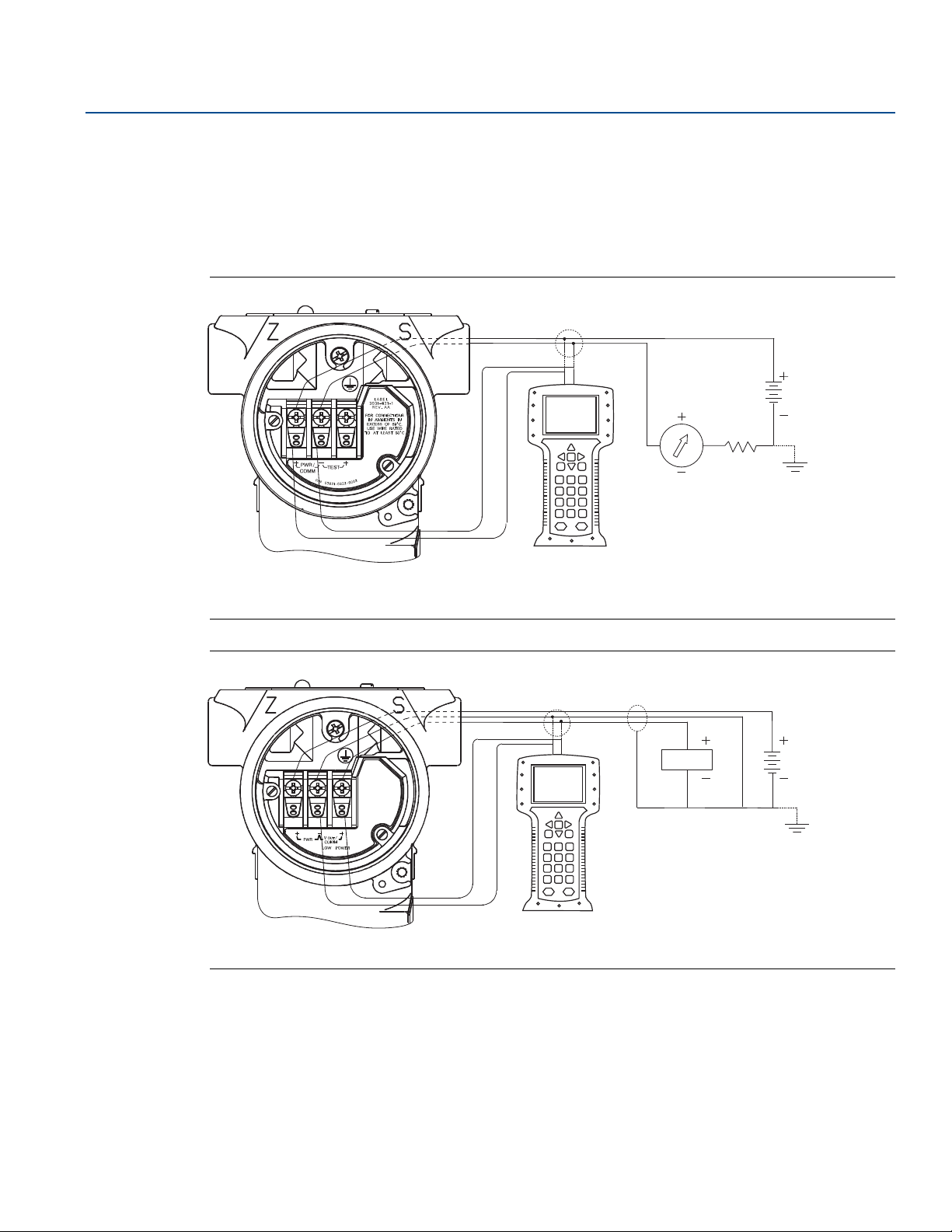
To commission on the bench, required equipment includes a power supply, a milliamp meter, and a Field
Communicator or AMS Device Manager. Wire equipment as shown in Figure 2-1 and Figure 2-2. To
ensure successful communication, a resistance of at least
250 ohms must be present between the Field Communicator loop connection and the power supply.
Connect the Field Communicator leads to the terminals labeled “COMM” on the terminal block.
Set all transmitter hardware adjustments during commissioning to avoid exposing the transmitter
electronics to the plant environment after installation.
When using a Field Communicator, any configuration changes made must be sent to the transmitter by
using the Send key. AMS Device Manager configuration changes are implemented when the Apply
button is clicked.
2.3.1 Setting the loop to manual
Whenever sending or requesting data that would disrupt the loop or change the output of the
transmitter, set the process application loop to manual. The Field Communicator or AMS Device
Manager will prompt you to set the loop to manual when necessary. Acknowledging this prompt does
not set the loop to manual. The prompt is only a reminder; set the loop to manual as a
separate operation.
™
3051 Pressure Transmitters can be commissioned either before or after installation.
2.3.2 Wiring diagrams
Connect the equipment as shown in Figure 2-1 for 4–20 mA HART® or Figure 2-2 for 1-5 Vdc HART Low
Power. To ensure successful communication, a resistance of at least 250 ohms must be present between
the Field Communicator loop connection and the power supply. The Field Communicator or AMS Device
Manager may be connected at “COMM” on the transmitter terminal block or across the load resistor.
4
Configuration
Page 15
Reference Manual
A
B
C
00809-0100-4001, Rev KA
Connecting across the “TEST” terminals will prevent successful communication for 4–20 mA HART
output.
Turn on the Field Communicator by pressing the ON/OFF key or log into AMS Device Manager. The Field
Communicator or AMS Device Manager will search for a HART-compatible device and indicate when the
connection is made. If the Field Communicator or AMS Device Manager fail to connect, it indicates that
no device was found. If this occurs, refer to Section 5: Troubleshooting.
Figure 2-1. Wiring (4–20 mA)
Configuration
May 2017
A. Current meter
B. R
≥250Ω
L
C. 24 Vds supply
Figure 2-2. Wiring (Low-Power)
A. Voltmeter
B. 6 - 14 Vdc supply
A
B
Config uration
5
Page 16

Configuration
May 2017
2.4 Configuration data review
Note
Information and procedures in this section that make use of Field Communicator Fast Key sequences and
AMS Device Manager assume that the transmitter and communication equipment are connected,
powered, and operating correctly.
The following is a list of factory default configurations. These can be reviewed by using the Field
Communicator or AMS Device Manager.
Field Communicator
Reference Manual
00809-0100-4001, Rev KA
Traditional 4–20 mA Fast Keys
Traditional 1–5 Vdc Fast Keys
Device Dashboard Fast Keys
Enter the Fast Key sequence to view the configuration data.
Tra nsmitter mod el Typ e
Ta g Range
Date Descriptor
Message Minimum and maximum sensor limits
Minimum span Units
4 and 20 mA points Output (linear or sq. root)
Damping Alarm setting (high, low)
Security setting (on, off) Local zero/span keys (enabled, disabled)
Integral display Sensor fill
Isolator material Flange (type, material)
O-ring material Drain/Vent
Remote seal (type, fill fluid, isolator material, number) Transmitter S/N
Address Sensor S/N
1, 5
1, 5
1, 7
AMS Device Manager
Right click on the device and select Configuration Properties from the menu. Select the tabs to review
the transmitter configuration data.
6
Configuration
Page 17
Reference Manual
00809-0100-4001, Rev KA
2.5 Field Communicator
(Version 1.8)
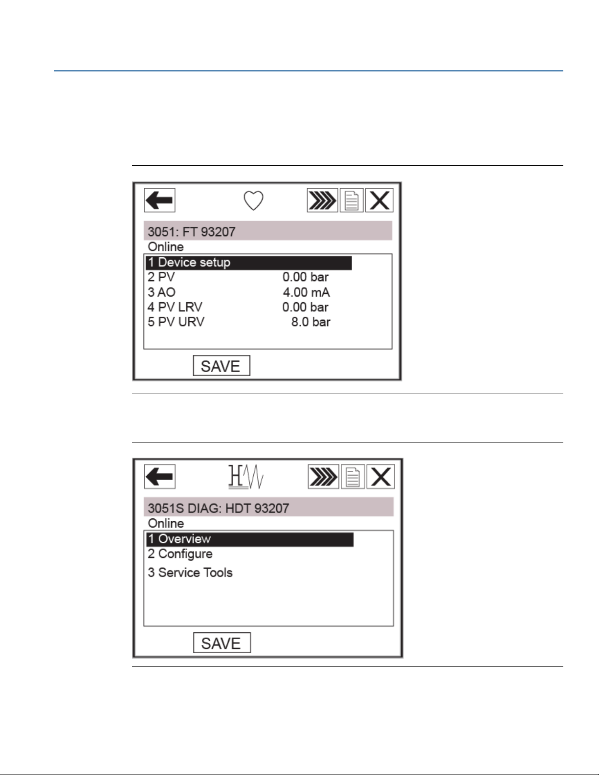
2.5.1 Field Communicator user interface
Figure 2-3. Traditional Interface
Configuration
May 2017
The corresponding menu trees can be viewed on page 8 and page 9.
The Fast Key sequence can be viewed on page 12.
Figure 2-4. Device Dashboard
The corresponding menu trees can be viewed on page 10 through page 12.
Config uration
The Fast Key sequence can be viewed on page 14.
7
Page 18
Configuration
May 2017
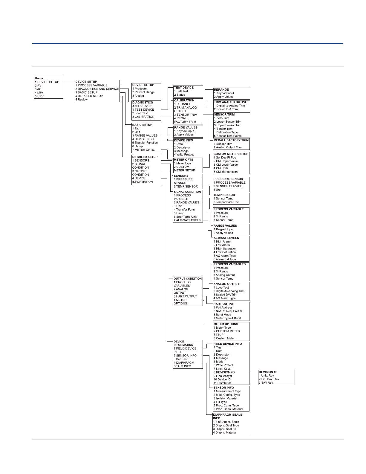
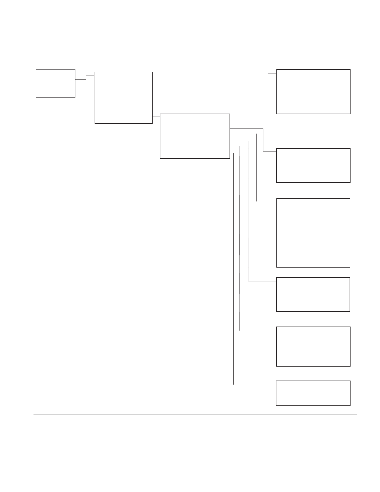
2.6 Field Communicator menu trees
Figure 2-5. Rosemount 3051 Traditional HART Menu Tree For 4-20 Ma HART Output
Reference Manual
00809-0100-4001, Rev KA
8
Configuration
Page 19
Reference Manual
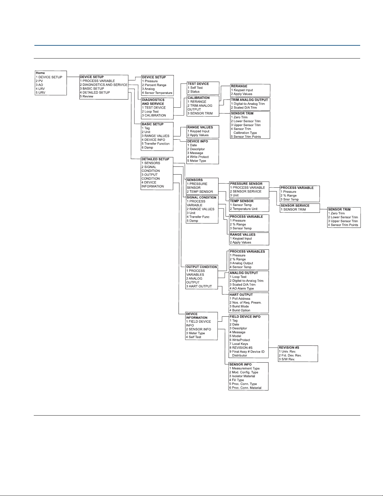
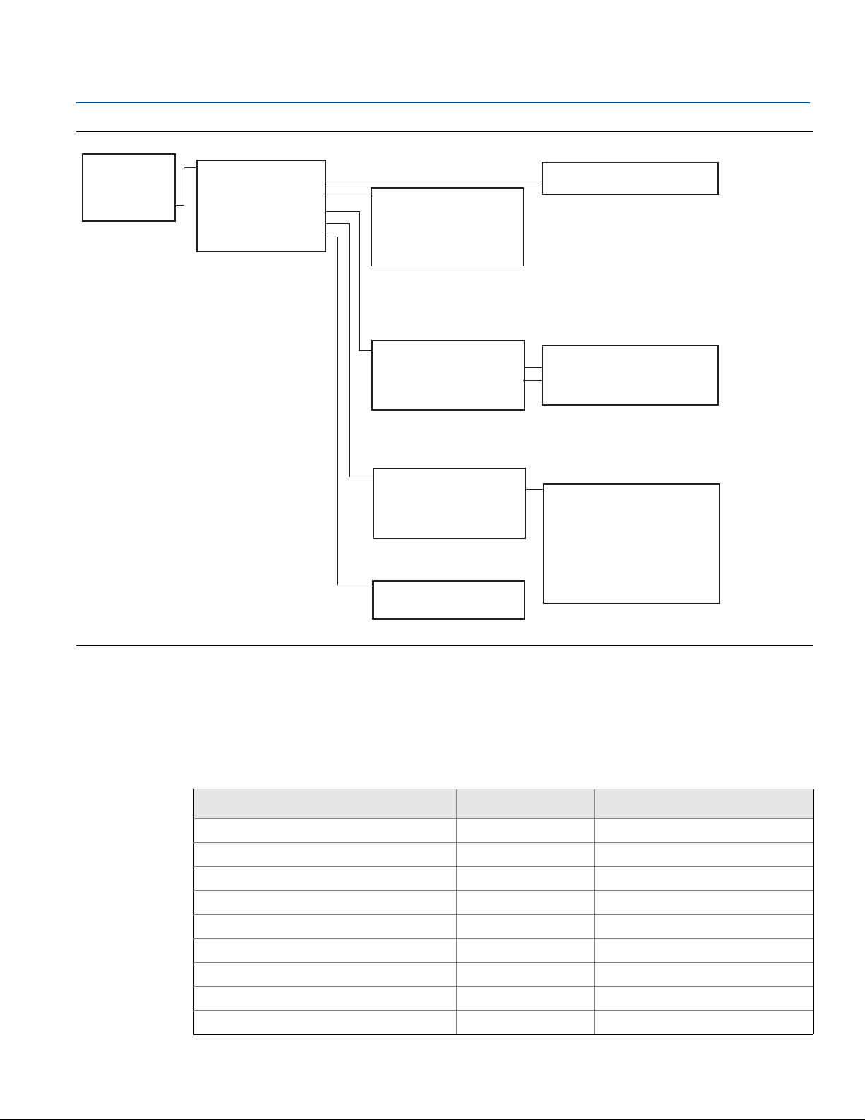
00809-0100-4001, Rev KA
Figure 2-6. Rosemount 3051 Traditional HART Menu Tree for 1-5 Vdc Low Power
Configuration
May 2017
Config uration
9
Page 20
Configuration
Home
1 Overview
2 Configure
3 Service Tools
Overview
1 Device Status
2 Comm Status
3 Pressure
4 Analog Output
5 Pressure URV
6 Pressure LRV
7 Device Information
Device Information
1 Identification
2 HART
3 Materials of Construction
4 RS Materials of Construction
5 Analog Alarm
6 Security
Identification
1 Tag
2 Model
3 Transmitter S/N
4 Date
5 Descriptor
6 Message
HART
1 Universal Revision
2 Field Device Revision
3 Hardware Revision
4 Software Revision
Materials of Construction
1 Sensor Config
2 Sensor Range
3 Upper Sensor Limits
4 Lower Sensor Limits
5 Isolator Material
6 Fill Fluid
7 Process Connection
8 Process Connection Matl
9 O-ring Material
Drain/Vent Material
RS Materials of Construction
1 Number of Remote Seals
2 RS Seal
3 RS Fill Fluid
4 RS Isolator Material
Analog Alarm
1 Alarm Direction
2 High Alarm
3 High Saturation
4 Low Saturation
5 Low Alarm
Security
1 Write Protect Status
2 Local Zero/Span
May 2017
Figure 2-7. Overview
Reference Manual
00809-0100-4001, Rev KA
10
Configuration
Page 21

Home
1 Overview
2 Configure
3 Service Tools
Configure
1 Guided Setup
2 Manual Setup
Guided Setup
1 Basic Setup
2 Zero
3 Configure Display
Manual Setup
1 Process Variables
2 Analog Output
3 Display
4 HART
5 Security
6 Device Information
Process Variables
1 Pressure Units
2 Damping
3 Transfer Function
4 Temperature Unit
5 Pressure
6 Sensor Temperature
Analog Output
1 Upper Range Value
2 Lower Range Value
3 Analog Output
4 Percent of Range
5 Upper Sensor Limits
6 Lower Sensor Limits
7 Minimum Span
8 Range by Applying Pressure
Display
1 Display Option
2 Decimal Places
3 Upper Range Value
4 Lower Range Value
5 Transfer Function
6 Units
HART
1 Burst Mode
2 Burst Option
3 Polling Address
Device Information
1 Identification
2 Flange
3 Remote Seal
Security
1 Write Protect Status
2 Local Zero/Span
Burst Option
PV
% range/current
Process Vars/current
Process Variables
Tag, Message, Descriptor, Date, Pressure Units,
Temperature Units, Damping, URV, LRV
Identification
1 Tag
2 Model
3 Transmitter S/N
4 Date
5 Descriptor
6 Message
Flange
1 Process Connection
2 Process Conn matl
3 O-ring Material
4 Drain/Vent Material
Remote Seal
1 Number of Remote Seals
2 RS Seal
3 RS Fill Fluid
4 RS Isolator Material
Reference Manual
00809-0100-4001, Rev KA
Figure 2-8. Configure
Configuration
May 2017
Config uration
11
Page 22
Configuration
Home
1 Overview
2 Configure
3 Service Tools
Service Tools
1 Alerts
2 Variables
3 Trends
4 Maintenance
5 Simulate
Variables
1 Variable Summary
2 Pressure
3 Analog Output
4 Sensor Temperature
Trends
1 Pressure
2 Sensor Temperature
Maintenance
1 Pressure Calibration
2 Analog Calibration
3 Recall Factory Calibration
Simulate
1 Loop Test
Alerts
1 Refresh Alerts
Only Active Alerts show up here
Trend Graph
Pressure Calibration
1 Upper
2 Lower
3 Zero
4 Upper Cal Pt
5 Lower Cal Pt
6 Upper Sensor Limits
7 Lower Sensor Limits
May 2017
Figure 2-9. Service Tools
Reference Manual
00809-0100-4001, Rev KA
2.7 Traditional Fast Key sequence
A check (⻫) indicates the basic configuration parameters. At minimum, these parameters should be
verified as part of the configuration and startup procedure.
Table 2-1. Traditional Fast Key Sequence
Function 4–20 mA HART 1–5 Vdc HART low power
12
⻫ Alarm and Saturation Levels 1, 4, 2, 7 N/A
Analog Output Alarm Type 1, 4, 3, 2, 4 1, 4, 3, 2, 4
Burst Mode Control 1, 4, 3, 3, 3 1, 4, 3, 3, 3
Burst Operation 1, 4, 3, 3, 4 1, 4, 3, 3, 4
Custom Meter Configuration 1, 3, 7, 2 N/A
Custom Meter Value 1, 4, 3, 4, 3 N/A
Damping 1, 3, 6 1, 3, 6
⻫
Date 1, 3, 4, 1 1, 3, 4, 1
Descriptor 1, 3, 4, 2 1, 3, 4, 2
Configuration
Page 23

Reference Manual
00809-0100-4001, Rev KA
Table 2-1. Traditional Fast Key Sequence
Function 4–20 mA HART 1–5 Vdc HART low power
Digital To Analog Trim (4-20 mA Output) 1, 2, 3, 2, 1 1, 2, 3, 2, 1
Disable Local Span/Zero Adjustment 1, 4, 4, 1, 7 1, 4, 4, 1, 7
Field Device Information 1, 4, 4, 1 1, 4, 4, 1
Full Trim 1, 2, 3, 3 1, 2, 3, 3
Keypad Input – Rerange 1, 2, 3, 1, 1 1, 2, 3, 1, 1
Local Zero and Span Control 1, 4, 4, 1, 7 1, 4, 4, 1, 7
Loop Test 1, 2, 2 1, 2, 2
Lower Sensor Trim 1, 2, 3, 3, 2 1, 2, 3, 3, 2
Message 1, 3, 4, 3 1, 3, 4, 3
Meter Options 1, 4, 3, 4 N/A
Number of Requested Preambles 1, 4, 3, 3, 2 1, 4, 3, 3, 2
Poll Address 1, 4, 3, 3, 1 1, 4, 3, 3, 1
Configuration
May 2017
Poll a Multidropped Transmitter Left Arrow, 4, 1, 1 Left Arrow, 4, 1, 1
Range Values 1, 3, 3 1, 3, 3
⻫
Rerange 1, 2, 3, 1 1, 2, 3, 1
Scaled D/A Trim (4–20 mA Output) 1, 2, 3, 2, 2 1, 2, 3, 2, 2
Self Test (Transmitter) 1, 2, 1, 1 1, 2, 1, 1
Sensor Info 1, 4, 4, 2 1, 4, 4, 2
Sensor Temperature 1, 1, 4 1, 1, 4
Sensor Trim Points 1, 2, 3, 3, 4 1, 2, 3, 3, 4
Status 1, 2, 1, 2 1, 2, 1, 2
⻫
Ta g 1, 3, 1 1, 3, 1
Transfer Function (Setting Output Type) 1, 3, 5 1, 3, 5
⻫
Transmitter Security (Write Protect) 1, 3, 4, 4 1, 3, 4, 4
Trim Analog Output 1, 2, 3, 2 1, 2, 3, 2
Units (Process Variable) 1, 3, 2 1, 3, 2
⻫
Upper Sensor Trim 1, 2, 3, 3, 3 1, 2, 3, 3, 3
Zero Trim 1, 2, 3, 3, 1 1, 2, 3, 3, 1
Config uration
13
Page 24

Configuration
May 2017
Reference Manual
00809-0100-4001, Rev KA
Table 2-2. Device Dashboard Fast Key Sequence
Function 4–20 mA HART
Alarm and saturation levels 1, 7, 5
Analog output alarm type 1, 7, 5
Burst mode control 2, 2, 4, 1
Burst option 2, 2, 4, 2
Custom display configuration 2, 2, 3
Damping 2, 2, 1, 2
Date 2, 2, 6, 1, 4
Descriptor 2, 2, 6, 1, 5
Digital to analog trim (4 - 20 mA output) 3, 4, 2
Disable zero and span adjustment 2, 2, 5, 2
Field device information 2, 2, 6
Loop test 3, 5, 1
Lower sensor trim 3, 4, 1, 2
Message 2, 2, 6, 1, 6
Poll address 2, 2, 4, 3
Range values 1, 5
Rerange with keypad 1, 5
Scaled D/A trim (4–20 mA output) 3, 4, 2
Sensor temperature/trend 3, 3, 2
Ta g 2, 2, 6, 1, 1
Tra nsfer func tio n 2, 2, 1, 3
Transmitter security (write protect) 2, 2, 5, 1
Units 2, 2, 1, 1
Upper sensor trim 3, 4, 1, 1
Zero trim 3, 4, 1, 3
2.8 Check output
Before performing other transmitter on-line operations, review the digital output parameters to ensure
that the transmitter is operating properly and is configured to the appropriate process variables.
14
Configuration
Page 25

Reference Manual
00809-0100-4001, Rev KA
2.8.1 Process variables
The process variables for the Rosemount 3051 provide transmitter output, and are continuously
updated. The pressure reading in both engineering units and percent of range will continue to track with
pressures outside of the defined range from the lower to the upper range limit of the sensor module.
Field Communicator
Configuration
May 2017
Traditional 4–20 mA Fast Keys
Traditional 1–5 Vdc Fast Keys
Device Dashboard Fast Keys
The process variable menu displays the following process variables:
Pressure
Percent of range
Analog output
AMS Device Manager
Right click on the device and select Process Variables... from the menu.The Process Variable screen
displays the following process variables:
Pressure
Percent of range
Analog output
2.8.2 Sensor temperature
The Rosemount 3051 contains a temperature sensor near the pressure sensor in the sensor module.
When reading this temperature, keep in mind the sensor is not a process temperature reading.
Field Communicator
1, 1
1, 1
3, 2
Traditional 4–20 mA Fast Keys
Traditional 1–5 Vdc Fast Keys
Device Dashboard Fast Keys
Enter the Fast Key sequence “Sensor Temperature” to view the sensor temperature reading.
AMS Device Manager
Right click on the device and select Process Variables... from the menu. Snsr Temp is the sensor
temperature reading.
2.9 Basic setup
2.9.1 Set process variable units
The PV Unit command sets the process variable units to allow you to monitor your process using the
appropriate units of measure.
Config uration
1, 1, 4
1, 1, 4
3, 2, 4
15
Page 26

Configuration
May 2017
Reference Manual
00809-0100-4001, Rev KA
Field Communicator
Traditional 4–20 mA Fast Keys
Traditional 1–5 Vdc Fast Keys
Device Dashboard Fast Keys
Enter the Fast Key sequence “Set Process Variable Units.” Select from the following engineering units:
inH
inHg mbar atm
ftH
mmH
mmHg Pa
psi kPa
O bar torr
2
O g/cm
2
O kg/cm
2
2
2
AMS Device Manager
Right click on the device and select Configure from the menu. In the Basic Setup tab, select Unit from the
drop down menu to select units.
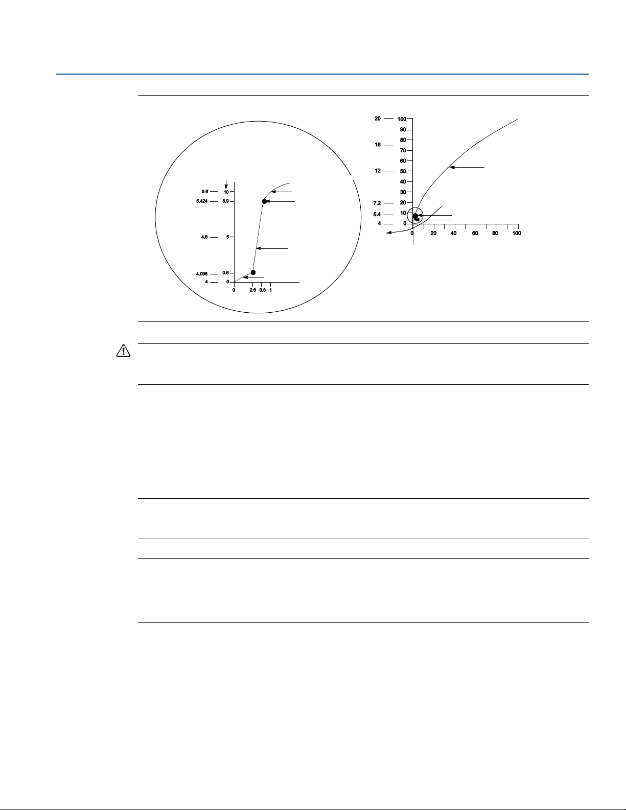
2.9.2 Set output (transfer function)
The Rosemount 3051 has two output settings: linear and square root. Activate the square root output
option to make analog output proportional to flow. As input approaches zero, the Rosemount 3051
automatically switches to linear output in order to ensure a more smooth, stable output near zero (see
Figure 2-10).
1, 3, 2
1, 3, 2
2, 2, 1, 1
inH2O at 4 °C
mmH2O at 4 °C
For 4–20 mA HART output, the slope of the curve is unity (y = x) from 0 to 0.6 percent of the ranged
pressure input. This allows accurate calibration near zero. Greater slopes would cause large changes in
output (for small changes at input). From 0.6 to 0.8 percent, curve slope equals 42 (y = 42x) to achieve
continuous transition from linear to square root at the transition point.
Field Communicator
Traditional 4–20 mA Fast Keys
Traditional 1–5 Vdc Fast Keys
Device Dashboard Fast Keys
1, 3, 5
1, 3, 5
2, 2, 1, 3
AMS Device Manager
1. Riht click on the device and select Configure from the menu.
2. In the Basic Setup tab, use Xfer fnctn drop down menu to select output, click Apply.
3. After carefully reading the warning provided, select yes.
16
Configuration
Page 27
Reference Manual
Sq. Root
Curve
Tra nsitio n Po int
Linear Section
Slope=1
Slope=42
Tra nsi tion Point
Sq. Root Curve
Full Scale
Flow (%)
Full Scale
Output
(mA dc)
00809-0100-4001, Rev KA
Figure 2-10. 4-20 mA HART Square Root Output Transition Point
Configuration
May 2017
Note
For a flow turndown of greater than 10:1 it is not recommended to perform a square root extraction in
the transmitter. Instead, perform the square root extraction in the system.
2.9.3 Rerange
The Range Values command sets each of the lower and upper range analog values (4 and 20 mA points
and 1 and 5 Vdc points) to a pressure. The lower range point represents 0 percent of range and the upper
range point represents 100 percent of range. In practice, the transmitter range values may be changed
as often as necessary to reflect changing process requirements. For a complete listing of range & sensor
limits, refer to “Range and sensor limits” on page 93.
Note
Transmitters are shipped from Emerson
(zero to upper range limit).
Note
Regardless of the range points, the Rosemount 3051 will measure and report all readings within the
digital limits of the sensor. For example, if the 4 and 20 mA points are set to 0 and 10 inH
transmitter detects a pressure of 25 inH
reading.
Select from one of the methods below to rerange the transmitter. Each method is unique; examine all
options closely before deciding which method works best for your process.
Rerange with a Field Communicator or AMS Device Manager only.
Rerange with a pressure input source and a Field Communicator or AMS Device Manager.
Rerange with a pressure input source and the local zero and span buttons (option D4).
™
fully calibrated per request or by the factory default of full scale
O, and the
O, it digitally outputs the 25 inH2O reading and a 250% of range
2
2
Config uration
17
Page 28

Configuration
May 2017
Reference Manual
00809-0100-4001, Rev KA
Note
If the transmitter security switch is ON, adjustments to the zero and span will not be able to be made.
Refer to “Configure security and alarm” on page 44 for security information.
Rerange with a Field Communicator or AMS Device Manager only.
The easiest and most popular way to rerange is to use the Field Communicator only. This method
changes the range values of the analog 4 and 20 mA points (1 and 5 Vdc points) independently without a
pressure input. This means that when you change either the 4 or 20 mA setting, you also change the
span.
An example for the 4–20 mA HART output:
If the transmitter is ranged so that
4 mA = 0 inH
20 mA = 100 inH
and you change the 4 mA setting to 50 inH
4 mA = 50 inH
20 mA = 100 inH
Note that the span was also changed from 100 inH
100 inH
O, and
2
O,
2
O using the communicator only, the new settings are:
2
O, and
2
O.
2
O to 50 inH2O, while the 20 mA setpoint remained at
2
O.
2
To obtain reverse output, simply set the 4 mA point at a greater numerical value than the 20 mA point.
Using the above example, setting the 4 mA point at 100 inH
0 inH
O will result in reverse output.
2
O and the 20 mA point at
2
Field Communicator
Traditional 4-20 mA Fast Keys
Traditional 1-5 Vdc Fast Keys
Device Dashboard Fast Keys
From the HOME screen, enter the Fast Key sequence “Rerange with a Communicator Only.”
1, 2, 3, 1
1, 2, 3, 1
2, 2, 2, 1
AMS Device Manager
Right click on the device and select Configure from the menu. In the Basic Setup tab, locate the Analog
Output box and perform the following procedure:
18
1. Enter the lower range value (LRV) and the upper range value (URV) in the fields provided. Select
Apply.
2. After carefully reading the warning provided, select yes.
Rerange with a pressure input source and a Field Communicator or
AMS Device Manager
Reranging using the Field Communicator and applied pressure is a way of reranging the transmitter
when specific 4 and 20 mA points (1 and 5 Vdc points) are not calculated.
Configuration
Page 29

Reference Manual
00809-0100-4001, Rev KA
Note
The span is maintained when the 4 mA point (1 Vdc point) is set. The span changes when the 20 mA
point (5 Vdc point) is set. If the lower range point is set to a value that causes the upper range point to
exceed the sensor limit, the upper range point is automatically set to the sensor limit, and the span is
adjusted accordingly.
Field Communicator
Configuration
May 2017
Traditional 4–20 mA Fast Keys
Traditional 1–5 Vdc Fast Keys
Device Dashboard Fast Keys
From the HOME screen, enter the Fast Key sequence Rerange with a pressure input source and a Field
Communicator or AMS Device Manager .
1, 2, 3, 1, 2
1, 2, 3, 1, 2
2, 2, 2, 8
AMS Device Manager
1. Right click on the device, select Calibrate, then Apply values from the menu.
2. Select Next after the control loop is set to manual.
3. From the Apply Values menu, follow the on-line instructions to configure lower and upper range
values.
4. Select Exit to leave the Apply Values screen.
5. Select Next to acknowledge the loop can be returned to automatic control.
6. Select Finish to acknowledge the method is complete.
Rerange with a pressure input source and the local zero and span
buttons (option D4)
Reranging using the local zero and span adjustments (see Figure 2-11 on page 20) and a pressure source
is a way of reranging the transmitter when specific 4 and 20 mA (1 and 5 Vdc) points are not known and a
communicator is not available.
Config uration
Note
When you set the 4 mA (1 Vdc) point the span is maintained; when you set the 20 mA (5 Vdc) point the
span changes. If you set the lower range point to a value that causes the upper range point to exceed the
sensor limit, the upper range point is automatically set to the sensor limit, and the span is adjusted
accordingly.
To rerange the transmitter using the span and zero buttons, perform the following procedure:
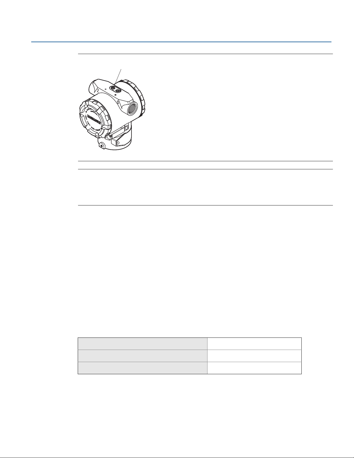
1. Loosen the screw holding the certifications label on the top of the transmitter housing. Slide the label
to expose the zero and span buttons. See Figure 2-11.
2. Apply the desired 4 mA (1 Vdc) pressure value to the transmitter. Push and hold the zero adjustment
button for at least two seconds but no longer than 10 seconds.
3. Apply the desired 20 mA (5 Vdc) pressure value to the transmitter. Push and hold the span
adjustment button for at least two seconds but no longer than 10 seconds.
19
Page 30
Configuration
A
May 2017
Reference Manual
00809-0100-4001, Rev KA
Figure 2-11. Zero and Span Button
A. Span and zero adjustment buttons
Note
The span is maintained when the 4 mA point (1 Vdc point) is set. The span changes when the 20 mA
point (5 Vdc point) is set. If the lower range point is set to a value that causes the upper range point to
exceed the sensor limit, the upper range point is automatically set to the sensor limit, and the span is
adjusted accordingly.
2.9.4 Damping
The “Damp” command introduces a delay in the micro-processing which increases the response time of
the transmitter; smoothing variations in output readings caused by rapid input changes. Determine the
appropriate damping setting based on the necessary response time, signal stability, and other
requirements of the loop dynamics within your system. The default damping value is 0.4 seconds and it
can be set to any of ten pre-configured damping values between 0 and 25.6 seconds. See list below.
0.00 second 0.05 second 0.10 second
0.20 second 0.40 second 0.80 second
1.60 seconds 3.20 seconds 6.40 seconds
12.8 seconds 25.6 seconds
The current damping value can be determined by executing the Field Communicator Fast Keys or going
to Configure in AMS Device Manager.
Field Communicator
Traditional 4–20 mA Fast Keys
Traditional 1–5 Vdc Fast Keys
Device Dashboard Fast Keys
AMS Device Manager
1, 3, 6
1, 3, 6
2, 2, 1, 2
20
1. Right click on the device and select Configure from the menu.
2. In the Basic Setup tab, enter the damping value in the Damp field, select Apply.
3. After carefully reading the warning provided, select yes.
Configuration
Page 31

Reference Manual
00809-0100-4001, Rev KA
2.10 LCD display
The LCD display connects directly to the interface board which maintains direct access to the signal
terminals. The display indicates output and abbreviated diagnostic messages. A display cover is provided
to accommodate the display.
For 4–20 mA HART output, the LCD display features a two-line display. The first line of five characters
displays the actual measured value, the second line of six characters displays the engineering units. The
LCD diplay can also show diagnostic messages. Refer to Figure 2-12.
For 1–5 Vdc HART Low Power output, the LCD display features a single-line display with four characters
that display the actual value. The LCD display can also show diagnostic messages. Refer to Figure 2-12.
Figure 2-12. LCD Display
4–20 mA HART 1–5 Vdc HART Low Power
Configuration
May 2017
2.10.1 LCD display configuration for 4–20 mA HART only
The factory default alternates are between Engineering Units and % of Range. The LCD Display
Configuration command allows customization of the LCD display to suit application requirements. The
LCD display will alternate between the selected items
Eng. Units only Alternate Eng. Units and % of Range
% of Range only Alternate Eng. Units and Custom Display
Custom Display only Alternate % of Range and Custom Display
Field Communicator
Traditional 4-20 mA Fast Keys
Device Dashboard Fast Keys
To change the standard default to one of the above options, follow these steps:
1. From the communicators main menu select 1: Device Setup, 3: Basic Setup,
7: Meter Options.
2. Select 1: Meter Type. Using the up or down arrows scroll up or down until the desired display has
been highlighted. Press ENTER, SEND, and HOME.
Config uration
1, 3, 7
2, 2, 3
21
Page 32

Configuration
See “Safety messages” on page 3 for complete warning information.
May 2017
00809-0100-4001, Rev KA
AMS Device Manager
1. Right click on the device and select Configuration Properties from the menu.
2. In the Local Display tab, locate the Meter Type area. Select the desired options to suit your application
needs, select Apply.
3. An Apply Parameter Modification screen appears, enter desired information and select OK.
4. After carefully reading the warning provided, select OK.
2.10.2 Custom display configuration 4–20 mA HART only
The user-configurable scale is a feature that enables the LCD display to show flow, level, or custom
pressure units. With this feature you can define the decimal point position, the upper range value, the
lower range value, the engineering units, and the transfer function.The display can be configured using a
Field Communicator or AMS Device Manager.
The user-configurable scale feature can define:
decimal point position
upper range values
lower range values
engineering units
transfer function
Reference Manual
To configure the display with a Field Communicator, perform the following procedure:
1. Change the Meter Type to “Custom Meter” by using the Fast Key sequence under “LCD display
configuration for 4–20 mA HART only” on page 21.
2. Next from the ONLINE screen, Select 1: Device Setup, 3: Basic Setup, 7: Meter Options, 2: Meter
Options, 2: Custom Meter Setup.
3. To specify decimal point position:
a. Select 1: Sel dec pt pos. Select the decimal point representation that will provide the most
accurate output for your application. For example, when outputting between zero and 75 GPM,
select XX.XXX or use the decimal point examples below:
XXXXX
XXXX.X
XXX.XX
XX.XXX
X.XXXX
Note
Make sure the selection has been sent and the decimal point has changed before proceeding to the next
step.
b. Select SEND.
4. To specify a custom upper range value:
a. Select 2: CM Upper Value. Type the value that you want the transmitter to read at the 20 mA
point.
b. Select SEND.
22
Configuration
Page 33

Reference Manual
00809-0100-4001, Rev KA
5. To specify a custom lower range value:
a. Select 3: CM Lower Value. Type the value that you want the transmitter to read at the 4 mA
point.
b. Select SEND.
6. To define custom units:
a. Select 4: CM Units. Enter the custom units (five characters maximum) to show on LCD display.
b. Select SEND.
7. To select the transmitter transfer function for the display:
a. Select 5: CM xfer fnct. Enter the transmitter transfer function for the display. Select sq root to
display flow units. The custom meter transfer function is independent of the analog output
transfer function.
8. Select SEND to upload the configuration to the transmitter.
2.11 Detailed setup
2.11.1 Failure mode alarm and saturation
Configuration
May 2017
The Rosemount 3051 Transmitters automatically and continuously perform self-diagnostic routines. If
the self-diagnostic routines detect a failure, the transmitter drives its output outside of the normal
saturation values. The transmitter will drive its output low or high based on the position of the failure
mode alarm jumper. See Ta bl e 2 - 3, Tab l e 2 -4 , and Ta b le 2- 5 for failure mode and saturation output
levels. To select alarm position, see “Configure security and alarm” on page 44.
Table 2-3. 4–20 mA HART Alarm and Saturation Values
Level 4–20 mA saturation 4–20 mA alarm
Low 3.9 mA ≤ 3.75 mA
High 20.8 mA ≥ 21.75 mA
Table 2-4. NAMUR-Compliant Alarm and Saturation Values
Level 4–20 mA saturation 4–20 mA alarm
Low 3.8 mA ≤ 3.6 mA
High 20.5 mA ≥ 22.5 mA
Table 2-5. 1–5 Vdc HART Low-Power Alarm and Saturation Values
Level 1–5 V saturation 1–5 V alarm
Config uration
Low 0.97 V ≤ 0.95 V
High 5.20 V ≥ 5.4 V
Alarm level values will be affected by analog trim. Refer to “Digital-to-Analog trim” on page 69.
23
Page 34

Configuration
May 2017
Note
When a transmitter is in an alarm condition, the Field Communicator indicates the analog output the
transmitter would drive if the alarm condition did not exist. The transmitter will alarm high in the event
of failure if the alarm jumper is removed.
2.11.2 Alarm and saturation levels for burst mode
Transmitters set to burst mode handle saturation and alarm conditions differently.
Alarm conditions
Analog output switches to alarm value.
Primary variable is burst with a status bit set.
Percent of range follows primary variable .
Temperature is burst with a status bit set.
Saturation
Analog output switches to saturation value.
Primary variable is burst normally.
Temperature is burst normally.
Reference Manual
00809-0100-4001, Rev KA
2.11.3 Alarm and saturation values for multidrop mode
Transmitters set to multidrop mode handle saturation and alarm conditions differently.
Alarm conditions
Primary variable is sent with a status bit set.
Percent of range follows primary variable .
Temperature is sent with a status bit set.
Saturation
Primary variable is sent normally.
Temperature is sent normally.
2.11.4 Alarm level verification
If the transmitter electronics board, sensor module, or LCD display is repaired or replaced, verify the
transmitter alarm level before returning the transmitter to service. This feature is also useful in testing
the reaction of the control system to a transmitter in an alarm state. To verify the transmitter alarm
values, perform a loop test and set the transmitter output to the alarm value (see Tables 2-3, 2-4, and 2-5
on page 23, and “Loop test” on page 24).
2.12 Diagnostics and service
Diagnostics and service functions listed below are primarily for use after field installation. The Loop Test
feature is designed to verify proper loop wiring and transmitter output.
2.12.1 Loop test
The loop test command verifies the output of the transmitter, the integrity of the loop, and the
operations of any recorders or similar devices installed in the loop.
24
Configuration
Page 35

Reference Manual
00809-0100-4001, Rev KA
Field Communicator
Configuration
May 2017
Traditional 4–20 mA Fast Keys
Traditional 1–5 Vdc Fast Keys
Device Dashboard Fast Keys
To initiate a loop test, perform the following procedure:
1. For 4–20 mA HART output, connect a reference meter to the transmitter by either connecting the
meter to the test terminals on the terminal block, or shunting transmitter power through the meter
at some point in the loop.
For 1–5 Vdc Low Power HART output, connect a reference meter to the V
2. From the HOME screen, enter the Fast Key sequence “Loop Test” to verify the output of the
transmitter.
3. Select OK after the control loop is set to manual (see “Setting the loop to manual” on page 4).
4. Select a discrete milliamp level for the transmitter to output. At the CHOOSE ANALOG OUTPUT prompt
select 1: 4mA (1 Vdc), select 2: 20mA (5 Vdc), or select 3: “Other” to manually input a value.
a. If you are performing a loop test to verif y the output of a transmitter, enter a value between 4 and
20 mA (1 and 5 Vdc).
b. If you are performing a loop test to verify alarm levels, enter the value representing an alarm state
(see Tables 2-3, 2-4, and 2-5 on page 23).
5. Check that the reference meter displays the commanded output value.
a. If the values match, the transmitter and the loop are configured and functioning properly.
b. If the values do not match, the meter may be attached to the wrong loop, there may be a fault in
the wiring or power supply, the transmitter may require an output trim, or the reference meter
may be malfunctioning.
1, 2, 2
1, 2, 2
3, 5, 1
terminal.
out
Config uration
After completing the test procedure, the display returns to the Loop Test screen to select another output
value or to end loop testing.
AMS Device Manager
1. Right click on the device and select Diagnostics and Test, then Loop Test from the menu.
2. For 4-20 mA HART output, connect a reference meter to the transmitter by either connecting the
meter to the test terminals on the terminal block, or shunting transmitter power through the meter
at some point in the loop.
For 1-5 Vdc Low Power HART output, connect a reference meter to the V
3. Select Next after setting the control loop to manual.
4. Select desired analog output level. Select Next.
5. Select Next to acknowledge output being set to desired level.
6. Check that the reference meter displays the commanded output value.
a. If the values match, the transmitter and the loop are configured and functioning properly.
b. If the values do not match, the meter may be attached to the wrong loop, there may be a fault in
the wiring or power supply, the transmitter may require an output trim, or the reference meter
may be malfunctioning.
terminal.
out
25
Page 36

Configuration
May 2017
After completing the test procedure, the display returns to the Loop Test screen to choose another
output value or to end loop testing.
7. Select End and click Next to end loop testing.
8. Select Next to acknowledge the loop can be returned to automatic control.
9. Select Finish to acknowledge the method is complete.
2.13 Advanced functions
2.13.1 Saving, recalling, and cloning configuration data
Use the cloning feature of the Field Communicator or the AMS Device Manager “User Configuration”
feature to configure several Rosemount 3051 Transmitters similarly. Cloning involves configuring a
transmitter, saving the configuration data, then sending a copy of the data to a separate transmitter.
Several possible procedures exist when saving, recalling, and cloning configuration data. For complete
instructions refer to the Field Communicator Reference Manual
One common method is as follows:
or AMS Device Manager online guides.
Reference Manual
00809-0100-4001, Rev KA
Field Communicator
Traditional 4–20 mA Fast Keys
Traditional 1–5 Vdc Fast Keys
Device Dashboard Fast Keys
1. Completely configure the first transmitter.
2. Save the configuration data:
a. Select SAVE from the Field Communicator HOME/ONLINE screen.
b. Ensure that the location to which the data will be saved is set to MODULE. If it is not, select
1: Location to set the save location to MODULE.
c. Select 2: Name, to name the configuration data. The default is the transmitter tag number.
d. Ensure that the data type is set to STANDARD. If the data type is NOT
Typ e to set the data type to STANDARD.
e. Select SAVE.
3. Connect and power the receiving transmitter and Field Communicator.
4. Select the back arrow from the HOME/ONLINE screen. The Field Communicator menu appears.
5. Select 1: Offline, 2: Saved Configuration, 1: Module Contents to reach the MODULE CONTENTS
menu.
6. Use the DOWN ARROW to scroll through the list of configurations in the memory module, and use
the RIGHT ARROW to select and retrieve the required configuration.
left arrow, 1, 2
left arrow, 1, 2
3, 4, 3
STANDARD, select 3: Data
26
7. Select 1: Edit.
8. Select 1: Mark All.
9. Select Save.
10.Use the DOWN ARROW to scroll through the list of configurations in the memory module, and use
the RIGHT ARROW to select the configuration again.
Configuration
Page 37

Reference Manual
00809-0100-4001, Rev KA
11.Select 3: Send to download the configuration to the transmitter.
12.Select OK after the control loop is set to manual.
13.After the configuration has been sent, select OK to acknowledge that the loop can be returned to
automatic control.
When finished, the Field Communicator informs you of the status. Repeat steps 3 through 13 to
configure another transmitter.
Note
The transmitter receiving cloned data must have the same software version (or later) as the original
transmitter.
AMS Device Manager creating a reusable copy
To create a reusable copy of a configuration perform the following procedure:
1. Completely configure the first transmitter.
2. Select View then User Configuration View from the menu bar (or click the toolbar button).
Configuration
May 2017
3. In the User Configuration window, right click and select New from the context menu.
4. In the New window, select a device from the list of templates shown, and select OK.
5. The template is copied into the User Configurations window, with the tag name highlighted; rename
it as appropriate and press Enter.
Note
A device icon can also be copied by dragging and dropping a device template or any other device icon
from AMS Device Manager Explorer or Device Connection View into the User Configurations window.
The Compare Configurations window appears, showing the current values of the copied device on one
side and mostly blank fields on the other (User Configuration) side.
6. Transfer values from the current configuration to the user configuration as appropriate or enter values
by typing the values into the available fields.
7. Select Apply to apply the values, or select OK to apply the values and close the window.
AMS Device Manager applying a user configuration
Any amount of user configurations can be created for the application. They can also be saved, and
applied to connected devices or to devices in the device list or plant database.
Note
When using AMS Device Manager Revision 6.0 or later, the device to which the user configuration is
applied, must be the same model type as the one created in the user configuration. When using AMS
Device Manager Revision 5.0 or earlier, the same model type and revision number are required.
Config uration
27
Page 38

Configuration
May 2017
To apply a user configuration perform the following procedure:
1. Select the desired user configuration in the User Configurations window.
2. Drag the icon onto a like device in AMS Device Manager Explorer or Device Connection View. The
Compare Configurations window opens, showing the parameters of the target device on one side and
the parameters of the user configuration on the other.
3. Transfer parameters from the user configuration to the target device as desired. Click OK to apply the
configuration and close the window.
2.13.2 Burst mode
When configured for burst mode, the Rosemount 3051 provides faster digital communication from the
transmitter to the control system by eliminating the time required for the control system to request
information from the transmitter. Burst mode is compatible with the analog signal. Because the HART
protocol features simultaneous digital and analog data transmission, the analog value can drive other
equipment in the loop while the control system is receiving the digital information. Burst mode applies
only to the transmission of dynamic data (pressure and temperature in engineering units, pressure in
percent of range, and/or analog output), and does not affect the way other transmitter data is accessed.
Access to information other than dynamic transmitter data is obtained through the normal
poll/response method of HART Communication. A Field Communicator, AMS Device Manager or the
control system may request any of the information that is normally available while the transmitter is in
burst mode. Between each message sent by the transmitter, a short pause allows the Field
Communicator, AMS Device Manager or a control system to initiate a request. The transmitter will
receive the request, process the response message, and then continue “bursting” the data
approximately three times per second.
Reference Manual
00809-0100-4001, Rev KA
Field Communicator
Traditional 4–20 mA Fast Keys
Traditional 1–5 Vdc Fast Keys
Device Dashboard Fast Keys
1, 4, 3, 3, 3
1, 4, 3, 3, 3
2, 2, 4, 1
AMS Device Manager
Right click on the device and select Configure from the menu.
1. In the HART tab, use the drop down menu to select “Burst Mode ON or OFF.” For “Burst option” select
the desired properties from the drop down menu. Burst options are as follows:
– PV
– % range/current
– Process vars/crnt
– Process variables
2. After selecting options click Apply.
3. After carefully reading the warning provided, select yes.
28
Configuration
Page 39

Reference Manual
00809-0100-4001, Rev KA
2.14 Multidrop communication
Multidropping transmitters refers to the connection of several transmitters to a single communications
transmission line. Communication between the host and the transmitters takes place digitally with the
analog output of the transmitters deactivated. With smart communications protocol, up to fifteen
transmitters can be connected on a single twisted pair of wires, or over leased phone lines.
Multidrop installation requires consideration of the update rate necessary from each transmitter, the
combination of transmitter models, and the length of the transmission line. Communication with
transmitters can be accomplished with HART modems and a host implementing HART protocol. Each
transmitter is identified by a unique address (1–15) and responds to the commands defined in the HART
protocol. Field Communicators and AMS Device Manager can test, configure, and format a multidropped
transmitter the same way as a transmitter in a standard point-to-point installation.
Figure 2-13 shows a typical multidrop network. This figure is not intended as an installation diagram.
Note
A transmitter in multidrop mode has the analog output fixed at 4 mA. If an LCD display is installed to a
transmitter in multidrop mode, it will alternate the display between “current fixed” and the specified LCD
display output(s).
Configuration
May 2017
Figure 2-13. Typical Multidrop Network
A
B
The Rosemount 3051 is set to address zero (0) at the factory, which allows operation in the standard
point-to-point manner with a 4–20 mA output signal. To activate multidrop communication, the
transmitter address must be changed to a number from one to 15. This change deactivates the 4–20 mA
analog output, sending it to 4 mA. It also disables the failure mode alarm signal, which is controlled by
the upscale/downscale switch position. Failure signals in multidropped transmitters are communicated
through HART messages.
Config uration
29
Page 40

Configuration
May 2017
2.15 Changing a transmitter address
To activate multidrop communication, the transmitter poll address must be assigned a number from
one to 15, and each transmitter in a multidropped loop must have a unique poll address.
Field Communicator
Reference Manual
00809-0100-4001, Rev KA
Traditional 4–20 mA Fast Keys
Traditional 1–5 Vdc Fast Keys
Device Dashboard Fast Keys
1, 4, 3, 3, 1
1, 4, 3, 3, 1
1, 2
AMS Device Manager
Right click on the device and select Configuration Properties from the menu.
1. In the HART tab, in the ID box, enter poll address located in the Poll addr box, select Apply.
2. After carefully reading the warning provided, select yes.
2.15.1 Communicating with a multidropped transmitter
Field Communicator
Traditional 4–20 mA Fast Keys
Traditional 1–5 Vdc Fast Keys
Device Dashboard Fast Keys
To communicate with a multidropped transmitter, configure the Field Communicator to poll for a
non-zero address.
1. From the HOME screen, enter the Fast Key sequence “Communicating with a Multidropped
Tra n sm it ter .”
1, 4, 3, 3, 2
1, 4, 3, 3, 2
1, 2
2. On the polling menu, scroll down and select Digital Poll. In this mode, the Field Communicator
automatically polls for devices at addresses 0–15 upon start up.
AMS Device Manager
Click on the HART modem icon and select Scan All Devices.
2.15.2 Polling a multidropped transmitter
Polling a multidropped loop determines the model, address, and number of transmitters on the given
loop.
Field Communicator
Traditional 4–20 mA Fast Keys
Traditional 1–5 Vdc Fast Keys
Device Dashboard Fast Keys
AMS device manager
Click on the HART modem icon and select Scan All Devices.
30
Left arrow, 4, 1
Left arrow, 4, 1
1, 2
Configuration
Page 41

Reference Manual
00809-0100-4001, Rev KA
Section 3 Installation
Overview . . . . . . . . . . . . . . . . . . . . . . . . . . . . . . . . . . . . . . . . . . . . . . . . . . . . . . . . . . . . . . . . . . . . . . . . . . . . page 31
Safety messages . . . . . . . . . . . . . . . . . . . . . . . . . . . . . . . . . . . . . . . . . . . . . . . . . . . . . . . . . . . . . . . . . . . . . . page 31
General considerations . . . . . . . . . . . . . . . . . . . . . . . . . . . . . . . . . . . . . . . . . . . . . . . . . . . . . . . . . . . . . . . . page 32
Mechanical considerations . . . . . . . . . . . . . . . . . . . . . . . . . . . . . . . . . . . . . . . . . . . . . . . . . . . . . . . . . . . . . page 32
Draft range considerations . . . . . . . . . . . . . . . . . . . . . . . . . . . . . . . . . . . . . . . . . . . . . . . . . . . . . . . . . . . . . page 33
Environmental considerations . . . . . . . . . . . . . . . . . . . . . . . . . . . . . . . . . . . . . . . . . . . . . . . . . . . . . . . . . . page 33
HART installation flowchart . . . . . . . . . . . . . . . . . . . . . . . . . . . . . . . . . . . . . . . . . . . . . . . . . . . . . . . . . . . . page 34
Installation procedures . . . . . . . . . . . . . . . . . . . . . . . . . . . . . . . . . . . . . . . . . . . . . . . . . . . . . . . . . . . . . . . . page 35
Electrical considerations . . . . . . . . . . . . . . . . . . . . . . . . . . . . . . . . . . . . . . . . . . . . . . . . . . . . . . . . . . . . . . . page 46
Hazardous locations certifications . . . . . . . . . . . . . . . . . . . . . . . . . . . . . . . . . . . . . . . . . . . . . . . . . . . . . .page 51
Rosemount 305, 306, and 304 Manifolds . . . . . . . . . . . . . . . . . . . . . . . . . . . . . . . . . . . . . . . . . . . . . . . . page 51
Valve Components . . . . . . . . . . . . . . . . . . . . . . . . . . . . . . . . . . . . . . . . . . . . . . . . . . . . . . . . . . . . . . . . . . . . page 58
Installation
May 2017
3.1 Overview
The information in this section covers installation considerations for the Rosemount™ 3051 Pressure
Transmitter with HART
transmitter to describe basic pipe-fitting and wiring procedures for initial installation. Dimensional
drawings for each transmitter variation and mounting configuration are included on page 38.
®
protocols. A Quick Start Guide for HART protocol is shipped with every
3.2 Safety messages
Procedures and instructions in this section may require special precautions to ensure the safety of the
personnel performing the operation. Information that raises potential safety issues is indicated by a
warning symbol ( ). Refer to the following safety messages before performing an operation preceded
by this symbol.
Explosions could result in death or serious injury.
Installation of this transmitter in an explosive environment must be in accordance with the appropriate
local, national, and international standards, codes, and practices. Review the approvals section of this
manual for any restrictions associated with a safe installation.
Before connecting a Field Communicator in an explosive atmosphere, ensure the instruments in the
loop are installed in accordance with intrinsically safe or non-incendive field wiring practices.
In an Explosion-Proof/Flameproof installation, do not remove the transmitter covers when power is
applied to the unit.
Process leaks may cause harm or result in death.
Install and tighten process connectors before applying pressure.
Installation
31
Page 42

Installation
May 2017
Electrical shock can result in death or serious injury.
Avoid contact with the leads and terminals. High voltage that may be present on leads can cause
electrical shock.
Replacement equipment or spare parts not approved by Emerson
the pressure retaining capabilities of the transmitter and may render the instrument dangerous.
Use only bolts supplied or sold by Emerson as spare parts.
Refer to “Spare parts” on page 136 for a complete list of spare parts.
Improper assembly of manifolds to traditional flange can damage sensor module.
For safe assembly of manifold to traditional flange, bolts must break back plane of flange web (i.e.,
bolt hole) but must not contact sensor module housing.
3.3 General considerations
Measurement accuracy depends upon proper installation of the transmitter and impulse piping. Mount
the transmitter close to the process and use a minimum of piping to achieve best accuracy. Keep in mind
the need for easy access, personnel safety, practical field calibration, and a suitable transmitter
environment. Install the transmitter to minimize vibration, shock, and temperature fluctuation.
Reference Manual
00809-0100-4001, Rev KA
™
for use as spare parts could reduce
Important
Install the enclosed pipe plug (found in the box) in unused conduit opening with a minimum of five
threads engaged to comply with explosion-proof requirements.
Refer to Material Selection Consideration for Pressure Transmitters Technical Note
compatibility considerations.
3.4 Mechanical considerations
Note
For steam service or for applications with process temperatures greater than the limits of the
transmitter, do not blow down impulse piping through the transmitter. Flush lines with the blocking
valves closed and refill lines with water before resuming measurement.
Note
When the transmitter is mounted on its side, position the coplanar flange to ensure proper venting or
draining. Mount the flange as shown in Figure 3-8 on page 41, keeping drain/vent connections on the
bottom for gas service and on the top for liquid service.
for material
32
Installation
Page 43

Reference Manual
00809-0100-4001, Rev KA
3.5 Draft range considerations
Installation
For the Rosemount 3051CD0 Draft Range Pressure Transmitter, it is best to mount the transmitter with
the isolators parallel to the ground. Installing the transmitter in this way reduces oil head effect and
provides for optimal temperature performance.
Be sure the transmitter is securely mounted. Tilting of the transmitter may cause a zero shift in the
transmitter output.
Reducing process noise
There are two recommended methods of reducing process noise: output damping and, in gage
applications, reference side filtering.
Output damping
The output damping for the Rosemount 3051CD0 is factory set to 3.2 seconds as a default. If the
transmitter output is still noisy, increase the damping time. If faster response is needed, decrease the
damping time. Damping adjustment information is available on page 20.
Installation
May 2017
Reference side filtering
In gage applications it is important to minimize fluctuations in atmospheric pressure to which the low
side isolator is exposed.
One method of reducing fluctuations in atmospheric pressure is to attach a length of tubing to the
reference side of the transmitter to act as a pressure buffer.
Another method is to plumb the reference side to a chamber that has a small vent to atmosphere. If
multiple draft transmitters are being used in an application, the reference side of each device can be
plumbed to a chamber to achieve a common gage reference.
3.6 Environmental considerations
Best practice is to mount the transmitter in an environment that has minimal ambient temperature
change. The transmitter electronics temperature operating limits are –40 to 185 °F (–40 to 85 °C). Refer
to Figure 2-12 on page 21 that lists the sensing element operating limits. Mount the transmitter so that it
is not susceptible to vibration and mechanical shock and does not have external contact with corrosive
materials.
Installation
33
Page 44

START HERE
Bench
Calibration?
Field Install
No
Set Units
(page 15)
Set Range Points
(page 17)
Set Output Type
(page 16)
Set Damping
(page 20)
Ver ify
Apply Pressure
Yes
Within
Specifications?
Yes
No
Refer to
Section 4: Operation
and Maintenance
Configure Security
and Alarm
(page 44)
Mount Transmitter
(page 35)
Wire Transmitter
(pages 47–53)
Power Transmitter
(page 48)
Check Process
Connection
(page 41)
Tri m Tra nsmitt er for
Mounting Effects
(page 6)
Done
Review Transmitter
Configuration
(page 6)
Confirm Transmitter
Configuration
(page 6)
Configure
Installation
May 2017
3.7 HART installation flowchart
Figure 3-1. HART Flowchart
Reference Manual
00809-0100-4001, Rev KA
34
Installation
Page 45

Reference Manual
00809-0100-4001, Rev KA
3.8 Installation procedures
3.8.1 Mount the transmitter
For dimensional drawing information refer to Appendix A: Specifications and Reference Data on page 89.
Process flange orientation
Mount the process flanges with sufficient clearance for process connections. For safety reasons, place
the drain/vent valves so the process fluid is directed away from possible human contact when the vents
are used. In addition, consider the need for a testing or calibration input.
Note
Most transmitters are calibrated in the horizontal position. Mounting the transmitter in any other
position will shift the zero point to the equivalent amount of liquid head pressure caused by the varied
mounting position. To reset zero point, refer to “Sensor trim” on page 71.
Housing rotation
See “Housing rotation” on page 43.
Installation
May 2017
Terminal side of electronics housing
Mount the transmitter so the terminal side is accessible. Clearance of 0.75-in. (19 mm) is required for
cover removal. Use a conduit plug in the unused conduit opening.
Circuit side of electronics housing
Provide 0.75-in. (19 mm) of clearance for units with out an LCD display. Three inches of clearance is
required for cover removal if a meter is installed.
Cover installation
Always ensure a proper seal by installing the electronics housing cover(s) so that metal contacts metal.
Use Rosemount O-rings.
Environmental seal for housing
Thread sealing (PTFE) tape or paste on male threads of conduit is required to provide a water/dust tight
conduit seal and meets requirements of NEMA
Protection ratings are required.
For M20 threads, install conduit plugs to full thread engagement or until mechanical resistance is met.
®
Type 4X, IP66, and IP68. Consult factory if other Ingress
Mounting brackets
Rosemount 3051Transmitters may be panel-mounted or pipe-mounted through an optional mounting
bracket. Refer to Ta b l e 3- 1 for the complete offering and see Figure 3-2 through Figure 3-5 on pages 36
and 37 for dimensions and mounting configurations.
Installation
35
Page 46

Installation
B
2.8 (71)
A
3.4 (85)
May 2017
Reference Manual
00809-0100-4001, Rev KA
Table 3-1. Rosemount 3051 Mounting Brackets
Process connections Mounting Materials
Option
code
B4 X X N/A X X X N/A X N/A X
B1 N/A N/A X X N/A N/A X N/A X N/A
B2 N/A N/A X N/A X N/A X N/A X N/A
B3 N/A N/A X N/A N/A X X N/A X N/A
B7 N/A N/A X X N/A N/A X N/A N/A X
B8 N/A N/A X N/A X N/A X N/A N/A X
B9 N/A N/A X N/A N/A X X N/A N/A X
BA N/A N/A X X N/A N/A N/A X N/A X
BC N/A N/A X N/A N/A X N/A X N/A X
Coplanar In-line Traditional
Pipe
mount
Panel
mount
Flat
panel
mount
CS
bracket
SST
bracket
CS
bolts
SST
bolts
Figure 3-2. Mounting Bracket Option Code B4
A. 5/16 ⫻ 11/2 bolts for panel mounting (not supplied)
3
B.
/8–16 ⫻ 11/4 bolts for mounting to transmitter
Dimensions are in inches (millimeters)
Figure 3-3. Mounting Bracket Option Codes B1, B7, and BA
3.75 (95)
1.63 (41)
4.09 (104)
2.73 (69)
2.81
(71)
Dimensions are in inches (millimeters).
4.97 (126)
36
Installation
Page 47

Reference Manual
3.75 (95)
1.63 (41)
4.09
(104)
2.81
(71)
4.5
(114)
2.125
(54)
2.81
(71)
8.00
(203)
1.625
(41)
00809-0100-4001, Rev KA
Figure 3-4. Panel Mounting Bracket Option Codes B2 and B8
A. Mounting holes 0.375 diameter (10)
Dimensions are in inches (millimeters).
Figure 3-5. Flat Mounting Bracket Option Codes B3 and BC
1.40
(36)
Installation
May 2017
A
1.405
(35,7)
1.405
(35,7)
Dimensions are in inches (millimeters).
Flange bolts
B7M
316 B8M
KM
1. The last digit in the F593_ head marking may be any letter between A and M.
660
CL A
F593_
The Rosemount 3051 can be shipped with a coplanar flange or a traditional flange installed with four
1.75-in. flange bolts. Mounting bolts and bolting configurations for the coplanar and traditional flanges
can be found on page 39. Stainless steel bolts supplied by Emerson Process Management are coated with
a lubricant to ease installation. Carbon steel bolts do not require lubrication. No additional lubricant
should be applied when installing either type of bolt. Bolts supplied by Emerson are identified by their
head markings:
Carbon Steel (CS) head markings
Stainless Steel (SST) head markings
(1)
Alloy K-500 head marking
Installation
37
Page 48

Installation
See “Safety messages” on page 31 for complete warning information.
A
A
B
A
1.50 (38) × 4
1.50 (38) × 4
1.75 (44) × 4
1.75 (44) × 4
May 2017
Reference Manual
00809-0100-4001, Rev KA
Bolt installation
Only use bolts supplied with the Rosemount 3051 or sold by Emerson as spare parts for the transmitter.
Use the following bolt installation procedure:
1. Finger-tighten the bolts.
2. Torque the bolts to the initial torque value using a crossing pattern (see Ta b le 3 - 2 for torque values).
3. Torque the bolts to the final torque value using the same crossing pattern.
Table 3-2. Bolt Installation Torque Values
Bolt material Initial torque value Final torque value
CS-ASTM-A445 Standard 300 in-lb (34 N-m) 650 in-lb (73 N-m)
316 SST—Option L4 150 in-lb (17 N-m) 300 in-lb (34 N-m)
ASTM-A-19 B7M—Option L5 300 in-lb (34 N-m) 650 in-lb (73 N-m)
Alloy 400—Option L6 300 in-lb (34 N-m) 650 in-lb (73 N-m)
Figure 3-6. Traditional Flange Bolt Configurations
Differential transmitter Gage/absolute transmitter
A. Drain/vent
B. Plug
Dimensions are in inches (millimeters).
38
Installation
Page 49

Reference Manual
00809-0100-4001, Rev KA
Figure 3-7. Mounting Bolts and Bolt Configurations for Coplanar Flange
Installation
May 2017
Transmitter with flange bolts
Dimensions are in inches (millimeters).
Transmitter with flange adapters and
flange/adapter bolts
Description Qty Size in. (mm)
Differential pressure
Flange bolts 4 1.75 (44)
Flange/adapter bolts 4 2.88 (73)
Gage/absolute pressure
Flange bolts 4 1.75 (44)
Flange/adapter bolts 2 2.88 (73)
1. Rosemount 3051T transmitters are direct mount and do not require bolts for process connection.
3.8.2 Impulse piping
The piping between the process and the transmitter must accurately transfer the pressure to obtain
accurate measurements. There are five possible sources of error: pressure transfer, leaks, friction loss
(particularly if purging is used), trapped gas in a liquid line, liquid in a gas line, and density variations
between the legs.
The best location for the transmitter in relation to the process pipe is dependent on the process. Use the
following guidelines to determine transmitter location and placement of impulse piping:
Keep impulse piping as short as possible.
For liquid service, slope the impulse piping at least 1 in./ft (8 cm/m) upward from the transmitter
toward the process connection.
For gas service, slope the impulse piping at least 1 in./ft (8 cm/m) downward from the transmitter
toward the process connection.
(1)
Installation
39
Page 50

Installation
May 2017
Reference Manual
00809-0100-4001, Rev KA
Avoid high points in liquid lines and low points in gas lines.
Make sure both impulse legs are the same temperature.
Use impulse piping large enough to avoid friction effects and blockage.
Vent all gas from liquid piping legs.
When using a sealing fluid, fill both piping legs to the same level.
When purging, make the purge connection close to the process taps and purge through equal lengths
of the same size pipe. Avoid purging through the transmitter.
Keep corrosive or hot (above 250 °F [121 °C]) process material out of direct contact with the sensor
module and flanges.
Prevent sediment deposits in the impulse piping.
Maintain equal leg of head pressure on both legs of the impulse piping.
Avoid conditions that might allow process fluid to freeze within the process flange.
Mounting requirements
Impulse piping configurations depend on specific measurement conditions. Refer to Figure 3-8 for
examples of the following mounting configurations:
Liquid flow measurement
Place taps to the side of the line to prevent sediment deposits on the transmitter’s process isolators.
Mount the transmitter beside or below the taps so gases can vent into the process line.
Mount drain/vent valve upward to allow gases to vent.
Gas flow measurement
Place taps in the top or side of the line.
Mount the transmitter beside or above the taps so liquid will drain into the process line.
Steam flow measurement
Place taps to the side of the line.
Mount the transmitter below the taps to ensure that the impulse piping will stay filled with
condensate.
In steam service above 250 °F (121 °C), fill impulse lines with water to prevent steam from contacting
the transmitter directly and to ensure accurate measurement start-up.
Note
For steam or other elevated temperature services, it is important that temperatures at the process
connection do not exceed the transmitter’s process temperature limits.
40
Installation
Page 51

Reference Manual
Flow
Flow
Flow
00809-0100-4001, Rev KA
Figure 3-8. Installation Examples
Gas or liquid Gas Steam
Installation
May 2017
3.8.3 Process connections
Coplanar or traditional process connection
Install and tighten all four flange bolts before applying pressure, or process leakage will result. When
properly installed, the flange bolts will protrude through the top of the sensor module housing. Do not
attempt to loosen or remove the flange bolts while the transmitter is in service.
Flange adapters
Rosemount 3051DP and GP process connections on the transmitter flanges are 1/4–18 NPT. Flange
adapters are available with standard
disconnect from the process by removing the flange adapter bolts. Use plant-approved lubricant or
sealant when making the process connections. Refer to “Dimensional drawings” on page 101 for the
distance between pressure connections. This distance may be varied ±
both of the flange adapters.
To install adapters to a coplanar flange, perform the following procedure:
1. Remove the flange bolts.
2. Leaving the flange in place, move the adapters into position with the O-ring installed.
3. Clamp the adapters and the coplanar flange to the transmitter sensor module using the larger of the
bolts supplied.
4. Tighten the bolts. Refer to “Flange bolts” on page 37 for torque specifications.
Whenever you remove flanges or adapters, visually inspect the PTFE O-rings. Replace with O-ring
designed for Rosemount transmitter if there are any signs of damage, such as nicks or cuts. Undamaged
O-rings may be reused. If you replace the O-rings, retorque the flange bolts after installation to
compensate for cold flow. Refer to the process sensor body reassembly procedure in Section 5: Trouble-
shooting.
1
/2–14 NPT Class 2 connections. The flange adapters allow users to
1
/8-in. (3.2 mm) by rotating one or
Installation
41
Page 52

Installation
A
A
B
B
C
C
D
D
ROSEMOUNT 1151
ROSEMOUNT 3051S/3051/2051/3001/3095/2024
May 2017
Reference Manual
00809-0100-4001, Rev KA
O-rings
The two styles of Rosemount flange adapters (Rosemount 1151 and Rosemount
3051S/3051/2051/3095) each require a unique O-ring. Use only the O-ring designed for the
corresponding flange adaptor.
Failure to install proper flange adapter O-rings may cause process leaks, which can result in death or serious injury.
The two flange adapters are distinguished by unique O-ring grooves. Only use the O-ring that is designed for its
specific flange adapter, as shown below.
A. Flange Adapter
B. O-ring
C. PTFE
D. Elastomer
When compressed, PTFE O-rings tend to “cold flow,” which aids in their sealing capabilities.
Note
PTFE O-rings should be replaced if the flange adapter is removed.
3.8.4 Inline process connection
Inline gage transmitter orientation
The low side pressure port on the inline gage transmitter is located in the neck of the transmitter, behind
the housing. The vent path is 360 degrees around the transmitter between the housing and sensor (See
Figure 3-9).
Keep the vent path free of any obstruction, such as paint, dust, and lubrication by mounting the
transmitter so that the process can drain away.
42
Installation
Page 53

Reference Manual
A
B
A
00809-0100-4001, Rev KA
Figure 3-9. In-Line Gage Low Side Pressure Port
A. Low side pressure port (atmospheric reference)
Do not apply torque directly to the sensor module. Rotation between the sensor module and the
process connection can damage the electronics. To avoid damage, apply torque only to the hex-shaped
process connection.
Installation
May 2017
A
A. Sensor module
B. Process connection
3.8.5 Housing rotation
The electronics housing can be rotated up to 180 degrees in either direction to improve field access, or
to better view the optional LCD display. To rotate the housing, perform the following procedure:
1. Loosen the housing rotation set screw using a
2. Turn the housing left or right up to 180° from its original position. Over rotating will damage the
transmitter.
3. Retighten the housing rotation set screw.
Figure 3-10. Housing Rotation
5
/64-in. hex wrench.
A. Housing rotation set screw (5/64-in.)
Installation
43
Page 54

Installation
A
B
C
D
May 2017
3.8.6 LCD display
Transmitters ordered with the LCD option are shipped with the display installed. Installing the display on
an existing Rosemount 3051 Transmitter requires a small instrument screwdriver.
Figure 3-11. LCD Display
A. Extended cover
B. LCD display
C. Jumpers (top and bottom)
D. Interconnecting pins
Reference Manual
00809-0100-4001, Rev KA
3.8.7 Configure security and alarm
Security (write protect)
There are three security methods with the Rosemount 3051Transmitter:
1. Security jumper: prevents all writes to transmitter configuration.
2. Local keys (local zero and span) software lock out: prevents changes to transmitter range points via
local zero and span adjustment keys. With local keys security enabled, changes to configuration are
possible via HART.
3. Physical removal of local keys (local zero and span) magnetic buttons: removes ability to use local
keys to make transmitter range point adjustments. With local keys security enabled, changes to
configuration are possible via HART.
You can prevent changes to the transmitter configuration data with the write protection jumper.
Security is controlled by the security (write protect) jumper located on the electronics board or LCD
display. Position the jumper on the transmitter circuit board in the “ON” position to prevent accidental or
deliberate change of configuration data.
If the transmitter write protection jumper is in the “ON” position, the transmitter will not accept any
“writes” to its memory. Configuration changes, such as digital trim and reranging, cannot take place
when the transmitter security is on.
Note
If the security jumper is not installed, the transmitter will continue to operate in the security OFF
configuration.
44
Installation
Page 55

Reference Manual
B
A
D
E
00809-0100-4001, Rev KA
Configuring transmitter security and alarm jumper procedure
To reposition the jumpers, follow the procedure described below.
1. Do not remove the transmitter covers in explosive atmospheres when the circuit is live. If the
transmitter is live, set the loop to manual and remove power.
2. Remove the housing cover opposite the field terminal side. Do not remove the transmitter covers in
explosive atmospheres when the circuit is live.
3. Reposition the jumpers as desired.
–Figure3-12 shows the jumper positions for the 4-20 mA HART Transmitter.
–Figure3-13 shows the jumper positions for the 1-5 HART Vdc Low Power Transmitter.
4. Reattach the transmitter cover. Always ensure a proper seal by installing the electronics housing
covers so that metal contacts metal to meet explosion-proof requirements.
Figure 3-12. 4–20 mA HART Electronics Board
Without LCD display meter With LCD display
Installation
May 2017
A. Alarm
B. Security
Figure 3-13. 1-5 Vdc HART Low Power Transmitter Electronics Boards
Without LCD display meter With LCD display
C
A
B
A. Alarm
B. Security
C. Jumper
D. Write protect ON
E. Write protect OFF
Note
Security jumper not installed = not write protected
Alarm jumper not installed = high alarm
Transmitter security
jumper positions
Installation
45
Page 56

Installation
May 2017
3.9 Electrical considerations
Note
Make sure all electrical installation is in accordance with national and local code requirements.
3.9.1 Conduit installation
If all connections are not sealed, excess moisture accumulation can damage the
transmitter. Make sure to mount the transmitter with the electrical housing positioned
downward for drainage. To avoid moisture accumulation in the housing, install wiring with
a drip loop, and ensure the bottom of the drip loop is mounted lower than the conduit
connections or the transmitter housing.
Recommended conduit connections are shown in Figure 3-14.
Figure 3-14. Conduit Installation Diagrams
Correct Correct Incorrect
Reference Manual
00809-0100-4001, Rev KA
A. Possible conduit line positions
B. Sealing compound
C. Conduit lines
3.9.2 Wiring
Do not connect the power signal wiring to the test terminals. Voltage may burn out the reverse-polarity
protection diode in the test connection.
A
C
B
B
A
46
Note
Use shielded twisted pairs to yield best results. To ensure proper communication, use 24 AWG or larger
wire, and do not exceed 5000 ft (1500 m).
Installation
Page 57

Reference Manual
A
B
A
B
See “Safety messages” on page 31 for complete warning information.
00809-0100-4001, Rev KA
Figure 3-15. 4–20 mA HART Wiring
A. Power supply
B. RL ≥ 250Ω
Installation
May 2017
Figure 3-16. 1–5 Vdc Low Power Wiring
A. Voltmeter
B. Power supply
Perform the following procedure to make wiring connections:
1. Remove the housing cover on terminal compartment side. Do not remove the cover in explosive
atmospheres when the circuit is live. Signal wiring supplies all power to the transmitter.
2. For 4–20 mA HART output, connect the positive lead to the terminal marked (+) and the negative
lead to the terminal marked (pwr/comm-). Do not connect powered signal wiring to the test
terminals. Power could damage the test diode.
For 1–5 Vdc HART Low Power output, connect the positive lead to the terminal marked (+ pwr) and
the negative lead to the terminal marked (pwr-). Connect signal lead to V
/comm+.
out
Installation
47
Page 58

Installation
Voltage (Vdc)
Load (Ohms)
Operating
Regio n
1387
1000
500
0
10.5 20 30
42.4
May 2017
Reference Manual
00809-0100-4001, Rev KA
3. Ensure full contact with Terminal Block screw and washer. When using a direct wiring method, wrap
wire clockwise to ensure it is in place when tightening the terminal block screw.
Note
The use of a pin or ferrule wire terminal is not recommended as the connection may be more susceptible
to loosening over time or under vibration.
4. Plug and seal unused conduit connection on the transmitter housing to avoid moisture accumulation
in the terminal side. Install wiring with a drip loop. Arrange the drip loop so the bottom is lower than
the conduit connections and the transmitter housing.
Power supply for 4-20 mA HART
Transmitter operates on 10.5 –42.4 Vdc. The dc power supply should provide power with less than two
percent ripple.
Note
A minimum loop resistance of 250 ohms is required to communicate with a Field Communicator. If a
single power supply is used to power more than one Rosemount 3051 Transmitter, the power supply
used, and circuitry common to the transmitters, should not have more than 20 ohms of impedance at
1200 Hz.
Figure 3-17. Load Limitation
Maximum loop resistance = 43.5 * (Power supply voltage – 10.5)
The Field Communicator requires a minimum loop resistance of 250Ω for communication.
The total resistance load is the sum of the resistance of the signal leads and the load resistance of the
controller, indicator, and related pieces. Note that the resistance of intrinsic safety barriers, if used, must
be included.
Power supply for 1–5 Vdc HART low power
Low power transmitters operate on 6–14 Vdc. The dc power supply should provide power with less than
two percent ripple. The V
load should be 100 kΩ or greater.
out
3.9.3 Transient protection terminal block
48
The transmitter will withstand electrical transients of the energy level usually encountered in static
discharges or induced switching transients. However, high-energy transients, such as those induced in
wiring from nearby lightning strikes, can damage the transmitter.
Installation
Page 59

Reference Manual
A
B
00809-0100-4001, Rev KA
The transient protection terminal block can be ordered as an installed option (option code T1 in the
transmitter model number) or as a spare part to retrofit existing Rosemount 3051 Transmitters in the
field. See “Spare parts” on page 136 for spare part numbers. The lightning bolt symbol shown in
Figure 3-18 and Figure 3-19 identifies the transient protection terminal block.
Figure 3-18. 4–20 mA HART Wiring with Transient Protection
Installation
May 2017
A
B
A. Prower supply
B. RL ≥ 250Ω
Figure 3-19. 1–5 Vdc Low Power Wiring with Transient Protection
A. Voltmeter
B. Power supply
Installation
49
Page 60

Installation
May 2017
Figure 3-20. Wiring Pair and Ground
A
DP
A
Reference Manual
00809-0100-4001, Rev KA
C
B
A. Minimize distance
B. Trim shield and insulate
C. Ground for transient protection
D. Insulate shield
E. Connect shield back to the power supply ground
Note
The transient protection terminal block does not provide transient protection unless the transmitter
case is properly grounded. Use the guidelines to ground the transmitter case. Refer to page 50.
Do not run the transient protection ground wire with signal wiring as the ground wire may carry
excessive current if a lightning strike occurs.
3.9.4 Grounding
Use the following techniques to properly ground the transmitter signal wiring and case:
Signal wiring
Do not run signal wiring in conduit or open trays with power wiring or near heavy electrical equipment. It
is important that the instrument cable shield be:
Trimmed close and insulated from touching the transmitter housing
Connected to the next shield if cable is routed through a junction box
Connected to a good earth ground at the power supply end
E
D
50
For 4–20 mA HART output, the signal wiring may be grounded at any one point on the signal loop or may
be left ungrounded. The negative terminal of the power supply is a recommended grounding point.
For 1–5 Vdc HART Low Power output, the power wires may be grounded at only one point or left
ungrounded. The negative terminal of the power supply is a recommended grounding point.
Transmitter case
Always ground the transmitter case in accordance with national and local electrical codes. The most
effective transmitter case grounding method is a direct connection to earth ground with minimal
impedance. Methods for grounding the transmitter case include:
Internal ground connection: The internal ground connection screw is inside the FIELD TERMINALS side
of the electronics housing. This screw is identified by a ground symbol ( ). The ground connection
screw is standard on all Rosemount 3051 Transmitters. Refer to Figure 3-21.
Installation
Page 61

Reference Manual
A
00809-0100-4001, Rev KA
Figure 3-21. Internal Ground Screw
A. Internal ground connection screw
Figure 3-22. External Ground Assembly
Installation
May 2017
A
A. External ground assembly
Note
Grounding the transmitter case via threaded conduit connection may not provide sufficient ground
continuity.
3.10 Hazardous locations certifications
Individual transmitters are clearly marked with a tag indicating the approvals they carry. Transmitters
must be installed in accordance with all applicable codes and standards to maintain these certified
ratings. Refer to Appendix B: Product Certifications for information on these approvals.
3.11 Rosemount 305, 306, and 304 Manifolds
The Rosemount 305 Integral Manifold is available in two designs: traditional and coplanar. The
traditional integral manifold can be mounted to most primary elements with mounting adapters in the
market today. The Rosemount 306 Integral Manifold is used with the Rosemount 3051T In-Line
Transmitters to provide block-and-bleed valve capabilities of up to 10000 psi (690 bar).
Installation
51
Page 62

Installation
See “Safety messages” on page 31 for complete warning information.
May 2017
Reference Manual
00809-0100-4001, Rev KA
Figure 3-23. Manifolds
Rosemount 3051C and 304 Conventional Rosemount 3051C and 305 Integral Coplanar
Rosemount 3051C and 305 Integral Traditional Rosemount 3051T and 306 In-Line
3.11.1 Rosemount 305 Integral Manifold installation procedure
To install a Rosemount 305 Integral Manifold to a Rosemount 3051 Transmitter:
1. Inspect the PTFE sensor module o-rings. Undamaged O-rings may be reused. If the o-rings are
damaged (if they have nicks or cuts, for example), replace with O-rings designed for Rosemount
transmitter.
Important
If replacing the O-rings, take care not to scratch or deface the O-ring grooves or the surface of the
isolating diaphragm while you remove the damaged O-rings.
2. Install the integral manifold on the sensor module. Use the four 2.25-in. manifold bolts for alignment.
Finger tighten the bolts, then tighten the bolts incrementally in a cross pattern to final torque value.
See “Flange bolts” on page 37 for complete bolt installation information and torque values. When
fully tightened, the bolts should extend through the top of the sensor module housing.
52
Installation
Page 63

Reference Manual
HL
Drain/Vent
valve
Drain/Vent
valve
Isolate
(open)
Isolate
(open)
Process
Equalize
(closed)
00809-0100-4001, Rev KA
3. If the PTFE sensor module O-rings have been replaced, the flange bolts should be re-tightened after
installation to compensate for cold flow of the O-rings.
Note
Always perform a zero trim on the transmitter/manifold assembly after installation to eliminate
mounting effects.
Installation
May 2017
3.11.2 Rosemount 306 Integral Manifold installation procedure
The Rosemount 306 Manifold is for use only with a Rosemount 3051T In-Line Transmitter.
Assemble the Rosemount 306 Manifold to the Rosemount 3051T In-Line Transmitter with a
thread sealant.
3.11.3 Rosemount 304 Conventional Manifold installation procedure
To install a Rosemount 304 Conventional Manifold to a Rosemount 305T Transmitter:
1. Align the conventional manifold with the transmitter flange. Use the four manifold bolts for
alignment.
2. Finger tighten the bolts, then tighten the bolts incrementally in a cross pattern to final torque value.
See “Flange bolts” on page 37 for complete bolt installation information and torque values. When
fully tightened, the bolts should extend through the top of the sensor module housing.
3. Leak-check assembly to maximum pressure range of transmitter.
3.11.4 Manifold operation
Improper installation or operation of manifolds may result in process leaks, which may cause death or
serious injury.
Always perform a zero trim on the transmitter/manifold assembly after installation to eliminate any shift
due to mounting effects. See “Sensor trim overview” on page 71.
Coplanar transmitters
3- and 5-valve manifolds
Performing zero trim at static line pressure
In normal operation the two isolate (block) valves
between the process ports and transmitter will be open
and the equalize valve will be closed.
Installation
53
Page 64

Installation
HL
Drain/Vent
valve
Isolate
(open)
Drain/Vent
valve
Isolate
(closed)
Process
Equalize
(closed)
HL
Drain/Vent
valve
Drain/Vent
valve
Isolate
(open)
Isolate
(open)
Process
Equalize
(closed)
May 2017
Reference Manual
00809-0100-4001, Rev KA
1. To zero trim the transmitter, close the isolate
valve on the low side (downstream) side of the
transmitter.
2. Open the equalize valve to equalize the pressure
on both sides of the transmitter. The manifold is
now in the proper configuration for performing a
zero trim on the transmitter.
3. After performing a zero trim on the transmitter,
close the equalize valve.
Drain/Vent
valve
Isolate
(open)
Drain/Vent
valve
Isolate
(open)
HL
Drain/Vent
Equalize
(closed)
Process
HL
Equalize
(open)
Process
valve
Isolate
(closed)
Drain/Vent
valve
Isolate
(closed)
4. Finally, to return the transmitter to service, open
54
the low side isolate valve.
Installation
Page 65

Reference Manual
HL
(Plugged)
Isolate
(open)
Isolate
(open)
(Plugged)
Equalize
(closed)
Equalize
(closed)
Process ProcessDrain vent
(closed)
HL
(Plugged)
Isolate
(open)
Isolate
(closed)
(Plugged)
Process ProcessDrain vent
(closed)
Equalize
(closed)
Equalize
(closed)
(Plugged)
Isolate
(open)
Equalize
(open)
Equalize
(closed)
Process ProcessDrain vent
(closed)
Isolate
(closed)
(Plugged)
HL
00809-0100-4001, Rev KA
5-valve natural gas manifold
Performing zero trim at static line pressure
5-valve natural gas configurations shown:
In normal operation, the two isolate (block) valves
between the process ports and transmitter will be open,
and the equalize valves will be closed. Vent valves may be
opened or closed.
1. To zero trim the transmitter, first close the
Installation
May 2017
isolate valve on the low pressure (downstream)
side of the transmitter and the vent valve.
2. Open the equalize valve on the high pressure
3. Open the equalize valve on the low pressure
Installation
(upstream) side of the transmitter.
(downstream) side of the transmitter. The
manifold is now in the proper configuration for
performing a zero trim on the transmitter.
(Plugged)
HL
Equalize
(open)
Isolate
(open)
Process ProcessDrain vent
Equalize
(open)
(closed)
(Plugged)
Isolate
(closed)
55
Page 66

Installation
(Plugged)
Isolate
(open)
Equalize
(open)
Equalize
(closed)
Process ProcessDrain vent
(closed)
Isolate
(closed)
(Plugged)
HL
HL
(Plugged)
Isolate
(open)
Isolate
(closed)
(Plugged)
Process ProcessDrain vent
(closed)
Equalize
(closed)
Equalize
(closed)
HL
(Plugged)
Isolate
(open)
Isolate
(open)
(Plugged)
Equalize
(closed)
Equalize
(closed)
Process ProcessDrain vent
(closed)
May 2017
Reference Manual
00809-0100-4001, Rev KA
4. After performing a zero trim on the transmitter,
close the equalize valve on the low pressure
(downstream) side of the transmitter.
5. Close the equalize valve on the high pressure
(upstream) side.
6. Finally, to return the transmitter to service, open
the low side isolate valve and vent valve. The vent
valve can remain open or closed during
operation.
In-line transmitter
2-valve and block and bleed style manifolds
Isolating the transmitter
In normal operation the isolate (block) valve between the process
port and transmitter will be open and the test/vent valve will be
closed. On a block and bleed style manifold, a single block valve
provides transmitter isolation and a bleed screw provides drain/vent
capabilities.
Transmitter
Vent
(closed)
56
Isolate
Process
(open)
Installation
Page 67

Reference Manual
Transmitter
Isolate
Vent
(closed)
Process
(open)
00809-0100-4001, Rev KA
Installation
May 2017
1. To isolate the transmitter, close the isolate valve.
2. To bring the transmitter to atmospheric pressure, open the
vent valve or bleed screw.
Note
1
A
/4-in. male NPT pipe plug may be installed in the test/vent port
and will need to be removed with a wrench in order to vent the
manifold properly.
Always use caution when venting directly to atmosphere.
3. After venting to atmosphere, perform any required
calibration and then close the test/vent valve or replace the
bleed screw.
Transmitter
Vent
(closed)
Isolate
Process
(closed)
Transmitter
Vent
(open)
Isolate
Process
(closed)
Transmitter
Vent
(closed)
Installation
Isolate
Process
(closed)
4. Open the Isolate (block) valve to return the transmitter to
service.
57
Page 68

Installation
May 2017
Reference Manual
00809-0100-4001, Rev KA
Adjusting valve packing
Over time, the packing material inside a Rosemount manifold may require adjustment in order to
continue to provide proper pressure retention. Not all Rosemount manifolds have this adjustment
capability. The Rosemount manifold model number will indicate what type of stem seal or packing
material has been used.
The following steps are provided as a procedure to adjust valve packing:
1. Remove all pressure from device.
2. Loosen manifold valve jam nut.
3. Tighten manifold valve packing adjuster nut
4. Tighten manifold valve jam nut.
5. Re-apply pressure and check for leaks.
Above steps can be repeated, if necessary. If the above procedure does not result in proper pressure
retention, the complete manifold should be replaced.
Figure 3-24. Valve Components
1
/4 turn.
A
D
C
B
A. Bonnet
B. Ball seat
C. Packing
D. Stem
E
F
G
E. Packing adjuster
F. Ja m n ut
G. Packing follower
58
Installation
Page 69

Reference Manual
ZERO
SUPRESSION
mA dc
20
540
900
inH2O
4
T
Y
X
00809-0100-4001, Rev KA
3.12 Liquid level measurement
Differential pressure transmitters used for liquid level applications measure hydrostatic pressure head.
Liquid level and specific gravity of a liquid are factors in determining pressure head. This pressure is equal
to the liquid height above the tap multiplied by the specific gravity of the liquid. Pressure head is
independent of volume or vessel shape.
3.12.1 Open vessels
A pressure transmitter mounted near a tank bottom measures the pressure of the liquid above.
Make a connection to the high pressure side of the transmitter, and vent the low pressure side to the
atmosphere. Pressure head equals the liquid’s specific gravity multiplied by the liquid height above the
tap.
Zero range suppression is required if the transmitter lies below the zero point of the desired level range.
Figure 3-25 shows a liquid level measurement example.
3.12.2 Closed vessels
Pressure above a liquid affects the pressure measured at the bottom of a closed vessel. The liquid specific
gravity multiplied by the liquid height plus the vessel pressure equals the pressure at the bottom of the
vessel.
Installation
May 2017
To measure true level, the vessel pressure must be subtracted from the vessel bottom pressure. To do
this, make a pressure tap at the top of the vessel and connect this to the low side of the transmitter.
Vessel pressure is then equally applied to both the high and low sides of the transmitter. The resulting
differential pressure is proportional to liquid height multiplied by the liquid specific gravity.
Dry leg condition
Low-side transmitter piping will remain empty if gas above the liquid does not condense. This is a dry leg
condition. Range determination calculations are the same as those described for bottom-mounted
transmitters in open vessels, as shown in Figure 3-25.
Figure 3-25. Liquid Level Measurement Example
Installation
59
Page 70

Installation
ZERO ELEVATION
LT
Y
H L
mA dc
20
0
4
-110-610
inH2O
X
Z
May 2017
Reference Manual
00809-0100-4001, Rev KA
Let X equal the vertical distance between the minimum and maximum measurable levels (500-in.).
Let Y equal the vertical distance between the transmitter datum line and the minimum measurable level
(100-in.).
Let SG equal the specific gravity of the fluid (0.9).
Let h equal the maximum head pressure to be measured in inches of water.
Let e equal head pressure produced by Y expressed in inches of water.
Let Range equal e to e + h.
Then h = (X)(SG)
= 500 ⫻ 0.9
= 450 inH
O
2
e = (Y)(SG)
= 100 ⫻ 0.9
= 90 inH
Range = 90 to 540 inH
O
2
O
2
Wet leg condition
Condensation of the gas above the liquid slowly causes the low side of the transmitter piping to fill with
liquid. The pipe is purposely filled with a convenient reference fluid to eliminate this potential error. This
is a wet leg condition.
The reference fluid will exert a head pressure on the low side of the transmitter. Zero elevation of the
range must then be made. See Figure 3-26.
Figure 3-26. Wet Leg Example
60
Let X equal the vertical distance between the minimum and maximum measurable levels (500-in.).
Let Y equal the vertical distance between the transmitter datum line and the minimum measurable level
(50-in.).
Installation
Page 71

Reference Manual
00809-0100-4001, Rev KA
Let z equal the vertical distance between the top of the liquid in the wet leg and the transmitter datum
line (600-in.).
Let SG1 equal the specific gravity of the fluid (1.0).
Let SG2 equal the specific gravity of the fluid in the wet leg (1.1).
Let h equal the maximum head pressure to be measured in inches of water.
Let e equal the head pressure produced by Y expressed in inches of water.
Let s equal head pressure produced by z expressed in inches of water.
Let Range equal e – s to h + e – s.
Then h = (X)(SG1)
e = (Y)(SG1)
s = (z)(SG2)
Range = e – s to h + e – s
= 500 ⫻ 1.0
= 500 inH
O
2
= 50 ⫻ 1.0
= 50 inH
O
2
= 600 ⫻ 1.1
= 660 inH
0
2
= 50 – 660 to 500 + 50 – 660
= –610 to –110 inH20
Installation
May 2017
Bubbler system in open vessel
A bubbler system that has a top-mounted pressure transmitter can be used in open vessels. This system
consists of an air supply, pressure regulator, constant flow meter, pressure transmitter, and a tube that
extends down into the vessel.
Bubble air through the tube at a constant flow rate. The pressure required to maintain flow equals the
liquid’s specific gravity multiplied by the vertical height of the liquid above the tube opening. Figure 3-27
shows a bubbler liquid level measurement example.
Installation
61
Page 72

Installation
mA dc
20
inH2O
0
4
110
T
AIR
X
May 2017
Reference Manual
00809-0100-4001, Rev KA
Figure 3-27. Bubbler Liquid Level Measurement Example
Let X equal the vertical distance between the minimum and maximum measurable levels (100 in.).
Let SG equal the specific gravity of the fluid (1.1).
Let h equal the maximum head pressure to be measured in inches of water.
Let Range equal zero to h.
Then h = (X)(SG)
= 100 ⫻ 1.1
= 110 inH
Range = 0 to 110 inH
62
2
O
O
2
Installation
Page 73

Reference Manual
00809-0100-4001, Rev KA
Operation and Maintenance
Section 4 Operation and Maintenance
Overview . . . . . . . . . . . . . . . . . . . . . . . . . . . . . . . . . . . . . . . . . . . . . . . . . . . . . . . . . . . . . . . . . . . . . . . . . . . . page 63
Safety messages . . . . . . . . . . . . . . . . . . . . . . . . . . . . . . . . . . . . . . . . . . . . . . . . . . . . . . . . . . . . . . . . . . . . . . page 63
Calibration overview . . . . . . . . . . . . . . . . . . . . . . . . . . . . . . . . . . . . . . . . . . . . . . . . . . . . . . . . . . . . . . . . . . page 64
Analog output trim . . . . . . . . . . . . . . . . . . . . . . . . . . . . . . . . . . . . . . . . . . . . . . . . . . . . . . . . . . . . . . . . . . . page 68
Sensor trim . . . . . . . . . . . . . . . . . . . . . . . . . . . . . . . . . . . . . . . . . . . . . . . . . . . . . . . . . . . . . . . . . . . . . . . . . . page 71
4.1 Overview
This section contains information on calibrating and diagnostics messages on Rosemount™ 3051
Pressure Transmitters.
Field Communicator and AMS Device Manager instructions are given to perform configuration
functions. For convenience, Field Communicator Fast Key sequences are labeled “Fast Keys” for each
software function below the appropriate headings.
May 2017
4.2 Safety messages
Procedures and instructions in this section may require special precautions to ensure the safety of the
personnel performing the operations. Information that raises potential safety issues is indicated by a
warning symbol ( ). Refer to the following safety messages before performing an operation preceded
by this symbol.
Explosions could result in death or serious injury.
Installation of this transmitter in an explosive environment must be in accordance with the appropriate
local, national, and international standards, codes, and practices. Review the approvals section of this
manual for any restrictions associated with a safe installation.
Before connecting a Field Communicator in an explosive atmosphere, ensure the instruments in the
loop are installed in accordance with intrinsically safe or non-incendive field wiring practices.
In an Explosionproof/flameproof installation, do not remove the transmitter covers when power is
applied to the unit.
Process leaks may cause harm or result in death.
Install and tighten process connectors before applying pressure.
Electrical shock can result in death or serious injury.
Avoid contact with the leads and terminals. High voltage that may be present on leads can cause
electrical shock.
Operation and Maintenance
63
Page 74

Operation and Maintenance
May 2017
4.3 Calibration overview
Calibration is defined as the process required to optimize transmitter accuracy over a specific range by
adjusting the factory sensor characterization curve located in the microprocessor. Possible procedures
are:
Reranging: Setting the lower and upper range points (4 and 20 mA or 1 and 5 Vdc) points at required
pressures. Reranging does not change the factory sensor characterization curve. Refer to page 17.
Analog output trim: Adjusts the transmitter’s analog characterization curve to match the plant
standard of the control loop. There are two types of digital-to-analog output trims. Refer to page 68.
– Digital-to-Analog output trim on 4–20 mA HART output (page 69)
– Digital-to-Analog output trim on 4–20 mA HART output using other scale (page 70)
Sensor trim: Adjusts the position of the factory sensor characterization curve due to a change in the
sensor characteristics over time or a change in test equipment. Trimming has two steps, zero and
sensor trims. Refer to page 72 and page 73.
Zero trim (page 72)
Sensor trim (page 73)
Figure 4-1 on page 65 illustrates Rosemount 3051 Transmitter data flow. Data flow can be summarized
in four major steps:
Reference Manual
00809-0100-4001, Rev KA
1. A change in pressure is measured by a change in the sensor output (sensor signal).
2. The sensor signal is converted to a digital format that is understood by the microprocessor
(Analog-to-Digital Signal Conversion). Sensor trim functions affect this value. Select these options to
alter the digital signal on the LCD or Field Communicator.
3. Corrections are performed in the microprocessor to obtain a digital representation of the process
input (Digital PV).
4. The Digital PV is converted to an analog value (Digital-to-Analog signal conversion). Rerange and
analog trim functions affect this value. Select these options to change the range points (4–20 mA or
1–5 Vdc).
For a summary of recommended calibration procedures, refer to Table 4-1 on page 65. Also, Figure 4-1
on page 65 identifies the approximate transmitter location for each calibration task. Data flows from left
to right and a parameter change affects all values to the right of the changed parameter.
64
Operation and Maintenance
Page 75

Reference Manual
SENSOR
(Step
1)
A/D
(Ste
p 2)
MICRO
(Step 3)
D/A
(Step 4)
A
B
C
00809-0100-4001, Rev KA
Figure 4-1. Transmitter Data Flow with Calibration Options
A. Pressure source
B. Output: 100 inH
C. Output 20.00 mA
Transmitter Ranged 0 to 100 inH
O
2
Operation and Maintenance
O (0 to 0,25 bar)
2
May 2017
Table 4-1. Recommended Calibration Tasks
Tra ns mitt er Bench calibration tasks Field calibration tasks
3051CD,
3051CG,
3051L,
3051TG,
Range 1-4
3051CA,
3051TA,
3051TG,
Range 5
1. Set output configuration parameters:
a. Set the range points.
b. Set the output units.
c. Set the output type.
d. Set the damping value.
2. Optional: Perform a sensor trim. (Accurate pressure source
required.)
1. Set output configuration parameters:
a. Set the range points.
b. Set the output units.
c. Set the output type.
d. Set the damping value.
2. Optional: Perform a sensor trim if equipment available
(accurate absolute pressure source required), otherwise
perform the low trim value section of the sensor trim
procedure.
1. Reconfigure parameters if necessary.
2. Zero trim the transmitter to compensate for
mounting effects or static pressure effects.
3. Optional: Perform an analog output trim.
(Accurate multimeter required)
1. Reconfigure parameters if necessary.
2. Perform low trim value section of the sensor
trim procedure to correct for mounting position
effects.
3. Optional: Perform an analog output trim
(Accurate multimeter required)
Note
The Rosemount 3051has been carefully calibrated at the factory. Trimming adjusts the position of the
factory characterization curve. It is possible to degrade performance of the transmitter if any trim is
done improperly or with inaccurate equipment.
Operation and Maintenance
65
Page 76

Operation and Maintenance
ReferenceAccuracy()
2
TemperatureEffect()
2
StaticPressureEffect()
2
++
0.0125 UR L×()
Span
------------------------------ ------------ 0.0625+
% per 50 °F 0.0833% of span±=±
0.1% reading per 1000 psi (69 bar) 0.05% of span at maximum span±=
Stability
0.0125 UR L×()
Span
------------------------------ ------------ % of span for 5 years 0.0035% of span per month±=±=
Cal. Freq.
Req. Performance TPE–()
Stability per Month
------------------------------- ------------- ---------- --------------
0.30% 0.117 %–()
0.0035%
------------------------------ ------------- -----52()months===
May 2017
Note
A Field Communicator is required for all sensor and output trim procedures. Rosemount 3051C Range 4
and Range 5 Transmitters require a special calibration procedure when used in differential pressure
applications under high static line pressure (see“Select Finish to acknowledge the method is complete.”
on page 74).
4.3.1 Determining calibration frequency
Calibration frequency can vary greatly depending on the application, performance requirements, and
process conditions. Use the following procedure to determine calibration frequency that meets the
needs of your application.
1. Determine the performance required for your application.
2. Determine the operating conditions.
3. Calculate the Total Probable Error (TPE).
4. Calculate the stability per month.
5. Calculate the calibration frequency.
Reference Manual
00809-0100-4001, Rev KA
Sample calculation for a standard Rosemount 3051C
Step 1: Determine the performance required for your application.
Required performance: 0.30% of span
Step 2: Determine the operating conditions.
Transmitter: Rosemount 3051CD, Range 2 [URL=250 inH2O(623 mbar)]
Calibrated span: 150 inH
Ambient temperature change: ± 50 °F (28 °C)
Line pressure: 500 psig (34,5 bar)
Step 3: Calculate total probable error (TPE).
TPE = = 0.117% of span
Where:
Reference accuracy = ± 0.065% of span
Ambient temperature effect =
(1)
Span static pressure effect
=
O (374 mbar)
2
1. Zero static pressure effect removed by zero trimming at line pressure.
Step 4: Calculate the stability per month.
Step 5: Calculate calibration frequency.
66
Operation and Maintenance
Page 77

Reference Manual
ReferenceAccuracy()
2
TemperatureEffect()
2
StaticPressureEffect()
2
++
0.0125 UR L×
Span
------------------------------- ------ 0.0625+
% per 50 °F 0.0833 % of span±=±
0.1% reading per 1000 psi (69 bar) 0.05% of span at maximum span±=
Stability
0.125 URL×()
Span
-------------------------------------- % o f s p an fo r 5 y ea rs 0 . 0 0 35 % o f sp a n p e r m on t h±=±=
Cal. Freq.
Req. Performance TPE–()
Stability per Month
------------------------------ ------------- ---------- ------------- --
0.3% 0.105%–()
0.0035%
------------------------------ -------------- 2 7 x months===
00809-0100-4001, Rev KA
Sample calculation for Rosemount 3051C with P8 option
(0.04% accuracy & 5-year stability)
Step 1: Determine the performance required for your application.
Required performance: 0.30% of span
Step 2: Determine the operating conditions.
Operation and Maintenance
May 2017
Transmitter: Rosemount 3051CD, Range 2 (URL=250 inH
Calibrated span: 150 inH
O (374 mbar)
2
Ambient temperature change: ± 50 °F (28 °C)
Line pressure: 500 psig (34,5 bar)
Step 3: Calculate total probable error (TPE).
TPE = = 0.105% of span
Where:
Reference Accuracy = ± 0.04% of span
Ambient Temperature Effect =
Span Static Pressure Effect
1. Zero static pressure effect removed by zero trimming at line pressure.
(1)
=
Step 4: Calculate the stability per month.
Step 5: Calculate calibration frequency.
O [623 mbar])
2
Operation and Maintenance
67
Page 78

Operation and Maintenance
May 2017
4.3.2 Selecting a trim procedure
To decide which trim procedure to use, you must first determine whether the
analog-to-digital section or the digital-to-analog section of the transmitter electronics need calibration.
Refer to Figure 4-1 and perform the following procedure:
1. Connect a pressure source, a Field Communicator or AMS Device Manager, and a digital readout
device to the transmitter.
2. Establish communication between the transmitter and the Field Communicator.
3. Apply pressure equal to the upper range point pressure.
4. Compare the applied pressure to the pressure process variable valve on the Process Variables menu on
the Field Communicator or the Process Variables screen in AMS Device Manager. For instructions on
how to access process variables, see page 15 of Section 2: Configuration.
a. If the pressure reading does not match the applied pressure (with high-accuracy test
equipment), perform a sensor trim. See “Sensor trim overview” on page 71 to determine which
trim to perform.
5. Compare the Analog Output (AO) line, on the Field Communicator or AMS Device Manager, to the
digital readout device.
Reference Manual
00809-0100-4001, Rev KA
If the AO reading does not match the digital readout device (with high-accuracy test equipment),
perform an analog output trim. See “Analog output trim” on page 68.
4.4 Analog output trim
The analog output trim commands allow you to adjust the transmitter’s current output at the 4 and
20 mA (1 and 5 Vdc) points to match the plant standards. This command adjusts the digital to analog
signal conversion.
Figure 4-2. Output Trim
A
B
A. Output trim
B. Characterization curve
68
Operation and Maintenance
Page 79

Reference Manual
00809-0100-4001, Rev KA
4.4.1 Digital-to-Analog trim
Field Communicator
Operation and Maintenance
May 2017
Traditional 4–20 mA Fast Keys
Traditional 1–5 Vdc Fast Keys
Device Dashboard Fast Keys
To perform a digital-to-analog trim with a Field Communicator, perform the following procedure.
1. From the HOME screen, enter the Fast Key sequence “Digital-to-Analog Trim”. Select OK after setting
the control loop to manual, see “Setting the loop to manual” on page 4.
2. For 4–20 mA HART output, connect a reference meter to the transmitter by either connecting the
meter to the test terminals on the terminal block, or shunting transmitter power through the meter
at some point in the loop.
For 1–5 Vdc Low Power HART output, connect a reference meter to the V
3. Select OK after connecting the reference meter.
4. Select OK at the SETTING FLD DEV OUTPUT TO 4 MA (1 Vdc) prompt. The transmitter outputs 4.0 mA.
5. Record the actual value from the reference meter, and enter it at the ENTER METER VALUE prompt. The
Field Communicator prompts you to verify whether or not the output value equals the value on the
reference meter.
6. Select 1: Yes, if the reference meter value equals the transmitter output value, or 2: No if it does not.
a. If 1 is selected: Yes, proceed to Step 7.
b. If 2 is selected: No, repeat Step 5.
1, 2, 3, 2, 1
1, 2, 3, 2, 1
3, 4, 2
terminal.
out
7. Select OK at the SETTING FLD DEV OUTPUT TO 20 MA (5 Vdc) prompt, and repeat steps 5 and 6 until the
reference meter value equals the transmitter output value.
8. Select OK after the control loop is returned to automatic control.
AMS Device Manager
1. Right click on the device and select Calibrate, then D/A trim from the menu.
2. Select Next after setting the control loop to manual.
3. Select Next after connecting the reference meter.
4. Select Next at the Setting fld dev output to 4 mA (1 Vdc) screen.
5. Record the actual value from the reference meter, and enter it at the Enter meter value screen and
select Next.
6. Select Yes , if the reference meter value equals the transmitter output value, or No if it does not.
Select Next.
a. If Yes is selected, proceed to Step 7.
b. If No is selected, repeat Step 5.
7. Click Next at the Setting fld dev output to 20 mA (5 Vdc) screen.
8. Repeat steps 5–6 until the reference meter equals the transmitter output value.
Operation and Maintenance
69
Page 80

Operation and Maintenance
May 2017
9. Select Next to acknowledge the loop can be returned to automatic control.
10. Select Finish to acknowledge the method is complete.
4.4.2 Digital-to-Analog trim using other scale
The scaled D/A trim command matches the 4 and 20 mA (1 and 5 Vdc) points to a user
selectable reference scale other than 4 and 20 mA (i.e. 2 to 10 volts if measuring across a
500 ohm load, or zero to 100 percent if measuring from a Distributed Control System [DCS]). To
perform a scaled D/A trim, connect an accurate reference meter to the transmitter and trim the
output signal to scale, as outlined in the output trim procedure.
Note
Use a precision resistor for optimum accuracy. If you add a resistor to the loop, ensure that the
power supply is sufficient to power the transmitter to a 20 mA output with additional loop
resistance. Refer to “Power supply for 4-20 mA HART” on page 48.
Field Communicator
Reference Manual
00809-0100-4001, Rev KA
Traditional 4–20 mA Fast Keys
Traditional 1–5 Vdc Fast Keys
Device Dashboard Fast Keys
1, 2, 3, 2, 2
1, 2, 3, 2, 2
3, 4, 2
AMS Device Manager
1. Right click on the device and select Calibrate, then Scaled D/A trim from the menu.
2. Select Next after setting the control loop to manual.
3. Select Change to change scale, select Next.
4. Enter Set scale-Lo output value, select Next.
5. Enter Set scale-Hi output value, select Next.
6. Select Next to proceed with Trim.
7. Select Next after connecting the reference meter.
8. Select Next at the Setting fld dev output to 4 mA screen.
9. Record the actual value from the reference meter, and enter it at the Enter meter value screen
and select Next.
10. Select Yes , if the reference meter value equals the transmitter output value, or No if it does
not. Select Next.
a. If Yes is selected, proceed to Step 11.
b. If No is selected, repeat Step 9.
70
11. Select Next at the Setting fld dev output to 20 mA screen.
12. Repeat steps 9–10 until the reference meter equals the transmitter output value.
13. Select Next to acknowledge the loop can be returned to automatic control.
14. Select Finish to acknowledge the method is complete.
Operation and Maintenance
Page 81

Reference Manual
00809-0100-4001, Rev KA
4.4.3 Recall factory trim—analog output
The recall factory trim—analog output command allows the restoration of the as-shipped factory
settings of the analog output trim. This command can be useful for recovering from an inadvertent trim,
incorrect plant standard or faulty meter. This command is only available with 4-20 mA output.
Field Communicator
Operation and Maintenance
May 2017
Traditional 4–20 mA Fast Keys
Device Dashboard Fast Keys
AMS Device Manager
1. Right click on the device and select Calibrate, then Recall Factory Trim from the menu.
1. Select Next after setting the control loop to manual.
2. Select Analog output trim under Trim to recal l and select Next.
3. Select Next to acknowledge restoration of trim values is complete.
4. Select Next to acknowledge the loop can be returned to automatic control.
5. Select Finish to acknowledge the method is complete.
4.5 Sensor trim
4.5.1 Sensor trim overview
Trim the sensor using either sensor or zero trim functions. Trim functions vary in complexity and are
application-dependent. Both trim functions alter the transmitter’s interpretation of the input signal.
Zero trim is a single-point offset adjustment. It is useful for compensating for mounting position effects
and is most effective when performed with the transmitter installed in its final mounting position. Since
this correction maintains the slope of the characterization curve, it should not be used in place of a
sensor trim over the full sensor range.
1, 2, 3, 4, 2
3, 4, 3
When performing a zero trim, ensure that the equalizing valve is open and all wet legs are filled to the
correct levels.
Note
Do not perform a zero trim on Rosemount 3051T Absolute Pressure Transmitters. Zero trim is zero
based, and absolute pressure transmitters reference absolute zero. To correct mounting position effects
on a Rosemount 3051T Absolute Pressure Transmitter, perform a low trim within the sensor trim
function. The low trim function provides an offset correction similar to the zero trim function, but it does
not require zero-based input.
Sensor trim is a two-point sensor calibration where two end-point pressures are applied, and all output is
linearized between them. Always adjust the low trim value first to establish the correct offset.
Adjustment of the high trim value provides a slope correction to the characterization curve based on the
low trim value. The trim values allow you to optimize performance over your specified measuring range
at the calibration temperature.
Operation and Maintenance
71
Page 82

Operation and Maintenance
May 2017
Figure 4-3. Sensor Trim
A
C
A. Upper sensor trim
B. Sensor characterization curve
C. Lower sensor trim
4.5.2 Zero trim
Note
The transmitter PV at zero pressure must be within three percent of URL in order to calibrate using the
zero trim function.
Reference Manual
00809-0100-4001, Rev KA
B
Field Communicator
Traditional 4–20 mA Fast Keys
Traditional 1–5 Vdc Fast Keys
Device Dashboard Fast Keys
1, 2, 3, 3, 1
1, 2, 3, 3, 1
3, 4, 1, 3
Calibrate the sensor with a Field Communicator using the zero trim
function as follows:
1. Vent the transmitter and attach a Field Communicator to the measurement loop.
2. From the HOME screen, follow the Fast Key sequence “Zero Trim”.
3. Follow the commands provided by the Field Communicator to complete the zero trim adjustment.
AMS Device anager
1. Right click on the device and select Calibrate, then Zero trim from the menu.
2. Select Next after setting the control loop to manual.
3. Select Next to acknowledge warning.
4. Select Next after applying appropriate pressure to sensor.
5. Select Next to acknowledge the loop can be returned to automatic control.
72
6. Select Finish to acknowledge the method is complete.
Operation and Maintenance
Page 83

Reference Manual
00809-0100-4001, Rev KA
4.5.3 Sensor trim
Note
Use a pressure input source that is at least four times more accurate than the transmitter, and allow the
input pressure to stabilize for ten seconds before entering any values.
Field Communicator
Operation and Maintenance
May 2017
Traditional 4–20 mA Fast Keys
Traditional 1–5 Vdc Fast Keys
Device Dashboard Fast Keys
To calibrate the sensor with a Field Communicator using the sensor trim function, perform the following
procedure:
1. Assemble and power the entire calibration system including a transmitter, Field Communicator,
power supply, pressure input source, and readout device.
2. From the HOME screen, enter the Fast Key sequence under “Sensor Trim”.
3. Select 2: Lower sensor trim. The lower sensor trim value should be the sensor trim point that is
closest to zero.
Examples:
Calibration: 0 to 100 inH
Calibration: –100 to 0 inH
Calibration: –100 to 100 inH
Note
Select pressure input values so that lower and upper values are equal to or outside the 4 and 20 mA (1
and 5 Vdc) points. Do not attempt to obtain reverse output by reversing the high and low points. This
can be done by going to “Rerange” on page 17 of Section 2: Configuration. The transmitter allows
approximately five percent deviation.
O – lower trim = 0, upper trim = 100
2
O – lower trim = 0, upper trim = –100
2
O – lower trim = -100 or 100, upper trim = –100 or 100
2
1, 2, 3, 3
1, 2, 3, 3
3, 4, 1
4. Follow the commands provided by the Field Communicator to complete the adjustment of the lower
5. Repeat the procedure for the upper value, replacing 2: Lower sensor trim with 3: Upper sensor trim
Operation and Maintenance
value.
in Step 3.
73
Page 84

Operation and Maintenance
May 2017
AMS Device Manager
1. Right click on the device and select Calibrate, then Sensor trim from the menu.
2. Select Lower sensor trim. The lower sensor trim value should be the sensor trim point that is closest
to zero.
3. Select Next after setting the control loop to manual.
4. Select Next after applying appropriate pressure to sensor.
5. Select Next to acknowledge the loop can be returned to automatic control.
6. Select Finish to acknowledge the method is complete.
Reference Manual
00809-0100-4001, Rev KA
7. Right click on the device and select Calibrate, select Sensor trim from the menu
8. Select Upper sensor trim and repeat Step 6.
4.5.4 Recall factory trim—sensor trim
The recall factory trim—sensor trim command allows the restoration of the as-shipped factory settings
of the sensor trim. This command can be useful for recovering from an inadvertent zero trim of an
absolute pressure unit or inaccurate pressure source. This command is only available with 4-20 mA
output.
Field Communicator
4–20 mA Fast Keys
Device Dashboard Fast Keys
AMS Device Manager
1. Right click on the device and select Calibrate, then Recall Factory Trim from the menu.
2. Select Next after setting the control loop to manual.
3. Select Sensor trim under Trim to recall and click Next.
4. Select Next to acknowledge restoration of trim values is complete.
5. Select Next to acknowledge the loop can be returned to automatic control.
.
1, 2, 3, 4, 1
3, 4, 3
6. Select Finish to acknowledge the method is complete.
4.5.5 Line pressure effect (range 2 and 3)
The following specifications show the static pressure effect for the Rosemount 3051Range 2 and Range
3 Pressure Transmitters used in differential pressure applications where line pressure exceeds 2000 psi
(138 bar).
Zero effect
±0.1% of the upper range limit plus an additional ±0.1% of upper range limit error for each 1000 psi (69
bar) of line pressure above 2000 psi (138 bar).
Example: Line pressure is 3000 psi (207 bar) for Ultra performance transmitter. Zero effect error
calculation:
±{0.05 + 0.1 ⫻ [3 kpsi – 2 kpsi]} = ±0.15% of the upper range limit
74
Operation and Maintenance
Page 85

Reference Manual
00809-0100-4001, Rev KA
Span effect
Refer to “Line pressure effect per 1000 psi (6,9 MPa)” on page 91.
4.5.6 Compensating for line pressure
Rosemount 3051 Range 4 and 5 Pressure Transmitters require a special calibration procedure when used
in differential pressure applications. The purpose of this procedure is to optimize transmitter
performance by reducing the effect of static line pressure in these applications. The differential pressure
transmitters (Ranges 1, 2, and 3) do not require this procedure because optimization occurs in the
sensor.
Applying high static pressure to Rosemount 3051 Range 4 and 5 Pressure Transmitters causes a
systematic shift in the output. This shift is linear with static pressure; correct it by performing the sensor
trim procedure on page 73.
The following specifications show the static pressure effect for Rosemount 3051 Range 4 and 5
Transmitters used in differential pressure applications:
Zero effect
±0.1% of the upper range limit per 1000 psi (69 bar) for line pressures from 0 to 2000 psi
(0 to 138 bar)
Operation and Maintenance
May 2017
For line pressures above 2000 psi (138 bar), the zero effect error is ±0.2% of the upper range limit plus an
additional ±0.2% of upper range limit error for each 1000 psi (69 bar) of line pressure above 2000 psi
(138 bar).
Example: Line pressure is 3000 psi (3 kpsi). Zero effect error calculation:
± {0.2 + 0.2 mm⫻[3 kpsi – 2 kpsi]} = ±0.4% of the upper range limit
Span effect
Correctable to ±0.2% of reading per 1000 psi (69 bar) for line pressures from 0 to 3626 psi (0 to 250 bar)
The systematic span shift caused by the application of static line pressure is –1.00% of reading per
1000 psi (69 bar) for Range 4 transmitters, and –1.25% of reading per 1000 psi (69 bar) for
Range 5 transmitters.
Use the following example to compute corrected input values.
Example
A Range 4 transmitter with model number 3051_CD4 will be used in a differential pressure application
where the static line pressure is 1200 psi (83 bar). The transmitter output is ranged with 4 mA at
500 inH
To correct for systematic error caused by high static line pressure, first use the following formulas to
determine corrected values for the low trim and high trim.
O (1.2 bar) and 20 mA at 1500 inH2O (3.7 bar).
2
Operation and Maintenance
75
Page 86

Operation and Maintenance
May 2017
Low trim value
LT = LRV - (S/100 ⫻ P/1000 ⫻ LRV)
Reference Manual
00809-0100-4001, Rev KA
LT = Corrected low trim value
Where:
LRV = Lower range value
S = Span shift per specification (as a percent of reading)
P = Static line pressure in psi
In this example:
LRV = 500 inH
S = -1.00%
P = 1200 psi
LT = 500 inH
LT = 506 inH
High trim value
HT = (URV - (S/100 ⫻ P/1000 ⫻URV)
HT = Corrected high trim value
URV = Upper range value
Where:
S = Span shift per specification (as a percent of reading)
P = Static line pressure in psi
In this example:
O (1.24 bar)
2
O - (-1%/100 ⫻1200 psi/1000 ⫻ 500 inH2O)
2
O
2
76
URV = 1500 inH
S = –1.00%
P = 1200 psi
HT = 1500 – (–1%/100 ⫻ 1200 psi/1000 ⫻ 1500 inH
HT = 1518 inH
O (3.74 bar)
2
O
2
O)
2
Complete the sensor trim procedure as described on page 73. In the example above, at step 4, apply the
nominal pressure value of 500 inH
inH
O with the Field Communicator. Repeat the procedure for the upper value.
2
O. However, enter the calculated correct lower trim (LT) value of 506
2
Note
The range values for the 4 and 20 mA (1 and 5 Vdc) points should be at the nominal URV and LRV. In the
example above, the values are 1500 inH
O and 500 inH2O respectively. Confirm the values on the HOME
2
screen on the Field Communicator. Modify, if needed, by following the steps in the “Rerange” on
page 17.
Operation and Maintenance
Page 87

Reference Manual
00809-0100-4001, Rev KA
Section 5 Troubleshooting
Overview . . . . . . . . . . . . . . . . . . . . . . . . . . . . . . . . . . . . . . . . . . . . . . . . . . . . . . . . . . . . . . . . . . . . . . . . . . . . page 77
Safety messages . . . . . . . . . . . . . . . . . . . . . . . . . . . . . . . . . . . . . . . . . . . . . . . . . . . . . . . . . . . . . . . . . . . . . . page 77
Diagnostic messages . . . . . . . . . . . . . . . . . . . . . . . . . . . . . . . . . . . . . . . . . . . . . . . . . . . . . . . . . . . . . . . . . . page 79
Disassembly procedures . . . . . . . . . . . . . . . . . . . . . . . . . . . . . . . . . . . . . . . . . . . . . . . . . . . . . . . . . . . . . . . page 84
Reassembly procedures . . . . . . . . . . . . . . . . . . . . . . . . . . . . . . . . . . . . . . . . . . . . . . . . . . . . . . . . . . . . . . . page 85
5.1 Overview
Ta bl e 5 - 1 provides summarized maintenance and troubleshooting suggestions for the most common
operating problems.
If you suspect malfunction despite the absence of any diagnostic messages on the Field Communicator
display, consider using Table 5-1 on page 78 to identify any potential problem.
Troubleshooting
May 2017
5.2 Safety messages
Procedures and instructions in this section may require special precautions to ensure the safety of the
personnel performing the operations. Information that raises potential safety issues is indicated by a
warning symbol ( ). Refer to the following safety messages before performing an operation preceded
by this symbol.
Explosions could result in death or serious injury.
Installation of this transmitter in an explosive environment must be in accordance with the
appropriate local, national, and international standards, codes, and practices. Review the approvals
section of this manual for any restrictions associated with a safe installation.
Before connecting a Field Communicator in an explosive atmosphere, ensure the instruments in the
loop are installed in accordance with intrinsically safe or non-incendive field wiring practices.
In an Explosion-Proof/Flameproof installation, do not remove the transmitter covers when power is
applied to the unit.
Process leaks may cause harm or result in death.
Install and tighten process connectors before applying pressure.
Electrical shock can result in death or serious injury.
Avoid contact with the leads and terminals. High voltage that may be present on leads can cause
electrical shock.
Troubleshooting
77
Page 88

Troubleshooting
May 2017
Table 5-1. Troubleshooting for 4-20 mA output
Symptom Corrective actions
Verify power is applied to signal terminals
Transmitter milliamp reading is zero
Transmitter not communicating with
Field Communicator
Transmitter milliamp reading is low or
high
Check power wires for reversed polarity
Verify terminal voltage is 10.5 to 42.4 Vdc
Check for open diode across test terminal
Verify the output is between 4 and 20 mA or saturation levels
Verify terminal voltage is 10.5 to 42.4 Vdc
Verify clean DC Power to transmitter (Max AC noise 0.2 volts peak to peak)
Check loop resistance, 250 Ω minimum (PS voltage -transmitter voltage/loop current)
Have Field Communicator poll for all addresses
Verify applied pressure
Verify 4 and 20 mA range points
Verify output is not in alarm condition
Verify if 4–20 mA output trim is required
Check test equipment
Reference Manual
00809-0100-4001, Rev KA
Transmitter will not respond to changes in
applied pressure
Digital pressure variable reading is low or
high
Digital pressure variable reading is erratic
Milliamp reading is erratic
Check impulse piping or manifold for blockage
Verify the transmitter is not in multidrop mode
Verify applied pressure is between the 4 and 20 mA set points
Verify output is not in alarm condition
Verify transmitter is not in Loop Test mode
Check test equipment (verify accuracy)
Check impulse piping for blockage or low fill in wet leg
Verify transmitter is calibrated properly
Verify pressure calculations for application
Check application for faulty equipment in pressure line
Verify transmitter is not reacting directly to equipment turning on/off
Verify damping is set properly for application
Verify power source to transmitter has adequate voltage and current
Check for external electrical interference
Verify transmitter is properly grounded
Verify shield for twisted pair is only grounded at one end
78
Troubleshooting
Page 89

Reference Manual
00809-0100-4001, Rev KA
5.3 Diagnostic messages
In addition to the output, the LCD display meter shows abbreviated operation, error, and warning
messages for troubleshooting the transmitter. Messages appear according to their priority, with normal
operating messages appearing last. To determine the cause of a message, use a Field Communicator or
AMS Device Manager to further interrogate the transmitter. A description of each LCD display diagnostic
message follows.
Error
Error messages appear on the LCD display to inform you of serious problems affecting the operation of
the transmitter. The LCD displays an error message until the error condition is corrected, and the analog
output is driven to the specified alarm level. No other transmitter information is displayed during an
alarm condition.
Fail
The transmitter CPU board and the sensor module are incompatible. See “Disassembly procedures” on
page 84.
Fail Module
Troubleshooting
May 2017
The sensor module is disconnected or is malfunctioning. Verify that the sensor module ribbon cable is
connected to the back of the electronics board. If the ribbon cable is properly connected, there is a
problem within the sensor module. Possible sources of problems include:
Pressure or temperature updates are not being received in the sensor module.
A non-volatile memory fault that will effect transmitter operation has been detected in the module by
the memory verification routine.
Some non-volatile memory faults are user-repairable. Use a Field Communicator to diagnose the error
and determine if it is repairable. Any error message that ends in “FACTORY” is not repairable. In cases of
non user-repairable errors, you must replace the transmitter.
Fail Elect
The transmitter electronics board is malfunctioning due to an internal fault. Some of the FAIL ELECT
errors are user-repairable. Use a Field Communicator to diagnose the error and determine if it is
repairable. Any error message that ends in “FACTORY” is not repairable. In cases of non user-repairable
errors, you must replace the electronics board. See “Disassembly procedures” on page 84.
Fail Config
A memory fault has been detected in a location that could affect transmitter operation, and is
user-accessible. To correct this problem, use a Field Communicator to interrogate and reconfigure the
appropriate portion of the transmitter memory.
Warnings
Troubleshooting
Warnings appear on the LCD display to alert you of user-repairable problems with the transmitter, or
current transmitter operations. Warnings appear alternately with other transmitter information until the
warning condition is corrected or the transmitter completes the operation that warrants the warning
message.
Press Limit
The process variable read by the transmitter is outside of the transmitter’s range.
79
Page 90

Troubleshooting
May 2017
Temp Limit
The secondary temperature variable read by the transmitter is outside of the transmitter’s range.
Curr Fixed
The transmitter is in multidrop mode. The analog output is not tracking pressure changes.
Curr Saturd
The pressure read by the module is outside of the specified range, and the analog output has been driven
to saturation levels.
Loop Test
A loop test is in progress. During a loop test or 4–20 mA trim, the analog output is set to a fixed value.
The meter display alternates between the current selected in milliamps and “LOOP TEST.”
Xmtr Info
A non-volatile memory fault has been detected in the transmitter memory by the memory verification
routine. The memory fault is in a location containing transmitter information. To correct this problem,
use a Field Communicator to interrogate and reconfigure the appropriate portion of the transmitter
memory. This warning does not effect the transmitter operation.
Reference Manual
00809-0100-4001, Rev KA
Operation
Normal operation messages appear on the LCD display meter to confirm actions or inform you of
transmitter status. Operation messages are displayed with other transmitter information, and warrant
no action to correct or alter the transmitter settings.
Zero Pass
The zero value, set with the local zero adjustment button, has been accepted by the transmitter, and the
output should change to 4 mA (1 Vdc).
Zero Fail
The zero value, set with the local zero adjustment button, exceeds the maximum rangedown allowed for
a particular range, or the pressure sensed by the transmitter exceeds the sensor limits.
Span Pass
The span value, set with the local span adjustment button, has been accepted by the transmitter, and the
output should change to 20 mA (5 Vdc).
Span Fail
The span value, set with the local span adjustment button, exceeds the maximum rangedown allowed
for a particular range, or the pressure sensed by the transmitter exceeds the sensor limits.
Local Dsbld
80
This message appears during reranging with the integral zero and span buttons and indicates that the
transmitter local zero and span adjustments have been disabled. The adjustments may have been
disabled by the transmitter security jumper on the transmitter circuit board or through software
commands from the Field Communicator. See “Security (write protect)” on page 44 for information on
the position of the security jumper and information on software lockout.
Troubleshooting
Page 91

Reference Manual
00809-0100-4001, Rev KA
Write Protect
This message appears if you attempt to change the transmitter configuration data while the security
jumper is in the ON position. See “Security (write protect)” on page 44 for more information about the
security jumper.
Field Communicator diagnostics
Ta bl e 5 - 2 is a list of messages used by the Field Communicator (HC) and their corresponding
descriptions.
Variable parameters within the text of a message are indicated with <variable parameter>.
Reference to the name of another message is identified by [another message].
Table 5-2. Field Communicator Messages
Message Description
Troubleshooting
May 2017
1k snsr EEPROM
error-factory ON
1k snsr EEPROM
error-user-no out ON
1k snsr EEPROM
error-user ON
4k micro EEPROM
error-factory ON
4k micro EEPROM
error-user-no out ON
4k micro EEPROM
error-user ON
4k snsr EEPROM
error-factory ON
4k snsr EEPROM
error-user ON
Add item for ALL device types or
only for this ONE device type.
Command Not Implemented The connected device does not support this function.
Communication Error
Configuration memory not
compatible with connected device
Replace the transmitter
Use the Field Communicator to reset the following parameters: remote
seal isolator, remote seal fill fluid, flange material, o-ring material,
transmitter type, remote seal type, flange type, meter type, number of
remote seals.
Perform a full trim to recalibrate the transmitter.
Replace the electronics board.
Use the Field Communicator to reset the message field.
Use the Field Communicator to reset the following parameters: units,
range values, damping, analog output, transfer function, tag, scaled
meter values. Perform a D/A trim to ensure that the error is corrected.
Replace the transmitter.
Use the Field Communicator to reset the temperature units and the
calibration type.
Asks the user whether the hot key item being added should be added for
all device types or only for the type of device that is connected.
The communicator and the device are not communicating correctly.
Check all connections between the Field Communicator and the device
and resend the information.
The configuration stored in memory is incompatible with the device to
which a transfer has been requested.
Troubleshooting
CPU board not initialized ON
CPU EEPROM write failure ON
Device Busy The connected device is busy performing another task.
The electronics board is not initialized.
Replace the electronics board.
Message sent to electronics board from HART® signal failed. Replace the
electronics board.
81
Page 92

Troubleshooting
May 2017
Reference Manual
00809-0100-4001, Rev KA
Message Description
Device Disconnected
Device write protected Device is in write-protect mode. Data can not be written.
Device write protected. Do you still
want to shut off?
Display value of variable on hotkey
menu?
Download data from configuration
memory to device
Exceed field width
Exceed precision
Ignore next 50 occurrences of
status?
Illegal character An invalid character for the variable type was entered.
Illegal date The day portion of the date is invalid.
Illegal month The month portion of the date is invalid.
Illegal year The year portion of the date is invalid.
Incompatible CPU board and
module ON
Incomplete exponent
The device failed to respond to a command. Check all connections
between the Field Communicator and the device and resend the
command.
Device is in write-protect mode. Press YES to turn the Field
Communicator off and lose the unsent data.
Asks whether the value of the variable should be displayed adjacent to
its label on the hotkey menu if the item being added to the hotkey menu
is a variable.
Press the SEND softkey to transfer information from the communicator
memory to the device.
Indicates that the field width for the current arithmetic variable exceeds
the device-specified description edit format.
Indicates that the precision for the current arithmetic variable exceeds
the device-specified description edit format.
Select YES to ignore the next 50 occurrences of device status, or select
NO to display every occurrence.
Upgrade the electronics board or the sensor module to the current
revision.
The exponent of a scientific notation floating point variable is
incomplete.
Incomplete field The value entered is not complete for the variable type.
Looking for a device Polling for multidropped devices at addresses 1–15.
Local buttons operator error ON
Mark as read only variable on hotkey
menu?
Module EEPROM write failure ON
No device configuration in
configuration memory
No Device Found
No hotkey menu available for this
device.
No pressure updates ON
No offline devices available.
No simulation devices available. There are no device descriptions available to simulate a device.
Illegal pressure applied during zero or span operation. Repeat the
process after verifying the correct pressures.
Asks whether the user should be allowed to edit the variable from the
hotkey menu if the item being added to the hotkey menu is a variable.
Message sent to the module from the HART signal failed. Replace the
transmitter.
There is no configuration saved in memory available to re-configure
off-line or transfer to a device.
Poll of address zero fails to find a device, or poll of all addresses fails to
find a device if auto-poll is enabled.
There is no menu named “hotkey” defined in the device description for
this device.
No pressure updates being received from the sensor module. Verify that
the sensor module ribbon cable is attached correctly. Or replace the
transmitter.
There are no device descriptions available to be used to configure a
device offline.
82
Troubleshooting
Page 93

Reference Manual
00809-0100-4001, Rev KA
Message Description
Troubleshooting
May 2017
No temperature updates ON
No UPLOAD_VARIABLES in ddl for
this device
No Valid Items The selected menu or edit display contains no valid items.
OFF KEY DISABLED
Online device disconnected with
unsent data. RETRY or OK to lose
data.
Out of memory for hotkey
configuration. Delete unnecessary
items.
Overwrite existing configuration
memory
Press OK...
Restore device value?
ROM checksum error ON
Save data from device to
configuration memory
No temperature updates being received from the sensor module. Verify
that the sensor module ribbon cable is attached correctly. Or replace
the transmitter.
There is no menu named “upload_variables” defined in the device
description for this device. This menu is required for offline
configuration.
Appears when the user attempts to turn the HC off before sending
modified data or before completing a method.
There is unsent data for a previously connected device. Press RETRY to
send data, or press OK to disconnect and lose unsent data.
There is no more memory available to store additional hotkey items.
Unnecessary items should be deleted to make space available.
Requests permission to overwrite existing configuration either by a
device-to-memory transfer or by an offline configuration. User answers
using the softkeys.
Press the OK softkey. This message usually appears after an error
message from the application or as a result of HART communications.
The edited value that was sent to a device was not properly
implemented. Restoring the device value returns the variable to its
original value.
Checksum of transmitter software has detected a fault. Replace the
electronics board.
Prompts user to press SAVE softkey to initiate a device-to-memory
transfer.
Saving data to configuration
memory.
Sending data to device. Data is being transferred from configuration memory to a device.
Sensor board not initialized ON
There are write only variables which
have not been edited. Please edit
them.
There is unsent data. Send it before
shutting off?
Too few data bytes received
Tra nsmitter Fault
Units for <variable label> has
changed. Unit must be sent before
editing, or invalid data will be sent.
Unsent data to online device. SEND
or LOSE data
Upgrade 275 software to access
XMTR function. Continue with old
description?
Data is being transferred from a device to configuration memory.
The sensor module electronics board is not initialized. Replace the
transmitter.
There are write-only variables which have not been set by the user.
These variables should be set or invalid values may be sent to the device.
Press YES to send unsent data and turn the HC off. Press NO to turn the
HC off and lose the unsent data.
Command returns fewer data by tes than expected as determined by the
device description.
Device returns a command response indicating a fault with the
connected device.
The engineering units for this variable have been edited. Send
engineering units to the device before editing this variable.
There is unsent data for a previously connected device which must be
sent or thrown away before connecting to another device.
The communicator does not contain the most recent Rosemount™ 3051
Pressure Transmitter Device Descriptors (DDs). Select YES to
communicate using the existing DDs. Select NO to abort
communication.
Troubleshooting
83
Page 94

Troubleshooting
See “Safety messages” on page 77 for complete warning information.
May 2017
Reference Manual
00809-0100-4001, Rev KA
Message Description
Use up/down arrows to change
contrast. Press DONE when done.
Value out of range
<message> occurred
reading/writing <variable label>
<variable label> has an unknown
value. Unit must be sent before
editing, or invalid data will be sent.
Gives direction to change the contrast of the HC display.
The user-entered value is either not within the range for the given type
and size of variable or not within the min/max specified by the device.
Either a read/write command indicates too few data bytes received,
transmitter fault, invalid response code, invalid response command,
invalid reply data field, or failed pre- or post-read method; or a response
code of any class other than SUCCESS is returned reading a particular
variable.
A variable related to this variable has been edited. Send related variable
to the device before editing this variable.
5.4 Disassembly procedures
Do not remove the instrument cover in explosive atmospheres when the circuit is live.
5.4.1 Remove from service
Follow these steps:
Follow all plant safety rules and procedures.
Isolate and vent the process from the transmitter before removing the transmitter from service.
Remove all electrical leads and disconnect conduit.
Remove the transmitter from the process connection.
The Rosemount 3051C Transmitter is attached to the process connection by four bolts and two cap
screws. Remove the bolts and separate the transmitter from the process connection. Leave the process
connection in place and ready for re-installation.
The Rosemount 3051T Transmitter is attached to the process by a single hex nut process connection.
Loosen the hex nut to separate the transmitter from the process. Do not wrench on neck of
transmitter.
Do not scratch, puncture, or depress the isolating diaphragms.
Clean isolating diaphragms with a soft rag and a mild cleaning solution, and rinse with clear water.
For the Rosemount 3051C, whenever you remove the process flange or flange adapters, visually
inspect the PTFE O-rings. Replace the O-rings if they show any signs of damage, such as nicks or cuts.
Undamaged O-rings may be reused.
5.4.2 Remove terminal block
Electrical connections are located on the terminal block in the compartment labeled “FIELD
TERMINALS.”
1. Remove the housing cover from the field terminal side.
2. Loosen the two small screws located on the assembly in the 9 o’clock and 5 o’clock positions.
3. Pull the entire terminal block out to remove it.
84
Troubleshooting
Page 95

Reference Manual
00809-0100-4001, Rev KA
Troubleshooting
5.4.3 Remove the electronics board
The transmitter electronics board is located in the compartment opposite the terminal side. To remove
the electronics board perform the following procedure:
1. Remove the housing cover opposite the field terminal side.
2. If you are disassembling a transmitter with a LCD display, loosen the two captive screws that are
visible on the right and left side of the meter display.
3. Loosen the two captive screws that anchor the board to the housing. The electronics board is
electrostatically sensitive; observe handling precautions for static-sensitive components. Use caution
when removing the LCD display as there is an electronic pin connector that interfaces between the
LCD display and electronics board. The two screws anchor the LCD display to the electronics board
and the electronics board to the housing.
4. Using the two captive screws, slowly pull the electronics board out of the housing. The sensor module
ribbon cable holds the electronics board to the housing. Disengage the ribbon cable by pushing the
connector release.
5.4.4 Remove the sensor module from the electronics housing
May 2017
1. Remove the electronics board. Refer to “Remove the electronics board” on page 85.
Important
To prevent damage to the sensor module ribbon cable, disconnect it from the electronics board before
you remove the sensor module from the electrical housing.
2. Carefully tuck the cable connector completely inside of the internal black cap.
Note
Do not remove the housing until after you tuck the cable connector completely inside of the internal
black cap. The black cap protects the ribbon cable from damage that can occur when you rotate the
housing.
3. Loosen the housing rotation set screw with a
4. Unscrew the module from the housing, making sure the black cap and sensor cable do not catch on
the housing.
5.5 Reassembly procedures
1. Inspect all cover and housing (non-process wetted) O-rings and replace if necessary. Lightly grease
with silicone lubricant to ensure a good seal.
2. Carefully tuck the cable connector completely inside the internal black cap. To do so, turn the black
cap and cable counterclockwise one rotation to tighten the cable.
5
/64-in. hex wrench, and loosen one full turn.
Troubleshooting
3. Lower the electronics housing onto the module. Guide the internal black cap and cable through the
housing and into the external black cap.
4. Turn the module clockwise into the housing.
85
Page 96

Troubleshooting
See “Safety messages” on page 77 for complete warning information.
May 2017
Important
Make sure the sensor ribbon cable and internal black cap remain completely free of the housing as you
rotate it. Damage can occur to the cable if the internal black cap and ribbon cable become hung up and
rotate with the housing.
5. Thread the housing completely onto the sensor module. The housing must be no more than one full
turn from flush with the sensor module to comply with explosion proof requirements.
6. Tighten the housing rotation set screw using a
5.5.1 Attach the electronics board
1. Remove the cable connector from its position inside of the internal black cap and attach it to the
electronics board.
2. Using the two captive screws as handles, insert the electronics board into the housing. Make sure the
posts from the electronics housing properly engage the receptacles on the electronics board. Do not
force. The electronics board should slide gently on the connections.
3. Tighten the captive mounting screws.
5
/64-in. hex wrench.
Reference Manual
00809-0100-4001, Rev KA
4. Replace the electronics housing cover. The transmitter covers must be engaged metal-to-metal to
ensure a proper seal and to meet Explosionproof requirements.
5.5.2 Install the terminal block
1. Gently slide the terminal block into place, making sure the two posts from the electronics housing
properly engage the receptacles on the terminal block.
2. Tighten the captive screws.
3. Replace the electronics housing cover. The transmitter covers must be fully engaged to meet
Explosion-Proof requirements.
5.5.3 Reassemble the Rosemount 3051C process flange
1. Inspect the sensor module PTFE o-rings. Undamaged o-rings may be reused. Replace o-rings that
show any signs of damage, such as nicks, cuts, or general wear.
Note
If you are replacing the O-rings, be careful not to scratch the o-ring grooves or the surface of the isolating
diaphragm when removing the damaged O-rings.
86
Troubleshooting
Page 97

Reference Manual
00809-0100-4001, Rev KA
2. Install the process connection. Possible options include:
a. Coplanar process flange:
b. Coplanar process flange with flange adapters:
c. Manifold:
3. Tighten the bolts to the initial torque value using a crossed pattern. See Ta bl e 5 - 3 for appropriate
torque values.
Troubleshooting
May 2017
– Hold the process flange in place by installing the two alignment screws to finger tightness
(screws are not pressure retaining). Do not overtighten as this will affect module-to-flange
alignment.
– Install the four 1.75-in. flange bolts by finger tightening them to the flange.
– Hold the process flange in place by installing the two alignment screws to finger tightness
(screws are not pressure retaining). Do not overtighten as this will affect module-to-flange
alignment.
– Hold the flange adapters and adapter o-rings in place while installing the four
configurations, use four 2.88-in. bolts. For gage pressure configurations, use two 2.88-in.
bolts and two 1.75-in. bolts.
– Contact the manifold manufacturer for the appropriate bolts and procedures.
Table 5-3. Bolt Installation Torque Values
Bolt material Initial torque value Final torque value
CS-ASTM-A445 standard 300 in-lb. (34 N-m) 650 in-lb. (73 N-m)
316 SST—option L4 150 in-lb. (17 N-m) 300 in-lb. (34 N-m)
ASTM-A-19 B7M—option L5 300 in-lb. (34 N-m) 650 in-lb. (73 N-m)
ASTM-A-193 Class 2, Grade B8M—option L8 150 in-lb. (17 N-m) 300 in-lb. (34 N-m)
Note
If you replaced the PTFE sensor module O-rings, re-torque the flange bolts after installation to
compensate for cold flow.
Note
After replacing O-rings on Range 1 transmitters and re-installing the process flange, expose the
transmitter to a temperature of 185 °F (85 °C) for two hours. Then re-tighten the flange bolts in a cross
pattern, and again expose the transmitter to a temperature of 185 °F (85 °C) for two hours before
calibration.
Troubleshooting
87
Page 98

Troubleshooting
May 2017
Reference Manual
00809-0100-4001, Rev KA
88
Troubleshooting
Page 99

Specifications and Reference Data
0.025 0.005+
URL
Span
---------------
% of Span±
0.015 0.005+
URL
Span
---------------
% of Span±
0.015 0.005+
URL
Span
---------------
% of Span±
0.0075
URL
Span
---------------
% of Span±
0.0075
URL
Span
---------------
% of Span±
May 2017
Reference Manual
00809-0100-4001, Rev KA
Appendix A Specifications and Reference Data
Performance specifications . . . . . . . . . . . . . . . . . . . . . . . . . . . . . . . . . . . . . . . . . . . . . . . . . . . . . . . . . . page 89
Functional specifications . . . . . . . . . . . . . . . . . . . . . . . . . . . . . . . . . . . . . . . . . . . . . . . . . . . . . . . . . . . . . page 93
Physical specifications . . . . . . . . . . . . . . . . . . . . . . . . . . . . . . . . . . . . . . . . . . . . . . . . . . . . . . . . . . . . . . . page 99
Dimensional drawings . . . . . . . . . . . . . . . . . . . . . . . . . . . . . . . . . . . . . . . . . . . . . . . . . . . . . . . . . . . . . . . page 101
Ordering information . . . . . . . . . . . . . . . . . . . . . . . . . . . . . . . . . . . . . . . . . . . . . . . . . . . . . . . . . . . . . . . page 113
Options . . . . . . . . . . . . . . . . . . . . . . . . . . . . . . . . . . . . . . . . . . . . . . . . . . . . . . . . . . . . . . . . . . . . . . . . . . . page 130
Spare parts . . . . . . . . . . . . . . . . . . . . . . . . . . . . . . . . . . . . . . . . . . . . . . . . . . . . . . . . . . . . . . . . . . . . . . . . page 136
A.1 Performance
specifications
This product data sheet covers both HART® and
F
OUNDATION
A.1.2 Reference accuracy
Rosemount models
3051CD, 3051CG
™
Fieldbus protocols unless specified.
(1)
Range 0 (CD) ±0.10% of span
Range 1 ±0.10% of span
Ranges 2–5 ±0.065% of span
Standard High accuracy option
For spans less than 2:1, accuracy = ±0.05% of URL
For spans less than 15:1, accuracy =
For spans less than 10:1, accuracy =
A.1.1 Conformance to specification
(±3σ [Sigma])
Technology leadership, advanced manufacturing
techniques and statistical process control ensure
specification conformance to at least ±3σ.
N/A
N/A
Ranges 2–4
High accuracy option, P8
±0.04% of span
For spans less than 5:1, accuracy =
3051T
89
Ranges 1–4
±0.065% of span
For spans less than 10:1, accuracy =
Range 5 ±0.075% of span N/A
Ranges 1–4
High accuracy option, P8
±0.04% of span
For spans less than 5:1, accuracy =
Specifications and Reference Data
Page 100

Reference Manual
0.0075
URL
Span
---------------
% of Span±
0.0075
URL
Span
---------------
% of Span±
0.025 0.005+
URL
Span
---------------
% of Span±
00809-0100-4001, Rev KA
Specifications and Reference Data
May 2017
3051CA
Ranges 1–4 ±0.065% of span
For spans less than 10:1, accuracy =
Ranges 2–4
High Accuracy Option, P8
±0.04% of span
For spans less than 5:1, accuracy =
3051H/3051L
All ranges ±0.075% of span
For spans less than 10:1, accuracy =
1. Total performance is determined by performing a root sum square calculation on reference accuracy, ambient temperature effect, and line pressure effect errors. For
OUNDATION Fieldbus transmitters, use calibrated range in place of span. For zero based spans, reference conditions, silicone oil fill, SST materials, Coplanar flange
F
(Rosemount 3051C) or
1
/2 in. - 18 NPT (Rosemount 3051T) process connections, digital trim values set to equal range points.
N/A
A.1.3 Total performance
For ±50 °F (28 °C) temperature changes, up to 1000 psi (6,9
MPa) line pressure (CD only), from 1:1 to 5:1 rangedown.
Rosemount models Total performance
3051C
Ranges 2-5 ±0.15% of span
3051T
Ranges 1-4
±0.15% of span
A.1.4 Long term stability
Rosemount models Long term stability
3051C
Ranges 2-5
3051CD Low/Draft
Range
Ranges 0-1
3051T
Ranges 1-4
3051H
Ranges 2-3
Ranges 4-5
±0.125% of URL for five years
±50 °F (28 °C) temperature changes,
and up to 1000 psi (6,9 MPa) line
pressure.
±0.2% of URL for one year
±0.125% of URL for one years
±50 °F (28 °C) temperature changes,
and up to 1000 psi (6,9 MPa) line
pressure.
±0.1% of URL for 1 year
±0.2% of URL for 1 year
Specifications and Reference Data
90
 Loading...