

Page 1

Quick Start Guide
00825-0100-2555, Rev AC
October 2020
Rosemount™ 2555 Solids Level Switches
Capacitance Probe
Page 2

Quick Start Guide October 2020
Contents
Introduction.................................................................................................................................3
Mechanical installation.................................................................................................................9
Electrical installation.................................................................................................................. 14
Configuration.............................................................................................................................20
Troubleshooting........................................................................................................................ 39
Maintenance.............................................................................................................................. 44
2 Quick Start Guide
Page 3

October 2020 Quick Start Guide
1 Introduction
The level switch detects the presence and absence of a process media at its
installation point, and reports it as a switched electrical output.
Note
Other language versions of this Quick Start Guide can be found at
Emerson.com/Rosemount.
1.1 Safety messages
NOTICE
Read this manual before working with the product. For personal and system
safety, and for optimum product performance, ensure you thoroughly
understand the contents before installing, using, or maintaining this
product.
For technical assistance, contacts are listed below:
Customer Central
Technical support, quoting, and order-related questions.
• United States - 1-800-999-9307 (7:00 am to 7:00 pm CST)
• Asia Pacific- 65 777 8211
North American Response Center
Equipment service needs.
• 1-800-654-7768 (24 hours a day — includes Canada)
• Outside of these areas, contact your local Emerson representative.
WARNING
Physical access
Unauthorized personnel may potentially cause significant damage to and/or
misconfiguration of end users’ equipment. This could be intentional or
unintentional and needs to be protected against.
Physical security is an important part of any security program and
fundamental to protecting your system. Restrict physical access by
unauthorized personnel to protect end users’ assets. This is true for all
systems used within the facility.
Quick Start Guide 3
Page 4

Quick Start Guide October 2020
WARNING
Failure to follow safe installation and servicing guidelines could result in
death or serious injury.
• Ensure the level switch is installed by qualified personnel and in
accordance with applicable code of practice.
• Use the level switch only as specified in this manual. Failure to do so may
impair the protection provided by the level switch.
Explosions could result in death or serious injury.
• In explosion-proof/flameproof, increased-safety, and dust ignition-proof
installations, do not remove the housing cover when power is applied to
the level switch.
• The housing cover must be fully engaged to meet flameproof/explosion-
proof requirements.
Electrical shock could cause death or serious injury.
• Avoid contact with the leads and terminals. High voltage that may be
present on leads can cause electrical shock.
• Ensure the power to the level switch is off, and the lines to any other
external power source are disconnected or not powered while wiring the
level switch.
• Ensure the wiring is suitable for the electrical current and the insulation is
suitable for the voltage, temperature, and environment.
Process leaks could result in death or serious injury.
• Ensure the level switch is handled carefully. If the process seal is
damaged, gas or dust might escape from the silo (or other vessel)
Any substitution of non-recognized parts may jeopardize safety. Repair
(e.g. substitution of components) may also jeopardize safety and is not
allowed under any circumstances.
• Unauthorized changes to the product are strictly prohibited as they may
unintentionally and unpredictably alter performance and jeopardize
safety. Unauthorized changes that interfere with the integrity of the
welds or flanges, such as making additional perforations, compromise
product integrity and safety. Equipment ratings and certifications are no
longer valid on any products that have been damaged or modified
without the prior written permission of Emerson. Any continued use of
product that has been damaged or modified without the written
authorization is at the customer’s sole risk and expense.
4 Quick Start Guide
Page 5

October 2020 Quick Start Guide
CAUTION
The products described in this document are NOT designed for nuclearqualified applications.
• Using non-nuclear qualified products in applications that require
nuclear-qualified hardware or products may cause inaccurate readings.
• For information on Rosemount nuclear-qualified products, contact your
local Emerson Sales Representative.
Individuals who handle products exposed to a hazardous substance can
avoid injury if they are informed of and understand the hazard.
• If the product being returned was exposed to a hazardous substance as
defined by Occupational Safety and Health Administration (OSHA), a
copy of the required Safety Data Sheet (SDS) for each hazardous
substance identified must be included with the returned level switch.
1.2 Applications
A Rosemount™ 2555 Solids Level Switch is used for monitoring the level of
bulk materials in all types of containers and silos.
The level switch can be used with all powdery and granulated bulk materials,
slurry and liquids.
Four different housing options are available:
• Standard local
— for installations in non-hazardous area (ordinary locations)
— for dust-ignition proof installations in hazardous areas
• Type 'D' local
— for flameproof/explosion-proof/dust-ignition proof installations in
hazardous areas (classified locations)
• Type 'DE' local
— as Type 'D' but with a terminal box (increased safety)
• Standard Remote
— separated electronics connected to probe by a cable
Typical applications are:
• Building materials
— Lime, extruded polystyrene foam (XPS), molding sand, etc.
• Food and beverage
— Milk powder, flour, salt, etc.
Quick Start Guide 5
Page 6

Quick Start Guide October 2020
• Plastics
— Plastic granulates, etc.
• Timber
• Chemicals
The level switch has a threaded, flanged, or Tri Clamp process connection for
mounting it onto a silo (or other vessel). You can mount it on a side wall of
the silo, so that it is level with the filling limit to be monitored. Alternatively,
if it has an extended length, mount it vertically on top of a silo to monitor the
maximum filling limit.
The length of the capacitance probe can be up to 98.4 in. (2.5 m) with a rod
extension tube or up to 787 in. (20 m) with an extension rope.
The use of a sliding sleeve is recommended so that the switching point can
be changed easily during the live operation of the level switch.
Note
The Rosemount 2555 Product Data Sheet has all dimensional drawings.
6 Quick Start Guide
Page 7

A
B
C
D
E
F
G
H
I
J
B
K
October 2020 Quick Start Guide
Figure 1-1: Typical Installation Examples
A. Inactive length to reach distance from silo wall
B. Inactive length due to long mounting nozzle
C. Short length (full-silo detection)
D. Short length (on-demand detection)
E. Short length (empty-silo detection)
F. Application in down pipe
G. Inactive length to bring active probe to required level
H. Inactive length and sliding sleeve for adjustable height
I. Rope version (full-silo detection)
J. Rope version (empty-silo detection)
K. Optional sliding sleeve
Active and inactive probe lengths
The active length is always inside the silo and generates an electrical field
between the probe and the silo wall. With active shield technology, the RF
measurements are unaffected by product build-up on the probe. The
inactive length is used to extend the overall probe length.
Note
See the Rosemount 2555 Product Data Sheet for extended length options.
Quick Start Guide 7
Page 8

Quick Start Guide October 2020
1.3 Measurement principles
Using the principle of measuring capacitance through RF (Radio Frequency),
the presence or absence of a solids medium is detected by monitoring the
change in capacitance between the probe and the bottom of the silo.
When the solids medium in the vessel (silo) falls away from the probe level, it
causes a decrease in capacitance that is detected by the electronics and the
output switches to indicate an 'uncovered' state.
When the solids medium in the vessel (silo) rises and covers the rod, it
causes an increase of capacitance that is detected by the electronics and the
output switches to indicate a 'covered' state.
The electrical output will vary depending on the electronics selected when
the Rosemount 2555 was ordered.
8 Quick Start Guide
Page 9

October 2020 Quick Start Guide
2 Mechanical installation
2.1 Mounting considerations
Before mounting the level switch on a silo (or other vessel), review the safety
and pre-mounting sections.
2.1.1 Safety
General safety
1. Installation of this equipment shall be carried out by suitably trained
personnel, in accordance with the applicable code of practice.
2. If equipment is likely to come into contact with aggressive
substances, it is the user’s responsibility to take suitable precautions
that prevent it from being adversely affected, thus ensuring the type
of protection is not compromised.
a. Aggressive substances: Acidic liquids or gases that may
attack metals or solvents that may affect polymeric materials.
b. Suitable precautions: Regular checks as part of routine
inspections or establishing from a material's data sheet that it
is resistant to specific chemicals.
3. It is the responsibility of the installer to:
a. Take protective measures, such as fitting an angled shield
(reverse V shape) to the silo or selecting an extension tube
option, when there are high mechanical forces.
b. Ensure that the process connection is tightened by the
correct amount of torque and sealed to prevent process
leaks.
4. Technical data
a. The Rosemount 2555 Product Data Sheet has all the technical
specifications. See Emerson.com/Rosemount for other
language versions.
Hazardous area safety
The Rosemount 2555 Product Certifications document has safety
instructions and control drawings for hazardous area installations. See
Emerson.com/Rosemount for other language versions.
Quick Start Guide 9
Page 10

A
B
Quick Start Guide October 2020
2.1.2 Hygienic applications
Hygienic approvals and compliance requirements are in the Rosemount
2555 Product Certifications document (see Emerson.com/Rosemount for
other language versions).
2.1.3 Tightening threaded process connections
When tightening the threaded process connection of a Rosemount 2555:
• Use an open-ended wrench on the hexagonal boss of the level switch or
the sliding sleeve.
• Never tighten by using the housing.
• Do not exceed the maximum torque of 80 Nm.
2.1.4 Sliding sleeve
Tighten both M8 screws with a torque of 20 Nm to establish a seal and
maintain the process pressure.
2.1.5 Mechanical load
The load at points A and B (Figure 2-1) must not be exceeded. All ratings are
for 104 °F (40 °C).
Figure 2-1: Maximum Mechanical Loads
Table 2-1: Maximum Mechanical Loads
Rosemount 2555S
Rosemount 2555R
Rosemount 2555M
Rosemount 2555P
Rosemount 2555E
Rosemount 2555V
10 Quick Start Guide
Rod version:
Rope version:
Rod version:
Rope version:
Rod version:
Rope version:
A: 125 Nm
4 kN tensile load
A: 525 Nm
40 kN tensile load
A: 525 Nm
10 kN tensile load
B: 20 Nm
B: 90 Nm
B: 20 Nm
Page 11
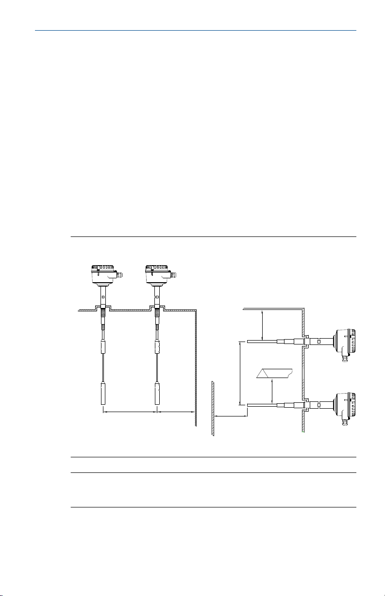
> 2 (50)
> 3.9
(100)
> 3.9
(100)
> 7.9
(200)
> 7.9 (200)
> 19.7 (500)
October 2020 Quick Start Guide
2.1.6 Orientation of cable glands
When the level switch is mounted horizontally, ensure the cable glands are
pointed downwards to avoid water getting inside the housing. Unused
conduit entries must be completely sealed with a suitably rated stopping
(blanking) plug.
2.1.7 Future maintenance
It is advisable to grease the screws of the housing cover (lid) when a
corrosive atmosphere is present. This will help prevent difficulties when the
cover needs to be removed during future maintenance tasks.
2.1.8 Minimum distances
Figure 2-2 shows the minimum distances required between installed level
switches, the walls of a silo, and a protective shield. The installation of a
protective angled shield above the level switch is recommended depending
on the type of bulk solids.
Figure 2-2: Minimum Distances
Note
Avoid installing the level switch directly under the flow of solids material
(filling point).
Quick Start Guide 11
Page 12

> 1.8
(50)
A
> 1.8
(50)
A
> 1.8
(50)
A
> 1.8
(50)
A
OK
OK OK
OK
E
F
G
C
D
B
Quick Start Guide October 2020
2.2 Mounting the level switch
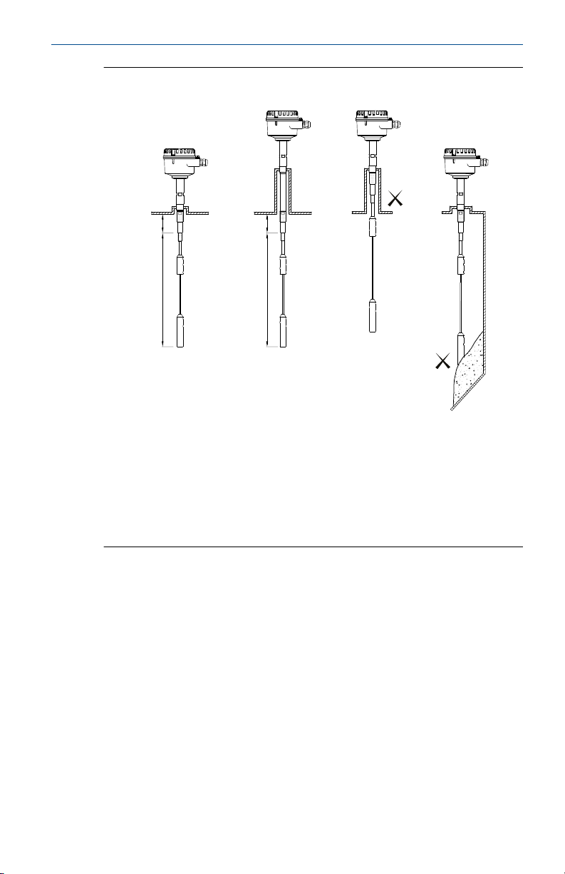
Figure 2-3 and Figure 2-4 show how the Rosemount 2555 should be
mounted.
Figure 2-3: Correct and Incorrect Mounting (Rod Version)
A. Active probe
B. Mounting the level switch at an angle helps solids material to fall away
and prevent build-up
C. Correct installation: The inactive length is correctly used with a long
socket
D. Correct installation: The inactive length is correctly used even though
there is a build-up of solids material
E. Incorrect installation: The active probe is inside the socket
F. Incorrect installation: The active probe is covered by a build-up of
material and is not detecting the true level
G. Incorrect installation: The active probe is located where solids material
would remain, even in an empty silo
12 Quick Start Guide
Page 13
> 1.8 (50) > 1.8 (50)
A A
OK
OK
B C D E
October 2020 Quick Start Guide
Figure 2-4: Correct and Incorrect Mounting (Rope Version)
A. Active probe
B. Correct installation: The socket height is short
C. Correct installation: The inactive length is correctly used within a long
socket
D. Incorrect installation: The active probe is inside the socket
E. Incorrect installation: The active probe is covered by a build-up of
material and may not be detecting the true level
Quick Start Guide 13
Page 14

Quick Start Guide October 2020
3 Electrical installation
3.1 Wiring considerations
Note
See the Rosemount 2555 Product Data Sheet for the full electrical
specifications.
3.1.1 Handling
In cases of improper handling or handling malpractice, the electrical safety
of the device cannot be guaranteed.
3.1.2 Grounding (earthing)
Before any electrical installation, connect the internal or external Potential
Earth (PE) terminal to a grounding point at the installation site if the
Rosemount 2555 is mounted to a non-metal silo or other storage vessel.
Note
See Wiring the level switch for the location of the PE terminals.
3.1.3 Installation regulations
Local regulations or VDE 0100 (Regulations of German Electrotechnical
Engineers) must be observed.
When using 24 V supply voltage, an approved power supply with reinforced
insulation to mains is required.
3.1.4 Fuse
Use a fuse as stated in the connection diagrams.
For details, see Wiring the level switch.
3.1.5 Residual Current Circuit Breaker (RCCB) protection
In case of a defect, the distribution voltage must automatically be cut-off by
an RCCB protection switch to protect against indirect contact with
dangerous voltages.
3.1.6 Power supply
Power supply switch
A voltage disconnection switch must be provided near the device.
Supply voltage
Compare the supply voltage applied with the specifications given on the
electronic module and nameplate before switching on the device.
14 Quick Start Guide
Page 15

October 2020 Quick Start Guide
3.1.7 Wiring
Field wiring cables
The diameter has to match the clamping range of the used cable gland.
The cross-section has to match the clamping range of the connection
terminals and the maximum current must be considered.
All field wiring must have insulation suitable for at least 250 Vac.
The temperature rating must be at least 194 °F (90 °C).
Use a shielded cable when there are electrical interferences present that are
higher than stated in the EMC standards. Otherwise, an unshielded
instrumentation cable can be used.
Guiding the cables in the terminal box
The field wiring cables must be cut to a length to be able to properly fit them
into the terminal box.
Connection terminals
When preparing cable wires for connection to terminals in a standard or type
'D' housing, the wire insulation must be stripped to show no more than 0.31
in. (8 mm) of the copper strands. For Type 'DE' housings, remove insulation
of no more than 0.35 in. (9 mm). Always check that the power supply is
disconnected or switched-off to avoid coming into contact with dangerous
live parts.
3.1.8 Cable glands
The screwed cable gland and stopping plug must have the following
specifications:
• Ingress protection IP67
• Temperature range from -40 °C to +80 °C
• Hazardous area certification (depending on where the unit is installed)
• Pull relief
Ensure the screwed cable gland safely seals the cable and is tight enough to
prevent water ingress. Unused conduit or cable entries must be sealed with a
stopping (blanking) plug.
A strain relief must be provided for the field wiring cables when the device is
installed with the factory-provided cable glands.
Cable glands and conduit system for ATEX or IECEx
The installation must comply with the regulations of the country where the
level switch is installed.
Quick Start Guide 15
Page 16

Quick Start Guide October 2020
Unused entries have to be closed with suitably rated stopping (blanking)
plugs.
Where available, the factory-provided parts must be used.
The diameter of the field wiring cable must match the clamping range of the
cable clamp.
If factory-provided parts are not used, the following must be ensured:
• The parts must have an approval adequate to the approval of the level
sensor (certificate and type of protection).
• The approved temperature range must be between the minimum
ambient temperature of the level sensor and the maximum ambient
temperature of the level sensor increased by 10 K.
• The parts must be mounted according to the instructions of the
manufacturer.
3.1.9 Conduit system
When a threaded conduit system is used instead of a cable gland, the
regulations of the country must be observed. The conduit must have a ½-in.
NPT tapered thread to match a NPT threaded conduit entry of the level
switch and comply with ANSI B 1.20.1. Unused conduit entries must be
closed tightly with a metal stopping (blanking) plug.
Conduit system for FM
The regulations of the country must be observed. The flameproof seals and
stopping (blanking) plugs must have an adequate type approval and a
temperature range of at least -40 to 176 °F (–40 to +80 °C). In addition, they
must be suitable for the conditions and correctly installed. Where available,
the original provided parts of the manufacturer must be used.
Installation with a conduit system in a hazardous area
In a conduit system, single electric conductors are installed in a certified pipe
system. This pipe system must also have a flameproof or explosion-proof
construction.
For ATEX and IECEx approvals, both enclosure of the level switch and pipe
system need to be isolated from each other by using a certified flameproof
or explosion-proof seal. The seal must be installed directly in, or at, the
conduit entries of the level switch. Unused conduit entries must be sealed
using suitably certified blanking elements (stopping plugs).
For FM approval, both enclosure of the level switch and pipe system need to
be isolated from each other by using a certified flameproof seal. The seal
must be installed within 18 inches of the enclosure wall. Unused conduit
entries must be sealed using suitably certified blanking elements (stopping
plugs).
16 Quick Start Guide
Page 17
1 1 2
3
4
5
6
7
8
B
C
A
October 2020 Quick Start Guide
3.1.10 Remote housing
The remote cable must be installed separately from the power supply lines
to avoid immunity interferences The minimum bending radius of 2 in. (50
mm) must be observed.
3.1.11 Relay and transistor protection
Provide protection for relay contacts and output transistors to protect the
device against inductive load surges.
3.1.12 Static charging
The Rosemount 2555 must be grounded to avoid a static electrical build-up.
This is particularly important for applications with pneumatic conveying and
non-metallic containers.
3.1.13 Opening the lid
Before opening the lid, ensure no dust deposits, no airborne dusts, and no
hazardous atmosphere are present.
Do not remove the lid (cover) in hazardous areas while circuits are alive.
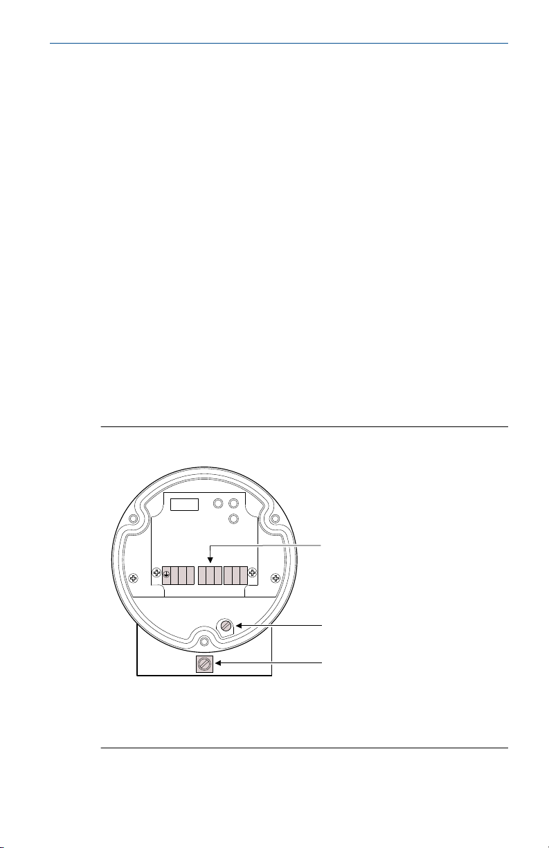
3.2 Wiring the level switch
Figure 3-1: Connections Overview for Standard Housing
A. Connection terminals
B. Internal Protective Earth (PE) terminal
Quick Start Guide 17
C. External Protective Earth (PE) terminal
Page 18
B
A
1
1
2
3
4
5
6
7
8
A
B
C
Quick Start Guide October 2020
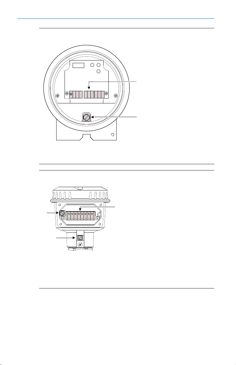
Figure 3-2: Connections Overview for Type 'D' Housing
A. Connection terminals
B. Internal Protective Earth (PE) terminal
Figure 3-3: Connections Overview for Type 'DE' Housing
A. Connection terminals (in a terminal box for increased safety).
The fixing torque is 0.5 to 0.6 Nm
B. Internal Protective Earth (PE) terminal
C. External Protective Earth (PE) terminal
18 Quick Start Guide
Page 19

1 1
2 3 456 7 8
PE
+
-
L N
A
B
October 2020 Quick Start Guide
3.2.1 Wiring the power supply and the DPDT relay
Power supply
• 21 to 230 Vac (50/60 Hz) ±10%, 1.5 VA
• 21 to 230 Vdc ±10%, 1.5 W
• Fuse on power supply: maximum 10 A, 250 V, HBC, fast or slow
Signal output (floating relay DPDT)
• Maximum 250 Vac, 8 A (non-inductive)
• Maximum 30 Vdc, 5 A (non-inductive)
• Fuse on signal output: maximum 10 A, 250 V, HBC, fast or slow
Figure 3-4: Power Supply and Signal Output
Quick Start Guide 19
A. Power supply
B. Signal output
Page 20
1 1 2 6 7 8 3 4 5
CAL
TEST
MENU
LED
Display
Quick Start Guide October 2020
4 Configuration
4.1 User interface
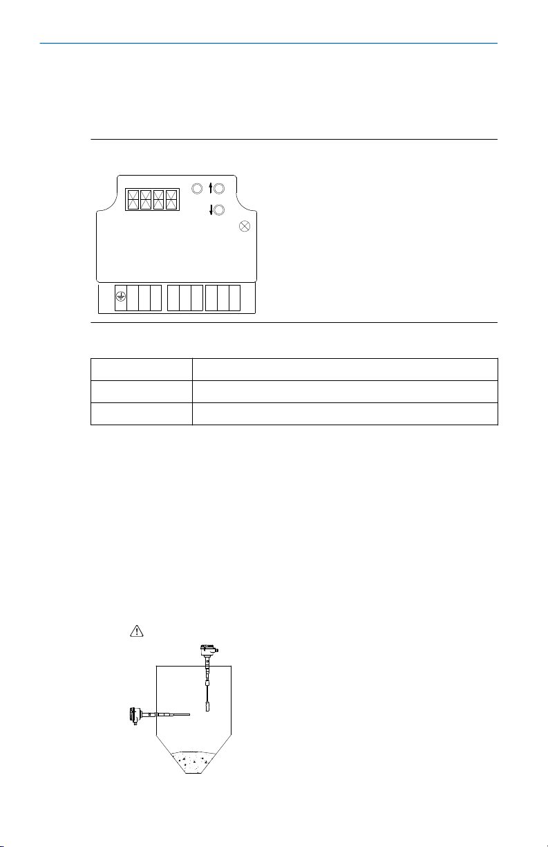
Figure 4-1: Features of the User Interface
Table 4-1: LEDs
Green Relay is energized
Yellow Relay is de-energized
Red Maintenance (flashing) or error (not flashing)
4.2 Powering up the first time (calibration)
Calibration automatically starts when the Rosemount 2555 is powered up
for the first time. If the level switch is powered off and then on again, this
calibration procedure is not repeated when starting up.
Prerequisites
• The level switch must be correctly mounted and wired.
• The level of the solids material must be below the probe.
Procedure
1. Ensure the level of the solids material is not covering the probe.
20 Quick Start Guide
Page 21
October 2020 Quick Start Guide
2. Power up the level switch.
a) The calibration is in progress when the displays indicate CAL
and the LED is red and flashing.
b) After approximately 45 seconds, the calibration completes
and indicates the actual measured capacitance and the letter
u is indicated for the uncovered probe status.
3. Check the quick-start settings.
a) Use the quick-start menu (see Quick-start menus) to review
and change the factory settings for Fail Safe High and Low,
signal output delay, and sensitivity.
Postrequisites
The Rosemount 2555 is now calibrated and ready to be configured.
4.3 Measurement mode
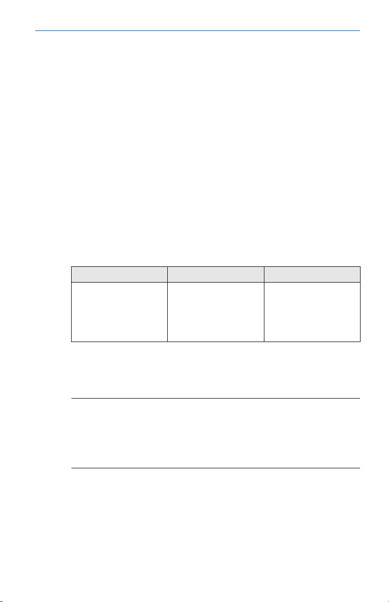
The level switch indicates the actual measured capacitance and the status of
the signal output.
(1)
Display
*** u
*** c
LED Description
Green or yellow
(2)
Actual measured
capacitance in pF
Actual signal output:
states uncovered probe u
or covered probe c.
(3)
.
(1) If unexpected messages are displayed, see Maintenance and error messages.
(2) Green or yellow depending on setting of FSH and FSL.
(3) Resolution is 0.1 pF (< 100 pF) or 0.5 pF (> 100 pF). If values are > 100 pF, a dot
behind the number means 0.5 pF (e.g. 100. means 100.5 pF)
Note
If the actual measured capacitance is higher than electronics can measure
(i.e. > 400 pF with sensitivity setting >= 2 pF or > 100 pF with sensitivity
setting <= 1 pF), the level switch will state 400c or 100c. The measurement
is valid, since the actual capacitance is well above the calibrated switch
point. Also, the output signal indicates the probe is covered by showing c.
Quick Start Guide 21
Page 22
MENU
CAL
TEST
Quick Start Guide October 2020
4.4 Quick-start menus
Note
The LED is flashing red while the quick-start menu is displayed. If no button is
pressed within 5 minutes, the unit automatically returns to the
measurement mode. All changed menu settings are saved.
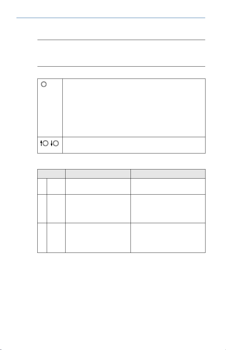
Table 4-2: In Measurement Mode
When the level switch is in Measurement mode, press and hold the
MENU button for 3 seconds to enter the quick-start menu. If Code is
displayed, a Lock Code is required. Set the code number with the arrow
buttons and confirm with the Menu button. Then press and hold the
Menu button again for 3 seconds to enter the quick-start menu.
While in the quick-start menu, press and hold the Menu button for 3
seconds to return to Measurement mode.
Press the Menu button for less than 1 second to store a new setting and
proceed to the next menu item.
Use the arrowed buttons, CAL and TEST, to increase and decrease the
value of a setting.
Table 4-3: Quick-start Menus
Display Description Menu item
FSL
C-U
U-C
2
5
to 60
(1)
Fail Safe High
Signal output, Fail safe setting
Fail Safe Low
(1)
Covered-to-uncovered-to-
Signal output, Delay direction
covered probe
Covered-to-uncovered probe
Uncovered-to-covered probe
(1)
Seconds Signal output, Delay time
Adjustable in steps (increment in 5
seconds).
A. FSH
B. ALL
C. 0.5
22 Quick Start Guide
Page 23

6 7 8 3 4 5 6 7 8 3 4 5 6 7 8 3 4 5 6 7 8 3 4 5 6 7 8 3 4 5
FSL FSH FSL FSH
Yellow LED Yellow LED Power failureGreen LED Green LED
October 2020 Quick Start Guide
Table 4-3: Quick-start Menus (continued)
Display Description Menu item
D. 0.5
1
2
4
10
15
25
35
(1) Factory default setting.
(2) Standard factory setting is 2 pF. Optional standard settings if ordered.
pF
(2)
Sensitivity
Required capacitance increase
between uncovered probe (after
calibration) and switch to output
covered probe.
Change the preset value only if
required by the application. See
Guide to push-button calibration.
The D menu item is not valid, and is
not shown if Manual calibration
(menu item G) is set to ON.
4.4.1 FSH and FSL settings
• FSH:
— Use the FSH setting for full-silo detection applications.
— Power failure or line break is considered by the electronics to be as
full signal (as protection against overfilling).
• FSL:
— Use the FSL setting for empty-silo detection applications.
— Power failure or line break is considered by the electronics to be as
empty signal (as protection against running dry).
Figure 4-2: FSH and FSL settings
Quick Start Guide 23
Page 24
Quick Start Guide October 2020
4.5 Guide to push-button calibration
Push-button calibration needs to be done if Power up calibration at first
time operation was not successful or the unit was changed to another
location or a significant change of DK was present after changing the
material.
Calibration with uncovered probe only This is the simplest method and,
Calibration with uncovered and covered
probe
therefore, is recommended.
If a too small change of capacitance
between uncovered and covered probe
is present, a higher sensitivity can be
selected (1 pF or 0.5 pf).
For a higher change of capacitance and
excessive build-up, the sensitivity can be
reduced (4 pF or more).
For the calibration procedure, see
Powering up the first time (calibration).
Sets the switching-point in the middle
between uncovered and covered probe
capacitances. It ensures the maximum
switching distance to both uncovered
and covered probe capacitance, and
helps to prevent material build-up.
For materials with low DK values and
therefore smaller capacitance
differences for covered and uncovered
states, this method is recommended.
The DK values are not required to be
known.
For the calibration procedure, see
Powering up the first time (calibration).
24 Quick Start Guide
Page 25
A C D
B
CAL
October 2020 Quick Start Guide
4.5.1 Push-button calibration for an uncovered probe only
Prerequisites
• The level switch must be correctly mounted and wired.
• The level of the solids material must be below the probe.
Procedure
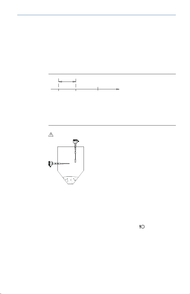
1. Review the stages in the calibration procedure.
A. Capacitance of uncovered probe
B. Sensitivity
C. Switching-point
D. Capacitance of covered probe
2. Ensure the solids material is not covering the probe.
Quick Start Guide 25
3. Set the sensitivity.
This is only required in certain circumstances. See Guide to push-
button calibration.
Use the quick-start menu item D to set the sensitivity. See Quick-
start menus.
Press and hold the CAL button for three seconds.
4.
The LED is red and flashing when the calibration is started.
a) Wait approximately 10 seconds until the calibration is
completed.
b) The display then indicates the actual measured capacitance
and a u for the uncovered probe state.
Page 26

Quick Start Guide October 2020
Need help?
If Code is displayed:
1. Enter the code using the arrow buttons and confirm it with the Menu
button.
2. Press and hold the CAL button again for three seconds to restart the
calibration.
If any other messages are displayed, see Maintenance and error messages.
Postrequisites
The Rosemount 2555 is now calibrated and ready to be configured.
26 Quick Start Guide
Page 27
A C D
B
CAL
October 2020 Quick Start Guide
4.5.2 Push-button calibration for uncovered and covered probes
Prerequisites
• The level switch must be correctly mounted and wired.
• The level of the solids material must be below the probe.
Procedure
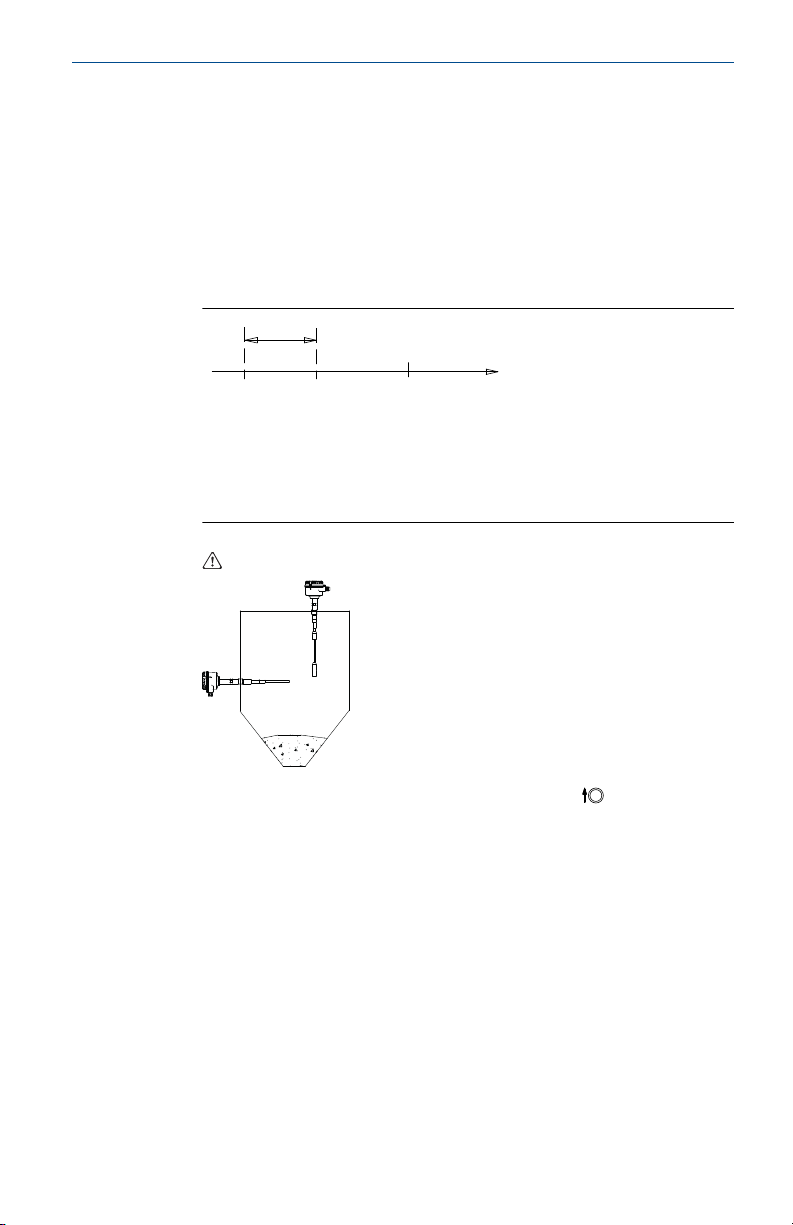
1. Review the stages in the calibration procedure.
A. Capacitance of uncovered probe
B. Sensitivity
C. Switching-point
D. Capacitance of covered probe
2. Ensure the solids material is not covering the probe.
Quick Start Guide 27
3. Press and hold the CAL button for three seconds.
The LED is red and flashing when the calibration is started.
a) Wait approximately 10 seconds until the calibration is
completed.
b) The display then indicates the actual measured capacitance
and a u for the uncovered probe state.
4. Make a note of the actual measured capacitance displayed when the
probe is uncovered.
5. Make a note of the actual measured capacitance displayed when the
probe is covered.
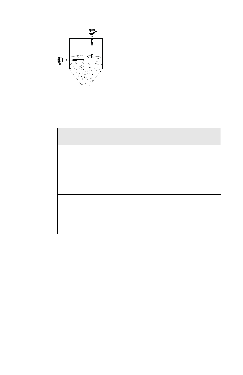
For vertical mounting (rope version), the solids material must cover
the probe by 4 - 8 in. (10 - 20 cm).
Page 28
Quick Start Guide October 2020
6. Set the sensitivity.
Calculate the capacitance difference between the uncovered and
covered probe.
Set the sensitivity as follows (quick-start menu item D):
Horizontal mounting Vertical mounting
(rope version)
Capacitance
0.8 to 1.5 pF 0.5 pF 0.5 to 1.0 pF 0.5 pF
1.5 to 3 pF 1 pF 1.0 to 2 pF 1 pF
3 to 6 pF 2 pF 2 to 4 pF 2 pF
6 to 15 pF 4 pF 4 to 10 pF 4 pF
15 to 23 pF 10 pF 10 to 15 pF 10 pF
23 to 38 pF 15 pF 15 to 25 pF 15 pF
38 to 53 pF 25 pF 25 to 35 pF 25 pF
> 53 pF 35 pF > 35 pF 35 pF
(1)
Sensitivity
(2)
Capacitance
(1)
Sensitivity
(3)
(1) Capacitance difference between uncovered and covered probe.
(2) The difference between uncovered and covered should be well above
the sensitivity setting, i.e. approximately > 50 percent.
(3) The difference between uncovered and covered does not need to be
above the sensitivity setting, since with the capacitance will increase
with rising solids material.
If different materials need to be measured in the same bin without
recalibration, the sensitivity must be set for the material with the
lowest DK.
Need help?
If Code is displayed:
1. Enter the code using the arrow buttons and confirm it with the Menu
button.
28 Quick Start Guide
Page 29

TEST
October 2020 Quick Start Guide
2. Press and hold the CAL button again for three seconds to restart the
calibration.
If any other messages are displayed, see Maintenance and error messages.
Postrequisites
The Rosemount 2555 is now calibrated and ready to be configured.
4.6 Resetting the first power-up calibration
An already calibrated level switch can be reset to perform a new power-up
calibration. This may be needed if installing it in a different silo or if it has to
be pre-configured before being shipped.
To do a reset:
1. Press and hold the CAL button for three seconds.
2. Switch off the voltage supply when CAL appears on the display.
Since the calibration was started, but not successfully finished, it
automatically starts again when the level switch is powered-up.
Note
Only the calibration is affected. The settings in the menus are not changed.
4.7 Data storage of the last valid calibration values
If the power supply is switched off, the last valid calibration values are
stored, and are still valid, when power is switched on again.
4.8
Quick Start Guide 29
Manual function test (proof test)
The Rosemount 2555 can self-test the internal electronics and external
connected signal evaluation.
Prerequisites
The proof-test must be operated in Measurement mode.
Procedure
1. Press and hold the TEST button for three seconds.
The display shows TEST when the testing is started.
2. Wait approximately 20 seconds until the test is completed.
During the test, the LED turns yellow and the signal output relay
changes state for approximately 10 seconds before returning to
normal operation.
Page 30
MENU
CAL
TEST
Quick Start Guide October 2020
Need help?
If Code is displayed:
1. Enter the code using the arrow buttons and confirm it with the Menu
button.
2. Press and hold the CAL button again for three seconds to restart the
calibration.
If ERR is displayed, see Maintenance and error messages.
Postrequisites
The Rosemount 2555 is now calibrated and ready to be configured.
4.9 Advanced menu
Note
The LED will be red and flashing while the menu is displayed. If no button is
pressed within 5 minutes, the unit automatically returns to the
measurement mode. All changed menu settings are saved.
Table 4-4: In Measurement Mode
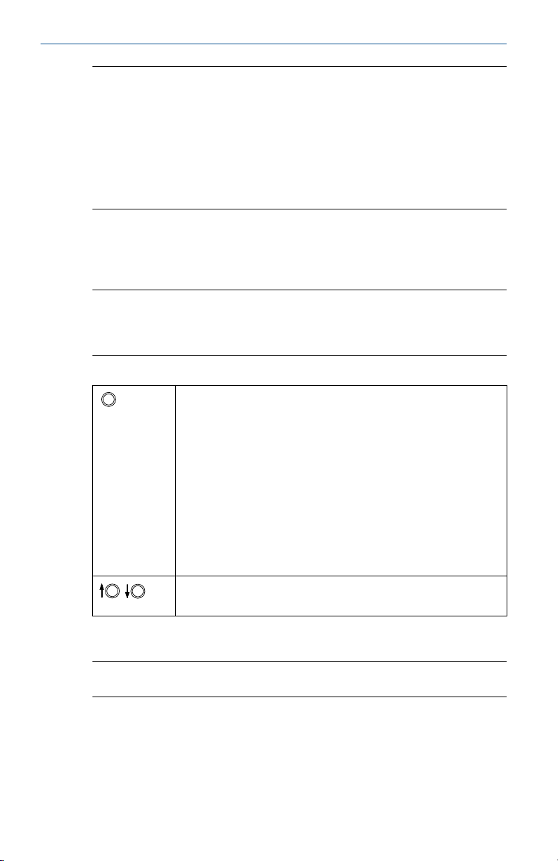
When the level switch is in Measurement mode, press and hold the
MENU button for 10 seconds to enter the Advanced menu. Keep
holding the MENU button even when the Quick-start menu (item:
A.FSx) appears after 3 seconds.
If Code is displayed, a Lock Code is required. Set the code number
with the arrow buttons, CAL and TEST, and confirm with the MENU
button. Then, press and hold the MENU button again for 10
seconds to enter the Advanced menu.
While in the Advanced menu, press and hold the menu button for
3 seconds to return to Measurement mode.
Press the MENU button for less than 1 second to store a new
setting and proceed to the next menu item.
Use the arrowed buttons, CAL and TEST, to increase and decrease
the value of a setting.
4.9.1 Auto recalibration
Note
The LED is red and flashing while the menu is displayed.
30 Quick Start Guide
Page 31
October 2020 Quick Start Guide
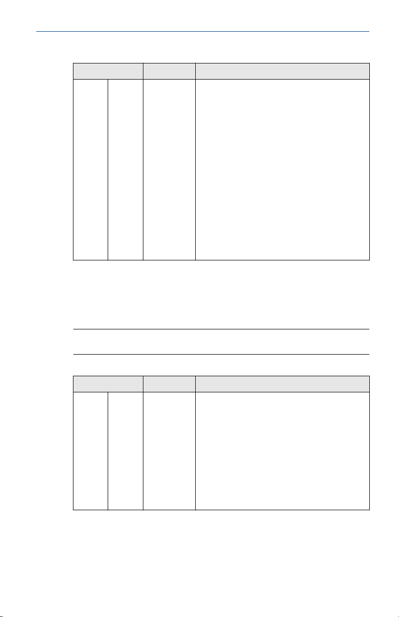
Table 4-5: Auto Recalibration Menu (Advanced Menu)
Display Description Menu item
(1)
F.
(1) Menu item "F" is not valid, and will not appear on the display, if manual
calibration (Menu item "G") is set to "ON".
(2) Factory default setting.
OFF
ON
(2)
Auto recalibration to uncovered probe.
It is possible to commission an already filled silo
(covered probe). A proper calibration is not
possible with covered probe. A solution is to do
an auto calibration as soon as the silo becomes
empty (uncovered probe).
To do this, set Auto recalibration to ON and do a
push-button calibration with a covered probe
(press and hold the CAL button for 3 seconds).
The level switch will recalibrate (as an uncovered
probe) when the measured capacitance is 50% of
the sensitivity setting (menu item D) for more
than two minutes.
Do not set to ON if excessive solids material
build-up is present, since this build-up may
decrease the measured capacitance and cause
an incorrect calibration.
4.9.2 Manual calibration
Note
The LED will be red and flashing while the menu is displayed.
Table 4-6: Manual calibration menu (Advanced menu)
Display Description Menu item
(1)
G.
OFF
ON
Manual calibration ON/OFF.
If set to ON:
• Menu items H,K and L appear.
• Menu items D (Quick-start menu) and F
(Auto re-calibration) are no longer valid and
are hidden.
• Push-button calibration is not possible (if
CAL button is pressed, the display shows
G.ON).
Quick Start Guide 31
Page 32
A C D E
B
Quick Start Guide October 2020
Table 4-6: Manual calibration menu (Advanced menu) (continued)
Display Description Menu item
(1)
H.
K. *** pF
L. *** pF
LO
HI
Low
High
Sensitivity range.
Low sensitivity range allows to detect a
capacitance change of ≥ 2 pF.
High sensitivity range allows to detect a
capacitance change of ≥ 0.5 pF.
See also Guide to manual calibration
Switching-point covered-to-uncovered
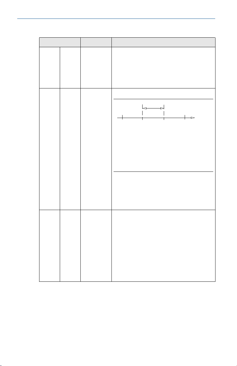
A. Capacitance of uncovered probe
B. Hysteresis (Menu item L)
C. Covered-to-uncovered switching-point (Menu
item "K")
D. Uncovered-to-covered switching-point
E. Capacitance of covered probe
Factory setting for the lowest pF value is 3 pF.
Resolution is 0.1 pF (< 100 pF) or 0.5 pF (> 100
pF). If values are > 100 pF, a dot behind the
number means 0.5 pF (e.g. 100. means 100.5
pF).
Hysteresis
Hysteresis can be adjusted to minimize constant
switching of the signal output. This can happen
when there are unstable capacitance
measurements due to movement of solids
materials.
The lowest value (factory setting) is 0.5/0.2 pF
(for Low/High sensitivity).
The maximum value is limited by the maximum
measurable capacitance.
For resolution, see menu item K.
(1) Factory default setting.
32 Quick Start Guide
Page 33
October 2020 Quick Start Guide
4.9.3 Diagnostics
Note
The LED is red and flashing while the menu is displayed.
Table 4-7: Diagnostics Menu (Advanced Menu)
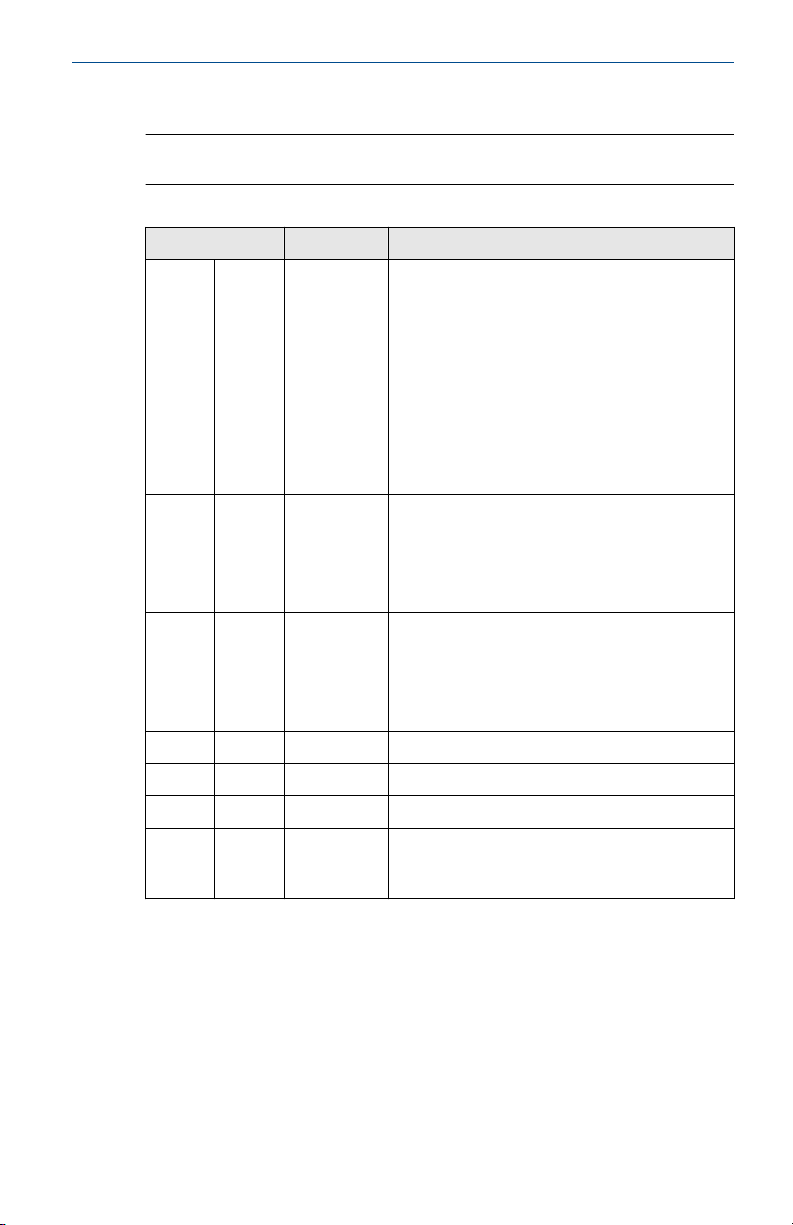
Display Description Menu item
OFF
(1)
Auto Function Test.
This function automatically tests the internal
electronics. Testing runs in the background and
does not affect the normal measurement
functions.
If a failure is detected:
• The display shows ERR. See Table 5-1.
• The LED turns red and starts flashing.
• The status output relay is de-energized.
M. ON
N. *** pF
P. *** pF
Q. *** °C
R. *** °C
S. ***
T. ***
(1) Factory default setting.
Auto calibrated switch-point (covered-touncovered).
If OR or UR is displayed, there is no valid
calibration.
See Troubleshooting.
Auto calibrated switching-point(uncovered-tocovered).
If OR or UR is displayed, there is no valid
calibration.
See Troubleshooting.
Minimum Stored Electronics Temperature
Maximum Stored Electronics Temperature
Software version
Service data
This manufacturer data is for the use of Emerson
and not covered in this manual.
Quick Start Guide 33
Page 34
Quick Start Guide October 2020
4.9.4 Security and factory reset
Note
The LED is red and flashing while the menu is displayed.
Table 4-8: Security and Factory Reset Menu (Advanced Menu)
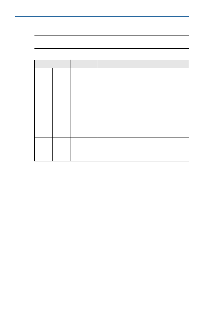
Display Description Menu item
V. *** Lock code.
The locking code (password) can be set to
prevent unauthorized persons from accessing
the menu system, starting a push-button
calibration, or a manual function test (proof
test).
The locking code can be any number from 1 to
9999.
A locking code of 000 disables the password
protection.
Contact Emerson if a locking code was set but
has been forgotten.
YES
(1)
Factory reset.
This resets all user-entered data to the factory
defaults. The level switch automatically starts a
calibration.
W. NO
(1) Factory default setting.
4.10 Guide to manual calibration
Manual calibration is recommended for special purposes.
Calibration with uncovered probe only
This is the simplest method and, therefore, is recommended. It is applicable
for higher DK values, which give a higher change of capacitance between an
uncovered and covered probe. The DK value of the solids material is required
to be known, to set the sensitivity range and an increase to the switchingpoint.
For the calibration procedure, see Powering up the first time (calibration).
Calibration with uncovered and covered probe
This method is the safest, since it sets the switching-point in the middle
between uncovered and covered probe capacitances. It ensures the
maximum switching distance to both uncovered and covered probe
capacitance, and helps prevent material build-up.
For materials with low DK values, and therefore smaller capacitance
differences for covered and uncovered states, this method is recommended.
34 Quick Start Guide
Page 35
A C E F
B D
October 2020 Quick Start Guide
The DK values are required only to be roughly known, so as to set the
sensitivity range.
For the calibration procedure, see Powering up the first time (calibration).
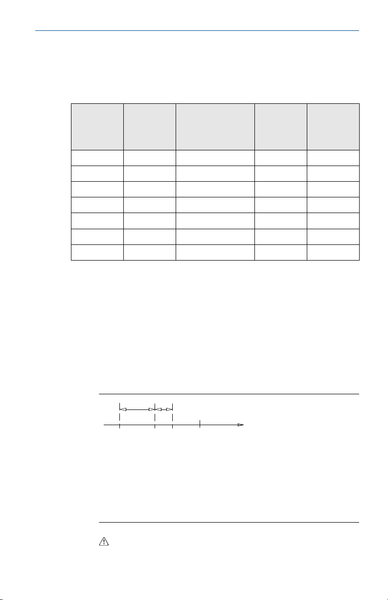
Table 4-9: Manual Calibration Guide
DK Sensitivity
range
< 1.5 - - - -
1.5 to 1.6 High - - Required
1.7 to 1.9 High Recommended +1 pF Possible
2.0 to 2.9 Low Recommended +2 pF Possible
3.0 to 4.9 Low Recommended +4 pF Possible
5.0 to 10 Low Recommended +10 pF Possible
> 10 Low Recommended +15 pF Possible
Calibration:
Uncovered probe
only
4.10.1 Manual calibration for an uncovered probe
Prerequisites
• The level switch must be correctly mounted and wired.
• The level of the solids material must be below the probe.
• The signal output delay should be set to 0.5 seconds.
Procedure
1. Review the stages in the calibration procedure.
Increase to
switchingpoint
Calibration:
Uncovered
and covered
probe
A. Capacitance of uncovered probe
B. Increase to switch-point
C. Switching-point for covered-to-uncovered probe
D. Hysteresis
E. Switching-point for uncovered-to-covered probe
F. Capacitance of covered probe
2. Ensure the level of the solids material is well below the probe.
Quick Start Guide 35
Page 36
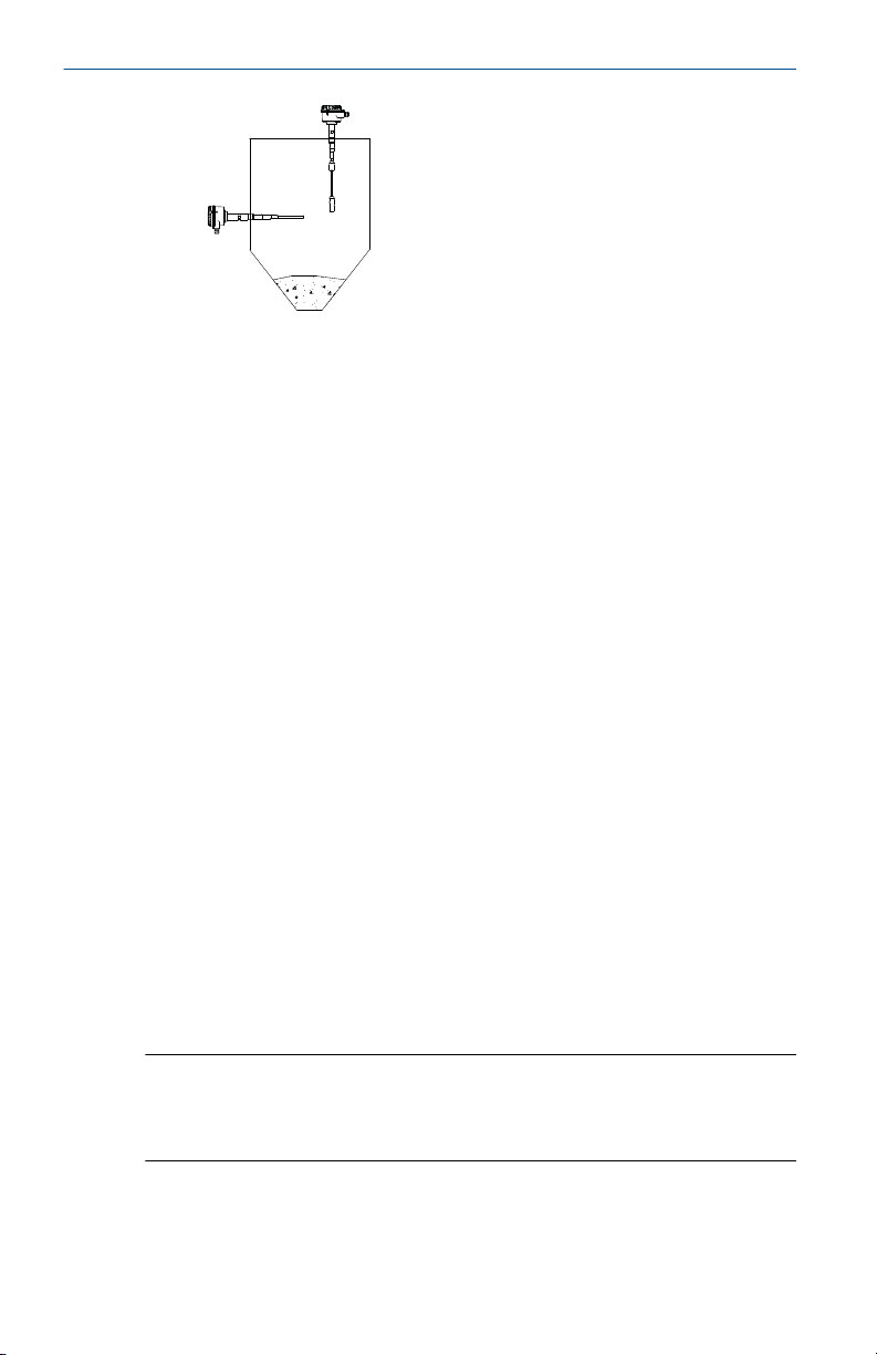
Quick Start Guide October 2020
3. Set the sensitivity.
Check for the required sensitivity range (low or high) depending on
the material to be measured. Use the calibration guide. See Guide to
manual calibration.
Use the Advanced menu item H to set the sensitivity. See Advanced
menu.
4. Establish the capacitance of the uncovered probe.
a) Navigate to the menu item K in the Advanced menu.
b) Starting with the lowest capacitance (factory setting is 3 pF),
increase the displayed capacitance until the output just
changes from covered to uncovered states.
In measurement mode, the actual measured capacitance is
displayed. This gives an indication of which capacitance the output
changes from a covered to uncovered state.
If the output has once changed to uncovered and changes back to
covered, the value must be decreased by setting the Hysteresis
(menu item L).
5. Set a switch-point for the covered-to-uncovered change.
Use the Advanced menu item K to set the switch-point to the
established capacitance of an uncovered probe + an increase to the
switch-point. See Advanced menu.
6. Set the Hysteresis.
Use the Advanced menu item L to set the hysteresis. The factory
setting is normally sufficient and does not need to be changed.
Need help?
If the actual measured capacitance is close to the limits of what the
electronic can measure (400 pF with sensitivity setting Low or 100 pF with
sensitivity setting High). See Maintenance and error messages.
Postrequisites
The Rosemount 2555 is now calibrated and ready to be used.
36 Quick Start Guide
Page 37
A BCD E
50% 50%
October 2020 Quick Start Guide
4.10.2 Manual calibration for uncovered and covered probes
Prerequisites
• The level switch must be correctly mounted and wired.
• The level of the solids material must be below the probe.
• Manual calibration must be set to ON (Advanced menu, item K)
Procedure
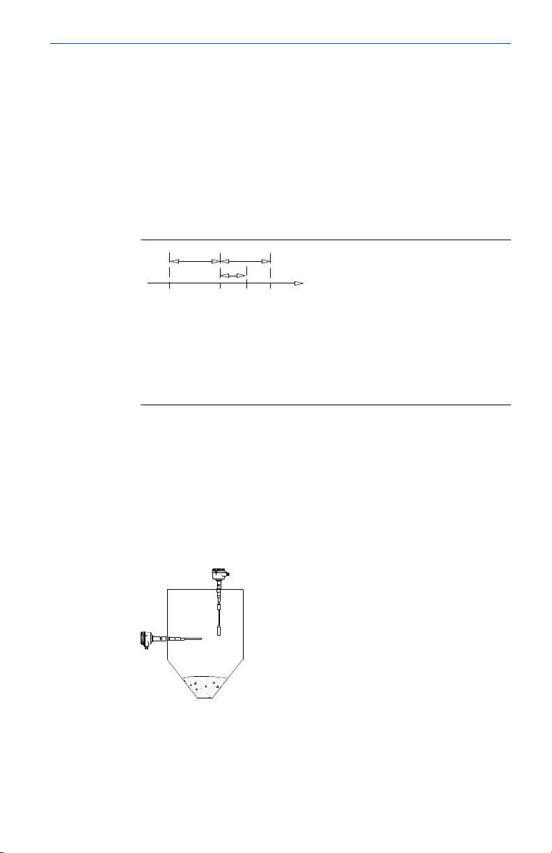
1. Review the stages in the calibration procedure.
A. Capacitance of uncovered probe
B. Switching-point for covered-to-uncovered probe
C. Hysteresis
D. Switching-point for uncovered-to-covered probe
E. Capacitance of covered probe
2. Set the sensitivity.
Check for the required sensitivity range (low or high) depending on
the material to be measured. Use the calibration guide. See Guide to
manual calibration.
Use the Advanced menu item H to set the sensitivity. See Advanced
menu.
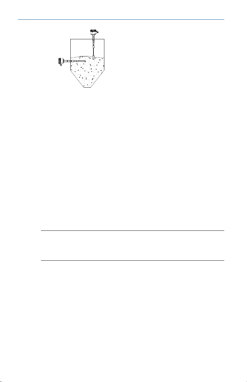
3. Make a note of the actual measured capacitance displayed when the
probe is uncovered.
4. Make a note of the actual measured capacitance displayed when the
probe is covered.
For vertical mounting (rope version), the solids material must cover
the probe by 4 to 8 in. (10 to 20 cm).
Quick Start Guide 37
Page 38
Quick Start Guide October 2020
5. Set a switch-point for the covered-to-uncovered change.
Use the Advanced menu item K to set the switch point to:
(Capacitance
uncovered
(0.5 * (Capacitance
+
covered
- Capacitance
uncovered
))
With Low sensitivity range (Advanced menu item H): If the difference
between uncovered and covered probe is smaller than 4 pF, set
either to High sensitivity or use a more sensitive probe (longer active
probe). For rope version only a setting to High sensitivity range is
possible.
With High sensitivity range (Advanced menu item H): If the
difference between uncovered and covered probe is smaller than 1
pF, use a more sensitive probe (longer active probe). For rope
version, call factory.
6. Set the Hysteresis.
Use the Advanced menu item L to set the hysteresis. The factory
setting is normally sufficient and does not need to be changed.
Need help?
If the actual measured capacitance is close to the limits of what the
electronic can measure (400 pF with sensitivity setting Low or 100 pF with
sensitivity setting High). See Maintenance and error messages.
Postrequisites
The Rosemount 2555 is now calibrated and ready to be configured.
38 Quick Start Guide
Page 39
October 2020 Quick Start Guide
5 Troubleshooting
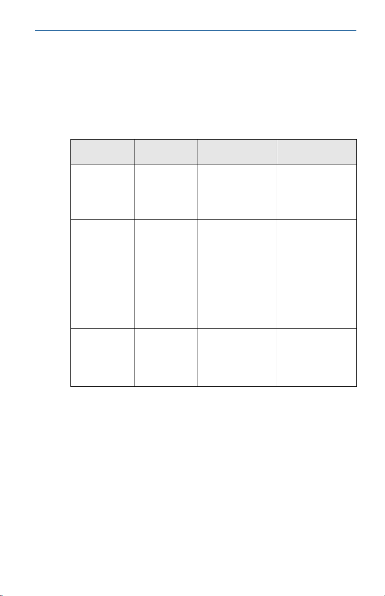
5.1 Maintenance and error messages
The level switch indicates error messages while in measurement mode and
during calibration routines.
Table 5-1: In Measurement Mode
Display LED Description Possible causes and
UR Flashing red Under Range
Actual measured
capacitance is lower
than 3 pF.
OR Flashing red Over Range
After changing the
sensitivity from ≥ 2 pF
to ≤ 1 pF.
ERR Constant red Auto or Manual
Function Test error
solutions
Probe is defective or
the probe is
incorrectly wired.
The signal output
relay is de-energized.
Actual calibrated
capacitance is higher
than 100 pF and
cannot be measured
with Sensitivity
setting ≤ 1 pF.
Change to Sensitivity
2 pF (if DK of the
material is high
enough) or
recalibrate.
Electronics fault.
Replace the
electronics.
The output signal
relay is de-energized.
Quick Start Guide 39
Page 40
Quick Start Guide October 2020
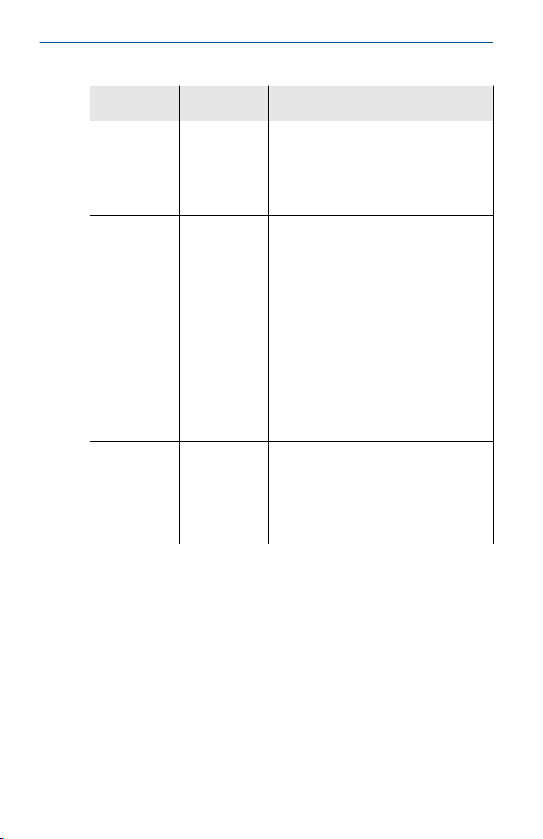
Table 5-2: During Power-up or Push-button Calibration
Display LED Description Possible causes and
UR Flashing red Under Range
Actual measured
capacitance is lower
than 3 pF.
Calibration is not
possible.
OR Flashing red Over Range.
Actual measured
capacitance is higher
than 400 pF
(sensitivity setting ≥ 2
pF) or 100 pF
(sensitivity setting ≤ 1
pF).
Calibration is not
possible.
G.ON Flashing red CAL button pressed
with Manual
calibration set to ON.
Starting a calibration
using the push
button is not
possible.
solutions
Probe is defective or
the probe is
incorrectly wired.
The signal output
relay is de-energized.
A long rope version in
an empty silo may
exceed 100 pF
capacitance. Change
Sensitivity setting to
2 pF if DK of the
material is high
enough.
Probe may be
covered with
material. Ensure that
the probe is
uncovered.
The probe may be
faulty or incorrectly
wired.
Set Manual
calibration to OFF
when the push
button is to be used
for starting a
calibration.
40 Quick Start Guide
Page 41
October 2020 Quick Start Guide
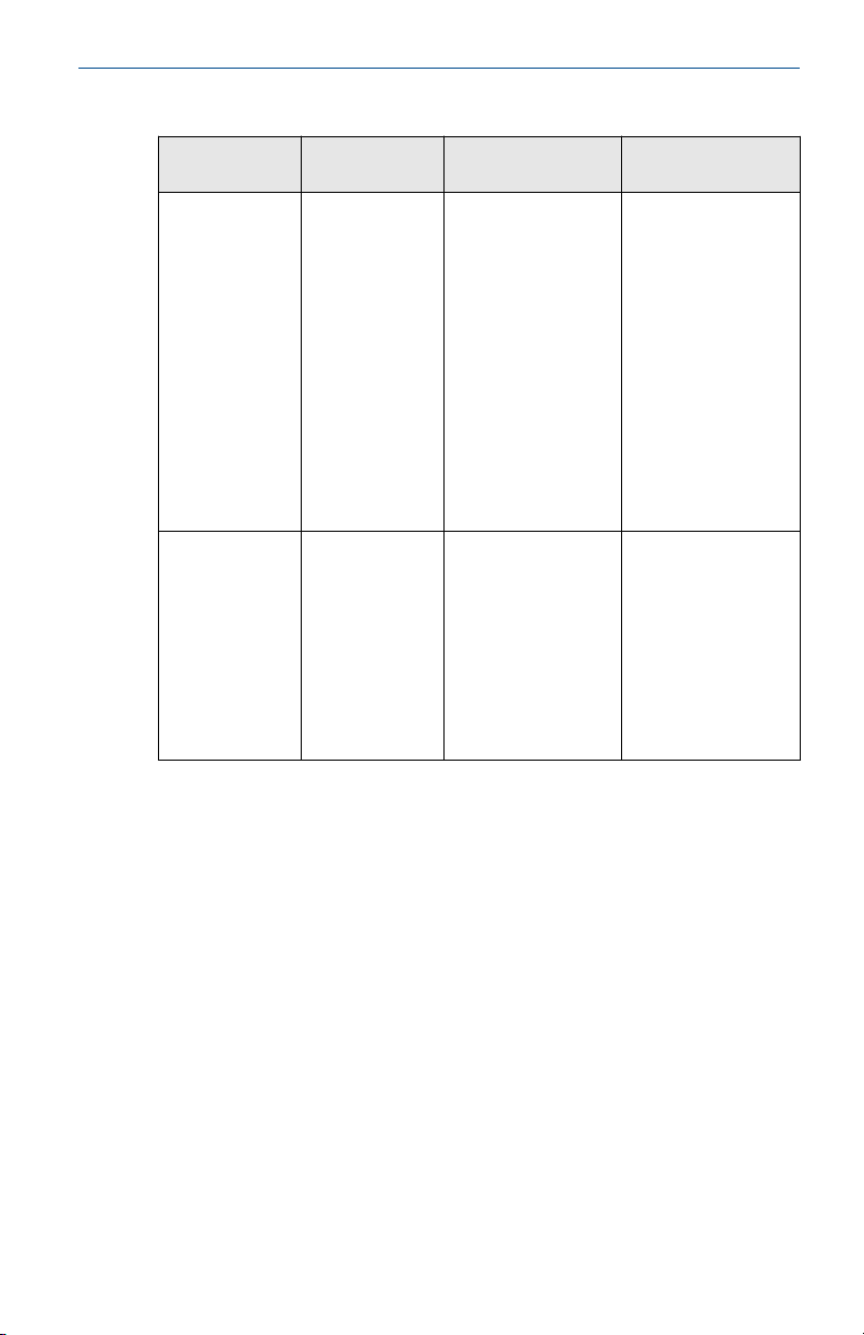
Table 5-3: During Manual Calibration
Display LED Description Possible causes and
solutions
(1)
100
Yellow or green With the sensitivity
range set to high.
Actual measured
capacitance is close
to, or higher than,
100 pF (depending on
the capability of
electronics).
Calibration not
possible.
A long rope version in
an empty silo may
exceed 100 pF
capacitance. Change
the sensitivity range
to low if DK of the
material is high
enough.
Probe may be
covered with
material. Ensure that
probe is uncovered.
The probe may be
faulty or incorrectly
wired.
(2)
400
Yellow or green With the sensitivity
range set to low.
Actual measured
capacitance is close
to, or higher than,
400 pF (depending on
capability of
electronics).
Probe may be
covered with
material. Ensure that
the probe is
uncovered.
The probe may be
faulty or incorrectly
wired.
Calibration is not
possible.
(1) The display is showing 100 or close to 100.
(2) The display is showing 400 or close to 400.
Quick Start Guide 41
Page 42
Quick Start Guide October 2020
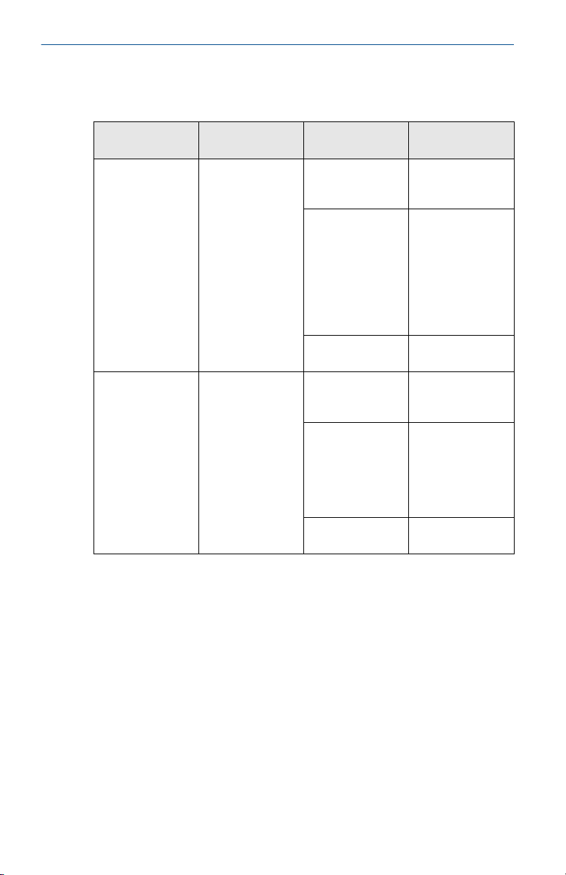
5.2 General items
Table 5-4: General Items
Situation Behavior of the
electronic
Signal output state
is 'probe covered'
even though the
solids material is
below the probe.
The actual
measured
capacitance
(1)
greater than the
calibrated
switching-point
for an uncoveredto-covered probe
change of state.
Signal output state
is 'uncovered
probe' even though
the solids material
is above the probe.
The actual
measured
capacitance
less than the
calibrated
(3)
switching-point
for an covered-touncovered probe
change of state.
Possible reason Possible solution
The level switch is
Recalibrate.
not properly
is
calibrated.
Excessive material
build-up on active
(2)
probe.
Increase distance
to wall (longer
inactive length).
Change the
installation
location.
Recalibrate with
less sensitivity
Faulty or incorrect
probe wiring.
Calibration was
Check the probe
wiring (see below).
Recalibrate
done with covered
is
probe.
Calibration was
performed with a
(4)
sensitivity that was
too low.
Recalibrate with
higher
sensitivity
Increase active
probe length and
recalibrate
Faulty or incorrect
probe wiring.
Check the probe
wiring (see below).
(3)
(3)
.
(3)
.
(3)
.
(3)
.
(1) The value can be seen on the display in Measurement mode.
(2) The value can be seen in Advanced menu item P.
(3) See the calibration guides.
(4) The value can be seen in Advanced menu item N.
42 Quick Start Guide
Page 43
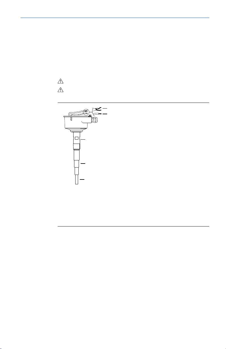
A
B
C
D
E
October 2020 Quick Start Guide
5.3 Check the probe wiring
Prerequisites
The power supply to the level switch must be switched off.
Procedure
1. Clean away any deposits on the probe.
2. Take out the electronic board and disconnect internal wires.
3.
Check the orange, yellow, and green/yellow wires with a
multimeter.
A. Orange (probe) and yellow (shield)
B. Green/yellow (ground)
C. Ground
D. Shield
E. Probe
Less than 5 Ohm must be present between:
• Orange wire and probe
• Yellow wire and shield
• Green/yellow wire and ground
More than 1 MΩ resistance must be present between:
• Orange and yellow wires
• Orange and green/yellow wires
If other values are present, the wiring of the probe is incorrect or
defective.
Quick Start Guide 43
Page 44

Quick Start Guide October 2020
6 Maintenance
6.1 Opening the lid (cover)
Before opening the lid for maintenance reasons, consider the following:
• Do not remove the lid in a hazardous area while circuits are live.
• Ensure that no dust deposits or airborne dusts are present.
• Ensure that rain does not enter the housing.
6.2 Regular checks for safety
To ensure robust safety in hazardous locations and with electrical safety, the
following items must be regularly checked depending on the application:
• Mechanical damage or corrosion of the field wiring cables or any other
components (housing side and sensor side).
• Tight sealing of the process connection, cable glands, and enclosure lid.
• Properly connected external PE cable (if present).
6.3 Cleaning
If cleaning is required by the application, following must be observed:
• Cleaning agent must comply with the materials of the unit (chemical
resistance). Mainly the shaft sealing, lid sealing, cable gland and the
surface of the unit must be considered.
The cleaning process must be done in a way, that:
• The cleaning agent cannot enter into the unit through the shaft sealing,
lid sealing or cable gland.
• No mechanical damage of the shaft sealing, lid sealing, cable gland or
other parts can happen.
Note
An accumulation of dust on the housing does not increase the surface
temperature. However, dust can be safely removed with a damp cloth.
Never use a dry cloth because it may cause an electrostatic discharge. See
the Rosemount 2555 Product Certifications document for the maximum
surface temperatures in hazardous area (classified locations) applications.
6.4
44 Quick Start Guide
Function test
Depending on the application, frequent functional testing may be required.
See Manual function test (proof test) for details.
Page 45

October 2020 Quick Start Guide
6.5 Production date
The production year is shown on the nameplate.
6.6 Spare parts
Refer to the Rosemount 2555 Product Data Sheet for all spare parts.
Quick Start Guide 45
Page 46

Quick Start Guide October 2020
46 Quick Start Guide
Page 47

October 2020 Quick Start Guide
Quick Start Guide 47
Page 48
*00825-0100-2555*
00825-0100-2555, Rev. AC
Quick Start Guide
October 2020
Emerson Automation Solutions
6021 Innovation Blvd.
Shakopee, MN 55379, USA
+1 800 999 9307 or +1 952 906 8888
+1 952 949 7001
[email protected]
Latin America Regional Office
Emerson Automation Solutions
1300 Concord Terrace, Suite 400
Sunrise, FL 33323, USA
+1 954 846 5030
+1 954 846 5121
[email protected]
Asia Pacific Regional Office
Emerson Automation Solutions
1 Pandan Crescent
Singapore 128461
+65 6777 8211
+65 6777 0947
[email protected]
North America Regional Office
Emerson Automation Solutions
8200 Market Blvd.
Chanhassen, MN 55317, USA
+1 800 999 9307 or +1 952 906 8888
+1 952 949 7001
[email protected]
Europe Regional Office
Emerson Automation Solutions Europe
GmbH
Neuhofstrasse 19a P.O. Box 1046
CH 6340 Baar
Switzerland
+41 (0) 41 768 6111
+41 (0) 41 768 6300
[email protected]
Middle East and Africa Regional Office
Emerson Automation Solutions
Emerson FZE P.O. Box 17033
Jebel Ali Free Zone - South 2
Dubai, United Arab Emirates
+971 4 8118100
+971 4 8865465
[email protected]
Linkedin.com/company/Emerson-
Automation-Solutions
Twitter.com/Rosemount_News
Facebook.com/Rosemount
Youtube.com/user/
RosemountMeasurement
©
2020 Emerson. All rights reserved.
Emerson Terms and Conditions of Sale are
available upon request. The Emerson logo is a
trademark and service mark of Emerson Electric
Co. Rosemount is a mark of one of the Emerson
family of companies. All other marks are the
property of their respective owners.
 Loading...