

Page 1

Rosemount™ 248 Temperature
Transmitter
Quick Start Guide
00825-0100-4825, Rev JB
April 2019
Page 2

Quick Start Guide
April 2019
NOTICE
This guide provides basic guidelines for the Rosemount 248. It does not provide instructions for detailed
configuration, diagnostics, maintenance, service, troubleshooting, or installations. Refer to the Rosemount
248 Reference Manual
Emerson.com/Rosemount
Explosions could result in death or serious injury.
Installation of this transmitter in an explosive environment must be in accordance with the appropriate local,
national, and international standards, codes, and practices. Review the Hazardous Locations Certifications for
any restrictions associated with a safe installation.
Process leaks may cause harm or result in death.
Install and tighten thermowells or sensors before applying pressure.
Do not remove the thermowell while in operation.
Electrical shock can result in death or serious injury.
Avoid contact with the leads and terminals. High voltage that may be present on leads can cause electrical
shock.
Unless marked, the conduit/cable entries in the transmitter housing use a
marked “M20” are M20 3 1.5 thread form. On devices with multiple conduit entries, all entries have the
same thread form. Only use plugs, adapters, glands, or conduit with a compatible thread form when
closing entries.
When installing in a Hazardous Location, use only appropriately listed or Ex certified plugs, adapters or
glands in cable/conduit entries.
for more instruction. The manual and this guide are also available electronically on
.
1
/2–14 NPT thread form. Entries
Contents
Configure (bench calibration) . . . . . . . . . . . . . . 3
Mount the transmitter . . . . . . . . . . . . . . . . . . . . 5
Connect the wiring . . . . . . . . . . . . . . . . . . . . . . . 9
2
Perform a loop test . . . . . . . . . . . . . . . . . . . . . . 12
Product Certifications . . . . . . . . . . . . . . . . . . . 13
Page 3

April 2019
A
B
C
D
1.0 Configure (bench calibration)
The Rosemount 248 can be configured in three ways: a Field Communicator, the
Rosemount 248 PC Programming Kit, or custom configured at the factory using
the C1 option code.
Refer to the Rosemount 248 Reference Manual
Reference Manual
1.1 Connecting a Field Communicator
The Field Communicator Field Device Revision Dev v1, DD v1or later is required
for complete functionality.
Figure 1. Connecting a Field Communicator to a Bench Loop
for more information.
Quick Start Guide
and the Field Communicator
A. Rosemount 248 Transmitter
B. 250 Ω ≤ R
≤ 1100 Ω
L
Note
Do not operate when power is below 12 Vdc at the transmitter terminal.
1.2 Verify transmitter configuration
To verify operation using a Field Communicator, refer to the Fast Keys below.
Refer to the Rosemount 248 Reference Manual for more detailed description.
Function Fast Keys Fun ction Fast Keys
Active calibrator 1, 2, 2, 1, 3 Poll addr ess 1, 3, 3, 3, 1
Alarm/saturation 1, 3, 3, 2 Process temperature 1, 1
AO alarm type 1, 3, 3, 2, 1 Process variables 1, 1
Burst mode 1, 3, 3, 3, 3 PV damping 1, 3, 3, 1, 3
Burst option 1, 3, 3, 3, 4 PV unit 1, 3, 3, 1, 4
Calibration 1, 2, 2 Range values 1, 3, 3, 1
Configuration 1, 3 Review 1, 4
C. Field Communicator
D. Power supply
3
Page 4

Quick Start Guide
Function Fast Keys Function Fas t Keys
D/A trim 1, 2, 2, 2 Scaled D/A trim 1, 2, 2, 3
Damping values 1, 1, 10 Sensor connection 1, 3, 2, 1, 1
Date 1, 3, 4, 2 Sensor 1 setup 1, 3, 2, 1, 2
Descriptor 1, 3, 4, 3 Sensor serial number 1, 3, 2, 1, 3
Device out put configuration 1, 3, 3 Sensor 1 trim-factory 1, 2, 2, 1, 2
Diagnostics and service 1, 2 Sensor type 1, 3, 2, 1, 1
Filter 50/60 Hz 1, 3, 5, 1 Soft ware revision 1, 4, 1
Hardware rev 1, 4, 1 Status 1, 2, 1, 4
Intermittent detect 1, 3, 5, 4 Ter min al t emp erat ure 1, 3, 2, 2,
Loop test 1, 2, 1, 1 Tes t dev ice 1, 2, 1
LRV (Lower Range Value) 1, 1, 6 URV (Upper Range Value) 1, 1, 7
LSL (Lower Sensor Limit) 1, 1, 8 USL (Upper Sensor Limit) 1, 1, 9
Measurem ent filtering 1, 3, 5 Variable m apping 1, 3, 1
Message 1, 3, 4, 4 Variable re-map 1, 3, 1, 3
Num req preams 1, 3, 3, 3, 2 Write protect 1, 2, 3
Open sensor holdoff 1, 3, 5, 3 2-wire offset 1, 3, 2, 1, 2, 1
Percent range 1, 1, 5
For devices following the new device dashboard, refer to the Fast Keys below:
April 2019
Function Fast Keys Function Fast Keys
Active calibrator 3, 4, 1, 3 Poll Address 2, 2, 4, 1
Alarm saturation 2, 2, 2, 5 Process temperature 1, 3
AO alarm type 2, 2, 2, 5 Process variables 3, 2, 1
Burst mode 2, 2, 4, 2 PV damping 2, 2, 1, 6
Calibration 3, 4, 1, 1 PV unit 2, 2, 1, 4
Configuration 2, 2, 2, 4 Range values 2, 2, 2, 4
D/A trim 3, 4 Scaled D/A trim 3, 4, 3
Damping values 2, 2, 1, 6 Sensor connection 2, 2, 1, 3
Date 2, 2, 3, 1, 2 Sensor 1 set up 2, 1, 1
Descriptor 2, 2, 3, 1, 4 Sensor serial number 1, 7, 1, 4
Device Info 1, 7 Sensor 1 trim 3, 4, 1, 1
Device out put configuration 2, 2, 2, 4 Sensor 1 trim- factory 3, 4, 1, 2
Filter 50/60 Hz 2, 2, 3, 7, 1 Sensor type 2, 2, 1, 2
Hardware rev 1, 7, 2, 3 Sof tware revision 1, 7, 2, 4
HART® output 1, 7, 2, 1 Status 1, 1
Loop test 3, 5, 1 Ta g 2, 2, 3, 1,1
LVR (Lower Range Value) 2, 2, 2, 4, 3 Te rmi nal temp era tur e 3, 3, 2
4
Page 5

April 2019
Function Fast Keys Function Fas t Keys
LSL (Lower Sensor Limit) 2, 2, 1, 9 URV (Upper Range Value) 2, 2, 2, 4, 2
Message 2, 2, 3,1,3 USL (Upper Sensor Limit) 2, 2, 1, 8
Open sensor holdoff 2, 2, 3, 4 Write protect 2, 2, 3, 6
Percent range 2, 2, 2, 3 2-wire offset 2, 2, 1, 5
1.3 Rosemount 248 PC Programmer Kit installation
1. Install all necessary software for Rosemount 248 PC configuration:
a. Install the Rosemount 248C software.
Place the Rosemount 248C CD-ROM in the drive.
Run setup.exe from Windows
b. Install the MACTek
®
HART Modem drivers completely before beginning
bench configuration with the Rosemount 248 PC Programming system.
Note
For USB modem: Upon first use, configure appropriate COM ports within the Rosemount
248PC software by selecting Port Settings from the Commu nicate menu. The USB modem
driver emulates a COM port and will add to available port selections in the software’s
drop-down box. Otherwise software defaults to first available COM port, which may not be
correc t.
2. Set up configuration system hardware:
a. Hook up the transmitter and load resistor (250–1100 ohms) wired in
series with the power supply (the Rosemount 248 device will need an
external power supply of 12–42.4 Vdc for configuration).
b. Attach the HART modem in parallel with the load resistor and connect it
to the PC.
See Table 1 for spares kit and re-order numbers. For more information, refer to
the Rosemount 248 Reference Manual
Table 1. Programming Kit Spare Part Numbers
™
NT, 2000, or XP.
.
Quick Start Guide
Product description Part number
Programming software (CD) 00248-1603-0002
Rosemount 248 programmer kit - USB 00248-1603-0003
Rosemount 248 programmer kit - Serial 00248-1603-0004
2.0 Mount the transmitter
Mount the transmitter at a high point in the conduit run to prevent moisture
from draining into the transmitter housing.
2.1 Typical European and Asia Pacific installation
Head mount transmitter with DIN plate style sensor
1. Attach the thermowell to the pipe or process container wall. Install and
tighten the thermowell before applying process pressure.
5
Page 6

Quick Start Guide
AB C
D
EF
2. Assemble the transmitter to the sensor. Push the transmitter mounting
screws through the sensor mounting plate and insert the snap rings
(optional) into the transmitter mounting screw groove.
3. Wire the sensor to the transmitter.
4. Insert the transmitter-sensor assembly into the connection head. Thread the
transmitter mounting screw into the connection head mounting holes.
Assemble the extension to the connection head. Insert the assembly into the
thermowell.
5. Slip the shielded cable though the cable gland.
6. Attach a cable gland into the shielded cable.
7. Insert the shielded cable leads into the connection head through the cable
entry. Connect and tighten the cable gland.
8. Connect the shielded power cable leads to the transmitter power terminals.
Avoid contact with sensor leads and sensor connections.
9. Install and tighten the connection head cover.
Note
Enclosure covers must be fully engaged to meet explosion-proof requirements.
April 2019
A. Rosemount 248 Transmitter
B. Connection head
C. Thermowell
D. Transmitter mounting screws
E. Integral mount sensor with flying leads
F. E xt ension
2.2 Typical North and South American installation
Head mount transmitter with threaded sensor
1. Attach the thermowell to the pipe or process container wall. Install and
tighten thermowell before applying process pressure.
2. Attach necessary extension nipples and adapters to the thermowell. Seal the
nipple and adapter threads with silicone tape.
3. Screw the sensor into the thermowell. Install drain seals if required for severe
environments or to satisfy code requirements.
4. Pull the sensor wiring leads through the universal head and transmitter.
Mount the transmitter in the universal head by threading the transmitter
mounting screws into the universal head mounting holes.
6
5. Mount the transmitter-sensor assembly into the thermowell. Seal adapter
threads with silicone tape.
Page 7

April 2019
AB
D
C
E
A
B
C
Quick Start Guide
6. Install conduit for field wiring to the conduit entry of the universal head. Seal
conduit threads with silicone tape.
7. Pull the field wiring leads through the conduit into the universal head. Attach
the sensor and power leads to the transmitter. Avoid contact with other
terminals.
8. Install and tighten the universal head cover.
Note
Enclosure covers must be fully engaged to meet explosion-proof requirements.
A. Threaded thermowell
B. Threaded style sensor
C. Standard extension
D. Universal head
E. Conduit entry
2.3 Mounting to a DIN rail
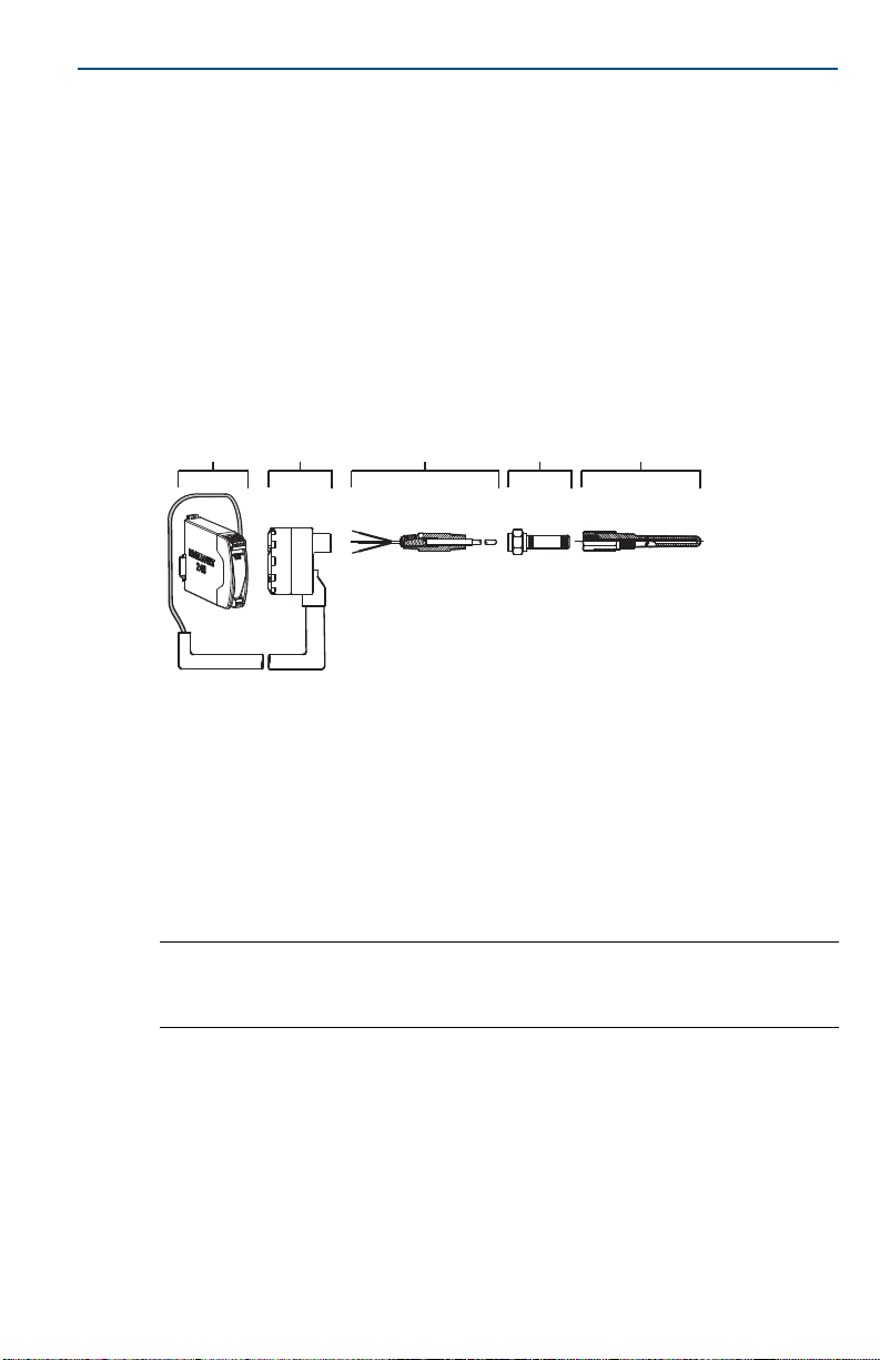
To attach the Rosemount 248H to a DIN rail, assemble the appropriate rail
mounting kit (part number 00248-1601-0001) to the transmitter as shown.
A. Mounting hardware
B. Transmitter
C. Rail clip
Rail mount transmitter with remote mount sensor
The least complicated assembly uses:
a remote mounted transmitter
an integral mount sensor with terminal block
an integral style connection head
a standard extension
a threaded thermowell
7
Page 8

Quick Start Guide
Refer to the Metric Sensor Product Data Sheet for complete sensor and
mounting accessory information.
To complete the assembly, follow the procedure described below.
1. Attach the transmitter to a suitable rail or panel.
2. Attach the thermowell to the pipe or process container wall. Install and
tighten the thermowell before applying pressure.
3. Attach the sensor to the connection head and mount the entire assembly to
the thermowell.
4. Attach sufficient lengths of sensor lead wire to the sensor terminal block.
5. Attach and tighten the connection head cover. Enclosure covers must be fully
engaged to meet explosion-proof requirements.
6. Run sensor lead wires from the sensor assembly to the transmitter.
7. Attach the sensor and power leads to the transmitter. Avoid contact with
leads and terminals.
April 2019
A
B
A. Rail mount transmitter
B. Sensor leads with cable gland
C. Integral mount sensor with terminal block
C
D
E
F
D. Connection head
E. Standard extension
F. T hr eade d t herm ow ell
Rail mount transmitter with threaded sensor
The least complicated assembly uses:
a threaded sensor with flying heads
a threaded sensor connection head
a union and nipple extension assembly
a threaded thermowell
Refer to Rosemount Sensor Product Data Sheet
mounting accessory information.
To complete the assembly, follow the procedure described below.
1. Attach the transmitter to a suitable rail or panel.
2. Attach the thermowell to the pipe or process container wall. Install and
tighten the thermowell before applying pressure.
for complete sensor and
8
Page 9
April 2019
Quick Start Guide
3. Attach necessary extension nipples and adaptors. Seal the nipple and adapter
threads with silicone tape.
4. Screw the sensor into the thermowell. Install drain seals if required for severe
environments or to satisfy code requirements.
5. Screw the connection head to the sensor.
6. Attach the sensor lead wires to the connection head terminals.
7. Attach additional sensor lead wires from the connection head to the
transmitter.
8. Attach and tighten the connection head cover. Enclosure covers must be fully
engaged to meet explosion-proof requirements.
9. Attach the sensor and power leads to the transmitter. Avoid contact with
leads and terminals.
A B C D E
A. Rail mount transmitter
B. Threaded sensor connection head
C. Threaded style sensor
3.0 Connect the wiring
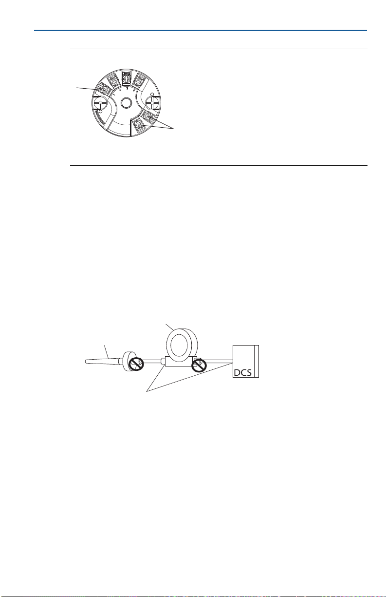
Wiring diagrams are located on the top label of the transmitter.
An external power supply is required to operate the transmitter.
The power required across the transmitter power terminals is 12 to 42.4 Vdc
(the power terminals are rated to 42.4 Vdc).
Note
To prevent damaging the transmitter, do not allow terminal voltage to drop below 12.0
Vdc when changing the configuration parameters.
3.1 Power the transmitter
1. Connect the positive power lead to the “+” terminal. Connect the negative
power lead to the “–” terminal.
2. Tighten the terminal screws.
3. Apply power (12–42 V dc).
D. Standard ex tension
E. Threaded thermowell
9
Page 10
Quick Start Guide
A
B
+
–
Figure 2. Power, Communication, and Sensor Terminals
A. Sensor terminals
B. Power/communication terminals
3.2 Ground the transmitter
Ungrounded thermocouple, mV, and RTD/Ohm inputs
Each process installation has different requirements for grounding. Use the
grounding options recommended by the facility for the specific sensor type, or
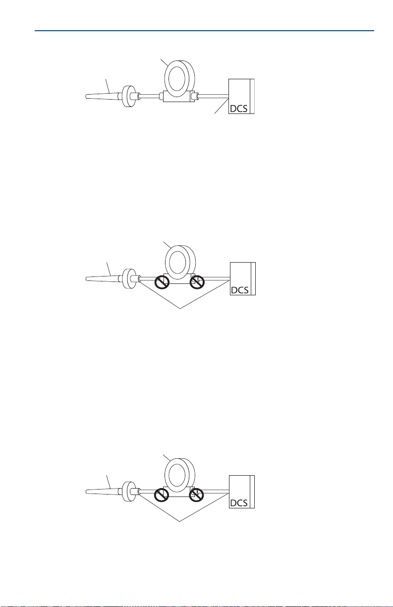
begin with grounding Option 1 (the most common).
Option 1 (for grounded housing)
1. Connect sensor wiring shield to the transmitter housing.
2. Ensure the sensor shield is electrically isolated from surrounding fixtures that
may be grounded.
3. Ground signal wiring shield at the power supply end.
B
April 2019
A
A. Sensor wires
B. Transmitter
D
C. 4–20 mA loop
D. Shield ground point
C
Option 2 (for ungrounded housing)
1. Connect signal wiring shield to the sensor wiring shield.
2. Ensure the two shields are tied together and electrically isolated from the
transmitter housing.
3. Ground shield at the power supply end only.
4. Ensure the sensor shield is electrically isolated from the surrounding
grounded fixtures.
5. Connect shields together, electrically isolated from the transmitter.
10
Page 11
April 2019
A
B
D
C
Quick Start Guide
B
A
A. Sensor wires
B. Transmitter
C. 4–20 mA loop
D. Shield ground point
C
D
Option 3 (for grounded or ungrounded housing)
1. Ground sensor wiring shield at the sensor, if possible.
2. Ensure the sensor wiring and signal wiring shields are electrically isolated
from the transmitter housing.
3. Do not connect the signal wiring shield to the sensor wiring shield.
4. Ground signal wiring shield at the power supply end.
A. Sensor wires
B. Transmitter
C. 4–20 mA loop
D. Shield ground point
Option 4 (for grounded thermocouple inputs)
1. Ground sensor wiring shield at the sensor.
2. Ensure the sensor wiring and signal wiring shields are electrically isolated
from the transmitter housing.
3. Do not connect the signal wiring shield to the sensor wiring shield.
4. Ground signal wiring shield at the power supply end.
B
A
A. Sensor wires
B. Transmitter
D
C. 4–20 mA loop
D. Shield ground point
C
11
Page 12

Quick Start Guide
4.0 Perform a loop test
The loop test command verifies transmitter output, loop integrity, and
operation of any recorders or similar devices installed in the loop.
Note
This is not available with the Rosemount 248C Configuration Interface.
4.1 Initiate a loop test
1. Connect an external ampere meter in series with the transmitter loop (so the
power to the transmitter goes through the meter at some point in the loop.
2. From the Home screen, select: 1) Device Setup > 2) Diag/Serv > 1) Test
Device > 1) Loop Test.
3. Select a discrete milliampere level for the transmitter to output. At Choose
Analog Output, select: 1) 4 mA > 2) 20 mA, or select 3) Other to manually
input a value between 4 and 20 milliamperes.
4. Select Enter to show the fixed output.
5. Select OK.
6. In the test loop, check that the fixed mA input and the transmitter’s mA
output are the same value.
April 2019
Note
If the readings do not match, either the transmitter requires an output trim or the current
meter is malfunctioning.
After completing the test, the display returns to the loop test screen and allows
the user to choose another output value.
4.2 End the loop test
1. Select 5) End.
2. Select Enter.
12
Page 13

April 2019
5.0 Product Certifications
Rev 1.20
5.1 European Directive Information
A copy of the EU Declaration of Conformity can be found at the end of the Quick Start
Guide. The most recent revision of the EU Declaration of Conformity can be found at
Emerson.com/Rosemount.
5.2 Ordinary Location Certification
As standard, the transmitter has been examined and tested to determine that the design
meets the basic electrical, mechanical, and fire protection requirements by a nationally
recognized test laboratory (NRTL) as accredited by the Federal Occupational Safety and
Health Administration (OSHA).
5.3 North America
The US National Electrical Code® (NEC) and the Canadian Electrical Code (CEC) permit the
use of Division marked equipment in Zones and Zone marked equipment in Divisions. The
markings must be suitable for the area classification, gas, and temperature class. This
information is clearly defined in the respective codes.
5.4 USA
E5 USA Explosionproof
Certificate: 3016555
Standards: FM Class 3600:2011, FM Class 3611:2004, FM Class 3615:2006, FM Class
3810:2005, ANSI/ISA 60079-0:2009, ANSI/ISA 60079-11:2009, IEC
60529: 2004, NEMA
Markings: XP CL I, DIV 1, GP B, C, D; DIP CL II/III, DIV 1, GP E, F, G); NI CL1, DIV 2, GP A,
B, C, D when installed per Rosemount drawing 00248-1065; Type 4;
®
– 250: 1991
Quick Start Guide
I5 FM Intrinsic Safety
Certificate: 3016555
Standards: FM Class 3600:2011, FM Class 3610:2010, FM Class 3611:2004, FM Class
Markings: IS CL I/II/III, DIV 1, GP A, B, C, D, E, F, G; NI CL1, DIV 2, GP A, B, C, D when
5.5 Canada
I6 Canada Intrinsically Safe
Certificate: 1091070
Standards: CAN/CSA C22.2 No. 0-10, CSA Std. C22.2 No. 25-1966, CAN/CSA C22.2
Markings: IS CL I, DIV 1 GP A, B, C, D when installed per Rosemount drawing
3810:2005, ANSI/ISA 60079-0:2009, ANSI/ISA 60079-11:2009, IEC
60529: 2004, NEMA – 250: 1991
installed per Rosemount drawing 00248-1055; Type 4X; IP66/68
No. 94-M91, CAN/CSA C22.2 No. 157-92, CSA C22.2 No. 213-M1987,
C22.2 No 60529-05
00248-1056; CL I DIV 2 GP A, B, C, D; Type 4X, IP66/68
13
Page 14

Quick Start Guide
K6 CSA Intrinsically Safe, Explosionproof, and Class 1, Division 2
Certificate: 1091070
Standards: CAN/CSA C22.2 No. 0-10, CSA Std. C22.2 No. 25-1966, CSA Std. C22.2
Markings: XP CL I/II/III, DIV 1, GP B, C, D, E, F, G when installed per Rosemount
5.6 Europe
E1 ATEX Flameproof
Certificate: FM12ATEX0065X
Standards: EN 60079-0: 2012+A11:2013, EN 60079-1: 2014, EN 60529:1991
Markings: II 2 G Ex db IIC T6…T1 Gb, T6(–50 °C ≤ T
See Tab l e 2 at the end of the Product Certifications section for process temperatures.
Specific Conditions of Use (X):
1. See certificate for ambient temperature range.
2. The non-metallic label may store an electrostatic charge and become a source of
ignition in Group III environments.
3. Guard the LCD display cover against impact energies greater than 4 joules.
4. Flameproof joints are not intended for repair.
5. A suitable certified Ex d or Ex tb enclosure is required to be connected to temperature
probes with Enclosure option “N”.
6. Care shall be taken by the end user to ensure that the external surface temperature on
the equipment and the neck of DIN Style Sensor probe does not exceed 130 °C.
7. Non-Standard Paint options may cause risk from electrostatic discharge. Avoid
installations that cause electrostatic build-up on painted surfaces, and only clean the
painted surfaces with a damp cloth. If paint is ordered through a special option code,
contact the manufacturer for more information.
April 2019
No. 30-M1986, CAN/CSA C22.2 No. 94-M91, CSA Std. C22.2
No.142-M1987, CAN/CSA C22.2 No. 157-92, CSA C22.2 No. 213-M1987,
C22.2 No 60529-05
drawing 00248-1066; IS CL I, DIV 1 GP A, B, C, D when installed per
Rosemount drawing 00248-1056; CL I DIV 2 GP A, B, C, D; Type 4X,
IP66/68 Conduit Seal not required.
+A1:2000+A2:2013
≤ +40 °C), T5…T1(–50 °C ≤ Ta
≤ +60 °C)
a
14
I1 AT EX I ntr ins ic S afety
Certificate: Baseefa03ATEX0030X
Standards: EN 60079-0: 2012, EN 60079-11: 2012
Markings: II 1 G Ex ia IIC T5/T6 Ga, T5(–60 °C ≤ T
+60 °C)
≤ +80 °C), T6(–60 °C ≤ Ta ≤
a
See Tab l e 3 at the end of the Product Certifications section for entity parameters.
Special Condition for Safe Use (X):
1. The apparatus must be installed in an enclosure which affords it a degree of protection
of at least IP20. Non-metallic enclosures must have a surface resistance of less than
1 GΩ; light allow or zirconium enclosures must be protected from impact and friction
when installed.
N1 ATEX Type n – with enclosure
Certificate: BAS00ATEX3145
Standards: EN 60079-0:2012+A11:2013, EN 60079-15:2010
Markings: II 3 G Ex nA IIC T5 Gc (–40 °C ≤ T
≤ +70 °C)
a
Page 15

April 2019
Quick Start Guide
NC ATEX Type n – without enclosure
Certificate: Baseefa13ATEX0045X
Standards: EN 60079-0:2012, EN 60079-15:2010
Markings: II 3 G Ex nA IIC T5/T6 Gc,T5(-60 °C ≤ T
+70 °C)
≤ +80 °C),T6(-60°C ≤ Ta ≤
a
Special Condition for Safe Use (X):
1. The Model 248 Temperature Transmitter must be installed in a suitably certified
enclosure such that it is afforded a degree of protection of at least IP54 in accordance
with IEC 60529 and EN 60079-15.
ND AT EX Dust
Certificate: FM12ATEX0065X
Standards: EN 60079-0: 2012+A11:2013, EN 60079-31:2014, EN 60529:1991
+A1:2000 +A2:2013
Markings: II 2 D Ex tb IIIC T130 °C Db, (–40 °C ≤ T
See Ta bl e 2 at the end of the Product Certifications section for process temperatures.
≤ +70 °C); IP66
a
Specific Conditions of Use (X):
1. See certificate for ambient temperature range.
2. The non-metallic label may store an electrostatic charge and become a source of
ignition in Group III environments.
3. Guard the LCD display cover against impact energies greater than 4 joules.
4. Flameproof joints are not intended for repair.
5. A suitable certified Ex d or Ex tb enclosure is required to be connected to temperature
probes with Enclosure option “N”.
6. Care shall be taken by the end user to ensure that the external surface temperature on
the equipment and the neck of DIN Style Sensor probe does not exceed 130 °C.
7. Non-Standard Paint options may cause risk from electrostatic discharge. Avoid
installations that cause electrostatic build-up on painted surfaces, and only clean the
painted surfaces with a damp cloth. If paint is ordered through a special option code,
contact the manufacturer for more information.
5.7 International
E7 ECEx Flameproof
Certificate: IECEx FMG 12.0022X
Standards: IEC 60079-0:2011, IEC 60079-1:2014-06, 60079-31:2013
Markings: Ex db IIC T6…T1 Gb, T6(–50 °C ≤ T
+60 °C);Ex tb III C T130C Db T
See Ta bl e 2 at the end of the Product Certifications section for process temperatures.
Specific Conditions of Use (X):
1. See certificate for ambient temperature range.
2. The non-metallic label may store an electrostatic charge and become a source of
ignition in Group III environments.
3. Guard the LCD display cover against impact energies greater than 4 joules.
4. Flameproof joints are not intended for repair.
5. A suitable certified Ex d or Ex tb enclosure is required to be connected to temperature
probes with Enclosure option “N”.
6. Care shall be taken by the end user to ensure that the external surface temperature on
the equipment and the neck of DIN Style Sensor probe does not exceed 130 °C.
7. Non-Standard Paint options may cause risk from electrostatic discharge. Avoid
installations that cause electrostatic build-up on painted surfaces, and only clean the
painted surfaces with a damp cloth. If paint is ordered through a special option code,
contact the manufacturer for more information.
≤ +40 °C), T5…T1(–50 °C ≤ Ta ≤
a
= –40 °C to +70 °C; IP66
a
15
Page 16

Quick Start Guide
I7 ECEx Intrinsic Safety
Certificate: IECEx BAS 07.0086X
Standards: IEC 60079-0:2011, IEC 60079-11:2011
Markings: Ex ia IIC T5/T6 Ga, T5(–60 °C ≤ T
See Tab l e 3 at the end of the Product Certifications section for entity parameters.
Special Condition for Safe Use (X):
1. The apparatus must be installed in an enclosure which affords it a degree of protection
of at least IP20. Non-metallic enclosures must have a surface resistance of less than
1 GΩ; light allow or zirconium enclosures must be protected from impact and friction
when installed.
N7 IECEx Type n – with enclosure
Certificate: IECEx BAS 07.0055
Standards: IEC 60079-0:2011, IEC 60079-15:2010
Markings: Ex nA IIC T5 Gc; T5(–40 °C ≤ T
NG IECEx Type n – without enclosure
Certificate: IECEx BAS 13.0029X
Standards: IEC 60079-0:2011, IEC 60079-15:2010
Markings: Ex nA IIC T5/T6 Gc; T5(–60 °C ≤ T
Special Condition for Safe Use (X):
1. The Model 248 Temperature Transmitter must be installed in a suitably certified
enclosure such that it is afforded a degree of protection of at least IP54 in accordance
with IEC 60529 and IEC 60079-15.
5.8 China
E3 NEPSI Flameproof
Certificate: GYJ16.1335X
Standards: GB3836.1-2010, GB3836.2-2010
Markings: Ex d IIC T6
Special Conditions for Safe Use (X):
1. Ambient temperature range is: T6…T1(–50 °C ≤ T
+60 °C).
2. The earth connection facility in the enclosure should be connected reliably.
3. During installation, there should be no mixture harmful to flameproof housing.
4. During installation in hazardous location, cable glands, conduits and blanking plugs,
certified by state-appointed inspection bodies with Ex d IIC Gb degree, should be used.
5. During installation, use and maintenance in explosive gas atmospheres, observe the
warning “Do not open when energized”.
6. End user is not permitted to change any components inside, but to settle the problem
in conjunction with manufacturer to avoid damage to the product.
7. When installation, use and maintenance of this product, observe the following
standards:
GB3836.13-2013 “Electrical apparatus for explosive gas atmospheres Part 13: Repair
and overhaul for apparatus used in explosive gas atmospheres”.
GB3836.15-2000 “Electrical apparatus for explosive gas atmospheres Part 15:
Electrical installations in hazardous area (other than mines)”.
GB3836.16-2006 “Electrical apparatus for explosive gas atmospheres Part 16:
Inspection and maintenance of electrical installation (other than mines).
GB50257-2015 “Code for construction and acceptance of electric device for explosion
atmospheres and fire hazard electrical equipment installation engineering”.
16
+60 °C)
April 2019
≤ +80 °C), T6(–60 °C ≤ Ta ≤ +60 °C)
a
≤ +70 °C)
a
≤ +80 °C), T6(–60 °C ≤ Ta ≤ +60 °C)
a
T1 Gb: T6…T1(–50 °C ≤ Ta ≤ +40 °C) T5…T1 (–50 °C ≤ Ta ≤
~
≤ +40 °C) T5…T1 (–50 °C ≤ Ta ≤
a
Page 17
April 2019
Quick Start Guide
I3 NEPSI Intrinsic Safety
Certificate: GYJ16.1334X
Standards: GB3836.1-2010, GB3836.4-2010, GB3836.20-2010
Markings: Ex ia IIC T5/T6 Ga; T5(–60 °C ≤ T
See Ta bl e 3 at the end of the Product Certifications section for entity parameters.
≤ +80 °C), T6(–60 °C ≤ Ta ≤ +60 °C)
a
Special Conditions for Safe Use (X):
1. Symbol “X” is used to denote specific conditions of use:
a. The enclosure may contain light metal, attention should be taken to avoid ignition
hazard due to impact or friction.
b. The apparatus must be installed in an enclosure which affords it a degree of
protection of at least IP20. Non-metallic enclosures must have a surface resistance of
less than 1 GΩ.
2. The relation between T code and ambient temperature range is:
T code Tem per atu re r ang e
T6 –60 °C ≤ T
T5 –60 °C ≤ T
≤ +60 °C
a
≤ +80 °C
a
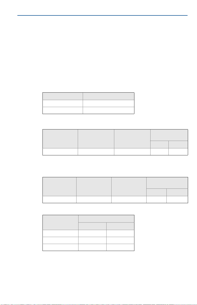
3. Intrinsically Safe parameters:
HART loop terminals (+ and –)
Maximum input
voltage U
(V)
i
30 130 1.0 3.6 0
Maximum input
current I
(mA)
i
Maximum input
power: P
(W)
i
Maximum internal
parameters
Ci (nF) Li (mH)
The above supply must be derived from a linear supply.
Sensor terminals (1 to 4)
Maximum output
voltage U
o
45 26 290 2.1 0
(V)
Maximum output
current I
(mA)
o
Maximum output
power: P
(mW)
o
Maximum internal
parameters
Ci (nF) Li (mH)
Sensor terminals (1 to 4)
Group
IIC 23.8 23.8
IIB 237.9 87.4
IIA 727.9 184.5
Maximum external parameters
Co (nF) Lo (mH)
4. The product should be used with Ex-certified associated apparatus to establish
explosion protection system that can be used in explosive gas atmospheres. Wiring
and terminals should comply with the instruction manual of the product and
associated apparatus.
17
Page 18

Quick Start Guide
5. The cables between this product and associated apparatus should be shielded cables
(the cables must have insulated shield). The shielded has to be grounded reliably in
non-hazardous area.
6. End user is not permitted to change any components inside, but to settle the problem
in conjunction with manufacturer to avoid damage to the product.
7. When installation, use and maintenance of this product, observe the following
standards:
GB3836.13-1997 “Electrical apparatus for explosive gas atmospheres Part 13: Repair
and overhaul for apparatus used in explosive gas atmospheres”.
GB3836.15-2000 “Electrical apparatus for explosive gas atmospheres Part 15:
Electrical installations in hazardous area (other than mines)”.
GB3836.16-2006 “Electrical apparatus for explosive gas atmospheres Part 16:
Inspection and maintenance of electrical installation (other than mines)”.
GB50257-1996 “Code for construction and acceptance of electrical device for
explosion atmospheres and fire hazard electrical equipment installation engineering.
N3 NEPSI Type n
Certificate: GYJ15.1089
Standards: GB3836.1-2010, GB3836.8-2003
Markings: Ex nA nL II C T5 Gc (–40 °C ≤ T
Special Condition for Safe Use (X):
1. See certificate for special conditions.
5.9 EAC
EM Technical Regulation Customs Union (EAC) Flameproof
Certificate: TC RU C-US.AA87.B.00057
Markings: 1Ex d IIC T6…T1 Gb X, T6(–50 °C ≤ T
Special Condition for Safe Use (X):
1. See certificate for special conditions.
+60 °C); IP66/IP67
≤+70 °C)
a
≤ +40 °C), T5…T1(–50 °C ≤ Ta ≤
a
April 2019
IM Technical Regulation Customs Union (EAC) Intrinsic Safety
Certificate: TC RU C-US.AA87.B.00057
Markings: 0Ex ia IIC T5,T6 Ga X, T6(–60 °C ≤ T
IP66/IP67
Special Condition for Safe Use (X):
1. See certificate for special conditions.
5.10 Korea
EP Korea Explosionproof/Flameproof
Certificate: 13-KB4BO-0208X
Markings: Ex d IIC T6; T6(–40 °C ≤ T
Special Condition for Safe Use (X):
1. See certificate for special conditions.
5.11 Combinations
K5 Combination of E5 and I5
KM Combination of EM and IM
18
≤ +65 °C)
amb
≤ +60 °C), T5(–60 °C ≤ Ta ≤ +80 °C);
a
Page 19
April 2019
Quick Start Guide
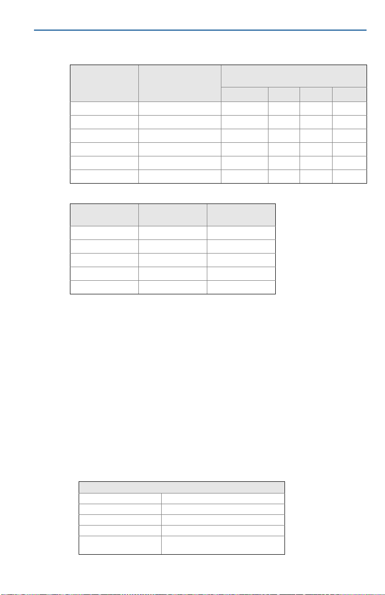
Table 2. Process Temperatures
Process temperature without LCD display
Temperature class Ambient temperature
No ext. 3-in. 6-in. 9-in.
T6 –50 °C to +40 °C 55 55 60 65
T5 –50 °C to +60 °C 70 70 70 75
T4 –50 °C to +60 °C 100 110 120 130
T3 –50 °C to +60 °C 170 190 200 200
T2 –50 °C to +60 °C 280 300 300 300
T1 –50 °C to +60 °C 440 450 450 450
cover (°C)
Table 3. Entity Parameters
Parameters
Voltage Ui 30 V 45 V
Current Ii 130 mA 26 mA
Power Pi 1 W 290 mW
Capacitance Ci 3.6 nF 2.1 nF
Inductance Li 0 mH 0 μH
HART loop
terminals + and –
Sensor terminals
1 to 4
5.12 Additional Certifications (Rosemount 248 Head Mount only)
SBS American Bureau of Shipping (ABS) Type Approval
Certificate: 11-HS771994B-1-PDA
Intended Use: Measurement of temperature for marine and offshore applications.
SBV Bureau Veritas (BV) Type Approval
Certificate: 26325
Requirements: Bureau Veritas Rules for the Classification of Steel Ships
Application: Class notations: AUT-UMS, AUT-CCS, AUT-PORT and AUT-IMS;
Temperature transmitter cannot be installed on diesel engines.
SDN Det Norske Veritas (DNV) Type Approval
Certificate: A-14187
Intended Use: Det Norske Veritas’ Rules for Classification of Ships, High Speed & Light
Craft and Det Norske Veritas’ Offshore Standards.
Application:
Location classes
Tem pe ra tu r e D
Humidity B
Vibration A
EMC A
Enclosure
B/IP66 Al,
C/IP66: SST
19
Page 20

Quick Start Guide
SLL Lloyds Register (LR) Type Approval
SLL Lloyds Register (LR) Type Approval
Certificate: 11/60002
Certificate: 11/60002
Application: Environmental categories ENV1, ENV2, ENV3, and ENV5
Application: Environmental categories ENV1, ENV2, ENV3, and ENV5
April 2019
20
Page 21
April 2019
EU Declaration of Conformity
No: RMD 1049 Rev. N
Page 1 of 3
We,
Rosemount, Inc.
8200 Market Boulevard
Chanhassen, MN 55317-9685
USA
declare under our sole responsibility that the product,
Rosemount™ 248 Temperature Transmitter
manufactured by,
Rosemount, Inc.
8200 Market Boulevard
Chanhassen, MN 55317-9685
USA
to which this declaration relates, is in conformity with the provisions of the European Union
Directives, including the latest amendments, as shown in the attached schedule.
Assumption of conformity is based on the application of the harmonized standards and, when
applicable or required, a European Union notified body certification, as shown in the attached
schedule.
Vice President of Global Quality
Chris LaPoint
1-April-2019
Figure 3. Rosemount 248 Declaration of Conformity
Quick Start Guide
(signature)
(name)
(function)
(date of issue)
21
Page 22

Quick Start Guide
EU Declaration of Conformity
No: RMD 1049 Rev. N
Page 2 of 3
EMC Directive (2014/30/EU)
Harmonized Standards: EN61326-1:2013, EN61326-2-3:2013
ATEX Directive (2014/34/EU)
Baseefa03ATEX0030X – Intrinsic Safety Certificate
Equipment Group II, Category 1 G
Ex ia IIC T5/T6 Ga
Harmonized Standards:
EN 60079-0: 2012+A11: 2013, EN 60079-11: 2012
BAS00ATEX3145 – Type n Certificate
Equipment Group II, Category 3 G
Ex nA IIC T5 Gc
Harmonized Standards:
EN 60079-0: 2012+A11: 2013, EN 60079-15: 2010
Baseefa13ATEX0045X – Type n Certificate; no enclosure option
Equipment Group II, Category 3 G
Ex nA IIC T5/T6 Gc
Harmonized Standards:
EN 60079-0: 2012+A11: 2013, EN 60079-15: 2010
FM12ATEX0065X – Flameproof Certificate
Equipment Group II, Category 2 G
Ex db IIC T6…T1 Gb
Harmonized Standards:
EN60079-0:2012+A11:2013, EN60079-1:2014
FM12ATEX0065X – Dust Certificate
Equipment Group II, Category 2 D
Ex tb IIIC T130°C Db
Harmonized Standards:
EN60079-0:2012+A11:2013, EN60079-31:2014
April 2019
22
Page 23

April 2019
EU Declaration of Conformity
No: RMD 1049 Rev. N
Page 3 of 3
ATEX Notified Bodies
FM Approvals Europe Limited [Notified Body Number: 2809]
One Georges Quay Plaza
Dublin, Ireland. D02 E440
SGS FIMCO OY [Notified Body Number: 0598]
P.O. Box 30 (Särkiniementie 3)
00211 HELSINKI
Finland
ATEX Notified Body for Quality Assurance
SGS FIMCO OY [Notified Body Number: 0598]
P.O. Box 30 (Särkiniementie 3)
00211 HELSINKI
Finland
Quick Start Guide
23
Page 24

Quick Start Guide
ᴹ
China RoHS
㇑᧗⢙䍘䎵䗷ᴰབྷ⎃ᓖ䲀٬Ⲵ䜘Ԧරࡇ㺘
Rosemount 248
List of Rosemount 248 Parts with China RoHS Concentration above MCVs
䜘Ԧ〠
Part Name
ᴹᇣ⢙䍘䍘Hazardous Substances
䫵
Lead
(Pb)
⊎
Mercury
(Hg)
䭹
Cadmium
(Cd)
ޝԧ䬜䬜
Hexavalent
Chromium
(Cr +6)
ཊⓤ㚄㚄㤟
Polybrominated
biphenyls
(PBB)
ཊⓤ㚄㚄㤟䟊
Polybrominated
diphenyl ethers
(PBDE)
⭥ᆀ㓴Ԧ
Electronics
Assembly
X O O O O
O
༣փ㓴Ԧ
Housing
Assembly
O O O X O
O
Րᝏಘ㓴Ԧ
Sensor
Assembly
X O O O O
O
ᵜ㺘Ṭ㌫ᦞ
SJ/T11364
Ⲵ㿴ᇊ㘼ࡦ
This table is proposed in accordance with the provision of SJ/T11364.
O:
Ѫ䈕䜘ԦⲴᡰᴹ൷䍘ᶀᯉѝ䈕ᴹᇣ⢙䍘Ⲵ䟿൷վҾ
GB/T 26572
ᡰ㿴ᇊⲴ䲀䟿㾱≲
O: Indicate that said hazardous substance in all of the homogeneous materials for this part is below the limit requirement of
GB/T 26572.
X:
Ѫ൘䈕䜘Ԧᡰ֯⭘Ⲵᡰᴹ൷䍘ᶀᯉ䟼ˈ㠣ቁᴹа㊫൷䍘ᶀᯉѝ䈕ᴹᇣ⢙䍘Ⲵ䟿儈Ҿ
GB/T 26572
ᡰ㿴ᇊⲴ䲀䟿㾱≲
X: Indicate that said hazardous substance contained in at least one of the homogeneous materials used for this part is above
the limit requirement of GB/T 26572.
April 2019
24
Page 25

April 2019
Quick Start Guide
25
Page 26

Global Headquarters
Emerson Automation Solutions
6021 Innovation Blvd.
Shakopee, MN 55379, USA
+1 800 999 9307 or +1 952 906 8888
+1 952 949 7001
[email protected]
North America Regional Office
Emerson Automation Solutions
8200 Market Blvd.
Chanhassen, MN 55317, USA
+1 800 999 9307 or +1 952 906 8888
+1 952 949 7001
[email protected]
Latin America Regional Office
Emerson Automation Solutions
1300 Concord Terrace, Suite 400
Sunrise, FL 33323, USA
+1 954 846 5030
+1 954 846 5121
[email protected]
Europe Regional Office
Emerson Automation Solutions
Neuhofstrasse 19a P.O. Box 1046
CH 6340 Baar
Switzerland
+41 (0) 41 768 6111
+41 (0) 41 768 6300
[email protected]
Asia Pacific Regional Office
Emerson Automation Solutions
1 Pandan Crescent
Singapore 128461
+65 6777 8211
+65 6777 0947
[email protected]
Middle East and Africa Regional Office
Emerson Automation Solutions
Emerson FZE P.O. Box 17033
Jebel Ali Free Zone - South 2
Dubai, United Arab Emi rates
+971 4 8118100
+971 4 8865465
*00825-0100-4825*
Quick Start Guide
00825-0100-4825, Rev JB
Linkedin.com/company/Emerson-Automation-Solutions
Twitter.com/Rosemount_News
Facebook.com/Rosemount
Youtube.com/us er/RosemountMeasur ement
Google.com/+RosemountMeasurement
Standard Terms and Conditions of Sale can be found on the Te rm s
and Conditions of Sale page.
The Emerson logo is a trademark and service mark of Emerson
Electric Co.
Rosemount and Rosemount logotype are trademarks of Emerson.
HART is a registered trademark of FieldComm Group.
NEMA is a registered trademark and service mark of the National
Electrical Manufacturers Association.
National Electric Code is a registered trademark of National Fire
Protection Association, Inc.
Windows is a trademark of Microsoft Corporation in the United
States and other countries.
MACTek is a registered trademark of MACTek Corporation.
All other marks are the property of their respective owners.
© 2019 Emerson. All rights reser ved.
April 2019
 Loading...